1
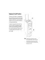
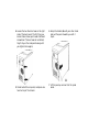
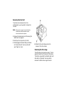
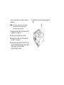
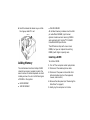
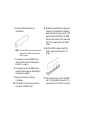
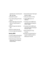
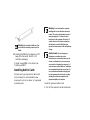
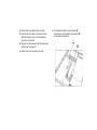
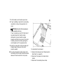
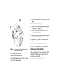
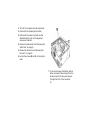
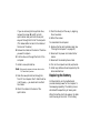
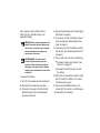
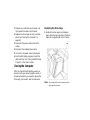
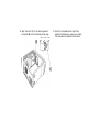
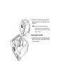
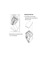
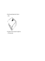
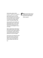
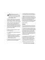
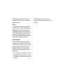
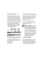
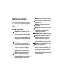
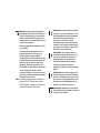
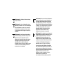
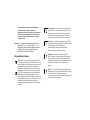
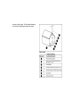
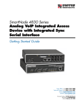
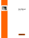
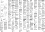
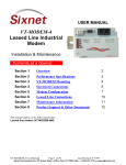
hp pavilion home pc
upgrading and servicing
the pc
The information in this document is subject to change without
notice.
Hewlett-Packard® Company makes no warranty of any kind
with regard to this material, including, but not limited to, the
implied warranties of merchantability and fitness for a
particular purpose.
HP shall not be liable for errors contained herein or for
incidental or consequential damages in connection with the
furnishing, performance, or use of this material.
HP assumes no responsibility for the use or reliability of its
software on equipment that is not furnished by HP.
This document contains proprietary information that is
protected by copyright. All rights are reserved. No part of this
document may be photocopied, reproduced, or translated to
another language without the prior written consent of HP.
Hewlett-Packard Company
Home Products Division
P.O. Box 4010
Cupertino, CA 95015-4010
USA
©Hewlett-Packard Company, 2000. All rights reserved.
Hewlett-Packard is a registered trademark of Hewlett-Packard
Company in the United States of America and other
countries.
Other brand or product names are trademarks of their
respective holders.
Warning: The HP Pavilion PC may come with
software that allows you to copy audio files in
the MP3 format. Unauthorized reproduction
and distribution of audio MP3 files, or any
portion of them, can result in civil and criminal
penalties.
Features of the HP Pavilion
On the top of the chassis is a CD holder (A).
Store the CDs that came with the HP Pavilion
inside this compartment, so you can quickly
locate them if you ever need to reinstall any
of the system applications.
To connect components to the front of the
PC, flip up the port cover (B) and plug the
cables into the corresponding connectors.
For more information about these ports, see
“Connecting External Components” in the
User’s Guide.
Note: The power supply is pre-set for the country in
which you purchased the HP Pavilion. If you move
to another location, please make sure you check
the voltage requirements in the country you reside
before turning on the PC.
station de protection contre les décharges
électrostatiques, portez un bracelet
antistatique relié à une partie métallique de
l'ordinateur. Placez les cartes sur un tapis en
mousse conducteur ou dans leur emballage,
mais ne les posez jamais sur leur emballage.
Opening the Computer
Warning: The HP Pavilion is heavy; be sure
to use ergonomically correct lifting
procedures when moving the computer.
Warning: Do not operate the system with
Avertissement : L’ordinateur HP Pavilion
the cover removed. Always replace the
cover before turning on the system.
est lourd ; suivez des procédures
ergonomiques lorsque vous le déplacez.
Avertissement : N’utilisez pas le système
lorsque son capot est ouvert. Remettez
toujours le capot en place avant de mettre le
système sous tension.
Warning: Electrostatic discharge (ESD) can
damage disk drives, add-in cards, and other
components. If an ESD station is not available,
wear a wrist strap attached to a metal part of
the computer. Place cards on a conductive
foam pad or inside the conductive wrapper
they came in; do not place the cards on top
of the wrapper.
Avertissement : Des décharges
électrostatiques peuvent endommager les
unités de disque, cartes d'extension et autres
composants. Si vous ne disposez pas d'une
Before You Begin
Read the following items before attempting
to upgrade or service the computer:
n
These procedures assume familiarity with
the general terminology associated with
personal computers and with the safety
practices and regulatory compliance
required for using and modifying
electronic equipment.
n
n
n
Set up an equipment log to record the
system model and serial numbers, all
installed options, and other information
about the system. If you need this
information, it will be easier to consult the
log than to open up and examine the
system.
HP recommends that you use an antistatic
wrist strap and a conductive foam pad
when working on the system.
Disconnect the system from any
telecommunications links, networks,
or modems, and then disconnect the
system power source before performing
any of the procedures described in this
guide. Failure to do so before you open the
system or do any procedures can result in
personal injury or equipment damage.
Note: Disconnect the modem/phone cable before
disconnecting the power cord from the system.
To gain access to the inside of the computer,
remove the side panel.
Removing the Side Panel
You must remove the side panel to add
memory, insert add-in cards, install or
remove drives, or change the battery.
1 Turn off the computer and all peripherals.
2 Disconnect the modem/phone cable.
3 Disconnect the power cord and all other
attached cables (such as the keyboard,
mouse, and monitor).
4 Loosen the two thumb screws on the right
side of the back panel. The first time you
loosen these screws you’ll need a flathead
screwdriver. (These screws do not detach;
they’ll stay on the side panel loosely until
you tighten them again.)
5 Stand behind the computer, and place one
hand on top of the chassis.
6 Grasp the handle (A) with your other hand
and pull the panel towards you until it
stops.
7 Lift the panel up and out. Set the panel
aside.
Removing the Fan Duct
To access some components on the
motherboard, you may need to remove the
fan duct.
Note: Make sure the computer is turned off and the
modem/phone cable and power cord are
disconnected from the computer.
1 Remove the side panel (see “Removing the
Side Panel” on page 3).
2 Gently lay the computer on its side.
3 To disengage the fan duct (B), push down
on the two tabs (C). You can push with
your fingers or a pen.
4 Rotate the fan duct down and out to
remove it from the chassis.
Removing the Drive Cage
The HP Pavilion has two drive cages. The top
cage that holds the CD drive(s) is stationary.
The bottom cage holds the diskette and hard
drive and is removable. You may need to
remove this bottom drive cage to access
internal components or to add or replace a
hard drive.
Note: Make sure the computer is turned off and the
modem/phone cable and power cord are
disconnected from the computer.
1 Remove the side panel (see “Removing the
Side Panel” on page 3).
2 Gently lay the computer on its side.
3 Remove the fan duct (see “Removing the
Fan Duct” on page 5).
4 Remove the power and IDE cables from the
back of the diskette and hard drives. Make
note of each connection before
disconnecting the cables.
5 Push down on the drive cage release tab
(D).
6 Hold the release tab down as you rotate
the cage up and lift it out.
n
256 MB SDRAM
All installed memory modules must be 168pin unbuffered SDRAM (synchronous
dynamic random access memory) DIMMs
and compliant with the Intel® PC SDRAM
Unbuffered DIMM Specification.
The HP Pavilion ships with one or more
DIMMs, but you can replace the existing
DIMM(s) with higher capacity ones.
Installing a DIMM
Adding Memory
The motherboard contains 168-pin DIMM
(dual-inline memory module) sockets; the
exact number of sockets depends on which
model you have. You can install these types
of DIMMs in the system:
n
64 MB SDRAM
n
128 MB SDRAM
To install a DIMM:
1 Turn off the computer and all peripherals.
2 Disconnect the modem/phone cable.
3 Disconnect the power cord and all other
attached cables (such as the keyboard,
mouse, and monitor).
4 Remove the side panel (see “Removing the
Side Panel” on page 3).
5 Gently lay the computer on its side.
6 Locate the DIMM sockets on the
motherboard.
Note: If all of the DIMM sockets are filled, you need to
remove one of the DIMMs (see “Removing a
DIMM” on page 9).
11 Holding the new DIMM by its edges only,
remove it from the antistatic packaging.
(Avoid touching the memory chips or the
gold contacts on the DIMM.) The DIMM
has two small notches on the lower edge
that fit into raised bumps in the DIMM
socket.
12 Hold the DIMM in alignment with the
socket, aligning the notches with the
bumps.
7 If necessary to reach the DIMM socket,
remove the fan duct (see “Removing the
Fan Duct” on page 5).
8 If necessary to reach the DIMM socket,
remove the drive cage (see “Removing the
Drive Cage” on page 5).
9 Move any cabling out of the way,
if necessary.
10 Push down on the two retaining clips on
the ends of the DIMM socket.
13 Push straight down on top of the DIMM
until it is fully seated in the socket. The
retaining clips on the ends of the socket
automatically lock it into position when the
DIMM is fully seated.
4 Remove the side panel (see “Removing the
Side Panel” on page 3).
To reassemble the computer:
5 Gently lay the computer on its side.
1 If you moved any cabling, put them back
into place.
6 Locate the DIMM sockets on the
motherboard.
2 Replace the drive cage, fan duct, and side
panel (see “Closing the Computer” on
page 20).
7 If necessary to reach the DIMM socket,
remove the fan duct (see “Removing the
Fan Duct” on page 5).
3 Reconnect the power cord and all other
cables.
8 If necessary to reach the DIMM socket,
remove the drive cage (see “Removing the
Drive Cage” on page 5).
4 Reconnect the modem/phone cable.
5 Turn on the computer and all peripherals.
Removing a DIMM
1 Turn off the computer and all peripherals.
2 Disconnect the modem/phone cable.
3 Disconnect the power cord and all other
attached cables (such as the keyboard,
mouse, and monitor).
9 Move any cabling out of the way,
if necessary.
10 Push down on the two retaining clips on
the ends of the DIMM socket until the
DIMM pops out of the socket.
Warning: Do not overload the system by
Warning: Do not pull the DIMM out of the
socket. Use the retaining clips to eject the
DIMM.
11 Holding the DIMM by its edges only, lift it
away from the socket. Store it in its
antistatic packaging.
To install a new DIMM in this socket, see
“Installing a DIMM.”
Installing Add-In Cards
At some point, you may want to add a card
to the computer to accommodate a new
component, such as a scanner, or to upgrade
an existing card.
installing add-in cards that draw excessive
current. The system is designed to provide 2
amps (average) of +5 V power for each
board/card in the computer. The total +5 V
current draw in a fully loaded system (one
with all add-in card slots filled) must not
exceed the total number of slots multiplied by
2 amps.
Avertissement : Ne surchargez pas
l'ordinateur en installant des cartes
d'extension qui consomment beaucoup de
courant. L'ordinateur est conçu pour fournir
un courant de 2 ampères (en moyenne), +5
volts, à chaque carte installée sur l'ordinateur.
La consommation totale de courant de +5 V
sur un ordinateur entièrement chargé (dont
tous les logements de cartes sont occupés)
ne doit pas excéder le nombre total de
supports multiplié par 2 ampères.
To add or replace an add-in card:
1 Turn off the computer and all peripherals.
2 Disconnect the modem/phone cable.
3 Disconnect the power cord and all other
attached cables (such as the keyboard,
mouse, and monitor).
4 Remove the side panel (see “Removing the
Side Panel” on page 3).
5 Gently lay the computer on its side.
6 To release the add-in card bracket (A),
push down on the release mechanism (B)
as you pull the bracket.
7 Pull the add-in card bracket up and out.
8 If you’re adding a new card to a previously
unused slot, remove the expansion slot
cover.
Warning: Be careful of the sharp edges on
the expansion slot cover.
If you’re replacing a card, first disconnect
any external and/or internal cables
attached to the card. Hold the metal
bracket and the far top corner of the card.
Carefully remove the card by pulling the
card straight out of the expansion slot.
9 Insert the new card into the slot and push
straight down. Make sure the card is
properly seated.
10 To replace the add-in card bracket, slide
the bracket into the hole (C) and then push
down until the bracket clicks into place.
To reassemble the computer:
1 Replace the side panel (see “Replacing the
Side Panel” on page 23).
2 Reconnect the power cord and all other
cables.
3 Reconnect the modem/phone cable.
4 Turn on the computer and all peripherals.
5 Install any software drivers supplied by the
card manufacturer.
What Is Plug and Play?
“Plug and Play” describes the ability to add
and remove add-in cards, memory, and
peripherals without any special procedures
(such as resetting jumpers and testing for
system conflicts). The system BIOS (basic
input/output system) finds these
components and adds them to the system.
You do not have to run the BIOS Setup
program.
program and load the default settings, and
then save and exit. (See “Using the BIOS
Setup Program” in the User’s Guide for more
information.)
Adding and Removing Drives
You can install a second hard drive into the
system or replace the existing hard drive. In
addition, you can replace the existing
diskette or optical drives.
Installing a Second Hard Drive
The HP Pavilion has an empty 3.5-inch drive
bay to accommodate an additional hard
drive.
If the New Card or Device Isn’t
Working
1 Turn off the computer and all peripherals.
Read through the card manufacturer’s
installation instructions, and recheck all
connections, including those to the card,
power supply, keyboard, and monitor. If the
problem still exists, run the BIOS Setup
3 Disconnect the power cord and all other
attached cables (such as the keyboard,
mouse, and monitor).
2 Disconnect the modem/phone cable.
4 Remove the side panel (see “Removing the
Side Panel” on page 3).
5 Remove the drive cage (see “Removing the
Drive Cage” on page 5).
Note: Make sure the jumper on the new drive is in the
CS (Cable Select) position.
6 Slide the new drive into the empty bay in
the drive cage, until the screw holes align.
7 Install the screws on the drive cage.
8 Replace the drive cage (see “Replacing the
Drive Cage” on page 20).
9 Attach the power cable to the back of the
drive.
10 Attach the connector marked “Master” on
the IDE ribbon cable to the back of the
primary hard drive. After this primary
connection is attached, twist the
remaining part of the cable marked
“Slave” on that same IDE ribbon cable and
connect it to the secondary hard drive.
11 Connect the IDE cable to the motherboard.
To reassemble the computer:
1 Replace the side panel (see “Replacing the
Side Panel” on page 23).
2 Reconnect the power cord and all other
cables.
3 Reconnect the modem/phone cable.
4 Turn on the computer and all peripherals.
5 Install any software drivers supplied by the
drive manufacturer.
Removing the Preinstalled Hard
Drive
You need to remove the hard drive from the
chassis if you want to replace it with a
higher-capacity drive or if you want to
safeguard your data when sending the
computer out to be repaired.
To remove the preinstalled hard drive:
1 Turn off the computer and all peripherals.
2 Disconnect the modem/phone cable.
3 Disconnect the power cord and all other
attached cables (such as the keyboard,
mouse, and monitor).
4 Remove the side panel (see “Removing the
Side Panel” on page 3).
5 Remove the drive cage (see “Removing the
Drive Cage” on page 5).
6 Remove the two screws on the side of the
hard drive.
7 Pull the hard drive out, and store the drive
and screws in a safe location.
8 Replace the drive cage and the side panel
(see “Closing the Computer” on page 20).
Replacing the Diskette Drive
If you need to replace the diskette drive, you
can remove the existing drive and install a
new one. To ensure that the drive fits
properly into the HP Pavilion, be sure to
purchase the replacement diskette drive from
HP. Refer to your support path card for the
telephone number of the HP Customer Care
Center.
To remove the existing diskette drive:
1 Turn off the computer and all peripherals.
2 Disconnect the modem/phone cable.
3 Disconnect the power cord and all other
attached cables (such as the keyboard,
mouse, and monitor).
4 Remove the side panel (see “Removing the
Side Panel” on page 3).
5 Remove the drive cage (see “Removing the
Drive Cage” on page 5).
6 Remove the screw (A) on each side of the
diskette drive.
2 Attach the screws on each side of the drive
cage.
To reassemble the computer:
1 Replace the drive cage (see “Replacing the
Drive Cage” on page 20).
2 Reattach the cables to the back of the
hard and diskette drives.
3 Replace the side panel (see “Replacing the
Side Panel” on page 23).
4 Reconnect the power cord and all other
cables.
5 Reconnect the modem/phone cable.
6 Turn on the computer and all peripherals.
Note: The second screw (A) is on the other side of
the drive cage (not pictured).
7 Pull the diskette drive out.
To install a new diskette drive:
1 Slide the diskette drive into the drive cage,
until the screw holes align.
Replacing an Optical Drive
Your computer comes with two optical drives
(CD-ROM, DVD, and/or CD-Writer) that you
can replace or upgrade.
To remove an existing optical drive:
1 Turn off the computer and all peripherals.
2 Disconnect the modem/phone cable.
3 Disconnect the power cord and all other
attached cables (such as the keyboard,
mouse, and monitor).
4 Remove the side panel (see “Removing the
Side Panel” on page 3).
5 Remove the fan duct (see “Removing the
Fan Duct” on page 5).
6 Locate the screws (B and C) on the optical
drive.
7 If you are removing the bottom optical
drive, remove the two screws (C) on the
drive and push the drive part way out
through the front of the computer.
Or
If you are removing the top optical drive,
remove the screws (B and C) on both
optical drives and push both drives part
way out through the front of the computer.
(This allows better access to the cables at
the back of the drive.)
8 Remove the cables on the back of the drive
you want to replace.
3 Push the drive(s) all the way in, aligning
the screw holes.
4 Attach the screws.
To reassemble the computer:
1 Replace the fan duct and side panel (see
“Closing the Computer” on page 20).
2 Reconnect the power cord and all other
cables.
9 Pull the drive out through the front of the
computer.
3 Reconnect the modem/phone cable.
To install a new optical drive:
4 Turn on the computer and all peripherals.
Note: Make sure the jumper on the new drive is in the
5 Install any software drivers supplied by the
drive manufacturer.
CS (Cable Select) position.
1 Slide the new optical drive through the
front of the computer. Don’t slide the drive
in all the way — you need room to attach
the cables.
2 Attach the cables to the back of the
optical drive.
Replacing the Battery
A lithium battery on the motherboard
provides backup power for the computer’s
timekeeping capability. The battery has an
estimated life expectancy of seven years.
When the battery starts to weaken, the date
and time may be incorrect. If the battery
fails, replace it with a CR2032 lithium
battery (3 volt, 220mAH rating) or an
equivalent battery.
Warning: There is danger of explosion if the
battery is incorrectly replaced. Replace only
with the same, or equivalent, type of battery.
Discard used batteries according to the
manufacturer’s instructions.
Avertissement : Le remplacement
incorrect de la pile peut provoquer une
explosion. Utilisez uniquement une pile de
même type ou de type équivalent. Éliminez
les piles usées conformément aux instructions
du fabricant.
To replace the battery:
1 Turn off the computer and all peripherals.
2 Disconnect the modem/phone cable.
3 Disconnect the power cord and all other
attached cables (such as the keyboard,
mouse, and monitor).
4 Remove the side panel (see “Removing the
Side Panel” on page 3).
5 If necessary to reach the battery, remove
the drive cage (see “Removing the Drive
Cage” on page 5).
6 If necessary to reach the battery, remove
the fan duct (see “Removing the Fan Duct”
on page 5).
7 If any cards restrict access to the battery:
n
Remove the add-in card bracket. (See
steps 6–7 on page 11.)
n
Remove the cards that are on or near
the battery.
8 With a pen or screwdriver, press the metal
latch that holds the battery in its socket.
The battery will pop out.
9 Install the new CR2032 battery in the
socket, with the positive (+) side facing up.
To reassemble the computer:
1 Replace any cards that you removed, and
then replace the add-in card bracket.
2 Replace the drive cage, fan duct, and side
panel (see “Closing the Computer” on
page 20).
Replacing the Drive Cage
1 Holding the drive cage at a 45-degree
angle, slide the two nubs (A) on the drive
cage into the guides (B) on the chassis.
3 Reconnect the power cord and all other
cables.
4 Reconnect the modem/phone cable.
5 Turn on the computer and all peripherals.
6 Run the BIOS Setup program to reset the
date and time. (See “Using the BIOS Setup
Program” in the User’s Guide.)
Closing the Computer
After you have finished installing memory or
drives, inserting or replacing add-in cards, or
changing the battery, you need to replace the
drive cage, the fan duct, and the side panel.
Note: The second nub (A) is on the other side of the
drive cage (not pictured).
2 Align the track (C) on the drive cage with
the guide (D) on the stationary drive cage.
3 Push the removable drive cage firmly
against the stationary cage as you rotate
the removable drive down into position.
4 To make sure that the cage is locked into
position, grasp the drive cage and pull up
forcefully.
Note: If you are able to remove the drive cage
without pressing the release tab, you didn’t
properly align the track with the guide. Repeat
steps 1–4 above.
Replacing the Fan Duct
1 Holding the fan duct at a 45-degree angle,
align the bottom of the duct with the hole
on the fan holder.
Replacing the Side Panel
1 Lay the panel on top of the chassis,
aligning the notches on the panel with the
holes on the chassis.
2 Rotate the fan duct into position and make
sure it’s securely locked.
2 Slide the panel forward until it locks in
place.
3 Tighten the thumb screws on the right side
of the back panel.
Regulatory and Safety
Information
Declaration of Conformity
According to ISO/IEC Guide 22 and EN 45014
Manufacturer’s Name:
Hewlett-Packard Company
Manufacturer’s Address:
10500 Ridgeview Ct.
Cupertino, CA 95015-4010
USA
declares that the product
Product
HP Pavilion Multimedia Personal Computer
Name:
System
Model
78XXY (X is any number 0-9, Y is any
Number(s):
alphanumeric character or blank)
XT8ZZ (Z is any number 0-9)
Product
All
Options:
conforms to the following Product Specifications:
Safety:
IEC 60950:1991 + A1, A2, A3, A4
EN 60950:1992 + A1, A2, A3, A4, A11
EMC
CISPR 22:1993 +A1+A2/ EN 55022:1994 +A1+A2:
Class B 1)
EN 50082-1:1992 – Generic Immunity
IEC 801-2:1991/prEN 55024-2:1992 - 4 kV CD, 8 kV AD
IEC 801-3:1984/prEN 55024-3:1991 - 3V/m
IEC 801-4:1988/prEN 55024-4:1992 - 0.5 kV Signal
Lines,
1 kV Power Lines
IEC 61000-3-2:1998/EN61000-3-2:1998 - Harmonics
IEC 61000-3-3:1994/EN61000-3-3:1995 - Flicker
FCC Title 47 CFR, Part 15 Class B 2)/ICES-003, Issue 2
AS/NZS 3548:1995/CISPR 22:1993 +A1+A2 Class B1)
AS/NZS 3548:1995/CISPR 22:1993 +A1+A2 Class B1)
Telecom:
TBR 21:1998, EG201 121:1998
Supplementary Information:
The product herewith complies with the requirements of the
following Directives and carries the CE marking accordingly.
-the EMC Directive 89/336/EEC (including 93/68/EEC)
-the Low Voltage Directive 73/23/EEC (including
93/68/EEC)
-the R&TTE Directive 1999/5/EC
1)
The Product was tested in a typical configuration with
Hewlett-Packard Personal Computer peripherals.
2)
This Device complies with Part 15 of the FCC Rules.
Operation is subject to the following two conditions: (1) this
device may not cause harmful interference, and (2) this
device must accept any interference received, including
interference that may cause undesired operation.
Hardware Quality Engineering Manager
Cupertino, CA, USA November, 2000
For Regulatory Compliance Information ONLY, contact:
Australian
Product Regulations Manager
Contact:
Hewlett-Packard Australia Ltd.
31-41 Joseph Street
Blackburn, Victoria 3130, Australia
European
Hewlett-Packard GmbH. HQ-TRE
Contact:
Herrenberger Straße 110-140
D-71034 Böblingen, Germany
(FAX: + 49-7031-14-3143)
North America
Hardware Quality Engineering Manager,
Contact:
Hewlett-Packard, HPD,
10500 Ridgeview Ct.,
Cupertino, CA 95015-4010,
USA
(Phone: 408-343-5000)
FCC Regulatory and Safety
Information (USA Only)
Hewlett-Packard’s system RFI and Radiated Immunity
tests were conducted with HP-supported peripheral
devices and HP-shielded cables, such as those you
receive with your system. Changes or modifications not
expressly approved by Hewlett-Packard could void the
user’s authority to operate the equipment. To comply with
the limits for an FCC Class B computing device, always
use shielded signal cables and the power cord supplied
with this unit.
Federal Communications Commission (FCC) Radio
Frequency Interference Statement
Warning: This equipment has been tested and found
to comply with the limits for a Class B digital device,
pursuant to Part 15 of the FCC Rules. These limits are
designed to provide reasonable protection against
harmful interference in a residential installation. This
equipment generates, uses, and can radiate radio
frequency energy and, if not installed and used in
accordance with the instructions, may cause harmful
interference to radio communications. However,
there is no guarantee that interference will not occur
in a particular installation. If this equipment does
cause harmful interference to radio or television
reception, which can be determined by turning the
equipment off and on, the user is encouraged to
correct the interference by one or more of the
following measures:
n
Reorient or relocate the receiving antenna.
n
Increase the separation between the equipment and
the receiver.
Connect the equipment into an outlet that is on a
circuit different from the receiver.
Consult the dealer or an experienced radio/TV
technician for help.
n
n
Consumer Information and FCC
Requirements
Telephone Connection
n
n
This equipment complies with Part 68 of the Federal
Communications Commission rules. These rules
permit this device to be directly connected to the
telephone network. Standardized jacks are used for
these connections. This equipment should not be
used on party lines or coin lines.
If this device is malfunctioning, it may also cause
harm to the telephone network; this device should
be disconnected until the source of the problem can
be determined and until it has been repaired. If this
is not done, the telephone company may temporarily
disconnect your service.
n
n
The telephone company may make changes in its
technical operations and procedures. If such
changes affect the compatibility or use of this
device, the telephone company is required to give
adequate notice of the changes.
If the telephone company requests information on
what equipment is connected to their lines, inform
them of:
a The telephone number this unit is connected to
b The ringer equivalence number
c The USOC jack required: RJ-11C
d The FCC Registration Number
Items (b) and (c) are indicated on the label. The
ringer equivalence number (REN) is used to
determine how many devices can be connected to
your telephone line. In most areas, the sum of the
RENs on any one line should not exceed five (5.0). If
too many devices are attached, they may not ring
properly.
n
In the event of equipment malfunction, HewlettPackard or an authorized HP Personal Computer
Dealer Repair Center should perform all repairs. It is
the responsibility of users requiring service to report
the problem to HP’s Home Products Division, or to
one of our authorized agents. Service can be
obtained by calling the HP Customer Care Center at
208-323-4663 (United States).
Statement of Fax Branding
The Consumer Protection Act of 1991 makes it
unlawful for any person to use a computer or other
electronic device to send any message via telephone
fax machine, unless it clearly contains: a margin at the
top or bottom of each transmitted page or on the first
page of the transmission, the date and time it is sent,
identification of the business or other entity, or
individual sending the message, the telephone number
of the sending machine or such business, entity, or
individual.
ENERGY STAR Compliance
Hewlett-Packard Pavilion PCs and monitors marked
with the ENERGY STAR logo comply with the U.S.
Environmental Protection Agency’s ENERGY STAR
guidelines for energy efficiency. For information on
changing power management features, refer
to “Putting the Computer into Standby and Hibernation
Mode” in the Quick Start Guide.
ENERGY STAR is a U.S. registered service mark of the
United States Environmental Protection Agency.
Canada Department of
Communications (DOC) Notice
Telephone Connection
The Canada Department of Communications label
identifies certified equipment. This certification means
that the equipment meets certain telecommunications
network protective, operational, and safety
requirements. The department does not guarantee the
equipment will operate to the user’s satisfaction.
Before installing this equipment, the user should
ensure it is permissible to connect it to the facilities of
the local communications company. The equipment
must be installed using an acceptable method of
connection. In some cases, the company’s inside
wiring associated with a single line individual service
may be extended by means of a certified connector
assembly (telephone extension cord). The customer
should be aware that compliance with the above
conditions may not prevent degradation of service in
some situations.
Repairs to certified equipment should be made by an
authorized Canadian maintenance facility designated
by the supplier. Any repairs or alterations made by the
user to this equipment, or equipment malfunctions,
may give the telecommunications company cause to
request that the user disconnect the equipment.
Users should ensure, for their own protection, that the
electrical ground connections of the power utility,
telephone lines, and internal metallic water pipe
systems, if present, are connected together. This
precaution may be particularly important in rural
areas.
Warning: Users should not attempt to make such
connections themselves, but should contact the
appropriate electrical inspection authority or
electrician, as appropriate.
Avertissement : L’utilisateur ne devrait pas tenter
de faire ces connexions lui-même mais devrait
utiliser les services de l’organisme approprié
d’inspection des installations électriques ou d’un
électricien, selon le cas.
Warning: The Load Number .9 assigned to each
terminal device denotes the percentage of the total
load to be connected to a telephone loop; this is
used by the device to prevent overloading. The
termination on a loop may consist of any
combination of devices, subject only to the
requirement that the sum of the Load Numbers does
not exceed 100.
Avertissement : La valeur de charge .9 attribuée à
chaque élément terminal indique le pourcentage de
la charge totale pouvant être connecté à une
boucle téléphonique. Cette valeur est utilisée pour
éviter les surcharges. La terminaison d’une boucle
peut être constituée d’une combinaison quelconque
d’équipements, dans la mesure où la somme des
valeurs de charge ne dépasse pas 100.
DOC Statement (Canada Only)
This Class B digital apparatus meets all requirements
of the Canadian Interference-Causing Equipment
Regulations.
Cet appareil numerique de la classe B respecte toutes
les exigences du Reglement sur le materiel brouilleur
du Canada.
Austel Statement (Australia Only)
When setting the number of automatic redials for the
modem, ensure the following: The number of
automatic redials that the modem performs should be
limited to a maximum of 9 redials plus the original
call. If the above retries are unsuccessful, no further
attempts should be made to the same number for a
minimum period of five minutes.
Warning: Failure to set the modem, and any
communication software used with the modem, to
the values contained in the listing will result in the
modem being operated in a non-compliant manner.
Consequently, there would be no permit in force for
this equipment, and the Telecommunications Act
1991 prescribes a penalty of A$12,000 for the
connection of non-permitted equipment.
Australia/New Zealand Telecom Statement
Your modem has been granted an Austel Permit for use
in Australia and a New Zealand Telecom Telepermit for
use in New Zealand. In each country, special
conditions apply to the settings and features of your
modem. Failure to observe these conditions might
result in heavy penalties being applied (up to
A$12,000.00 in Australia).
Warning: For safety reasons, only connect
equipment with a telecommunications compliance
label. This includes customer equipment previously
labeled, permitted or certified.
The grant of a Permit/Telepermit in no way indicates
the telecom agency’s acceptance of responsibility for
the correct operation of that device under all operating
conditions. In particular, the higher speeds at which
this modem is capable of operating depend on a
specific network implementation which is only one of
many ways of delivering high-quality voice telephone to
customers. Failure to operate should not be reported
as a fault to Telecom or Austel.
In addition to satisfactory line conditions, a modem
can work properly only if:
It is compatible with the modem at the other end of
the call, and
n The application using the modem is compatible with
the application at the other end of the call; for
example, accessing the Internet requires suitable
software in addition to a modem.
This equipment shall not be used in any manner which
could constitute a nuisance to other customers.
n
The setting and features discussed below influence
how your modem reacts with the telephone network. If
changes from the default values are made, then it is
possible that unwanted signals or interference may be
generated, your modem might dial wrong numbers or
suffer from a reduced level of performance. We
strongly recommend that the settings are not changed
under any circumstances or the Permit/Telepermit
may become invalid.
Initialization
Many communications programs react to the default
settings when started. This is usually achieved by the
ATZ command and initializes your modem for correct
operation. Many programs are developed for worldwide
use and generally use the ATZ command; however,
some programs have built-in modem configuration
utilities and these should not be used unless you can
confirm that they are compatible with Australian and
New Zealand requirements.
If your program does not use the ATZ command to
initialize, but instead sends a complex string of
characters, then it must be configured to send the
correct string for Australia and New Zealand. The
correct initialization string is (spaces should not
be entered; they are to make it easier to read):
AT &F T /N6 S6=3 S7=45 % L=7 &Y0 &W0
Once you have entered this command string, it is
written to the internal memory of the modem and the
default configuration.
Dialing
The modem supports both pulse and tone dialing in
Australia and only tone dialing in New Zealand. New
Zealand users please note that if pulse dialing is
selected, then wrong numbers will be dialed, as the
reverse numbering scheme is not supported. There are
several dial string modifiers referred to in the main
users’ manual, and we suggest that they be used with
caution to avoid problems when making calls.
Automatic Answering
To conform with Austel and Telecom New Zealand
requirements when configuring your modem for autoanswering, please do not set the SO register to values
less than 2 or greater than 10 (Note: ATSO-O will
disable auto-answering). Pre-configured software
should be checked and changed as necessary. These
settings ensure:
n
A person calling your modem will hear a short burst
of ringing before the modem answers. This confirms
that the call has been successfully switched through
the network.
n
Caller identification information (which occurs
between the first and second ring cadences) is not
destroyed.
Automatic Multiple Dialing Attempts
Most communication software can be configured to
make automatic dialing attempts to a telephone
number that is busy or not answering (automatic redial
function). The maximum number of all attempts that
can be made in one sequence must not exceed the
numbers shown in the following table. If your program
makes continuous automatic dialing attempts or more
than the number in the table, and it cannot be
changed, an alternative program must be used or
automatic dialing disabled. There is no limit for
manually initiated dialing attempts.
Country
Number of
Pauses
attempts per between
sequence
attempts
(seconds)
10
Australia
New Zealand 10
3
60
Pauses
between
sequences
(minutes)
30
60
Bell Compatible Operation
Bell compatible mode should not be used. Nearly all
modems use CCITT mode because Bell mode is limited
to a maximum speed of 300 or 1200 BPS, and some
network interference problems may arise due to line
signaling requirements.
Parallel Telephones
If you find that you regularly experience line noise or
other interference when using your modem, we suggest
disconnecting other telephones from the line. Some
telephones may place a load across the telephone line
when not in use, which adversely affects the
performance of your modem.
If disconnecting parallel telephones reduces the
interference, then it may be necessary to have the
telephone(s) repaired or replaced.
Warning: New Zealand users only: Please note that
operation of this modem on the same line as
telephones or other equipment with audible ringing
devices, or automatic ringing detectors, may cause
“bell tinkle” or false tripping of the ringing detector.
If this occurs, do not contact Telecom Faults Service.
Also, please note that the power consumed from the
telephone line by this modem may not provide for
the effective transfer of a call to or from other
equipment connected to the same line.
Connecting to Other Equipment
There are two telephone line sockets in your modem,
marked LINE and PHONE. The telephone line is
connected to the LINE socket, and other equipment,
such as the telephone, is connected to the PHONE
socket. Please note that Austel permitted/NZ
Telepermitted equipment only may be connected to the
PHONE socket.
Miscellaneous
There are many commands referred to in the main
user’s manual. Incorrect use of some of these
commands may render your modem inoperative or
severely degrade its performance. Generally, it is best
not to change any setting unless you are
an experienced user. Should you accidentally alter any
settings, and are unsure how to undo the changes, it is
best to completely re-initialize your modem by giving
the AT&F command (the only time you should use this
command) and then manually enter the initialization
string of point A. This will reset your modem to the
correct settings for Australia and New Zealand.
Voice Features
If your new modem is fitted with voice features, then it
is illegal in Australia and New Zealand to use it with
software that allows recording of telephone
conversations. (It can be used as an answering
machine, mail box center, telemarketing system, and
so forth, but it cannot be used to record a “live”
conversation between telephone users.) If your
software supports telephone conversation recording
(perhaps called Two-way Recording), then this feature
must be disabled in the program configuration.
EMI Statement (European Union Only)
This is a class B product. In a domestic environment,
this product may cause radio interference in which
case the user may be required to take adequate
measures.
European Telephone Network
Declaration (European Union Only)
The product herewith complies with the requirements
of the R&TTE Directive 1999/5/EC (Annex II) and
carries the CE marking accordingly. However, due to
differences between the individual PSTNs provided in
different countries, the approval does not, of itself, give
an unconditional assurance of successful operation on
every PSTN network termination point. In the event of
problems, you should contact your equipment supplier
in the first instance.
European Network Compatibility
Declarations (European Union Only)
This equipment has been designed to work with
analogue DTMF Networks (TBR-21 compliant).
This equipment may have internetworking difficulties in
PSTN networks that only support Pulse Dialing. Please
consult with your network operator for further
assistance.
UK Compliance Information
This modem is approved by the Secretary of State at
the Department of Trade and Industry for connection
to a single exchange line of the public switch telephone
network run by certain licensed public
telecommunication operators or systems connected
thereto. (Direct exchange lines only, not shared service
or 1-1 carrier systems.)
This modem is also suitable for connection to Private
Automatic Branch Exchanges (PABXs) which return
secondary proceed indication.
If this modem is to be used with a PBX which returns
secondary proceed indication, no more than two
pauses of four seconds duration each should be
inserted between the initial PSTN access digit and the
number to be dialed. This is to avoid interference to
the PTO network.
If this modem is to be used with a PBX which has
extension wiring owned by BT, connection of the
modem to the PBX can only be carried out by BT; or,
by the authorized maintainer of the PNX unless the
authorised maintainer has been given 14 days written
notice that the connection is to be made by another
person, and that period of notice has expired.
This modem is suitable for use only on telephone lines
provided with Loop-Disconnect or Multi-Frequency
Dialling facilities.
Users of this modem are advised that the approval is
for connection to the PSTN via the telephone line
interference supplied with it. Connection of a modem
to the PSTN by any other means will invalidate the
approval.
There is no guarantee of correct working in all
circumstances. Any difficulties should be referred to
your supplier.
Some network operators require that intended users of
their network request permission to connect and for
the installation of an appropriate socket.
Ringer Equivalence Number
The ringer equivalence number (REN) of this modem is
1. REN is a guide to the maximum number of
apparatuses that can be simultaneously connected to
one telephone line. The REN value of each apparatus is
added together, and should not exceed 4. Unless
otherwise marked, a telephone can be assumed to
have a REN value of 1.
Approved Usage
This modem is approved only for the following:
n
n
n
Storage of telephone numbers for retrieval by a
predetermined code
Detection of initial proceed indication
Automatic calling/Automatic answering
n
Tone detection
Operation in the absence as a secondary proceed
indication
n Loudspeaking facility
This modem is NOT suitable for use as an extension to
a payphone.
n
This modem is not approved for connection to UK
private speechband services.
This modem does not support the automatic redial
function.
Any other usage will invalidate the approval of your
modem, if, as a result, it then ceases to conform to the
standards against which approval was granted.
The approval of this modem is INVALIDATED if the
apparatus is subject to modification in any material
way not authorised by the BABT or if it is used with or
connected to external software that has not been
formally accepted by BABT.
Storage of Numbers
It is advisable to check the telephone numbers stored
in your modem immediately after programming.
In order to prevent the misdirection of class and
network interference, please ensure that all manually
programmed telephone numbers are correctly entered.
The number you enter to dial may optionally contain a
PAUSE character (a comma) to allow this modem to
operate with a PABX. Each comma gives a two-second
delay.
Additional Safety Information
This product has not been evaluated for connection to
an “IT” power system (an AC distribution system with
no direct connection to earth, according to IEC
60950).
AC Power Safety Warning
Warning: Install the computer near an AC outlet.
The AC power cord is your HP Pavilion PC’s main AC
disconnecting device and must be easily accessible
at all times. For your safety, the power cord provided
with your system has a grounded plug. Always use
the power cord with a properly grounded wall outlet,
to avoid the risk of electrical shock.
Warning: Your system is provided with a voltage
select switch for use in a 115 or 230 Vac power
system. The voltage select switch has been pre-set to
the correct voltage setting for use in the particular
country where it was initially sold. Changing the
voltage select switch to the incorrect position can
damage your PC and void any implied warranty.
Warning: To reduce the possibility of an electric
shock from the telephone network, plug your
computer into the AC outlet before connecting it to
the telephone line. Also, disconnect the telephone
line before unplugging your computer from the
AC power outlet.
Warning: Always disconnect the modem cord from
the telephone system before installing or removing
your computer cover.
Warning: Do not operate the computer with the
cover removed.
Warning: The power supply is not user-serviceable.
To prevent damage to the power supply, have a
qualified person repair or replace it. All other
components are user-serviceable.
Warning: Electrostatic discharge (ESD) can damage
disk drives, add-in cards, and other components. If
an ESD station is not available, wear a wrist strap
attached to a metal part of the computer. Place
cards on a conductive foam pad or inside the card
wrapper, if possible, but never on the card wrapper.
Warning: For your safety, always unplug the system
from its power source and from any
telecommunications systems (such as phone lines),
networks, or modems before performing any of the
procedures described in this guide. Failure to do so
may result in personal injury or equipment damage.
Hazardous voltage levels are inside the power supply
and modem of this product.
Warning: This modem is designed and approved
independently of the host PC in which it will be used.
The power required by the host PC and all the other
adapter cards installed within it, together with any
auxiliary apparatus, shall not exceed the total power
supply of the host apparatus.
The power requirements of this adapter are +5V (1A)
and -5V (100Ma).
It is essential that when other optional cards are
introduced into the host PC, which may use or
generate a hazardous voltage, a minimum
creepage distance of 5mm and a clearance of 4mm
is maintained between any hazardous voltage and
this modem card. The maximum voltage used or
generated by the host PC is assumed to be up to
250V maximum. If greater voltages are present in the
host, the creepages and clearances must be
increased accordingly. If you have any doubt, seek
advice from a competent engineer before installing
other adapters into the host PC.
Note: A hazardous voltage is one which exceeds 42.4V
peak AC or 60V DC. Clearance is the shortest
distance through air. Creepage is the shortest path
measured along the surface of insulation.
Avertissement : Installez l'ordinateur à proximité
d'une prise c.a. Le cordon d'alimentation c.a. est le
principal dispositif de déconnexion de l'ordinateur
HP Pavilion et doit toujours être facilement
accessible. Pour votre sécurité, le cordon
d'alimentation fourni avec votre système possède
une prise avec mise à la terre. Branchez toujours le
cordon dans une prise murale avec mise à la terre,
afin d'éviter les risques d'électrocution.
Avertissement : Votre système est doté d’un
commutateur de sélection de tension (115 ou 230
volts c.a.). Ce commutateur a été placé sur la
tension appropriée pour le pays dans lequel
l’équipement est initialement vendu. Mettre le
commutateur à la mauvaise position peut
endommager l’ordinateur et annuler toute garantie
implicite.
Avertissement : Pour réduire les risques de choc
électrique en provenance du réseau téléphonique,
branchez votre ordinateur dans une prise c.a. avant
de le connecter à une ligne téléphonique. En outre,
déconnectez votre ligne téléphonique avant de
débrancher votre ordinateur de la prise c.a.
Avertissement : Débranchez la carte modem du
réseau téléphonique avant d'installer ou d'enlever le
couvercle de votre ordinateur.
Avertissement : N’utilisez pas l’ordinateur lorsque
le capot est enlevé.
Avertissement : Le bloc d’alimentation n’est pas
réparable par l’utilisateur. Pour éviter d’endommager
le bloc d’alimentation, confiez-le à un technicien
pour réparation ou remplacement. Tous les autres
composants peuvent être changés ou réparés par
l’utilisateur.
Avertissement : Des décharges électrostatiques
peuvent endommager les unités de disque, cartes
d’extension et autres composants. Si vous ne
disposez pas d’une station de protection contre les
décharges électrostatiques, portez un bracelet
antistatique relié à une partie métallique de
l’ordinateur. Placez les cartes sur un tapis en mousse
conducteur ou dans leur emballage, mais ne les
posez jamais sur leur emballage.
Avertissement : Pour plus de sécurité, débranchez
toujours le système de sa source d’alimentation, de
tout système de télécommunications (comme les
lignes téléphoniques), des réseaux et des modems
avant d’exécuter l’une des procédures décrites dans
ce chapitre. Si vous ne respectez pas ces consignes,
vous risquez de vous blesser et de causer des
dommages matériels. Des niveaux de tension
dangereux se trouvent à l’intérieur du bloc
d’alimentation et du modem de ce produit.
Avertissement : Ce modem est conçu et approuvé
indépendamment de l'ordinateur hôte avec lequel il
est utilisé. L'alimentation électrique nécessaire à
l'ordinateur hôte, à toutes les cartes qui y sont
installées et à tous les appareils auxiliaires ne doit
pas dépasser la puissance totale de l'appareil hôte.
Les exigences d'alimentation électrique de cet
adaptateur sont de +5 V (1 A) et -5 V (100 Ma).
Lorsque d'autres cartes facultatives sont installées
dans l'ordinateur hôte (lesquelles peuvent utiliser ou
produire des tensions dangereuses), il est essentiel
de prévoir une ligne de fuite minimale de 5 mm et un
dégagement de 4 mm entre toute tension
dangereuse et cette carte modem. La tension
maximale utilisée ou produite par le
micro-ordinateur hôte est normalement de 250 V.
Si des tensions plus élevées sont présentes dans
l'ordinateur hôte, les lignes de fuite et les
dégagements doivent être ajustés en conséquence.
En cas de doute, demandez l'avis d'un technicien
compétent avant d'installer d'autres cartes dans
l'ordinateur hôte.
Remarque : Les tensions dangereuses sont celles qui
dépassent 42,4 V c.a. en crête ou 60 V c.c. Le
dégagement est la plus petite distance aérienne.
La ligne de fuite est la plus petite trajectoire
mesurée sur la surface de l'isolation.
Avertissement : L’ordinateur utilise une pile au lithium
de type CR2032. Le remplacement incorrect de la pile
peut provoquer une explosion. Utilisez uniquement une
pile de même type ou de type équivalent. Éliminez les
piles usées conformément aux instructions du fabricant.
Varning! PC:n använder ett litiumbatteri, typ CR2032.
Vid felaktigt batteribyte föreligger risk för explosion. Ersätt
bara med samma eller liknande batterityp,
rekommenderad av tillverkaren. Gör dig av med
batterierna enligt tillverkarens instruktioner.
Advarsel: PCen bruker et litiumbatteri av typen
Lithium Battery Caution
Warning: The PC uses a lithium battery, type CR2032.
There is danger of an explosion if the battery is incorrectly
replaced. Replace only with the same, or equivalent, type
recommended by the manufacturer. Dispose of used
batteries according to the manufacturer’s instructions.
Warnung: In diesem PC wird eine Lithiumbatterie des
Typs CR2032 verwendet. Wenn Sie beim Austauschen
dieser Batterie nicht sachgemäß vorgehen, besteht
Explosionsgefahr. Ersetzen Sie die Batterie nur durch eine
Batterie desselben Typs oder eines entsprechenden, vom
Hersteller empfohlenen Typs. Befolgen Sie bei der
Entsorgung gebrauchter Batterien die Anweisungen des
Herstellers.
CR2032. Dersom det brukes feil batteri, kan det oppstå
fare for eksplosjon. Du må bare bruke batteritypen som
anbefales av produsenten, eller tilsvarende batterier. Følg
produsentens instruksjoner for kassering av brukte
batterier.
Varoitus: PC käyttää CR2032-tyyppistä litiumparistoa.
Räjähdyksen vaara, jos paristo vaihdetaan väärin. Vaihda
vain samanlaiseen tai vastaavaan valmistajan
suosittelemaan paristoon. Käytetyt paristot täytyy hävittää
valmistajan ohjeiden mukaisesti.
Waarschuwing: De PC gebruikt een lithiumbatterij,
type CR2032. Er bestaat explosiegevaar als de batterij
niet goed wordt vervangen. Vervang de batterij uitsluitend
door een batterij van hetzelfde of een gelijkwaardig type,
dat wordt aanbevolen door de leverancier. Behandel
gebruikte batterijen volgens de aanwijzingen van de
leverancier.
Laser Safety Statement
Class 1 LED Product
The CD-ROM and DVD drives contain a laser system
and are classified as a “Class 1 Laser Product” under a
U.S. Department of Health and Human Services
(DHHS) Radiation Performance standard according to
the Radiation Control for Health and Safety Act of
1968.
Should the unit ever require maintenance, contact an
authorized service location.
Warning: Use of controls, adjustments, or
performance procedures other than those specified
in the HP Pavilion PC User’s Guide may result in
hazardous radiation exposure. To prevent direct
exposure to laser beam, do not try to open the
enclosure of the CD-ROM or DVD.
Avertissement : L’utilisation de commandes,
réglages ou procédures de performance autres que
ceux spécifiés dans le Guide de l’utilisateur de
l’ordinateur HP Pavilion peut entraîner une
exposition à des radiations. Afin d’éviter une
exposition directe au rayon laser, ne tentez pas
d’ouvrir le boîtier du lecteur de CD-ROM ou DVD.
TV Antenna Connectors Protection
External Television Antenna Grounding
If an outside antenna or cable system is connected to
the product, be sure the antenna or cable system is
electrically grounded so as to provide some protection
against voltage surges and built-up static charges.
Article 810 of the National Electrical Code, ANSI/NFPA
70, provides information with regard to proper
electrical grounding of the mast and supporting
structure, grounding of the lead-in wire to an antennadischarge unit, size of grounding conductors, location
of antenna-discharge unit, connection to grounding
electrodes, and requirements for the grounding
electrode.
Lightning Protection
For added protection of any Hewlett-Packard product
during a lightning storm, or when it is left unattended
and unused for long periods of time, unplug the
product from the wall outlet and disconnect the
antenna or cable system. This will prevent damage to
the product from lightning and power line surges.
Power Lines
Operating Specifications
An outside antenna system should not be located in
the vicinity of overhead power lines or other electric
light or power circuits, or where it can fall into such
power lines or circuits.
Electrical ratings
Models 78XXY/ XT8ZZ —
100–127 V /200–240 V ,
4/2 A, 50/60 Hz
Operating
temperature
5° to 35° C
Storage
temperature
–40° to 70° C
Warning: When installing an outside antenna
system, extreme care should be taken to keep
from touching such power lines or circuits as
contact with them could be fatal.
Avertissement : Lorsque vous installez une
antenne extérieure, vous devez faire attention
à ne pas toucher ces lignes et circuits
d’alimentation, tout contact pouvant être
mortel.
Operating humidity 15 to 80% @ 26° C
Storage humidity
90% @ 65° C (non-condensing)
Operating altitude
0–2286 m
Storage altitude
0–4572 m