1
Protocol API
CANopen Slave
V3.6.x.x
Hilscher Gesellschaft für Systemautomation mbH
www.hilscher.com
DOC111001API05EN | Revision 5 | English | 2013-10 | Released | Public
Table of Contents
2/191
Table of Contents
1
Introduction.............................................................................................................................................4
1.1 Abstract ..........................................................................................................................................4
1.2 List of Revisions .............................................................................................................................4
1.3 System Requirements....................................................................................................................5
1.4 Intended Audience .........................................................................................................................5
1.5 Specifications .................................................................................................................................6
1.5.1 Technical Data .................................................................................................................................. 6
1.6
1.7
1.8
Terms, Abbreviations and Definitions ..........................................................................................10
References to Documents............................................................................................................10
Legal Notes ..................................................................................................................................11
1.8.1
1.8.2
1.8.3
1.8.4
1.8.5
2
Copyright ......................................................................................................................................... 11
Important Notes............................................................................................................................... 11
Exclusion of Liability ........................................................................................................................ 12
Export .............................................................................................................................................. 12
Registered Trademarks ................................................................................................................... 12
Fundamentals .......................................................................................................................................13
2.1 General Access Mechanisms on netX Systems ..........................................................................13
2.2 Accessing the Protocol Stack by Programming the AP Task’s Queue........................................13
2.2.1 Getting the Receiver Task Handle of the Process Queue ............................................................... 14
2.2.2 Meaning of Source- and Destination-related Parameters................................................................ 14
2.3
Accessing the Protocol Stack via the Dual Port Memory Interface..............................................15
2.3.1 Communication via Mailboxes......................................................................................................... 15
2.3.2 Using Source and Destination Variables correctly........................................................................... 16
2.3.3 Obtaining useful Information about the Communication Channel.................................................... 20
2.4
Client/Server Mechanism .............................................................................................................22
2.4.1 Application as Client ........................................................................................................................ 22
2.4.2 Application as Server ...................................................................................................................... 23
3
Dual-Port-Memory ................................................................................................................................24
3.1 Cyclic Data (Input/Output Data) ...................................................................................................24
3.1.1 Input Data Image............................................................................................................................. 24
3.1.2 Process Data Output ....................................................................................................................... 26
3.2
Acyclic Data (Mailboxes)..............................................................................................................27
3.2.1
3.2.2
3.2.3
3.2.4
3.2.5
3.2.6
3.3
General Structure of Messages or Packets for Non-Cyclic Data Exchange .................................... 28
Status & Error Codes ...................................................................................................................... 30
Differences between System and Channel Mailboxes .................................................................... 30
Send Mailbox................................................................................................................................... 30
Receive Mailbox .............................................................................................................................. 30
Channel Mailboxes (Details of Send and Receive Mailboxes) ........................................................ 31
Status ...........................................................................................................................................32
3.3.1 Common Status............................................................................................................................... 32
3.3.2 Extended Status .............................................................................................................................. 37
3.4
4
Control Block................................................................................................................................41
Getting Started......................................................................................................................................42
4.1 Overview about Essential Functionality .......................................................................................42
4.2 Configuration Parameters and Procedures..................................................................................42
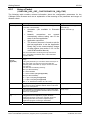
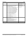
4.2.1 Using a Packet (CANOPEN_APS_SET_CONFIGURATION_REQ/CNF)............................................ 43
4.2.2 Behavior when receiving a Set Configuration Command ................................................................ 45
4.3
4.4
Task Structure of the CANopen Slave V3 Stack..........................................................................45
CANopen – Basic Topics .............................................................................................................47
4.4.1
4.4.2
4.4.3
4.4.4
4.4.5
4.5
NMT Slave State Machine............................................................................................................... 47
Communication Objects, COB-IDs and Priority of Processing ........................................................ 50
Relation between Communication Objects and NMT States ........................................................... 52
Events ............................................................................................................................................. 52
Process Data Objects (PDO)........................................................................................................... 61
Standard Mode vs. Extended Mode.............................................................................................68
4.5.1
4.5.2
4.5.3
4.5.4
4.5.5
How to decide between Operation in Standard Mode and Extended Mode .................................... 68
Where can I switch between Standard Mode and Extended Mode? ............................................... 68
Standard Mode................................................................................................................................ 69
Extended Mode ............................................................................................................................... 71
Object Dictionary with Firmware Functionality................................................................................. 72
CANopen Slave | Protocol API
DOC111001API05EN | Revision 5 | English | 2013-10 | Released | Public
© Hilscher, 2011-2013
Table of Contents
5
3/191
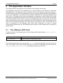
The Application Interface ....................................................................................................................74
5.1 The CANopen-APS-Task .............................................................................................................74
5.1.1 CANOPEN_APS_GET_STATE_REQ/CNF – Get State of AP-Task .................................................... 75
5.1.2 CANOPEN_APS_SET_CONFIGURATION_REQ/CNF – Set Configuration ......................................... 77
5.2
The CANopen Slave-Task ...........................................................................................................85
5.2.1
5.2.2
5.2.3
5.2.4
5.2.5
5.2.6
5.2.7
5.2.8
5.2.9
5.2.10
5.2.11
5.2.12
5.2.13
5.2.14
5.2.15
5.2.16
5.2.17
5.2.18
5.2.19
5.2.20
5.2.21
5.2.22
5.2.23
5.2.24
5.3
CANOPEN_SLAVE_REGISTER_REQ/CNF – Register Application .................................................... 87
CANOPEN_SLAVE_STARTSTOP_REQ/CNF – Start/Stop CANopen Network ................................... 90
CANOPEN_SLAVE_INITIALIZE_REQ/CNF – Initialization of CANopen Slave............................... 93
CANOPEN_SLAVE_EXCHANGE_DATA_REQ/CNF – Exchange Data................................................. 96
CANOPEN_SLAVE_STATE_CHANGE_IND/RES – Change of Task State Indication....................... 100
CANOPEN_SLAVE_SEND_EMCY_REQ/CNF – Send Emergency Message ..................................... 106
CANOPEN_SLAVE_SEND_EMCY_IND/RES – Emergency Message Indication .............................. 110
CANOPEN_SLAVE_SET_NMT_STATE_REQ/CNF – Set NMT State................................................ 114
CANOPEN_SLAVE_SET_BUSPARAM_REQ/CNF – Set Bus Parameters ......................................... 117
CANOPEN_SLAVE_SEND_TIME_STAMP_REQ/CNF – Send Time Stamp ...................................... 122
CANOPEN_SLAVE_RECV_TIME_STAMP_IND/RES – Receive Time Stamp Indication................. 125
CANOPEN_SLAVE_SEND_TXPDO_REQ – Send TxPDO Request ................................................... 128
CANOPEN_SLAVE_RECV_RXPDO_REQ/CNF – Receive RxPDO Request ..................................... 131
CANOPEN_SLAVE_RECV_RXPDO_IND/RES – Receive RxPDO Indication ................................... 135
CANOPEN_SLAVE_SET_EVENTS_INDICATED_REQ/CNF – Set Events Indicated Request ......... 138
CANOPEN_SLAVE_GET_IO_INFO_REQ/CNF – Get I/O Info ......................................................... 142
CANOPEN_SLAVE_SET_API_PARAM_REQ/CNF – Set API Parameter.......................................... 144
CANOPEN_SLAVE_NMT_STATE_CHANGE_IND/RES – NMT State Change Indication .................. 147
CANOPEN_SLAVE_ERR_CTRL_EVENT_IND/RES – Error Control Event Indication ...................... 150
CANOPEN_SLAVE_NMT_COMMAND_IND/RES – NMT Command Indication .................................. 154
CANOPEN_SLAVE_GET_BUSPARAM_REQ/CNF – Get Bus Parameters ......................................... 158
CANOPEN_SLAVE_SET_WATCHDOG_FAIL_REQ/CNF – Set Watchdog Fail.................................. 162
CANOPEN_SLAVE_SETUP_PDO_INDICATION_REQ/CNF – Setup PDO Indication ...................... 164
CANOPEN_SLAVE_RECEIVE_PDO_IND/RES – Receive PDO Indication...................................... 167
Hardware Switches for the Adjustment of Slave Address and Baudrate...................................170
5.3.1 RCX_SET_HW_SWITCH_VALUES_REQ/CNF – Set the Values of the Hardware Switch................. 172
5.3.2 RCX_SET_FW_PARAMETER_REQ/CNF – Set the Value of the Firmware Parameter ..................... 175
5.3.3 RCX_GET_FW_PARAMETER_REQ/CNF – Get the Value of the Firmware Parameter ..................... 179
5.4
5.5
6
CAN-DL Task .............................................................................................................................181
ODV3 Task.................................................................................................................................181
Status/Error Codes Overview............................................................................................................183
6.1.1 Codes of the CANopen-APS-Task ................................................................................................ 183
6.1.2 Error Messages ............................................................................................................................. 183
6.2
Codes of the CANopen Slave-Task ...........................................................................................185
6.2.1 Error Messages ............................................................................................................................. 185
6.3
6.4
7
Codes of CAN-DL Task..............................................................................................................187
Codes of ODV3 ..........................................................................................................................187
Appendix .............................................................................................................................................188
7.1 List of Tables..............................................................................................................................188
7.2 List of Figures.............................................................................................................................190
7.3 Contacts .....................................................................................................................................191
CANopen Slave | Protocol API
DOC111001API05EN | Revision 5 | English | 2013-10 | Released | Public
© Hilscher, 2011-2013
Introduction
1
1.1
4/191
Introduction
Abstract
This manual describes the application interface of the CANopen Slave stack, with the aim to
support and lead you during the integration process of the given stack into your own application.
Base of the development of the stack itself is the Hilscher’s Task Layer Reference Programming
Model. It is a description of how to program a Task in general, which is defined as a combination of
appropriate functions belonging to the same type of protocol layer. It furthermore defines of how
different Tasks have to communicate with each other in order to exchange their layer information in
between. The reference model is commonly used by all programmers at Hilscher and shall be used
by you as well when writing your Application Task on top of the stack.
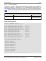
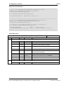
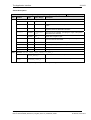
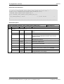
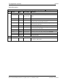
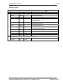
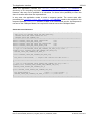
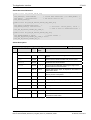
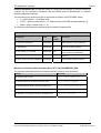
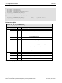
1.2
List of Revisions
Rev
Date
Name
Revisions
1
2012-03-09
RG/ES
Firmware/stack version V3.1.2.x
Reference to netX Dual-Port Memory Interface Manual Revision 12.
Reference to Object Dictionary V3.2.8.0
First final version
2
2012-07-04
RG/ES
Firmware/stack version V3.2.x.x
Added description of packet RCX_SET_FW_PARAMETER_REQ/CNF – Set the
Value of the Firmware Parameter
3
2013-04-11
RG/ES
Firmware/stack version V3.4.3.x
Reference to Object Dictionary V3.3.1.x
Reference to CAN_DL V2.0.22.0
Added description of packet RCX_GET_FW_PARAMETER_REQ/CNF – Get the
Value of the Firmware Parameter
Added description of packet CANOPEN_SLAVE_SEND_EMCY_IND/RES –
Emergency Message Indication
Adapted description of packet
CANOPEN_SLAVE_SET_EVENTS_INDICATED_REQ/CNF – Set Events Indicated
Request to new Send EMCY Event
Adapted Table 51: Packets of CANopen Slave Protocol Stack V3 and Restrictions
of Usage for new Send EMCY Event
4
2013-05-22
RG/ES
Firmware/stack version V3.5.1.x
Reference to Object Dictionary V3.3.1.x
Reference to CAN_DL V2.0.23.0
netX52 now supported
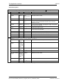
5
2013-10-29
RG/ES
Firmware/stack version V3.6.2.x
Reference to Object Dictionary V3.3.2.x
Reference to CAN_DL V2.0.27.0
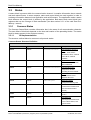
Technical data updated (number of consumers for netX51/52)
Small corrections
Table 1: List of Revisions
CANopen Slave | Protocol API
DOC111001API05EN | Revision 5 | English | 2013-10 | Released | Public
© Hilscher, 2011-2013
Introduction
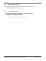
1.3
5/191
System Requirements
The software package has the following system requirements to its environment:
netX-Chip as CPU hardware platform
Operating system for task scheduling required
1.4
Intended Audience
This manual is suitable for software developers with the following background:
Knowledge of the programming language C
Knowledge of the use of the real-time operating system rcX
Knowledge of the Hilscher Task Layer Reference Model
Knowledge of the CiA Work Draft 301 specification
CANopen Slave | Protocol API
DOC111001API05EN | Revision 5 | English | 2013-10 | Released | Public
© Hilscher, 2011-2013
Introduction
1.5
6/191
Specifications
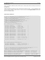
The data below applies to CANopen Slave firmware and stack version 3.6.x. The firmware/stack
has been designed in order to meet the CiA Work Draft 301 V4.02 specification (see reference [2]).
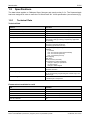
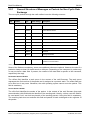
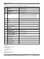
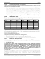
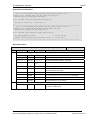
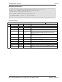
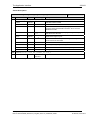
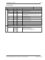
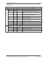
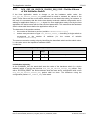
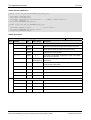
1.5.1
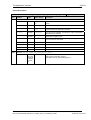
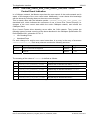
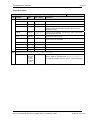
Technical Data
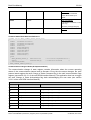
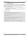
Technical Data
Features
Parameter
Maximum number of input data
Depends on the used mode and settings. See below.
Maximum number of output data
Depends on the used mode and settings. See below.
Maximum number of receive PDOs
Depends on the used mode and settings. See below.
Maximum number of transmit PDOs
Depends on the used mode and settings. See below.
Exchange of process data
via PDO transfer (synchronized, remotely requested,
event driven (change of date)), requested by application
(via packet))
Acyclic communication
SDO Up- and Download (Server only),
Emergency message (producer),
Timestamp (producer/consumer)
Functions
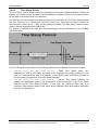
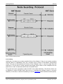
Node guarding / life guarding,
heartbeat
1 producer
max. 64 consumer (netX 50/51/100/500)
max. 32 consumer (netX 52)
max. 4 consumer (netX 10)
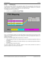
PDO Mapping
NMT Slave
SYNC protocol (consumer)
Error behavior in state operational:
change to state pre-operational
no state change
change to state stopped
Baud rates
10 kBit/s to 1 MBit/s
Automatic detection
Data transport layer
CAN Frames
can be accessed by programming the CAN DL layer, see
reference [5]
CAN Frame type
11 Bit
11/29 Bit layer 2 transparent
Table 2: Technical Data - Protocol Stack
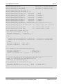
Firmware/stack available for netX
netX
Available
netX 10
yes
netX 50
yes
netX 51
yes (since stack V3.3.1)
netX 52
yes (since stack V3.5.1)
netX 100, netX 500
yes
Table 3: Technical Data – Available for netX
CANopen Slave | Protocol API
DOC111001API05EN | Revision 5 | English | 2013-10 | Released | Public
© Hilscher, 2011-2013
Introduction
7/191
PCI - DMA
Features
Parameter
DMA Support for PCI targets
yes
Table 4: Technical Data – PCI-DMA
Slot Number
Features
Devices
Slot number supported for
CIFX 50-CO, CIFX 50E-CO, CIFX 70E-CO
Table 5: Technical Data – Slot Number
Configuration
For configuration of standard mode with default settings:
by SYCON.net configuration software (Download or exported configuration file named
config.nxd),
by netX Configuration tool.
For configuration of standard mode with default settings and configured settings and extended
mode:
by packet to transfer configuration parameters.
Diagnostic
Firmware supports common and extended diagnostic in the dual-port-memory for loadable
firmware
CANopen Slave | Protocol API
DOC111001API05EN | Revision 5 | English | 2013-10 | Released | Public
© Hilscher, 2011-2013
Introduction
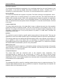
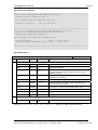
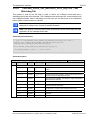
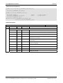
1.5.1.1
8/191
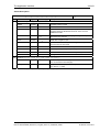
Technical Data (Standard Mode)
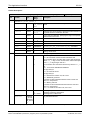
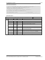
In standard mode, the following values and limitations apply:
Technical Data for default Settings
Features
Parameter
Default number of input data
512 bytes (netX 50/100/500)
64 bytes (netX 10)
Default number of output data
512 bytes (netX 50/100/500)
64 bytes (netX 10)
Default number of receive PDOs
64 (netX 50/100/500)
8 (netX 10)
Default number of transmit PDOs
64 (netX 50/100/500)
8 (netX 10)
Table 6: Technical Data - Protocol Stack (Standard Mode – Default Settings)
Note: The EDS files for Hilscher standard products contain the functionality that matches
the default settings. SYCON.net and the netX Configuration tool only configure the default
settings.
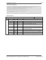
Technical Data for configured Settings
Features
Parameter
Maximum number of input data
1020 bytes
Maximum number of output data
1020 bytes
Number of receive PDOs
0 … 255 (netX 50/100/500)
for mapping objects 2200 … 2203
0 … 8 (netX 10)
for mapping objects 2200 … 2203
Number of transmit PDOs
0 … 255 (netX 50/100/500)
for mapping objects 2000 … 2003
0 … 8 (netX 10)
for mapping objects 2000 … 2003
Table 7: Technical Data - Protocol Stack (Standard Mode – Configured Settings)
Note 1: Using other settings than the default settings requires a suitable EDS file.
Note 2: The actual maximum number of IO Data and PDOs depends on the available
amount of memory.
Note 3: SYCON.net and netX configuration tool do not support the configuration of the
extended mode.
CANopen Slave | Protocol API
DOC111001API05EN | Revision 5 | English | 2013-10 | Released | Public
© Hilscher, 2011-2013
Introduction
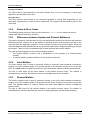
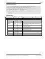
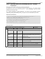
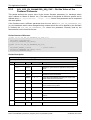
1.5.1.2
9/191
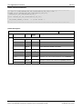
Technical Data (Extended Mode)
In extended mode, the stack offers extended functionality. To use these functions requires an
application program that configures and supports these functions, e.g. to create an own object
dictionary.
In extended mode, more input and output data can be used and transmit and receive PDOs can be
used.
Note: The actual maximum number of IO Data and PDOs depends on the available
amount of memory.
To use the extended mode requires creating a suitable EDS file. The knowledge of the EDS
specification is required.
Features
Parameter
Maximum number of input data
2048 bytes
Maximum number of output data
2048 bytes
Maximum number of receive PDOs
256
Maximum number of transmit PDOs
256
Table 8: Technical Data - Protocol Stack (Extended Mode)
Other settings than default must be set via “Set Configuration Packet” and object dictionary
configuration.
Concerning the extended mode, also see section Standard Mode vs. Extended Mode on page 68.
Note: SYCON.net and netX configuration tool do not support the configuration of the
extended mode.
CANopen Slave | Protocol API
DOC111001API05EN | Revision 5 | English | 2013-10 | Released | Public
© Hilscher, 2011-2013
Introduction
1.6
10/191
Terms, Abbreviations and Definitions
Term
Description
AP
Application on top of the Stack
Boot up
Initial sequence of node during start-up
CAN
Controller Area Network
CAN-DL
CAN Data Link Layer
CiA
CAN in Automation (CAN User Organization located in Erlangen, Germany)
COB-ID
Communication Object Identifier
DPM
Dual Port Memory
EMCY
Emergency
Guarding
Supervision of node
NMT
Network Management
OD
Object Dictionary
ODV3
Object Dictionary Version 3
PDO
Process Data Object (process data channel)
PDO-Mapping
Configurable process data per PDO
RTR
Remote transmission request
RxPDO
Receive PDO
SDO
Service Data Object (representing an acyclic data channel)
SYNC
Synchronization cycle of the CANopen slave
TxPDO
Transmit PDO
Table 9: Terms, Abbreviations and Definitions
All variables, parameters and data used in this manual have basically the LSB/MSB (“Intel”) data
representation. This corresponds to the convention of the Microsoft C Compiler.
1.7
References to Documents
This document refers to the following documents:
[1]
EN 50325/4 Specification
[2]
CAN in Automation e.V., Nuremberg: CANopen Application Layer and Communication
Profile, CiA Public Specification 301, Version 4.2.0, 2011
[3]
Hilscher Gesellschaft für Systemautomation mbH: Dual-Port Memory Interface Manual, netX
based products. Revision 12, English, 2008-2012
[4]
Hilscher Gesellschaft für Systemautomation mbH: Object Dictionary Version 3 Manual, 20082013
[5]
Hilscher Gesellschaft für Systemautomation mbH: CAN Data Link Packet Interface Protocol
API Manual 1.0, 2010-2013
Table 10: References
CANopen Slave | Protocol API
DOC111001API05EN | Revision 5 | English | 2013-10 | Released | Public
© Hilscher, 2011-2013
Introduction
1.8
1.8.1
©
11/191
Legal Notes
Copyright
2008-2013 Hilscher Gesellschaft für Systemautomation mbH
All rights reserved.
The images, photographs and texts in the accompanying material (user manual, accompanying
texts, documentation, etc.) are protected by German and international copyright law as well as
international trade and protection provisions. You are not authorized to duplicate these in whole or
in part using technical or mechanical methods (printing, photocopying or other methods), to
manipulate or transfer using electronic systems without prior written consent. You are not permitted
to make changes to copyright notices, markings, trademarks or ownership declarations. The
included diagrams do not take the patent situation into account. The company names and product
descriptions included in this document may be trademarks or brands of the respective owners and
may be trademarked or patented. Any form of further use requires the explicit consent of the
respective rights owner.
1.8.2
Important Notes
The user manual, accompanying texts and the documentation were created for the use of the
products by qualified experts, however, errors cannot be ruled out. For this reason, no guarantee
can be made and neither juristic responsibility for erroneous information nor any liability can be
assumed. Descriptions, accompanying texts and documentation included in the user manual do
not present a guarantee nor any information about proper use as stipulated in the contract or a
warranted feature. It cannot be ruled out that the user manual, the accompanying texts and the
documentation do not correspond exactly to the described features, standards or other data of the
delivered product. No warranty or guarantee regarding the correctness or accuracy of the
information is assumed.
We reserve the right to change our products and their specification as well as related user
manuals, accompanying texts and documentation at all times and without advance notice, without
obligation to report the change. Changes will be included in future manuals and do not constitute
any obligations. There is no entitlement to revisions of delivered documents. The manual delivered
with the product applies.
Hilscher Gesellschaft für Systemautomation mbH is not liable under any circumstances for direct,
indirect, incidental or follow-on damage or loss of earnings resulting from the use of the information
contained in this publication.
CANopen Slave | Protocol API
DOC111001API05EN | Revision 5 | English | 2013-10 | Released | Public
© Hilscher, 2011-2013
Introduction
1.8.3
12/191
Exclusion of Liability
The software was produced and tested with utmost care by Hilscher Gesellschaft für
Systemautomation mbH and is made available as is. No warranty can be assumed for the
performance and flawlessness of the software for all usage conditions and cases and for the
results produced when utilized by the user. Liability for any damages that may result from the use
of the hardware or software or related documents, is limited to cases of intent or grossly negligent
violation of significant contractual obligations. Indemnity claims for the violation of significant
contractual obligations are limited to damages that are foreseeable and typical for this type of
contract.
It is strictly prohibited to use the software in the following areas:
for military purposes or in weapon systems;
for the design, construction, maintenance or operation of nuclear facilities;
in air traffic control systems, air traffic or air traffic communication systems;
in life support systems;
in systems in which failures in the software could lead to personal injury or injuries leading to
death.
We inform you that the software was not developed for use in dangerous environments requiring
fail-proof control mechanisms. Use of the software in such an environment occurs at your own risk.
No liability is assumed for damages or losses due to unauthorized use.
1.8.4
Export
The delivered product (including the technical data) is subject to export or import laws as well as
the associated regulations of different counters, in particular those of Germany and the USA. The
software may not be exported to countries where this is prohibited by the United States Export
Administration Act and its additional provisions. You are obligated to comply with the regulations at
your personal responsibility. We wish to inform you that you may require permission from state
authorities to export, re-export or import the product.
1.8.5
Registered Trademarks
CANopen® is a registered trademark of CAN in AUTOMATION - International Users and
Manufacturers Group e.V. (CiA), Erlangen.
All other mentioned trademarks are property of their respective legal owners.
CANopen Slave | Protocol API
DOC111001API05EN | Revision 5 | English | 2013-10 | Released | Public
© Hilscher, 2011-2013
Fundamentals
2
13/191
Fundamentals
2.1
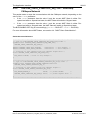
General Access Mechanisms on netX Systems
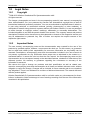
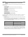
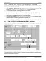
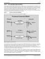
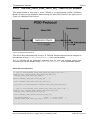
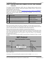
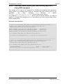
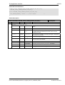
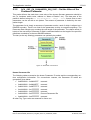
This chapter explains the possible ways to access a Protocol Stack running on a netX system :
1. By accessing the Dual Port Memory Interface directly or via a driver.
2. By accessing the Dual Port Memory Interface via a shared memory.
3. By interfacing with the Stack Task of the Protocol Stack.
The picture below visualizes these three ways:
1
2
(Extended) Status Block
Send Mailbox
Reveive Mailbox
Output Data Image
Input Data Image
AP Task
3
Fieldbus Task(s)
Network Abstraction Layer
Network
Figure 1: The 3 different Ways to access a Protocol Stack running on a netX System
This chapter explains how to program the stack (alternative 3) correctly while the next chapter
describes accessing the protocol stack via the dual-port memory interface according to alternative
1 (and 2, if the user application is executed on the netX chip in the context of the rcX operating
system and uses the virtual DPM). Finally, chapter 5 titled “The Application Interface” describes the
entire interface to the protocol stack in detail.
Depending on you choose the stack-oriented approach or the Dual Port Memory-based approach,
you will need either the information given in this chapter or those of the next chapter to be able to
work with the set of functions described in chapter 5. All of those functions use the four parameters
ulDest, ulSrc, ulDestId and ulSrcId. This chapter and the next one inform about how
to work with these important parameters.
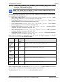
2.2
Accessing the Protocol Stack by Programming the AP
Task’s Queue
In general, programming the AP task or the stack has to be performed according to the rules
explained in the Hilscher Task Layer Reference Manual. There you can also find more information
about the variables discussed in the following.
CANopen Slave | Protocol API
DOC111001API05EN | Revision 5 | English | 2013-10 | Released | Public
© Hilscher, 2011-2013
Fundamentals
2.2.1
14/191
Getting the Receiver Task Handle of the Process Queue
To get the handle of the process queue of the CANopen Slave-Task the Macro
TLR_QUE_IDENTIFY() needs to be used. It is described in detail within section 10.1.9.3 of the
Hilscher Task Layer Reference Model Manual. This macro delivers a pointer to the handle of the
intended queue to be accessed (which is returned within the third parameter, phQue), if you
provide it with the name of the queue (and an instance of your own task). The correct ASCII-queue
name for accessing the CANopen Slave-Task which you have to use as current value for the first
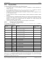
parameter (pszIdn) is
ASCII queue name
Description
“QUE_CANOPENSLV”
Name of the CANopen slave-Task process queue
“QUE_COS_ODV3”
Name of the CANopen slave- Task ODV3 process queue
"QUE_CANOPENAPS”
Name of the APS-Task process queue
“CAN_DL_QUE”
Name of CAN-DL-Task process queue
Table 11: ASCII Queue Name
The returned handle has to be used as value ulDest in all initiator packets the AP-Task intends to
send to the CANopen slave. This handle is the same handle that has to be used in conjunction with
the macros like TLR_QUE_SENDPACKET_FIFO/LIFO() for sending a packet to the respective
task.
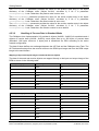
2.2.2
Meaning of Source- and Destination-related Parameters
The meaning of the source- and destination-related parameters is explained in the following table:
Variable
Meaning
ulDest
Application mailbox used for confirmation
ulSrc
Queue handle returned by TLR_QUE_IDENTIFY() as described above.
ulSrcId
Used for addressing at a lower level
Table 12: Meaning of Source- and Destination-related Parameters
For more information about programming the AP task’s stack queue, please refer to the Hilscher
Task Layer Reference Model Manual. Especially the following sections might be of interest in this
context:
1. Section 7 “Queue-Packets”
2. Section 10.1.9 “Queuing Mechanism”
CANopen Slave | Protocol API
DOC111001API05EN | Revision 5 | English | 2013-10 | Released | Public
© Hilscher, 2011-2013
Fundamentals
2.3
15/191
Accessing the Protocol Stack via the Dual Port Memory
Interface
This chapter defines the application interface of the CANopen Slave stack V3.
2.3.1
Communication via Mailboxes
The mailbox of each communication channel has two areas that are used for non-cyclic message
transfer to and from the netX.
Send Mailbox
Packet transfer from host system to firmware
Receive Mailbox
Packet transfer from firmware to host system
For more details about acyclic data transfer via mailboxes see section 3.2. The concept of using
messages called packets in this context, is described in detail in section 3.2.1 “General Structure of
Messages or Packets for Non-Cyclic Data Exchange” while the possible codes that may appear
are listed in section 3.2.2. “Status & Error Codes”.
However, this section concentrates on correct addressing the mailboxes.
CANopen Slave | Protocol API
DOC111001API05EN | Revision 5 | English | 2013-10 | Released | Public
© Hilscher, 2011-2013
Fundamentals
2.3.2
16/191
Using Source and Destination Variables correctly
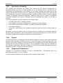
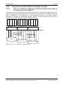
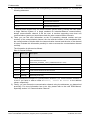
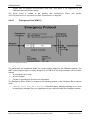
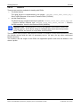
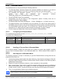
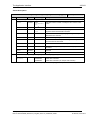
2.3.2.1
How to use ulDest for Addressing rcX and the netX Protocol Stack by
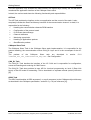
the System and Channel Mailbox
System
Mailbox
Channel 0
Mainbox
ulDest = 0x02
ulDest = 0x01
ulDest = 0x00
ulDest = 0x20
ulDest = 0x02
ulDest = 0x01
ulDest = 0x00
ulDest = 0x20
ulDest = 0x02
ulDest = 0x01
ulDest = 0x00
ulDest = 0x20
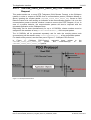
The preferred way to address the netX operating system rcX is through the system mailbox; the
preferred way to address a protocol stack is through its channel mailbox. All mailboxes, however,
have a mechanism to route packets to a communication channel or the system channel,
respectively. Therefore, the destination identifier ulDest in a packet header has to be filled in
according to the targeted receiver. See the following example.
Channel 1
Mailbox
netX OS
rcX
AP Task 1
AP Task 2
Figure 2: Use of ulDest in Channel and System Mailbox
CANopen Slave | Protocol API
DOC111001API05EN | Revision 5 | English | 2013-10 | Released | Public
© Hilscher, 2011-2013
Fundamentals
17/191
For use in the destination queue handle, the tasks have been assigned to hexadecimal numerical
values as described in the following table:
ulDest
Description
0x00000000
Packet is passed to the netX operating system rcX
0x00000001
Packet is passed to communication channel 0
0x00000002
Packet is passed to communication channel 1
0x00000003
Packet is passed to communication channel 2
0x00000004
Packet is passed to communication channel 3
0x00000020
Packet is passed to communication channel of the mailbox
else
Reserved, do not use
Table 13: Destination Queue Handle
The picture and the table above both show the use of the destination identifier ulDest.
A remark on the special channel identifier 0x00000020 (= Channel Token). The Channel Token is
valid for any mailbox. That way the application uses the same identifier for all packets without
actually knowing which mailbox or communication channel is applied. The packet stays 'local'. The
system mailbox is a little bit different, because it is used to communicate to the netX operating
system rcX. The rcX has its own range of valid commands codes and differs from a communication
channel.
Unless there is a reply packet, the netX operating system returns it to the same mailbox the
request packet went through. Consequently, the host application has to return its reply packet to
the mailbox the request was received from.
CANopen Slave | Protocol API
DOC111001API05EN | Revision 5 | English | 2013-10 | Released | Public
© Hilscher, 2011-2013
Fundamentals
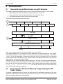
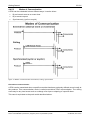
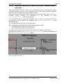
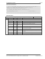
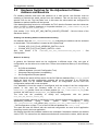
2.3.2.2
18/191
How to use ulSrc and ulSrcId
Generally, a netX protocol stack can be addressed through its communication channel mailbox.
The example below shows how a host application addresses a protocol stack running in the
context of a netX chip. The application is identified by a number (#444 in this example). The
application consists of three processes identified by the numbers #11, #22 and #33. These
processes communicate through the channel mailbox with the AP task of the protocol stack. Have
a look at the following image:
Process #33
Process #22
Process #11
Application #444
Channel
Mainbox
netX Protocol stack
AP Task 1
Figure 3: Using ulSrc and ulSrcId
CANopen Slave | Protocol API
DOC111001API05EN | Revision 5 | English | 2013-10 | Released | Public
© Hilscher, 2011-2013
Fundamentals
19/191
Example:
This example applies to command messages initiated by a process in the context of the host
application. If the process #22 sends a packet through the channel mailbox to the AP task, the
packet header has to be filled in as follows:
Object
Variable
Name
Numeric
Value
Explanation
Destination
Queue Handle
ulDest
= 32
(0x00000020)
This value needs always to be set to 0x00000020 (the channel
token) when accessing the protocol stack via the local
communication channel mailbox.
Source Queue
Handle
ulSrc
= 444
Denotes the host application (#444).
Destination
Identifier
ulDestId
= 0
In this example it is not necessary to use the destination identifier.
Source
Identifier
ulSrcId
= 22
Denotes the process number of the process within the host
application and needs therefore to be supplied by the programmer
of the host application.
Table 14: Using ulSrc and ulSrcId
For packets through the channel mailbox, the application uses 32 (= 0x20, Channel Token) for the
destination queue handler ulDest. The source queue handler ulSrc and the source identifier ulSrcId
are used to identify the originator of a packet. The destination identifier ulDestId can be used to
address certain resources in the protocol stack. It is not used in this example. The source queue
handler ulSrc has to be filled in. Therefore its use is mandatory; the use of ulSrcId is optional.
The netX operating system passes the request packet to the protocol stack's AP task. The protocol
stack then builds a reply to the packet and returns it to the mailbox. The application has to make
sure that the packet finds its way back to the originator (process #22 in the example).
2.3.2.3
How to Route rcX Packets
To route an rcX packet the source identifier ulSrcId and the source queues handler ulSrc in the
packet header hold the identification of the originating process. The router saves the original
handle from ulSrcId and ulSrc. The router uses a handle of its own choices for ulSrcId and ulSrc
before it sends the packet to the receiving process. That way the router can identify the
corresponding reply packet and matches the handle from that packet with the one stored earlier.
Now the router replaces its handles with the original handles and returns the packet to the
originating process.
CANopen Slave | Protocol API
DOC111001API05EN | Revision 5 | English | 2013-10 | Released | Public
© Hilscher, 2011-2013
Fundamentals
2.3.3
20/191
Obtaining useful Information about the Communication
Channel
A communication channel represents a part of the Dual Port Memory and usually consists of the
following elements:
Output Data Image
is used to transfer cyclic process data to the network (normal or high-priority)
Input Data Image
is used to transfer cyclic process data from the network (normal or high-priority)
Send Mailbox
is used to transfer non-cyclic data to the netX
Receive Mailbox
is used to transfer non-cyclic data from the netX
Control Block
allows the host system to control certain channel functions
Common Status Block
holds information common to all protocol stacks
Extended Status Block
holds protocol specific network status information
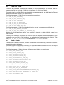
This section describes a procedure how to obtain useful information for accessing the
communication channel(s) of your netX device and to check if it is ready for correct operation.
Proceed as follows:
1) Start with reading the channel information block within the system channel (usually starting
at address 0x0030).
2) Then you should check the hardware assembly options of your netX device. They are
located within the system information block following offset 0x0010 and stored as data type
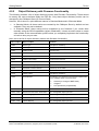
UINT16. The following table explains the relationship between the offsets and the
corresponding xC Ports of the netX device:
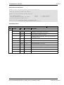
Offset
Port
0x0010
Hardware Assembly Options for xC Port[0]
0x0012
Hardware Assembly Options for xC Port[1]
0x0014
Hardware Assembly Options for xC Port[2]
0x0016
Hardware Assembly Options for xC Port[3]
Check each of the hardware assembly options whether its value has been set to
RCX_HW_ASSEMBLY_CAN = 0x0030. If true, this denotes that this xCPort is suitable for
running the CANopen protocol stack. Otherwise, this port is designed for another
communication protocol. In most cases, xC Port[2] will be used for field-bus systems, while
xC Port[0] and xC Port[1] are normally used for Ethernet communication.
CANopen Slave | Protocol API
DOC111001API05EN | Revision 5 | English | 2013-10 | Released | Public
© Hilscher, 2011-2013
Fundamentals
21/191
3) You can find information about the corresponding communication channel (0…3) under the
following addresses:
Offset
Communication Channel
0x0050
Communication Channel 0
0x0060
Communication Channel 1
0x0070
Communication Channel 2
0x0080
Communication Channel 3
In devices which support only one communication system which is usually the case (either
a single field-bus system or a single standard for Industrial-Ethernet communication),
always communication channel 0 will be used. In devices supporting more than one
communication system you should also check the other communication channels.
4) There you can find such information as the ID (containing channel number and port
number) of the communication channel, the size and the location of the handshake cells,
the overall number of blocks within the communication channel and the size of the channel
in bytes. Evaluate this information precisely in order to access the communication channel
correctly.
The information is delivered as follows:
Size of Channel in Bytes
Address
Data Type
Description
0x0050
UINT8
Channel Type = COMMUNICATION
(must have the fixed value
define RCX_CHANNEL_TYPE_COMMUNICATION = 0x05)
0x0051
UINT8
ID (Channel Number, Port Number)
0x0052
UINT8
Size / Position Of Handshake Cells
0x0053
UINT8
Total Number Of Blocks Of This Channel
0x0054
UINT32
Size Of Channel In Bytes
0x0058
UINT8[8]
Reserved (set to zero)
These addresses correspond to communication channel 0, for communication channels 1,
2 and 3 you have to add an offset of 0x0010, 0x0020 or 0x0030 to the address
values, respectively.
5) Finally, you can access the communication channel using the addresses you determined
previously. For more information how to do this, please refer to the netX DPM Manual,
especially section 3.2 “Communication Channel".
CANopen Slave | Protocol API
DOC111001API05EN | Revision 5 | English | 2013-10 | Released | Public
© Hilscher, 2011-2013
Fundamentals
2.4
22/191
Client/Server Mechanism
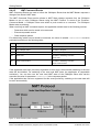
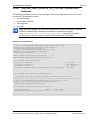
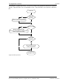
2.4.1
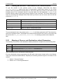
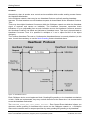
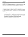
Application as Client
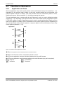
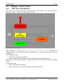
The host application may send request packets to the netX firmware at any time (transition 1 2).
Depending on the protocol stack running on the netX, parallel packets are not permitted (see
protocol specific manual for details). The netX firmware sends a confirmation packet in return,
signaling success or failure (transition 3 4) while processing the request.
The host application has to register with the netX firmware in order to receive indication packets
(transition 5 6). Depending on the protocol stack, this is done either implicit (if application opens
a TCP/UDP socket) or explicit (if application wants to receive unsolicited packets). Details on when
and how to register for certain events is described in the protocol specific manual. Depending on
the command code of the indication packet, a response packet to the netX firmware may or may
not be required (transition 7 8).
Application
netX
Figure 4: Transition Chart Application as Client
The host application sends request packets to the netX firmware.
The netX firmware sends a confirmation packet in return.
The host application receives indication packets from the netX firmware.
The host application sends response packet to the netX firmware (may not be required).
Request
Confirmation
Indication
Response
CANopen Slave | Protocol API
DOC111001API05EN | Revision 5 | English | 2013-10 | Released | Public
© Hilscher, 2011-2013
Fundamentals
2.4.2
23/191
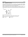
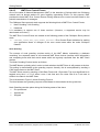
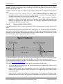
Application as Server
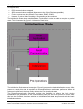
The host application has to register with the netX firmware in order to receive indication packets.
Depending on the protocol stack, this is done either implicit (if application opens a TCP/UDP
socket) or explicit (if application wants to receive unsolicited packets). Details on when and how to
register for certain events is described in the protocol specific manual.
When an appropriate event occurs and the host application is registered to receive such a
notification, the netX firmware passes an indication packet through the mailbox (transition 1 2).
The host application is expected to send a response packet back to the netX firmware (transition 3
4).
Application
netX
Figure 5: Transition Chart Application as Server
The netX firmware passes an indication packet through the mailbox.
The host application sends response packet to the netX firmware.
Indication
Response
CANopen Slave | Protocol API
DOC111001API05EN | Revision 5 | English | 2013-10 | Released | Public
© Hilscher, 2011-2013
Dual-Port-Memory
3
24/191
Dual-Port-Memory
All data in the dual-port memory is structured in blocks. According to their functions, these blocks
use different data transfer mechanisms. For example, data transfer through mailboxes uses a
synchronized handshake mechanism between host system and netX firmware. The same is true
for IO data images, when a buffered handshake mode is configured. Other blocks, like the status
block, are read by the host application and use no synchronization mechanism.
Types of blocks in the dual-port memory are outlined below:
3.1
Mailbox
transfer non-cyclic messages or packages with a header for routing information
Data Area
holds the process image for cyclic IO data or user defined data structures
Control Block
is used to signal application related state to the netX firmware
Status Block
holds information regarding the current network state
Change of State
collection of flags, that initiate execution of certain commands or signal a change of state
Cyclic Data (Input/Output Data)
The input block holds the process data image received from the network whereas the output block
holds data sent to the network.
Process data transfer through the data blocks can be synchronized by using a handshake
mechanism (configurable). If in uncontrolled mode, the protocol stack updates the process data in
the input and output data image in the dual-port memory for each valid bus cycle. No handshake
bits are evaluated and no buffers are used. The application can read or write process data at any
given time without obeying the synchronization mechanism otherwise carried out via handshake
location. This transfer mechanism is the simplest method of transferring process data between the
protocol stack and the application. This mode can only guarantee data consistency over a byte.
For the controlled / buffered mode, the protocol stack updates the process data in the internal input
buffer for each valid bus cycle. Each IO block uses handshake bits for access synchronization.
Input and output data block handshake operates independently from each other. When the
application toggles the input handshake bit, the protocol stack copies the data from the internal
buffer into the input data image of the dual-port memory. Now the application can copy data from
the dual-port memory and then give control back to the protocol stack by toggling the appropriate
input handshake bit. When the application/driver toggles the output handshake bit, the protocol
stack copies the data from the output data image of the dual-port memory into the internal buffer.
From there the data is transferred to the network. The protocol stack toggles the handshake bits
back, indicating to the application that the transfer is finished and a new data exchange cycle may
start. This mode guarantees data consistency over both input and output area.
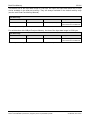
3.1.1
Input Data Image
The input data block is used by field bus and industrial Ethernet protocols that utilize a cyclic data
exchange mechanism. The input data image is used to transfer cyclic data from the network.
CANopen Slave | Protocol API
DOC111001API05EN | Revision 5 | English | 2013-10 | Released | Public
© Hilscher, 2011-2013
Dual-Port-Memory
25/191
The default size of the input data image is 5760 byte. An output and input data block may or may
not be available in the dual-port memory. They are always available in the default memory map
(see the netX Dual-Port Memory Manual).
Input Data Image
Offset
Type
Name
Description
0x2680
UINT8
abPd0Input[5760]
Input Data Image
Cyclic Data From The Network
Table 15: Input Data Image
For netX devices with 8 kByte Dual-port Memory, the size of the input data image is 1536 byte:
Input Data Image
Offset
Type
Name
Description
0x1600
UINT8
abPd0Input[1536]
Input Data Image
Cyclic Data From The Network
Table 16: Input Data Image for netX devices with 8 kByte Dual-port Memory
CANopen Slave | Protocol API
DOC111001API05EN | Revision 5 | English | 2013-10 | Released | Public
© Hilscher, 2011-2013
Dual-Port-Memory
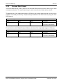
3.1.2
26/191
Process Data Output
The output data block is used by field bus and industrial Ethernet protocols that utilize a cyclic data
exchange mechanism. The output data Image is used to transfer cyclic data to the network.
The default size of the output data image is 5760 byte. An output data block may or may not be
available in the dual-port memory. They are always available in the default memory map (see netX
DPM Manual).
Output Data Image
Offset
Type
Name
Description
0x1000
UINT8
abPd0Output[5760]
Output Data Image
Cyclic Data To The Network
Table 17: Output Data Image
For netX devices with 8 kByte Dual-port Memory, the size of the output data image is 1536 byte:
Output Data Image
Offset
Type
Name
Description
0x1000
UINT8
abPd0Output[1536]
Output Data Image
Cyclic Data To The Network
Table 18: Output Data Image for netX devices with 8 kByte Dual-port Memory
CANopen Slave | Protocol API
DOC111001API05EN | Revision 5 | English | 2013-10 | Released | Public
© Hilscher, 2011-2013
Dual-Port-Memory
3.2
27/191
Acyclic Data (Mailboxes)
The mailbox of each communication channel has two areas that are used for non-cyclic message
transfer.
Send Mailbox
Packet transfer from host system to firmware
Receive Mailbox
Packet transfer from firmware to host system
The send and receive mailbox areas are used by field bus protocols providing a non-cyclic data
exchange mechanism. Another use of the mailbox system is to allow access to the firmware
running on the netX chip itself for diagnostic and identification purposes. The send mailbox is used
to transfer cyclic data to the network or to the firmware. The receive mailbox is used to transfer
cyclic data from the network or from the firmware.
A send/receive mailbox may or may not be available in the communication channel. It depends on
the function of the firmware whether or not a mailbox is needed. The location of the system
mailbox and the channel mailbox is described in the netX DPM Interface Manual.
Note: Each mailbox can hold one packet at a time. The netX firmware stores packets that
are not retrieved by the host application in a packet queue. This queue has limited space
and may fill up so new packets maybe lost. To avoid these deadlock situations, it is
strongly recommended to empty the mailbox frequently, even if packets are not expected
by the host application. Unexpected command packets should be returned to the sender
with an Unknown Command in the status field; unexpected reply messages can be
discarded.
CANopen Slave | Protocol API
DOC111001API05EN | Revision 5 | English | 2013-10 | Released | Public
© Hilscher, 2011-2013
Dual-Port-Memory
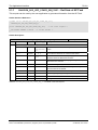
3.2.1
28/191
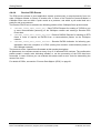
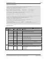
General Structure of Messages or Packets for Non-Cyclic Data
Exchange
The non-cyclic packets through the netX mailbox have the following structure:
Structure Information
Area
Variable
tHead
Structure Information
tData
Type
Value / Range
Description
ulDest
UINT32
Destination Queue Handle
ulSrc
UINT32
Source Queue Handle
ulDestId
UINT32
Destination Queue Reference
ulSrcId
UINT32
Source Queue Reference
ulLen
UINT32
Packet Data Length (In Bytes)
ulId
UINT32
Packet Identification As Unique Number
ulSta
UINT32
Status / Error Code
ulCmd
UINT32
Command / Response
ulExt
UINT32
Reserved
ulRout
UINT32
Routing Information
Structure Information
…
…
User Data
Specific To The Command
Table 19: General Structure of Messages or Packets for Non-Cyclic Data Exchange
Some of the fields are mandatory; some are conditional; others are optional. However, the size of a
packet is always at least 10 double-words or 40 bytes. Depending on the command, a packet may
or may not have a data field. If present, the content of the data field is specific to the command,
respectively the reply.
Destination Queue Handler
The ulDest field identifies a task queue in the context of the netX firmware. The task queue
represents the final receiver of the packet and is assigned to a protocol stack. The ulDest field has
to be filled out in any case. Otherwise, the netX operating system cannot route the packet. This
field is mandatory.
Source Queue Handler
The ulSrc field identifies the sender of the packet. In the context of the netX firmware (inter-task
communication) this field holds the identifier of the sending task. Usually, a driver uses this field for
its own handle, but it can hold any handle of the sending process. Using this field is mandatory.
The receiving task does not evaluate this field and passes it back unchanged to the originator of
the packet.
CANopen Slave | Protocol API
DOC111001API05EN | Revision 5 | English | 2013-10 | Released | Public
© Hilscher, 2011-2013
Dual-Port-Memory
29/191
Destination Identifier
The ulDestId field identifies the destination of an unsolicited packet from the netX firmware to the
host system. It can hold any handle that helps to identify the receiver. Therefore, its use is
mandatory for unsolicited packets. The receiver of unsolicited packets has to register for this.
Source Identifier
The ulSrcId field identifies the originator of a packet. This field is used by a host application, which
passes a packet from an external process to an internal netX task. The ulSrcId field holds the
handle of the external process. When netX operating system returns the packet, the application
can identify the packet and returns it to the originating process. The receiving task on the netX
does not evaluate this field and passes it back unchanged. For inter-task communication, this field
is not used.
Length of Data Field
The ulLen field holds the size of the data field in bytes. It defines the total size of the packet’s
payload that follows the packet’s header. The size of the header is not included in ulLen. So the
total size of a packet is the size from ulLen plus the size of packet’s header. Depending on the
command, a data field may or may not be present in a packet. If no data field is included, the
length field is set to zero.
Identifier
The ulId field is used to identify a specific packet among others of the same kind. That way the
application or driver can match a specific reply or confirmation packet to a previous request packet.
The receiving task does not change this field and passes it back to the originator of the packet. Its
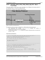
use is optional in most of the cases. But it is mandatory for sequenced packets. Example:
Downloading big amounts of data that does not fit into a single packet. For a sequence of packets
the identifier field is incremented by one for every new packet.
Status / Error Code
The ulState field is used in response or confirmation packets. It informs the originator of the packet
about success or failure of the execution of the command. The field may be also used to hold
status information in a request packet.
Command / Response
The ulCmd field holds the command code or the response code, respectively. The
command/response is specific to the receiving task. If a task is not able to execute certain
commands, it will return the packet with an error indication. A command is always even (the least
significant bit is zero). In the response packet, the command code is incremented by one indicating
a confirmation to the request packet.
Extension
The extension field ulExt is used for controlling packets that are sent in a sequenced manner. The
extension field indicates the first, last or a packet of a sequence. If sequencing is not required, the
extension field is not used and set to zero.
CANopen Slave | Protocol API
DOC111001API05EN | Revision 5 | English | 2013-10 | Released | Public
© Hilscher, 2011-2013
Dual-Port-Memory
30/191
Routing Information
The ulRout field is used internally by the netX firmware only. It has no meaning to a driver type
application and therefore set to zero.
User Data Field
This field contains data related to the command specified in ulCmd field. Depending on the
command, a packet may or may not have a data field. The length of the data field is given in the
ulLen field.
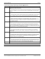
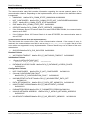
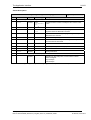
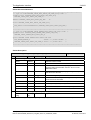
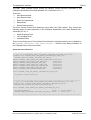
3.2.2
Status & Error Codes
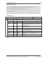
The following status and error codes can be returned in ulState: List of codes see manual
named netX Dual-Port Memory Interface.
3.2.3
Differences between System and Channel Mailboxes
The mailbox system on netX provides a non-cyclic data transfer channel for field bus and industrial
Ethernet protocols. Another use of the mailbox is allowing access to the firmware running on the
netX chip itself for diagnostic purposes. There is always a send and a receive mailbox. Send and
receive mailboxes utilize handshake bits to synchronize these data or diagnostic packages through
the mailbox. There is a pair of handshake bits for both the send and receive mailbox.
The netX operating system rcX only uses the system mailbox.
The system mailbox, however, has a mechanism to route packets to a communication
channel.
A channel mailbox passes packets to its own protocol stack only.
3.2.4
Send Mailbox
The send mailbox area is used by protocols utilizing a non-cyclic data exchange mechanism.
Another use of the mailbox system is to provide access to the firmware running on the netX chip
itself. The send mailbox is used to transfer non-cyclic data to the network or to the protocol stack.
The size is 1596 bytes for the send mailbox in the default memory layout. The mailbox is
accompanied by counters that hold the number of packages that can be accepted.
3.2.5
Receive Mailbox
The receive mailbox area is used by protocols utilizing a non-cyclic data exchange mechanism.
Another use of the mailbox system is to provide access to the firmware running on the netX chip
itself. The receive mailbox is used to transfer non-cyclic data from the network or from the
protocol stack.
The size is 1596 bytes for the receive mailbox in the default memory layout. The mailbox is
accompanied by counters that hold the number of waiting packages (for the receive mailbox).
CANopen Slave | Protocol API
DOC111001API05EN | Revision 5 | English | 2013-10 | Released | Public
© Hilscher, 2011-2013
Dual-Port-Memory
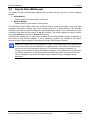
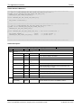
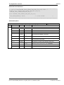
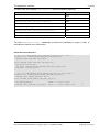
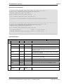
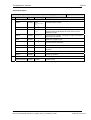
3.2.6
31/191
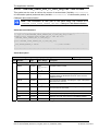
Channel Mailboxes (Details of Send and Receive Mailboxes)
Master Status
Offset
Type
Name
Description
0x0200
UINT16
usPackagesAccepted
Packages Accepted
Number of Packages that can
be Accepted
0x0202
UINT16
usReserved
Reserved
Set to 0
0x0204
UINT8[]
abSendMbx[1596]
Send Mailbox
Non Cyclic Data To The
Network or to the Protocol
Stack
0x0840
UINT16
usWaitingPackages
Packages waiting
Counter of packages that are
waiting to be processed
0x0842
UINT16
usReserved
Reserved
Set to 0
0x0844
UINT8
abRecvMbx[1596]
Receive Mailbox
Non Cyclic Data from the
network or from the
protocol stack
Table 20: Channel Mailboxes
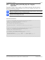
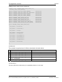
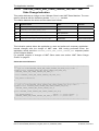
Channel Mailboxes Structure
typedef struct tagNETX_SEND_MAILBOX_BLOCK
{
UINT16 usPackagesAccepted;
UINT16 usReserved;
UINT8 abSendMbx[1596];
} NETX_SEND_MAILBOX_BLOCK;
typedef struct tagNETX_RECV_MAILBOX_BLOCK
{
UINT16 usWaitingPackages;
UINT16 usReserved;
UINT8 abRecvMbx[1596];
}NETX_RECV_MAILBOX_BLOCK;
CANopen Slave | Protocol API
DOC111001API05EN | Revision 5 | English | 2013-10 | Released | Public
© Hilscher, 2011-2013
Dual-Port-Memory
3.3
32/191
Status
A status block is present within the communication channel. It contains information about network
and task related issues. In some respects, status and control block are used together in order to
exchange information between host application and netX firmware. The application reads a status
block whereas the control block is written by the application. Both status and control block have
registers that use the Change of State mechanism (see also section 2.2.1 of the netX Dual-PortMemory manual).
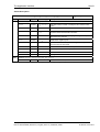
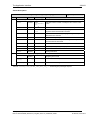
3.3.1
Common Status
The Common Status Block contains information that is the same for all communication channels.
The start offset of this block depends on the size and location of the preceding blocks. The status
block is always present in the dual-port memory.
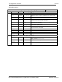
3.3.1.1
All Implementations
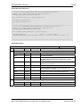
The structure outlined below is common to all protocol stacks.
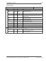
Common Status Structure Definition
Common Status
Offset
Type
Name
Description
0x0010
UINT32
ulCommunicationCOS
Communication Change of
State
READY, RUN, RESET
REQUIRED, NEW, CONFIG
AVAILABLE, CONFIG
LOCKED
0x0014
UINT32
ulCommunicationState
Communication State
NOT CONFIGURED, STOP,
IDLE, OPERATE
0x0018
UINT32
ulCommunicationError
Communication Error
Unique Error Number
According to Protocol Stack
0x001C
UINT16
usVersion
Version
Version Number of this
Diagnosis Structure
0x001E
UINT16
usWatchdogTime
Watchdog Timeout
Configured Watchdog Time
0x0020
UINT16
usHandshakeMode
0x0022
UINT16
usReserved
Reserved
Set to 0
0x0024
UINT32
ulHostWatchdog
Host Watchdog
Handshake Mode
Process Data Transfer Mode
(see netX DPM Interface
Manual)
Joint Supervision Mechanism
Protocol Stack Writes, Host
System Reads
CANopen Slave | Protocol API
DOC111001API05EN | Revision 5 | English | 2013-10 | Released | Public
© Hilscher, 2011-2013
Dual-Port-Memory
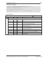
33/191
UINT32
0x0028
ulErrorCount
Error Count
Total Number of Detected
Errors Since Power-Up or
Reset
UINT32
0x002C
ulErrorLoglnd
Error Log Indicator
Total Number Of Entries In The
Error Log
Structure (not supported yet)
UINT32
0x0030
ulReserved[2]
Reserved
Set to 0
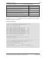
Table 21: Common Status Structure Definition
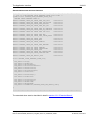
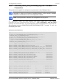
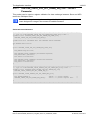
Common Status Block Structure Reference
typedef struct NETX_COMMON_STATUS_BLOCK_Ttag
{
UINT32 ulCommunicationCOS;
UINT32 ulCommunicationState;
UINT32 ulCommunicationError;
UINT16 usVersion;
UINT16 usWatchdogTime;
UINT16 ausReserved[2];
UINT32 ulHostWatchdog;
UINT32 ulErrorCount;
UINT32 ulErrorLogInd;
UINT32 ulReserved[2];
union
{
NETX_MASTER_STATUS_T tMasterStatus;
/* for master implementation */
UINT32
aulReserved[6];
/* otherwise reserved
*/
} unStackDepended;
} NETX_COMMON_STATUS_BLOCK_T;
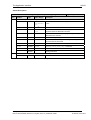
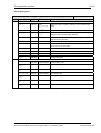
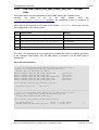
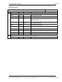
Communication Change of State (All Implementations)
The communication change of state register contains information about the current operating
status of the communication channel and its firmware. Every time the status changes, the netX
protocol stack toggles the netX Change of State Command flag in the netX communication flags
register (see section 3.2.2.1 of the netX DPM Interface Manual). The application then has to toggle
the netX Change of State Acknowledge flag back acknowledging the new state (see section
3.2.2.2 of the netX DPM Interface Manual).
ulCommunicationCOS - netX writes, Host reads
Bit
Short name
Name
D31 .. D7
unused, set to zero
D6
Restart Required Enable
RCX_COMM_COS_RESTART_REQUIRED_ENABLE
D5
Restart Required
RCX_COMM_COS_RESTART_REQUIRED
D4
Configuration New
RCX_COMM_COS_CONFIG_NEW
D3
Configuration Locked
RCX_COMM_COS_CONFIG_LOCKED
D2
Bus On
RCX_COMM_COS_BUS_ON
D1
Running
RCX_COMM_COS_RUN
D0
Ready
RCX_COMM_COS_READY
Table 22: Communication State of Change
CANopen Slave | Protocol API
DOC111001API05EN | Revision 5 | English | 2013-10 | Released | Public
© Hilscher, 2011-2013
Dual-Port-Memory
34/191
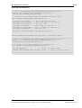
Communication Change of State Flags (netX System Application)
Bit
0
Definition / Description
Ready (RCX_COMM_COS_READY)
0-…
1 - The Ready flag is set as soon as the protocol stack is started properly. Then the protocol stack is
awaiting a configuration. As soon as the protocol stack is configured properly, the Running flag is
set, too.
1
Running (RCX_COMM_COS_RUN)
0-…
1 -The Running flag is set when the protocol stack has been configured properly. Then the protocol
stack is awaiting a network connection. Now both the Ready flag and the Running flag are set.
2
Bus On (RCX_COMM_COS_BUS_ON)
0-…
1 -The Bus On flag is set to indicate to the host system whether or not the protocol stack has the
permission to open network connections. If set, the protocol stack has the permission to
communicate on the network; if cleared, the permission was denied and the protocol stack will not
open network connections.
3
Configuration Locked (RCX_COMM_COS_CONFIG_LOCKED)
0-…
1 -The Configuration Locked flag is set, if the communication channel firmware has locked the
configuration database against being overwritten. Re-initializing the channel is not allowed in this
state. To unlock the database, the application has to clear the Lock Configuration flag in the control
block (see section 3.2.4 of the netX DPM Interface Manual).
4
Configuration New (RCX_COMM_COS_CONFIG_NEW)
0-…
1 -The Configuration New flag is set by the protocol stack to indicate that a new configuration
became available, which has not been activated. This flag may be set together with the Restart
Required flag.
5
Restart Required (RCX_COMM_COS_RESTART_REQUIRED)
0-…
1 -The Restart Required flag is set when the channel firmware requests to be restarted. This flag is
used together with the Restart Required Enable flag below. Restarting the channel firmware may
become necessary, if a new configuration was downloaded from the host application or if a
configuration upload via the network took place.
6
Restart Required Enable (RCX_COMM_COS_RESTART_REQUIRED_ENABLE)
0-…
1 - The Restart Required Enable flag is used together with the Restart Required flag above. If set,
this flag enables the execution of the Restart Required command in the netX firmware (for details on
the Enable mechanism see section 2.3.2 of the netX DPM Interface Manual)).
7 … 31
Reserved, set to 0
Table 23: Meaning of Communication Change of State Flags
Other values are reserved.
CANopen Slave | Protocol API
DOC111001API05EN | Revision 5 | English | 2013-10 | Released | Public
© Hilscher, 2011-2013
Dual-Port-Memory
35/191
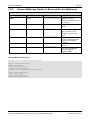
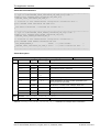
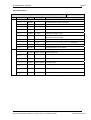
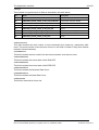
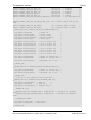
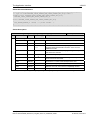
Communication State (All Implementations)
The communication state field contains information regarding the current network status of the
communication channel. Depending on the implementation, all or a subset of the definitions below
is supported.
UNKNOWN
#define RCX_COMM_STATE_UNKNOWN 0x00000000
NOT_CONFIGURED #define RCX_COMM_STATE_NOT_CONFIGURED 0x00000001
STOP
IDLE #define RCX_COMM_STATE_IDLE 0x00000003
OPERATE #define RCX_COMM_STATE_OPERATE 0x00000004
If the CANopen Slave V3 Protocol Stack is in state PRE-OPERATIONAL, the communication
state is set to IDLE.
If the CANopen Slave V3 Protocol Stack is in state STOPPED, the communication state is
set to STOP.
#define RCX_COMM_STATE_STOP 0x00000002
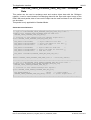
Communication Channel Error (All Implementations)
This field holds the current error code of the communication channel. If the cause of error is
resolved, the communication error field is set to zero (= RCX_SYS_SUCCESS) again. Not all of the
error codes are supported in every implementation. Protocol stacks may use a subset of the error
codes below.
SUCCESS #define RCX_SYS_SUCCESS 0x00000000
Runtime Failures
WATCHDOG TIMEOUT #define RCX_E_WATCHDOG_TIMEOUT 0xC000000C
Initialization Failures
(General) INITIALIZATION FAULT
#define RCX_E_INIT_FAULT
0xC0000100
DATABASE ACCESS FAILED #define RCX_E_DATABASE_ACCESS_FAILED
0xC0000101
Configuration Failures
NOT CONFIGURED
#define RCX_E_NOT_CONFIGURED
(General) CONFIGURATION FAULT
#define RCX_E_CONFIGURATION_FAULT
0xC0000119
0xC0000120
INCONSISTENT DATA SET #define RCX_E_INCONSISTENT_DATA_SET
0xC0000121
DATA SET MISMATCH
INSUFFICIENT LICENSE #define RCX_E_INSUFFICIENT_LICENSE
0xC0000123
PARAMETER ERROR #define RCX_E_PARAMETER_ERROR 0xC0000124
INVALID NETWORK ADDRESS
0xC0000125
NO SECURITY MEMORY#define RCX_E_NO_SECURITY_MEMORY
#define RCX_E_DATA_SET_MISMATCH 0xC0000122
#define RCX_E_INVALID_NETWORK_ADDRESS
CANopen Slave | Protocol API
DOC111001API05EN | Revision 5 | English | 2013-10 | Released | Public
0xC0000126
© Hilscher, 2011-2013
Dual-Port-Memory
36/191
Network Failures
(General) NETWORK FAULT
#define RCX_COMM_NETWORK_FAULT 0xC0000140
CONNECTION CLOSED #define RCX_COMM_CONNECTION_CLOSED 0xC0000141
CONNECTION TIMED OUT #define RCX_COMM_CONNECTION_TIMEOUT 0xC0000142
LONELY NETWORK #define RCX_COMM_LONELY_NETWORK
DUPLICATE NODE #define RCX_COMM_DUPLICATE_NODE 0xC0000144
CABLE DISCONNECT #define RCX_COMM_CABLE_DISCONNECT 0xC0000145
0xC0000143
Version (All Implementations)
The version field holds version of this structure. It starts with one; zero is not defined.
STRUCTURE VERSION #define RCX_STATUS_BLOCK_VERSION 0x0001
Watchdog Timeout (All Implementations)
This field holds the configured watchdog timeout value in milliseconds. The application may set its
watchdog trigger interval accordingly. If the application fails to copy the value from the host
watchdog location to the device watchdog location, the protocol stack will interrupt all network
connections immediately regardless of their current state. For details, see section 4.13 of the netX
DPM Interface Manual.
Host Watchdog (All Implementations)
The protocol stack supervises the host system using the watchdog function. If the application fails
to copy the value from the device watchdog location (section 3.2.5 of the netX DPM Interface
Manual) to the host watchdog location (section 3.2.4 of the netX DPM Interface Manual), the
protocol stack assumes that the host system has some sort of problem and shuts down all network
connections. For details on the watchdog function, refer to section 4.13 of the netX DPM Interface
Manual.
Error Count (All Implementations)
This field holds the total number of errors detected since power-up, respectively after reset. The
protocol stack counts all sorts of errors in this field no matter if they were network related or caused
internally.
Error Log Indicator (All Implementations)
The error log indicator field holds the number of entries in the internal error log. If all entries are
read from the log, the field is set to zero. The error log indicator is not supported yet.
3.3.1.2
Master Implementation
The master contains additional structures for the administration of all slaves which are connected
to the master. These are not discussed here as they are not relevant for the slave.
3.3.1.3
Slave Implementation
The slave firmware uses only the common structure as outlined in section 3.2.5.1 of the Hilscher
netX Dual-Port-Memory Manual.
CANopen Slave | Protocol API
DOC111001API05EN | Revision 5 | English | 2013-10 | Released | Public
© Hilscher, 2011-2013
Dual-Port-Memory
3.3.2
37/191
Extended Status
The content of the channel specific extended status block is specific to the implementation.
Depending on the protocol, a status area may or may not be present in the dual-port memory. It is
always available in the default memory map (see section 3.2.1 of netX Dual-Port Memory Manual).
Note: Have in mind, that all offsets mentioned in this section are relative to the beginning
of the common status block, as the start offset of this block depends on the size and
location of the preceding blocks.
Extended Status Block
Offset
Type
Name
Description
0x0050
UINT8[ ]
abExtendedStatus[432]
Extended Status Area
Protocol Stack Specific Status
Area
Table 24: Extended Status Block (General Structure)
Extended Status Block Structure
typedef struct CANOPEN_SLAVE_EXTENDED_STATE_Ttag
CANOPEN_SLAVE_EXTENDED_STATE_T;
#define
#define
#define
#define
#define
#define
#define
#define
#define
#define
CANOPEN_SLAVE_EXT_STATE_FLAG_CAN_INIT
CANOPEN_SLAVE_EXT_STATE_FLAG_CAN_ACTIVE
CANOPEN_SLAVE_EXT_STATE_FLAG_PASSIVE
CANOPEN_SLAVE_EXT_STATE_FLAG_BUS_OFF
CANOPEN_SLAVE_EXT_STATE_FLAG_RX_OVERFLOW
CANOPEN_SLAVE_EXT_STATE_FLAG_TX_OVERFLOW
CANOPEN_SLAVE_EXT_STATE_FLAG_WDG
CANOPEN_SLAVE_EXT_STATE_CTRL
CANOPEN_SLAVE_EXT_STATE_NRDY
CANOPEN_SLAVE_EXT_STATE_TIMEOUT
0x00000001L
0x00000002L
0x00000004L
0x00000008L
0x00000010L
0x00000020L
0x00000100L
0x00001000L
0x00002000L
0x00004000L
#define
#define
#define
#define
#define
CANOPEN_SLAVE_EXT_STATE_UNKNOWN
CANOPEN_SLAVE_EXT_STATE_OPERATIONAL
CANOPEN_SLAVE_EXT_STATE_STOP
CANOPEN_SLAVE_EXT_STATE_PRE_OPERATIONAL
CANOPEN_SLAVE_EXT_STATE_INITIALISING
0x00000000L
0x00000001L
0x00000002L
0x00000080L
0x000000FFL
#define CANOPEN_SLAVE_ADD_DETAIL_SIZE
0x00000003L
struct CANOPEN_SLAVE_EXTENDED_STATE_Ttag
{
TLR_UINT32 ulFlags;
TLR_UINT32 ulNodeState;
TLR_UINT32 ulBusOffEveCnt;
TLR_UINT32 ulErrorPassiveEveCnt;
TLR_UINT32 ulRxOverflowCnt;
TLR_UINT32 ulTxOverflowCnt;
TLR_UINT32 ulReserved;
TLR_UINT32 ulTimeoutCnt;
TLR_UINT32 aulReserved[4];
TLR_UINT32
TLR_UINT32
TLR_UINT32
TLR_UINT32
TLR_UINT32
};
ulDiagInfoCount;
ulLastDiagInfo;
ulMaxRecvIdx;
ulMaxSendIdx;
aulAddDetail[CANOPEN_SLAVE_ADD_DETAIL_SIZE];
CANopen Slave | Protocol API
DOC111001API05EN | Revision 5 | English | 2013-10 | Released | Public
© Hilscher, 2011-2013
Dual-Port-Memory
3.3.2.1
38/191
Extended Status Block
Additional Info Block for CANopen Slave
Offset
Type
Name
Description
0x50
unsigned long
ulFlags
Bit field for Flags
0x54
unsigned long
ulNodeState
Current Node State
0x58
unsigned long
ulBusOffEveCnt
Counter for bus off events
0x5C
unsigned long
ulErrorPassiveEveCnt
Counter for passive event errors
0x60
unsigned long
ulRxOverflowCnt
Counter for receive overflows
0x64
unsigned long
ulTxOverflowCnt
Counter for transmit overflows
0x68
unsigned long
ulErrorWarningCnt
Count of errors and Warnings
0x6C
unsigned long
ulTimeoutCnt
Number of timeouts
0x70
unsigned long[]
aulReserved[3]
Reserved for further use
0x7C
unsigned long
ulIndLostCnt
Count of Lost Indications
0x80
unsigned long
ulDiagInfoCount
Number of diagnostic entries
0x84
unsigned long
ulLastDiagInfo
Last diagnostic entry
0x88
unsigned long
ulMaxRecvIdx
Maximum Object Index Value for Receive Data
0x8C
unsigned long
ulMaxSendIdx
Maximum Object Index Value for Send Data
0x90
unsigned long[]
aulAddDetail[3]
Additional detail for diagnostic entry
Table 25: Additional Info Block
CANopen Slave | Protocol API
DOC111001API05EN | Revision 5 | English | 2013-10 | Released | Public
© Hilscher, 2011-2013
Dual-Port-Memory
39/191
ulFlags
This variable is organized as a bit field as described in the table below:
Bit
Name
Description
D31..
D17
Reserved
Reserved for further use
D16
CANOPEN_SLAVE_EXT_STATE_
FLAG_WARNING
A warning has been issued
D15
Reserved
Reserved for further use
D14
CANOPEN_SLAVE_EXT_STATE_
TIMEOUT
The DEVICE has detected an overstepped timeout supervision time
of at least one CAN message to be sent. The transmission of this
message was aborted. The data is lost. Its an indication that no
other CAN device was connected or responsive at this time to
acknowledge the sent message requests. The bit will be set when
the first timeout was detected and will not be deleted any more.
D13
CANOPEN_SLAVE_EXT_STATE_
NRDY
Indicates if the HOST program has set its state to operative or not.
If the bit is set the HOST program is not ready to communicate.
D12
CANOPEN_SLAVE_EXT_STATE_
CTRL
Parameterization error or severe run time error
D11..
D10
Reserved
Reserved for further use
D9
CANOPEN_SLAVE_EXT_STATE_
FLAG_SLAVE_ERROR
An error has been issued from the slave
D8
CANOPEN_SLAVE_EXT_STATE_
FLAG_WDG
Watchdog error detected
D7
Reserved
Reserved for further use
D6
CANOPEN_SLAVE_EXT_STATE_
FLAG_IND_LOST
Indication has been lost
D5
CANOPEN_SLAVE_EXT_STATE_
FLAG_TX_OVERFLOW
Transmit overflow detected
D4
CANOPEN_SLAVE_EXT_STATE_
FLAG_RX_OVERFLOW
Receive overflow detected
D3
CANOPEN_SLAVE_EXT_STATE_
FLAG_BUS_OFF
CAN is in Bus-off state
D2
CANOPEN_SLAVE_EXT_STATE_
FLAG_PASSIVE
CAN is in error passive state
D1
CANOPEN_SLAVE_EXT_STATE_
FLAG_CAN_ACTIVE
CAN is activated
D0
CANOPEN_SLAVE_EXT_STATE_
FLAG_CAN_INIT
CAN is initialized
Table 26: Additional Info Flags
ulNodeState
Internal node state of node:
0: Unknown state
1: Operational state
2: Stop
128: Pre-operational state
255: Initializing
CANopen Slave | Protocol API
DOC111001API05EN | Revision 5 | English | 2013-10 | Released | Public
© Hilscher, 2011-2013
Dual-Port-Memory
40/191
ulBusOffEveCnt
Number of Bus-off events
ulErrorPassiveEveCnt
Number of error passive events
ulRxOverflowCnt
Number of receive overrun events
ulTxOverflowCnt
Number of transmit overrun events
ulErrorWarningCnt
Total count of errors and warnings
ulTimeoutCnt
Each CAN message is supervised by the card to be sent during 20ms by the CAN chip. If not
possible, because the chip for example gets no acknowledging partner on the bus, this counter is
incremented by one.
aulReserved[ ]
Reserved for further use
ulIndLostCnt
Count of lost indications
ulDiagInfoCount
Number of diagnostic entries
ulLastDiagInfo
Last diagnostic entry
ulMaxRecvIdx
Number of highest PDO mapped receive object index
ulMaxSendIdx
Number of highest PDO mapped send object index
aulAddDetail[ ]
Additional detail for diagnostic entry
CANopen Slave | Protocol API
DOC111001API05EN | Revision 5 | English | 2013-10 | Released | Public
© Hilscher, 2011-2013
Dual-Port-Memory
41/191
3.4 Control Block
A control block is always present in both system and communication channel. In some respects,
control and status block are used together in order to exchange information between host
application and netX firmware. The control block is written by the application, whereas the
application reads a status block. Both control and status block have registers that use the Change
of State mechanism (see section 0).
The following gives an example of the use of control and status block. The host application wishes
to lock the configuration settings of a communication channel to protect them against changes. The
application sets the Lock Configuration flag in the control block to the communication channel
firmware. As a result, the channel firmware sets the Configuration Locked flag in the status block
(see below), indicating that the current configuration settings cannot be deleted, altered,
overwritten or otherwise changed.
The control block of a dual-port memory features a watchdog function to allow the operating
system running on the netX supervise the host application and vice versa. The control area is
always present in the dual-port memory.
Control Block
Offset
Type
Name
Description
0x0008
UINT32
ulApplicationCOS
Application Change Of State
State Of The Application
Program
INITIALIZATION, LOCK
CONFIGURATION
0x000C
UINT32
ulDeviceWatchdog
Device Watchdog
Host System Writes, Protocol
Stack Reads
Table 27: Communication Control Block
Communication Control Block Structure
typedef struct NETX_CONTROL_BLOCK_Ttag
{
UINT32 ulApplicationCOS;
UINT32 ulDeviceWatchdog;
} NETX_CONTROL_BLOCK_T;
For more information concerning the control block please refer to the netX DPM Interface Manual.
CANopen Slave | Protocol API
DOC111001API05EN | Revision 5 | English | 2013-10 | Released | Public
© Hilscher, 2011-2013
Getting Started
42/191
4 Getting Started
4.1
Overview about Essential Functionality
You can find the most commonly used functionality of the CANopen slave API within the following
sections of this document:
Topic
Section
Number
Section Name
Process (PDO) data
transfer (Input/Output)
5.2.12
CANOPEN_SLAVE_SEND_TXPDO_REQ – Send TxPDO Request
Emergency Handling
5.2.6
CANOPEN_SLAVE_SEND_EMCY_REQ/CNF – Send Emergency Message
Table 28: Overview about essential Functionality (Cyclic and acyclic Data Transfer and Alarm Handling).
4.2
Configuration Parameters and Procedures
The following ways are available to configure the CANopen Slave:
By ‘Set Configuration’ packet
By SYCON.net (only applicable in Standard Mode)
By netX configuration tool (only applicable in Standard Mode)
CANopen Slave | Protocol API
DOC111001API05EN | Revision 5 | English | 2013-10 | Released | Public
© Hilscher, 2011-2013
Getting Started
4.2.1
43/191
Using a Packet
(CANOPEN_APS_SET_CONFIGURATION_REQ/CNF)
The following table contains relevant information about the configuration parameters for the
CANopen Slave firmware such as an explanation of the meaning of the parameter and ranges of
allowed values:
Parameter
Meaning
Range of Value / Value
Bus Startup
The start of the device can be performed either application
controlled or automatically:
Application controlled (1),
Automatic (0)
Default: Automatic (0)
Automatic: (not available in Extended
Mode)
Network
connections
are
opened
automatically without taking care of the
state of the host application.
Application controlled:
The channel firmware is forced to wait for
the host application to set the Application
Ready flag in the communication change
of state register (see section 3.2.5.1 of the
netX DPM Interface Manual).
For more information concerning this topic see section
4.4.1 “Controlled or Automatic Start” of the netX DPM
Interface Manual.
I/O Status
(not yet
supported)
This parameter is represented by bits 1 and 2 of the system
flags.
Using this parameter you can set the status of the input or
the output data. For each input and output date the
following status information (in byte) is stored in the dualport memory.
The bits have the following meaning:
Bit 1 (I/O Status Enable):
0 = Status disabled
1 = Status enabled (not yet supported)
Bit 2 (I/O Status 8/32Bit):
0 = 1 Byte mode (not yet supported)
1 = 4 Byte mode (not yet supported)
BIT 3 - 31: Reserved for further use, set to zero
Address Switch
This parameter is represented by bit 4 of the system flags.
It must be set when hardware address switch is used and
there is no TAG present.
0 (off),1 (on)
Baudrate Switch
This parameter is represented by bit 5 of the system flags.
It must be set when hardware baudrate switch is used and
there is no TAG present.
0 (off),1 (on)
Watchdog Time
[ms]
Watchdog time within which the device watchdog must be
retriggered from the application program while the
application program monitoring is activated. When the
watchdog time value is equal to 0 respectively the
application program monitoring is deactivated.
[0, 20 … 65535] ms, 0 = Off
Node ID
Node ID of CANopen slave
Allowed values: 1 .. 127
CANopen Slave | Protocol API
DOC111001API05EN | Revision 5 | English | 2013-10 | Released | Public
© Hilscher, 2011-2013
Getting Started
44/191
Baudrate
Baud rate of CANopen connection. See below!
Allowed values: all baud rates
offered in Table 46: Codes and
Corresponding Baud Rates of
CANopen Network.
Flags
CANopen Flags
BIT 0: 29-BIT IDENTIFIER DISABLED/ ENABLED
Not supported yet, set to zero
BIT 1- 3: Reserved for further use, set to zero
(BIT4 up to BIT10 are only applicable in Standard Mode)
BIT 4: Evaluate Vendor ID DISABLED/ENABLED
BIT 5: Evaluate Product Code DISABLED/ENABLED
BIT 6: Evaluate Serial Number DISABLED/ENABLED
BIT 7: Evaluate Revision Number DISABLED/ENABLED
BIT 8: Evaluate Device Type DISABLED/ENABLED
BIT 9: Evaluate Object Size DISABLED/ENABLED
BIT 10: Evaluate PDO Count DISABLED/ENABLED
BIT 11 - 15: Reserved for further use, set to zero
BIT 16: Disable Send COS Synchronous Acyclic
BIT 17: Disable Send COS Manufacturer Spec.
BIT 18: Disable Send COS Profile Spec.
BIT 19 - 24: Reserved for further use, set to zero
BIT 25: Hold last state
BIT 26 - 28: Reserved for further use, set to zero
BIT 29: Extended Mode Flag
BIT 30 - 32: Reserved for further use, set to zero
BIT 0: 29-BIT IDENTIFIER
DISABLED/ ENABLED
Not supported yet
BIT 1 - 31: Reserved for further
use, set to zero
Bus Parameters
This item either contains the standard parameters or the
extended parameters.
The standard parameters are described in Table 36:
Standard bus parameter structure
CANOPEN_SLAVE_STD_BUSPARAM_DATA_T.
The extended parameters are described in Table 39:
Extended bus parameter structure
CANOPEN_SLAVE_EXT_BUSPARAM_DATA_T
29 bit code
29 bit code for acceptance filtering
29 bit mask
29 bit mask for acceptance filtering
Table 29: Meaning and allowed Values for Configuration-Parameters.
CANopen Slave | Protocol API
DOC111001API05EN | Revision 5 | English | 2013-10 | Released | Public
© Hilscher, 2011-2013
Getting Started
4.2.2
45/191
Behavior when receiving a Set Configuration Command
The following rules apply for the behaviour of the CANopen Slave protocol stack V3 when
receiving a set configuration command:
The configuration packets name is CANOPEN_APS_SET_CONFIGURATION_REQ for the
request and CANOPEN_APS_SET_CONFIGURATION_CNF for the confirmation.
The configuration data are checked for consistency and integrity.
In case of failure no data are accepted.
In case of success the configuration parameters are stored internally (within the RAM).
The parameterized data will be activated only after a channel init has been performed.
No automatic registration of the application at the stack happens.
The confirmation packet CANOPEN_APS_SET_CONFIGURATION_CNF only transfers simple
status information, but does not repeat the whole parameter set.
A “Set Configuration Command” will not be processed in case of the protocol stack has
already been configured via database prior to receiving this command.
4.3
Task Structure of the CANopen Slave V3 Stack
The illustration below displays the internal structure of the tasks which together represent the
CANopen Slave Stack:
Figure 6: Internal Structure of CANopen Slave V3 Firmware
The dual-port memory is used for exchange of information, data and packets. Configuration and IO
data will be transferred using this way.
CANopen Slave | Protocol API
DOC111001API05EN | Revision 5 | English | 2013-10 | Released | Public
© Hilscher, 2011-2013
Getting Started
46/191
The user application only accesses the task located in the highest layer namely the AP task which
constitutes the application interface of the CANopen Slave stack.
In detail, the various tasks have the following functionality and responsibilities:
AP-Task
The AP-Task provides the interface to the user application and the control of the stack. It also
completely handles the Dual Port Memory interface of the communication channel. In detail, it is
responsible for the following:
- Handling the communication channels DPM-interface
- Configuration of the protocol stack
- IO Process data exchange
- Channel mailboxes
- Watchdog supervision
- Handling of applications packets
- Send/Receive packets
CANopen Slave Task
The CANopen Slave Task is the CANopen Slave stack implementation. It is responsible for the
protocol handling, the communication to/from CAN_DL layer and it is the counterpart of the APTask.
The packets of the CANopen Slave task are described
“CANOPEN_APS_SET_CONFIGURATION_REQ/CNF – Set Configuration”
in
section
5.1.2
CAN_DL Task
The CAN_DL Task handles the interface of the XC CAN and is responsible for configuration,
events and sending and receiving of CAN-Frames.
The CAN_DL Task also provides its own API for low-level programming on level 2 (Data Link
Layer) of the OSI model of networking. This is described in a separate manual (namely reference
[5]).
ODV3 Task
The ODV3 task handles all SDO accesses (i.e. acyclic accesses) to the CANopen object dictionary
as described in the CANopen specification, section 9.5, p.79 (see reference [2]).
CANopen Slave | Protocol API
DOC111001API05EN | Revision 5 | English | 2013-10 | Released | Public
© Hilscher, 2011-2013
Getting Started
4.4
47/191
CANopen – Basic Topics
4.4.1
NMT Slave State Machine
Each NMT Slave device implements the NMT Slave state machine. This state machine is
displayed in Figure 7: NMT Slave State Machine below.
Figure 7: NMT Slave State Machine
After power-on or a reset (via CANOPEN_SLAVE_INITIALIZE_REQ/CNF – Initialization of
CANopen Slave) and running through the initialization the state Pre-operational is reached
automatically.
In Pre-operational state,
No PDO communication is allowed
SDO communication is allowed (this allows configuration and parameterization)
Switching from Pre-operational state to Operational state (and vice versa) is done by the NMT
Master.
In Operational state,
PDO communication is allowed
SDO communication is allowed (Access to the Object Dictionary)
CANopen Slave | Protocol API
DOC111001API05EN | Revision 5 | English | 2013-10 | Released | Public
© Hilscher, 2011-2013
Getting Started
48/191
In Stopped state,
PDO communication is stopped
SDO communication is stopped (No access to the Object Dictionary possible)
Further services are also stopped (Time stamp, EMCY, SYNC).
However, if active, Node Guarding or life-guarding will be continued.
The Initialization State can be subdivided into 3 sub-states in order to enable a complete or partial
reset. This is illustrated by Figure 8: Initialization State below:
Figure 8: Initialization State of NMT Slave
The Initialization Sub-state (red rectangle in Figure 8) performs the basic initialization actions. After
power-on, exactly this state is reached and automatically these actions are performed. When all
actions are performed, the slave finally reaches the Pre-operational state.
The Reset Communication Sub-state provides the possibility to perform the basic device
initialization. The parameters of the communication profile are set to their power-on values. After
this has been finished, the slave switches to Initialization Sub-state and proceeds with the basic
initialization actions.
CANopen Slave | Protocol API
DOC111001API05EN | Revision 5 | English | 2013-10 | Released | Public
© Hilscher, 2011-2013
Getting Started
49/191
The Reset Application sub-state provides the possibility to perform the profile initialization. The
parameters of the manufacturer-specific profile area and of the standardized device profile area
are set to their power-on or default values. After this has been finished, the slave switches to Reset
Communication Sub-state.
The following mapping between the state of the CANopen Slave V3 State Machine and the
communication status (0x14 in Common Status) is as follows:
If the CANopen Slave V3 Protocol Stack is in state Pre-operational, the communication state
is set to IDLE.
If the CANopen Slave V3 Protocol Stack is in state Stopped, the communication state is set
to STOP.
If the CANopen Slave V3 Protocol Stack is in state Operational, the communication state is
set to OPERATIONAL.
NMT also defines 5 services which allow changing the state to the states
Operational (Service name: Start)
Stopped (Service name: Stop)
Pre-operational (Service name: Enter Pre-operational)
and the following two sub-states of state Initialization
Reset Application Sub-state (Service name: Reset Node)
Reset Communication Sub-state (Service name: Reset Communication)
See Table 94: NMT States on page 147 for more information concerning this topic.
The CANopen Slave protocol stack supports this with the following two packets:
Packet CANOPEN_SLAVE_SET_NMT_STATE_REQ/CNF – Set NMT State allows your
application to set the NMT state (and thus, to perform these 5 services mentioned above).
Packet CANOPEN_SLAVE_NMT_STATE_CHANGE_IND/RES – NMT State Change Indication
informs you whenever the NMT Master requests a state change and gives you the possibility
to react appropriately.
CANopen Slave | Protocol API
DOC111001API05EN | Revision 5 | English | 2013-10 | Released | Public
© Hilscher, 2011-2013
Getting Started
4.4.2
50/191
Communication Objects, COB-IDs and Priority of Processing
The CAN standard defines 2048 Communication Objects (COBs). A COB can contain at maximum
8 bytes of data. It represents a unit of data transportation in a CAN network. All data transport is
done exclusively via COBs.
Communication Objects provide specific functionalities defined in the CANopen specification such
as
Process Data Objects
Service Data Objects
Synchronization Object
Emergency Object
Time-Stamp Object
Boot-up Object
Network Management Objects such as Node Guarding, Life-Guarding or Heartbeat Objects
which will be explained later on in this document
In order to uniquely identify the COBs within the CAN network, the available COBs are numbered
from 0 to 2047. These 11 bit numbers uniquely identifying the COBs are called CAN identifiers.
The CAN identifier of a COB is stored together with some bits (valid/invalid bit, remote frame
support bit, frame format bit) as an object within the object dictionary. This object mainly containing
the COB’s CAN identifier is also called the COB-ID (i.e. COB-IDentifier). However, the term COBID is also often used for the single CAN identifier related to the COB. This manual also uses the
term COB-ID in this sense.
The COB-ID plays an important role in CAN bus arbitration:(in the MAC layer): It determines the
priority of processing for the COB. Lower values of the COB-ID mean higher priority.
4.4.2.1
Predefined Connection Set
The designer of a CANopen network must assign the COB-IDs to the various objects. He has a lot
of freedom to do so. In order to easily setup smaller networks, there is a set of recommended and
good running assignments provided by the specification: the predefined connection set. A factory
new CANopen device will work with this predefined connection set when reaching the PREOPERATIONAL state for the first time (and, if no explicit changes have been stored, every time it
reaches this state).
The predefined connection set works as follows:
The 11 bit CAN identifiers (COB-IDs) are separated in to a leading part of 4 bits denominated as
the function code (Bits 10 to 7) and the trailing 7 bits (Bits 6 to 0) which represent the Node ID
holding the addressing information within the CAN network.
The predefined connection set supports the following communication objects:
4 Receive-PDOs
4 Transmit-PDOs
1 SDO
1 Emergency Object
and the NMT objects.
The following table shows which function codes (and thus ranges of COB-IDs) are assigned to
which objects within the predefined connection set.
Additionally, it contains
the index within the object dictionary where to adjust the communication parameters of that
object
CANopen Slave | Protocol API
DOC111001API05EN | Revision 5 | English | 2013-10 | Released | Public
© Hilscher, 2011-2013
Getting Started
51/191
the information whether this object is a broadcast object (communication to all participants on
the network) or a peer-to-peer object (communication between master and slave or slave
and slave).
Object
Function code
Resulting Range
Index of
Broadcast/Peer-
(binary notation)
of COB-IDs
communication
to-Peer
parameters
NMT
0000
0
-
Broadcast
SYNC
0001
128
0x1005—0x1007
Broadcast
EMERGENCY
0001
129-255
0x1014—0x1015
Peer-to-Peer
TIME STAMP
0010
256
0x1012—0x1013
Broadcast
PDO1(tx)
0011
385-511
0x1800
Peer-to-Peer
PDO1(rx)
0100
513-639
0x1400
Peer-to-Peer
PDO2(tx)
0101
641-767
0x1801
Peer-to-Peer
PDO2(rx)
0110
769-895
0x1401
Peer-to-Peer
PDO3(tx)
0111
897-1023
0x1802
Peer-to-Peer
PDO3(rx)
1000
1025-1151
0x1402
Peer-to-Peer
PDO4(tx)
1001
1153-1279
0x1803
Peer-to-Peer
PDO4(rx)
1010
1281-1407
0x1403
Peer-to-Peer
SDO (tx)
1011
1409-1535
0x1200
Peer-to-Peer
SDO (rx)
1100
1537-1663
0x1200
Peer-to-Peer
NMT Error Control
1110
1793-1919
0x1016—0x1017
Peer-to-Peer
Table 30: Objects of the Predefined Connection Set (seen from Point of View of the Device)
The following COB-IDs are restricted and may therefore not be used by all configurable COBs and
by PDO, SDO, SYNC, TIME STAMP and EMCY:
COB-ID
Cause
0
Used by NMT Service, fixed assignment
1
Reserved
257-384
Reserved for Safety-relevant Data Objects (in CANopen Safety Framework)
1409-1535
Used by default SDO (tx) , fixed assignment
1537-1663
Used by default PDO (rx) , fixed assignment
1760
Reserved
1793-1919
Used by NMT Error Control, fixed assignment
2020-2047
Reserved
Table 31: COB-IDs with Restrictions of Use
CANopen Slave | Protocol API
DOC111001API05EN | Revision 5 | English | 2013-10 | Released | Public
© Hilscher, 2011-2013
Getting Started
4.4.3
52/191
Relation between Communication Objects and NMT States
The following table provides the matrix which kinds of communication objects may exist during
which states:
State
INITIALISING
Object
PREOPERATIONAL
OPERATIONAL
STOPPED
SDO
SYNC
TIME STAMP
EMCY
Boot-up object
NMT objects
Green fields indicate the object may operate in this state.
Red fields indicate the object cannot operate in this state.
4.4.4
4.4.4.1
Events
NMT State Change Events
NMT State Change Events happen every time the NMT Slave state changes. For a description of
the NMT Slave State Machine, see section 4.4.1 “NMT Slave State Machine” on page 47.
Various reasons may have caused this change of NMT state:
External request by the CANopen Master via NMT object for module control services. This is
the most usual case.
Internal request ; an application event initiated a module control service (for instance, a
CANOPEN_SLAVE_SET_NMT_STATE_REQ/CNF – Set NMT State request.)
A hardware reset occurred.
The NMT State Change Event is related to the following packets of the CANopen Slave protocol
stack:
CANOPEN_SLAVE_SET_NMT_STATE_REQ/CNF – Set NMT State for setting the state of the
NMT Slave State Machine from your application.
CANOPEN_SLAVE_NMT_STATE_CHANGE_IND/RES – NMT State Change Indication for
making your application aware of state changes in the NMT Slave State Machine.
CANOPEN_SLAVE_NMT_COMMAND_IND/RES – NMT Command Indication for enabling the
host application to react to the requests for Module Control Services issued by the CANopen
Master.
CANopen Slave | Protocol API
DOC111001API05EN | Revision 5 | English | 2013-10 | Released | Public
© Hilscher, 2011-2013
Getting Started
4.4.4.2
53/191
Time Stamp Events
The time stamp service allows to send time stamps from one node (CANopen Master or Slave) to
another one. In terms of the Producer-Consumer-Model, a CANopen Slave can act (within a push
model) both as a producer and as a consumer,
In either case, the data transferred between producer and consumer are the current calendar date
and time divided in to a milliseconds part and a days part. These are transferred within one
communication object with a 6 Byte on the CANopen network. The time stamp communication
object is usually assigned to the COB-ID 256.
For details of specifying the date and time parameters see the descriptions of the packets
mentioned below.
The Time Stamp Event is related to the following packets of the CANopen Slave protocol stack:
CANOPEN_SLAVE_SEND_TIME_STAMP_REQ/CNF – Send Time Stamp allows your
application to send a time stamp according to the CANopen time stamp protocol. In this
case, the CANopen Slave acts as a producer. A time stamp event is caused at the side of
the consumer(s) (recipient(s) of the time stamp message.
CANOPEN_SLAVE_RECV_TIME_STAMP_IND/RES – Receive Time Stamp Indication for
making your application aware of the reception of a time stamp sent by the Time Stamp
Producer via the Time Stamp Protocol . In this case, the CANopen Slave acts as a
consumer. Here, the time stamp event occurs at the CANopen Slave and needs to be handle
there by your application.
CANopen Slave | Protocol API
DOC111001API05EN | Revision 5 | English | 2013-10 | Released | Public
© Hilscher, 2011-2013
Getting Started
4.4.4.3
54/191
NMT Error Control Events
One of the tasks of Network Management (NMT) is the detection of failures within the CANopen
network such as absent stations no more regularly transmitting PDOs. For this purpose, NMT
provides the three NMT Error Control Events offering different error control services based on the
periodic transmission of messages.
The CANopen Slave protocol stack supports the following kinds of NMT Error Control Events:
Node Guarding / Life Guarding
Heartbeat
It is mandatory to support one of these services. (However, a supported service may be
deactivated at rub-time.)
The NMT Error Control Events are related to the following packet of the CANopen Slave protocol
stack:
CANOPEN_SLAVE_ERR_CTRL_EVENT_IND/RES – Error Control Event Indication for making
your application aware of changes of the error control state within the entire CANopen
network.
Node Guarding
The concept of node guarding consists mainly of the NMT Master maintaining a database
containing the expected states of all connected NMT Slave devices (besides other information)
and comparing these with their actual states which are regularly requested from the NMT Slave
devices.
The Node Guarding Protocol works as follows:
The NMT Master cyclically polls in order to check whether the NMT Slave is still present at the bus.
This polling is denominated as the guarding request. Actually, this is accomplished by sending a
CAN remote frame to the NMT Slave.
The NMT Slave reacts by sending a CAN Data Frame with 1 Byte data. The most significant bit is
toggled every time, i.e. it is 0 when it was 1 last time and vice versa. Bits 0 to 6 are used to
transmit the state to the NMT State.
This is illustrated in Figure 9: Node Guarding Protocol.
The time between two guarding requests of the Master is denominated as the guard time.
Node Guarding can take place during the following states of the slave:
Pre-operational
Operational
Stopped
CANopen Slave | Protocol API
DOC111001API05EN | Revision 5 | English | 2013-10 | Released | Public
© Hilscher, 2011-2013
Getting Started
55/191
Figure 9: Node Guarding Protocol
Life Guarding
Additionally, the slaves try to detect possible failure of the Master. If they do not receive guarding
requests within an (adjustable) time, they recognize this as failure of the Master (life-guarding
event). This time is denominated as life time of the CANopen node. It must be longer than the
guard time. The life time is usually specified as life-time factor which is then multiplied with the
guard time in order to determine the life-time of the NMT Slave.
The guard time can be specified in object 0x100C of the object dictionary. The life time factor can
be adjusted in object 0x100D. Both values set to 0 indicates the guarding feature is currently
disabled. (In this case, it would be mandatory to use the Heartbeat feature described subsequently.
CANopen Slave | Protocol API
DOC111001API05EN | Revision 5 | English | 2013-10 | Released | Public
© Hilscher, 2011-2013
Getting Started
56/191
Heartbeat
Alternatively, there is another error control service available which avoids sending remote frames:
the Heartbeat Mechanism.
In the CANopen network, there may be one Heartbeat Producer cyclically sending heartbeat
requests. The time between to such Heartbeat requests is denominated as the Heartbeat Producer
Time.
There may be multiple Heartbeat Consumers within the CANopen network on which the Heartbeat
signal is received and causes an indication. The Heartbeat Consumer supervises these
indications. If in an (adjustable) time no such indication occurs, the Heartbeat Consumer assumes
the Heartbeat Producer has failed and indicates a Heartbeat event. This time is denominated as
Heartbeat Consumer Time. It is specified in multiples of 1 ms in object 0x1016 of the object
dictionary.
The Producer Heartbeat Time set to 0 indicates the Heartbeat feature is currently disabled. (In this
case, it would be mandatory to use the Node Guarding feature described above.
Figure 10: Heartbeat Protocol
Each CANopen device must implement Node Guarding/life-guarding or the heartbeat mechanism
or both. If both are implemented, they may not both be active at the same time. It is recommended
to use the heartbeat mechanism.
The CANOPEN_SLAVE_ERR_CTRL_EVENT_IND/RES – Error Control Event Indication informs you
whenever anode guarding or heartbeat error occurs on the CANopen network or a CANopen
Slave on the network starts or stops supervision by node guarding/life guarding or by heartbeat.
CANopen Slave | Protocol API
DOC111001API05EN | Revision 5 | English | 2013-10 | Released | Public
© Hilscher, 2011-2013
Getting Started
4.4.4.4
57/191
Receive PDO Events
The PDO service allows to send application objects synchronously or asynchronously from one
node (CANopen Master or Slave) to another one. In terms of the Producer-Consumer-Model, a
CANopen Slave can act within a push model as a producer, and within a pull model both as a
producer and as a consumer
The Receive PDO Event is related to the following packets of the CANopen Slave protocol stack:
CANOPEN_SLAVE_SEND_TXPDO_REQ – Send TxPDO Request for sending a TxPDO to one
or more communication partner(s) on the CANopen network and causing a Receive PDO
Event there.
CANOPEN_SLAVE_RECV_RXPDO_REQ/CNF – Receive RxPDO Request for sending an RTR
frame in order to request an RxPDO from a communication partner on the CANopen
network.
CANOPEN_SLAVE_RECV_RXPDO_IND/RES – Receive RxPDO Indication for informing your
application about the reception of a PDO (coming from another communication partner on
the CANopen network).
The protocols of the 3 packets are illustrated at their packet descriptions.
As parameters, the requests contain an array of up to 16 affected PDO numbers. The confirmation
packet contain a status code indicating whether or not the processing of the PDO has been
successful. In case of failure you can evaluate this status code as error code for determining the
cause of the error.
For details of PDOs, see section “Process Data Objects (PDO)” on page 61.
CANopen Slave | Protocol API
DOC111001API05EN | Revision 5 | English | 2013-10 | Released | Public
© Hilscher, 2011-2013
Getting Started
4.4.4.5
58/191
NMT Command Events
NMT Command Events are used to inform the CANopen Slaves that the NMT Master requests a
change of the Slave’s NMT state.
The NMT Command Event service allows to NMT State change requests from the CANopen
Master to one or more CANopen Slaves using the NMT Protocol. In terms of the ProducerConsumer-Model, a CANopen Slave acts within a push model as a consumer. The CANopen
Master acts as producer.
When receiving an NMT command request, the application should react in the following manner:
1. Determine which service needs to be executed
2. Execute requested service
3. Send response packet.
For determining which service should be executed, the value of variable ulNmtCommand must be
evaluated according to the following table:
Value
Requested Service
Action to take
1
Start CANopen Slave
Set state to Operational
2
Stop CANopen Slave
Set state to Stopped
128
Enter state Pre-operational
Set state to Pre-operational
129
Reset node
Set state to Initialising, sub-state
Reset node
130
Reset communication
Set state to Initialising, sub-state
Reset communication
Table 32: NMT States
If the application has been previously registered for this event, the automatic switching to the new
state will be inhibited. For switching to the new local NMT state, the application is responsible
exclusively. You can then use the new local NMT state of the CANopen Slave after service
execution as value for parameter ulNmtState in the response packet.
If the application has not been registered for this event previously, switching to the new state will
be done automatically.
Figure 11: Node Start/Stop State Transition
CANopen Slave | Protocol API
DOC111001API05EN | Revision 5 | English | 2013-10 | Released | Public
© Hilscher, 2011-2013
Getting Started
59/191
The parameters are transferred within one communication object with 2 Byte on the CANopen
network. The NMT communication object is always assigned to the COB-ID 0 which is the COB-ID
with the highest priority at all.
The NMT Command Events are related to the following packets of the CANopen Slave protocol
stack:
CANOPEN_SLAVE_NMT_COMMAND_IND/RES – NMT Command Indication for making your
application aware of external requests for a state change in the NMT Slave State Machine.
The NMT Command Event occurs at the CANopen Slave.
CANOPEN_SLAVE_NMT_STATE_CHANGE_IND/RES – NMT State Change Indication
indicating a change of the state within the CANopen Slave’s NMT State Machine and
allowing the application to react and perform all necessary application-internal changes
required after the change of NMT state.
4.4.4.6
Synchronization Event (SYNC)
The Synchronization Event is used to synchronize PDO processing with a highly precise time
signal.
This allows performing synchronous PDOs (Cyclic and acyclic). For details on synchronous PDOs,
see section “Process Data Objects (PDO)” on page 61. The part of the CANopen Slave device that
provides the SYNC signal is denominated as the SYNC Producer. SYNC Consumers are all parts
of the Slave which perform synchronized data processing.
The Synchronization Event does not transfer any data, therefore the signal is transferred within
one communication object with a data length of 0 Byte (or 1 Byte) on the CANopen network.
The recommended COB-ID for the NMT communication object is 128. This is the same value as
used in the predefined connection set.
The object dictionary contains three relevant values concerning the SYNC event.
The actual value of the COB-ID of the SYNC object can be retrieved from object 0x1005
within the object dictionary.
Object 0x1006 contains the communication cycle time. This value represents the time
between two subsequent SYNC events (this object is not supported by the CANopen Slave
V3 protocol stack).
Object 0x1007 contains the synchronous window length. The synchronous window length
specifies the time within which the synchronous PDOs may be processed. Its value must be
CANopen Slave | Protocol API
DOC111001API05EN | Revision 5 | English | 2013-10 | Released | Public
© Hilscher, 2011-2013
Getting Started
60/191
smaller than the applied communication cycle time. (this object is not supported by the
CANopen Slave V3 protocol stack)
The SYNC Event is related to the working with synchronous
4.4.5.4“Synchronous vs. asynchronous Data Transmission” on page 64.
4.4.4.7
PDOs,
see
section
Emergency Event (EMCY)
Table 33: Emergency Protocol
The parameters are transferred within one communication object on the CANopen network. The
NMT communication object is usually assigned to a COB-ID in the range between 129 and 255.It
delivers
An emergency error code
An error register
5 bytes of manufacturer-specific error information
The Emergency Event (EMCY) is related to the following packets of the CANopen Slave protocol
stack:
CANOPEN_SLAVE_SEND_EMCY_REQ/CNF – Send Emergency Message allowing you to send
an emergency telegram from your application to any consumer within the CANopen network.
CANopen Slave | Protocol API
DOC111001API05EN | Revision 5 | English | 2013-10 | Released | Public
© Hilscher, 2011-2013
Getting Started
4.4.5
61/191
Process Data Objects (PDO)
Process Data Objects (short: PDO) provide the fastest way for data transmission in CANopen. One
single PDO can be considered as a segment of the whole process data with a length of 8 Bytes.
On low level (CAN-DL), each PDO is transmitted as a single CAN telegram, and the length of CAN
telegrams is limited to 8 Bytes. Due to this fact there is an 8 byte limit of the PDO length.
One of the most important advantages of the PDO concept is that PDOs are transmitted without
any protocol overhead. This allows good performance.
4.4.5.1
Producer-Consumer Model
PDO communication follows the Producer-Consumer Model:
Figure 12: Producer-Consumer Model
In the Producer-Consumer Model, each node may send data at any time (for instance in case of a
pre-defined event happening). Each station may listen to the transmitted messages. When a
message is received, the node decides on its own whether the message is accepted, or not.
This offers the advantage of greater flexibility and easy establishment of event-driven processing
for instance compared to the Master-Slave Model..
Data transmission is done from a device (the Producer) to one or more other devices (the
Consumer(s)) without any confirmation (non-confirmed mode).The broadcast mechanism of the
CAN low-level protocol is used to accomplish this .The assignment is made via identifiers which
must match between Producer and Consumer.
CANopen Slave | Protocol API
DOC111001API05EN | Revision 5 | English | 2013-10 | Released | Public
© Hilscher, 2011-2013
Getting Started
4.4.5.2
62/191
Services
There are two services available for dealing with PDOs:
The Write Service
The Write Service is implemented by the packet CANOPEN_SLAVE_SEND_TXPDO_REQ –
Send TxPDO Request. It acts on the Transmit-PDOs (TxPDOs).
and the Read Service.
The Read Service is implemented by the packets CANOPEN_SLAVE_RECV_RXPDO_REQ/CNF
– Receive RxPDO Request and CANOPEN_SLAVE_RECV_RXPDO_IND/RES – Receive
RxPDO Indication. It acts on the Receive-PDOs (RxPDOs).
Important note: The perspective of view to be applied in this context is that of the
CANopen device. An IO device acting as CANopen Slave would send its input data
via its TxPDOs and receive its output data via its RxPDOs.
The CANopen Slave protocol stack limits the number of available TxPDOs and RxPDOs to 8 each
(for Hilscher devices with the netX 10 processor) and to 64 each (for any other netX-based
Hilscher devices).
The numbers and the length of the PDOs are application-specific and must be defined in the
device’s profile.
CANopen Slave | Protocol API
DOC111001API05EN | Revision 5 | English | 2013-10 | Released | Public
© Hilscher, 2011-2013
Getting Started
4.4.5.3
63/191
Modes of Communication
A PDO can be scheduled in three different ways. It can be driven:
By an internal event or an event timer
By a remote request
Synchronously (cyclic or acyclic)
Figure 13: Modes of Communication: Event-driven, Polling, Synchronized
Event-driven communication
A PDO can be transmitted when a specific event that has been previously defined occurs locally at
the producer This communication mode is called event-driven PDO communication. The driving
event may be any local event such as a change of an input or elapsing of a specific timer.
This case is equivalent to the push model described above.
CANopen Slave | Protocol API
DOC111001API05EN | Revision 5 | English | 2013-10 | Released | Public
© Hilscher, 2011-2013
Getting Started
64/191
Polling by CAN remote frames
A consumer can also stimulate the PDO transmission. This case is equivalent to the pull model
described above. This is internally accomplished by sending a RTR Frame to the producer. The
producer will then automatically “answer” by transmission of the PDO in a CAN Data Frame.
Synchronized communication
Transmission of a PDO can be triggered periodically (i.e. a repeated and precise time
synchronization signal is received). For this purpose, CANopen provides the SYNC object..
The PDO can be coupled to the SYNC object. This forces the CANopen Slave to process the
PDOs (TxPDOs and RxPDOs).
Let us now clarify the terms synchronous, asynchronous, cyclic and acyclic in context with data
transmission
4.4.5.4
Synchronous vs. asynchronous Data Transmission
CAN distinguishes between synchronous and asynchronous data transmission.
Synchronous data transmission means in this context coupled to a synchronization signal
(such as the one supplied by the SYNC object). Synchronous data transmission takes place
within a well-defined time window following the SYNC signal. PDOs offer the only
mechanism for synchronous data transmission. It is strongly recommended that the priority of
synchronous PDOs should be higher than that of the asynchronous PDOs.
Asynchronous data transmission means in this context event-driven. Asynchronous data
transmission can generally take place at any time without restriction.
CANopen Slave | Protocol API
DOC111001API05EN | Revision 5 | English | 2013-10 | Released | Public
© Hilscher, 2011-2013
Getting Started
4.4.5.5
65/191
Cyclic and acyclic Data Transmission
CAN also distinguishes between two forms of synchronous data transmission, namely cyclic data
transmission and acyclic data transmission.
Cyclic data transmission means periodic data transmission coupled to the SYNC signal.
However, this does not necessary mean one transmission at every SYNC event. You can
define the transmission type, i.e. a number of SYNC events to occur between to synchronous
data transmissions. This number may be chosen from the range from 1 to 240. Thus
transmission type 1 means one transmission at every SYNC event., transmission type 2
means one transmission at every second SYNC event and so on.
Acyclic data transmission means data transmission triggered by an application-specific
event. Message transmission occurs synchronized to the SYNC event but not periodically.
4.4.5.6
Transmission Types
There are also some other transmission types for special cases. The following table introduces the
complete rules that apply for the transmission types
Type #
Cyclic
0
1
1…240
Acyclic
Synch.
x
x
x
Asynch.
RTR only
x
241…251
reserved
252
x
253
x
x
2
x
3
x
254
255
x
Table 34: PDO Transmission Types
1) This value specifies exactly the number of SNC events between two transmissions of the PDO.
2) Device-specific application event
3) Device-profile defines application event
Transmission types 254 and 255 differ in the following aspect:
Transmission type 254 is used for device-specific application events.
Transmission type 255 is used for application events defined in the device profile.
4.4.5.7
Inhibit Time and Event Timer
Additionally, there are two important features that can be assigned only to TxPDOs, namely as the
the Inhibit Time
and the Event Timer.
The Inhibit Time is defined as the minimum time required to elapse between two consecutive
invocations of the service of a PDO. If this time is set to a value significantly larger than the time
need to process the synchronous PDO, this feature gives acyclic or asynchronous PDOs with
lower priority than the synchronous PDO better chances to be processed quickly. Values are
specified in units of 100 μs. As long as the PDO exists (this is indicated by bit 31 of subindex 1 of
the PDO’s index being 0), this value must not be changed any more!
The Event Timer
For asynchronous TxPDOs (i.e. such event-driven TxPDOs with transmission types 254 and 255),
additionally an Event Timer can be set. Values are specified in units of 1 ms. If the specified time
has elapsed, this will be considered as an event and will therefore cause the PDO to be
transmitted.
CANopen Slave | Protocol API
DOC111001API05EN | Revision 5 | English | 2013-10 | Released | Public
© Hilscher, 2011-2013
Getting Started
66/191
The Inhibit Time may specify the earliest time transmission can take place and, similarly, the Event
Timer may specify the latest time transmission can take place. This allows to set up a “virtual
transmission window” for the timely execution of the TxPDO’s transmission in case of
asynchronous . (This feature can be used for reducing bus-load).
4.4.5.8
Communication Parameters
In the object dictionary, there is a PDO communication parameter assigned to each PDO. It
describes the communication behaviour of the PDO.
The communication parameter can be found at:
0x1400-0x15FF (0x1400 for the first RxPDO)
0x1800-0x19FF (0x1800 for the first TxPDO
The next PDO has an index which is increased by one and so forth.
The communication parameter has the following content:
Index #
Subindex
Description
Data Type
0x1400-…
0x15FF
(RxPDO) or
0x00
Number of entries
Unsigned8
0x01
CANopen identifier (COB-ID)
Unsigned32
0x02
Transmission Type
Unsigned8
0x03
Inhibit Time
Unsigned16
0x04
Reserved
Unsigned8
0x05
Event Timer
Unsigned16
0x1800 …
0x19FF
(TxPDO)
Table 35: PDO Communication Parameter
CANopen Slave | Protocol API
DOC111001API05EN | Revision 5 | English | 2013-10 | Released | Public
© Hilscher, 2011-2013
Getting Started
4.4.5.9
67/191
PDO Mapping
The PDOs provide the interface to the application objects. They are assigned to the entries in the
object dictionary. The process of assignment is denominated as PDO mapping and is practically
accomplished via a specific mapping structure in the object dictionary.
This mapping structure can be found at:
0x1600-0x17FF (0x1600 for the first RxPDO)
0x1A00-0x1BFF (0x1A00 for the first TxPDO
Figure 14: PDO Mapping
Figure 14: PDO Mapping explains the relationship between object dictionary (left upper part), PDO
mapping structure (right upper part) and the resulting PDO containing the application objects to be
mapped (lower part).
One entry in the PDO mapping table requires 32 bit. It consists of:
16 bit containing the index of the object dictionary entry containing the application object to
be mapped
8 bit containing the subindex of the object dictionary entry containing the application object to
be mapped
8 bit containing the length information.
The PDO mapping table can at maximum contain 8 of such entries, therefore the number of
application objects in one PDO is also limited to 8.
CANopen Slave | Protocol API
DOC111001API05EN | Revision 5 | English | 2013-10 | Released | Public
© Hilscher, 2011-2013
Getting Started
4.5
68/191
Standard Mode vs. Extended Mode
The CANopen Slave V3 Protocol Stack can be configured in two different modes:
Standard Mode (Object-based DPM content)
Extended Mode (PDO based DPM content)
4.5.1
How to decide between Operation in Standard Mode and
Extended Mode
The choice of the mode has a large influence on the behavior, the internal operation and the
configuration facilities of the stack. The choice which one of these to use should be made
according to the following rules:
Standard Mode
1.
If your intention is to run existing applications from CANopen Slave Stack V2, you should
definitely decide to use Standard Mode. Running existing applications with only slight
changes is possible as Standard Mode offers a high degree of compatibility to the CANopen
Slave Stack V2.
2.
Also, if you want to avoid having to fill in larger amounts of objects into the object dictionary,
it is recommended to use the Standard Mode.
Extended Mode
On the other hand, it is recommended to use the Extended Mode if you want to implement a
complete device profile, if you want to work with an object dictionary of your own, if you want
to map objects which had been added to the object dictionary by your application or if you do
not have any legacy applications. Only Extended Mode allows to fully exploit the new
possibilities of the CANopen Slave V3 Protocol Stack.
4.5.2
Where can I switch between Standard Mode and Extended
Mode?
If
the
Extended
Mode
Flag
(=
BIT29
of
the
CANopen
flags
in
CANOPEN_SLAVE_BUSPARAM_DATA_T) is set to TRUE (i.e. set to 1), then the CANopen Slave V3
Protocol Stack is in Extended Mode. If this flag is set to FALSE (i.e. set to zero), then the CANopen
Slave V3 Protocol Stack is in Standard Mode. For more information, see Table 45: Bus parameter
structure CANOPEN_SLAVE_BUSPARAM_DATA_T.
Let us now explain in detail the most important differences between Standard Mode and Extended
Mode.
CANopen Slave | Protocol API
DOC111001API05EN | Revision 5 | English | 2013-10 | Released | Public
© Hilscher, 2011-2013
Getting Started
4.5.3
69/191
Standard Mode
The Standard Mode is characterized by the following features:
The Standard Mode
CANopen Slave V2.
The bus parameter structure CANOPEN_SLAVE_STD_BUSPARAM_DATA_T is applied, see Table 45:
Bus parameter structure CANOPEN_SLAVE_BUSPARAM_DATA_T on page 78.
Configuration can be done with tools (System configurator SYCON.net or netX Configuration Tool) or
by “Set Configuration” packet.
The DPM contains the content of the objects 0x2000 to 0x2003 (TxPDOs) and 0x2200 to 0x2203
(RxPDOs).
The object dictionary is completely filled with objects up to the maximum extent supported at that time.
According to the entries made in the EDS file, all entries are automatically created within the object
dictionary. For a precise list of supported entries, see subsection 4.5.5 ”Object Dictionary with
Firmware Functionality” on page 72 below.
If further objects are added later, these cannot be PDO-mapped in Standard Mode.
4.5.3.1
has been designed for maximum compatibility to existing applications for
Configuring the Standard Mode
The standard bus parameter structure CANOPEN_SLAVE_STD_BUSPARAM_DATA_T is used. It
consists of the following items:
Parameter
Type
Meaning
Range of Values/
Default
ulVendorId
UINT32
Vendor code if corresponding bit in parameter
ulCanopenFlags is set
ulProductCode
UINT32
Product code if corresponding bit in parameter
ulCanopenFlags is set
ulSerialNumber
UINT32
Serial number if corresponding bit in parameter
ulCanopenFlags is set
ulRevisionNumber
UINT32
Revision number if corresponding bit in parameter
ulCanopenFlags is set
ulDeviceType
UINT32
Device Type if corresponding bit in parameter
ulCanopenFlags is set
bObject2000Size
UINT8
Size of object 0x2000
bObject2001Size
UINT8
Size of object 0x2001
bObject2002Size
UINT8
Size of object 0x2002
bObject2003Size
UINT8
Size of object 0x2003
bObject2200Size
UINT8
Size of object 0x2200
bObject2201Size
UINT8
Size of object 0x2201
bObject2202Size
UINT8
Size of object 0x2202
bObject2203Size
UINT8
Size of object 0x2203
usNumOfRxPdo
UINT16
Number of Receive PDOs
0..256
usNumOfTxPdo
UINT16
Number of Transmit PDOs
0..256
aulReserved[2]
UINT32[2]
Reserved, set to zero
Table 36: Standard bus parameter structure CANOPEN_SLAVE_STD_BUSPARAM_DATA_T
The ulVendorId parameter provides the value for the Vendor ID entry in the object dictionary of
the CANopen slave (Object 0x1018, sub-index 1) if bit 4 in parameter ulCanopenFlags is set.
Otherwise, the vendor ID is set to zero.
CANopen Slave | Protocol API
DOC111001API05EN | Revision 5 | English | 2013-10 | Released | Public
© Hilscher, 2011-2013
Getting Started
70/191
The ulProductCode parameter provides the value for the product code entry in the object
dictionary of the CANopen slave (Object 0x1018, sub-index 2) if bit 5 in parameter
ulCanopenFlags is set. Otherwise, the product code is set to zero.
The ulSerialNumber parameter provides the value for the serial number entry in the object
dictionary of the CANopen slave (Object 0x1018, sub-index 4) if bit 6 in parameter
ulCanopenFlags is set. Otherwise, the serial number is set to zero.
The ulRevisionNumber parameter provides the value for the revision number entry in the object
dictionary of the CANopen slave (Object 0x1018, sub-index 3) if bit 7 in parameter
ulCanopenFlags is set. Otherwise, the revision number is set to default.
4.5.3.2
Handling of Process Data in Standard Mode
The CANopen slave implementation V3 provides 4 objects (0x2000…0x2003) for send data and 4
objects of receive data (0x2200…0x2203); each object has up to 256 bytes of process data
(Standard: 128 bytes, minimum: 0 bytes) and is transferred via PDO according to the active
network configuration.
The data of these buffers are exchanged between the AP-Task and the CANopen slave-Task. The
AP-Task transfers data from the receive buffers to the DPM input image and from the DPM output
image to the send buffers.
Mapping of Input and Output Image to Send and Receive Objects
The data of the send and receive objects are mapped linearly to the input and output image of the
DPM as shown in the following table:
DPM input image byte offset
Receive object index
Receive object sub-index
0
2200h
01h
1
2200h
02h
..
..
..
127
2200h
80h
128
2201h
01h
..
..
..
510
2203h
7Fh
511
2203h
80h
Table 37: Mapping of Input Data (in case of unchanged object lengths and no netX 10 applied)
DPM output image byte offset
Send object index
Send object sub-index
0
2000h
01h
1
2000h
02h
..
..
..
127
2000h
80h
128
2001h
01h
..
..
..
510
2003h
7Fh
511
2003h
80h
Table 38: Mapping of Output Data (in case of unchanged object lengths and no netX 10 applied)
CANopen Slave | Protocol API
DOC111001API05EN | Revision 5 | English | 2013-10 | Released | Public
© Hilscher, 2011-2013
Getting Started
4.5.4
71/191
Extended Mode
The Extended Mode is characterized by the following features:
The Extended Mode has been designed for maximum flexibility, for instance, if you want to
create an object directory of your own or you want to create your own device profile.
The extended bus parameter structure CANOPEN_SLAVE_EXT_BUSPARAM_DATA_T is
applied,
see
Table
39:
Extended
bus
parameter
structure
CANOPEN_SLAVE_EXT_BUSPARAM_DATA_T on page 71.
The AUTOSTART option is not available.
Configuration can only be done by “Set Configuration” packet. Currently, there are no
suitable configuration tools available.
The DPM contains the PDOs (DPM Byte 0…7: PDO1, DPM Byte 8…15: PDO2, and so on.).
The object dictionary must completely be set up manually. For each of the entries made in
the EDS file that you want to use, the according entries must be made in the object dictionary
(via ODV3/object create and write). For a precise list of entries that can be set up, see
subsection 4.5.5 ”Object Dictionary with Firmware Functionality” on page 72 below.
If further objects are added later, these may be mapped in Extended Mode.
4.5.4.1
Configuring the Extended Mode
The extended bus parameter structure CANOPEN_SLAVE_EXT_BUSPARAM_DATA_T is used.
It consists of the following items:
Parameter
Type
Meaning
Range of Values
usNumOfRxPdo
UINT16
Number of Receive PDOs
0.. 256
usNumOfTxPdo
UINT16
Number of Transmit PDOs
0.. 256
aulReserved[9]
UINT32[9]
Reserved, set to zero
Table 39: Extended bus parameter structure CANOPEN_SLAVE_EXT_BUSPARAM_DATA_T
4.5.4.2
Handling of Process Data in Extended Mode
The 4 objects (0x2000…0x2003) for send data and 4 objects of receive data (0x2200…0x2203)
are not used in Extended Mode. In the Extended Mode, the DPM contains PDOs instead of
objects.
4.5.4.3
Start Sequence of Extended Mode
The following sequence of steps is necessary to get the Extended Mode running after the bus
parameters have been set:
1.
Create all necessary objects within the object dictionary. Only objects mentioned in Table 40:
Supported Object Dictionary Entries (Communication Profile, present in the EDS file) below
make sense in this context.
2.
Register all required indications (however, a later registration is also possible).
3.
Start communication. This causes a verification whether sufficient information is available to
start up the protocol stack. For example, if 3 PDOs are configured, the objects 0x1400,
0x1600, 0x1401, 0x1601, 0x1402 and 0x1602 must exist and will be checked for existence.
4.
Then, no communication objects may be deleted anymore.
Note: In Extended Mode, configuration can only be done by “Set Configuration”
packet. However, the auto-start option is not available.
CANopen Slave | Protocol API
DOC111001API05EN | Revision 5 | English | 2013-10 | Released | Public
© Hilscher, 2011-2013
Getting Started
4.5.5
72/191
Object Dictionary with Firmware Functionality
The following contains a list of object dictionary entries with Firmware Functionality. These should
be exactly the ones mentioned within the EDS file. Only these object dictionary entries can be
managed by the CANopen Slave V3 Protocol Stack.
However, this is done in a quite different manner in Standard Mode and in Extended Mode.
In Standard Mode; all these entries are created by the CANopen Slave by default and are
available. They may not be deleted.
In Extended Mode, these entries will be supported by the firmware if you create them
manually using the ODV3 capabilities (object create/write). It does not make sense to create
other entries of the communication profile unless you completely implement the functionality
of such an entry on your own.
Now, this is the list of object dictionary entries with firmware functionality:
Index of Object
Name of Object
Comment
0x1000
Device type
This object is mandatory
0x1001
Error register
This object is mandatory
0x1005
COB-ID SYNC
Consumer only
0x100C
Guard Time
0x100D
Life Time Factor
0x1012
COB-ID Time Stamp
Producer and consumer
0x1014
COB-ID EMCY
Producer
0x1015
Inhibit time Emergency
0x1016
Heartbeat Consumer Entries
0x1017
Producer Heartbeat Time
0x1018
Identity Object
This object is mandatory
0x1029
Error Behavior
The following error behaviors have between implemented
in the CANopen Slave V3 protocol stack:
Contains up to 64 entries
Remain (no change of NMT state)
Stopped
Pre-operational (if operational)
0x1200
Server SDO Parameter 1
0x1400…143F
RxPDO Communication Parameters
Up to 8 mappable objects per PDO
0x1600…163F
RxPDO Mapping
Up to 8 mappable objects per PDO
0x1800…183F
TxPDO Communication Parameters
Up to 8 mappable objects per PDO
0x1A00.. 1A3F
TxPDO Mapping
Up to 8 mappable objects per PDO
Table 40: Supported Object Dictionary Entries (Communication Profile, present in the EDS file)
CANopen Slave | Protocol API
DOC111001API05EN | Revision 5 | English | 2013-10 | Released | Public
© Hilscher, 2011-2013
Getting Started
73/191
Additionally, only for the Standard Mode, the following objects of the manufacturer-specific profile
are available:
Index of Object
Name of Object
Default
Minimum
Maximum
(not for netX 10)
0x2000
Bytes in (1)
128 Bytes
0 Bytes
256 Bytes
0x2001
Bytes in (2)
128 Bytes
0 Bytes
256Bytes
0x2002
Bytes in (3)
128 Bytes
0 Bytes
256Bytes
0x2003
Bytes in (4)
128 Bytes
0 Bytes
256Bytes
0x2200
Bytes out (1)
128 Bytes
0 Bytes
256Bytes
0x2201
Bytes out (2)
128 Bytes
0 Bytes
256Bytes
0x2202
Bytes out (3)
128 Bytes
0 Bytes
256Bytes
0x2203
Bytes out (4)
128 Bytes
0 Bytes
256Bytes
Table 41: Supported Object Dictionary Entries (Manufacturer-specific Profile, present in the EDS file)
CANopen Slave | Protocol API
DOC111001API05EN | Revision 5 | English | 2013-10 | Released | Public
© Hilscher, 2011-2013
The Application Interface
5
74/191
The Application Interface
This chapter defines the application user interface of the CANopen slave stack.
The application itself has to be developed as a Task according to the Hilscher’s Task Layer
Reference Model. The Application-Task is named AP-Task in the following sections and chapters.
The AP-Task’s process queue is keeping track of all its incoming packets and has to be addressed
from the user application. It provides the communication channel for the underlying CANopen slave
stack. Once, the CANopen slave stack communication is established, events received by the stack
are mapped to packets that are sent to the AP-Task’s process queue. On one hand every packet
has to be evaluated in the AP-Task’s context and corresponding actions be executed. On the other
hand, Initiator-Services that are be requested by the AP-Task itself are sent via predefined queue
macros to the underlying CANopen slave stack queues via packets as well. The AP-Task will not
route all commands to the CANopen slave task. Some commands are used for internal
communication between the AP- and CANopen slave-Task only. Other requests are not possible in
specific states.
5.1
The CANopen-APS-Task
To get the handle of the process queue of the CANopen-APS-task the Macro TLR_QUE_IDENTIFY()
needs to be used.
ASCII queue name
Description
"QUE_CANOPENAPS”
Name of the APS-Task process queue
Table 42: APM-Task Process Queue
The returned handle has to be used as value ulDest in all request packets to be sent to the APTask. This handle is the same handle that has to be used in conjunction with the macros like
TLR_QUE_SENDPACKET_FIFO/LIFO() for sending a packet to the AP-Task.
CANopen Slave | Protocol API
DOC111001API05EN | Revision 5 | English | 2013-10 | Released | Public
© Hilscher, 2011-2013
The Application Interface
5.1.1
75/191
CANOPEN_APS_GET_STATE_REQ/CNF – Get State of AP-Task
This request can be used by the user application to get status information from the AP-Task.
Packet Structure Reference
typedef struct CANOPEN_APS_PCK_GET_STATE_REQ_Ttag
CANOPEN_APS_PCK_GET_STATE_REQ_T;
struct CANOPEN_APS_PCK_GET_STATE_REQ_Ttag
/* Get state request */
{
TLR_PACKET_HEADER_T tHead; /** packet header */
};
Packet Description
Structure Information CANOPEN_APS_PCK_GET_STATE_REQ_T
Area
Variable
Type
Value / Range
tHead
Structure TLR_PACKET_HEADER_T
Type: Request
Description
ulDest
UINT32
0x20/
QUE_CANOPEN
APS
Destination Queue-Handle of CANopen slave-Task Process
Queue
ulSrc
UINT32
0 ... 232-1
Source Queue-Handle of AP-Task Process Queue
ulDestId
UINT32
ulCANOPENSL
V0Id
Destination End Point Identifier, specifying the final receiver of
the packet within the Destination Process
ulSrcId
UINT32
ulAPSS0Id
Source End Point Identifier, specifying the origin of the packet
inside the Source Process
ulLen
UINT32
0
Packet Data Length in bytes
32
ulId
UINT32
0 ... 2 -1
ulSta
UINT32
ulCmd
UINT32
0x2E02
CANOPEN_APS_GET_STATE_REQ - Command
ulExt
UINT32
0
Extension not in use, set to zero for compatibility reasons
ulRout
UINT32
x
Routing, do not touch
Packet Identification as unique number generated by the
Source Process of the Packet
See section 6.1.1 Codes of the CANopen-APS-Task
Table 43: CANOPEN_APS_PCK_GET_STATE_REQ_T – Get State of AP-Task Request
CANopen Slave | Protocol API
DOC111001API05EN | Revision 5 | English | 2013-10 | Released | Public
© Hilscher, 2011-2013
The Application Interface
76/191
Packet Structure Reference
/*********************************************************************************/
/** type of <code>CANOPEN_APS_GET_STATE_CNF_DATA_Ttag</code> */
typedef struct CANOPEN_APS_GET_STATE_CNF_DATA_Ttag
CANOPEN_APS_GET_STATE_CNF_DATA_T;
struct CANOPEN_APS_GET_STATE_CNF_DATA_Ttag
{
TLR_UINT32 aulUnused[2];
};
/*********************************************************************************/
/** type of <code>CANOPEN_APS_PCK_GET_STATE_CNF_Ttag</code> */
typedef struct CANOPEN_APS_PCK_GET_STATE_CNF_Ttag
CANOPEN_APS_PCK_GET_STATE_CNF_T;
struct CANOPEN_APS_PCK_GET_STATE_CNF_Ttag /* Get state confirmation */
{
TLR_PACKET_HEADER_T
tHead;
/** packet header */
CANOPEN_APS_GET_STATE_CNF_DATA_T tData;
/** packet data
*/
};
/*********************************************************************************/
Packet Description
Structure Information CANOPEN_APS_PCK_GET_STATE_CNF_T
Area
Variable
tHead
Structure TLR_PACKET_HEADER_T
tData
Type
Value / Range
Type: Confirmation
Description
ulDest
UINT32
Destination Queue-Handle, untouched
ulSrc
UINT32
Source Queue-Handle, untouched
ulDestId
UINT32 ulAPSS0Id
Destination End Point Identifier, untouched
ulSrcId
UINT32 ulCANOPENSL
V0Id
Source End Point Identifier, untouched
ulLen
UINT32 8
Packet Data Length in bytes
32
ulId
UINT32 0 ... 2 -1
Packet Identification as unique number generated by the
Source Process of the Packet
ulSta
UINT32
See section 6.1.1 Codes of the CANopen-APS-Task
ulCmd
UINT32 0x00002E03
CANOPEN_APS_GET_STATE_CNF - Command
ulExt
UINT32 0
Extension not in use, set to zero for compatibility reasons
ulRout
UINT32 x
Routing, do not touch
Structure CANOPEN_APS_GET_STATE_CNF_DATA_T
aulUnused[]
UINT32
[2]
Unused, present only due to compatibility reasons
Table 44: CANOPEN_APS_PCK_GET_STATE_CNF_T – Get State of AP-Task Confirmation
CANopen Slave | Protocol API
DOC111001API05EN | Revision 5 | English | 2013-10 | Released | Public
© Hilscher, 2011-2013
The Application Interface
5.1.2
77/191
CANOPEN_APS_SET_CONFIGURATION_REQ/CNF – Set
Configuration
This service can be used by the user application in order to configure the AP-task with
configuration parameters(formerly called warmstart parameters). After this request is received, the
AP-task will configure the CANopen Slave V3 task with the given parameters from this request
and, if configured, starts the communication with the CANopen network.
The following applies:
Configuration parameters will be stored internally.
In case of any error no data will be stored at all.
A channel init is required to activate the parameterized data.
This packet does not perform any registration at the stack automatically. Registering must be
performed with a separate packet such as the registration packet described in the netX DualPort-Memory Manual (RCX_REGISTER_APP_REQ, code 0x2F10).
This request will be denied if the configuration lock flag is set
(for more information on this topic see section 3.3.1 “Common Status”).
The bus parameter structure CANOPEN_SLAVE_BUSPARAM_DATA_T related to parameter
tDeviceCfg consists of the following items:
CANopen Slave | Protocol API
DOC111001API05EN | Revision 5 | English | 2013-10 | Released | Public
© Hilscher, 2011-2013
The Application Interface
78/191
Parameter
Type
Meaning
Range of Values
ulSlaveNodeId
UINT32
Node ID of CANopen Slave
1..127
ulBaudrate
UINT32
Baudrate for CANopen network
Allowed values: see
Table 46: Codes and
Corresponding Baud
Rates of CANopen
Network
ulCanOpenFlags
UINT32
CANopen Flags
BIT 0: 29-BIT IDENTIFIER DISABLED/ ENABLED
Not supported yet, set to zero
BIT 1- 3: Reserved for further use, set to zero
(BIT4 up to BIT10 are only applicable in Standard
Mode)
BIT 4: Evaluate Vendor ID DISABLED/ENABLED
BIT 5: Evaluate Product Code DISABLED/ENABLED
BIT 6: Evaluate Serial Number DISABLED/ENABLED
BIT 7: Evaluate Revision Number DISABLED/ENABLED
BIT 8: Evaluate Device Type DISABLED/ENABLED
BIT 9: Evaluate Object Size DISABLED/ENABLED
BIT 10: Evaluate PDO Count DISABLED/ENABLED
BIT 11 - 15: Reserved for further use, set to zero
BIT 16: Disable Send COS Synchronous Acyclic
BIT 17: Disable Send COS Manufacturer Spec.
BIT 18: Disable Send COS Profile Spec.
BIT 19 - 24: Reserved for further use, set to zero
BIT 25: Hold last state
BIT 26 - 28: Reserved for further use, set to zero
BIT 29: Extended Mode Flag
BIT 30 - 32: Reserved for further use, set to zero
Flags
tStdBusParam
or
union
Depending on BIT 29 either standard bus parameter
structure (BIT 29=0) or extended bus parameter
structure (BIT 29=1), see below
-
ul29BitCode
UINT32
29Bit Acceptance Code
ul29BitMask
UINT32
29Bit Acceptance Mask
tExtBusParam
Table 45: Bus parameter structure CANOPEN_SLAVE_BUSPARAM_DATA_T
CANopen Slave | Protocol API
DOC111001API05EN | Revision 5 | English | 2013-10 | Released | Public
© Hilscher, 2011-2013
The Application Interface
79/191
The variable ulSlaveNodeId indicating the node ID of the CANopen slave is required for the
addressing of the device at the bus and has to be unique in the network. Therefore it is not allowed
to use this number two times in the same network. Allowed values range from 1 to 127.
The baud rate of the CANopen network can be set using the ulBaudRate variable. The settings
listed in the following table are applicable:
Value
Corresponding Baud Rate of CANopen Network
0
1 MBaud
1
800 KBaud
2
500 KBaud
3
250 KBaud
4
125 KBaud
5
100 KBaud (this value is officially not defined in the CAN specifications!)
6
50 KBaud
7
20 KBaud
8
10 KBaud
255
Auto-Detection
Table 46: Codes and Corresponding Baud Rates of CANopen Network
The standard bus parameter structure CANOPEN_SLAVE_STD_BUSPARAM_DATA_T and the
extended bus parameter structure CANOPEN_SLAVE_EXT_BUSPARAM_DATA_T are described in
Table 36: Standard bus parameter structure CANOPEN_SLAVE_STD_BUSPARAM_DATA_T on
page
69
and
in
Table
39:
Extended
bus
parameter
structure
CANOPEN_SLAVE_EXT_BUSPARAM_DATA_T on page 71.
The following table on page 80 explains the meaning of the CANopen Flags in a more detailed
manner:
CANopen Slave | Protocol API
DOC111001API05EN | Revision 5 | English | 2013-10 | Released | Public
© Hilscher, 2011-2013
The Application Interface
80/191
Explanation of Parameter ulCanOpenFlags
Bit #
Name
Comment
Applicable
Applicable
for
for
Standard
Extended
Mode
Mode
x
0
29 bit identifier
DISABLED/ENABLED
Currently, 29 bit identifiers are not supported.
Therefore set this value to 0.
x
4
Evaluate Vendor ID
DISABLED/ENABLED
The ulVendorId parameter provides the value for
the Vendor ID entry in the object dictionary of the
CANopen slave (Object 0x1018, sub-index 1) if bit 4
in parameter ulCanopenFlags is set. Otherwise,
the vendor ID is set to zero.
x
5
Evaluate Product Code
DISABLED/ENABLED
The ulProductCode parameter provides the value
for the product code entry in the object dictionary of
the CANopen slave (Object 0x1018, sub-index 2) if bit
5 in parameter ulCanopenFlags is set. Otherwise,
the product code is set to zero.
x
6
Evaluate Serial Number
DISABLED/ENABLED
The ulSerialNumber parameter provides the value
for the serial number entry in the object dictionary of
the CANopen slave (Object 0x1018, sub-index 4) if bit
6 in parameter ulCanopenFlags is set. Otherwise,
the serial number is set to zero.
x
7
Evaluate Revision
Number
DISABLED/ENABLED
The ulRevisionNumber parameter provides the
value for the revision number entry in the object
dictionary of the CANopen slave (Object 0x1018, subindex 3) if bit 7 in parameter ulCanopenFlags is
set. Otherwise, the revision number is set to default.
x
8
Evaluate Device Type
DISABLED/ENABLED
x
9
Evaluate Object Size
DISABLED/ENABLED
x
10
Evaluate PDO Count
DISABLED/ENABLED
x
16
Send COS Synchronous
Acyclic
DISABLED/ENABLED
No automatic transmission of TxPDOs in transmission
mode 0, else PDO sent automatically with start node
and on data change with next SYNC.
x
x
17
Send COS
Manufacturer Spec.
DISABLED/ENABLED
No automatic transmission of TxPDOs in transmission
mode 254, else PDO sent automatically with start
node and on data change.
x
x
18
Send COS Profile Spec.
DISABLED/ENABLED
No automatic transmission of TxPDOs in transmission
mode 255, else PDO sent automatically with start
node and on data change.
x
x
25
Hold last state
Hold last data in case of not operational, else data is
cleared.
x
x
29
Extended mode flag
The extended mode flag switches on and off the
Extended Mode.
x
x
Table 47: Explanation of Parameter ulCanOpenFlags
The following applies for filtering of 29 bit CANopen-IDs (only supported in Data Link Layer/CAN
DL Task):
A receive filter for the COB-IDs can be defined.
CANopen Slave | Protocol API
DOC111001API05EN | Revision 5 | English | 2013-10 | Released | Public
© Hilscher, 2011-2013
The Application Interface
81/191
ul29BitMask
Here it is possible to define the bits, the filter uses. In other words: All bits currently not set will not
be filtered out.
ul29BitCode
Those are the bits set to filter the IDs. Those bits must have the value ‘1’ in the acceptance code
and the reaching COB-ID to pass the filter. If a bit is not set in the Acceptance Mask, the filter will
pass the message anyway.
Packet Structure Reference
/*************************************************************************************/
/** type of <code>CANOPEN_SLAVE_STD_BUSPARAM_DATA_Ttag</code> */
typedef struct CANOPEN_SLAVE_STD_BUSPARAM_DATA_Ttag
CANOPEN_SLAVE_STD_BUSPARAM_DATA_T;
/** type of <code>CANOPEN_SLAVE_EXT_BUSPARAM_DATA_Ttag</code> */
typedef struct CANOPEN_SLAVE_EXT_BUSPARAM_DATA_Ttag
CANOPEN_SLAVE_EXT_BUSPARAM_DATA_T;
/** type of <code>CANOPEN_SLAVE_BUSPARAM_DATA_Ttag</code> */
typedef struct CANOPEN_SLAVE_BUSPARAM_DATA_Ttag
CANOPEN_SLAVE_BUSPARAM_DATA_T;
struct CANOPEN_SLAVE_STD_BUSPARAM_DATA_Ttag
{
TLR_UINT32 ulVendorId;
/* Vendor ID
TLR_UINT32 ulProductCode;
/* Product code
TLR_UINT32 ulSerialNumber;
/* Serial number
TLR_UINT32 ulRevisionNumber; /* Revision number
TLR_UINT32 ulDeviceType;
/* Device Type
*/
*/
*/
*/
*/
TLR_UINT8
TLR_UINT8
TLR_UINT8
TLR_UINT8
bObject2000Size;
bObject2001Size;
bObject2002Size;
bObject2003Size;
/*
/*
/*
/*
Size
Size
Size
Size
of
of
of
of
object
object
object
object
2000
2001
2002
2003
*/
*/
*/
*/
TLR_UINT8
TLR_UINT8
TLR_UINT8
TLR_UINT8
bObject2200Size;
bObject2201Size;
bObject2202Size;
bObject2203Size;
/*
/*
/*
/*
Size
Size
Size
Size
of
of
of
of
object
object
object
object
2200
2201
2202
2203
*/
*/
*/
*/
TLR_UINT16 usNumOfRxPdo;
TLR_UINT16 usNumOfTxPdo;
/* Number of receive PDOs */
/* Number of transmit PDOs */
TLR_UINT32 aulReserved[2];
/* Reserved, set to zero
*/
};
struct CANOPEN_SLAVE_EXT_BUSPARAM_DATA_Ttag
{
TLR_UINT16 usNumOfRxPdo;
/* Number of receive PDOs */
TLR_UINT16 usNumOfTxPdo;
/* Number of transmit PDOs */
TLR_UINT32 aulReserved[9];
/* Reserved, set to zero
*/
};
/*********************************************************************************/
/** type of <code>CANOPEN_APS_SET_CONFIGURATION_REQ_DATA_Ttag</code> */
typedef struct CANOPEN_APS_SET_CONFIGURATION_REQ_DATA_Ttag
CANOPEN_APS_SET_CONFIGURATION_REQ_DATA_T;
#define CANOPEN_APS_SYS_FLAG_COM_CONTROLLED_RELEASE 0x00000001L /* Automatic start
#define CANOPEN_APS_SYS_FLAG_IO_STATUS_ENABLED
0x00000002L /* Not supported
#define CANOPEN_APS_SYS_FLAG_IO_STATUS_32_BIT
0x00000004L /* Not supported
#define CANOPEN_APS_SYS_FLAG_ADDRESS_SWITCH
#define CANOPEN_APS_SYS_FLAG_BAUD_SWITCH
*/
*/
*/
0x00000010L /* Switch for address */
0x00000020L /* Switch for baud
*/
CANopen Slave | Protocol API
DOC111001API05EN | Revision 5 | English | 2013-10 | Released | Public
© Hilscher, 2011-2013
The Application Interface
82/191
#define CANOPEN_APS_WD_OFF
#define CANOPEN_APS_WD_MIN_TIMEOUT
#define CANOPEN_APS_WD_MAX_TIMEOUT
#define CANOPEN_SLAVE_MIN_SLAVE_NODE_ID
#define CANOPEN_SLAVE_MAX_SLAVE_NODE_ID
#define
#define
#define
#define
#define
#define
#define
#define
#define
#define
0x00000000L /* Watchdog disabled */
0x00000014L /* Minimum watchdog */
0x0000FFFFL /* Maximum watchdog */
1
127
CANOPEN_SLAVE_CFG_BAUD_1000
0x00000000L
/* 1MBaud
*/
CANOPEN_SLAVE_CFG_BAUD_800
0x00000001L
/* 800kBaud */
CANOPEN_SLAVE_CFG_BAUD_500
0x00000002L
/* 500kBaud */
CANOPEN_SLAVE_CFG_BAUD_250
0x00000003L
/* 250kBaud */
CANOPEN_SLAVE_CFG_BAUD_125
0x00000004L
/* 125kBaud */
CANOPEN_SLAVE_CFG_BAUD_100
0x00000005L
/* 100kBaud */
CANOPEN_SLAVE_CFG_BAUD_50
0x00000006L
/* 50kBaud */
CANOPEN_SLAVE_CFG_BAUD_20
0x00000007L
/* 20kBaud */
CANOPEN_SLAVE_CFG_BAUD_10
0x00000008L
/* 10kBaud */
CANOPEN_SLAVE_CFG_BAUD_AUTO_DETECTION 0x000000FFL /* Auto-Baud detection */
#define CANOPEN_SLAVE_STD_CFG_DEF_OBJECT_SIZE
128 /* Default object size in std mode */
#define CANOPEN_SLAVE_CFG_MAX_RXPDO
#define CANOPEN_SLAVE_CFG_MAX_TXPDO
256 /* Maximum number of RxPDO
256 /* Maximum number of TxPDO
*/
*/
struct CANOPEN_SLAVE_BUSPARAM_DATA_Ttag
{
TLR_UINT32 ulSlaveNodeId; /* Node ID
*/
TLR_UINT32 ulBaudrate;
/* Baud-rate
*/
TLR_UINT32 ulCanOpenFlags; /* CANopen flags */
union
{
CANOPEN_SLAVE_STD_BUSPARAM_DATA_T tStdBusParam; /* Parameter for standard mode*/
CANOPEN_SLAVE_EXT_BUSPARAM_DATA_T tExtBusParam; /* Parameter for extended mode*/
} uMode;
TLR_UINT32 ul29BitCode; /* 29Bit Code */
TLR_UINT32 ul29BitMask; /* 29Bit Mask */
};
struct CANOPEN_APS_SET_CONFIGURATION_REQ_DATA_Ttag
{
TLR_UINT32 ulSystemFlags;
/* System flags */
TLR_UINT32 ulWdgTime;
/* Watchdog time */
CANOPEN_SLAVE_BUSPARAM_DATA_T tBusParam; /* Bus parameter */
};
/*********************************************************************************/
/** type of <code>CANOPEN_APS_SET_CONFIGURATION_REQ_Ttag</code> */
typedef struct CANOPEN_APS_SET_CONFIGURATION_REQ_Ttag
CANOPEN_APS_SET_CONFIGURATION_REQ_T;
struct CANOPEN_APS_SET_CONFIGURATION_REQ_Ttag
{
TLR_PACKET_HEADER_T
tHead;
CANOPEN_APS_SET_CONFIGURATION_REQ_DATA_T tData;
};
/** packet header */
/** packet data
*/
/*********************************************************************************/
CANopen Slave | Protocol API
DOC111001API05EN | Revision 5 | English | 2013-10 | Released | Public
© Hilscher, 2011-2013
The Application Interface
83/191
Packet Description
Structure Information CANOPEN_APS_PCK_SET_CONFIGURATION_REQ_T
Area
Variable
tHead
Structure TLR_PACKET_HEADER_T
tData
Type
Value /
Range
Type: Request
Description
ulDest
UINT32
Destination Queue-Handle of CANopen slave-task Process
0x20/
QUE_CANOPE Queue
NAPS
ulSrc
UINT32
0 ... 232-1
ulDestId
UINT32
ulCANOPESL Destination End Point Identifier, specifying the final receiver of
VT0Id
the packet within the Destination Process
ulSrcId
UINT32
ulAPSS0Id
Source End Point Identifier, specifying the origin of the packet
inside the Source Process
ulLen
UINT32
68
Packet Data Length (In Bytes)
32
0 ... 2 -1
Source Queue-Handle of AP-task Process Queue
ulId
UINT32
ulSta
UINT32
ulCmd
UINT32
0x00002E04
CANOPEN_APS_SET_CONFIGURATION_REQ - Command
ulExt
UINT32
0
Extension not in use, set to zero for compatibility reasons
ulRout
UINT32
x
Routing, do not touch
Packet Identification As Unique Number
See section 6.1.1 Codes of the CANopen-APS-Task
Structure CANOPEN_APS_SET_CONFIGURATION_REQ_DATA_T
ulSystemFlags UINT32
0
1
ulWdgTime
UINT32
0
20 .. 65535
tBusParam
CANOPE
N_SLAVE
_BUSPAR
AM_DATA
_T
System Flags
BIT 0: AUTOSTART / APPLICATION CONTROLLED
communication with a controller after a device start is allowed
without BUS_ON flag, but the communication will be interrupted
if the BUS_ON flag changes state to 0
communication with controller is allowed only with the BUS_ON
flag.
BIT 1: I/O STATUS DISABLED/ ENABLED
Not supported yet
BIT 2: IO STATUS 32 BIT
Not supported yet
BIT 3: Reserved for further use, set to zero
BIT 4: ADDRESS_SWITCH
Should be set when hardware address switch is used and
there is no TAG present.
BIT 5: BAUD_SWITCH
Should be set when hardware baudrate switch is used and
there is no TAG present.
BIT 6 - 31: Reserved for further use, set to zero
Watchdog supervision
Watchdog supervision deactivated
Watchdog time in milliseconds
Bus parameter structure
Table 48: CANOPEN_APS_PCK_SET_CONFIGURATION_REQ – Set Warmstart Parameter Request
CANopen Slave | Protocol API
DOC111001API05EN | Revision 5 | English | 2013-10 | Released | Public
© Hilscher, 2011-2013
The Application Interface
84/191
Packet Structure Reference
/*********************************************************************************/
/** type of <code>CANOPEN_APS_SET_CONFIGURATION_CNF_Ttag</code> */
typedef struct CANOPEN_APS_SET_CONFIGURATION_CNF_Ttag
CANOPEN_APS_SET_CONFIGURATION_CNF_T;
struct CANOPEN_APS_SET_CONFIGURATION_CNF_Ttag
{
TLR_PACKET_HEADER_T tHead; /** packet header */
};
/*********************************************************************************/
Packet Description
Structure Information CANOPEN_APS_PCK_SET_CONFIGURATION_CNF_T
Area
Variable
Type
Value /
Range
tHead
Structure TLR_PACKET_HEADER_T
Type: Confirmation
Description
ulDest
UINT32
Destination Queue-Handle, untouched
ulSrc
UINT32
Source Queue-Handle, untouched
ulDestId
UINT32
ulAPSS0Id Destination End Point Identifier, untouched
ulSrcId
UINT32
ulCANOPES Source End Point Identifier, untouched
LVT0Id
ulLen
UINT32
0
Packet Data Length (In Bytes)
32
ulId
UINT32
0 ... 2 -1
ulSta
UINT32
ulCmd
UINT32
0x00002E0
5
CANOPEN_APS_SET_CONFIGURATION_CNF - Command
ulExt
UINT32
0
Extension not in use, set to zero for compatibility reasons
ulRout
UINT32
x
Routing, do not touch
Packet Identification as Unique Number
See section 6.1.1 Codes of the CANopen-APS-Task
Table 49: CANOPEN_APS_PCK_SET_CONFIGURATION_CNF_T – Set Warmstart Parameter Confirmation
CANopen Slave | Protocol API
DOC111001API05EN | Revision 5 | English | 2013-10 | Released | Public
© Hilscher, 2011-2013
The Application Interface
5.2
85/191
The CANopen Slave-Task
To get the handle of the process queue of the CANopen slave-task the Macro TLR_QUE_IDENTIFY()
needs to be used.
ASCII queue name
Description
“QUE_CANOPENSLV”
Name of the CANopen slave-task process queue
“QUE_COS_ODV3”
Name of the CANopen slave- Task ODV3 process queue
Table 50 CANopen Slave-Task Process Queue
The returned handle has to be used as value ulDest in all request packets to be sent to the
CANopen slave-Task. This handle is the same handle that has to be used in conjunction with the
macros like TLR_QUE_SENDPACKET_FIFO/LIFO() for sending a packet to the CANopen slaveTask.
Restrictions of Usage of Packets (concerning LOM and LFW)
The CANopen Slave Protocol Stack V3 supports two different application situations:
Loadable Firmware (LFW)
Linkable Object Modules (LOM)
Not all packets can be applied without any restrictions in both models. Some packets only make
sense for one of these application situations or cannot be executed when the ‘Configuration Lock’
flag is set. This section informs about these restrictions of usage.
The following packet of the CANopen Slave-Task is only available for working with Linkable Object
Modules:
CANOPEN_SLAVE_SET_API_PARAM_REQ/CNF – Set API Parameter
CANOPEN_SLAVE_SET_BUSPARAM_REQ/CNF – Set Bus Parameters
The following packet of the CANopen Slave-Task will be denied if the ‘Configuration Lock’ flag is
set:
CANOPEN_SLAVE_SET_EVENTS_INDICATED_REQ/CNF – Set Events Indicated Request
The following table lists all packets of the CANopen Slave-Task and specifies, whether they can be
used with LFW, with LOM and whether they will be denied if the ‘Configuration Lock’ flag is set.
CANopen Slave | Protocol API
DOC111001API05EN | Revision 5 | English | 2013-10 | Released | Public
© Hilscher, 2011-2013
The Application Interface
86/191
Section
Name
LFW
LOM
Denied
on Cfg.
Lock
5.2.1
CANOPEN_SLAVE_REGISTER_REQ/CNF – Register Application
0
x
x
5.2.2
CANOPEN_SLAVE_STARTSTOP_REQ/CNF – Start/Stop CANopen
Network
x
x
x
5.2.3
CANOPEN_SLAVE_INITIALIZE_REQ/CNF – Initialization of CANopen
Slave
0
x
x
5.2.4
CANOPEN_SLAVE_EXCHANGE_DATA_REQ/CNF – Exchange Data
x
x
x
5.2.5
CANOPEN_SLAVE_STATE_CHANGE_IND/RES – Change of Task State
Indication
0
x
x
5.2.6
CANOPEN_SLAVE_SEND_EMCY_REQ/CNF – Send Emergency Message
x
x
x
5.2.7
CANOPEN_SLAVE_SEND_EMCY_IND/RES – Emergency Message
Indication
x
x
x
5.2.8
CANOPEN_SLAVE_SET_NMT_STATE_REQ/CNF – Set NMT State
x
x
x
5.2.9
CANOPEN_SLAVE_SET_BUSPARAM_REQ/CNF – Set Bus Parameters
0
x
0
5.2.10
CANOPEN_SLAVE_SEND_TIME_STAMP_REQ/CNF – Send Time Stamp
x
x
x
5.2.11
CANOPEN_SLAVE_RECV_TIME_STAMP_IND/RES – Receive Time
Stamp Indication
x
x
x
5.2.12
CANOPEN_SLAVE_SEND_TXPDO_REQ – Send TxPDO Request
x
x
x
5.2.13
CANOPEN_SLAVE_RECV_RXPDO_REQ/CNF – Receive RxPDO Request
x
x
x
5.2.14
CANOPEN_SLAVE_RECV_RXPDO_IND/RES – Receive RxPDO
Indication
x
x
x
5.2.15
CANOPEN_SLAVE_SET_EVENTS_INDICATED_REQ/CNF – Set Events
Indicated Request
x
x
0
5.2.16
CANOPEN_SLAVE_GET_IO_INFO_REQ/CNF – Get I/O Info
x
x
x
5.2.17
CANOPEN_SLAVE_SET_API_PARAM_REQ/CNF – Set API Parameter
0
x
x
5.2.18
CANOPEN_SLAVE_NMT_STATE_CHANGE_IND/RES – NMT State
Change Indication
x
x
x
5.2.19
CANOPEN_SLAVE_ERR_CTRL_EVENT_IND/RES – Error Control Event
Indication
x
x
x
5.2.20
CANOPEN_SLAVE_NMT_COMMAND_IND/RES – NMT Command
Indication
x
x
x
5.2.21
CANOPEN_SLAVE_GET_BUSPARAM_REQ/CNF – Get Bus Parameters
0
x
x
5.2.22
CANOPEN_SLAVE_SET_WATCHDOG_FAIL_REQ/CNF – Set Watchdog
Fail
0
x
x
5.2.23
CANOPEN_SLAVE_SETUP_PDO_INDICATION_REQ/CNF – Setup PDO
Indication
x
x
x
5.2.24
CANOPEN_SLAVE_RECEIVE_PDO_IND/RES – Receive PDO Indication
x
x
x
Table 51: Packets of CANopen Slave Protocol Stack V3 and Restrictions of Usage
CANopen Slave | Protocol API
DOC111001API05EN | Revision 5 | English | 2013-10 | Released | Public
© Hilscher, 2011-2013
The Application Interface
5.2.1
87/191
CANOPEN_SLAVE_REGISTER_REQ/CNF – Register
Application
This packet is used in order to register to the CANopen slave task. After this request is
performed successfully, indication packets are sent from the CANopen slave task to the
source queue of this request packet.
Note: Use this packet only when working with linkable object modules. It has not been
designed for usage in the context of loadable firmware.
Note: This packet is used by the AP-task only and will not be routed from the user
application to the CANopen Slave-task.
Packet Structure Reference
/*********************************************************************************/
/** type of <code>CANOPEN_SLAVE_REGISTER_REQ_DATA_Ttag</code> */
typedef struct CANOPEN_SLAVE_REGISTER_REQ_DATA_Ttag
CANOPEN_SLAVE_REGISTER_REQ_DATA_T;
struct CANOPEN_SLAVE_REGISTER_REQ_DATA_Ttag
{
TLR_UINT8 bReserved; /* Reserved for further use, set to zero*/
};
/*********************************************************************************/
/** type of <code>CANOPEN_SLAVE_PACKET_REGISTER_REQ_Ttag</code> */
typedef struct CANOPEN_SLAVE_PACKET_REGISTER_REQ_Ttag
CANOPEN_SLAVE_PACKET_REGISTER_REQ_T;
/** Structure of task command application register request*/
struct CANOPEN_SLAVE_PACKET_REGISTER_REQ_Ttag
{
TLR_PACKET_HEADER_T
tHead; /** packet header.
*/
CANOPEN_SLAVE_REGISTER_REQ_DATA_T tData; /** packet request data. */
};
/*********************************************************************************/
CANopen Slave | Protocol API
DOC111001API05EN | Revision 5 | English | 2013-10 | Released | Public
© Hilscher, 2011-2013
The Application Interface
88/191
Packet Description
Structure Information CANOPEN_SLAVE_PACKET_REGISTER_REQ_T
Area
Variable
tHead
Structure TLR_PACKET_HEADER_T
tData
Type
Value / Range
Type: Request
Description
ulDest
UINT32
QUE_CANOPEN
SLV
Destination Queue-Handle of CANopen slave-Task Process
Queue
ulSrc
UINT32
0 ... 232-1
Source Queue-Handle of AP-Task Process Queue
ulDestId
UINT32
ulCANOPENSL
V0Id
Destination End Point Identifier, specifying the final receiver of
the packet within the Destination Process
ulSrcId
UINT32
ulAPSS0Id
Source End Point Identifier, specifying the origin of the packet
inside the Source Process
ulLen
UINT32
4
Packet Data Length in bytes
32
ulId
UINT32
0 ... 2 -1
Packet Identification as unique number generated by the
Source Process of the Packet
ulSta
UINT32
0
See section 6.2 “Codes of the CANopen Slave-Task”
ulCmd
UINT32
0x2900
CANOPEN_SLAVE_REGISTER_REQ - Command
ulExt
UINT32
0
Reserved
ulRout
UINT32
x
Routing Information
structure CANOPEN_SLAVE_REGISTER_REQ_DATA_T
bReserved
UINT32
0
Reserved for further use, set to zero
Table 52: CANOPEN_SLAVE_PACKET_APP_REGISTER_REQ_T – Register Application Request
CANopen Slave | Protocol API
DOC111001API05EN | Revision 5 | English | 2013-10 | Released | Public
© Hilscher, 2011-2013
The Application Interface
89/191
Packet Structure Reference
/*********************************************************************************/
/** type of <code>CANOPEN_SLAVE_REGISTER_CNF_DATA_Ttag</code> */
typedef struct CANOPEN_SLAVE_REGISTER_CNF_DATA_Ttag
CANOPEN_SLAVE_REGISTER_CNF_DATA_T;
struct CANOPEN_SLAVE_REGISTER_CNF_DATA_Ttag
{
TLR_UINT8 bReserved; /* Reserved for further use */
};
/*********************************************************************************/
/** type of <code>CANOPEN_SLAVE_PACKET_REGISTER_CNF_Ttag</code> */
typedef struct CANOPEN_SLAVE_PACKET_REGISTER_CNF_Ttag
CANOPEN_SLAVE_PACKET_REGISTER_CNF_T;
/** Structure of task command application register confirmation */
struct CANOPEN_SLAVE_PACKET_REGISTER_CNF_Ttag
{
TLR_PACKET_HEADER_T
tHead; /** packet header.
*/
CANOPEN_SLAVE_REGISTER_CNF_DATA_T tData; /** packet confirmation data. */
};
/*********************************************************************************/
Packet Description
Structure Information CANOPEN_SLAVE_PACKET_APP_REGISTER_CNF
Area
Variable
tHead
Structure TLR_PACKET_HEADER_T
tData
Type
Value / Range
Type: Confirmation
Description
ulDest
UINT32
Destination Queue-Handle, untouched
ulSrc
UINT32
Source Queue-Handle, untouched
ulDestId
UINT32
ulAPSS0Id
Destination End Point Identifier, untouched
ulSrcId
UINT32
ulCANOPENSL
V0Id
Source End Point Identifier, untouched
ulLen
UINT32
4
Packet Data Length in bytes
32
ulId
UINT32
0 ... 2 -1
ulSta
UINT32
ulCmd
UINT32
0x2901
CANOPEN_SLAVE_REGISTER_CNF - Command
ulExt
UINT32
0
Extension, reserved
ulRout
UINT32
x
Routing Information, do not change
Packet Identification as unique number generated by the
Source Process of the Packet
See section 6.2 “Codes of the CANopen Slave-Task”
Structure CANOPEN_SLAVE_APP_REGISTER_CNF_DATA_T
bReserved
UINT32
0
Reserved for further use, set to zero
Table 53: CANOPEN_SLAVE_PACKET_APP_REGISTER_CNF_T – Register Application Confirmation
CANopen Slave | Protocol API
DOC111001API05EN | Revision 5 | English | 2013-10 | Released | Public
© Hilscher, 2011-2013
The Application Interface
5.2.2
90/191
CANOPEN_SLAVE_STARTSTOP_REQ/CNF – Start/Stop
CANopen Network
This packet starts or stops the communication with the CANopen network, depending on the
value of the ulMode parameter.
If the ulMode parameter has the value 0 and the current NMT State is either Preoperational state or Operational state, the NMT State will switch to Stopped state.
If the ulMode parameter has the value 1 and the current NMT State is either Preoperational state or Stopped state, the NMT State will switch to Operational state.
The BUS-ON/BUS-OFF flag is set accordingly (ulMode=0: BUS-OFF ulMode=1: BUS-ON)
For more information about NMT States, see section 4.4.1”NMT Slave State Machine”.
Packet Structure Reference
/*********************************************************************************/
/** type of <code>CANOPEN_SLAVE_STARTSTOP_REQ_DATA_Ttag</code> */
typedef struct CANOPEN_SLAVE_STARTSTOP_REQ_DATA_Ttag
CANOPEN_SLAVE_STARTSTOP_REQ_DATA_T;
#define CANOPEN_SLAVE_STOP_CANOPEN
#define CANOPEN_SLAVE_START_CANOPEN
0x00000000L
0x00000001L
/* Stop CANopen */
/* Start CANopen */
/** Structure of task command start/stop CANopen request data */
struct CANOPEN_SLAVE_STARTSTOP_REQ_DATA_Ttag
{
TLR_UINT32 ulMode; /* Start or stop CANopen */
};
/*********************************************************************************/
/** type of <code>CANOPEN_SLAVE_PACKET_STARTSTOP_REQ_Ttag</code> */
typedef struct CANOPEN_SLAVE_PACKET_STARTSTOP_REQ_Ttag
CANOPEN_SLAVE_PACKET_STARTSTOP_REQ_T;
/** Structure of task command start/stop CANopen request */
struct CANOPEN_SLAVE_PACKET_STARTSTOP_REQ_Ttag
{
TLR_PACKET_HEADER_T
tHead; /** packet header.
*/
CANOPEN_SLAVE_STARTSTOP_REQ_DATA_T tData; /** packet request data. */
};
/*********************************************************************************/
CANopen Slave | Protocol API
DOC111001API05EN | Revision 5 | English | 2013-10 | Released | Public
© Hilscher, 2011-2013
The Application Interface
91/191
Packet Description
Structure Information CANOPEN_SLAVE_PACKET_STARTSTOP_REQ_T
Area
Variable
tHead
Structure TLR_PACKET_HEADER_T
tData
Type
Value / Range
Type: Request
Description
ulDest
UINT32
0x20/
QUE_CANOPEN
SLV
Destination Queue-Handle of CANopen slave-Task Process
Queue
ulSrc
UINT32
0 ... 232-1
Source Queue-Handle of AP-Task Process Queue
ulDestId
UINT32
ulCANOPENSL
V0Id
Destination End Point Identifier, specifying the final receiver of
the packet within the Destination Process
ulSrcId
UINT32
ulAPSS0Id
Source End Point Identifier, specifying the origin of the packet
inside the Source Process
ulLen
UINT32
4
Packet Data Length in bytes
32
ulId
UINT32
0 ... 2 -1
Packet Identification as unique number generated by the
Source Process of the Packet
ulSta
UINT32
0
See section 6.2 “Codes of the CANopen Slave-Task
ulCmd
UINT32
0x00002902
CANOPEN_SLAVE_STARTSTOP_REQ - Command
ulExt
UINT32
0
Reserved
ulRout
UINT32
x
Routing Information
Structure CANOPEN_SLAVE_STARTSTOP_REQ_DATA_T
ulMode
UINT32
0
1
Depending on this assignment, communication is either
started or stopped:
Stop CANopen
Start CANopen
Table 54: CANOPEN_SLAVE_PACKET_STARTSTOP_REQ_T – Start/Stop Communication Request
CANopen Slave | Protocol API
DOC111001API05EN | Revision 5 | English | 2013-10 | Released | Public
© Hilscher, 2011-2013
The Application Interface
92/191
Packet Structure Reference
/*********************************************************************************/
/** type of <code>CANOPEN_SLAVE_STARTSTOP_CNF_DATA_Ttag</code> */
typedef struct CANOPEN_SLAVE_STARTSTOP_CNF_DATA_Ttag
CANOPEN_SLAVE_STARTSTOP_CNF_DATA_T;
#define CANOPEN_SLAVE_STOP_CANOPEN
#define CANOPEN_SLAVE_START_CANOPEN
0x00000000L
0x00000001L
/* Stop CANopen */
/* Start CANopen */
/** Structure of task command start/stop CANopen confirmation data */
struct CANOPEN_SLAVE_STARTSTOP_CNF_DATA_Ttag
{
TLR_UINT32 ulMode; /* Start or stop CANopen */
};
/*********************************************************************************/
/** type of <code>CANOPEN_SLAVE_PACKET_STARTSTOP_CNF_Ttag</code> */
typedef struct CANOPEN_SLAVE_PACKET_STARTSTOP_CNF_Ttag
CANOPEN_SLAVE_PACKET_STARTSTOP_CNF_T;
/** Structure of task command start/stop CANopen confirmation */
struct CANOPEN_SLAVE_PACKET_STARTSTOP_CNF_Ttag
{
TLR_PACKET_HEADER_T
tHead; /** packet header.
*/
CANOPEN_SLAVE_STARTSTOP_CNF_DATA_T tData; /** packet confirmation data. */
};
/*********************************************************************************/
Packet Description
Structure Information CANOPEN_SLAVE_PACKET_STARTSTOP_CNF_T
Area
Variable
tHead
Structure TLR_PACKET_HEADER_T
tData
Type
Value / Range
Type: Confirmation
Description
ulDest
UINT32
Destination Queue-Handle, untouched
ulSrc
UINT32
Source Queue-Handle, untouched
ulDestId
UINT32
ulAPSS0Id
Destination End Point Identifier, untouched
ulSrcId
UINT32
ulCANOPENSL
V0Id
Source End Point Identifier, untouched
ulLen
UINT32
4
Packet Data Length in bytes
32
ulId
UINT32
0 ... 2 -1
ulSta
UINT32
ulCmd
UINT32
ulExt
UINT32
Extension, reserved
ulRout
UINT32
Routing Information, do not change
Packet Identification as unique number generated by the
Source Process of the Packet
See section 6.2 “Codes of the CANopen Slave-Task
0x00002903
CANOPEN_SLAVE_STARTSTOP_CNF - Command
structure CANOPEN_SLAVE_STARTSTOP_CNF_DATA_T
ulMode
UINT32
0
1
Depending on this assignment, communication is either
started or stopped:
Stop CANopen
Start CANopen
Table 55: CANOPEN_SLAVE_PACKET_STARTSTOP_CNF_T – Start/Stop Communication Confirmation
CANopen Slave | Protocol API
DOC111001API05EN | Revision 5 | English | 2013-10 | Released | Public
© Hilscher, 2011-2013
The Application Interface
5.2.3
93/191
CANOPEN_SLAVE_INITIALIZE_REQ/CNF – Initialization of
CANopen Slave
This command is used in order to reset and initialize the CANopen slave.
You can read in section 4.4.1 “NMT Slave State Machine” what happens in detail during the
initialization process of the CANopen Slave protocol stack.
If you are interested to know in detail what happens during the initialization process of the
CANopen Slave protocol stack, you should read section 4.4.1 “NMT Slave State Machine”.
Note: Use this packet preferably when working with linkable object modules. In the
context of loadable firmware we recommend to use ‘config reload’ instead.
Note: This command does not delete configuration databases. If the CANopen Slave is
configured by configuration database, this configuration is reloaded again after the
initialize command is completed.
Packet Structure Reference
/*********************************************************************************/
/** type of <code>CANOPEN_SLAVE_INITIALIZE_REQ_DATA_Ttag</code> */
typedef struct CANOPEN_SLAVE_INITIALIZE_REQ_DATA_Ttag
CANOPEN_SLAVE_INITIALIZE_REQ_DATA_T;
/** Structure of task command delete configuration CANopenrequest data */
struct CANOPEN_SLAVE_INITIALIZE_REQ_DATA_Ttag
{
TLR_UINT32 ulReserved; /* Reserved fur further use, set to zero */
};
/*********************************************************************************/
/** type of <code>CANOPEN_SLAVE_PACKET_INITIALIZE_REQ_Ttag</code> */
typedef struct CANOPEN_SLAVE_PACKET_INITIALIZE_REQ_Ttag
CANOPEN_SLAVE_PACKET_INITIALIZE_REQ_T;
/** Structure of task command delete configuration request */
struct CANOPEN_SLAVE_PACKET_INITIALIZE_REQ_Ttag
{
TLR_PACKET_HEADER_T
tHead; /** packet header.
*/
CANOPEN_SLAVE_INITIALIZE_REQ_DATA_T tData; /** packet request data. */
};
/*********************************************************************************/
CANopen Slave | Protocol API
DOC111001API05EN | Revision 5 | English | 2013-10 | Released | Public
© Hilscher, 2011-2013
The Application Interface
94/191
Packet Description
Structure Information CANOPEN_SLAVE_PACKET_INITIALIZE_REQ_T
Area
Variable
tHead
Structure TLR_PACKET_HEADER_T
tData
Type
Value / Range
Type: Request
Description
ulDest
UINT32
0x20/
QUE_CANOPEN
SLV
Destination Queue-Handle of CANopen slave-Task Process
Queue
ulSrc
UINT32
0 ... 232-1
Source Queue-Handle of AP-Task Process Queue
ulDestId
UINT32
ulCANOPENSL
V0Id
Destination End Point Identifier, specifying the final receiver of
the packet within the Destination Process
ulSrcId
UINT32
ulAPSS0Id
Source End Point Identifier, specifying the origin of the packet
inside the Source Process
ulLen
UINT32
4
Packet Data Length in bytes
32
ulId
UINT32
0 ... 2 -1
Packet Identification as unique number generated by the
Source Process of the Packet
ulSta
UINT32
0
See section 6.2 “Codes of the CANopen Slave-Task
ulCmd
UINT32
0x2904
CANOPEN_SLAVE_SLAVE_REQ – Command
ulExt
UINT32
0
Reserved
ulRout
UINT32
x
Routing Information
Structure CANOPEN_SLAVE_INITIALIZE_REQ_DATA_T
ulReserved
UINT32
0
Reserved for further use, set to zero
Table 56: CANOPEN_SLAVE_PACKET_INITIALIZE_REQ_T – Initialization of CANopen Slave Request
CANopen Slave | Protocol API
DOC111001API05EN | Revision 5 | English | 2013-10 | Released | Public
© Hilscher, 2011-2013
The Application Interface
95/191
Packet Structure Reference
/*********************************************************************************/
/** type of <code>CANOPEN_SLAVE_INITIALIZE_CNF_DATA_Ttag</code> */
typedef struct CANOPEN_SLAVE_INITIALIZE_CNF_DATA_Ttag
CANOPEN_SLAVE_INITIALIZE_CNF_DATA_T;
/** Structure of task command delete configuration confirmation data */
struct CANOPEN_SLAVE_INITIALIZE_CNF_DATA_Ttag
{
TLR_UINT32 ulReserved; /* Reserved fur further use */
};
/*********************************************************************************/
/** type of <code>CANOPEN_SLAVE_PACKET_INITIALIZE_CNF_Ttag</code> */
typedef struct CANOPEN_SLAVE_PACKET_INITIALIZE_CNF_Ttag
CANOPEN_SLAVE_PACKET_INITIALIZE_CNF_T;
/** Structure of task command delete configuration confirmation */
struct CANOPEN_SLAVE_PACKET_INITIALIZE_CNF_Ttag
{
TLR_PACKET_HEADER_T
tHead; /** packet header.
*/
CANOPEN_SLAVE_INITIALIZE_CNF_DATA_T tData; /** packet confirmation data. */
};
/*********************************************************************************/
Packet Description
Structure Information CANOPEN_SLAVE_PACKET_INITIALIZE_CNF_T
Area
Variable
tHead
Structure TLR_PACKET_HEADER_T
tData
Type
Value / Range
Type: Confirmation
Description
ulDest
UINT32
Destination Queue-Handle, untouched
ulSrc
UINT32
Source Queue-Handle, untouched
ulDestId
UINT32
ulAPSS0Id
Destination End Point Identifier, untouched
ulSrcId
UINT32
ulCANOPENSL
V0Id
Source End Point Identifier, untouched
ulLen
UINT32
4
Packet Data Length in bytes
32
ulId
UINT32
0 ... 2 -1
ulSta
UINT32
ulCmd
UINT32
ulExt
UINT32
Extension, reserved
ulRout
UINT32
Routing Information, do not change
Packet Identification as unique number generated by the
Source Process of the Packet
See section 6.2 “Codes of the CANopen Slave-Task
0x2905
CANOPEN_SLAVE_INITIALIZE_CNF- Command
Structure CANOPEN_SLAVE_INITIALIZE_CNF_DATA_T
ulReserved
UINT32
0
Reserved for further use, set to zero
Table 57: CANOPEN_SLAVE_PACKET_INITIALIZE_CNF_T – Initialization of CANopen Slave Confirmation
CANopen Slave | Protocol API
DOC111001API05EN | Revision 5 | English | 2013-10 | Released | Public
© Hilscher, 2011-2013
The Application Interface
5.2.4
96/191
CANOPEN_SLAVE_EXCHANGE_DATA_REQ/CNF – Exchange
Data
This packet can be used to exchange send and receive object data with the CANopen
network. It can be used instead of exchanging data with the input and output image of the
DPM. With each packet, data of one receive object can be read and data of one send object
can be written.
This packet is only applicable in Standard Mode.
Packet Structure Reference
/*********************************************************************************/
/** type of <code>CANOPEN_SLAVE_EXCHANGE_DATA_REQ_DATA_Ttag</code> */
typedef struct CANOPEN_SLAVE_EXCHANGE_DATA_REQ_DATA_Ttag
CANOPEN_SLAVE_EXCHANGE_DATA_REQ_DATA_T;
/** Structure of task command start/stop CANopen request data */
struct CANOPEN_SLAVE_EXCHANGE_DATA_REQ_DATA_Ttag
{
TLR_UINT32 ulRecvIndex;
/* Object index for recv data
*/
TLR_UINT32 ulRecvSubIndex; /* Object sub-index for recv data */
TLR_UINT32 ulRecvDataCnt;
/* Recv data count
*/
TLR_UINT32 ulSendIndex;
/* Object index for send Data
*/
TLR_UINT32 ulSendSubIndex; /* Object sub-index for send Data */
TLR_UINT32 ulSendDataCnt; /* Send data count
*/
TLR_UINT8
};
abSendData[CANOPEN_SLAVE_MAX_SEND_SUB_IDX];
#define CANOPEN_SLAVE_EXCHANGE_DATA_HEAD_SIZE (6 * sizeof(TLR_UINT32))
/*********************************************************************************/
/** type of <code>CANOPEN_SLAVE_PACKET_EXCHANGE_DATA_REQ_Ttag</code> */
typedef struct CANOPEN_SLAVE_PACKET_EXCHANGE_DATA_REQ_Ttag
CANOPEN_SLAVE_PACKET_EXCHANGE_DATA_REQ_T;
/** Structure of task command exchange data request*/
struct CANOPEN_SLAVE_PACKET_EXCHANGE_DATA_REQ_Ttag
{
TLR_PACKET_HEADER_T
tHead;
/** packet header.
*/
CANOPEN_SLAVE_EXCHANGE_DATA_REQ_DATA_T tData; /** packet request data. */
};
/*********************************************************************************/
CANopen Slave | Protocol API
DOC111001API05EN | Revision 5 | English | 2013-10 | Released | Public
© Hilscher, 2011-2013
The Application Interface
97/191
Packet Description
Structure Information CANOPEN_SLAVE_PACKET_EXCHANGE_DATA_REQ_T
Area
Variable
tHead
Structure TLR_PACKET_HEADER_T
tData
Type
Value / Range
Type: Request
Description
ulDest
UINT32
0x20/
QUE_CANOPEN
SLV
Destination Queue-Handle of CANopen slave-Task Process
Queue
ulSrc
UINT32
0 ... 232-1
Source Queue-Handle of AP-Task Process Queue
ulDestId
UINT32
ulCANOPENSL
V0Id
Destination End Point Identifier, specifying the final receiver of
the packet within the Destination Process
ulSrcId
UINT32
ulAPSS0Id
Source End Point Identifier, specifying the origin of the packet
inside the Source Process
ulLen
UINT32
24 .. 279
Packet Data Length in bytes
32
ulId
UINT32
0 ... 2 -1
Packet Identification as unique number generated by the
Source Process of the Packet
ulSta
UINT32
0
See section 6.2 “Codes of the CANopen Slave-Task
ulCmd
UINT32
0x290A
CANOPEN_SLAVE_EXCHANGE_DATA_REQ - Command
ulExt
UINT32
0
Reserved
ulRout
UINT32
x
Routing Information
Structure CANOPEN_SLAVE_EXCHANGE_DATA_REQ_DATA_T
ulRecvIndex
UINT32
0x2200..0x2203 Receive object index
ulRecvSub
Index
UINT32
1.. 255
Receive object sub-index
ulRecvData
Cnt
UINT32
0 ..255
Number of data bytes to be read
ulSendIndex
UINT32
0x2000..0x2003 Send object index
ulSendSub
Index
UINT32
1.. 255
Send object sub-index
ulSendData
Cnt
UINT32
0 ..255
Number of data bytes to be sent
abSendData
[255]
UINT8[]
Data to be sent
Table 58: CANOPEN_SLAVE_PACKET_EXCHANGE_DATA_REQ_T – Exchange Data Request
CANopen Slave | Protocol API
DOC111001API05EN | Revision 5 | English | 2013-10 | Released | Public
© Hilscher, 2011-2013
The Application Interface
98/191
Packet Structure Reference
/*********************************************************************************/
/** type of <code>CANOPEN_SLAVE_EXCHANGE_DATA_CNF_DATA_Ttag</code> */
typedef struct CANOPEN_SLAVE_EXCHANGE_DATA_CNF_DATA_Ttag
CANOPEN_SLAVE_EXCHANGE_DATA_CNF_DATA_T;
/** Structure of task command start/stop CANopen confirmation data */
struct CANOPEN_SLAVE_EXCHANGE_DATA_CNF_DATA_Ttag
{
TLR_UINT32 ulRecvIndex;
/* Object index for recv data
*/
TLR_UINT32 ulRecvSubIndex; /* Object sub-index for recv data */
TLR_UINT32 ulRecvDataCnt;
/* Recv data count
*/
TLR_UINT32 ulSendIndex;
/* Object index for send Data
*/
TLR_UINT32 ulSendSubIndex; /* Object sub-index for send Data */
TLR_UINT32 ulSendDataCnt; /* Send data count
*/
TLR_UINT8
};
abRecvData[CANOPEN_SLAVE_MAX_RECV_SUB_IDX];
#define CANOPEN_SLAVE_EXCHANGE_DATA_HEAD_SIZE (6 * sizeof(TLR_UINT32))
/*********************************************************************************/
/** type of <code>CANOPEN_SLAVE_PACKET_EXCHANGE_DATA_CNF_Ttag</code> */
typedef struct CANOPEN_SLAVE_PACKET_EXCHANGE_DATA_CNF_Ttag
CANOPEN_SLAVE_PACKET_EXCHANGE_DATA_CNF_T;
/** Structure of task command exchange data confirmation */
struct CANOPEN_SLAVE_PACKET_EXCHANGE_DATA_CNF_Ttag
{
TLR_PACKET_HEADER_T
tHead; /** packet header.
*/
CANOPEN_SLAVE_EXCHANGE_DATA_CNF_DATA_T tData; /** packet confirmation data. */
};
/*********************************************************************************/
CANopen Slave | Protocol API
DOC111001API05EN | Revision 5 | English | 2013-10 | Released | Public
© Hilscher, 2011-2013
The Application Interface
99/191
Packet Description
Structure Information CANOPEN_SLAVE_PACKET_EXCHANGE_DATA_CNF
Area
Variable
tHead
Structure TLR_PACKET_HEADER_T
tData
Type
Value / Range
Type: Confirmation
Description
ulDest
UINT32
Destination Queue-Handle, untouched
ulSrc
UINT32
Source Queue-Handle, untouched
ulDestId
UINT32
ulAPSS0Id
Destination End Point Identifier, untouched
ulSrcId
UINT32
ulCANOPENSL
V0Id
Source End Point Identifier, untouched
ulLen
UINT32
24 .. 279
Packet Data Length in bytes
32
ulId
UINT32
0 ... 2 -1
ulSta
UINT32
ulCmd
UINT32
ulExt
UINT32
Extension, reserved
ulRout
UINT32
Routing Information, do not change
Packet Identification as unique number generated by the
Source Process of the Packet
See section 6.2 “Codes of the CANopen Slave-Task
0x290B
CANOPEN_SLAVE_EXCHANGE_DATA_CNF- Command
structure CANOPEN_SLAVE_EXCHANGE_DATA_CNF_DATA_T
ulRecvIndex
UINT32
0x2200..0x2203 Receive object index
ulRecvSub
Index
UINT32
1.. 255
Receive object sub-index
ulRecvData
Cnt
UINT32
0 ..255
Number data byte to be read
ulSendIndex
UINT32
0x2000..0x2003 Send object index
ulSendSub
Index
UINT32
1.. 255
Send object sub-index
ulSendData
Cnt
UINT32
0 ..255
Number data byte to be sent
abRecvData
[255]
UINT8[ ]
Receive data
Table 59: CANOPEN_SLAVE_PACKET_EXCHANGE_DATA_CNF_T –Exchange Data Confirmation
CANopen Slave | Protocol API
DOC111001API05EN | Revision 5 | English | 2013-10 | Released | Public
© Hilscher, 2011-2013
The Application Interface
5.2.5
100/191
CANOPEN_SLAVE_STATE_CHANGE_IND/RES – Change of
Task State Indication
This indication packet signifies a change of the state of the CANopen slave-task. The
indication delivers two important blocks containing status information about the CANopen
slave, namely
The slave state
The extended slave state
These blocks delivering information about the change of state are described in detail below.
Note: Use this packet only when working with linkable object modules. It is not
designed for usage in the context of loadable firmware.
Note: This indication is used by the AP-Task in order to set status information in
the DPM and will not be routed to the user application.
In order to be able to receive this indication, the CANOPEN_SLAVE_REGISTER_REQ/CNF –
Register Application request has to be executed by the AP-Task.
Packet Structure Reference
/*********************************************************************************/
/** type of <code>CANOPEN_SLAVE_STATE_CHANGE_IND_DATA_Ttag</code> */
typedef struct CANOPEN_SLAVE_STATE_CHANGE_IND_DATA_Ttag
CANOPEN_SLAVE_STATE_CHANGE_IND_DATA_T;
struct CANOPEN_SLAVE_STATE_CHANGE_IND_DATA_Ttag
{
CANOPEN_SLAVE_SLAVE_STATE_T
tSlaveState;
CANOPEN_SLAVE_EXTENDED_STATE_T tExtendedState;
};
/* Slave state
*/
/* Extended state */
/*********************************************************************************/
/** type of <code>CANOPEN_SLAVE_PACKET_STATE_CHANGE_IND_Ttag</code> */
typedef struct CANOPEN_SLAVE_PACKET_STATE_CHANGE_IND_Ttag
CANOPEN_SLAVE_PACKET_STATE_CHANGE_IND_T;
struct CANOPEN_SLAVE_PACKET_STATE_CHANGE_IND_Ttag
{
TLR_PACKET_HEADER_T
tHead; /** packet header.
*/
CANOPEN_SLAVE_STATE_CHANGE_IND_DATA_T tData; /** packet request data.
*/
};
/*********************************************************************************/
CANopen Slave | Protocol API
DOC111001API05EN | Revision 5 | English | 2013-10 | Released | Public
© Hilscher, 2011-2013
The Application Interface
101/191
Packet Description
Structure Information CANOPEN_SLAVE_PACKET_STATE_CHANGE_IND_T
Area
Variable
tHead
Structure TLR_PACKET_HEADER_T
tData
Type
Value / Range
Type: Indication
Description
ulDest
UINT32
Destination Queue-Handle of AP-Task Process Queue
ulSrc
UINT32
Source Queue-Handle of CANopen slave-Task Process
Queue
ulDestId
UINT32
ulAPSS0Id
Destination End Point Identifier, specifying the final receiver of
the packet within the Destination Process
ulSrcId
UINT32
ulCANOPENSL
V0Id
Source End Point Identifier, specifying the origin of the packet
inside the Source Process
ulLen
UINT32
112
Packet Data Length in bytes
ulId
UINT32
0 ... 232-1
Packet Identification as unique number generated by the
Source Process of the Packet
ulSta
UINT32
ulCmd
UINT32
0x2912
CANOPEN_SLAVE_STATE_CHANGE_IND - Command
ulExt
UINT32
0
Reserved
ulRout
UINT32
x
Routing Information
See section 6.2 “Codes of the CANopen Slave-Task
Structure CANOPEN_SLAVE_STATE_CHANGE_IND_DATA_T
tSlaveState
CANOPEN_SLAVE_
SLAVE_STATE_T
Structure for slave state, see explanation below.
tExtended
State
CANOPEN_SLAVE_
EXTENDED_STATE_T
Structure for extended slave state, see explanation below.
Table 60: CANOPEN_SLAVE_PACKET_STATE_CHANGE_IND_T – Change of State Indication
CANopen Slave | Protocol API
DOC111001API05EN | Revision 5 | English | 2013-10 | Released | Public
© Hilscher, 2011-2013
The Application Interface
102/191
CANopen Slave State Structure Reference
typedef struct CANOPEN_SLAVE_SLAVE_STATE_Ttag
CANOPEN_SLAVE_SLAVE_STATE_T;
#define
#define
#define
#define
#define
CANOPEN_SLAVE_CAN_STATE_UNKNOWN
CANOPEN_SLAVE_CAN_STATE_NOT_CONFIGURED
CANOPEN_SLAVE_CAN_STATE_STOPPED
CANOPEN_SLAVE_CAN_STATE_STARTED
CANOPEN_SLAVE_CAN_STATE_RUNNING
0x00000000L
0x00000001L
0x00000002L
0x00000003L
0x00000004L
#define
#define
#define
#define
#define
#define
CANOPEN_SLAVE_STATE_FLAG_RDY
CANOPEN_SLAVE_STATE_FLAG_RUN
CANOPEN_SLAVE_STATE_FLAG_COM
CANOPEN_SLAVE_STATE_FLAG_BUS_ON
CANOPEN_SLAVE_STATE_FLAG_COMM_ERROR
CANOPEN_SLAVE_STATE_FLAG_CAN_STARTED
0x00000001L
0x00000002L
0x00000004L
0x00000008L
0x00000010L
0x00000100L
struct CANOPEN_SLAVE_SLAVE_STATE_Ttag
{
TLR_UINT32 ulCanState;
TLR_UINT32
aulUnused[2];
TLR_UINT32
ulFlags;
TLR_UINT32
TLR_UINT32
ulErrorCount;
ulCommError;
TLR_UINT32
TLR_UINT32
ulRunLedState;
ulErrLedState;
TLR_UINT32
TLR_UINT32
ulRecvDataCnt;
ulSendDataCnt;
TLR_UINT32
ulReserved;
};
ulCanState
This variable is organized as a bit field as described in the table below:
Bit
Name
Description
D4
CANOPEN_SLAVE_CAN_STATE_RUNNING
CAN State is “Running”
D3
CANOPEN_SLAVE_CAN_STATE_STARTED
CAN State is “Started”
D2
CANOPEN_SLAVE_CAN_STATE_STOPPED
CAN State is “Stopped”
D1
CANOPEN_SLAVE_CAN_STATE_
NOT_CONFIGURED
CAN State is “Not configured”
D0
CANOPEN_SLAVE_CAN_STATE_UNKNOWN
CAN State is unknown
Table 61: Flags of ulCanState
aulUnused[2]
This array has been introduced only for compatibility reasons. It is not used.
CANopen Slave | Protocol API
DOC111001API05EN | Revision 5 | English | 2013-10 | Released | Public
© Hilscher, 2011-2013
The Application Interface
103/191
ulFlags
This variable is organized as a bit field as described in the table below:
Bit
Name
Description
D32,,,D9
-
Unused
D8
CANOPEN_SLAVE_STATE_FLAG_CAN_STARTED
CAN network has been started
D7…D5
-
Unused
D4
CANOPEN_SLAVE_STATE_FLAG_COMM_ERROR
Communication Error
D3
CANOPEN_SLAVE_STATE_FLAG_BUS_ON
Bus on
D2
CANOPEN_SLAVE_STATE_FLAG_COM
Communication running
D1
CANOPEN_SLAVE_STATE_FLAG_RUN
Run
D0
CANOPEN_SLAVE_STATE_FLAG_RDY
Ready
Table 62: Bit field ulFlags
ulErrorCount
This field contains the total number of errors detected since power-up, respectively after
reset. The protocol stack counts all sorts of errors in this field no matter if they were network
related or caused internally.
ulCommError
This field contains the error code of the last communication error that occurred.
ulRunLedState
This field contains the current state of the RUN LED.
ulErrLedState
This field contains the current state of the ERR LED.
ulRecvDataCnt
This field contains the Received Data Count
ulSendDataCnt
This field contains the Send Data Count.
ulReserved
This field is reserved for future use.
CANopen Slave | Protocol API
DOC111001API05EN | Revision 5 | English | 2013-10 | Released | Public
© Hilscher, 2011-2013
The Application Interface
104/191
Extended Slave State Structure Reference
/*********************************************************************************/
/** type of <code>CANOPEN_SLAVE_EXTENDED_STATE_Ttag</code> */
typedef struct CANOPEN_SLAVE_EXTENDED_STATE_Ttag
CANOPEN_SLAVE_EXTENDED_STATE_T;
#define
#define
#define
#define
CANOPEN_SLAVE_EXT_STATE_FLAG_CAN_INIT
CANOPEN_SLAVE_EXT_STATE_FLAG_CAN_ACTIVE
CANOPEN_SLAVE_EXT_STATE_FLAG_PASSIVE
CANOPEN_SLAVE_EXT_STATE_FLAG_BUS_OFF
0x00000001L
0x00000002L
0x00000004L
0x00000008L
#define CANOPEN_SLAVE_EXT_STATE_FLAG_RX_OVERFLOW
#define CANOPEN_SLAVE_EXT_STATE_FLAG_TX_OVERFLOW
#define CANOPEN_SLAVE_EXT_STATE_FLAG_IND_LOST
0x00000010L
0x00000020L
0x00000040L
#define CANOPEN_SLAVE_EXT_STATE_FLAG_WDG
#define CANOPEN_SLAVE_EXT_STATE_FLAG_SLAVE_ERROR
0x00000100L
0x00000200L
#define CANOPEN_SLAVE_EXT_STATE_CTRL
#define CANOPEN_SLAVE_EXT_STATE_NRDY
#define CANOPEN_SLAVE_EXT_STATE_TIMEOUT
0x00001000L
0x00002000L
0x00004000L
#define CANOPEN_SLAVE_EXT_STATE_FLAG_WARNING
0x00010000L
#define
#define
#define
#define
#define
0x00000000L
0x00000001L
0x00000002L
0x00000080L
0x000000FFL
CANOPEN_SLAVE_EXT_STATE_UNKNOWN
CANOPEN_SLAVE_EXT_STATE_OPERATIONAL
CANOPEN_SLAVE_EXT_STATE_STOP
CANOPEN_SLAVE_EXT_STATE_PRE_OPERATIONAL
CANOPEN_SLAVE_EXT_STATE_INITIALISING
#define CANOPEN_SLAVE_ADD_DETAIL_SIZE
0x00000003L
struct CANOPEN_SLAVE_EXTENDED_STATE_Ttag
{
TLR_UINT32 ulFlags;
TLR_UINT32 ulNodeState;
TLR_UINT32 ulBusOffEveCnt;
TLR_UINT32 ulErrorPassiveEveCnt;
TLR_UINT32 ulRxOverflowCnt;
TLR_UINT32 ulTxOverflowCnt;
TLR_UINT32 ulErrorWarningCnt;
TLR_UINT32 ulTimeoutCnt;
TLR_UINT32 aulReserved[3];
TLR_UINT32 ulIndLostCnt;
TLR_UINT32
TLR_UINT32
TLR_UINT32
TLR_UINT32
TLR_UINT32
ulDiagInfoCount;
ulLastDiagInfo;
ulMaxRecvIdx;
ulMaxSendIdx;
aulAddDetail[CANOPEN_SLAVE_ADD_DETAIL_SIZE];
};
/*********************************************************************************/
The extended slave state is described in detail in section 3.3.2 “Extended Status”.
CANopen Slave | Protocol API
DOC111001API05EN | Revision 5 | English | 2013-10 | Released | Public
© Hilscher, 2011-2013
The Application Interface
105/191
Packet Structure Reference
/*********************************************************************************/
/** type of <code>CANOPEN_SLAVE_PACKET_STATE_CHANGE_RES_Ttag</code> */
typedef struct CANOPEN_SLAVE_PACKET_STATE_CHANGE_RES_Ttag
CANOPEN_SLAVE_PACKET_STATE_CHANGE_RES_T;
struct CANOPEN_SLAVE_PACKET_STATE_CHANGE_RES_Ttag
{
TLR_PACKET_HEADER_T tHead;
/** packet header.
*/
};
/*********************************************************************************/
Packet Description
Structure Information CANOPEN_SLAVE_PACKET_STATE_CHANGE_RES_T
Area
Variable
Type
Value / Range
tHead
Structure TLR_PACKET_HEADER_T
Type: Response
Description
ulDest
UINT32
Destination Queue-Handle of CANopen slave-Task Process
Queue
ulSrc
UINT32
Source Queue-Handle of AP-Task Process Queue
ulDestId
UINT32
ulCANOPENSL
V0Id
Destination End Point Identifier, specifying the final receiver of
the packet within the Destination Process. Set to 0 for the
Initialization Packet
ulSrcId
UINT32
ulAPSS0Id
Source End Point Identifier, specifying the origin of the packet
inside the Source Process
ulLen
UINT32
0
Packet Data Length in bytes
32
ulId
UINT32
0 ... 2 -1
ulSta
UINT32
ulCmd
UINT32
ulExt
UINT32
Extension, reserved
ulRout
UINT32
Routing Information, do not change
Packet Identification as unique number generated by the
Source Process of the Packet
See section 6.2 “Codes of the CANopen Slave-Task
0x2913
CANOPEN_SLAVE_STATE_CHANGE_RES - Command
Table 63: CANOPEN_SLAVE_PACKET_STATE_CHANGE_RES_T – Change of State Response
CANopen Slave | Protocol API
DOC111001API05EN | Revision 5 | English | 2013-10 | Released | Public
© Hilscher, 2011-2013
The Application Interface
5.2.6
106/191
CANOPEN_SLAVE_SEND_EMCY_REQ/CNF – Send Emergency
Message
This packet sends an emergency telegram to the CANopen network. The emergency error
codes have the following meaning according to the CANopen specification:
Error Code
Meaning
00xx
Error reset or no error
10xx
Generic error
20xx
Current
21xx
Current, device input side
22xx
Current inside the device
23xx
Current, device output side
30xx
Voltage
31xx
Main voltage
32xx
Voltage inside the device
33xx
Output voltage
40xx
Temperature
41xx
Ambient temperature
42xx
Device temperature
50xx
Device hardware
60xx
Device software
61xx
Internal software
62xx
User software
63xx
Data set
70xx
Additional modules
80xx
Monitoring
81xx
Communication
8110
CAN overrun (objects lost)
8120
CAN in Error Passive Mode
8130
Life Guard Error or Heartbeat Error
8140
Recovered from bus-off
8150
Transmit COB-ID collision
82xx
Protocol error
8210
PDO not processed due to length error
8220
PDO length exceeded
90xx
External error
F0xx
Additional functions
FFxx
Device-specific
Table 64: Emergency Error Codes (Variable usErrorCode)
CANopen Slave | Protocol API
DOC111001API05EN | Revision 5 | English | 2013-10 | Released | Public
© Hilscher, 2011-2013
The Application Interface
107/191
The bits of the error register bErrorRegister have the following meaning:
Error
Code
CANOPEN_SLAVE_ERROR_REGISTER_GENERIC_BIT
0x01
CANOPEN_SLAVE_ERROR_REGISTER_CURRENT_BIT
0x02
CANOPEN_SLAVE_ERROR_REGISTER_VOLTAGE_BIT
0x04
CANOPEN_SLAVE_ERROR_REGISTER_TEMPERATURE_BIT
0x08
CANOPEN_SLAVE_ERROR_REGISTER_COMM_ERROR_BIT
0x10
CANOPEN_SLAVE_ERROR_REGISTER_DEV_PROFILE_BIT
0x20
CANOPEN_SLAVE_ERROR_REGISTER_RESERVED_BIT
0x40
CANOPEN_SLAVE_ERROR_REGISTER_MANU_SPEC_BIT
0x80
Table 65: Error Register
The field abManErrorCode[5] additionally provides the possibility to supply 5 bytes of
manufacturer-specific error information.
Packet Structure Reference
/*********************************************************************************/
/** type of <code>CANOPEN_SLAVE_SEND_EMCY_REQ_DATA_Ttag</code> */
typedef struct CANOPEN_SLAVE_SEND_EMCY_REQ_DATA_Ttag
CANOPEN_SLAVE_SEND_EMCY_REQ_DATA_T;
#define CANOPEN_SLAVE_EMCY_DATA_SIZE 5
#define
#define
#define
#define
#define
#define
#define
#define
#define
CANOPEN_SLAVE_ERROR_REGISTER_ERROR_RESET
CANOPEN_SLAVE_ERROR_REGISTER_GENERIC_BIT
CANOPEN_SLAVE_ERROR_REGISTER_CURRENT_BIT
CANOPEN_SLAVE_ERROR_REGISTER_VOLTAGE_BIT
CANOPEN_SLAVE_ERROR_REGISTER_TEMPERATURE_BIT
CANOPEN_SLAVE_ERROR_REGISTER_COMM_ERROR_BIT
CANOPEN_SLAVE_ERROR_REGISTER_DEV_PROFILE_BIT
CANOPEN_SLAVE_ERROR_REGISTER_RESERVED_BIT
CANOPEN_SLAVE_ERROR_REGISTER_MANU_SPEC_BIT
0x00
0x01
0x02
0x04
0x08
0x10
0x20
0x40
0x80
struct CANOPEN_SLAVE_SEND_EMCY_REQ_DATA_Ttag
{
TLR_UINT16 usErrorCode;
TLR_UINT8 abManErrorCode[CANOPEN_SLAVE_EMCY_DATA_SIZE];
TLR_UINT8 bErrorRegister;
};
/*********************************************************************************/
/** type of <code>CANOPEN_SLAVE_PACKET_SEND_EMCY_REQ_Ttag</code> */
typedef struct CANOPEN_SLAVE_PACKET_SEND_EMCY_REQ_Ttag
CANOPEN_SLAVE_PACKET_SEND_EMCY_REQ_T;
struct CANOPEN_SLAVE_PACKET_SEND_EMCY_REQ_Ttag
{
TLR_PACKET_HEADER_T
tHead; /** packet header.
*/
CANOPEN_SLAVE_SEND_EMCY_REQ_DATA_T tData; /** packet request data.
*/
};
/*********************************************************************************/
CANopen Slave | Protocol API
DOC111001API05EN | Revision 5 | English | 2013-10 | Released | Public
© Hilscher, 2011-2013
The Application Interface
108/191
Packet Description
Structure Information CANOPEN_SLAVE_PACKET_SEND_EMCY_REQ_T
Area
Variable
tHead
Structure TLR_PACKET_HEADER_T
tData
Type
Value / Range
Type: Request
Description
ulDest
UINT32
0x20/
QUE_CANOPEN
SLV
Destination Queue-Handle of CANopen slave-Task Process
Queue
ulSrc
UINT32
0 ... 232-1
Source Queue-Handle of AP-Task Process Queue
ulDestId
UINT32
ulCANOPENSL
V0Id
Destination End Point Identifier, specifying the final receiver of
the packet within the Destination Process
ulSrcId
UINT32
ulAPSS0Id
Source End Point Identifier, specifying the origin of the packet
inside the Source Process
ulLen
UINT32
8
Packet Data Length in bytes
32
ulId
UINT32
0 ... 2 -1
Packet Identification as unique number generated by the
Source Process of the Packet
ulSta
UINT32
0
See section 6.2 “Codes of the CANopen Slave-Task
ulCmd
UINT32
0x2918
CANOPEN_SLAVE_SEND_EMCY_REQ - Command
ulExt
UINT32
0
Reserved
ulRout
UINT32
x
Routing Information
Structure CANOPEN_SLAVE_SEND_EMCY_REQ_DATA_T
usErrorCode
UINT16
Emergency Error Code
abManError
Code[5]
UINT8[]
Area for manufacturer-specific error codes
bErrorRegist
er
UINT8
Bit mask
See Table 65: Error Register
Table 66: CANOPEN_SLAVE_PACKET_SEND_EMCY_REQ_T – Send Emergency Message Request
CANopen Slave | Protocol API
DOC111001API05EN | Revision 5 | English | 2013-10 | Released | Public
© Hilscher, 2011-2013
The Application Interface
109/191
Packet Structure Reference
/*********************************************************************************/
/** type of <code>CANOPEN_SLAVE_PACKET_SEND_EMCY_CNF_Ttag</code> */
typedef struct CANOPEN_SLAVE_PACKET_SEND_EMCY_CNF_Ttag
CANOPEN_SLAVE_PACKET_SEND_EMCY_CNF_T;
struct CANOPEN_SLAVE_PACKET_SEND_EMCY_CNF_Ttag
{
TLR_PACKET_HEADER_T tHead;
/** packet header.
*/
};
/*********************************************************************************/
Packet Description
Structure Information CANOPEN_SLAVE_PACKET_SEND_EMCY_CNF_T
Area
Variable
Type
Value / Range
tHead
Structure TLR_PACKET_HEADER_T
Type: Confirmation
Description
ulDest
UINT32
Destination Queue-Handle, untouched
ulSrc
UINT32
Source Queue-Handle, untouched
ulDestId
UINT32
ulAPSS0Id
Destination End Point Identifier, untouched
ulSrcId
UINT32
ulCANOPENSL
V0Id
Source End Point Identifier, untouched
ulLen
UINT32
0
Packet Data Length in bytes
32
ulId
UINT32
0 ... 2 -1
ulSta
UINT32
ulCmd
UINT32
ulExt
UINT32
Extension, reserved
ulRout
UINT32
Routing Information, do not change
Packet Identification as unique number generated by the
Source Process of the Packet
See section 6.2 “Codes of the CANopen Slave-Task
0x2919
CANOPEN_SALVE_SEND_EMCY_CNF - Command
Table 67: CANOPEN_SLAVE_PACKET_SEND_EMCY_CNF_T – Send Emergency Message Confirmation
CANopen Slave | Protocol API
DOC111001API05EN | Revision 5 | English | 2013-10 | Released | Public
© Hilscher, 2011-2013
The Application Interface
5.2.7
110/191
CANOPEN_SLAVE_SEND_EMCY_IND/RES – Emergency
Message Indication
This indication informs the application about the sending of an emergency telegram by the
CANopen protocol stack. The emergency error codes have the following meaning:
Error Code
Meaning
00xx
Error reset or no error
10xx
Generic error
20xx
Current
21xx
Current, device input side
22xx
Current inside the device
23xx
Current, device output side
30xx
Voltage
31xx
Main voltage
32xx
Voltage inside the device
33xx
Output voltage
40xx
Temperature
41xx
Ambient temperature
42xx
Device temperature
50xx
Device hardware
60xx
Device software
61xx
Internal software
62xx
User software
63xx
Data set
70xx
Additional modules
80xx
Monitoring
81xx
Communication
8110
CAN overrun (objects lost)
8120
CAN in Error Passive Mode
8130
Life Guard Error or Heartbeat Error
8140
Recovered from bus-off
8150
Transmit COB-ID collision
82xx
Protocol error
8210
PDO not processed due to length error
8220
PDO length exceeded
90xx
External error
F0xx
Additional functions
FFxx
Device-specific
Table 68: Emergency Error Codes (Variable usErrorCode)
CANopen Slave | Protocol API
DOC111001API05EN | Revision 5 | English | 2013-10 | Released | Public
© Hilscher, 2011-2013
The Application Interface
111/191
The bits of the error register bErrorRegister have the following meaning:
Error
Code
CANOPEN_SLAVE_ERROR_REGISTER_GENERIC_BIT
0x01
CANOPEN_SLAVE_ERROR_REGISTER_CURRENT_BIT
0x02
CANOPEN_SLAVE_ERROR_REGISTER_VOLTAGE_BIT
0x04
CANOPEN_SLAVE_ERROR_REGISTER_TEMPERATURE_BIT
0x08
CANOPEN_SLAVE_ERROR_REGISTER_COMM_ERROR_BIT
0x10
CANOPEN_SLAVE_ERROR_REGISTER_DEV_PROFILE_BIT
0x20
CANOPEN_SLAVE_ERROR_REGISTER_RESERVED_BIT
0x40
CANOPEN_SLAVE_ERROR_REGISTER_MANU_SPEC_BIT
0x80
Table 69: Error Register
The field abManErrorCode[5] additionally provides the possibility to supply 5 bytes of
manufacturer-specific error information.
Packet Structure Reference
/** type of <code>CANOPEN_SLAVE_SEND_EMCY_IND_DATA_Ttag</code> */
typedef struct CANOPEN_SLAVE_SEND_EMCY_IND_DATA_Ttag
CANOPEN_SLAVE_SEND_EMCY_IND_DATA_T;
struct CANOPEN_SLAVE_SEND_EMCY_IND_DATA_Ttag
{
TLR_UINT16 usErrorCode;
TLR_UINT8 abManErrorCode[CANOPEN_SLAVE_EMCY_DATA_SIZE];
TLR_UINT8 bErrorRegister;
};
/** type of <code>CANOPEN_SLAVE_PACKET_SEND_EMCY_IND_Ttag</code> */
typedef struct CANOPEN_SLAVE_PACKET_SEND_EMCY_IND_Ttag
CANOPEN_SLAVE_PACKET_SEND_EMCY_IND_T;
struct CANOPEN_SLAVE_PACKET_SEND_EMCY_IND_Ttag
{
TLR_PACKET_HEADER_T
tHead; /** packet header.
CANOPEN_SLAVE_SEND_EMCY_IND_DATA_T tData; /** packet induest data.
};
CANopen Slave | Protocol API
DOC111001API05EN | Revision 5 | English | 2013-10 | Released | Public
*/
*/
© Hilscher, 2011-2013
The Application Interface
112/191
Packet Description
Structure Information CANOPEN_SLAVE_PACKET_SEND_EMCY_IND_T
Area
Variable
tHead
Structure TLR_PACKET_HEADER_T
tData
Type
Value / Range
Type: Indication
Description
ulDest
UINT32
QUE_CANOPEN
SLV
Destination Queue-Handle of CANopen slave-Task Process
Queue
ulSrc
UINT32
0 ... 232-1
Source Queue-Handle of AP-Task Process Queue
ulDestId
UINT32
ulAPSS0Id
Destination End Point Identifier, specifying the final receiver of
the packet within the Destination Process
ulSrcId
UINT32
ulCANOPENSL
V0Id
Source End Point Identifier, specifying the origin of the packet
inside the Source Process
ulLen
UINT32
8
Packet Data Length in bytes
32
ulId
UINT32
0 ... 2 -1
Packet Identification as unique number generated by the
Source Process of the Packet
ulSta
UINT32
0
See section 6.2 “Codes of the CANopen Slave-Task
ulCmd
UINT32
0x2938
CANOPEN_SLAVE_SEND_EMCY_IND - Command
ulExt
UINT32
0
Reserved
ulRout
UINT32
x
Routing Information
Structure CANOPEN_SLAVE_SEND_EMCY_IND_DATA_T
usErrorCode
UINT16
Emergency Error Code, see Table 68: Emergency Error
Codes (Variable usErrorCode)
abManError
Code[5]
UINT8[]
Area for manufacturer-specific error codes
bErrorRegist
er
UINT8
Bit mask
See Table 69: Error Register
Table 70: CANOPEN_SLAVE_PACKET_SEND_EMCY_IND_T – Send Emergency Message Indication
CANopen Slave | Protocol API
DOC111001API05EN | Revision 5 | English | 2013-10 | Released | Public
© Hilscher, 2011-2013
The Application Interface
113/191
Packet Structure Reference
/** type of <code>CANOPEN_SLAVE_PACKET_SEND_EMCY_RES_Ttag</code> */
typedef struct CANOPEN_SLAVE_PACKET_SEND_EMCY_RES_Ttag
CANOPEN_SLAVE_PACKET_SEND_EMCY_RES_T;
struct CANOPEN_SLAVE_PACKET_SEND_EMCY_RES_Ttag
{
TLR_PACKET_HEADER_T tHead;
/** packet header.
};
*/
Packet Description
Structure Information CANOPEN_SLAVE_PACKET_SEND_EMCY_RES_T
Area
Variable
Type
Value / Range
tHead
Structure TLR_PACKET_HEADER_T
Type: Response
Description
ulDest
UINT32
QUE_CANOPEN
SLV
Destination Queue-Handle of CANopen slave-Task Process
Queue
ulSrc
UINT32
0 ... 232-1
Source Queue-Handle of AP-Task Process Queue
ulDestId
UINT32
ulCANOPENSL
V0Id
Destination End Point Identifier, specifying the final receiver of
the packet within the Destination Process
ulSrcId
UINT32
ulAPSS0Id
Source End Point Identifier, specifying the origin of the packet
inside the Source Process
ulLen
UINT32
8
Packet Data Length in bytes
32
ulId
UINT32
0 ... 2 -1
Packet Identification as unique number generated by the
Source Process of the Packet
ulSta
UINT32
0
See section 6.2 “Codes of the CANopen Slave-Task
ulCmd
UINT32
0x2939
CANOPEN_SLAVE_SEND_EMCY_RES - Command
ulExt
UINT32
0
Reserved
ulRout
UINT32
x
Routing Information
Table 71: CANOPEN_SLAVE_PACKET_SEND_EMCY_RES_T – Response to Send Emergency Message Indication
CANopen Slave | Protocol API
DOC111001API05EN | Revision 5 | English | 2013-10 | Released | Public
© Hilscher, 2011-2013
The Application Interface
5.2.8
114/191
CANOPEN_SLAVE_SET_NMT_STATE_REQ/CNF – Set NMT
State
This packet allows the host application to set the NMT state of the CANopen slave.
Normally
the
state
is
set
by
the
NMT
Master
using
the
CANOPEN_SLAVE_NMT_COMMAND_IND indication, but sometimes it may be necessary to
control the state manually from the host application.
Which state is set depends on the value of the variable ulNmtState, which may have the
values described in the following table:
Value
Symbolic Name
Meaning
1
CANOPEN_SLAVE_SET_NMT_STATE_OPERATIONAL
Operational
2
CANOPEN_SLAVE_SET_NMT_STATE_STOP
Stop
128
CANOPEN_SLAVE_SET_NMT_STATE_PRE_OPERATIONAL
Pre-operational
129
CANOPEN_SLAVE_SET_NMT_STATE_RESET_NODE
Reset node
130
CANOPEN_SLAVE_SET_NMT_STATE_RESET_COMM
Reset communication
Table 72: NMT States
The value 1 for Operational is only supported for compatibility reasons. However, according
to the CANopen specification, only the NMT Master is allowed to set the NMT state to
Operational.
Packet Structure Reference
/*********************************************************************************/
/** type of <code>CANOPEN_SLAVE_SET_NMT_STATE_REQ_DATA_Ttag</code> */
typedef struct CANOPEN_SLAVE_SET_NMT_STATE_REQ_DATA_Ttag
CANOPEN_SLAVE_SET_NMT_STATE_REQ_DATA_T;
#define
#define
#define
#define
#define
CANOPEN_SLAVE_SET_NMT_STATE_OPERATIONAL
CANOPEN_SLAVE_SET_NMT_STATE_STOP
CANOPEN_SLAVE_SET_NMT_STATE_PRE_OPERATIONAL
CANOPEN_SLAVE_SET_NMT_STATE_RESET_NODE
CANOPEN_SLAVE_SET_NMT_STATE_RESET_COMM
0x00000001L
0x00000002L
0x00000080L
0x00000081L
0x00000082L
struct CANOPEN_SLAVE_SET_NMT_STATE_REQ_DATA_Ttag
{
TLR_UINT32 ulNmtState; /* NMT state */
};
/*********************************************************************************/
/** type of <code>CANOPEN_SLAVE_PACKET_SET_NMT_STATE_REQ_Ttag</code> */
typedef struct CANOPEN_SLAVE_PACKET_SET_NMT_STATE_REQ_Ttag
CANOPEN_SLAVE_PACKET_SET_NMT_STATE_REQ_T;
struct CANOPEN_SLAVE_PACKET_SET_NMT_STATE_REQ_Ttag
{
TLR_PACKET_HEADER_T
tHead; /** packet header.
CANOPEN_SLAVE_SET_NMT_STATE_REQ_DATA_T tData; /** packet data.
};
*/
*/
/*********************************************************************************/
CANopen Slave | Protocol API
DOC111001API05EN | Revision 5 | English | 2013-10 | Released | Public
© Hilscher, 2011-2013
The Application Interface
115/191
Packet Description
Structure Information CANOPEN_SLAVE_PACKET_SET_NMT_STATE_REQ_T
Area
Variable
tHead
Structure TLR_PACKET_HEADER_T
tData
Type
Value / Range
Type: Request
Description
ulDest
UINT32
0x20/
QUE_CANOPEN
SLV
Destination Queue-Handle of CANopen slave-Task Process
Queue
ulSrc
UINT32
0 ... 232-1
Source Queue-Handle of AP-Task Process Queue
ulDestId
UINT32
ulCANOPENSL
V0Id
Destination End Point Identifier, specifying the final receiver of
the packet within the Destination Process
ulSrcId
UINT32
ulAPSS0Id
Source End Point Identifier, specifying the origin of the packet
inside the Source Process
ulLen
UINT32
4
Packet Data Length in bytes
32
ulId
UINT32
0 ... 2 -1
Packet Identification as unique number generated by the
Source Process of the Packet
ulSta
UINT32
0
See section 6.2 “Codes of the CANopen Slave-Task
ulCmd
UINT32
0x0000291A
CANOPEN_SLAVE_SET_NMT_STATE_REQ - Command
ulExt
UINT32
0
Reserved
ulRout
UINT32
x
Routing Information
Structure CANOPEN_SLAVE_NODE_NMT_COMMAND_REQ_DATA_T
ulNmtState
UINT32
1,2,128..130
State requested to be set
See Table 72: NMT States
Table 73: CANOPEN_SLAVE_PACKET_SET_NMT_STATE_REQ_T – Set NMT State Request
CANopen Slave | Protocol API
DOC111001API05EN | Revision 5 | English | 2013-10 | Released | Public
© Hilscher, 2011-2013
The Application Interface
116/191
Packet Structure Reference
/*********************************************************************************/
/** type of <code>CANOPEN_SLAVE_SET_NMT_STATE_CNF_DATA_Ttag</code> */
typedef struct CANOPEN_SLAVE_SET_NMT_STATE_CNF_DATA_Ttag
CANOPEN_SLAVE_SET_NMT_STATE_CNF_DATA_T;
struct CANOPEN_SLAVE_SET_NMT_STATE_CNF_DATA_Ttag
{
TLR_UINT32 ulNmtState; /* NMT state */
};
/*********************************************************************************/
/** type of <code>CANOPEN_SLAVE_PACKET_SET_NMT_STATE_CNF_Ttag</code> */
typedef struct CANOPEN_SLAVE_PACKET_SET_NMT_STATE_CNF_Ttag
CANOPEN_SLAVE_PACKET_SET_NMT_STATE_CNF_T;
struct CANOPEN_SLAVE_PACKET_SET_NMT_STATE_CNF_Ttag
{
TLR_PACKET_HEADER_T tHead;
/** packet header.
*/
CANOPEN_SLAVE_SET_NMT_STATE_CNF_DATA_T tData; /** packet data.
*/
};
/*********************************************************************************/
Packet Description
Structure Information CANOPEN_SLAVE_PACKET_SET_NMT_STATE_CNF_T
Area
Variable
tHead
Structure TLR_PACKET_HEADER_T
tData
Type
Value / Range
Type: Confirmation
Description
ulDest
UINT32
Destination Queue-Handle, untouched
ulSrc
UINT32
Source Queue-Handle, untouched
ulDestId
UINT32
ulAPSS0Id
Destination End Point Identifier, untouched
ulSrcId
UINT32
ulCANOPENSL
V0Id
Source End Point Identifier, untouched
ulLen
UINT32
4
Packet Data Length in bytes
32
ulId
UINT32
0 ... 2 -1
ulSta
UINT32
ulCmd
UINT32
ulExt
UINT32
Extension, reserved
ulRout
UINT32
Routing Information, do not change
Packet Identification as unique number generated by the
Source Process of the Packet
See section 6.2 “Codes of the CANopen Slave-Task
0x0000291B
CANOPEN_SLAVE_SET_NMT_STATE_CNF - Command
Structure CANOPEN_SLAVE_NODE_NMT_COMMAND_REQ_DATA_T
ulNmtState
UINT32
1,2,128..130
NMT State having really been set
See Table 72: NMT States
Table 74: CANOPEN_SLAVE_PACKET_SET_NMT_STATE_CNF_T – Set NMT State Confirmation
CANopen Slave | Protocol API
DOC111001API05EN | Revision 5 | English | 2013-10 | Released | Public
© Hilscher, 2011-2013
The Application Interface
5.2.9
117/191
CANOPEN_SLAVE_SET_BUSPARAM_REQ/CNF – Set Bus
Parameters
This packet can be applied for setting the bus parameters for the CANopen Slave.
Note: Use this packet only when working with linkable object modules. It is not
designed for usage in the context of loadable firmware. In the context of loadable
firmware we recommend to use ‘set configuration’ instead.
Note: This request will be denied if the configuration lock flag is set.
All parameters used by this packet are also used by
the packet
CANOPEN_APS_SET_CONFIGURATION_REQ/CNF – Set Configuration with the same
meaning and in the same way. For more information about these parameters,, see Table 45:
Bus parameter structure CANOPEN_SLAVE_BUSPARAM_DATA_T on page 78. and the
description given there.
Packet Structure Reference
/**********************************************************************************
***/
/** type of <code>CANOPEN_SLAVE_STD_BUSPARAM_DATA_Ttag</code> */
typedef struct CANOPEN_SLAVE_STD_BUSPARAM_DATA_Ttag
CANOPEN_SLAVE_STD_BUSPARAM_DATA_T;
/** type of <code>CANOPEN_SLAVE_EXT_BUSPARAM_DATA_Ttag</code> */
typedef struct CANOPEN_SLAVE_EXT_BUSPARAM_DATA_Ttag
CANOPEN_SLAVE_EXT_BUSPARAM_DATA_T;
/** type of <code>CANOPEN_SLAVE_BUSPARAM_DATA_Ttag</code> */
typedef struct CANOPEN_SLAVE_BUSPARAM_DATA_Ttag
CANOPEN_SLAVE_BUSPARAM_DATA_T;
/*------ Common configuration flags ---------------------------------------*/
#define CANOPEN_SLAVE_COMMON_FLAG_CFG_EXT_MODE
0x10000000L
#define CANOPEN_SLAVE_COMMON_FLAG_CFG_HOLD_LAST_STATE
0x01000000L
#define CANOPEN_SLAVE_COMMON_FLAG_CFG_DISABLE_SEND_COS_SYNC_ACYC 0x00010000L
#define CANOPEN_SLAVE_COMMON_FLAG_CFG_DISABLE_SEND_COS_MAN_SPEC 0x00020000L
#define CANOPEN_SLAVE_COMMON_FLAG_CFG_DISABLE_SEND_COS_PROF_SPEC 0x00040000L
/*-------------------------------------------------------------------------*/
/*------ Configuration flags and for standard mode only -------------------*/
#define CANOPEN_SLAVE_STD_FLAG_CFG_VENDOR_ID
0x00000010L
#define CANOPEN_SLAVE_STD_FLAG_CFG_PRODUCT_CODE
0x00000020L
#define CANOPEN_SLAVE_STD_FLAG_CFG_SERIAL_NUMBER
0x00000040L
#define CANOPEN_SLAVE_STD_FLAG_CFG_REVISION_NUMBER
0x00000080L
#define CANOPEN_SLAVE_STD_FLAG_CFG_DEVICE_TYPE
0x00000100L
#define CANOPEN_SLAVE_STD_FLAG_CFG_OBJECT_SIZE
0x00000200L
#define CANOPEN_SLAVE_STD_FLAG_CFG_PDO_CNT
0x00000400L
/*-------------------------------------------------------------------------*/
/*------ Configuration flags for extended mode only -----------------------*/
/*-------------------------------------------------------------------------*/
#define CANOPEN_SLAVE_MIN_SLAVE_NODE_ID
*/
#define CANOPEN_SLAVE_MAX_SLAVE_NODE_ID
*/
1
/* Minimum node ID
127
/* Maximum node ID
#define CANOPEN_SLAVE_CFG_BAUD_1000
#define CANOPEN_SLAVE_CFG_BAUD_800
#define CANOPEN_SLAVE_CFG_BAUD_500
0x00000000L
0x00000001L
0x00000002L
/* 1MBaud
/* 800kBaud
/* 500kBaud
CANopen Slave | Protocol API
DOC111001API05EN | Revision 5 | English | 2013-10 | Released | Public
*/
*/
*/
© Hilscher, 2011-2013
The Application Interface
#define
#define
#define
#define
#define
#define
#define
*/
118/191
CANOPEN_SLAVE_CFG_BAUD_250
CANOPEN_SLAVE_CFG_BAUD_125
CANOPEN_SLAVE_CFG_BAUD_100
CANOPEN_SLAVE_CFG_BAUD_50
CANOPEN_SLAVE_CFG_BAUD_20
CANOPEN_SLAVE_CFG_BAUD_10
CANOPEN_SLAVE_CFG_BAUD_AUTO_DETECTION
0x00000003L
0x00000004L
0x00000005L
0x00000006L
0x00000007L
0x00000008L
0x000000FFL
/*
/*
/*
/*
/*
/*
/*
250kBaud
*/
125kBaud
*/
100kBaud
*/
50kBaud
*/
20kBaud
*/
10kBaud
*/
Auto-Baud detection
#define CANOPEN_SLAVE_STD_CFG_DEF_OBJECT_SIZE
mode */
128 /* Default object size in std
#define CANOPEN_SLAVE_CFG_MAX_RXPDO
#define CANOPEN_SLAVE_CFG_MAX_TXPDO
256 /* Maximum number of RxPDO
256 /* Maximum number of TxPDO
__PACKED_PRE
{
TLR_UINT32
TLR_UINT32
TLR_UINT32
TLR_UINT32
TLR_UINT32
*/
*/
struct CANOPEN_SLAVE_STD_BUSPARAM_DATA_Ttag
ulVendorId;
ulProductCode;
ulSerialNumber;
ulRevisionNumber;
ulDeviceType;
/*
/*
/*
/*
/*
Vendor ID
Product code
Serial number
Revision number
Device Type
*/
*/
*/
*/
*/
TLR_UINT8
TLR_UINT8
TLR_UINT8
TLR_UINT8
bObject2000Size;
bObject2001Size;
bObject2002Size;
bObject2003Size;
/*
/*
/*
/*
Size
Size
Size
Size
of
of
of
of
object
object
object
object
2000
2001
2002
2003
*/
*/
*/
*/
TLR_UINT8
TLR_UINT8
TLR_UINT8
TLR_UINT8
bObject2200Size;
bObject2201Size;
bObject2202Size;
bObject2203Size;
/*
/*
/*
/*
Size
Size
Size
Size
of
of
of
of
object
object
object
object
2200
2201
2202
2203
*/
*/
*/
*/
TLR_UINT16 usNumOfRxPdo;
TLR_UINT16 usNumOfTxPdo;
/* Number of receive PDOs */
/* Number of transmit PDOs */
TLR_UINT32 aulReserved[2];
/* Reserved, set to zero
*/
}__PACKED_POST;
__PACKED_PRE
{
TLR_UINT16
TLR_UINT16
TLR_UINT32
struct CANOPEN_SLAVE_EXT_BUSPARAM_DATA_Ttag
usNumOfRxPdo;
usNumOfTxPdo;
aulReserved[9];
/* Number of receive PDOs */
/* Number of transmit PDOs */
/* Reserved, set to zero
*/
}__PACKED_POST;
/** Structure of task command set bus param data */
__PACKED_PRE struct CANOPEN_SLAVE_BUSPARAM_DATA_Ttag
{
TLR_UINT32 ulSlaveNodeId; /* Node ID
*/
TLR_UINT32 ulBaudrate;
/* Baud-rate
*/
TLR_UINT32 ulCanOpenFlags; /* CANopen flags */
__PACKED_PRE union
{
CANOPEN_SLAVE_STD_BUSPARAM_DATA_T tStdBusParam; /* Parameter for standard
mode*/
CANOPEN_SLAVE_EXT_BUSPARAM_DATA_T tExtBusParam; /* Parameter for extended
mode*/
}__PACKED_POST uMode;
TLR_UINT32 ul29BitCode; /* 29Bit Code */
TLR_UINT32 ul29BitMask; /* 29Bit Mask */
}__PACKED_POST;
CANopen Slave | Protocol API
DOC111001API05EN | Revision 5 | English | 2013-10 | Released | Public
© Hilscher, 2011-2013
The Application Interface
119/191
/**********************************************************************************
***/
/** type of <code>CANOPEN_SLAVE_BUSPARAM_DATA_Ttag</code> */
typedef struct CANOPEN_SLAVE_BUSPARAM_DATA_Ttag
CANOPEN_SLAVE_SET_BUSPARAM_REQ_DATA_T;
/**********************************************************************************
***/
/** type of <code>CANOPEN_SLAVE_BUSPARAM_DATA_Ttag</code> */
typedef struct CANOPEN_SLAVE_BUSPARAM_DATA_Ttag
CANOPEN_SLAVE_GET_BUSPARAM_CNF_DATA_T;
/*********************************************************************************/
CANopen Slave | Protocol API
DOC111001API05EN | Revision 5 | English | 2013-10 | Released | Public
© Hilscher, 2011-2013
The Application Interface
120/191
Packet Description
Structure Information CANOPEN_SLAVE_PACKET_SET_BUSPARAM_REQ_T
Area
Variable
tHead
Structure TLR_PACKET_HEADER_T
tData
Type
Value / Range
Type: Request
Description
ulDest
UINT32
QUE_CANOPEN
SLV
Destination Queue-Handle of CANopen slave-Task Process
Queue
ulSrc
UINT32
0 ... 232-1
Source Queue-Handle of AP-Task Process Queue
ulDestId
UINT32
ulCANOPENSL
V0Id
Destination End Point Identifier, specifying the final receiver of
the packet within the Destination Process
ulSrcId
UINT32
ulAPSS0Id
Source End Point Identifier, specifying the origin of the packet
inside the Source Process
ulLen
UINT32
80
Packet Data Length in bytes
ulId
UINT32
0 ... 232-1
Packet Identification as unique number generated by the
Source Process of the Packet
ulSta
UINT32
0
See section 6.2 “Codes of the CANopen Slave-Task
ulCmd
UINT32
0x2906
CANOPEN_SLAVE_SET_BUSPARAM_REQ - Command
ulExt
UINT32
0
Reserved
ulRout
UINT32
x
Routing Information
Structure CANOPEN_SLAVE_SET_BUSPARAM_REQ_DATA_T
tBusParam
CANOP
EN_SLA
VE_BUS
PARAM
_DATA_
T
Bus parameter structure, see
Table 45: Bus parameter structure
CANOPEN_SLAVE_BUSPARAM_DATA_T
Table 75: CANOPEN_SLAVE_PACKET_SET_BUSPARAM_REQ_T – Set Bus Parameters Request
CANopen Slave | Protocol API
DOC111001API05EN | Revision 5 | English | 2013-10 | Released | Public
© Hilscher, 2011-2013
The Application Interface
121/191
Packet Structure Reference
/*********************************************************************************/
/** type of <code>CANOPEN_SLAVE_PACKET_SET_BUSPARAM_CNF_Ttag</code> */
typedef struct CANOPEN_SLAVE_PACKET_SET_BUSPARAM_CNF_Ttag
CANOPEN_SLAVE_PACKET_SET_BUSPARAM_CNF_T;
/** Structure of task command set bus parameter confirmation */
struct CANOPEN_SLAVE_PACKET_SET_BUSPARAM_CNF_Ttag
{
TLR_PACKET_HEADER_T tHead;
/** packet header.
*/
};
/*********************************************************************************/
Packet Description
Structure Information CANOPEN_SLAVE_PACKET_SET_BUSPARAM_CNF_T
Area
Variable
Type
Value / Range
tHead
Structure TLR_PACKET_HEADER_T
Type: Confirmation
Description
ulDest
UINT32
Destination Queue-Handle, untouched
ulSrc
UINT32
Source Queue-Handle, untouched
ulDestId
UINT32
ulAPSS0Id
Destination End Point Identifier, untouched
ulSrcId
UINT32
ulCANOPENSL
V0Id
Source End Point Identifier, untouched
ulLen
UINT32
0
Packet Data Length in bytes
32
ulId
UINT32
0 ... 2 -1
ulSta
UINT32
ulCmd
UINT32
ulExt
UINT32
Extension, reserved
ulRout
UINT32
Routing Information, do not change
Packet Identification as unique number generated by the
Source Process of the Packet
See section 6.2 Codes of the CANopen Slave-Task
0x2907
CANOPEN_SLAVE_SET_BUSPARAM_CNF - Command
Table 76: CANOPEN_SLAVE_PACKET_SET_BUSPARAM_CNF_T –Set Bus Parameter Confirmation
CANopen Slave | Protocol API
DOC111001API05EN | Revision 5 | English | 2013-10 | Released | Public
© Hilscher, 2011-2013
The Application Interface
5.2.10
122/191
CANOPEN_SLAVE_SEND_TIME_STAMP_REQ/CNF – Send
Time Stamp
This packet allows to send a time stamp according to the CANopen time stamp protocol, if
the CANopen Slave is a valid time stamp producer.
See Figure 15: CANopen Time Stamp Protocol below:
Figure 15: CANopen Time Stamp Protocol
The contents of the time stamp is divided into a milliseconds part and a days part:
The milliseconds part (variable ulMilliseconds) contains the number of
milliseconds that have occurred since midnight.
The days part (variable usDays) contains the number of days that have occurred since
January 1, 1984.
Packet Structure Reference
/*********************************************************************************/
/** type of <code>CANOPEN_SLAVE_SEND_TIME_STAMP_REQ_DATA_Ttag</code> */
typedef struct CANOPEN_SLAVE_SEND_TIME_STAMP_REQ_DATA_Ttag
CANOPEN_SLAVE_SEND_TIME_STAMP_REQ_DATA_T;
struct CANOPEN_SLAVE_SEND_TIME_STAMP_REQ_DATA_Ttag
{
TLR_UINT32 ulMilliseconds;
TLR_UINT16 usDays;
};
/*********************************************************************************/
/** type of <code>CANOPEN_SLAVE_PACKET_SEND_TIME_STAMP_REQ_Ttag</code> */
typedef struct CANOPEN_SLAVE_PACKET_SEND_TIME_STAMP_REQ_Ttag
CANOPEN_SLAVE_PACKET_SEND_TIME_STAMP_REQ_T;
struct CANOPEN_SLAVE_PACKET_SEND_TIME_STAMP_REQ_Ttag
{
TLR_PACKET_HEADER_T
tHead; /** packet header.
CANOPEN_SLAVE_SEND_TIME_STAMP_REQ_DATA_T tData; /** packet request data.
};
*/
*/
/*********************************************************************************/
CANopen Slave | Protocol API
DOC111001API05EN | Revision 5 | English | 2013-10 | Released | Public
© Hilscher, 2011-2013
The Application Interface
123/191
Packet Description
structure CANOPEN_SLAVE_PACKET_SEND_TIME_STAMP_REQ_T
Area
Variable
Type
Value / Range
Type: Request
Description
tHead structure TLR_PACKET_HEADER_T
tData
ulDest
UINT32
0x20/
QUE_CANOPEN
SLV
Destination Queue-Handle
ulSrc
UINT32
0 ... 232-1
Source Queue-Handle
ulDestId
UINT32
ulCANOPENSL
V0Id
Destination End Point Identifier, specifying the final receiver of
the packet within the Destination Process. Set to 0 for the
Initialization Packet
ulSrcId
UINT32
ulAPSS0Id
Source End Point Identifier, specifying the origin of the packet
inside the Source Process
ulLen
UINT32
6
Packet Data Length in bytes
32
ulId
UINT32
0 ... 2 -1
Packet Identification as unique number generated by the
Source Process of the Packet
ulSta
UINT32
0
See section 6.2 Codes of the CANopen Slave-Task
ulCmd
UINT32
0x291E
CANOPEN_SLAVE_SEND_TIME_STAMP_REQ - Command
ulExt
UINT32
0
Extension not in use, set to zero for compatibility reasons
ulRout
UINT32
x
Routing, do not touch
structure CANOPEN_SLAVE_SEND_TIME_STAMP_REQ_DATA_T
ulMilliseconds
UINT32
0 ... 86.399.999 Milliseconds part of time stamp (number of milliseconds that
have occurred since last midnight)
usDays
UINT16
0..65535
Days part of time stamp (number of days that have occurred
since January 1, 1984)
Table 77: CANOPEN_SLAVE_PACKET_SEND_TIME_STAMP_REQ_T - Send Time Stamp Request
CANopen Slave | Protocol API
DOC111001API05EN | Revision 5 | English | 2013-10 | Released | Public
© Hilscher, 2011-2013
The Application Interface
124/191
Packet Structure Reference
/*********************************************************************************/
/** type of <code>CANOPEN_SLAVE_PACKET_SEND_TIME_STAMP_CNF_Ttag</code> */
typedef struct CANOPEN_SLAVE_PACKET_SEND_TIME_STAMP_CNF_Ttag
CANOPEN_SLAVE_PACKET_SEND_TIME_STAMP_CNF_T;
struct CANOPEN_SLAVE_PACKET_SEND_TIME_STAMP_CNF_Ttag
{
TLR_PACKET_HEADER_T tHead;
/** packet header. */
};
/*********************************************************************************/
Packet Description
structure CANOPEN_SLAVE_PACKET_SEND_TIME_STAMP_CNF_T
Area
Variable
Type
Value / Range
Type: Confirmation
Description
tHead structure TLR_PACKET_HEADER_T
ulDest
UINT32
Destination Queue-Handle
ulSrc
UINT32
Source Queue-Handle
ulDestId
UINT32
ulAPSS0Id
Destination End Point Identifier, specifying the final receiver of
the packet within the Destination Process. Set to 0 for the
Initialization Packet
ulSrcId
UINT32
ulCANOPENSL
V0Id
Source End Point Identifier, specifying the origin of the packet
inside the Source Process
ulLen
UINT32
0
Packet Data Length in bytes
32
ulId
UINT32
0 ... 2 -1
Packet Identification as unique number generated by the
Source Process of the Packet
ulSta
UINT32
ulCmd
UINT32
0x291F
CANOPEN_SLAVE_SEND_TIME_STAMP_CNF - Command
ulExt
UINT32
0
Extension not in use, set to zero for compatibility reasons
ulRout
UINT32
x
Routing, do not touch
See section 6.2 Codes of the CANopen Slave-Task
Table 78: CANOPEN_SLAVE_PACKET_SEND_TIME_STAMP_CNF_T – Confirmation to Send Time Stamp Request
CANopen Slave | Protocol API
DOC111001API05EN | Revision 5 | English | 2013-10 | Released | Public
© Hilscher, 2011-2013
The Application Interface
5.2.11
125/191
CANOPEN_SLAVE_RECV_TIME_STAMP_IND/RES – Receive
Time Stamp Indication
This indication packet is received when the Time Stamp Producer sends a time stamp by
issueing a time service (TIME). The time service and the time protocol are described in
section 9.2.4 of CANopen document DR301. Also, see Figure 15: CANopen Time Stamp
Protocol in the preceding subsection:
The contents of the time stamp is divided into a milliseconds part and a days part:
The milliseconds part (variable ulMilliseconds) contains the number of
milliseconds that have occurred since midnight.
The days part (variable usDays) contains the number of days that have occurred since
January 1, 1984.
Packet Structure Reference
/*********************************************************************************/
/** type of <code>CANOPEN_SLAVE_RECV_TIME_STAMP_IND_DATA_Ttag</code> */
typedef struct CANOPEN_SLAVE_RECV_TIME_STAMP_IND_DATA_Ttag
CANOPEN_SLAVE_RECV_TIME_STAMP_IND_DATA_T;
struct CANOPEN_SLAVE_RECV_TIME_STAMP_IND_DATA_Ttag
{
TLR_UINT32 ulMilliseconds;
TLR_UINT16 usDays;
};
/*********************************************************************************/
/** type of <code>CANOPEN_SLAVE_PACKET_RECV_TIME_STAMP_IND_Ttag</code> */
typedef struct CANOPEN_SLAVE_PACKET_RECV_TIME_STAMP_IND_Ttag
CANOPEN_SLAVE_PACKET_RECV_TIME_STAMP_IND_T;
struct CANOPEN_SLAVE_PACKET_RECV_TIME_STAMP_IND_Ttag
{
TLR_PACKET_HEADER_T
tHead; /** packet header.
*/
CANOPEN_SLAVE_RECV_TIME_STAMP_IND_DATA_T tData; /** packet request data.
*/
};
/*********************************************************************************/
CANopen Slave | Protocol API
DOC111001API05EN | Revision 5 | English | 2013-10 | Released | Public
© Hilscher, 2011-2013
The Application Interface
126/191
Packet Description
structure CANOPEN_SLAVE_PACKET_RECV_TIME_STAMP_IND_T
Area
Variable
Type
Value / Range
Type: Indication
Description
tHead structure TLR_PACKET_HEADER_T
tData
ulDest
UINT32
Destination Queue-Handle
ulSrc
UINT32
Source Queue-Handle
ulDestId
UINT32
ulAPSS0Id
Destination End Point Identifier, specifying the final receiver of
the packet within the Destination Process. Set to 0 for the
Initialization Packet
ulSrcId
UINT32
ulCANOPENSL
V0Id
Source End Point Identifier, specifying the origin of the packet
inside the Source Process
ulLen
UINT32
6
Packet Data Length in bytes
32
ulId
UINT32
0 ... 2 -1
Packet Identification as unique number generated by the
Source Process of the Packet
ulSta
UINT32
ulCmd
UINT32
0x2920
CANOPEN_SLAVE_RECV_TIME_STAMP_IND - Command
ulExt
UINT32
0
Extension not in use, set to zero for compatibility reasons
ulRout
UINT32
x
Routing, do not touch
See section 6.2 Codes of the CANopen Slave-Task
structure CANOPEN_SLAVE_RECV_TIME_STAMP_IND_DATA_T
ulMilliseconds
UINT32
0 ... 86.399.999 Milliseconds part of time stamp (number of milliseconds that
have occurred since last midnight)
usDays
UINT16
0..65535
Days part of time stamp (number of days that have occurred
since January 1, 1984)
Table 79: CANOPEN_SLAVE_PACKET_RECV_TIME_STAMP_IND_T - Receive Time Stamp Indication
CANopen Slave | Protocol API
DOC111001API05EN | Revision 5 | English | 2013-10 | Released | Public
© Hilscher, 2011-2013
The Application Interface
127/191
Packet Structure Reference
/*********************************************************************************/
/** type of <code>CANOPEN_SLAVE_PACKET_RECV_TIME_STAMP_RES_Ttag</code> */
typedef struct CANOPEN_SLAVE_PACKET_RECV_TIME_STAMP_RES_Ttag
CANOPEN_SLAVE_PACKET_RECV_TIME_STAMP_RES_T;
struct CANOPEN_SLAVE_PACKET_RECV_TIME_STAMP_RES_Ttag
{
TLR_PACKET_HEADER_T tHead;
/** packet header.
*/
};
/*********************************************************************************/
Packet Description
structure CANOPEN_SLAVE_PACKET_RECV_TIME_STAMP_RES_T
Area
Variable
Type
Value / Range
Type: Response
Description
tHead structure TLR_PACKET_HEADER_T
ulDest
UINT32
Destination Queue-Handle
ulSrc
UINT32
Source Queue-Handle
ulDestId
UINT32
ulCANOPENSL
V0Id
Destination End Point Identifier, specifying the final receiver of
the packet within the Destination Process. Set to 0 for the
Initialization Packet
ulSrcId
UINT32
ulAPSS0Id
Source End Point Identifier, specifying the origin of the packet
inside the Source Process
ulLen
UINT32
0
Packet Data Length in bytes
32
ulId
UINT32
0 ... 2 -1
Packet Identification as unique number generated by the
Source Process of the Packet
ulSta
UINT32
ulCmd
UINT32
0x2921
CANOPEN_SLAVE_RECV_TIME_STAMP_RES - Command
ulExt
UINT32
0
Extension not in use, set to zero for compatibility reasons
ulRout
UINT32
x
Routing, do not touch
See section 6.2 Codes of the CANopen Slave-Task
Table 80: CANOPEN_SLAVE_PACKET_RECV_TIME_STAMP_RES- Response to Receive Time Stamp Indication
CANopen Slave | Protocol API
DOC111001API05EN | Revision 5 | English | 2013-10 | Released | Public
© Hilscher, 2011-2013
The Application Interface
5.2.12
128/191
CANOPEN_SLAVE_SEND_TXPDO_REQ – Send TxPDO Request
This packet allows to send one or more TxPDOs to a communication partner (CANopen
Master or Slave) on the CANopen network using the Write PDO.Protocol, see upper part of
Figure 16: CANopen PDO.Protocol
.
Figure 16: CANopen PDO.Protocol
This can be done simultaneously for up to 16 TxPDOs, whose numbers must be assigned to
the members of array aulRecvRxPdoNumber[] of the request packet.
The 16 TxPDOs will be processed separately and for each the resulting status code
(success/error) will be stored in array aulRecvRxPdoResult[] of the confirmation packet
Packet Structure Reference
/*********************************************************************************/
/** type of <code>CANOPEN_SLAVE_SEND_TXPDO_REQ_DATA_Ttag</code> */
typedef struct CANOPEN_SLAVE_SEND_TXPDO_REQ_DATA_Ttag
CANOPEN_SLAVE_SEND_TXPDO_REQ_DATA_T;
#define CANOPEN_SLAVE_SEND_TXPDO_REQ_MAX
16
struct CANOPEN_SLAVE_SEND_TXPDO_REQ_DATA_Ttag
{
TLR_UINT32 aulSendTxPdoNumber[CANOPEN_SLAVE_SEND_TXPDO_REQ_MAX];
};
/** type of <code>CANOPEN_SLAVE_PACKET_SEND_TXPDO_REQ_Ttag</code> */
typedef struct CANOPEN_SLAVE_PACKET_SEND_TXPDO_REQ_Ttag
CANOPEN_SLAVE_PACKET_SEND_TXPDO_REQ_T;
struct CANOPEN_SLAVE_PACKET_SEND_TXPDO_REQ_Ttag
{
TLR_PACKET_HEADER_T
tHead; /** packet header. */
CANOPEN_SLAVE_SEND_TXPDO_REQ_DATA_T tData; /** packet data.
*/
};
/*********************************************************************************/
CANopen Slave | Protocol API
DOC111001API05EN | Revision 5 | English | 2013-10 | Released | Public
© Hilscher, 2011-2013
The Application Interface
129/191
Packet Description
structure CANOPEN_SLAVE_PACKET_SEND_TXPDO_REQ_T
Area
Variable
Type
Value / Range
Type: Request
Description
tHead structure TLR_PACKET_HEADER_T
tData
ulDest
UINT32
0x20/
QUE_CANOPEN
SLV
Destination Queue-Handle
ulSrc
UINT32
0 ... 232-1
Source Queue-Handle
ulDestId
UINT32
ulCANOPENSL
V0Id
Destination End Point Identifier, specifying the final receiver of
the packet within the Destination Process. Set to 0 for the
Initialization Packet
ulSrcId
UINT32
ulAPSS0Id
Source End Point Identifier, specifying the origin of the packet
inside the Source Process
ulLen
UINT32
64
Packet Data Length in bytes
32
ulId
UINT32
0 ... 2 -1
Packet Identification as unique number generated by the
Source Process of the Packet
ulSta
UINT32
0
See section 6.2 Codes of the CANopen Slave-Task
ulCmd
UINT32
0x2922
CANOPEN_SLAVE_SEND_TXPDO_REQ - Command
ulExt
UINT32
0
Extension not in use, set to zero for compatibility reasons
ulRout
UINT32
x
Routing, do not touch
structure CANOPEN_SLAVE_SEND_TXPDO_REQ_DATA_T
aulSendTxPdoNu UINT32[
mber[]
16]
1..255 for each
number
Array of numbers of TxPDOs for sending
Table 81: CANOPEN_SLAVE_PACKET_SEND_TXPDO_REQ_T – Send TxPDO Request
CANopen Slave | Protocol API
DOC111001API05EN | Revision 5 | English | 2013-10 | Released | Public
© Hilscher, 2011-2013
The Application Interface
130/191
Packet Structure Reference
/*********************************************************************************/
/** type of <code>CANOPEN_SLAVE_SEND_TXPDO_CNF_DATA_Ttag</code> */
typedef struct CANOPEN_SLAVE_SEND_TXPDO_CNF_DATA_Ttag
CANOPEN_SLAVE_SEND_TXPDO_CNF_DATA_T;
#define CANOPEN_SLAVE_SEND_TXPDO_REQ_MAX
16
struct CANOPEN_SLAVE_SEND_TXPDO_CNF_DATA_Ttag
{
TLR_UINT32 aulSendTxPdoResult[CANOPEN_SLAVE_SEND_TXPDO_REQ_MAX];
};
/** type of <code>CANOPEN_SLAVE_PACKET_SEND_TXPDO_CNF_Ttag</code> */
typedef struct CANOPEN_SLAVE_PACKET_SEND_TXPDO_CNF_Ttag
CANOPEN_SLAVE_PACKET_SEND_TXPDO_CNF_T;
struct CANOPEN_SLAVE_PACKET_SEND_TXPDO_CNF_Ttag
{
TLR_PACKET_HEADER_T
tHead; /** packet header. */
CANOPEN_SLAVE_SEND_TXPDO_CNF_DATA_T tData; /** packet data.
*/
};
/*********************************************************************************/
Packet Description
structure CANOPEN_SLAVE_PACKET_SEND_TXPDO_CNF_T
Area
Variable
Type
Value / Range
Type: Confirmation
Description
tHead structure TLR_PACKET_HEADER_T
tData
ulDest
UINT32
Destination Queue-Handle
ulSrc
UINT32
Source Queue-Handle
ulDestId
UINT32
ulSrcId
UINT32
ulLen
UINT32
ulAPSS0Id
Destination End Point Identifier, specifying the final receiver of
packet within the Destination Process. Set to 0 for the
alization Packet
ulCANOPENSL Source End Point Identifier, specifying the origin of the packet
Id
de the Source Process
64
Packet Data Length in bytes
32
ulId
UINT32
0 ... 2 -1
Packet Identification as unique number generated by the
urce Process of the Packet
ulSta
UINT32
ulCmd
UINT32
0x2923
CANOPEN_SLAVE_SEND_TXPDO_CNF - Command
ulExt
UINT32
0
Extension not in use, set to zero for compatibility reasons
ulRout
UINT32
x
Routing, do not touch
See section 6.2 Codes of the CANopen Slave-Task
structure CANOPEN_SLAVE_SEND_TXPDO_CNF_DATA_T
aulSendTxPdoRe UINT32[
sult[]
Array of Results of sending TxPDOs
Table 82: CANOPEN_SLAVE_PACKET_SEND_TXPDO_CNF_T – Confirmation to Send TxPDO Request
CANopen Slave | Protocol API
DOC111001API05EN | Revision 5 | English | 2013-10 | Released | Public
© Hilscher, 2011-2013
The Application Interface
5.2.13
131/191
CANOPEN_SLAVE_RECV_RXPDO_REQ/CNF – Receive RxPDO
Request
This packet sends one or more RTR Telegrams (CAN Remote Frames) to the CANopen
network in order to request a RxPDO from a communication partner (CANopen Master or
Slave). Issueing the request packet CANOPEN_SLAVE_RECV_RXPDO_REQ causes a CAN
Remote Frame to be sent causing an indication at the communication partner. It is up to the
communication partner to decide, whether it wants to react to this RTR Telegram, or not. In
case of a positive decision, the communication partner will send a response with the
requested application to the CANopen Slave.
Requesting can be done simultaneously for up to 16 RxPDOs, whose numbers must be
assigned to the members of array aulRecvRxPdoNumber[] of the request packet.
The 16 RxPDOs will be processed separately and for each the resulting status code
(success/error) will be stored in array aulRecvRxPdoResult[] of the confirmation packet
For details of the protocol, see the lower part of Figure 17: CANopen PDO.Protocol.
In Figure 17: CANopen PDO.Protocol,
CANOPEN_SLAVE_RECV_RXPDO_REQ
packet
CANOPEN_SLAVE_RECV_RXPDO_CNF packet.
request(s) there relates to
and
confirmation(s)
to
the
the
Figure 17: CANopen PDO.Protocol
CANopen Slave | Protocol API
DOC111001API05EN | Revision 5 | English | 2013-10 | Released | Public
© Hilscher, 2011-2013
The Application Interface
132/191
Packet Structure Reference
/*********************************************************************************/
/** type of <code>CANOPEN_SLAVE_RECV_RXPDO_REQ_DATA_Ttag</code> */
typedef struct CANOPEN_SLAVE_RECV_RXPDO_REQ_DATA_Ttag
CANOPEN_SLAVE_RECV_RXPDO_REQ_DATA_T;
#define CANOPEN_SLAVE_RECV_RXPDO_REQ_MAX
16
struct CANOPEN_SLAVE_RECV_RXPDO_REQ_DATA_Ttag
{
TLR_UINT32 aulRecvRxPdoNumber[CANOPEN_SLAVE_RECV_RXPDO_REQ_MAX];
};
/*********************************************************************************/
/** type of <code>CANOPEN_SLAVE_PACKET_RECV_RXPDO_REQ_Ttag</code> */
typedef struct CANOPEN_SLAVE_PACKET_RECV_RXPDO_REQ_Ttag
CANOPEN_SLAVE_PACKET_RECV_RXPDO_REQ_T;
struct CANOPEN_SLAVE_PACKET_RECV_RXPDO_REQ_Ttag
{
TLR_PACKET_HEADER_T
tHead; /** packet header. */
CANOPEN_SLAVE_RECV_RXPDO_REQ_DATA_T tData; /** packet data.
*/
};
/*********************************************************************************/
CANopen Slave | Protocol API
DOC111001API05EN | Revision 5 | English | 2013-10 | Released | Public
© Hilscher, 2011-2013
The Application Interface
133/191
Packet Description
structure CANOPEN_SLAVE_PACKET_RECV_RXPDO_REQ_T
Area
Variable
Type
Value / Range
Type: Request
Description
tHead structure TLR_PACKET_HEADER_T
tData
ulDest
UINT32
Destination Queue-Handle
ulSrc
UINT32
Source Queue-Handle
ulDestId
UINT32
Destination End Point Identifier, specifying the final receiver of
the packet within the Destination Process. Set to 0 for the
Initialization Packet
ulSrcId
UINT32
Source End Point Identifier, specifying the origin of the packet
inside the Source Process
ulLen
UINT32
64
Packet Data Length in bytes
32
ulId
UINT32
0 ... 2 -1
Packet Identification as unique number generated by the
Source Process of the Packet
ulSta
UINT32
0
See section 6.2 Codes of the CANopen Slave-Task
ulCmd
UINT32
0x2924
CANOPEN_SLAVE_RECV_RXPDO_REQ - Command
ulExt
UINT32
0
Extension not in use, set to zero for compatibility reasons
ulRout
UINT32
x
Routing, do not touch
structure CANOPEN_SLAVE_RECV_RXPDO_REQ_DATA_T
aulRecvRxPdoN
umber[]
UINT32
[16]
1..255 for each
number
Array of numbers of RxPDOs to be received
Table 83: CANOPEN_SLAVE_PACKET_RECV_RXPDO_REQ_T - Receive RxPDO Request
CANopen Slave | Protocol API
DOC111001API05EN | Revision 5 | English | 2013-10 | Released | Public
© Hilscher, 2011-2013
The Application Interface
134/191
Packet Structure Reference
/*********************************************************************************/
/** type of <code>CANOPEN_SLAVE_RECV_RXPDO_CNF_DATA_Ttag</code> */
typedef struct CANOPEN_SLAVE_RECV_RXPDO_CNF_DATA_Ttag
CANOPEN_SLAVE_RECV_RXPDO_CNF_DATA_T;
#define CANOPEN_SLAVE_RECV_RXPDO_REQ_MAX
16
struct CANOPEN_SLAVE_RECV_RXPDO_CNF_DATA_Ttag
{
TLR_UINT32 aulRecvRxPdoResult[CANOPEN_SLAVE_RECV_RXPDO_REQ_MAX];
};
/*********************************************************************************/
/** type of <code>CANOPEN_SLAVE_PACKET_RECV_RXPDO_CNF_Ttag</code> */
typedef struct CANOPEN_SLAVE_PACKET_RECV_RXPDO_CNF_Ttag
CANOPEN_SLAVE_PACKET_RECV_RXPDO_CNF_T;
struct CANOPEN_SLAVE_PACKET_RECV_RXPDO_CNF_Ttag
{
TLR_PACKET_HEADER_T
tHead; /** packet header. */
CANOPEN_SLAVE_RECV_RXPDO_CNF_DATA_T tData; /** packet data.
*/
};
/*********************************************************************************/
Packet Description
structure CANOPEN_SLAVE_PACKET_RECV_RXPDO_CNF_T
Area
Variable
Type
Value / Range
Type: Confirmation
Description
tHead structure TLR_PACKET_HEADER_T
tData
ulDest
UINT32
Destination Queue-Handle
ulSrc
UINT32
Source Queue-Handle
ulDestId
UINT32
Destination End Point Identifier, specifying the final receiver of
the packet within the Destination Process. Set to 0 for the
Initialization Packet
ulSrcId
UINT32
Source End Point Identifier, specifying the origin of the packet
inside the Source Process
ulLen
UINT32
64
Packet Data Length in bytes
32
ulId
UINT32
0 ... 2 -1
Packet Identification as unique number generated by the
Source Process of the Packet
ulSta
UINT32
ulCmd
UINT32
0x2925
CANOPEN_SLAVE_RECV_RXPDO_CNF - Command
ulExt
UINT32
0
Extension not in use, set to zero for compatibility reasons
ulRout
UINT32
x
Routing, do not touch
See section 6.2 Codes of the CANopen Slave-Task
structure CANOPEN_SLAVE_RECV_RXPDO_CNF_DATA_T
aulRecvRxPdoRe UINT32[
sult[]
16]
Array of Results of received RxPDOs
Table 84: CANOPEN_SLAVE_PACKET_RECV_RXPDO_CNF_T – Confirmation to Receive RxPDO Request
CANopen Slave | Protocol API
DOC111001API05EN | Revision 5 | English | 2013-10 | Released | Public
© Hilscher, 2011-2013
The Application Interface
5.2.14
135/191
CANOPEN_SLAVE_RECV_RXPDO_IND/RES – Receive RxPDO
Indication
This packet indicates the the arrival of new process data from a communication partner
(CANopen Master or a Slave), i.e. the reception of one or more PDOs. Sending a response
does not send new telegrams or execute other reactions.
The packet can simultaneously indicate requests of the communication partner for up to 16
RxPDOs,
whose
numbers
are
transmitted
by
the
members
of
array
aulRecvRxPdoNumber[] of the request packet.
The 16 RxPDOs will be processed separately and for each the resulting status code
(success/error) will be stored in the parameter array aulRecvRxPdoResult[] of the
indication packet.
The response packet does not have any parameters
PDO communication works based on the producer/consumer model:
the CANopen Slave acts as a consumer here,
the communication partner acts as producer.
For details of the protocol, see the lower part of Figure 18: CANopen PDO.Protocol.
Indication there relates to the CANOPEN_SLAVE_RECV_RXPDO_IND packet and Response to
the CANOPEN_SLAVE_RECV_RXPDO_RES packet.
Figure 18: CANopen PDO.Protocol
CANopen Slave | Protocol API
DOC111001API05EN | Revision 5 | English | 2013-10 | Released | Public
© Hilscher, 2011-2013
The Application Interface
136/191
Packet Structure Reference
/*********************************************************************************/
/** type of <code>CANOPEN_SLAVE_RECV_RXPDO_IND_DATA_Ttag</code> */
typedef struct CANOPEN_SLAVE_RECV_RXPDO_IND_DATA_Ttag
CANOPEN_SLAVE_RECV_RXPDO_IND_DATA_T;
#define CANOPEN_SLAVE_RECV_RXPDO_IND_MAX
16
struct CANOPEN_SLAVE_RECV_RXPDO_IND_DATA_Ttag
{
TLR_UINT32 aulRecvRxPdoNumber[CANOPEN_SLAVE_RECV_RXPDO_IND_MAX];
};
/*********************************************************************************/
/** type of <code>CANOPEN_SLAVE_PACKET_RECV_RXPDO_IND_Ttag</code> */
typedef struct CANOPEN_SLAVE_PACKET_RECV_RXPDO_IND_Ttag
CANOPEN_SLAVE_PACKET_RECV_RXPDO_IND_T;
struct CANOPEN_SLAVE_PACKET_RECV_RXPDO_IND_Ttag
{
TLR_PACKET_HEADER_T
tHead; /** packet header. */
CANOPEN_SLAVE_RECV_RXPDO_IND_DATA_T tData; /** packet data.
*/
};
/*********************************************************************************/
Packet Description
structure CANOPEN_SLAVE_PACKET_RECV_RXPDO_IND_T
Area
Variable
Type
Value / Range
Type: Indication
Description
tHead structure TLR_PACKET_HEADER_T
tData
ulDest
UINT32
Destination Queue-Handle
ulSrc
UINT32
Source Queue-Handle
ulDestId
UINT32
ulAPSS0Id
Destination End Point Identifier, specifying the final receiver of
the packet within the Destination Process. Set to 0 for the
Initialization Packet
ulSrcId
UINT32
ulCANOPENSL
V0Id
Source End Point Identifier, specifying the origin of the packet
inside the Source Process
ulLen
UINT32
64
Packet Data Length in bytes
32
ulId
UINT32
0 ... 2 -1
Packet Identification as unique number generated by the
Source Process of the Packet
ulSta
UINT32
ulCmd
UINT32
0x2926
CANOPEN_SLAVE_RECV_RXPDO_IND - Command
ulExt
UINT32
0
Extension not in use, set to zero for compatibility reasons
ulRout
UINT32
x
Routing, do not touch
See section 6.2 Codes of the CANopen Slave-Task
structure CANOPEN_SLAVE_RECV_RXPDO_IND_DATA_T
aulRecvRxPdoNu UINT32[
mber []
16]
1..255 for each
number
Array of numbers of received RxPDOs
Table 85: CANOPEN_SLAVE_PACKET_RECV_RXPDO_IND_T –Receive RxPDO Indication
CANopen Slave | Protocol API
DOC111001API05EN | Revision 5 | English | 2013-10 | Released | Public
© Hilscher, 2011-2013
The Application Interface
137/191
Packet Structure Reference
/*********************************************************************************/
/** type of <code>CANOPEN_SLAVE_PACKET_RECV_RXPDO_RES_Ttag</code> */
typedef struct CANOPEN_SLAVE_PACKET_RECV_RXPDO_RES_Ttag
CANOPEN_SLAVE_PACKET_RECV_RXPDO_RES_T;
struct CANOPEN_SLAVE_PACKET_RECV_RXPDO_RES_Ttag
{
TLR_PACKET_HEADER_T tHead; /** packet header. */
};
/*********************************************************************************/
Packet Description
structure CANOPEN_SLAVE_PACKET_RECV_RXPDO_RES_T
Area
Variable
Type
Value / Range
Type: Response
Description
tHead structure TLR_PACKET_HEADER_T
ulDest
UINT32
Destination Queue-Handle
ulSrc
UINT32
Source Queue-Handle
ulDestId
UINT32
ulCANOPENSL
V0Id
Destination End Point Identifier, specifying the final receiver of
the packet within the Destination Process. Set to 0 for the
Initialization Packet
ulSrcId
UINT32
ulAPSS0Id
Source End Point Identifier, specifying the origin of the packet
inside the Source Process
ulLen
UINT32
0
Packet Data Length in bytes
32
ulId
UINT32
0 ... 2 -1
Packet Identification as unique number generated by the
Source Process of the Packet
ulSta
UINT32
ulCmd
UINT32
0x2927
CANOPEN_SLAVE_RECV_RXPDO_RES - Command
ulExt
UINT32
0
Extension not in use, set to zero for compatibility reasons
ulRout
UINT32
x
Routing, do not touch
See section 6.2 Codes of the CANopen Slave-Task
Table 86: CANOPEN_SLAVE_PACKET_RECV_RXPDO_RES_T – Response to Receive RxPDO Indication
CANopen Slave | Protocol API
DOC111001API05EN | Revision 5 | English | 2013-10 | Released | Public
© Hilscher, 2011-2013
The Application Interface
5.2.15
138/191
CANOPEN_SLAVE_SET_EVENTS_INDICATED_REQ/CNF – Set
Events Indicated Request
Note: This packet will be denied in case of being called as long as the
‘Configuration lock’ flag of the netX is set!
The following types of indications may occur in the CANopen Protocol Stack V3 and indicate
that a specific event has happened:
NMT State Change Event (CANOPEN_SLAVE_NMT_STATE_CHANGE_IND/RES – NMT
State Change Indication, for more information see page 147)
Time Stamp Event (CANOPEN_SLAVE_RECV_TIME_STAMP_IND/RES – Receive Time
Stamp Indication, for more information see page 125)
Error Control Event (CANOPEN_SLAVE_ERR_CTRL_EVENT_IND/RES – Error Control
Event Indication, for more information see page 150)
Receive PDO Event (CANOPEN_SLAVE_RECV_RXPDO_IND/RES – Receive RxPDO
Indication, for more information see page 135)
NMT Command Event (CANOPEN_SLAVE_NMT_COMMAND_IND/RES – NMT Command
Indication, for more information see page 154)
Send EMCY Event (CANOPEN_SLAVE_SEND_EMCY_IND/RES – Emergency Message
Indication, for more information see page 110)
Each type of indication is associated to a bit of the bit mask contained in variable
ulEventsIndicated in the following manner:
Type
Bit
Mask
No.
(numeric
Mask (symbolic name)
value)
NMT State
Change
Event
0
0x01
CANOPEN_SLAVE_EVENT_NMT_STATE_CHANGE_MSK
Time Stamp
Event
1
0x02
CANOPEN_SLAVE_EVENT_TIME_STAMP_MSK
Error
Control
Event
2
0x04
CANOPEN_SLAVE_EVENT_ERR_CTRL_MSK
Receive
PDO Event
3
0x08
CANOPEN_SLAVE_EVENT_RECV_RXPDO_MSK
NMT
Command
Event
4
0x10
CANOPEN_SLAVE_EVENT_NMT_COMMAND_MSK
Send EMCY
Event
5
0x20
CANOPEN_SLAVE_EVENT_SEND_EMCY_MSK
Table 87: Bit Mask ulEventsIndicated
Each of these bits within the bit mask of ulEventsIndicated allows switching on (when
set to 1) and off (when set to 0) the associated type of event indication.
The higher bits of ulEventsIndicated should always be set to 0.
CANopen Slave | Protocol API
DOC111001API05EN | Revision 5 | English | 2013-10 | Released | Public
© Hilscher, 2011-2013
The Application Interface
139/191
The NMT State Change Events include the Module Control Services described in the
CANopen Specification CiA Draft Standard 301, subsection 9.2.6.1.1.
These are:
Start Remote Node
Stop Remote Node
Enter Pre-Operational
Reset Node
Reset Communication
The Error Control Events allow detecting errors within the CAN network. They include the
following types of events described in the CANopen Specification CiA Draft Standard 301,
subsection 9.2.6.1.2:
Node Guarding Event
Life Guarding Event
Heartbeat Event
There is one single type of Time Stamp Event defined in CANopen which can be handled by
the CANOPEN_SLAVE_RECV_TIME_STAMP_IND/RES – Receive Time Stamp Indication in
the CANopen Slave V3 protocol stack.
Packet Structure Reference
/*********************************************************************************/
/** type of <code>CANOPEN_SLAVE_SET_EVENTS_INDICATED_REQ_DATA_Ttag</code> */
typedef struct CANOPEN_SLAVE_SET_EVENTS_INDICATED_REQ_DATA_Ttag
CANOPEN_SLAVE_SET_EVENTS_INDICATED_REQ_DATA_T;
#define
#define
#define
#define
#define
#define
#define
CANOPEN_SLAVE_EVENT_NMT_STATE_CHANGE_MSK
CANOPEN_SLAVE_EVENT_TIME_STAMP_MSK
CANOPEN_SLAVE_EVENT_ERR_CTRL_MSK
CANOPEN_SLAVE_EVENT_RECV_RXPDO_MSK
CANOPEN_SLAVE_EVENT_NMT_COMMAND_MSK
CANOPEN_SLAVE_EVENT_SEND_EMCY_MSK
CANOPEN_SLAVE_EVENT_RESERVED_MSK
0x00000001L
0x00000002L
0x00000004L
0x00000008L
0x00000010L
0x00000020L
0xFFFFFFC0L
struct CANOPEN_SLAVE_SET_EVENTS_INDICATED_REQ_DATA_Ttag
{
TLR_UINT32 ulEventsIndicated;
};
/*********************************************************************************/
/** type of <code>CANOPEN_SLAVE_PACKET_SET_EVENTS_INDICATED_REQ_Ttag</code> */
typedef struct CANOPEN_SLAVE_PACKET_SET_EVENTS_INDICATED_REQ_Ttag
CANOPEN_SLAVE_PACKET_SET_EVENTS_INDICATED_REQ_T;
struct CANOPEN_SLAVE_PACKET_SET_EVENTS_INDICATED_REQ_Ttag
{
TLR_PACKET_HEADER_T
tHead; /** packet header. */
CANOPEN_SLAVE_SET_EVENTS_INDICATED_REQ_DATA_T tData; /** packet data.
*/
};
/*********************************************************************************/
CANopen Slave | Protocol API
DOC111001API05EN | Revision 5 | English | 2013-10 | Released | Public
© Hilscher, 2011-2013
The Application Interface
140/191
Packet Description
structure CANOPEN_SLAVE_PACKET_SET_EVENTS_INDICATED_REQ_T
Area
Variable
Type
Value / Range
Type: Request
Description
tHead structure TLR_PACKET_HEADER_T
tData
ulDest
UINT32
0x20/
QUE_CANOPEN
SLV
Destination Queue-Handle
ulSrc
UINT32
0 ... 232-1
Source Queue-Handle
ulDestId
UINT32
ulCANOPENSL
V0Id
Destination End Point Identifier, specifying the final receiver of
the packet within the Destination Process. Set to 0 for the
Initialization Packet
ulSrcId
UINT32
ulAPSS0Id
Source End Point Identifier, specifying the origin of the packet
inside the Source Process
ulLen
UINT32
4
Packet Data Length in bytes
32
ulId
UINT32
0 ... 2 -1
Packet Identification as unique number generated by the
Source Process of the Packet
ulSta
UINT32
0
See section 6.2 Codes of the CANopen Slave-Task
ulCmd
UINT32
0x2928
CANOPEN_SLAVE_SET_EVENTS_INDICATED_REQ Command
ulExt
UINT32
0
Extension not in use, set to zero for compatibility reasons
ulRout
UINT32
x
Routing, do not touch
structure CANOPEN_SLAVE_SET_EVENTS_INDICATED_REQ_DATA_T
ulEventsIndicated UINT32
Bit mask
Indicated events
Table 88: CANOPEN_SLAVE_PACKET_SET_EVENTS_INDICATED_REQ_T - Set Events Indicated Request
CANopen Slave | Protocol API
DOC111001API05EN | Revision 5 | English | 2013-10 | Released | Public
© Hilscher, 2011-2013
The Application Interface
141/191
Packet Structure Reference
/*********************************************************************************/
/** type of <code>CANOPEN_SLAVE_PACKET_SET_EVENTS_INDICATED_CNF_Ttag</code> */
typedef struct CANOPEN_SLAVE_PACKET_SET_EVENTS_INDICATED_CNF_Ttag
CANOPEN_SLAVE_PACKET_SET_EVENTS_INDICATED_CNF_T;
struct CANOPEN_SLAVE_PACKET_SET_EVENTS_INDICATED_CNF_Ttag
{
TLR_PACKET_HEADER_T tHead;
/** packet header. */
};
/*********************************************************************************/
Packet Description
structure CANOPEN_SLAVE_PACKET_SET_EVENTS_INDICATED_CNF_T
Area
Variable
Type
Value / Range
Type: Confirmation
Description
tHead structure TLR_PACKET_HEADER_T
ulDest
UINT32
Destination Queue-Handle
ulSrc
UINT32
Source Queue-Handle
ulDestId
UINT32
Destination End Point Identifier, specifying the final receiver of
the packet within the Destination Process. Set to 0 for the
Initialization Packet
ulSrcId
UINT32
Source End Point Identifier, specifying the origin of the packet
inside the Source Process
ulLen
UINT32
0
Packet Data Length in bytes
32
ulId
UINT32
0 ... 2 -1
Packet Identification as unique number generated by the
Source Process of the Packet
ulSta
UINT32
ulCmd
UINT32
0x2929
CANOPEN_SLAVE_SET_EVENTS_INDICATED_CNF Command
ulExt
UINT32
0
Extension not in use, set to zero for compatibility reasons
ulRout
UINT32
x
Routing, do not touch
See section 6.2 Codes of the CANopen Slave-Task
Table 89: CANOPEN_SLAVE_PACKET_SET_EVENTS_INDICATED_CNF_T – Confirmation to Set Events Indicated
Request
CANopen Slave | Protocol API
DOC111001API05EN | Revision 5 | English | 2013-10 | Released | Public
© Hilscher, 2011-2013
The Application Interface
5.2.16
142/191
CANOPEN_SLAVE_GET_IO_INFO_REQ/CNF – Get I/O Info
This packet can be used to retrieve the counts of received data (Variable ulRecvDataCnt
of confirmation packet) and send data (Variable ulSendDataCnt of confirmation packet) in
CANopen data communication.
Note: This information is also part of the slave state, see section 5.2.5
.CANOPEN_SLAVE_STATE_CHANGE_IND/RES – Change of Task State Indication.
Packet Structure Reference
/*********************************************************************************/
/** type of <code>CANOPEN_SLAVE_PACKET_GET_IO_INFO_REQ_Ttag</code> */
typedef struct CANOPEN_SLAVE_PACKET_GET_IO_INFO_REQ_Ttag
CANOPEN_SLAVE_PACKET_GET_IO_INFO_REQ_T;
struct CANOPEN_SLAVE_PACKET_GET_IO_INFO_REQ_Ttag
{
TLR_PACKET_HEADER_T tHead;
/** packet header.
};
*/
/*********************************************************************************/
Packet Description
structure CANOPEN_SLAVE_PACKET_GET_IO_INFO_REQ_T
Area
Variable
Type
Value / Range
Type: Request
Description
tHead structure TLR_PACKET_HEADER_T
ulDest
UINT32
0x20/
QUE_CANOPEN
SLV
Destination Queue-Handle
ulSrc
UINT32
0 ... 232-1
Source Queue-Handle
ulDestId
UINT32
ulCANOPENSL
V0Id
Destination End Point Identifier, specifying the final receiver of
the packet within the Destination Process. Set to 0 for the
Initialization Packet
ulSrcId
UINT32
ulAPSS0Id
Source End Point Identifier, specifying the origin of the packet
inside the Source Process
ulLen
UINT32
0
Packet Data Length in bytes
32
ulId
UINT32
0 ... 2 -1
Packet Identification as unique number generated by the
Source Process of the Packet
ulSta
UINT32
0
See section 6.2 Codes of the CANopen Slave-Task
ulCmd
UINT32
0x292A
CANOPEN_SLAVE_GET_IO_INFO_REQ - Command
ulExt
UINT32
0
Extension not in use, set to zero for compatibility reasons
ulRout
UINT32
x
Routing, do not touch
Table 90: CANOPEN_SLAVE_PACKET_GET_IO_INFO_REQ_T - Get I/O Info Request
CANopen Slave | Protocol API
DOC111001API05EN | Revision 5 | English | 2013-10 | Released | Public
© Hilscher, 2011-2013
The Application Interface
143/191
Packet Structure Reference
/*********************************************************************************/
/** type of <code>CANOPEN_SLAVE_GET_IO_INFO_CNF_DATA_Ttag</code> */
typedef struct CANOPEN_SLAVE_GET_IO_INFO_CNF_DATA_Ttag
CANOPEN_SLAVE_GET_IO_INFO_CNF_DATA_T;
struct CANOPEN_SLAVE_GET_IO_INFO_CNF_DATA_Ttag
{
TLR_UINT32 ulRecvDataCnt;
TLR_UINT32 ulSendDataCnt;
};
/*********************************************************************************/
/** type of <code>CANOPEN_SLAVE_PACKET_GET_IO_INFO_CNF_Ttag</code> */
typedef struct CANOPEN_SLAVE_PACKET_GET_IO_INFO_CNF_Ttag
CANOPEN_SLAVE_PACKET_GET_IO_INFO_CNF_T;
struct CANOPEN_SLAVE_PACKET_GET_IO_INFO_CNF_Ttag
{
TLR_PACKET_HEADER_T
tHead; /** packet header.
*/
CANOPEN_SLAVE_GET_IO_INFO_CNF_DATA_T tData; /** packet confirmation data. */
};
/*********************************************************************************/
Packet Description
structure CANOPEN_SLAVE_PACKET_GET_IO_INFO_CNF_T
Area
Variable
Type
Value / Range
Type: Confirmation
Description
tHead structure TLR_PACKET_HEADER_T
tData
ulDest
UINT32
Destination Queue-Handle
ulSrc
UINT32
Source Queue-Handle
ulDestId
UINT32
ulAPSS0Id
Destination End Point Identifier, specifying the final receiver of
the packet within the Destination Process. Set to 0 for the
Initialization Packet
ulSrcId
UINT32
ulCANOPENSL
V0Id
Source End Point Identifier, specifying the origin of the packet
inside the Source Process
ulLen
UINT32
8
Packet Data Length in bytes
32
ulId
UINT32
0 ... 2 -1
Packet Identification as unique number generated by the
Source Process of the Packet
ulSta
UINT32
ulCmd
UINT32
0x292B
CANOPEN_SLAVE_GET_IO_INFO_CNF - Command
ulExt
UINT32
0
Extension not in use, set to zero for compatibility reasons
ulRout
UINT32
x
Routing, do not touch
See section 6.2 Codes of the CANopen Slave-Task
structure CANOPEN_SLAVE_GET_IO_INFO_CNF_DATA_T
ulRecvDataCnt
ulSendDataCnt
UINT32
UINT32
0 ... 232-1
32
0 ... 2 -1
Receive Data Count
Send Data Count
Table 91: CANOPEN_SLAVE_PACKET_GET_IO_INFO_CNF_T – Confirmation to Get I/O Info Request
CANopen Slave | Protocol API
DOC111001API05EN | Revision 5 | English | 2013-10 | Released | Public
© Hilscher, 2011-2013
The Application Interface
5.2.17
144/191
CANOPEN_SLAVE_SET_API_PARAM_REQ/CNF – Set API
Parameter
This packet can be used to register callbacks for data exchange between Slave and APS
task at the CANopen Slave.
Note: Use this packet only when working with linkable object modules. It has not
been designed for usage in the context of loadable firmware.
Packet Structure Reference
/*********************************************************************************/
/** type of <code>CANOPEN_SLAVE_SET_API_PARAM_REQ_DATA_Ttag</code> */
typedef struct CANOPEN_SLAVE_SET_API_PARAM_REQ_DATA_Ttag
CANOPEN_SLAVE_SET_API_PARAM_REQ_DATA_T;
typedef TLR_VOID (CALLBACK FAR* PFN_CANOPEN_SLAVE_CALLBACK)
(
TLR_HANDLE hApplication
);
struct CANOPEN_SLAVE_SET_API_PARAM_REQ_DATA_Ttag
{
TLR_HANDLE hApplication;
PFN_CANOPEN_SLAVE_CALLBACK pFncSendDataUpdated;
TLR_UINT8 FAR* pbSrcData;
TLR_UINT32 ulSrcDataCnt;
PFN_CANOPEN_SLAVE_CALLBACK pFncRecvDataUpdated;
TLR_UINT8 FAR* pbDstData;
TLR_UINT32 ulDstDataCnt;
};
/*********************************************************************************/
/** type of <code>CANOPEN_SLAVE_PACKET_SET_API_PARAM_REQ_Ttag</code> */
typedef struct CANOPEN_SLAVE_PACKET_SET_API_PARAM_REQ_Ttag
CANOPEN_SLAVE_PACKET_SET_API_PARAM_REQ_T;
struct CANOPEN_SLAVE_PACKET_SET_API_PARAM_REQ_Ttag
{
TLR_PACKET_HEADER_T
tHead; /** packet header.
CANOPEN_SLAVE_SET_API_PARAM_REQ_DATA_T
tData; /** packet request data.
*/
*/
};
/*********************************************************************************/
CANopen Slave | Protocol API
DOC111001API05EN | Revision 5 | English | 2013-10 | Released | Public
© Hilscher, 2011-2013
The Application Interface
145/191
Packet Description
structure CANOPEN_SLAVE_PACKET_SET_API_PARAM_REQ_T
Area
Variable
Type
Value / Range
Type: Request
Description
tHead structure TLR_PACKET_HEADER_T
tData
ulDest
UINT32
0x20/
QUE_CANOPEN
SLV
Destination Queue-Handle
ulSrc
UINT32
0 ... 232-1
Source Queue-Handle
ulDestId
UINT32
ulCANOPENSL
V0Id
Destination End Point Identifier, specifying the final receiver of
the packet within the Destination Process. Set to 0 for the
Initialization Packet
ulSrcId
UINT32
ulAPSS0Id
Source End Point Identifier, specifying the origin of the packet
inside the Source Process
ulLen
UINT32
Packet Data Length in bytes
32
ulId
UINT32
0 ... 2 -1
Packet Identification as unique number generated by the
Source Process of the Packet
ulSta
UINT32
0
See section 6.2 Codes of the CANopen Slave-Task
ulCmd
UINT32
0x292C
CANOPEN_SLAVE_SET_API_PARAM_REQ - Command
ulExt
UINT32
0
Extension not in use, set to zero for compatibility reasons
ulRout
UINT32
x
Routing, do not touch
structure CANOPEN_SLAVE_SET_API_PARAM_REQ_DATA_T
hApplication
TLR_HA
NDLE
Application Handle of Slave (see TLR Manual)
pFncSendDataUp PFN_CA Callback
dated
NOPEN
_SLAVE
_CALLB
ACK
Callback for Send Data
pbSrcData
UINT8
FAR*
Pointer
Source Data Pointer
ulSrcDataCnt
UINT32
0 ... 232-1
Source Data Count
pFncRecvDataUp PFN_CA Callback
dated
NOPEN
_SLAVE
_CALLB
ACK
Callback for Receive Data
pbDstData
UINT8
FAR*
Pointer
Destination Data Pointer
ulDstDataCnt
UINT32
0 ... 232-1
Destination Data Count
Table 92: CANOPEN_SLAVE_PACKET_SET_API_PARAM_REQ_T - Set API Parameter Request
CANopen Slave | Protocol API
DOC111001API05EN | Revision 5 | English | 2013-10 | Released | Public
© Hilscher, 2011-2013
The Application Interface
146/191
Packet Structure Reference
/*********************************************************************************/
typedef struct CANOPEN_SLAVE_SET_API_PARAM_CNF_DATA_Ttag
CANOPEN_SLAVE_SET_API_PARAM_CNF_DATA_T;
typedef TLR_VOID (CALLBACK FAR* PFN_CANOPEN_SLAVE_CALLBACK)
(
TLR_HANDLE hApplication
);
struct CANOPEN_SLAVE_SET_API_PARAM_CNF_DATA_Ttag
{
TLR_HANDLE hSlave;
};
/** type of <code>CANOPEN_SLAVE_PACKET_SET_API_PARAM_CNF_Ttag</code> */
typedef struct CANOPEN_SLAVE_PACKET_SET_API_PARAM_CNF_Ttag
CANOPEN_SLAVE_PACKET_SET_API_PARAM_CNF_T;
struct CANOPEN_SLAVE_PACKET_SET_API_PARAM_CNF_Ttag
{
TLR_PACKET_HEADER_T
tHead; /** packet header.
*/
CANOPEN_SLAVE_SET_API_PARAM_CNF_DATA_T tData; /** packet confirmation data. */
};
/*********************************************************************************/
Packet Description
structure CANOPEN_SLAVE_PACKET_SET_API_PARAM_CNF_T
Area
Variable
Type
Value / Range
Type: Confirmation
Description
tHead structure TLR_PACKET_HEADER_T
tData
ulDest
UINT32
Destination Queue-Handle
ulSrc
UINT32
Source Queue-Handle
ulDestId
UINT32
ulAPSS0Id
Destination End Point Identifier, specifying the final receiver of
the packet within the Destination Process. Set to 0 for the
Initialization Packet
ulSrcId
UINT32
ulCANOPENSL
V0Id
Source End Point Identifier, specifying the origin of the packet
inside the Source Process
ulLen
UINT32
Packet Data Length in bytes
32
ulId
UINT32
0 ... 2 -1
Packet Identification as unique number generated by the
Source Process of the Packet
ulSta
UINT32
ulCmd
UINT32
0x292D
CANOPEN_SLAVE_SET_API_PARAM_CNF - Command
ulExt
UINT32
0
Extension not in use, set to zero for compatibility reasons
ulRout
UINT32
x
Routing, do not touch
See section 6.2 Codes of the CANopen Slave-Task
structure CANOPEN_SLAVE_SET_API_PARAM_CNF_DATA_T
hSlave
TLR_HA
NDLE
Slave Handle (see TLR Manual)
Table 93: CANOPEN_SLAVE_PACKET_SET_API_PARAM_CNF_T - Confirmation to Set API Parameter Request
CANopen Slave | Protocol API
DOC111001API05EN | Revision 5 | English | 2013-10 | Released | Public
© Hilscher, 2011-2013
The Application Interface
5.2.18
147/191
CANOPEN_SLAVE_NMT_STATE_CHANGE_IND/RES – NMT
State Change Indication
This packet indicates a change in the CANopen Slave’s own NMT State Machine. The new
state is delivered with the indication packets ulNmtState variable.
The relation between the values and the states is as follows:
Value
Symbolic Name
State
Sub-state
1
CANOPEN_SLAVE_NMT_STATE_OPERATIONAL
Operational
-
2
CANOPEN_SLAVE_NMT_STATE_STOP
Stop
-
128
CANOPEN_SLAVE_NMT_STATE_PRE_OPERATIONAL
Pre-operational
-
129
CANOPEN_SLAVE_NMT_STATE_RESET_NODE
Initialization
Reset Node
130
CANOPEN_SLAVE_NMT_STATE_RESET_COMM
Initialization
Reset Communication
Table 94: NMT States
This indication packet allows the application to react and perform all necessary applicationinternal changes after the change of NMT state. After having performed these, the
application should send the CANOPEN_SLAVE_NMT_STATE_CHANGE_RES response packet
to the CANopen Master.
For possible reasons of changes of NMT Slave states see section “NMT State Change
Events” on page 52.
Packet Structure Reference
/**********************************************************************************
***/
/** type of <code>CANOPEN_SLAVE_NMT_STATE_CHANGE_IND_DATA_Ttag</code> */
typedef struct CANOPEN_SLAVE_NMT_STATE_CHANGE_IND_DATA_Ttag
CANOPEN_SLAVE_NMT_STATE_CHANGE_IND_DATA_T;
struct CANOPEN_SLAVE_NMT_STATE_CHANGE_IND_DATA_Ttag
{
TLR_UINT32 ulNmtState;
};
/*********************************************************************************/
/** type of <code>CANOPEN_SLAVE_PACKET_NMT_STATE_CHANGE_IND_Ttag</code> */
typedef struct CANOPEN_SLAVE_PACKET_NMT_STATE_CHANGE_IND_Ttag
CANOPEN_SLAVE_PACKET_NMT_STATE_CHANGE_IND_T;
struct CANOPEN_SLAVE_PACKET_NMT_STATE_CHANGE_IND_Ttag
{
TLR_PACKET_HEADER_T
tHead; /** packet header. */
CANOPEN_SLAVE_NMT_STATE_CHANGE_IND_DATA_T tData; /** packet data.
*/
};
/*********************************************************************************/
CANopen Slave | Protocol API
DOC111001API05EN | Revision 5 | English | 2013-10 | Released | Public
© Hilscher, 2011-2013
The Application Interface
148/191
Packet Description
structure CANOPEN_SLAVE_PACKET_NMT_STATE_CHANGE_IND_T
Area
Variable
Type
Value / Range
Type: Indication
Description
tHead structure TLR_PACKET_HEADER_T
tData
ulDest
UINT32
Destination Queue-Handle
ulSrc
UINT32
Source Queue-Handle
ulDestId
UINT32
ulAPSS0Id
Destination End Point Identifier, specifying the final receiver of
the packet within the Destination Process. Set to 0 for the
Initialization Packet
ulSrcId
UINT32
ulCANOPENSL
V0Id
Source End Point Identifier, specifying the origin of the packet
inside the Source Process
ulLen
UINT32
4
Packet Data Length in bytes
32
ulId
UINT32
0 ... 2 -1
Packet Identification as unique number generated by the
Source Process of the Packet
ulSta
UINT32
ulCmd
UINT32
0x292E
CANOPEN_SLAVE_NMT_STATE_CHANGE_IND - Command
ulExt
UINT32
0
Extension not in use, set to zero for compatibility reasons
ulRout
UINT32
x
Routing, do not touch
See section 6.2 Codes of the CANopen Slave-Task
structure CANOPEN_SLAVE_NMT_STATE_CHANGE_IND_DATA_T
ulNmtState
UINT32
1,2,128..130
New NMT State, see Table 72: NMT States
Table 95: CANOPEN_SLAVE_PACKET_NMT_STATE_CHANGE_IND_T - NMT State Change Indication
CANopen Slave | Protocol API
DOC111001API05EN | Revision 5 | English | 2013-10 | Released | Public
© Hilscher, 2011-2013
The Application Interface
149/191
Packet Structure Reference
/*********************************************************************************/
/** type of <code>CANOPEN_SLAVE_PACKET_NMT_STATE_CHANGE_RES_Ttag</code> */
typedef struct CANOPEN_SLAVE_PACKET_NMT_STATE_CHANGE_RES_Ttag
CANOPEN_SLAVE_PACKET_NMT_STATE_CHANGE_RES_T;
struct CANOPEN_SLAVE_PACKET_NMT_STATE_CHANGE_RES_Ttag
{
TLR_PACKET_HEADER_T tHead; /** packet header. */
};
/*********************************************************************************/
Packet Description
structure CANOPEN_SLAVE_PACKET_NMT_STATE_CHANGE_RES_T
Area
Variable
Type
Value / Range
Type: Response
Description
tHead structure TLR_PACKET_HEADER_T
ulDest
UINT32
Destination Queue-Handle
ulSrc
UINT32
Source Queue-Handle
ulDestId
UINT32
ulCANOPENSL
V0Id
Destination End Point Identifier, specifying the final receiver of
the packet within the Destination Process. Set to 0 for the
Initialization Packet
ulSrcId
UINT32
ulAPSS0Id
Source End Point Identifier, specifying the origin of the packet
inside the Source Process
ulLen
UINT32
0
Packet Data Length in bytes
32
ulId
UINT32
0 ... 2 -1
Packet Identification as unique number generated by the
Source Process of the Packet
ulSta
UINT32
ulCmd
UINT32
0x292F
CANOPEN_SLAVE_NMT_STATE_CHANGE_RES - Command
ulExt
UINT32
0
Extension not in use, set to zero for compatibility reasons
ulRout
UINT32
x
Routing, do not touch
See section 6.2 Codes of the CANopen Slave-Task
Table 96: CANOPEN_SLAVE_PACKET_NMT_STATE_CHANGE_RES_T – Response to NMT State Change Indication
CANopen Slave | Protocol API
DOC111001API05EN | Revision 5 | English | 2013-10 | Released | Public
© Hilscher, 2011-2013
The Application Interface
5.2.19
150/191
CANOPEN_SLAVE_ERR_CTRL_EVENT_IND/RES – Error
Control Event Indication
In a CANopen network, the Master supervises the error control of the entire network and is
aware of all changes of the error control state. Additionally, it even shares this knowledge
with the slaves by informing these on the most current changes.
This is exactly done with the indication packet CANOPEN_SLAVE_ERR_CTRL_EVENT_IND
described here, which indicates the occurrence of one or more Error Control Event(s) i.e.
changes of the error control state within the entire CANopen network, and informs the
CANopen Slave.
Error Control Events allow detecting errors within the CAN network. They include the
following types of events occurring at the slave described in the CANopen Specification CiA
Draft Standard 301, subsection 9.2.6.1.2:
Life Guarding Event
Heartbeat Event
For each change of a node’s error control state there is an entry in the array of structures
atErrCtrlEvent[16] Each array element contains the following structure:
Name
Meaning
Data type
Range of Values
ulEvent
Type of event that has happened
UINT32
1…6
ulNodeId
Node-ID
UINT32
1…127
Table 97: Array Elements of atErrCtrlEvent[16]
The meaning of the values of ulEvent is defined as follows:
Value
Symbolic Name
Meaning
1
CANOPEN_SLAVE_HEARTBEAT_STARTED
Heartbeat Start for affected node with ID ulNodeId
2
CANOPEN_SLAVE_HEARTBEAT_ERROR
Heartbeat Error for affected node with ID ulNodeId
3
CANOPEN_SLAVE_HEARTBEAT_STOPPED
Heartbeat Stop for affected node with ID ulNodeId
4
CANOPEN_SLAVE_LIFE_GUARD_STARTED
Lifeguard Start for affected node with ID 0
5
CANOPEN_SLAVE_LIFE_GUARD_ERROR
Lifeguard Error for affected node with ID 0
6
CANOPEN_SLAVE_LIFE_GUARD_STOPPED
Lifeguard Stop for affected node with ID 0
Table 98: Possible Values of ulEvent and their Meanings
CANopen Slave | Protocol API
DOC111001API05EN | Revision 5 | English | 2013-10 | Released | Public
© Hilscher, 2011-2013
The Application Interface
151/191
Packet Structure Reference
/*********************************************************************************/
/** type of <code>CANOPEN_SLAVE_ERR_CTRL_EVENT_IND_DATA_Ttag</code> */
typedef struct CANOPEN_SLAVE_ERR_CTRL_EVENT_IND_DATA_Ttag
CANOPEN_SLAVE_ERR_CTRL_EVENT_IND_DATA_T;
/** type of <code>CANOPEN_SLAVE_ERR_CTRL_EVENT_Ttag</code> */
typedef struct CANOPEN_SLAVE_ERR_CTRL_EVENT_Ttag
CANOPEN_SLAVE_ERR_CTRL_EVENT_T;
#define CANOPEN_SLAVE_MAX_ERR_CTRL_EVENT
16
#define CANOPEN_SLAVE_HEARTBEAT_STARTED
#define CANOPEN_SLAVE_HEARTBEAT_ERROR
#define CANOPEN_SLAVE_HEARTBEAT_STOPPED
0x00000001L
0x00000002L
0x00000003L
#define CANOPEN_SLAVE_LIFE_GUARD_STARTED
#define CANOPEN_SLAVE_LIFE_GUARD_ERROR
#define CANOPEN_SLAVE_LIFE_GUARD_STOPPED
0x00000004L
0x00000005L
0x00000006L
struct CANOPEN_SLAVE_ERR_CTRL_EVENT_Ttag
{
TLR_UINT32 ulEvent;
TLR_UINT32 ulNodeId;
};
struct CANOPEN_SLAVE_ERR_CTRL_EVENT_IND_DATA_Ttag
{
CANOPEN_SLAVE_ERR_CTRL_EVENT_T atErrCtrlEvent[CANOPEN_SLAVE_MAX_ERR_CTRL_EVENT];
};
/*********************************************************************************/
/** type of <code>CANOPEN_SLAVE_PACKET_ERR_CTRL_EVENT_IND_Ttag</code> */
typedef struct CANOPEN_SLAVE_PACKET_ERR_CTRL_EVENT_IND_Ttag
CANOPEN_SLAVE_PACKET_ERR_CTRL_EVENT_IND_T;
struct CANOPEN_SLAVE_PACKET_ERR_CTRL_EVENT_IND_Ttag
{
TLR_PACKET_HEADER_T
tHead; /** packet header. */
CANOPEN_SLAVE_ERR_CTRL_EVENT_IND_DATA_T tData; /** packet data.
*/
};
/*********************************************************************************/
CANopen Slave | Protocol API
DOC111001API05EN | Revision 5 | English | 2013-10 | Released | Public
© Hilscher, 2011-2013
The Application Interface
152/191
Packet Description
structure CANOPEN_SLAVE_PACKET_ERR_CTRL_EVENT_IND_T
Area
Variable
Type
Value / Range
Type: Indication
Description
tHead structure TLR_PACKET_HEADER_T
tData
ulDest
UINT32
Destination Queue-Handle
ulSrc
UINT32
Source Queue-Handle
ulDestId
UINT32
ulAPSS0Id
Destination End Point Identifier, specifying the final receiver of
the packet within the Destination Process. Set to 0 for the
Initialization Packet
ulSrcId
UINT32
ulCANOPENSL
V0Id
Source End Point Identifier, specifying the origin of the packet
inside the Source Process
ulLen
UINT32
ulId
UINT32
ulSta
UINT32
ulCmd
UINT32
0x2930
CANOPEN_SLAVE_ERR_CTRL_EVENT_IND - Command
ulExt
UINT32
0
Extension not in use, set to zero for compatibility reasons
ulRout
UINT32
x
Routing, do not touch
Packet Data Length in bytes
0 ... 232-1
Packet Identification as unique number generated by the
Source Process of the Packet
See section 6.2 Codes of the CANopen Slave-Task
structure CANOPEN_SLAVE_ERR_CTRL_EVENT_IND_DATA_T
atErrCtrlEvent[]
CANOP
EN_SLA
VE_ER
R_CTRL
_EVENT
_T[16]
Structure containing up to 16 Error Control Events.
Also see Table 97: Array Elements of atErrCtrlEvent[16]
and Table 98: Possible Values of ulEvent and their Meanings.
Table 99: CANOPEN_SLAVE_PACKET_ERR_CTRL_EVENT_IND_T - Error Control Event Indication
CANopen Slave | Protocol API
DOC111001API05EN | Revision 5 | English | 2013-10 | Released | Public
© Hilscher, 2011-2013
The Application Interface
153/191
Packet Structure Reference
/*********************************************************************************/
/** type of <code>CANOPEN_SLAVE_PACKET_NMT_STATE_CHANGE_RES_Ttag</code> */
typedef struct CANOPEN_SLAVE_PACKET_ERR_CTRL_EVENT_RES_Ttag
CANOPEN_SLAVE_PACKET_ERR_CTRL_EVENT_RES_T;
struct CANOPEN_SLAVE_PACKET_ERR_CTRL_EVENT_RES_Ttag
{
TLR_PACKET_HEADER_T tHead; /** packet header. */
};
/*********************************************************************************/
Packet Description
structure CANOPEN_SLAVE_PACKET_ERR_CTRL_EVENT_RES_T
Area
Variable
Type
Value / Range
Type: Response
Description
tHead structure TLR_PACKET_HEADER_T
ulDest
UINT32
Destination Queue-Handle
ulSrc
UINT32
Source Queue-Handle
ulDestId
UINT32
ulCANOPENSL
V0Id
Destination End Point Identifier, specifying the final receiver of
the packet within the Destination Process. Set to 0 for the
Initialization Packet
ulSrcId
UINT32
ulAPSS0Id
Source End Point Identifier, specifying the origin of the packet
inside the Source Process
ulLen
UINT32
0
Packet Data Length in bytes
32
ulId
UINT32
0 ... 2 -1
Packet Identification as unique number generated by the
Source Process of the Packet
ulSta
UINT32
ulCmd
UINT32
0x2931
CANOPEN_SLAVE_ERR_CTRL_EVENT_RES - Command
ulExt
UINT32
0
Extension not in use, set to zero for compatibility reasons
ulRout
UINT32
x
Routing, do not touch
See section 6.2 Codes of the CANopen Slave-Task
Table 100: CANOPEN_SLAVE_PACKET_ERR_CTRL_EVENT_RES_T – Response to Error Control Event Indication
CANopen Slave | Protocol API
DOC111001API05EN | Revision 5 | English | 2013-10 | Released | Public
© Hilscher, 2011-2013
The Application Interface
5.2.20
154/191
CANOPEN_SLAVE_NMT_COMMAND_IND/RES – NMT Command
Indication
The CANopen Network Management (NMT) within the CANopen Master provides services
for initializing, starting, monitoring, resetting and stopping CANopen Slaves. These are also
called the Module Control Services
Each time such a service is requested, a CANOPEN_SLAVE_NMT_COMMAND_IND indication is
received. This enables the host application to react to the requests of the CANopen Master.
Which action should be taken, depends on the value of variable ulNmtCommand in the
following manner:
Value
Symbolic Name
Meaning/ Action to take
1
CANOPEN_SLAVE_NMT_STATE_OPERATIONAL
Set state to Operational
2
CANOPEN_SLAVE_NMT_STATE_STOP
Set state to Stopped
128
CANOPEN_SLAVE_NMT_STATE_PRE_OPERATIONAL
Set state to Pre-operational
129
CANOPEN_SLAVE_NMT_STATE_RESET_NODE
Reset node
130
CANOPEN_SLAVE_NMT_STATE_RESET_COMM
Reset communication
Table 101: NMT States
Reset communication should set the state to Initialization, sub-state Reset Communication.
This means first restoring the communication profile area of the Object Dictionary with the
power-on values and then run the initialization process like after power-on.
Reset node should set the state to Initialization, sub-state Reset Application.
This means first restoring the manufacturer-specific area and the device profile area of the
slave’s Object Dictionary with the default values, then restoring the communication profile
area of the Object Dictionary with the power-on values and finally run the initialization
process like after power-on.
The NMT Protocol associated with the NMT Command Event is illustrated in Figure 19: NMT
Protocol.
Figure 19: NMT Protocol
In this figure, CS (Command Specifier) means the value of variable ulNmtCommand.
CANopen Slave | Protocol API
DOC111001API05EN | Revision 5 | English | 2013-10 | Released | Public
© Hilscher, 2011-2013
The Application Interface
155/191
When the application receives the CANOPEN_SLAVE_NMT_COMMAND_IND indication, it
should try to do everything required to set the slave into the state having been requested.
However, this may not be possible in all situations. So there is the possibility to leave the
slave in another state than the requested one.
In any case, the application needs to send a response packet. The current state after
processing the CANOPEN_SLAVE_NMT_COMMAND_IND indication needs to be supplied in the
response packets ulNmtState variable. As NMT is an unconfirmed service, the response is
not sent to the CANopen Master, but required for internal use at the CANopen Slave.
Packet Structure Reference
/*********************************************************************************/
* NMT states for CANOPEN SLAVE SET NMT STATE REQ,
* CANOPEN SLAVE NMT STATE CHANGE IND and
* CANOPEN SLAVE NMT COMMAND IND
/*********************************************************************************/
#define CANOPEN_SLAVE_NMT_STATE_OPERATIONAL
0x01
#define CANOPEN_SLAVE_NMT_STATE_STOP
0x02
#define CANOPEN_SLAVE_NMT_STATE_PRE_OPERATIONAL
0x80
#define CANOPEN_SLAVE_NMT_STATE_RESET_NODE
0x81
#define CANOPEN_SLAVE_NMT_STATE_RESET_COMM
0x82
/*********************************************************************************/
/** type of <code>CANOPEN_SLAVE_NMT_COMMAND_IND_DATA_Ttag</code> */
typedef struct CANOPEN_SLAVE_NMT_COMMAND_IND_DATA_Ttag
CANOPEN_SLAVE_NMT_COMMAND_IND_DATA_T;
struct CANOPEN_SLAVE_NMT_COMMAND_IND_DATA_Ttag
{
TLR_UINT32 ulNmtCommand; /* Request NMT command from NMT master */
};/********************************************************************************
*/
/** type of <code>CANOPEN_SLAVE_PACKET_NMT_COMMAND_IND_Ttag</code> */
typedef struct CANOPEN_SLAVE_PACKET_NMT_COMMAND_IND_Ttag
CANOPEN_SLAVE_PACKET_NMT_COMMAND_IND_T;
struct CANOPEN_SLAVE_PACKET_NMT_COMMAND_IND_Ttag
{
TLR_PACKET_HEADER_T
tHead; /** packet header. */
CANOPEN_SLAVE_NMT_COMMAND_IND_DATA_T tData; /** packet data.
*/
};
/*********************************************************************************/
CANopen Slave | Protocol API
DOC111001API05EN | Revision 5 | English | 2013-10 | Released | Public
© Hilscher, 2011-2013
The Application Interface
156/191
Packet Description
structure CANOPEN_SLAVE_PACKET_NMT_COMMAND_IND_T
Area
Variable
Type
Value / Range
Type: Indication
Description
tHead structure TLR_PACKET_HEADER_T
tData
ulDest
UINT32
Destination Queue-Handle
ulSrc
UINT32
Source Queue-Handle
ulDestId
UINT32
ulAPSS0Id
Destination End Point Identifier, specifying the final receiver of
the packet within the Destination Process. Set to 0 for the
Initialization Packet
ulSrcId
UINT32
ulCANOPENSL
V0Id
Source End Point Identifier, specifying the origin of the packet
inside the Source Process
ulLen
UINT32
4
Packet Data Length in bytes
32
ulId
UINT32
0 ... 2 -1
Packet Identification as unique number generated by the
Source Process of the Packet
ulSta
UINT32
ulCmd
UINT32
0x2932
CANOPEN_SLAVE_NMT_COMMAND_IND - Command
ulExt
UINT32
0
Extension not in use, set to zero for compatibility reasons
ulRout
UINT32
x
Routing, do not touch
See section 6.2 Codes of the CANopen Slave-Task
structure CANOPEN_SLAVE_NMT_COMMAND_IND_DATA_T
ulNmtCommand
UINT32
Valid NMT
command
Requested NMT command from NMT master
Table 102: CANOPEN_SLAVE_PACKET_NMT_COMMAND_IND_T - NMT Command Indication
CANopen Slave | Protocol API
DOC111001API05EN | Revision 5 | English | 2013-10 | Released | Public
© Hilscher, 2011-2013
The Application Interface
157/191
Packet Structure Reference
/*********************************************************************************/
typedef struct CANOPEN_SLAVE_NMT_COMMAND_RES_DATA_Ttag
CANOPEN_SLAVE_NMT_COMMAND_RES_DATA_T;
struct CANOPEN_SLAVE_NMT_COMMAND_RES_DATA_Ttag
{
TLR_UINT32 ulNmtState; /* New local NMT state */
};
/*********************************************************************************/
/** type of <code>CANOPEN_SLAVE_PACKET_NMT_COMMAND_RES_Ttag</code> */
typedef struct CANOPEN_SLAVE_PACKET_NMT_COMMAND_RES_Ttag
CANOPEN_SLAVE_PACKET_NMT_COMMAND_RES_T;
struct CANOPEN_SLAVE_PACKET_NMT_COMMAND_RES_Ttag
{
TLR_PACKET_HEADER_T
tHead; /** packet header. */
CANOPEN_SLAVE_NMT_COMMAND_RES_DATA_T tData; /** packet data.
*/
};
/*********************************************************************************/
Packet Description
structure CANOPEN_SLAVE_PACKET_NMT_COMMAND_RES_T
Area
Variable
Type
Value / Range
Type: Response
Description
tHead structure TLR_PACKET_HEADER_T
tData
ulDest
UINT32
Destination Queue-Handle
ulSrc
UINT32
Source Queue-Handle
ulDestId
UINT32
ulCANOPENSL
V0Id
Destination End Point Identifier, specifying the final receiver of
the packet within the Destination Process. Set to 0 for the
Initialization Packet
ulSrcId
UINT32
ulAPSS0Id
Source End Point Identifier, specifying the origin of the packet
inside the Source Process
ulLen
UINT32
Packet Data Length in bytes
32
ulId
UINT32
0 ... 2 -1
Packet Identification as unique number generated by the
Source Process of the Packet
ulSta
UINT32
ulCmd
UINT32
0x2933
CANOPEN_SLAVE_NMT_COMMAND_RES - Command
ulExt
UINT32
0
Extension not in use, set to zero for compatibility reasons
ulRout
UINT32
x
Routing, do not touch
See section 6.2 Codes of the CANopen Slave-Task
structure CANOPEN_SLAVE_NMT_COMMAND_RES_DATA_T
ulNmtState
UINT32
Valid NMT
State
New local NMT state
Table 103: CANOPEN_SLAVE_PACKET_NMT_COMMAND_RES_T – Response to NMT Command Indication
CANopen Slave | Protocol API
DOC111001API05EN | Revision 5 | English | 2013-10 | Released | Public
© Hilscher, 2011-2013
The Application Interface
5.2.21
158/191
CANOPEN_SLAVE_GET_BUSPARAM_REQ/CNF – Get Bus
Parameters
This packet can be used to retrieve the current bus parameters
All parameters used by the confirmation packet are also used by the request packet
CANOPEN_APS_SET_CONFIGURATION_REQ/CNF – Set Configuration with the same
meaning and in the same way.
For a precise description of these parameters,, see Table 45: Bus parameter structure
CANOPEN_SLAVE_BUSPARAM_DATA_T on page 78. and the description given there.
Packet Structure Reference
/*********************************************************************************/
/** type of <code>CANOPEN_SLAVE_PACKET_GET_BUSPARAM_REQ_Ttag</code> */
typedef struct CANOPEN_SLAVE_PACKET_GET_BUSPARAM_REQ_Ttag
CANOPEN_SLAVE_PACKET_GET_BUSPARAM_REQ_T;
/** Structure of task command get bus parameter request */
struct CANOPEN_SLAVE_PACKET_GET_BUSPARAM_REQ_Ttag
{
TLR_PACKET_HEADER_T tHead; /** packet header.
*/
};
/*********************************************************************************/
Packet Description
structure CANOPEN_SLAVE_PACKET_GET_BUSPARAM_REQ_T
Area
Variable
Type
Value / Range
Type: Request
Description
tHead structure TLR_PACKET_HEADER_T
ulDest
UINT32
0x20/
QUE_CANOPEN
SLV
Destination Queue-Handle
ulSrc
UINT32
0 ... 232-1
Source Queue-Handle
ulDestId
UINT32
ulCANOPENSL
V0Id
Destination End Point Identifier, specifying the final receiver of
the packet within the Destination Process. Set to 0 for the
Initialization Packet
ulSrcId
UINT32
ulAPSS0Id
Source End Point Identifier, specifying the origin of the packet
inside the Source Process
ulLen
UINT32
0
Packet Data Length in bytes
32
ulId
UINT32
0 ... 2 -1
Packet Identification as unique number generated by the
Source Process of the Packet
ulSta
UINT32
0
See section 6.2 Codes of the CANopen Slave-Task
ulCmd
UINT32
0x2934
CANOPEN_SLAVE_GET_BUSPARAM_REQ - Command
ulExt
UINT32
0
Extension not in use, set to zero for compatibility reasons
ulRout
UINT32
x
Routing, do not touch
Table 104: CANOPEN_SLAVE_PACKET_GET_BUSPARAM_REQ_T - Get Bus Parameters Request
CANopen Slave | Protocol API
DOC111001API05EN | Revision 5 | English | 2013-10 | Released | Public
© Hilscher, 2011-2013
The Application Interface
159/191
Packet Structure Reference
/*********************************************************************************/
struct CANOPEN_SLAVE_STD_BUSPARAM_DATA_Ttag
{
TLR_UINT32 ulVendorId;
/* Vendor ID
TLR_UINT32 ulProductCode;
/* Product code
TLR_UINT32 ulSerialNumber;
/* Serial number
TLR_UINT32 ulRevisionNumber; /* Revision number
TLR_UINT32 ulDeviceType;
/* Device Type
*/
*/
*/
*/
*/
TLR_UINT8
TLR_UINT8
TLR_UINT8
TLR_UINT8
bObject2000Size;
bObject2001Size;
bObject2002Size;
bObject2003Size;
/*
/*
/*
/*
Size
Size
Size
Size
of
of
of
of
object
object
object
object
2000
2001
2002
2003
*/
*/
*/
*/
TLR_UINT8
TLR_UINT8
TLR_UINT8
TLR_UINT8
bObject2200Size;
bObject2201Size;
bObject2202Size;
bObject2203Size;
/*
/*
/*
/*
Size
Size
Size
Size
of
of
of
of
object
object
object
object
2200
2201
2202
2203
*/
*/
*/
*/
TLR_UINT16 usNumOfRxPdo;
TLR_UINT16 usNumOfTxPdo;
TLR_UINT32 aulReserved[2];
};
/* Number of receive PDOs */
/* Number of transmit PDOs */
/* Reserved, set to zero
*/
struct CANOPEN_SLAVE_EXT_BUSPARAM_DATA_Ttag
{
TLR_UINT16 usNumOfRxPdo;
/* Number of receive PDOs */
TLR_UINT16 usNumOfTxPdo;
/* Number of transmit PDOs */
TLR_UINT32 aulReserved[9];
/* Reserved, set to zero
*/
};
/*********************************************************************************/
/** Structure of task command set bus param data */
struct CANOPEN_SLAVE_BUSPARAM_DATA_Ttag
{
TLR_UINT32 ulSlaveNodeId; /* Node ID
*/
TLR_UINT32 ulBaudrate;
/* Baud-rate
*/
TLR_UINT32 ulCanOpenFlags; /* CANopen flags */
union {
CANOPEN_SLAVE_STD_BUSPARAM_DATA_T tStdBusParam; /* Parameter for standard
mode*/
CANOPEN_SLAVE_EXT_BUSPARAM_DATA_T tExtBusParam; /* Parameter for extended
mode*/
} uMode;
TLR_UINT32 ul29BitCode; /* 29Bit Code */
TLR_UINT32 ul29BitMask; /* 29Bit Mask */
};
/*********************************************************************************/
/** type of <code>CANOPEN_SLAVE_BUSPARAM_DATA_Ttag</code> */
typedef struct CANOPEN_SLAVE_BUSPARAM_DATA_Ttag
CANOPEN_SLAVE_GET_BUSPARAM_CNF_DATA_T;
/*********************************************************************************/
/** type of <code>CANOPEN_SLAVE_PACKET_GET_BUSPARAM_CNF_Ttag</code> */
typedef struct CANOPEN_SLAVE_PACKET_GET_BUSPARAM_CNF_Ttag
CANOPEN_SLAVE_PACKET_GET_BUSPARAM_CNF_T;
/** Structure of task command get bus parameter confirmation */
struct CANOPEN_SLAVE_PACKET_GET_BUSPARAM_CNF_Ttag
{
CANopen Slave | Protocol API
DOC111001API05EN | Revision 5 | English | 2013-10 | Released | Public
© Hilscher, 2011-2013
The Application Interface
160/191
TLR_PACKET_HEADER_T
tHead; /** packet header. */
CANOPEN_SLAVE_GET_BUSPARAM_CNF_DATA_T tData; /** packet data.
*/
};
/*********************************************************************************/
CANopen Slave | Protocol API
DOC111001API05EN | Revision 5 | English | 2013-10 | Released | Public
© Hilscher, 2011-2013
The Application Interface
161/191
Packet Description
structure CANOPEN_SLAVE_PACKET_GET_BUSPARAM_CNF_T
Area
Variable
Type
Value / Range
Type: Confirmation
Description
tHead structure TLR_PACKET_HEADER_T
tData
ulDest
UINT32
Destination Queue-Handle
ulSrc
UINT32
Source Queue-Handle
ulDestId
UINT32
ulAPSS0Id
Destination End Point Identifier, specifying the final receiver of
the packet within the Destination Process. Set to 0 for the
Initialization Packet
ulSrcId
UINT32
ulCANOPENSL
V0Id
Source End Point Identifier, specifying the origin of the packet
inside the Source Process
ulLen
UINT32
60
Packet Data Length in bytes
32
ulId
UINT32
0 ... 2 -1
Packet Identification as unique number generated by the
Source Process of the Packet
ulSta
UINT32
ulCmd
UINT32
0x2935
CANOPEN_SLAVE_GET_BUSPARAM_CNF - Command
ulExt
UINT32
0
Extension not in use, set to zero for compatibility reasons
ulRout
UINT32
x
Routing, do not touch
See section 6.2 Codes of the CANopen Slave-Task
structure CANOPEN_SLAVE_GET_BUSPARAM_CNF_DATA_T
tBusParam
CANOP Structure
EN_SLA
VE_BUS
PARAM
_DATA_
T
Bus parameter structure, see
Table 45: Bus parameter structure
CANOPEN_SLAVE_BUSPARAM_DATA_T
Table 105: CANOPEN_SLAVE_PACKET_GET_BUSPARAM_CNF_T - Confirmation to Get Bus Parameters Request
CANopen Slave | Protocol API
DOC111001API05EN | Revision 5 | English | 2013-10 | Released | Public
© Hilscher, 2011-2013
The Application Interface
5.2.22
162/191
CANOPEN_SLAVE_SET_WATCHDOG_FAIL_REQ/CNF – Set
Watchdog Fail
This packet is used by the AP-Task in order to inform the CANopen slave-task that a
watchdog failure has been detected. The CANopen slave-task stops the communication with
the CANopen network. After a watchdog error has been set, the slave has to be reinitialized
before further communication is possible.
Note: Use this packet only when working with linkable object modules. It is not
designed for usage in the context of loadable firmware.
Note: This packet is used by the AP-task only and will not be routed from the user
application to the CANopen slave-task.
Packet Structure Reference
/*********************************************************************************/
/** type of <code>CANOPEN_SLAVE_PACKET_SET_WATCHDOG_FAIL_REQ_Ttag</code> */
typedef struct CANOPEN_SLAVE_PACKET_SET_WATCHDOG_FAIL_REQ_Ttag
CANOPEN_SLAVE_PACKET_SET_WATCHDOG_FAIL_REQ_T;
struct CANOPEN_SLAVE_PACKET_SET_WATCHDOG_FAIL_REQ_Ttag
{
TLR_PACKET_HEADER_T tHead; /** packet header.
*/
};
/*********************************************************************************/
Packet Description
Structure Information CANOPEN_SLAVE_PACKET_SET_WATCHDOG_FAIL_REQ_T
Area
Variable
Type
Value / Range
tHead
Structure TLR_PACKET_HEADER_T
Type: Request
Description
ulDest
UINT32
QUE_CANOPEN
SLV
Destination Queue-Handle of CANopen slave-Task Process
Queue
ulSrc
UINT32
0 ... 232-1
Source Queue-Handle of AP-Task Process Queue
ulDestId
UINT32
ulCANOPENSL
V0Id
Destination End Point Identifier, specifying the final receiver of
the packet within the Destination Process
ulSrcId
UINT32
ulAPSS0Id
Source End Point Identifier, specifying the origin of the packet
inside the Source Process
ulLen
UINT32
0
Packet Data Length in bytes
32
ulId
UINT32
0 ... 2 -1
Packet Identification as unique number generated by the
Source Process of the Packet
ulSta
UINT32
0
See section 6.2 Codes of the CANopen Slave-Task
ulCmd
UINT32
0x29AA
CANOPEN_SLAVE_SET_WATCHDOG_FAIL_REQ - Command
ulExt
UINT32
0
Reserved
ulRout
UINT32
x
Routing Information
Table 106: CANOPEN_SLAVE_PACKET_SET_WATCHDOG_FAIL_REQ_T – Set Watchdog Fail Request
CANopen Slave | Protocol API
DOC111001API05EN | Revision 5 | English | 2013-10 | Released | Public
© Hilscher, 2011-2013
The Application Interface
163/191
Packet Structure Reference
/*********************************************************************************/
/** type of <code>CANOPEN_SLAVE_PACKET_SET_WATCHDOG_FAIL_CNF_Ttag</code> */
typedef struct CANOPEN_SLAVE_PACKET_SET_WATCHDOG_FAIL_CNF_Ttag
CANOPEN_SLAVE_PACKET_SET_WATCHDOG_FAIL_CNF_T;
struct CANOPEN_SLAVE_PACKET_SET_WATCHDOG_FAIL_CNF_Ttag
{
TLR_PACKET_HEADER_T tHead; /** packet header.
*/
};
/*********************************************************************************/
Packet Description
Structure Information CANOPEN_SLAVE_PACKET_SET_WATCHDOG_FAIL_CNF_T
Area
Variable
Type
Value / Range
tHead
Structure TLR_PACKET_HEADER_T
Type: Confirmation
Description
ulDest
UINT32
Destination Queue-Handle, untouched
ulSrc
UINT32
Source Queue-Handle, untouched
ulDestId
UINT32
ulAPSS0Id
Destination End Point Identifier, untouched
ulSrcId
UINT32
ulCANOPENSL
V0Id
Source End Point Identifier, untouched
ulLen
UINT32
0
Packet Data Length in bytes
32
ulId
UINT32
0 ... 2 -1
ulSta
UINT32
ulCmd
UINT32
ulExt
UINT32
Extension, reserved
ulRout
UINT32
Routing Information, do not change
Packet Identification as unique number generated by the
Source Process of the Packet
See section 6.2 Codes of the CANopen Slave-Task
0x29AB
CANOPEN_SLAVE_SET_WATCHDOG_FAIL_CNF– Command
Table 107: CANOPEN_SLAVE_PACKET_SET_WATCHDOG_FAIL_CNF_T – Set Watchdog Fail Confirmation
CANopen Slave | Protocol API
DOC111001API05EN | Revision 5 | English | 2013-10 | Released | Public
© Hilscher, 2011-2013
The Application Interface
5.2.23
164/191
CANOPEN_SLAVE_SETUP_PDO_INDICATION_REQ/CNF –
Setup PDO Indication
This request can be used by the application for enabling and disabling PDO indications.
While enabled, the CANopen slave sends an indication with each received PDO to the
application.
The
PDO
indication
is
described
in
section
CANOPEN_SLAVE_RECEIVE_PDO_IND/RES – Receive PDO in this manual.
The parameter ulSetupPdoIndication can be used to decide whether you want to
disable (1) or enable PDO indications (2 or 3) and whether you want to send multiple PDOs
within a single packet
Packet Structure Reference
/*********************************************************************************/
/** type of <code>CANOPEN_SLAVE_SETUP_PDO_INDICATION_REQ_DATA_Ttag</code> */
typedef struct CANOPEN_SLAVE_SETUP_PDO_INDICATION_REQ_DATA_Ttag
CANOPEN_SLAVE_SETUP_PDO_INDICATION_REQ_DATA_T;
#define CANOPEN_SLAVE_SETUP_PDO_INDICATION_DISABLE
0x000000001L
#define CANOPEN_SLAVE_SETUP_PDO_INDICATION_ENABLE
0x000000002L
#define CANOPEN_SLAVE_SETUP_PDO_INDICATION_ENABLE_EXT 0x000000003L
struct CANOPEN_SLAVE_SETUP_PDO_INDICATION_REQ_DATA_Ttag
{
TLR_UINT32 ulSetupPdoIndication; /* Parameter for PDO indications*/
};
/*********************************************************************************/
/** type of <code>CANOPEN_SLAVE_PACKET_SETUP_PDO_INDICATION_REQ_Ttag</code> */
typedef struct CANOPEN_SLAVE_PACKET_SETUP_PDO_INDICATION_REQ_Ttag
CANOPEN_SLAVE_PACKET_SETUP_PDO_INDICATION_REQ_T;
struct CANOPEN_SLAVE_PACKET_SETUP_PDO_INDICATION_REQ_Ttag
{
TLR_PACKET_HEADER_T
tHead; /** packet header. */
CANOPEN_SLAVE_SETUP_PDO_INDICATION_REQ_DATA_T tData; /** packet data.
*/
};
/*********************************************************************************/
CANopen Slave | Protocol API
DOC111001API05EN | Revision 5 | English | 2013-10 | Released | Public
© Hilscher, 2011-2013
The Application Interface
165/191
Packet Description
Structure Information CANOPEN_SLAVE_PACKET_SETUP_PDO_INDICATION_REQ_T
Area
Variable
tHead
Structure TLR_PACKET_HEADER_T
tData
Type
Value / Range
Type: Request
Description
ulDest
UINT32
0x20/
QUE_CANOPEN
SLV
Destination Queue-Handle of CANopen slave-Task Process
Queue
ulSrc
UINT32
0 ... 232-1
Source Queue-Handle of AP-Task Process Queue
ulDestId
UINT32
ulCANOPENSL
V0Id
Destination End Point Identifier, specifying the final receiver of
the packet within the Destination Process
ulSrcId
UINT32
ulAPSS0Id
Source End Point Identifier, specifying the origin of the packet
inside the Source Process
ulLen
UINT32
4
Packet Data Length in bytes
32
ulId
UINT32
0 ... 2 -1
Packet Identification as unique number generated by the
Source Process of the Packet
ulSta
UINT32
0
See section 6.2 Codes of the CANopen Slave-Task
ulCmd
UINT32
0x29BA
CANOPEN_SLAVE_SETUP_PDO_INDICATION_REQCommand
ulExt
UINT32
0
Reserved
ulRout
UINT32
x
Routing Information
Structure CANOPEN_SLAVE_SETUP_PDO_INDICATION_REQ_DATA_T
ulSetupPdoIn
dication
UINT32
0x00000001
0x00000002
0x00000003
Disable PDO Indications
Enable PDO Indication
Enable PDO Indication (for multiple PDO transfer)
Table 108: CANOPEN_SLAVE_PACKET_SETUP_PDO_INDICATION_REQ_T – Setup PDO Indication Request
CANopen Slave | Protocol API
DOC111001API05EN | Revision 5 | English | 2013-10 | Released | Public
© Hilscher, 2011-2013
The Application Interface
166/191
Packet Structure Reference
/*********************************************************************************/
/** type of <code>CANOPEN_SLAVE_PACKET_SETUP_PDO_INDICATION_CNF_Ttag</code> */
typedef struct CANOPEN_SLAVE_PACKET_SETUP_PDO_INDICATION_CNF_Ttag
CANOPEN_SLAVE_PACKET_SETUP_PDO_INDICATION_CNF_T;
struct CANOPEN_SLAVE_PACKET_SETUP_PDO_INDICATION_CNF_Ttag
{
TLR_PACKET_HEADER_T tHead;
/** packet header. */
};
/*********************************************************************************/
Packet Description
Structure Information CANOPEN_SLAVE_PACKET_SETUP_PDO_INDICATION_CNF_T
Area
Variable
Type
Value / Range
tHead
Structure TLR_PACKET_HEADER_T
Type: Confirmation
Description
ulDest
UINT32
Destination Queue-Handle, untouched
ulSrc
UINT32
Source Queue-Handle, untouched
ulDestId
UINT32
ulAPSS0Id
ulSrcId
UINT32
ulCANOPENSLV Source End Point Identifier, untouched
0Id
ulLen
UINT32
0
Destination End Point Identifier, untouched
Packet Data Length in bytes
32
ulId
UINT32
0 ... 2 -1
ulSta
UINT32
ulCmd
UINT32
ulExt
UINT32
Extension, reserved
ulRout
UINT32
Routing Information, do not change
Packet Identification as unique number generated by the
Source Process of the Packet
See section 6.2 Codes of the CANopen Slave-Task
0x29BB
CANOPEN_SLAVE_SETUP_PDO_INDICATION_CNF–
Command
Table 109: CANOPEN_SLAVE_PACKET_SETUP_PDO_INDICATION_CNF_T – Setup PDO Indication Confirmation
CANopen Slave | Protocol API
DOC111001API05EN | Revision 5 | English | 2013-10 | Released | Public
© Hilscher, 2011-2013
The Application Interface
5.2.24
167/191
CANOPEN_SLAVE_RECEIVE_PDO_IND/RES – Receive PDO
Indication
The following indication is sent from the CANopen slave to the application each time a PDO
is received. The indication includes
the PDO number,
the identifier (COB-ID),
the length and
the data.
Note: No PDO indications are sent to the application until this functionality is explicitly
enabled. Enabling PDO indications is described in this manual in section
CANOPEN_SLAVE_SETUP_PDO_INDICATION_REQ/CNF – Setup PDO Indication.
Enabling can be done for single or multiple PDO transfer with one packet.
Packet Structure Reference
/*********************************************************************************/
/** type of <code>CANOPEN_SLAVE_RECEIVE_PDO_IND_DATA_Ttag</code> */
typedef struct CANOPEN_SLAVE_RECEIVE_PDO_IND_DATA_Ttag
CANOPEN_SLAVE_RECEIVE_PDO_IND_DATA_T;
/** type of <code>CANOPEN_SLAVE_PDO_DATA_Ttag</code> */
typedef struct CANOPEN_SLAVE_PDO_DATA_Ttag
CANOPEN_SLAVE_PDO_DATA_T;
#define CANOPEN_SLAVE_RECEIVE_PDO_IND_MAX
#define CANOPEN_SLAVE_RECEIVE_PDO_IND_MAX_DATA
16
8
struct CANOPEN_SLAVE_PDO_DATA_Ttag
{
TLR_UINT32 ulPdoNumber;
/* PDO number
*/
TLR_UINT32 ulIdentifier;
/* CAN identifier */
TLR_UINT32 ulLength;
/* Data length
*/
TLR_UINT8 abPdoData[CANOPEN_SLAVE_RECEIVE_PDO_IND_MAX_DATA]; /* PDO data
*/
};
struct CANOPEN_SLAVE_RECEIVE_PDO_IND_DATA_Ttag
{
CANOPEN_SLAVE_PDO_DATA_T atPdoData[CANOPEN_SLAVE_RECEIVE_PDO_IND_MAX];
};
/*********************************************************************************/
/** type of <code>CANOPEN_SLAVE_PACKET_RECEIVE_PDO_IND_Ttag</code> */
typedef struct CANOPEN_SLAVE_PACKET_RECEIVE_PDO_IND_Ttag
CANOPEN_SLAVE_PACKET_RECEIVE_PDO_IND_T;
struct CANOPEN_SLAVE_PACKET_RECEIVE_PDO_IND_Ttag
{
TLR_PACKET_HEADER_T
tHead; /** packet header. */
CANOPEN_SLAVE_RECEIVE_PDO_IND_DATA_T tData; /** packet data.
*/
};
/*********************************************************************************/
CANopen Slave | Protocol API
DOC111001API05EN | Revision 5 | English | 2013-10 | Released | Public
© Hilscher, 2011-2013
The Application Interface
168/191
Packet Description
Structure Information CANOPEN_SLAVE_PACKET_RECEIVE_PDO_IND_T
Area
Variable
tHead
Structure TLR_PACKET_HEADER_T
tData
Type
Value / Range
Type: Indication
Description
ulDest
UINT32
Destination Queue-Handle of AP-Task Process Queue
ulSrc
UINT32
Source Queue-Handle of CANopen slave-Task Process
Queue
ulDestId
UINT32
ulAPSS0Id
Destination End Point Identifier, specifying the final receiver of
the packet within the Destination Process
ulSrcId
UINT32
ulCANOPENSL
V0Id
Source End Point Identifier, specifying the origin of the packet
inside the Source Process
ulLen
UINT32
12 .. 20
Packet Data Length in bytes
ulId
UINT32
32
ulSta
UINT32
ulCmd
UINT32
0x000029BC
CANOPEN_SLAVE_RECEIVE_PDO_IND- Indication
ulExt
UINT32
0
Reserved
ulRout
UINT32
x
Routing Information
0 ... 2 -1
Packet Identification as unique number generated by the
Source Process of the Packet
See section 6.2 Codes of the CANopen Slave-Task
Structure CANOPEN_SLAVE_RECEIVE_PDO_IND_DATA_T
ulPdoNumber
UINT32
1..255
Number of received PDO
ulIdentifier
UINT32
0..2047
Identifier (COB-ID) of received PDO
ulLength
UINT32
0..8
Length of received PDO
abPdoData[8]
UINT8[8]
Data of received PDO
Table 110: CANOPEN_SLAVE_PACKET_RECEIVE_PDO_IND_T – Receive PDO Indication
CANopen Slave | Protocol API
DOC111001API05EN | Revision 5 | English | 2013-10 | Released | Public
© Hilscher, 2011-2013
The Application Interface
169/191
Packet Structure Reference
typedef struct CANOPEN_SLAVE_PACKET_RECEIVE_PDO_RES_Ttag
CANOPEN_SLAVE_PACKET_RECEIVE_PDO_RES_T;
struct CANOPEN_SLAVE_PACKET_RECEIVE_PDO_RES_Ttag
{
TLR_PACKET_HEADER_T tHead; /** packet header.
};
*/
Packet Description
Structure Information CANOPEN_SLAVE_PACKET_RECEIVE_PDO_RES_T
Area
Variable
Type
Value / Range
tHead
Structure TLR_PACKET_HEADER_T
Type: Response
Description
ulDest
UINT32
Destination Queue-Handle of CANopen slave-Task Process
Queue
ulSrc
UINT32
Source Queue-Handle of AP-Task Process Queue
ulDestId
UINT32
ulCANOPENSL
V0Id
Destination End Point Identifier, specifying the final receiver of
the packet within the Destination Process. Set to 0 for the
Initialization Packet
ulSrcId
UINT32
ulAPSS0Id
Source End Point Identifier, specifying the origin of the packet
inside the Source Process
ulLen
UINT32
0
Packet Data Length in bytes
ulId
UINT32
0 ... 232-1
Packet Identification as unique number generated by the
Source Process of the Packet
ulSta
UINT32
ulCmd
UINT32
ulExt
UINT32
Extension, reserved
ulRout
UINT32
Routing Information, do not change
See section 6.2 Codes of the CANopen Slave-Task
0x000029BD
CANOPEN_SLAVE_RECEIVE_PDO_RES - Command
Table 111: CANOPEN_SLAVE_PACKET_RECEIVE_PDO_RES_T – Receive PDO Response
CANopen Slave | Protocol API
DOC111001API05EN | Revision 5 | English | 2013-10 | Released | Public
© Hilscher, 2011-2013
The Application Interface
5.3
170/191
Hardware Switches for the Adjustment of Slave
Address and Baudrate
For handling address and baud rate switches on a netX device, the firmware must be
enabled to evaluate the switch values from the hardware. This can be done by setting a
special TAG via the “Tag List Editor” tool. In this case, the values which are configured via
database or packet interface will be ignored.
If the hardware switch function is not enabled via TAG, then the firmware uses the values set
either via NXD or IniBatch database or via packet interface (SET_CONFIGURATION_REQ or
RCX_SET_HW_SWITCH_VALUE_REQ)
(See section 5.3.1 “RCX_SET_HW_SWITCH_VALUES_REQ/CNF – Set the Values of the
Hardware Switch”).
Enabling and disabling Address and Baudrate Switching
On database files and SET_CONFIGURATION_REQ evaluating the switches can be activated
or deactivated. This information is located at the SystemFlags
CCLINK_APS_SYS_FLAG_ADDRESS_SWITCH = 0x10
CCLINK_APS_SYS_FLAG_BAUD_SWITCH = 0x20.
Also see section 5.1.2 “CANOPEN_APS_SET_CONFIGURATION_REQ/CNF
Configuration”.
–
Set
Behavior at Start-up
In general, the firmware stack can be configured in different ways. Only one type of
configuration can be active at a certain time. These are evaluated at start-up in the following
order:
SYCON.net database
iniBatch database (via netX Configuration Tool)
Warmstart Request packet (compatibility)
Set Configuration Request packet
After a Restart the stack will first search for the SYCON.net database files (config.nxd). If
these are found all other configuration methods will not be accepted. If no SYCON.net
database exists, but an iniBatch database exists, its configuration will be used and
configuration packets will be not accepted.
If no database is found the stack is unconfigured until the receipt of the first configuration
packet. In this case the firmware waits for the SET_CONFIGURATION_REQ or
WARMSTART_REQ packet. Once one of these packets (i.e. SET_CONFIGURATION_REQ) was
received, the other one (i.e WARMSTART_REQ) will be rejected.
The host has the possibility to modify the configuration with the packet
RCX_SET_HW_SWITCH_VALUE_REQ
Using the hardware switches for adjusting of slave address and baudrate requires the option
Application_controlled
being
active
(either
when
configuring
using
SET_CONFIGURATION_REQ packet (see CANOPEN_APS_SET_CONFIGURATION_REQ/CNF
– Set Configuration on page 77) or in the SYCON.net database file config.nxd).
The stack will start the device with the received configuration as soon as the application
ready flag is set by the host application.
On starting the stack the hardware switches are evaluated if hardware switches are enabled
via the TAG. The values from the hardware switches will overwrite the values, which was set
CANopen Slave | Protocol API
DOC111001API05EN | Revision 5 | English | 2013-10 | Released | Public
© Hilscher, 2011-2013
The Application Interface
171/191
via database or packet previously. This can be avoided if the hardware switches are disabled
via the “Tag List Editor” tool. A description of the “Tag List Editor” tool is given in reference
[3].
Power On
Database
available
No
Wait for packet configuration
Yes
No
Automatic Start
Modify configuration with
RCX_SET_HW_SWITCH_VALUE_REQ,
Wait for Application Ready
Yes
HW switch
enabled?
Yes
No
Get HW switch values,
modify configuration
Configure stack
Figure 20: Start-up Process
CANopen Slave | Protocol API
DOC111001API05EN | Revision 5 | English | 2013-10 | Released | Public
© Hilscher, 2011-2013
The Application Interface
5.3.1
172/191
RCX_SET_HW_SWITCH_VALUES_REQ/CNF – Set the Values
of the Hardware Switch
If the Host application needs to change or set the hardware switch value, the
RCX_SET_HW_SWITCH_VALUES_REQ packet shall be used to transmit the values to the
stack. These values can be a new station address or a new baud rate setting, for instance. In
this case it is necessary that the device has already received a default configuration and is
waiting for application ready or BUS_ON signal. As soon application ready is set by the host
application the device starts with the last received parameters. This means that the hardware
switch values shall be set before the application ready is set.
The data area of the packet contains:
the number of switches to service (variable ulNumberOfSwitches)
and as many structures of type TLR_SWITCH_VALUE_T describing a single switch as
corresponds to the number of switches (i.e. the content of variable
ulNumberOfSwitches):
The structure contains a string uniquely identifying the described switch and the switch value,
i.e. the value set on the respective hardware switch
It looks like:
structure tSwitchValue (Type TLR_SWITCH_VALUE_T)
Variable
Type
Value /
Range
Description
abSwitchName
UINT8[16]
char
Switch Name Identifier string. Max. 16 characters
ulValue
UINT32
0 ... 232 -1
Switch value
Table 112: tSwitchValue – Structure of Switch Value set
Initialization behavior:
At the CHANNEL_INIT the stack shall store the value of the hardware switch (i.e. device
address) which is set by the previous RCX_SET_HW_SWITCH_VALUES_REQ packet. Only
with a SYSTEM_RESET the device address shall be reset and a configuration with a new
RCX_SET_HW_SWITCH_VALUES_REQ packet shall be done. The behaviour using the
configuration packet SET_CONFIG_REQ is the same.
CANopen Slave | Protocol API
DOC111001API05EN | Revision 5 | English | 2013-10 | Released | Public
© Hilscher, 2011-2013
The Application Interface
173/191
Packet Structure Reference
typedef struct TLR_SWITCH_VALUE_Ttag
{
TLR_UINT8[16] abSwitchName;
/* Switch Name Identifier (i.e.“BAUD_RATE”) */
TLR_UINT32
ulSwitchValue;
/* HW Switch Value to set
*/
} TLR_SWITCH_VALUE_T;
typedef struct RCX_SET_HW_SWITCH_VALUES_REQ_DATA_Ttag
{
TLR_UINT32 ulNumberOfSwitches; /*
TLR_SWITCH_VALUE_T tSwitchValue;
/* structure: “Switch_Name”, Value */
/* used as much as NumberOfSwitches */
} RCX_SET_HW_SWITCH_VALUES_REQ_DATA_T;
typedef struct RCX_SET_HW_SWITCH_VALUES_REQ_Ttag
{
TLR_PACKET_HEADER_T tHead;
/* packet header */
RCX_SET_HW_SWITCH_VALUES_REQ_DATA_T tData;
} RCX_SET_HW_SWITCH_VALUES_REQ_T;
Packet Description
Type: Request
structure RCX_SET_HW_SWITCH_VALUES_REQ_T
Area
Variable
Type
Value /
Range
Description
tHead structure TLR_PACKET_HEADER_T
tData
ulDest
UINT32
Destination queue handle of application task process
queue
ulSrc
UINT32
Source Queue-Handle of PNSIF task process queue
ulDestId
UINT32 0
Destination End Point Identifier
ulSrcId
UINT32 0 ... 232 -1
Source End Point Identifier, specifying the origin of the
packet inside the Source Process.
ulLen
UINT32 4+20*N
Packet data length in bytes. N depends on the number of
used switch values.
ulId
UINT32 0 ... 232 -1
Packet identification as unique number generated by the
source process of the packet
ulSta
UINT32
Status not used for request.
ulCmd
UINT32
RCX_SET_HW_SWITCH_VALUES_REQ - Command
ulExt
UINT32 0
Extension not in use, set to zero for compatibility reasons
ulRout
UINT32 x
Routing, do not touch
structure RCX_SET_HW_SWITCH_VALUES_REQ_DATA_T
ulNumberOfSwitches UINT32 0-10
The number of used hardware switches.
tSwitchValue
The tSwitchValue structures, which contain the name
and value for each switch.
See below
Table 113: RCX_SET_HW_SWITCH_VALUES_REQ_T – Set Hardware Switch Values Request
CANopen Slave | Protocol API
DOC111001API05EN | Revision 5 | English | 2013-10 | Released | Public
© Hilscher, 2011-2013
The Application Interface
174/191
Packet Structure Reference
typedef struct RCX_SET_HW_SWITCH_VALUES_CNF_DATA_Ttag
{
} RCX_SET_HW_SWITCH_VALUES_CNF_DATA_T;
typedef RCX_SET_HW_SWITCH_VALUES_CNF_Ttag
{
TLR_PACKET_HEADER_T
RCX_SET_HW_SWITCH_VALUES_CNF_DATA_T
} RCX_SET_HW_SWITCH_VALUES_CNF_T;
tHead;
tData;
/* packet header */
/* packet data */
#define RCX_SET_HW_SWITCH_VALUES_CNF_PACKET_SIZE
sizeof(RCX_SET_HW_SWITCH_VALUES_CNF_T)
Packet Description
Type: Confirmation
structure RCX_SET_HW_SWITCH_VALUE_CNF_T
Area
Variable
Type
Value / Range Description
tHead
structure TLR_PACKET_HEADER_T
ulDest
UINT32
Destination queue handle, do not touch
ulSrc
UINT32
Source Queue-Handle, do not touch
ulDestId
UINT32
0
Destination End Point Identifier. Not in use, set to zero for
compatibility reasons.
ulSrcId
UINT32
0 ... 232 -1
Source End Point Identifier, do not touch.
ulLen
UINT32
0
Packet data length in bytes.
ulId
UINT32
0 ... 232 -1
Packet identification, untouched
ulSta
UINT32
Error code. Either TLR_S_OK or TLR_E_FAIL
ulCmd
UINT32
RCX_SET_HW_SWITCH_VALUES_CNF - Command
ulExt
UINT32
0
Extension, untouched
ulRout
UINT32
x
Routing, do not touch
Table 114: RCX_SET_HW_SWITCH_VALUES_CNF – Confirmation to Set Hardware Switch Values Request
CANopen Slave | Protocol API
DOC111001API05EN | Revision 5 | English | 2013-10 | Released | Public
© Hilscher, 2011-2013
The Application Interface
5.3.2
175/191
RCX_SET_FW_PARAMETER_REQ/CNF – Set the Value of the
Firmware Parameter
This packet informs the stack that a new value of the chosen firmware parameter should be
set (i.e. hardware switch value, address or “Name of Station” etc.). The data area of the
packet is defined using the TLV (Tag(ParameterID) – Length – Value) format. One or more
parameters can be set with a one packet. The amount of parameter is limited by the max.
packet length.
The parameter list is simply a sequence of parameter entries, each of which is aligned on a
DWORD boundary. There is no need for the parameters to obey to a specific sequence. The
Parameter Data Length entry contains the real length of the parameter. The relative offset (in
bytes) of the next entry's Parameter ID field is calculated based on the length of the previous
parameter rounded up to the next DWORD address.
The last (or the only existing) parameter can optionally be padded.
Figure 21: Parameter List Structure
Known Parameter IDs
The following tables summarize the known Parameter ID codes and the corresponding runtime configuration information. For convenience reasons, the Parameter ID codes are
grouped as given below:
0x00000000 – 0x000007FF
reserved
0x00000800 – 0x00000FFF
reserved
0x00001000 – 0x00FFFFFF
reserved
0x10000000 – 0x1FFFFFFF
reserved
0x20000000 – 0x2FFFFFFF
reserved
0x30000000 – 0x3FFFFFFF
Protocol Parameter IDs
0x40000000 – 0x4FFFFFFF
reserved
All other Tag Type codes are reserved for future use.
CANopen Slave | Protocol API
DOC111001API05EN | Revision 5 | English | 2013-10 | Released | Public
© Hilscher, 2011-2013
The Application Interface
176/191
Protocol Parameter IDs provide the means of configuring the settings of a protocol stack as
a whole, e.g. the activation of features, IDs and names used for identification, or network
address assignment settings.
The encoding of the protocol tag IDs is structured as follows: 0xPCCCCNNN, where
P = prefix (bits 31...28, always 0x3)
CCCC = protocol class (bits 27...12, defined in the netX DPM Interface Manual [1])
NNN = unique number (bits 11...0)
The following table shows the defined protocol specific Parameter IDs
Protocol Parameter IDs
Parameter ID
Code
Parameter
Data
Description
Length
PID_STATION_ADDRESS
0x30000001
4
Station address of device (UINT32)
PID_BAUDRATE
0x30000002
4
Baud rate of device (UINT32)
PID_PN_NAME_OF_STATION
0x30015001
240
PROFINET Name of Station String
Name of Station (STRING[240])
PID_ECS_DEVICE_IDENTIFICATION
0x30009001
4
Value for Explicit Device Identification
(UINT16)
PID_ECS_SCND_STATION_ADDRESS 0x30009002
4
Second Station Address (UINT16)
Table 115: Protocol Parameter IDs
Behavior of firmware while evaluating RCX_SET_FW_PARAMETER_REQ
The following table shows how the firmware reacts in common error situations:
Situation
Errorcode
The packet length is invalid.
TLR_E_INVALID_PACKET_LEN
The field ulParameterID contains an unknown value.
TLR_E_INVALID_PARAMETER
The field ulParameterLength contains an invalid value.
TLR_E_INCONSISTENT_DATA_SET
The content of abParameter is invalid.
TLR_E_PARAMETER_ERROR
The firmware is not configured at all (no database found).
TLR_E_NOT_CONFIGURED
Table 116: Common error scenarios and error codes to use
CANopen Slave | Protocol API
DOC111001API05EN | Revision 5 | English | 2013-10 | Released | Public
© Hilscher, 2011-2013
The Application Interface
177/191
Packet Structure Reference
typedef struct RCX_SET_FW_PARAMETER_REQ_DATA_Ttag
{
TLR_UINT32 ulParameterID;
TLR_UINT32 ulParameterLen;
TLR_UINT8 abParameter[ulParameterLen]; /* padded to DWORD boundary*/
... /* next parameter */
} RCX_SET_FW_PARAMETER_REQ_DATA_T;
typedef struct RCX_SET_FW_PARAMETER_REQ_Ttag
{
TLR_PACKET_HEADER_T tHead;
/* packet header */
RCX_SET_FW_PARAMETER_REQ_DATA_T tData;
} RCX_SET_FW_PARAMETER_REQ_T;
Packet Description
Type: Request
structure RCX_SET_FW_PARAMETER_REQ_T
Area
Variable
tHead
structure TLR_PACKET_HEADER_T
tData
Type
Value / Range
Description
ulDest
UINT32
Destination queue handle of application task process queue
ulSrc
UINT32
Source Queue-Handle of PNSIF task process queue
ulDestId
UINT32
0
Destination End Point Identifier
ulSrcId
UINT32
0 ... 232 -1
Source End Point Identifier, specifying the origin of the packet
inside the Source Process.
ulLen
UINT32
8+
Packet data length in bytes. N depends on the number of used
ulParameterLen switch values.
ulId
UINT32
0 ... 232 -1
ulSta
UINT32
ulCmd
UINT32
0x00002F86
RCX_SET_FW_PARAMETER_REQ - Command
ulExt
UINT32
0
Extension not in use, set to zero for compatibility reasons
ulRout
UINT32
x
Routing, do not touch
Packet identification as unique number generated by the
source process of the packet
Status not used for request.
structure RCX_SET_FW_PARAMETER_REQ_DATA_T
ulParameterID
UINT32
ulParameterLen UINT32
abParameter[]
UINT8[]
0-0xFFFFFFFF
The number of used hardware switches.
See below
Length of the parameter in bytes.
Parameter Value as a byte array.
Next parameter may follow.
Table 117: RCX_SET_FW_PARAMETER_REQ_T – Set Value of the Firmware Parameter Request
CANopen Slave | Protocol API
DOC111001API05EN | Revision 5 | English | 2013-10 | Released | Public
© Hilscher, 2011-2013
The Application Interface
178/191
Packet Structure Reference
typedef struct RCX_SET_FW_PARAMETER_CNF_DATA_Ttag
{
} RCX_SET_FW_PARAMETER_CNF_DATA_T;
typedef RCX_SET_FW_PARAMETER_CNF_Ttag
{
TLR_PACKET_HEADER_T
RCX_SET_FW_PARAMETER_CNF_DATA_T
} RCX_SET_FW_PARAMETER_CNF_T;
tHead;
tData;
/* packet header */
/* packet data */
#define RCX_SET_FW_PARAMETER_CNF_PACKET_SIZE
sizeof(RCX_SET_FW_PARAMETER_CNF_T)
Packet Description
Type: Confirmation
structure RCX_SET_FW_PARAMETER_CNF_T
Area
Variable
Type
Value / Range
tHead
structure TLR_PACKET_HEADER_T
Description
ulDest
UINT32
Destination queue handle of application task process queue
ulSrc
UINT32
Source Queue-Handle of PNSIF task process queue
ulDestId
UINT32
0
Destination End Point Identifier
ulSrcId
UINT32
0 ... 232 -1
Source End Point Identifier, specifying the origin of the packet
inside the Source Process.
ulLen
UINT32
0
Packet data length in bytes. N depends on the number of used
switch values.
ulId
UINT32
0 ... 232 -1
Packet identification as unique number generated by the source
process of the packet
ulSta
UINT32
ulCmd
UINT32
0x00002F87
RCX_SET_FW_PARAMETER_CNF - Command
ulExt
UINT32
0
Extension not in use, set to zero for compatibility reasons
ulRout
UINT32
x
Routing, do not touch
Status
Table 118: RCX_SET_FW_PARAMETER_CNF_T – Confirmation to the Set Value of the Firmware Parameter Request
CANopen Slave | Protocol API
DOC111001API05EN | Revision 5 | English | 2013-10 | Released | Public
© Hilscher, 2011-2013
The Application Interface
5.3.3
179/191
RCX_GET_FW_PARAMETER_REQ/CNF – Get the Value of the
Firmware Parameter
This packet delivers the current value of the chosen firmware parameter (i.e. hardware switch
value, address or “Name of Station” etc.). The data area of the packet is field bus specific and is
defined using TLV (Tag(ParameterID) – Length – Value) format. One parameter can be requested
with each packet.
If the firmware uses a different parameter than the one set by RCX_SET_FW_PARAMETER_REQ
(e.g. the hardware switch value changed during runtime which can not be applied by the firmware
in runtime) the RCX_GET_FW_PARAMETER_CNF returns the parameter currently used by the
firmware and not the one that was set.
Packet Structure Reference
typedef struct RCX_GET_FW_PARAMETER_REQ_DATA_Ttag
{
TLR_UINT32 ulParameterID;
} RCX_GET_FW_PARAMETER_REQ_DATA_T;
typedef struct RCX_GET_FW_PARAMETER_REQ_Ttag
{
TLR_PACKET_HEADER_T tHead;
/* packet header */
RCX_GET_FW_PARAMETER_REQ_DATA_T tData;
} RCX_GET_FW_PARAMETER_REQ_T;
Packet Description
structure RCX_GET_FW_PARAMETER_REQ_T
Type: Request
Area
Variable
Head
structure TLR_PACKET_HEADER_T
Data
Type
Value / Range
Description
ulDest
UINT32
Destination queue handle of application task process
queue
ulSrc
UINT32
Source Queue-Handle of PNSIF task process queue
ulDestId
UINT32
0
Destination End Point Identifier
ulSrcId
UINT32
0 ... 232 -1
Source End Point Identifier, specifying the origin of the
packet inside the Source Process.
ulLen
UINT32
4
Packet data length in bytes.
ulId
UINT32
0 ... 232 -1
Packet identification as unique number generated by the
source process of the packet
ulSta
UINT32
ulCmd
UINT32
0x2F88
RCX_GET_FW_PARAMETER_REQ – Command
ulExt
UINT32
0
Extension not in use, set to zero for compatibility
reasons
ulRout
UINT32
x
Routing, do not touch
Status not used for request.
structure RCX_SET_FW_PARAMETER_REQ_DATA_T
ulParameterID
UINT32
0-0xFFFFFFFF
The number of used hardware switches.
Table 119: RCX_GET_FW_PARAMETER_REQ_T – Get Firmware Parameter Request
CANopen Slave | Protocol API
DOC111001API05EN | Revision 5 | English | 2013-10 | Released | Public
© Hilscher, 2011-2013
The Application Interface
180/191
Packet Structure Reference
typedef struct RCX_GET_FW_PARAMETER_CNF_DATA_Ttag
{
TLR_UINT32 ulParameterID;
TLR_UINT32 ulParameterLen;
TLR_UINT8 abParameter[ulParameterLen];
} RCX_GET_FW_PARAMETER_CNF_DATA_T;
typedef RCX_GET_FW_PARAMETER_CNF_Ttag
{
TLR_PACKET_HEADER_T
RCX_GET_FW_PARAMETER_CNF_DATA_T
} RCX_GET_FW_PARAMETER_CNF_T;
tHead;
tData;
/* packet header */
/* packet data */
Packet Description
structure RCX_GET_FW_PARAMETER_CNF_T
Type: Confirmation
Area
Variable
Head
Structure TLR_PACKET_HEADER_T
Data
Type
Value / Range
Description
ulDest
UINT32
Destination queue handle, do not touch
ulSrc
UINT32
Source Queue-Handle, do not touch
ulDestId
UINT32
0
Destination End Point Identifier. Not in use, set to zero
for compatibility reasons.
ulSrcId
UINT32
0 ... 232 -1
Source End Point Identifier, do not touch.
ulLen
UINT32
8+n
Packet data length in bytes.
ulId
UINT32
0 ... 232 -1
Packet identification, untouched
ulSta
UINT32
ulCmd
UINT32
0x2F89
RCX_GET_FW_PARAMETER_CNF - Command
ulExt
UINT32
0
Extension, untouched
ulRout
UINT32
x
Routing, do not touch
Error code. Either TLR_S_OK or TLR_E_FAIL
structure RCX_GET_FW_PARAMETER_REQ_DATA_T
ulParameterID
UINT32
0-0xFFFFFFFF
The number of used hardware switches.
ulParameterLe
n
UINT32
See below
Length of the parameter in bytes.
abParameter[]
UINT8[]
Parameter Value as a byte array.
Table 120: RCX_GET_FW_PARAMETER_CNF – Get Firmware Parameter Response
CANopen Slave | Protocol API
DOC111001API05EN | Revision 5 | English | 2013-10 | Released | Public
© Hilscher, 2011-2013
The Application Interface
5.4
181/191
CAN-DL Task
If working with Loadable Firmware, you can also use the functionality of the CAN-DL Task for
programming CAN on the level of Data Link Layer (Layer 2 in OSI Layer Model).
The packet interface of CAN DL is described within a separate manual, the CAN Data Link Packet
Interface Protocol API Manual. See reference # 5.
The following packets of CAN DL can be used without restrictions:
CAN_DL_CMD_DATA_REQ
CAN_DL_CMD_DATA_HI_REQ
CAN_DL_CMD_DIAG_REQ
CAN_DL_CMD_TX_ABORT_REQ
CAN_DL_CMD_AP_REGISTER_REQ
CAN_DL_CMD_EVENT_ACK_REQ
The following packets of CAN DL will be denied as long as the ‘Configuration Lock’ flag is set:
CAN_DL_CMD_ENABLE_RXID_REQ
CAN_DL_CMD_SET_EVENTS_TO_INDICATE_REQ
Whether or not indications are sent to your application, depends on which CAN-DL events have
been notified!
Contrary to the CANopen Slave Task, the CAN-DL Task also supports 29 bit CAN identifiers. If it is
intended to use these 29 bit CAN identifiers, the application has to registered at the CAN-DL Task
using CAN_DL_CMD_AP_REGISTER_REQ with parameter ulInitMode set to 0.
5.5
ODV3 Task
If working with Loadable Firmware, you can also use the SDO functionality of the ODV3 Task for
accessing the object dictionary.
The packet interface of the Object Dictionary V3 is described within a separate manual, the Object
Dictionary V3 Protocol API Manual. See reference # 4.
The following packets of Object Dictionary V3 can be used without any restrictions:
ODV3_READ_OBJECT_REQ
ODV3_WRITE_OBJECT_REQ
ODV3_GET_OBJECT_LIST_REQ
ODV3_GET_OBJECT_INFO_REQ
ODV3_GET_SUBOBJECT_INFO_REQ
ODV3_GET_OBJECT_ACCESS_INFO_REQ
ODV3_GET_OBJECT_SIZE_REQ
ODV3_READ_OBJECT_NO_IND_REQ
ODV3_GET_OBJECT_COUNT_REQ
ODV3_WRITE_ALL_BY_INDEX_REQ
ODV3_READ_ALL_BY_INDEX_REQ
ODV3_WRITE_MULTIPLE_PARAMETER_BY_INDEX_REQ
ODV3_READ_MULTIPLE_PARAMETER_BY_INDEX_REQ
ODV3_GET_TIMEOUT_REQ
CANopen Slave | Protocol API
DOC111001API05EN | Revision 5 | English | 2013-10 | Released | Public
© Hilscher, 2011-2013
The Application Interface
182/191
The following packets of Object Dictionary V3 will be denied as long as the ‘Configuration Lock’
flag is set:
ODV3_CREATE_OBJECT_REQ
ODV3_CREATE_SUBOBJECT_REQ
ODV3_DELETE_OBJECT_REQ
ODV3_DELETE_SUBOBJECT_REQ
ODV3_REGISTER_OBJECT_NOTIFY_REQ
ODV3_UNREGISTER_OBJECT_NOTIFY_REQ
ODV3_REGISTER_SUBOBJECT_NOTIFY_REQ
ODV3_UNREGISTER_SUBOBJECT_NOTIFY_REQ
ODV3_REGISTER_UNDEFINED_NOTIFY_REQ
ODV3_UNREGISTER_UNDEFINED_NOTIFY_REQ
ODV3_REGISTER_OBJINFO_NOTIFY_REQ
ODV3_UNREGISTER_OBJINFO_NOTIFY_REQ
ODV3_CREATE_DATATYPE_REQ
ODV3_DELETE_DATATYPE_REQ
ODV3_SET_TIMEOUT_REQ
ODV3_SET_OBJECT_NAME_REQ
ODV3_SET_SUBOBJECT_NAME_REQ
ODV3_LOCK_OBJECT_DELETION_REQ
ODV3_UNLOCK_OBJECT_DELETION_REQ
Whether or not indications are sent to your application, depends on which ODV3 events have been
notified!
CANopen Slave | Protocol API
DOC111001API05EN | Revision 5 | English | 2013-10 | Released | Public
© Hilscher, 2011-2013
Status/Error Codes Overview
6
183/191
Status/Error Codes Overview
6.1.1
Codes of the CANopen-APS-Task
6.1.2
Error Messages
Definition / (Value)
Definition / Description
0x00000000
TLR_S_OK
Status ok
0xC0000001
TLR_E_FAIL
Common error, detailed error information optionally present in the data area of
packet
0xC04A0002
TLR_E_CANOPEN_APS_DATABASE_FOUND
Configuration database found.
0xC04A0003
TLR_E_CANOPEN_APS_NODE_ID_PARAMETER
Invalid parameter for node id.
0xC04A0004
TLR_E_CANOPEN_APS_BAUDRATE_PARAMETER
Invalid parameter for baudrate.
0xC04A0005
TLR_E_CANOPEN_APS_STATE
Request not possible in current state.
0x404A0007
TLR_I_CANOPEN_APS_OPEN_DBM_FILE
Failed to open configuration database.
0xC04A0008
TLR_E_CANOPEN_APS_DATASET
Failed to open configuration dataset.
0xC04A0009
TLR_E_CANOPEN_APS_TABLE_GLOBAL
Failed to open GLOBAL configuration dataset.
0xC04A000A
TLR_E_CANOPEN_APS_TABLE_BUS_CAN
Failed to open BUS_CAN configuration dataset.
0xC04A000B
TLR_E_CANOPEN_APS_SIZE_TABLE_BUS_CAN
Invalid size of BUS_CAN configuration dataset.
0x404A000C
TLR_I_CANOPEN_APS_CONFIG_LOCK
Configuration is locked.
0xC04A000D
TLR_E_CANOPEN_APS_PACKET_LENGTH
Invalid packet length.
0xC04A000E
TLR_E_CANOPEN_APS_WATCHDOG_PARAMETER
Invalid parameter for watchdog supervision.
0xC04A000FL
TLR_E_CANOPEN_APS_WATCHDOG_ACTIVATE
Failed to activate watchdog supervision.
0xC04A0010
TLR_E_CANOPEN_APS_PARAM_QUEUE_ELEMENT
Invalid parameter for number of queue elements.
0xC04A0011
TLR_E_CANOPEN_APS_PARAM_POOL_ELEMENT
Invalid parameter for number of pool elements.
0xC04A0012
TLR_E_CANOPEN_APS_PARAM_CYCLETIME
Invalid parameter for cycle time.
CANopen Slave | Protocol API
DOC111001API05EN | Revision 5 | English | 2013-10 | Released | Public
© Hilscher, 2011-2013
Status/Error Codes Overview
184/191
Definition / (Value)
Definition / Description
0xC04A0013
TLR_E_CANOPEN_APS_PARAM_CHN_INSTANCE
Invalid parameter for channel instance.
0xC04A0014
TLR_E_CANOPEN_APS_NUM_OF_RX_PDO_PARAMETER
Invalid parameter for number of receive PDO.
0xC04A0015
TLR_E_CANOPEN_APS_NUM_OF_TX_PDO_PARAMETER
Invalid parameter for number of send PDO.
0xC04A0016
TLR_E_CANOPEN_APS_SIZE_TABLE_VERSION
Invalid size of table 'Version'.
0xC04A0017
TLR_E_CANOPEN_APS_INVALID_DBM_VERSION
Invalid version of table 'Version'.
0xC04A0018
TLR_E_CANOPEN_APS_SIZE_TABLE_BUS_CAN_STD
Invalid size of table 'BUS_COS_STD'.
0xC04A0019
TLR_E_CANOPEN_APS_SIZE_TABLE_BUS_CAN_EXT
Invalid size of table 'BUS_COS_EXT'.
0xC04A001A
TLR_E_CANOPEN_APS_AUTOSTART_WITH_EXTENDED_MODE
Auto start not allowed in extended mode.
0xC04A001B
TLR_E_CANOPEN_APS_ADDRESS_SWITCH_CONFIGURATION_NOT_POSSIBLE
Address switch configuration is not possible.
0xC04A001C
TLR_E_CANOPEN_APS_BAUD_SWITCH_CONFIGURATION_NOT_POSSIBLE
Baud switch configuration is not possible.
0xC04A001D
TLR_E_CANOPEN_APS_PARAM_LED_MODE
Invalid parameter for LED mode.
Table 121: Error Messages of the AP-Task
CANopen Slave | Protocol API
DOC111001API05EN | Revision 5 | English | 2013-10 | Released | Public
© Hilscher, 2011-2013
Status/Error Codes Overview
6.2
6.2.1
185/191
Codes of the CANopen Slave-Task
Error Messages
The following table defined the error messages of the CANopen slave-task:
Definition / (Value)
Description
0x00000000
TLR_S_OK
Status ok
0xC0000001
TLR_E_FAIL
Common error, detailed error information optionally present in the data area of
packet
0xC0430003
TLR_E_CANOPEN_SLAVE_DATA_COUNT
Invalid data count.
0xC0430004
TLR_E_CANOPEN_SLAVE_DATA_OFFSET
Invalid data offset.
0xC0430005
TLR_E_CANOPEN_SLAVE_DATA_COUNT_WITH_OFFSET
Invalid data count in combination with offset.
0xC0430006
TLR_E_CANOPEN_SLAVE_MODE
Invalid mode in command.
0xC0430007
TLR_E_CANOPEN_SLAVE_STATE
Command is not allowed in current state.
0xC0430009
TLR_E_CANOPEN_SLAVE_BUS_RUNNING
Command is not allowed because CANopen is running.
0xC043000A
TLR_E_CANOPEN_SLAVE_BUS_PARAM_ALREADY_SET
Bus parameters are already configured.
0xC043000B
TLR_E_CANOPEN_SLAVE_LOCAL_NODE_ID
Invalid Node ID for CANopen slave.
0xC043000C
TLR_E_CANOPEN_SLAVE_BAUDRATE
Invalid Baudrate.
0xC043000D
TLR_E_CANOPEN_SLAVE_29BIT_SELECTOR
Invalid parameter for 29 bit selector.
0x4043000F
TLR_I_CANOPEN_SLAVE_ALREADY_IN_STATE
Slave is already in requested state.
0xC0430010
TLR_E_CANOPEN_SLAVE_SEND_EMCY
Send emergency-telegram failed.
0xC0430011
TLR_E_CANOPEN_SLAVE_INIT_LIB
Failed to initialize CANopen library.
0xC0430012
TLR_E_CANOPEN_SLAVE_ERROR_PASSIVE
CANopen is in error-passive state.
0xC0430013
TLR_E_CANOPEN_SLAVE_BUS_OFF
CANopen is in bus-off state.
0xC0430014
TLR_E_CANOPEN_SLAVE_PUT_OBJECT_DATA
Failed to write object data.
CANopen Slave | Protocol API
DOC111001API05EN | Revision 5 | English | 2013-10 | Released | Public
© Hilscher, 2011-2013
Status/Error Codes Overview
186/191
Definition / (Value)
Description
0xC0430015
TLR_E_CANOPEN_SLAVE_SET_OBJECT_DATA_VALID
Failed to set object data valid.
0xC0430016
TLR_E_CANOPEN_SLAVE_GET_OBJECT_DATA
Failed to get object data.
0xC0430017
TLR_E_CANOPEN_SLAVE_WRITE_PDO_REQ
Failed to transmit PDO.
0xC0430018
TLR_E_CANOPEN_SLAVE_GUARD_ERROR
Guard error detected.
0xC0430019
TLR_E_CANOPEN_SLAVE_INIT_BUFFER
Initialization of buffer failed.
0xC043001A
TLR_E_CANOPEN_SLAVE_DL_REQ_FAILED
CAN-DL request failed.
0xC043001B
TLR_E_CANOPEN_SLAVE_INVALID_INDEX
Invalid object index.
0xC043001C
TLR_E_CANOPEN_SLAVE_INVALID_SUB_INDEX
Invalid sub-index.
0xC043001D
TLR_E_CANOPEN_SLAVE_INVALID_MAP_LENGTH
Invalid mapping length.
0xC043001E
TLR_E_CANOPEN_SLAVE_INVALID_PDO_MODE
Invalid transmission mode for PDO.
0xC043001F
TLR_E_CANOPEN_SLAVE_INVALID_PDO_LENGTH
Invalid length for PDO.
0xC0430020
TLR_E_CANOPEN_SLAVE_NO_WRITE_PERM
No write permission for object.
0xC0430021
TLR_E_CANOPEN_SLAVE_NO_READ_PERM
No read permission for object.
0xC0430022
TLR_E_CANOPEN_SLAVE_VALUE_TOO_LOW
Value for object too low.
0xC0430023
TLR_E_CANOPEN_SLAVE_VALUE_TOO_HIGH
Value for object too high.
0xC0430024
TLR_E_CANOPEN_SLAVE_INVALID_PARAMETER
Invalid parameter for object.
0xC0430025
TLR_E_CANOPEN_SLAVE_INVALID_PDO_STATE
Invalid PDO state.
0x40430026
TLR_I_CANOPEN_SLAVE_INITIALIZE
Slave is initializing.
0xC0430027L
TLR_E_CANOPEN_SLAVE_OBJECT_SIZE
Invalid size for object.
0xC0430028
TLR_E_CANOPEN_SLAVE_ID_IN_USE
Identifier already in use.
0xC0430029
TLR_E_CANOPEN_SLAVE_INHIBIT
Service is inhibited.
CANopen Slave | Protocol API
DOC111001API05EN | Revision 5 | English | 2013-10 | Released | Public
© Hilscher, 2011-2013
Status/Error Codes Overview
187/191
Definition / (Value)
Description
0xC043002A
TLR_E_CANOPEN_SLAVE_TX_OVERRUN
Transmit overrun.
0xC043002B
TLR_E_CANOPEN_SLAVE_RX_OVERRUN
Receive overrun.
0xC043002C
TLR_E_CANOPEN_SLAVE_ERROR_WARNING
CANopen is in error-warning state.
0xC043002D
TLR_E_CANOPEN_SLAVE_RECV_PDO_REQ
Request receive PDO failed.
0xC043002E
TLR_E_CANOPEN_SLAVE_NUM_OF_RX_PDO_PARAMETER
Invalid parameter for number of receive PDO.
0xC043002F
TLR_E_CANOPEN_SLAVE_NUM_OF_TX_PDO_PARAMETER
Invalid parameter for number of send PDO.
0xC0430030
TLR_E_CANOPEN_SLAVE_HB_CONSUMER_PARAMETER
Invalid parameter for number of heartbeat consumer.
0xC0430031
TLR_E_CANOPEN_SLAVE_SEND_TIME_STAMP
Failed to send timestamp message.
Table 122: Error Messages of the CANopen Slave-Task
6.3
Codes of CAN-DL Task
See separate CAN-DL Task documentation (reference [5]), section 5 “Status/Error Codes
Overview”.
6.4
Codes of ODV3
See separate Object Dictionary V3 documentation (reference [4]), section 6.1 “Status/Error Codes
Object Dictionary”.
CANopen Slave | Protocol API
DOC111001API05EN | Revision 5 | English | 2013-10 | Released | Public
© Hilscher, 2011-2013
Appendix
7
7.1
188/191
Appendix
List of Tables
Table 1: List of Revisions .................................................................................................................................................... 4
Table 2: Technical Data - Protocol Stack ............................................................................................................................ 6
Table 3: Technical Data – Available for netX ...................................................................................................................... 6
Table 4: Technical Data – PCI-DMA ................................................................................................................................... 7
Table 5: Technical Data – Slot Number .............................................................................................................................. 7
Table 6: Technical Data - Protocol Stack (Standard Mode – Default Settings) ................................................................... 8
Table 7: Technical Data - Protocol Stack (Standard Mode – Configured Settings) ............................................................. 8
Table 8: Technical Data - Protocol Stack (Extended Mode)................................................................................................ 9
Table 9: Terms, Abbreviations and Definitions.................................................................................................................. 10
Table 10: References ........................................................................................................................................................ 10
Table 11: ASCII Queue Name........................................................................................................................................... 14
Table 12: Meaning of Source- and Destination-related Parameters.................................................................................. 14
Table 13: Destination Queue Handle ................................................................................................................................ 17
Table 14: Using ulSrc and ulSrcId .............................................................................................................................. 19
Table 15: Input Data Image............................................................................................................................................... 25
Table 16: Input Data Image for netX devices with 8 kByte Dual-port Memory .................................................................. 25
Table 17: Output Data Image ............................................................................................................................................ 26
Table 18: Output Data Image for netX devices with 8 kByte Dual-port Memory................................................................ 26
Table 19: General Structure of Messages or Packets for Non-Cyclic Data Exchange ...................................................... 28
Table 20: Channel Mailboxes............................................................................................................................................ 31
Table 21: Common Status Structure Definition ................................................................................................................. 33
Table 22: Communication State of Change....................................................................................................................... 33
Table 23: Meaning of Communication Change of State Flags .......................................................................................... 34
Table 24: Extended Status Block (General Structure)....................................................................................................... 37
Table 25: Additional Info Block.......................................................................................................................................... 38
Table 26: Additional Info Flags.......................................................................................................................................... 39
Table 27: Communication Control Block ........................................................................................................................... 41
Table 28: Overview about essential Functionality (Cyclic and acyclic Data Transfer and Alarm Handling). ..................... 42
Table 29: Meaning and allowed Values for Configuration-Parameters. ............................................................................ 44
Table 30: Objects of the Predefined Connection Set (seen from Point of View of the Device).......................................... 51
Table 31: COB-IDs with Restrictions of Use...................................................................................................................... 51
Table 32: NMT States ....................................................................................................................................................... 58
Table 33: Emergency Protocol .......................................................................................................................................... 60
Table 34: PDO Transmission Types ................................................................................................................................. 65
Table 35: PDO Communication Parameter ....................................................................................................................... 66
Table 36: Standard bus parameter structure CANOPEN_SLAVE_STD_BUSPARAM_DATA_T ............................................. 69
Table 37: Mapping of Input Data (in case of unchanged object lengths and no netX 10 applied) ..................................... 70
Table 38: Mapping of Output Data (in case of unchanged object lengths and no netX 10 applied) .................................. 70
Table 39: Extended bus parameter structure CANOPEN_SLAVE_EXT_BUSPARAM_DATA_T ............................................ 71
Table 40: Supported Object Dictionary Entries (Communication Profile, present in the EDS file)..................................... 72
Table 41: Supported Object Dictionary Entries (Manufacturer-specific Profile, present in the EDS file) ........................... 73
Table 42: APM-Task Process Queue ................................................................................................................................ 74
Table 43: CANOPEN_APS_PCK_GET_STATE_REQ_T – Get State of AP-Task Request.................................................... 75
Table 44: CANOPEN_APS_PCK_GET_STATE_CNF_T – Get State of AP-Task Confirmation............................................. 76
Table 45: Bus parameter structure CANOPEN_SLAVE_BUSPARAM_DATA_T .............................................................. 78
Table 46: Codes and Corresponding Baud Rates of CANopen Network .......................................................................... 79
Table 47: Explanation of Parameter ulCanOpenFlags................................................................................................... 80
Table 48: CANOPEN_APS_PCK_SET_CONFIGURATION_REQ – Set Warmstart Parameter Request ................................ 83
Table 49: CANOPEN_APS_PCK_SET_CONFIGURATION_CNF_T – Set Warmstart Parameter Confirmation..................... 84
Table 50 CANopen Slave-Task Process Queue ............................................................................................................... 85
Table 51: Packets of CANopen Slave Protocol Stack V3 and Restrictions of Usage........................................................ 86
Table 52: CANOPEN_SLAVE_PACKET_APP_REGISTER_REQ_T – Register Application Request..................................... 88
Table 53: CANOPEN_SLAVE_PACKET_APP_REGISTER_CNF_T – Register Application Confirmation.............................. 89
Table 54: CANOPEN_SLAVE_PACKET_STARTSTOP_REQ_T – Start/Stop Communication Request ................................. 91
Table 55: CANOPEN_SLAVE_PACKET_STARTSTOP_CNF_T – Start/Stop Communication Confirmation .......................... 92
Table 56: CANOPEN_SLAVE_PACKET_INITIALIZE_REQ_T – Initialization of CANopen Slave Request........................ 94
Table 57: CANOPEN_SLAVE_PACKET_INITIALIZE_CNF_T – Initialization of CANopen Slave Confirmation................. 95
Table 58: CANOPEN_SLAVE_PACKET_EXCHANGE_DATA_REQ_T – Exchange Data Request.......................................... 97
Table 59: CANOPEN_SLAVE_PACKET_EXCHANGE_DATA_CNF_T –Exchange Data Confirmation.................................... 99
Table 60: CANOPEN_SLAVE_PACKET_STATE_CHANGE_IND_T – Change of State Indication ...................................... 101
Table 61: Flags of ulCanState ..................................................................................................................................... 102
Table 62: Bit field ulFlags ............................................................................................................................................ 103
Table 63: CANOPEN_SLAVE_PACKET_STATE_CHANGE_RES_T – Change of State Response...................................... 105
CANopen Slave | Protocol API
DOC111001API05EN | Revision 5 | English | 2013-10 | Released | Public
© Hilscher, 2011-2013
Appendix
189/191
Table 64: Emergency Error Codes (Variable usErrorCode)......................................................................................... 106
Table 65: Error Register .................................................................................................................................................. 107
Table 66: CANOPEN_SLAVE_PACKET_SEND_EMCY_REQ_T – Send Emergency Message Request.............................. 108
Table 67: CANOPEN_SLAVE_PACKET_SEND_EMCY_CNF_T – Send Emergency Message Confirmation ....................... 109
Table 68: Emergency Error Codes (Variable usErrorCode)......................................................................................... 110
Table 69: Error Register .................................................................................................................................................. 111
Table 70: CANOPEN_SLAVE_PACKET_SEND_EMCY_IND_T – Send Emergency Message Indication............................ 112
Table 71: CANOPEN_SLAVE_PACKET_SEND_EMCY_RES_T – Response to Send Emergency Message Indication....... 113
Table 72: NMT States ..................................................................................................................................................... 114
Table 73: CANOPEN_SLAVE_PACKET_SET_NMT_STATE_REQ_T – Set NMT State Request......................................... 115
Table 74: CANOPEN_SLAVE_PACKET_SET_NMT_STATE_CNF_T – Set NMT State Confirmation.................................. 116
Table 75: CANOPEN_SLAVE_PACKET_SET_BUSPARAM_REQ_T – Set Bus Parameters Request .................................. 120
Table 76: CANOPEN_SLAVE_PACKET_SET_BUSPARAM_CNF_T –Set Bus Parameter Confirmation .............................. 121
Table 77: CANOPEN_SLAVE_PACKET_SEND_TIME_STAMP_REQ_T - Send Time Stamp Request ............................... 123
Table 78: CANOPEN_SLAVE_PACKET_SEND_TIME_STAMP_CNF_T – Confirmation to Send Time Stamp Request ...... 124
Table 79: CANOPEN_SLAVE_PACKET_RECV_TIME_STAMP_IND_T - Receive Time Stamp Indication.......................... 126
Table 80: CANOPEN_SLAVE_PACKET_RECV_TIME_STAMP_RES- Response to Receive Time Stamp Indication.......... 127
Table 81: CANOPEN_SLAVE_PACKET_SEND_TXPDO_REQ_T – Send TxPDO Request.................................................. 129
Table 82: CANOPEN_SLAVE_PACKET_SEND_TXPDO_CNF_T – Confirmation to Send TxPDO Request ........................ 130
Table 83: CANOPEN_SLAVE_PACKET_RECV_RXPDO_REQ_T - Receive RxPDO Request ............................................. 133
Table 84: CANOPEN_SLAVE_PACKET_RECV_RXPDO_CNF_T – Confirmation to Receive RxPDO Request ................... 134
Table 85: CANOPEN_SLAVE_PACKET_RECV_RXPDO_IND_T –Receive RxPDO Indication............................................ 136
Table 86: CANOPEN_SLAVE_PACKET_RECV_RXPDO_RES_T – Response to Receive RxPDO Indication...................... 137
Table 87: Bit Mask ulEventsIndicated.................................................................................................................... 138
Table 88: CANOPEN_SLAVE_PACKET_SET_EVENTS_INDICATED_REQ_T - Set Events Indicated Request ................. 140
Table 89: CANOPEN_SLAVE_PACKET_SET_EVENTS_INDICATED_CNF_T – Confirmation to Set Events Indicated
Request ................................................................................................................................................................. 141
Table 90: CANOPEN_SLAVE_PACKET_GET_IO_INFO_REQ_T - Get I/O Info Request................................................... 142
Table 91: CANOPEN_SLAVE_PACKET_GET_IO_INFO_CNF_T – Confirmation to Get I/O Info Request......................... 143
Table 92: CANOPEN_SLAVE_PACKET_SET_API_PARAM_REQ_T - Set API Parameter Request .................................. 145
Table 93: CANOPEN_SLAVE_PACKET_SET_API_PARAM_CNF_T - Confirmation to Set API Parameter Request........ 146
Table 94: NMT States ..................................................................................................................................................... 147
Table 95: CANOPEN_SLAVE_PACKET_NMT_STATE_CHANGE_IND_T - NMT State Change Indication .......................... 148
Table 96: CANOPEN_SLAVE_PACKET_NMT_STATE_CHANGE_RES_T – Response to NMT State Change Indication .... 149
Table 97: Array Elements of atErrCtrlEvent[16] .................................................................................................... 150
Table 98: Possible Values of ulEvent and their Meanings ............................................................................................. 150
Table 99: CANOPEN_SLAVE_PACKET_ERR_CTRL_EVENT_IND_T - Error Control Event Indication .............................. 152
Table 100: CANOPEN_SLAVE_PACKET_ERR_CTRL_EVENT_RES_T – Response to Error Control Event Indication ...... 153
Table 101: NMT States ................................................................................................................................................... 154
Table 102: CANOPEN_SLAVE_PACKET_NMT_COMMAND_IND_T - NMT Command Indication ........................................ 156
Table 103: CANOPEN_SLAVE_PACKET_NMT_COMMAND_RES_T – Response to NMT Command Indication .................. 157
Table 104: CANOPEN_SLAVE_PACKET_GET_BUSPARAM_REQ_T - Get Bus Parameters Request .............................. 158
Table 105: CANOPEN_SLAVE_PACKET_GET_BUSPARAM_CNF_T - Confirmation to Get Bus Parameters Request ..... 161
Table 106: CANOPEN_SLAVE_PACKET_SET_WATCHDOG_FAIL_REQ_T – Set Watchdog Fail Request ........................ 162
Table 107: CANOPEN_SLAVE_PACKET_SET_WATCHDOG_FAIL_CNF_T – Set Watchdog Fail Confirmation ................. 163
Table 108: CANOPEN_SLAVE_PACKET_SETUP_PDO_INDICATION_REQ_T – Setup PDO Indication Request............. 165
Table 109: CANOPEN_SLAVE_PACKET_SETUP_PDO_INDICATION_CNF_T – Setup PDO Indication Confirmation ...... 166
Table 110: CANOPEN_SLAVE_PACKET_RECEIVE_PDO_IND_T – Receive PDO Indication........................................... 168
Table 111: CANOPEN_SLAVE_PACKET_RECEIVE_PDO_RES_T – Receive PDO Response .......................................... 169
Table 112: tSwitchValue – Structure of Switch Value set........................................................................................... 172
Table 113: RCX_SET_HW_SWITCH_VALUES_REQ_T – Set Hardware Switch Values Request ...................................... 173
Table 114: RCX_SET_HW_SWITCH_VALUES_CNF – Confirmation to Set Hardware Switch Values Request ................. 174
Table 115: Protocol Parameter IDs ................................................................................................................................. 176
Table 116: Common error scenarios and error codes to use .......................................................................................... 176
Table 117: RCX_SET_FW_PARAMETER_REQ_T – Set Value of the Firmware Parameter Request ................................. 177
Table 118: RCX_SET_FW_PARAMETER_CNF_T – Confirmation to the Set Value of the Firmware Parameter Request .. 178
Table 119: RCX_GET_FW_PARAMETER_REQ_T – Get Firmware Parameter Request ..................................................... 179
Table 120: RCX_GET_FW_PARAMETER_CNF – Get Firmware Parameter Response ...................................................... 180
Table 121: Error Messages of the AP-Task .................................................................................................................... 184
Table 122: Error Messages of the CANopen Slave-Task................................................................................................ 187
CANopen Slave | Protocol API
DOC111001API05EN | Revision 5 | English | 2013-10 | Released | Public
© Hilscher, 2011-2013
Appendix
7.2
190/191
List of Figures
Figure 1: The 3 different Ways to access a Protocol Stack running on a netX System..................................................... 13
Figure 2: Use of ulDest in Channel and System Mailbox................................................................................................ 16
Figure 3: Using ulSrc and ulSrcId ............................................................................................................................... 18
Figure 4: Transition Chart Application as Client ................................................................................................................ 22
Figure 5: Transition Chart Application as Server............................................................................................................... 23
Figure 6: Internal Structure of CANopen Slave V3 Firmware ............................................................................................ 45
Figure 7: NMT Slave State Machine ................................................................................................................................. 47
Figure 8: Initialization State of NMT Slave ........................................................................................................................ 48
Figure 9: Node Guarding Protocol..................................................................................................................................... 55
Figure 10: Heartbeat Protocol ........................................................................................................................................... 56
Figure 11: Node Start/Stop State Transition...................................................................................................................... 58
Figure 12: Producer-Consumer Model .............................................................................................................................. 61
Figure 13: Modes of Communication: Event-driven, Polling, Synchronized ...................................................................... 63
Figure 14: PDO Mapping................................................................................................................................................... 67
Figure 15: CANopen Time Stamp Protocol ..................................................................................................................... 122
Figure 16: CANopen PDO.Protocol................................................................................................................................. 128
Figure 17: CANopen PDO.Protocol................................................................................................................................. 131
Figure 18: CANopen PDO.Protocol................................................................................................................................. 135
Figure 19: NMT Protocol ................................................................................................................................................. 154
Figure 20: Start-up Process ............................................................................................................................................ 171
Figure 21: Parameter List Structure ................................................................................................................................ 175
CANopen Slave | Protocol API
DOC111001API05EN | Revision 5 | English | 2013-10 | Released | Public
© Hilscher, 2011-2013
Appendix
7.3
191/191
Contacts
Headquarters
Germany
Hilscher Gesellschaft für
Systemautomation mbH
Rheinstrasse 15
65795 Hattersheim
Phone: +49 (0) 6190 9907-0
Fax: +49 (0) 6190 9907-50
E-Mail: [email protected]
Support
Phone: +49 (0) 6190 9907-99
E-Mail: [email protected]
Subsidiaries
China
Hilscher Systemautomation (Shanghai) Co. Ltd.
200010 Shanghai
Phone: +86 (0) 21-6355-5161
E-Mail: [email protected]
Support
Phone: +86 (0) 21-6355-5161
E-Mail: [email protected]
Japan
Hilscher Japan KK
Tokyo, 160-0022
Phone: +81 (0) 3-5362-0521
E-Mail: [email protected]
Support
Phone: +81 (0) 3-5362-0521
E-Mail: [email protected]
France
Hilscher France S.a.r.l.
69500 Bron
Phone: +33 (0) 4 72 37 98 40
E-Mail: [email protected]
Support
Phone: +33 (0) 4 72 37 98 40
E-Mail: [email protected]
Korea
Hilscher Korea Inc.
Seongnam, Gyeonggi, 463-400
Phone: +82 (0) 31-789-3715
E-Mail: [email protected]
India
Hilscher India Pvt. Ltd.
New Delhi - 110 065
Phone: +91 11 26915430
E-Mail: [email protected]
Switzerland
Hilscher Swiss GmbH
4500 Solothurn
Phone: +41 (0) 32 623 6633
E-Mail: [email protected]
Support
Phone: +49 (0) 6190 9907-99
E-Mail: [email protected]
Italy
Hilscher Italia S.r.l.
20090 Vimodrone (MI)
Phone: +39 02 25007068
E-Mail: [email protected]
Support
Phone: +39 02 25007068
E-Mail: [email protected]
USA
Hilscher North America, Inc.
Lisle, IL 60532
Phone: +1 630-505-5301
E-Mail: [email protected]
Support
Phone: +1 630-505-5301
E-Mail: [email protected]
CANopen Slave | Protocol API
DOC111001API05EN | Revision 5 | English | 2013-10 | Released | Public
© Hilscher, 2011-2013