1
Protocol API
Ethernet POWERLINK Controlled Node
V2.1.x.x
Hilscher Gesellschaft für Systemautomation mbH
www.hilscher.com
DOC071104API12EN | Revision 12 | English | 2013-10 | Released | Public
Table of Contents
2/297
Table of Contents
1
1.1
1.2
1.3
1.4
1.5
1.6
Introduction....................................................................................................................................5
Abstract ...................................................................................................................................... 5
List of Revisions ......................................................................................................................... 6
Functional Overview................................................................................................................... 7
System Requirements ................................................................................................................ 7
Intended Audience ..................................................................................................................... 7
Specifications ............................................................................................................................. 8
1.6.1
1.7
1.8
1.9
1.9.1
1.9.2
1.9.3
1.9.4
2
2.1
2.2
3.1
Input Process Data......................................................................................................................... 23
Output Process Data...................................................................................................................... 23
Acyclic Data (Mailboxes) .......................................................................................................... 24
3.2.1
3.2.2
3.2.3
3.2.4
3.2.5
3.2.6
3.3
Application as Client....................................................................................................................... 20
Application as Server ..................................................................................................................... 21
Dual-Port Memory........................................................................................................................22
Cyclic Data (Input/Output Data) ............................................................................................... 22
3.1.1
3.1.2
3.2
Communication via Mailboxes ....................................................................................................... 14
Using Source and Destination Variables correctly ......................................................................... 15
Obtaining useful Information about the Communication Channel .................................................. 18
Client/Server Mechanism ......................................................................................................... 20
2.4.1
2.4.2
3
Getting the Receiver Task Handle of the Process Queue.............................................................. 13
Meaning of Source- and Destination-related Parameters .............................................................. 13
Accessing the Protocol Stack via the Dual Port Memory Interface.......................................... 14
2.3.1
2.3.2
2.3.3
2.4
Copyright........................................................................................................................................ 10
Important Notes.............................................................................................................................. 10
Exclusion of Liability....................................................................................................................... 10
Export............................................................................................................................................. 11
Fundamentals ..............................................................................................................................12
General Access Mechanisms on netX Systems ...................................................................... 12
Accessing the Protocol Stack by Programming the AP Task’s Queue.................................... 13
2.2.1
2.2.2
2.3
Technical Data ................................................................................................................................. 8
Terms, Abbreviations and Definitions ........................................................................................ 9
References ................................................................................................................................. 9
Legal Notes .............................................................................................................................. 10
General Structure of Messages or Packets for Non-Cyclic Data Exchange................................... 25
Status & Error Codes ..................................................................................................................... 28
Differences between System and Channel Mailboxes ................................................................... 28
Send Mailbox ................................................................................................................................. 28
Receive Mailbox............................................................................................................................. 28
Channel Mailboxes (Details of Send and Receive Mailboxes) ....................................................... 29
Status ....................................................................................................................................... 30
3.3.1
3.3.2
Common Status ............................................................................................................................. 30
Extended Status............................................................................................................................. 36
3.4
Control Block ............................................................................................................................ 40
4.1
4.2
Getting started / Configuration ..................................................................................................41
Overview about Essential Functionality ................................................................................... 41
Warmstart Parameters ............................................................................................................. 42
4
4.2.1
4.2.2
4.3
Timing of PRes Data Exchange ..................................................................................................... 47
Behavior when receiving a Set Configuration / Warmstart Command............................................ 48
Configuration of an Ethernet Powerlink Controlled Node ........................................................ 49
4.3.1
Steps and Hints to configuring with Warmstart Packet................................................................... 49
4.4
4.5
Process Data (Input and Output) ............................................................................................. 51
Task Structure of the Ethernet POWERLINK Controlled Node Stack ..................................... 51
5.1
5.2
Overview .......................................................................................................................................53
State Machine .......................................................................................................................... 53
Object Dictionary ...................................................................................................................... 64
5
5.2.1
5.2.2
Definition of the Object Dictionary .................................................................................................. 64
Indexing Concept ........................................................................................................................... 64
Ethernet POWERLINK Controlled Node |
DOC071104API12EN | Revision 12 | English | 2013-10 | Released | Public
© Hilscher, 2006-2013
Table of Contents
5.2.3
5.2.4
5.2.5
5.2.6
5.2.7
5.2.8
5.2.9
5.2.10
6
6.1
3/297
General Structure of the Object Dictionary..................................................................................... 64
Definition of Objects ....................................................................................................................... 65
Accessing the Object Dictionary by Packets .................................................................................. 69
Object Dictionary Entries (Basic Functionality) .............................................................................. 72
Cyclic DataCommunication/PDO ................................................................................................... 92
Acyclic Data Communication/SDO............................................................................................... 101
Error Signaling ............................................................................................................................. 107
Other Ethernet Powerlink-specific Objects in the Object Dictionary ........................................ 115
The Application Interface..........................................................................................................147
The EPLCN_PCK-Task.......................................................................................................... 148
6.1.1
EPLCN_PCK_SET_IO_SIZES_REQ/CNF – Set I/O Sizes............................................................ 151
6.1.2
EPLCN_PCK_CONFIGURE_NUMBER_OF_STATUS_ENTRIES_REQ/CNF – Configure Number of
Status Entries ............................................................................................................................................. 153
6.1.3
EPLCN_PCK_REGISTER_REQ/CNF – Registration at NMT State Indication Notification Table ... 155
6.1.4
EPLCN_PCK_UNREGISTER_REQ/CNF – Unregistration at NMT State Indication Notification Table
157
6.1.5
EPLCN_PCK_STATE_CHG_REQ_TO_INITIALISING_IND/RES – NMT State Changed To
Initialising.................................................................................................................................................... 159
6.1.6
EPLCN_PCK_GO_TO_RESET_APPLICATION_REQ/CNF – Go to NMT State ResetApplication... 162
6.1.7
EPLCN_PCK_STATE_CHG_REQ_TO_RESET_APPLICATION_IND/RES – NMT State changed to
ResetApplication ........................................................................................................................................ 164
6.1.8
EPLCN_PCK_GO_TO_RESET_COMMUNICATION_REQ/CNF – Go to NMT State
ResetCommunication ................................................................................................................................. 167
6.1.9
EPLCN_PCK_STATE_CHG_REQ_TO_RESET_COMMUNICATION_IND/RES – NMT State changed
To ResetCommunication ............................................................................................................................ 169
6.1.10
EPLCN_PCK_GO_TO_RESET_CONFIGURATION_REQ/CNF – Go to NMT State
ResetConfiguration..................................................................................................................................... 172
6.1.11
EPLCN_PCK_GO_TO_RESET_CONFIGURATION_CHG_NODE_ID_REQ/CNF – Go to NMT State
ResetConfiguration with Change of Node Id .............................................................................................. 174
6.1.12
EPLCN_PCK_STATE_CHG_REQ_TO_RESET_CONFIGURATION_IND/RES – NMT State
changed to ResetConfiguration .................................................................................................................. 177
6.1.13
EPLCN_PCK_GO_TO_NOT_ACTIVE_REQ/CNF – Go to NMT State NotActive ........................ 180
6.1.14
EPLCN_PCK_STATE_CHG_REQ_TO_NOT_ACTIVE_IND/RES – NMT State changed to
NotActive 182
6.1.15
EPLCN_PCK_STATE_CHG_TO_PRE_OPERATIONAL_1_IND/RES – NMT State changed to PreOperational 1.............................................................................................................................................. 185
6.1.16
EPLCN_PCK_STATE_CHG_TO_PRE_OPERATIONAL_2_IND/RES – NMT State changed to PreOperational 2.............................................................................................................................................. 188
6.1.17
EPLCN_PCK_STATE_CHG_TO_READY_TO_OPERATE_IND/RES – NMT State changed to
ReadyToOperate........................................................................................................................................ 191
6.1.18
EPLCN_PCK_STATE_CHG_TO_OPERATIONAL_IND/RES – NMT State changed to Operational
194
6.1.19
EPLCN_PCK_STATE_CHG_TO_STOPPED_IND/RES – NMT State changed to Stopped......... 197
6.1.20
EPLCN_PCK_STATE_CHG_TO_BASIC_ETHERNET_IND/RES – NMT State changed to
BasicEthernet ............................................................................................................................................. 200
6.1.21
EPLCN_PCK_STATE_ENABLE_RDY_TO_OPERATE_IND/RES – NMT Command
EnableReadyToOperate received .............................................................................................................. 203
6.1.22
EPLCN_PCK_GO_TO_READY_TO_OPERATE_REQ/CNF – Go to NMT State ReadyToOperate 206
6.1.23
EPLCN_PCK_RESET_NODE_REQ/CNF – Reset EPL Node...................................................... 208
6.1.24
EPLCN_PCK_ENTER_ERROR_CONDITION_REQ/CNF – Enter Error Condition ....................... 210
6.1.25
EPLCN_PCK_SEND_EMERGENCY_REQ/CNF – Send Emergency ............................................ 212
6.1.26
EPLCN_PCK_WRITE_ERROR_ENTRY_REQ/CNF – Write Error Entry....................................... 215
6.1.27
EPLCN_PCK_NEW_ERROR_ENTRY_IND/RES – Indication of a new Error Entry written .......... 218
6.1.28
EPLCN_PCK_WRITE_STATUS_ENTRY_REQ/CNF – Write Status Entry .................................. 221
6.1.29
EPLCN_PCK_NEW_STATUS_ENTRY_IND/RES – Indication of a Status Entry written ............. 224
6.1.30
EPLCN_PCK_WRITE_STATIC_BIT_FIELD_REQ/CNF – Write a Bit in the Static Bit Field .... 227
6.1.31
EPLCN_PCK_OD_CREATE_OBJECT_REQ/CNF – Create Object ............................................. 229
6.1.32
EPLCN_PCK_OD_CREATE_SUBOBJECT_REQ/CNF – Create a Subobject .............................. 232
6.1.33
EPLCN_PCK_OD_DELETE_OBJECT_REQ/CNF – Delete an Object......................................... 235
6.1.34
EPLCN_PCK_OD_CREATE_DATATYPE_REQ/CNF – Create a Data type ................................. 238
6.1.35
EPLCN_PCK_OD_DELETE_DATATYPE_REQ/CNF – Delete a Data Type ................................ 240
6.1.36
EPLCN_PCK_OD_WRITE_OBJECT_REQ/CNF – Write an Object ............................................. 242
6.1.37
EPLCN_PCK_OD_READ_OBJECT_REQ/CNF – Read Object.................................................... 244
Ethernet POWERLINK Controlled Node |
DOC071104API12EN | Revision 12 | English | 2013-10 | Released | Public
© Hilscher, 2006-2013
Table of Contents
4/297
6.1.38
EPLCN_PCK_OD_NOTIFY_REGISTER_REQ/CNF – Register for Notification of Reading/Writing
of an Object ................................................................................................................................................ 246
6.1.39
EPLCN_PCK_OD_NOTIFY_UNREGISTER_REQ/CNF – Unregister from Notification of Object
Read/Writes................................................................................................................................................ 248
6.1.40
EPLCN_PCK_OD_NOTIFY_READ_IND/RES – Notification when Object is read ..................... 250
6.1.41
EPLCN_PCK_OD_NOTIFY_WRITE_IND/RES – Notification when Object is written ................ 253
6.1.42
EPLCN_PCK_OD_UNDEFINED_NOTIFY_REGISTER_REQ/CNF – Register for Notification of
Undefined Objects...................................................................................................................................... 256
6.1.43
EPLCN_PCK_OD_UNDEFINED_NOTIFY_UNREGISTER_REQ/CNF – Unregister for Notification of
Undefined Objects...................................................................................................................................... 258
6.1.44
EPLCN_PCK_OD_UNDEFINED_READ_PREPARE_IND/RES – Indication of Stack to request Data
Type Information ........................................................................................................................................ 260
6.1.45
EPLCN_PCK_OD_UNDEFINED_READ_DATA_IND/RES – Undefined Object Read Indication . 263
6.1.46
EPLCN_PCK_OD_UNDEFINED_WRITE_DATA_IND/RES – Undefined Object Write Indication266
6.2
The EPLCN_DPM-Task ......................................................................................................... 269
6.2.1
6.2.2
6.2.3
7
EPLCN_DPM_WARMSTART_REQ/CNF – Configure Controlled Node............................................. 270
EPLCN_DPM_SET_CONFIGURATION_REQ/CNF – Configure Controlled Node............................ 276
EPLCN_DPM_CHANGE_MAPPING_VERS_REQ/CNF – Change Mapping Versions........................ 283
7.1
Status/Error Codes Overview ...................................................................................................286
Status/Error Codes................................................................................................................. 286
8.1
8.2
8.3
Appendix ....................................................................................................................................291
List of Figures ......................................................................................................................... 291
List of Tables .......................................................................................................................... 292
Contact ................................................................................................................................... 297
8
Ethernet POWERLINK Controlled Node |
DOC071104API12EN | Revision 12 | English | 2013-10 | Released | Public
© Hilscher, 2006-2013
Introduction
5/297
1 Introduction
1.1 Abstract
This manual describes the application interface of the Ethernet POWERLINK Controlled Node- stack,
with the aim to support and lead you during the integration process of the given stack into your own
Application.
Stack development is based on Hilscher’s Task Layer Reference Programming Model. This model
defines the general template used to create a task including a combination of appropriate functions
belonging to the same type of protocol layer. Furthermore, it defines of how different tasks have to
communicate with each other in order to exchange data between each communication layer. This
Reference Model is used by all programmers at Hilscher and shall be used by the developer when
writing an application task on top of the stack.
Ethernet POWERLINK Controlled Node |
DOC071104API12EN | Revision 12 | English | 2013-10 | Released | Public
© Hilscher, 2006-2013
Introduction
6/297
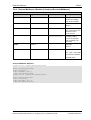
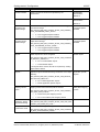
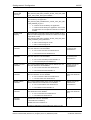
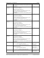
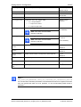
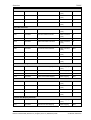
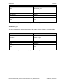
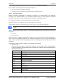
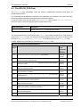
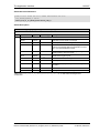
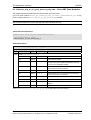
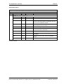
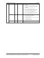
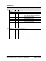
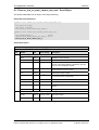
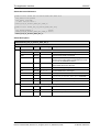
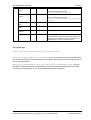
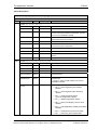
1.2 List of Revisions
Rev
Date
Name
Revisions
1
2007-11-09
RG/SB
Created
2
2008-03-04
RG
Added overview section. Changes in sect. 4.2.
Review of technical data section.
Firmware/ stack version 0.96.14.
3
2008-05-30
RG/ET/HH
Added 3 warmstart parameters.
Firmware/ stack version 2.0.3
Reference to netX Dual-Port Memory Interface Manual Revision 5.
Chapter Configuration Parameters restructured
4
2008-06-27
RG/SB
Additional explanations
5
2008-12-08
RG
Firmware/ stack version V2.1.2.
Reference to netX Dual-Port Memory Interface Manual Revision 7.
Warmstart -> Set Configuration
Registration/unregistration packet marked as obsolete.
Changed some error numbers to global error numbers
Added section on task structure.
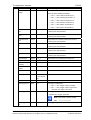
6
2009-04-16
RG/SB
Firmware/ stack version V2.1.9.
Table 212 changed
Description of EPLCN_PCK_REGISTER_REQ changed
7
2010-07-02
RG
Firmware/ stack version V2.1.18
Reference to netX Dual-Port Memory Interface Manual Revision 9.
Some small corrections and additions
8
2010-12-15
RG
Firmware/ stack version V2.1.23
Reference to netX Dual-Port Memory Interface Manual Revision 9.
Small error corrections
9
2012-02-14
RG
Firmware/ stack version V2.1.31
Reference to netX Dual-Port Memory Interface Manual Revision 9.
Renamed host ready bit to bus on/off bit.
Added new section 4.2.1“Timing of PRes Data Exchange”
10
2012-07-31
RG
Firmware/ stack version V2.1.33
Reference to netX Dual-Port Memory Interface Manual Revision 12
Names of stack configuration flags now mentioned in description for easy
finding
Added description of 3 stack configuration flags
11
2013-05-28
RG
Firmware/ stack version V2.1.40
Reference to netX Dual-Port Memory Interface Manual Revision 12
Added description of two new stack configuration flags.
Added description of new configuration parameter ulDeviceType
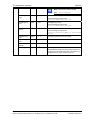
12
2013-09-23
RG/SB
Firmware/ stack version V2.1.41
Reference to netX Dual-Port Memory Interface Manual Revision 12
Unit of ulCycleLength changed to µs
Table 1: List of Revisions
Ethernet POWERLINK Controlled Node |
DOC071104API12EN | Revision 12 | English | 2013-10 | Released | Public
© Hilscher, 2006-2013
Introduction
7/297
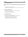
1.3 Functional Overview
This stack has been written to meet the requirements outlined in the EPL specification. The user of
this stack is provided with a fully functional general-purpose Software package with the following main
features:
Implementation of the EPL- state machine
Implementation of the CANopen-style object dictionary according to the EPL specification
1.4 System Requirements
This software package has the following environmental system requirements:
netX-Chip as CPU hardware platform
Operating system for task scheduling required
1.5 Intended Audience
This manual is suitable for software developers with the following background:
Knowledge of the programming language C
Knowledge of the use of the real time operating system rcX
Knowledge of the Hilscher Task Layer Reference Model
Knowledge of the Ethernet Powerlink V 2.0 Specification
Ethernet POWERLINK Controlled Node |
DOC071104API12EN | Revision 12 | English | 2013-10 | Released | Public
© Hilscher, 2006-2013
Introduction
8/297
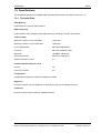
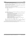
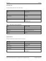
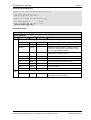
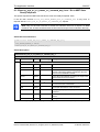
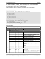
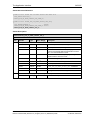
1.6 Specifications
The data below applies to the POWERLINK Controlled Node firmware and stack version V2.1.x.x.
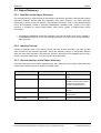
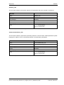
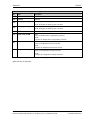
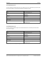
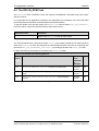
1.6.1 Technical Data
State Machine
Implementation of the EPL-state machine
Object dictionary
Implementation of the CANopen-style object dictionary according to the EPL specification
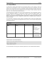
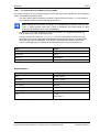
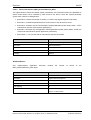
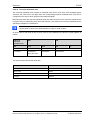
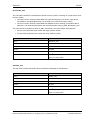
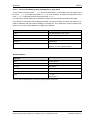
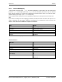
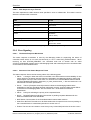
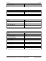
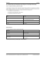
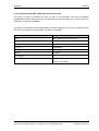
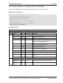
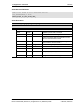
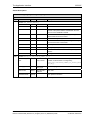
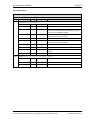
Technical Data
Maximum number of cyclic input data
1490 bytes
Maximum number of cyclic output data
1490 bytes
Acyclic data transfer
SDO Upload/Download
Functions:
SDO over ASND and UDP
Baud rate
100 MBit/s, half-duplex
Data transport layer
Ethernet II, IEEE 802.3
Ethernet Powerlink version
V2
Firmware/stack available for netX
netX 50
yes
netX 100, netX 500
yes
Configuration
Configuration by packet to transfer warmstart parameters
Diagnostic
Firmware supports common diagnostic in the dual-port-memory for loadable firmware
Limitations
No slave to slave communication (Loadable firmware)
Ethernet POWERLINK Controlled Node |
DOC071104API12EN | Revision 12 | English | 2013-10 | Released | Public
© Hilscher, 2006-2013
Introduction
9/297
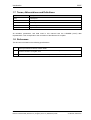
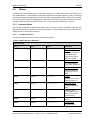
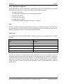
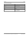
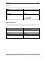
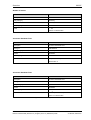
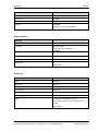
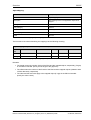
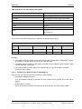
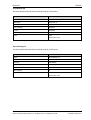
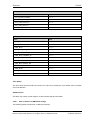
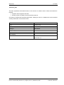
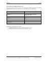
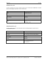
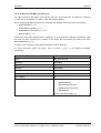
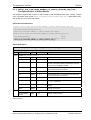
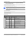
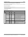
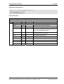
1.7 Terms, Abbreviations and Definitions
Term
Description
PReq
Poll Request
PRes
Poll Response
SoC
Start of Cyclic
SoA
Start of Asynchronous
ASnd
Asynchronous Send
Table 2: Terms, Abbreviations and Definitions
All variables, parameters, and data used in this manual have the LSB/MSB (“Intel”) data
representation. This corresponds to the convention of the Microsoft C Compiler.
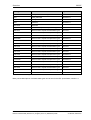
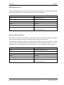
1.8 References
This document is based on the following specifications:
1
Task Layer Reference Manual, Hilscher GmbH
2
Hilscher Gesellschaft für Systemautomation mbH: Dual-Port Memory Interface Manual - netX based
products. Revision 12, English, 2012
3
Ethernet Powerlink V. 2.0 Communication Profile Specification; EPSG; 2004 (DS 1.0.0)
Table 3: References
Ethernet POWERLINK Controlled Node |
DOC071104API12EN | Revision 12 | English | 2013-10 | Released | Public
© Hilscher, 2006-2013
Introduction
1.9
1.9.1
©
10/297
Legal Notes
Copyright
2006-2013 Hilscher Gesellschaft für Systemautomation mbH
All rights reserved.
The images, photographs and texts in the accompanying material (user manual, accompanying texts,
documentation, etc.) are protected by German and international copyright law as well as international
trade and protection provisions. You are not authorized to duplicate these in whole or in part using
technical or mechanical methods (printing, photocopying or other methods), to manipulate or transfer
using electronic systems without prior written consent. You are not permitted to make changes to
copyright notices, markings, trademarks or ownership declarations. The included diagrams do not take
the patent situation into account. The company names and product descriptions included in this
document may be trademarks or brands of the respective owners and may be trademarked or
patented. Any form of further use requires the explicit consent of the respective rights owner.
1.9.2
Important Notes
The user manual, accompanying texts and the documentation were created for the use of the products
by qualified experts, however, errors cannot be ruled out. For this reason, no guarantee can be made
and neither juristic responsibility for erroneous information nor any liability can be assumed.
Descriptions, accompanying texts and documentation included in the user manual do not present a
guarantee nor any information about proper use as stipulated in the contract or a warranted feature. It
cannot be ruled out that the user manual, the accompanying texts and the documentation do not
correspond exactly to the described features, standards or other data of the delivered product. No
warranty or guarantee regarding the correctness or accuracy of the information is assumed.
We reserve the right to change our products and their specification as well as related user manuals,
accompanying texts and documentation at all times and without advance notice, without obligation to
report the change. Changes will be included in future manuals and do not constitute any obligations.
There is no entitlement to revisions of delivered documents. The manual delivered with the product
applies.
Hilscher Gesellschaft für Systemautomation mbH is not liable under any circumstances for direct,
indirect, incidental or follow-on damage or loss of earnings resulting from the use of the information
contained in this publication.
1.9.3
Exclusion of Liability
The software was produced and tested with utmost care by Hilscher Gesellschaft für
Systemautomation mbH and is made available as is. No warranty can be assumed for the
performance and flawlessness of the software for all usage conditions and cases and for the results
produced when utilized by the user. Liability for any damages that may result from the use of the
hardware or software or related documents, is limited to cases of intent or grossly negligent violation
of significant contractual obligations. Indemnity claims for the violation of significant contractual
obligations are limited to damages that are foreseeable and typical for this type of contract.
It is strictly prohibited to use the software in the following areas:
Ethernet POWERLINK Controlled Node |
DOC071104API12EN | Revision 12 | English | 2013-10 | Released | Public
© Hilscher, 2006-2013
Introduction
11/297
for military purposes or in weapon systems;
for the design, construction, maintenance or operation of nuclear facilities;
in air traffic control systems, air traffic or air traffic communication systems;
in life support systems;
in systems in which failures in the software could lead to personal injury or injuries leading to death.
We inform you that the software was not developed for use in dangerous environments requiring failproof control mechanisms. Use of the software in such an environment occurs at your own risk. No
liability is assumed for damages or losses due to unauthorized use.
1.9.4
Export
The delivered product (including the technical data) is subject to export or import laws as well as the
associated regulations of different counters, in particular those of Germany and the USA. The software
may not be exported to countries where this is prohibited by the United States Export Administration
Act and its additional provisions. You are obligated to comply with the regulations at your personal
responsibility. We wish to inform you that you may require permission from state authorities to export,
re-export or import the product.
Ethernet POWERLINK Controlled Node |
DOC071104API12EN | Revision 12 | English | 2013-10 | Released | Public
© Hilscher, 2006-2013
Fundamentals
12/297
2 Fundamentals
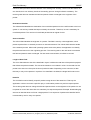
2.1 General Access Mechanisms on netX Systems
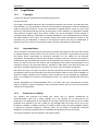
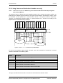
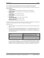
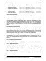
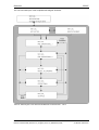
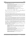
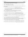
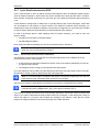
This chapter explains the possible ways to access a Protocol Stack running on a netX system :
1. By accessing the Dual Port Memory Interface directly or via a driver.
2. By accessing the Dual Port Memory Interface via a shared memory.
3. By interfacing with the Stack Task of the Protocol Stack.
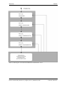
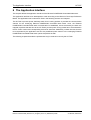
The picture below visualizes these three ways:
1
2
(Extended) Status Block
Send Mailbox
Reveive Mailbox
Output Data Image
Input Data Image
AP Task
3
Fieldbus Task(s)
Network Abstraction Layer
Network
Figure 1 - The three different Ways to access a Protocol Stack running on a netX System
This chapter explains how to program the stack (alternative 3) correctly while the next chapter
describes accessing the protocol stack via the dual-port memory interface according to alternative 1
(and 2, if the user application is executed on the netX chip in the context of the rcX operating system
and uses the shared DPM). Finally, chapter 6 titled “The Application Interface” describes the entire
interface to the protocol stack in detail.
Depending on you choose the stack-oriented approach or the Dual Port Memory-based approach, you
will need either the information given in this chapter or those of the next chapter to be able to work
with the set of functions described in chapter 5. All of those functions use the four parameters
ulDest, ulSrc, ulDestId and ulSrcId. This chapter and the next one inform about how to
work with these important parameters.
Ethernet POWERLINK Controlled Node |
DOC071104API12EN | Revision 12 | English | 2013-10 | Released | Public
© Hilscher, 2006-2013
Fundamentals
13/297
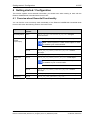
2.2 Accessing the Protocol Stack by Programming the AP Task’s
Queue
In general, programming the AP task or the stack has to be performed according to the rules
explained in the Hilscher Task Layer Reference Manual. There you can also find more information
about the variables discussed in the following.
2.2.1 Getting the Receiver Task Handle of the Process Queue
To get the handle of the process queue of the EPLCN_PCK-Task or the EPLCN_DPM-Task the Macro
TLR_QUE_IDENTIFY() needs to be used. It is described in detail within section 10.1.9.3 of the
Hilscher Task Layer Reference Model Manual. This macro delivers a pointer to the handle of the
intended queue to be accessed (which is returned within the third parameter, phQue), if you provide it
with the name of the queue (and an instance of your own task). The correct ASCII-queue names for
accessing the EPLCN_PCK-Task or the EPLCN_DPM-Task, which you have to use as current value for
the first parameter (pszIdn), is
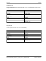
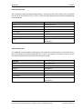
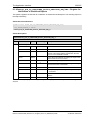
ASCII Queue name
Description
"QUE_EPLCN_PCK”
Name of the EPLCN_PCK-Task process queue
"QUE_EPLCN_DPM”
Name of the EPLCN_DPM-Task process queue
Table 4: Names of Queues in EtherNet/IP Firmware
The returned handle has to be used as value ulDest in all initiator packets the AP-Task intends to
send to the EPLCN_PCK-Task . This handle is the same handle that has to be used in conjunction with
the macros like TLR_QUE_SENDPACKET_FIFO/LIFO() for sending a packet to the respective task.
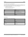
2.2.2 Meaning of Source- and Destination-related Parameters
The meaning of the source- and destination-related parameters is explained in the following table:
Variable
Meaning
ulDest
Application mailbox used for confirmation
ulSrc
Queue handle returned by TLR_QUE_IDENTIFY() as described above.
ulSrcId
Used for addressing at a lower level
Table 5: Meaning of Source- and Destination-related Parameters.
For more information about programming the AP task’s stack queue, please refer to the Hilscher Task
Layer Reference Model Manual. Especially the following sections might be of interest in this context:
1. Chapter 7 “Queue-Packets”
2. Section 10.1.9 “Queuing Mechanism”
Ethernet POWERLINK Controlled Node |
DOC071104API12EN | Revision 12 | English | 2013-10 | Released | Public
© Hilscher, 2006-2013
Fundamentals
14/297
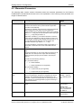
2.3 Accessing the Protocol Stack via the Dual Port Memory
Interface
This chapter defines the application interface of the Ethernet Powerlink Controlled Node Stack.
2.3.1 Communication via Mailboxes
The mailbox of each communication channel has two areas that are used for non-cyclic message
transfer to and from the netX.
Send Mailbox
Packet transfer from host system to netX firmware
Receive Mailbox
Packet transfer from netX firmware to host system
For more details about acyclic data transfer via mailboxes, see section 3.2. Acyclic Data (Mailboxes) in
this context, is described in detail in section 3.2.1 “General Structure of Messages or Packets for NonCyclic Data Exchange” while the possible codes that may appear are listed in section 3.2.2. “Status &
Error Codes”.
However, this section concentrates on correct addressing the mailboxes.
Ethernet POWERLINK Controlled Node |
DOC071104API12EN | Revision 12 | English | 2013-10 | Released | Public
© Hilscher, 2006-2013
Fundamentals
15/297
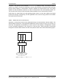
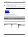
2.3.2 Using Source and Destination Variables correctly
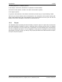
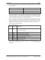
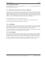
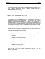
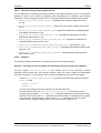
2.3.2.1
How to use ulDest for Addressing rcX and the netX Protocol Stack by the System
and Channel Mailbox
System
Mailbox
Channel 0
Mainbox
ulDest = 0x02
ulDest = 0x01
ulDest = 0x00
ulDest = 0x20
ulDest = 0x02
ulDest = 0x01
ulDest = 0x00
ulDest = 0x20
ulDest = 0x02
ulDest = 0x01
ulDest = 0x00
ulDest = 0x20
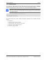
The preferred way to address the netX operating system rcX is through the system mailbox; the
preferred way to address a protocol stack is through its channel mailbox. All mailboxes, however, have
a mechanism to route packets to a communication channel or the system channel, respectively.
Therefore, the destination identifier ulDest in a packet header has to be filled in according to the
targeted receiver. See the following example:
Channel 1
Mailbox
netX OS
rcX
AP Task 1
AP Task 2
Figure 2 - Use of ulDest in Channel and System Mailbox
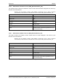
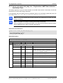
For use in the destination queue handle, the tasks have been assigned to hexadecimal numerical
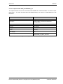
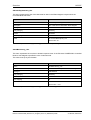
values as described in the following table:
ulDest
Description
0x00000000
Packet is passed to the netX operating system rcX
0x00000001
Packet is passed to communication channel 0
0x00000002
Packet is passed to communication channel 1
0x00000003
Packet is passed to communication channel 2
0x00000004
Packet is passed to communication channel 3
0x00000020
Packet is passed to communication channel of the mailbox
else
Reserved, do not use
Table 6: Meaning of Destination-Parameter ulDest.Parameters.
The figure and the table above both show the use of the destination identifier ulDest.
Ethernet POWERLINK Controlled Node |
DOC071104API12EN | Revision 12 | English | 2013-10 | Released | Public
© Hilscher, 2006-2013
Fundamentals
16/297
A remark on the special channel identifier 0x00000020 (= Channel Token). The Channel Token is
valid for any mailbox. That way the application uses the same identifier for all packets without actually
knowing which mailbox or communication channel is applied. The packet stays 'local'. The system
mailbox is a little bit different, because it is used to communicate to the netX operating system rcX.
The rcX has its own range of valid commands codes and differs from a communication channel.
Unless there is a reply packet, the netX operating system returns it to the same mailbox the request
packet went through. Consequently, the host application has to return its reply packet to the mailbox
the request was received from.
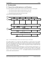
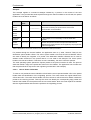
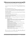
2.3.2.2
How to use ulSrc and ulSrcId
Generally, a netX protocol stack can be addressed through its communication channel mailbox. The
example below shows how a host application addresses a protocol stack running in the context of a
netX chip. The application is identified by a number (#444 in this example). The application consists
of three processes identified by the numbers #11, #22 and #33. These processes communicate
through the channel mailbox with the AP task of the protocol stack. Have a look at the following figure:
Process #33
Process #22
Process #11
Application #444
Channel
Mainbox
netX Protocol stack
AP Task 1
Figure 3 - Using ulSrc and ulSrcId
Ethernet POWERLINK Controlled Node |
DOC071104API12EN | Revision 12 | English | 2013-10 | Released | Public
© Hilscher, 2006-2013
Fundamentals
17/297
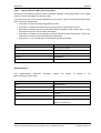
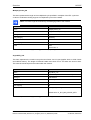
Example:
This example applies to command messages initiated by a process in the context of the host
application. If the process #22 sends a packet through the channel mailbox to the AP task, the packet
header has to be filled in as follows:
Object
Variable
Name
Numeric Value
Explanation
Destination
Queue
Handle
ulDest
= 32
This value needs always to be set to 0x00000020 (the channel
token) when accessing the protocol stack via the local
communication channel mailbox.
Source
Queue
Handle
ulSrc
= 444
Denotes the host application (#444).
Destination
Identifier
ulDestId
= 0
In this example, it is not necessary to use the destination
identifier.
Source
Identifier
ulSrcId
= 22
Denotes the process number of the process within the host
application and needs therefore to be supplied by the programmer
of the host application.
(0x00000020)
Table 7 Example for correct Use of Source- and Destination-related parameters.:
For packets through the channel mailbox, the application uses 32 (= 0x20, Channel Token) for the
destination queue handler ulDest. The source queue handler ulSrc and the source identifier ulSrcId
are used to identify the originator of a packet. The destination identifier ulDestId can be used to
address certain resources in the protocol stack. It is not used in this example. The source queue
handler ulSrc has to be filled in. Therefore, its use is mandatory; the use of ulSrcId is optional.
The netX operating system passes the request packet to the protocol stack's AP task. The protocol
stack then builds a reply to the packet and returns it to the mailbox. The application has to make sure
that the packet finds its way back to the originator (process #22 in the example).
2.3.2.3
How to Route rcX Packets
To route an rcX packet the source identifier ulSrcId and the source queues handler ulSrc in the packet
header hold the identification of the originating process. The router saves the original handle from
ulSrcId and ulSrc. The router uses a handle of its own choices for ulSrcId and ulSrc before it sends the
packet to the receiving process. That way the router can identify the corresponding reply packet and
matches the handle from that packet with the one stored earlier. Now the router replaces its handles
with the original handles and returns the packet to the originating process.
Ethernet POWERLINK Controlled Node |
DOC071104API12EN | Revision 12 | English | 2013-10 | Released | Public
© Hilscher, 2006-2013
Fundamentals
18/297
2.3.3 Obtaining useful Information about the Communication Channel
A communication channel represents a part of the Dual Port Memory and usually consists of the
following elements:
Output Data Image
is used to transfer cyclic process data to the network (normal or high-priority)
Input Data Image
is used to transfer cyclic process data from the network (normal or high-priority)
Send Mailbox
is used to transfer non-cyclic data to the netX
Receive Mailbox
is used to transfer non-cyclic data from the netX
Control Block
allows the host system to control certain channel functions
Common Status Block
holds information common to all protocol stacks
Extended Status Block
holds protocol specific network status information
This section describes a procedure how to obtain useful information for accessing the communication
channel(s) of your netX device and to check if it is ready for correct operation.
Proceed as follows:
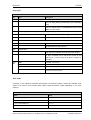
1) Start with reading the channel information block within the system channel (usually starting at
address 0x0030).
2) Then you should check the hardware assembly options of your netX device. They are located
within the system information block following offset 0x0010 and stored as data type UINT16.
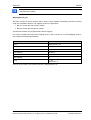
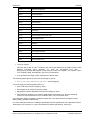
The following table explains the relationship between the offsets and the corresponding xC
Ports of the netX device:
0x0010
Hardware Assembly Options for xC Port[0]
0x0012
Hardware Assembly Options for xC Port[1]
0x0014
Hardware Assembly Options for xC Port[2]
0x0016
Hardware Assembly Options for xC Port[3]
Check each of the hardware assembly options whether its value has been set to
RCX_HW_ASSEMBLY_ETHERNET = 0x0080. If true, this denotes that this xCPort is suitable
for running the Ethernet POWERLINK Controlled Node protocol stack. Otherwise, this port is
designed for another communication protocol. In most cases, xC Port[2] will be used for field
bus systems, while xC Port[0] and xC Port[1] are normally used for Ethernet communication.
Ethernet POWERLINK Controlled Node |
DOC071104API12EN | Revision 12 | English | 2013-10 | Released | Public
© Hilscher, 2006-2013
Fundamentals
19/297
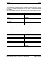
3) You can find information about the corresponding communication channel (0…3) under the
following addresses:
0x0050
Communication Channel 0
0x0060
Communication Channel 1
0x0070
Communication Channel 2
0x0080
Communication Channel 3
In devices which support only one communication system which is usually the case (either a
single field bus system or a single standard for Industrial-Ethernet communication), always
communication channel 0 will be used. In devices supporting more than one communication
system you should also check the other communication channels.
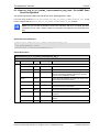
4) There you can find such information as the ID (containing channel number and port number)
of the communication channel, the size and the location of the handshake cells, the overall
number of blocks within the communication channel and the size of the channel in bytes.
Evaluate this information precisely in order to access the communication channel correctly.
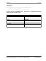
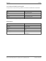
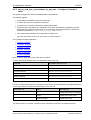
The information is delivered as follows:
Size of Channel in Bytes
Address
Data Type
Description
0x0050
UINT8
Channel Type = COMMUNICATION
(must have the fixed value
define RCX_CHANNEL_TYPE_COMMUNICATION = 0x05)
0x0051
UINT8
ID (Channel Number, Port Number)
0x0052
UINT8
Size / Position Of Handshake Cells
0x0053
UINT8
Total Number Of Blocks Of This Channel
0x0054
UINT32
Size Of Channel In Bytes
0x0058
UINT8[8]
Reserved (set to zero)
These addresses correspond to communication channel 0, for communication channels 1, 2
and 3 you have to add an offset of 0x0010, 0x0020 or 0x0030 to the address values,
respectively.
Ethernet POWERLINK Controlled Node |
DOC071104API12EN | Revision 12 | English | 2013-10 | Released | Public
© Hilscher, 2006-2013
Fundamentals
20/297
2.4 Client/Server Mechanism
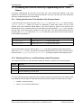
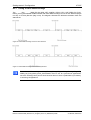
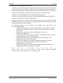
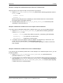
2.4.1 Application as Client
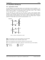
The host application may send request packets to the netX firmware at any time (transition 1 2).
Depending on the protocol stack running on the netX, parallel packets are not permitted (see protocol
specific manual for details). The netX firmware sends a confirmation packet in return, signaling
success or failure (transition 3 4) while processing the request.
The host application has to register with the netX firmware in order to receive indication packets
(transition 5 6). Depending on the protocol stack, this is done either implicitly (if application opens a
TCP/UDP socket) or explicitly. Details on when and how to register for certain events is described in
the protocol specific manual. Depending on the command code of the indication packet, a response
packet to the netX firmware may or may not be required (transition 7 8).
Application
netX
Figure 4: Transition Chart Application as Client
The host application sends request packets to the netX firmware.
The netX firmware sends a confirmation packet in return.
The host application receives indication packets from the netX firmware.
The host application sends response packet to the netX firmware (may not be required).
Request
Confirmation
Indication
Response
Ethernet POWERLINK Controlled Node |
DOC071104API12EN | Revision 12 | English | 2013-10 | Released | Public
© Hilscher, 2006-2013
Fundamentals
21/297
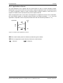
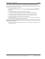
2.4.2 Application as Server
The host application has to register with the netX firmware in order to receive indication packets.
Depending on the protocol stack, this is done either implicit (if application opens a TCP/UDP socket)
or explicit (if application wants to receive unsolicited DPV1 packets). Details on when and how to
register for certain events is described in the protocol specific manual.
When an appropriate event occurs and the host application is registered to receive such a notification,
the netX firmware passes an indication packet through the mailbox (transition 1 2). The host
application is expected to send a response packet back to the netX firmware (transition 3 4).
Application
netX
Figure 5: Transition Chart Application as Server
The netX firmware passes an indication packet through the mailbox.
The host application sends response packet to the netX firmware.
Indication
Response
Ethernet POWERLINK Controlled Node |
DOC071104API12EN | Revision 12 | English | 2013-10 | Released | Public
© Hilscher, 2006-2013
Dual-Port Memory
22/297
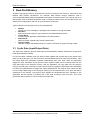
3 Dual-Port Memory
All data in the dual-port memory is structured in blocks. According to their functions, these blocks use
different data transfer mechanisms. For example, data transfer through mailboxes uses a
synchronized handshake mechanism between host system and netX firmware. The same is true for IO
data images, when a buffered handshake mode is configured. Other blocks, like the status block, are
read by the host application and use no synchronization mechanism.
Types of blocks in the dual-port memory are outlined below:
Mailbox
transfer non-cyclic messages or packages with a header for routing information
Data Area
holds the process image for cyclic IO data or user defined data structures
Control Block
is used to signal application related state to the netX firmware
Status Block
holds information regarding the current network state
Change of State
collection of flags, that initiate execution of certain commands or signal a change of state
3.1 Cyclic Data (Input/Output Data)
The input block holds the process data image received from the network whereas the output block
holds data sent to the network.
For the controlled / buffered mode, the protocol stack updates the process data in the internal input
buffer for each valid bus cycle. Each IO block uses handshake bits for access synchronization. Input
and output data block handshake operates independently from each other. When the application
toggles the input handshake bit, the protocol stack copies the data from the internal buffer into the
input data image of the dual-port memory. Now the application can copy data from the dual-port
memory and then give control back to the protocol stack by toggling the appropriate input handshake
bit. When the application/driver toggles the output handshake bit, the protocol stack copies the data
from the output data image of the dual-port memory into the internal buffer. From there the data is
transferred to the network. The protocol stack toggles the handshake bits back, indicating to the
application that the transfer is finished and a new data exchange cycle may start. This mode
guarantees data consistency over both input and output area.
Ethernet POWERLINK Controlled Node |
DOC071104API12EN | Revision 12 | English | 2013-10 | Released | Public
© Hilscher, 2006-2013
Dual-Port Memory
23/297
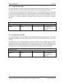
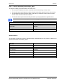
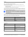
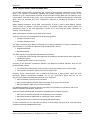
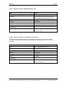
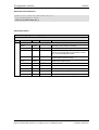
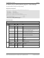
3.1.1 Input Process Data
The input data block is used by fieldbus and industrial Ethernet protocols that utilize a cyclic data
exchange mechanism. The input data image is used to receive cyclic data from the network.
The default size of the input data image is 5760 byte. However, not all available space is actually used
by the protocol stack. Depending on the specific protocol, the area actually available for user data
might be much smaller than 5760 byte. An input data block may or may not be available in the dualport memory. It is always available in the default memory map (see the netX Dual-Port Memory
Manual).
Input Data Image
Offset
Type
Name
Description
0x2680
UINT8
abPd0Input[5760]
Input Data Image
Cyclic Data From The
Network
Table 8: Input Data Image
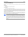
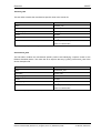
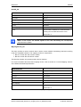
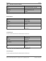
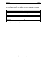
3.1.2 Output Process Data
The output data block is used by fieldbus and industrial Ethernet protocols that utilize a cyclic data
exchange mechanism. The output data Image is used to send cyclic data from the host to the
network.
The default size of the output data image is 5760 byte. However, not all available space is actually
used by the protocol stack. Depending on the specific protocol, the area actually available for user
data might be much smaller than 5760 byte. An output data block may or may not be available in the
dual-port memory. It is always available in the default memory map (see the netX DPM Manual).
Output Data Image
Offset
Type
Name
Description
0x1000
UINT8
abPd0Output[5760]
Output Data Image
Cyclic Data To The
Network
Table 9: Output Data Image
Ethernet POWERLINK Controlled Node |
DOC071104API12EN | Revision 12 | English | 2013-10 | Released | Public
© Hilscher, 2006-2013
Dual-Port Memory
24/297
3.2 Acyclic Data (Mailboxes)
The mailbox of each communication channel has two areas that are used for non-cyclic message
transfer.
Send Mailbox
Packet transfer from host system to firmware
Receive Mailbox
Packet transfer from firmware to host system
The send and receive mailbox areas are used by field bus protocols providing a non-cyclic data
exchange mechanism. Another use of the mailbox system is to allow access to the firmware running
on the netX chip itself for diagnostic and identification purposes. The send mailbox is used to transfer
cyclic data to the network or to the firmware. The receive mailbox is used to transfer cyclic data
from the network or from the firmware.
A send/receive mailbox may or may not be available in the communication channel. It depends on the
function of the firmware whether or not a mailbox is needed. The location of the system mailbox and
the channel mailbox is described in the netX DPM Interface Manual.
Note: Each mailbox can hold one packet at a time. The netX firmware stores packets that
are not retrieved by the host application in a packet queue. This queue has limited space
and may fill up so new packets maybe lost. To avoid these data loss situations, it is
strongly recommended to empty the mailbox frequently, even if packets are not expected
by the host application. Unexpected command packets should be returned to the sender
with an Unknown Command in the status field; unexpected reply messages can be
discarded.
Ethernet POWERLINK Controlled Node |
DOC071104API12EN | Revision 12 | English | 2013-10 | Released | Public
© Hilscher, 2006-2013
Dual-Port Memory
25/297
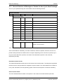
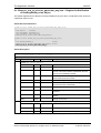
3.2.1 General Structure of Messages or Packets for Non-Cyclic Data Exchange
The non-cyclic packets through the netX mailbox have the following structure:
Structure Information
Area
Variable
Head
Structure Information
Data
Type
Value / Range
Description
ulDest
UINT32
Destination Queue Handle
ulSrc
UINT32
Source Queue Handle
ulDestId
UINT32
Destination Queue Reference
ulSrcId
UINT32
Source Queue Reference
ulLen
UINT32
Packet Data Length (In Bytes)
ulId
UINT32
Packet Identification As Unique Number
ulSta
UINT32
Status / Error Code
ulCmd
UINT32
Command / Response
ulExt
UINT32
Reserved
ulRout
UINT32
Routing Information
Structure Information
…
…
User Data
Specific To The Command
Table 10: General Structure of Packets for non-cyclic Data Exchange.
Some of the fields are mandatory; some are conditional; others are optional. However, the size of a
packet is always at least 10 double-words or 40 bytes. Depending on the command, a packet may or
may not have a data field. If present, the content of the data field is specific to the command,
respectively the reply.
Destination Queue Handle
The ulDest field identifies a task queue in the context of the netX firmware. The task queue represents
the final receiver of the packet and is assigned to a protocol stack. The ulDest field has to be filled out
in any case. Otherwise, the netX operating system cannot route the packet. This field is mandatory.
Source Queue Handle
The ulSrc field identifies the sender of the packet. In the context of the netX firmware (inter-task
Ethernet POWERLINK Controlled Node |
DOC071104API12EN | Revision 12 | English | 2013-10 | Released | Public
© Hilscher, 2006-2013
Dual-Port Memory
26/297
communication) this field holds the identifier of the sending task. Usually, a driver uses this field for its
own handle, but it can hold any handle of the sending process. Using this field is mandatory. The
receiving task does not evaluate this field and passes it back unchanged to the originator of the
packet.
Destination Identifier
The ulDestId field identifies the destination of an unsolicited packet from the netX firmware to the host
system. It can hold any handle that helps to identify the receiver. Therefore, its use is mandatory for
unsolicited packets. The receiver of unsolicited packets has to register for this.
Source Identifier
The ulSrcId field identifies the originator of a packet. This field is used by a host application, which
passes a packet from an external process to an internal netX task. The ulSrcId field holds the handle
of the external process. When netX operating system returns the packet, the application can identify
the packet and returns it to the originating process. The receiving task on the netX does not evaluate
this field and passes it back unchanged. For inter-task communication, this field is not used.
Length of Data Field
The ulLen field holds the size of the data field in bytes. It defines the total size of the packet’s payload
that follows the packet’s header. The size of the header is not included in ulLen. So the total size of a
packet is the size from ulLen plus the size of packet’s header. Depending on the command, a data
field may or may not be present in a packet. If no data field is included, the length field is set to zero.
Identifier
The ulId field is used to identify a specific packet among others of the same kind. That way the
application or driver can match a specific reply or confirmation packet to a previous request packet.
The receiving task does not change this field and passes it back to the originator of the packet. Its use
is optional in most of the cases. But it is mandatory for sequenced packets. Example: Downloading big
amounts of data that does not fit into a single packet. For a sequence of packets the identifier field is
incremented by one for every new packet.
Ethernet POWERLINK Controlled Node |
DOC071104API12EN | Revision 12 | English | 2013-10 | Released | Public
© Hilscher, 2006-2013
Dual-Port Memory
27/297
Status / Error Code
The ulState field is used in response or confirmation packets. It informs the originator of the packet
about success or failure of the execution of the command. The field may be also used to hold status
information in a request packet.
Command / Response
The ulCmd field holds the command code or the response code, respectively. The command/response
is specific to the receiving task. If a task is not able to execute certain commands, it will return the
packet with an error indication. A command is always even (the least significant bit is zero). In the
response packet, the command code is incremented by one indicating a confirmation to the request
packet.
Extension
The extension field ulExt is used for controlling packets that are sent in a sequenced manner. The
extension field indicates the first, last or a packet of a sequence. If sequencing is not required, the
extension field is not used and set to zero.
Routing Information
The ulRout field is used internally by the netX firmware only. It has no meaning to a driver type
application and therefore set to zero.
User Data Field
This field contains data related to the command specified in ulCmd field. Depending on the command,
a packet may or may not have a data field. The length of the data field is given in the ulLen field.
Ethernet POWERLINK Controlled Node |
DOC071104API12EN | Revision 12 | English | 2013-10 | Released | Public
© Hilscher, 2006-2013
Dual-Port Memory
28/297
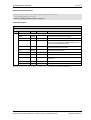
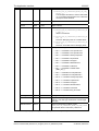
3.2.2 Status & Error Codes
The following status and error codes can be returned in ulState: List of codes see manual named
netX Dual-Port Memory Interface.
3.2.3 Differences between System and Channel Mailboxes
The mailbox system on netX provides a non-cyclic data transfer channel for field bus and industrial
Ethernet protocols. Another use of the mailbox is allowing access to the firmware running on the netX
chip itself for diagnostic purposes. There is always a send and a receive mailbox. Send and receive
mailboxes utilize handshake bits to synchronize these data or diagnostic packages through the
mailbox. There is a pair of handshake bits for both the send and receive mailbox.
The netX operating system rcX only uses the system mailbox.
The system mailbox, however, has a mechanism to route packets to a communication channel.
A channel mailbox passes packets to its own protocol stack only.
3.2.4 Send Mailbox
The send mailbox area is used by protocols utilizing a non-cyclic data exchange mechanism. Another
use of the mailbox system is to provide access to the firmware running on the netX chip itself. The
send mailbox is used to transfer non-cyclic data to the network or to the protocol stack.
The size is 1596 bytes for the send mailbox in the default memory layout. The mailbox is accompanied
by counters that hold the number of packages that can be accepted.
3.2.5 Receive Mailbox
The receive mailbox area is used by protocols utilizing a non-cyclic data exchange mechanism.
Another use of the mailbox system is to provide access to the firmware running on the netX chip itself.
The receive mailbox is used to transfer non-cyclic data from the network or from the protocol stack.
The size is 1596 bytes for the receive mailbox in the default memory layout. The mailbox is
accompanied by counters that hold the number of waiting packages (for the receive mailbox).
Ethernet POWERLINK Controlled Node |
DOC071104API12EN | Revision 12 | English | 2013-10 | Released | Public
© Hilscher, 2006-2013
Dual-Port Memory
29/297
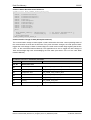
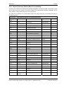
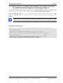
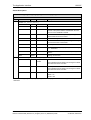
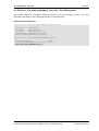
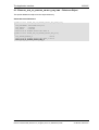
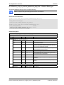
3.2.6 Channel Mailboxes (Details of Send and Receive Mailboxes)
Master Status
Offset
Type
Name
Description
0x0200
UINT16
usPackagesAccepted
Packages Accepted
Number of Packages
that can be Accepted
0x0202
UINT16
usReserved
Reserved
Set to 0
0x0204
UINT8
abSendMbx[1596]
Send Mailbox
Non Cyclic Data To The
Network or to the
Protocol Stack
0x0840
UINT16
usWaitingPackages
Packages waiting
Counter of packages
that are waiting to be
processed
0x0842
UINT16
usReserved
Reserved
Set to 0
0x0844
UINT8
abRecvMbx[1596]
Receive Mailbox
Non Cyclic Data from
the network or from the
protocol stack
Table 11: Channel Mailboxes.
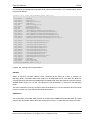
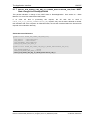
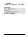
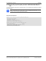
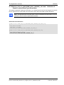
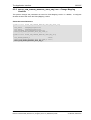
Channel Mailboxes Structure
typedef struct tagNETX_SEND_MAILBOX_BLOCK
{
UINT16 usPackagesAccepted;
UINT16 usReserved;
UINT8 abSendMbx[ 1596 ];
} NETX_SEND_MAILBOX_BLOCK;
typedef struct tagNETX_RECV_MAILBOX_BLOCK
{
UINT16 usWaitingPackages;
UINT16 usReserved;
UINT8 abRecvMbx[ 1596 ];
} NETX_RECV_MAILBOX_BLOCK;
Ethernet POWERLINK Controlled Node |
DOC071104API12EN | Revision 12 | English | 2013-10 | Released | Public
© Hilscher, 2006-2013
Dual-Port Memory
3.3
30/297
Status
A status block is present within the communication channel. It contains information about network and
task related issues. In some respects, status and control block are used together in order to exchange
information between host application and netX firmware. The application reads a status block whereas
the control block is written by the application. Both status and control block have registers that use the
Change of State mechanism (see also section 2.2.1 of the netX Dual-Port-Memory manual).
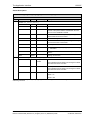
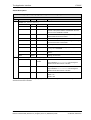
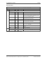
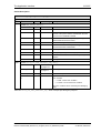
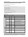
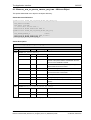
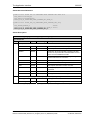
3.3.1 Common Status
The Common Status Block contains information that is the same for all communication channels. The
start offset of this block depends on the size and location of the preceding blocks. The status block is
always present in the dual-port memory.
3.3.1.1
All Implementations
The structure outlined below is common to all protocol stacks.
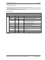
Common Status Structure Definition
Common Status
Offset
Type
Name
Description
0x0010
UINT32
ulCommunicationCOS
Communication Change
of State
READY, RUN, RESET
REQUIRED, NEW,
CONFIG AVAILABLE,
CONFIG LOCKED
0x0014
UINT32
ulCommunicationState
Communication State
NOT CONFIGURED,
STOP, IDLE, OPERATE
0x0018
UINT32
ulCommunicationError
Communication Error
Unique Error Number
According to Protocol
Stack
0x001C
UINT16
usVersion
Version
Version Number of this
Diagnosis Structure
0x001E
UINT16
usWatchdogTime
Watchdog Timeout
Configured Watchdog
Time
0x0020
UINT16
usHandshakeMode
0x0022
UINT16
usReserved
Reserved
Set to 0
0x0024
UINT32
ulHostWatchdog
Host Watchdog
Handshake Mode
Process Data Transfer
Mode (see netX DPM
Interfce Manual)
Joint Supervision
Ethernet POWERLINK Controlled Node |
DOC071104API12EN | Revision 12 | English | 2013-10 | Released | Public
© Hilscher, 2006-2013
Dual-Port Memory
31/297
Mechanism
Protocol Stack Writes,
Host System Reads
0x0028
UINT32
ulErrorCount
Error Count
Total Number of Detected
Error Since Power-Up or
Reset
0x002C
UINT32
ulErrorLoglnd
Error Log Indicator
Total Number Of Entries
In The Error Log
Structure (not supported
yet)
0x0030
UINT32
ulReserved[2]
Reserved
Set to 0
Table 12: Common Status Structure Definition
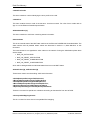
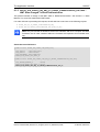
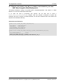
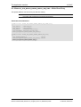
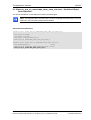
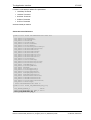
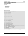
Common Status Block Structure Reference
typedef struct NETX_COMMON_STATUS_BLOCK_Ttag
{
UINT32 ulCommunicationCOS;
UINT32 ulCommunicationState;
UINT32 ulCommunicationError;
UINT16 usVersion;
UINT16 usWatchdogTime;
UINT16 ausReserved[2];
UINT32 ulHostWatchdog;
UINT32 ulErrorCount;
UINT32 ulErrorLogInd;
UINT32 ulReserved[2];
union
{
NETX_MASTER_STATUS_T tMasterStatus;
/* for master implementation */
UINT32
aulReserved[6];
/* otherwise reserved
*/
} unStackDepended;
} NETX_COMMON_STATUS_BLOCK_T;
Ethernet POWERLINK Controlled Node |
DOC071104API12EN | Revision 12 | English | 2013-10 | Released | Public
© Hilscher, 2006-2013
Dual-Port Memory
32/297
Common Status Block Structure Reference
typedef struct NETX_COMMON_STATUS_BLOCK_Ttag
{
UINT32 ulCommunicationCOS;
UINT32 ulCommunicationState;
UINT32 ulCommunicationError;
UINT16 usVersion;
UINT16 usWatchdogTime;
UINT16 ausReserved[2];
UINT32 ulHostWatchdog;
UINT32 ulErrorCount;
UINT32 ulErrorLogInd;
UINT32 ulReserved[2];
union
{
NETX_MASTER_STATUS_T tMasterStatus;
/* for master implementation */
UINT32
aulReserved[6];
/* otherwise reserved
*/
} unStackDepended;
} NETX_COMMON_STATUS_BLOCK_T;
Communication Change of State (All Implementations)
The communication change of state register contains information about the current operating status of
the communication channel and its firmware. Every time the status changes, the netX protocol stack
toggles the netX Change of State Command flag in the netX communication flags register (see section
3.2.2.1 of the netX DPM Interface Manual). The application then has to toggle the netX Change of
State Acknowledge flag back acknowledging the new state (see section 3.2.2.2 of the netX DPM
Interface Manual).
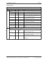
ulCommunicationCOS - netX writes, Host reads
Bit
Short name
Name
D31..D7
unused, set to zero
D6
Restart Required Enable
RCX_COMM_COS_RESTART_REQUIRED_ENABLE
D5
Restart Required
RCX_COMM_COS_RESTART_REQUIRED
D4
Configuration New
RCX_COMM_COS_CONFIG_NEW
D3
Configuration Locked
RCX_COMM_COS_CONFIG_LOCKED
D2
Bus On
RCX_COMM_COS_BUS_ON
D1
Running
RCX_COMM_COS_RUN
D0
Ready
RCX_COMM_COS_READY
Table 13: Communication State of Change
Ethernet POWERLINK Controlled Node |
DOC071104API12EN | Revision 12 | English | 2013-10 | Released | Public
© Hilscher, 2006-2013
Dual-Port Memory
33/297
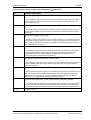
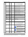
Communication Change of State Flags (netX System Application)
Bit
0
Definition / Description
Ready (RCX_COMM_COS_READY)
0-…
1 - The Ready flag is set as soon as the protocol stack is started properly. Then the protocol
stack is awaiting a configuration. As soon as the protocol stack is configured properly, the
Running flag is set, too.
1
Running (RCX_COMM_COS_RUN)
0-…
1 -The Running flag is set when the protocol stack has been configured properly. Then the
protocol stack is awaiting a network connection. Now both the Ready flag and the Running
flag are set.
2
Bus On (RCX_COMM_COS_BUS_ON)
0-…
1 -The Bus On flag is set to indicate to the host system whether or not the protocol stack has
the permission to open network connections. If set, the protocol stack has the permission to
communicate on the network; if cleared, the permission was denied and the protocol stack
will not open network connections.
3
Configuration Locked (RCX_COMM_COS_CONFIG_LOCKED)
0-…
1 -The Configuration Locked flag is set, if the communication channel firmware has locked
the configuration database against being overwritten. Re-initializing the channel is not
allowed in this state. To unlock the database, the application has to clear the Lock
Configuration flag in the control block (see page 40).
4
Configuration New (RCX_COMM_COS_CONFIG_NEW)
0-…
1 -The Configuration New flag is set by the protocol stack to indicate that a new configuration
became available, which has not been activated. This flag may be set together with the
Restart Required flag.
5
Restart Required (RCX_COMM_COS_RESTART_REQUIRED)
0-…
1 -The Restart Required flag is set when the channel firmware requests to be restarted. This
flag is used together with the Restart Required Enable flag below. Restarting the channel
firmware may become necessary, if a new configuration was downloaded from the host
application or if a configuration upload via the network took place.
6
Restart Required Enable (RCX_COMM_COS_RESTART_REQUIRED_ENABLE)
0-…
1 - The Restart Required Enable flag is used together with the Restart Required flag above. If
set, this flag enables the execution of the Restart Required command in the netX firmware
(for details on the Enable mechanism see section 2.3.2 of the netX DPM Interface Manual)).
7 … 31
Reserved, set to 0
Table 14: Meaning of Communication Change of State Flags
Ethernet POWERLINK Controlled Node |
DOC071104API12EN | Revision 12 | English | 2013-10 | Released | Public
© Hilscher, 2006-2013
Dual-Port Memory
34/297
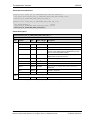
Communication State (All Implementations)
The communication state field contains information regarding the current network status of the
communication channel. Depending on the implementation, all or a subset of the definitions below is
supported.
UNKNOWN
#define RCX_COMM_STATE_UNKNOWN
NOT_CONFIGURED
#define RCX_COMM_STATE_NOT_CONFIGURED 0x00000001
STOP
#define RCX_COMM_STATE_STOP
0x00000002
IDLE
#define RCX_COMM_STATE_IDLE
0x00000003
OPERATE
#define RCX_COMM_STATE_OPERATE
0x00000004
0x00000000
Communication Channel Error (All Implementations)
This field holds the current error code of the communication channel. If the cause of error is resolved,
the communication error field is set to zero (= RCX_SYS_SUCCESS) again. Not all of the error codes
are supported in every implementation. Protocol stacks may use a subset of the error codes below.
SUCCESS
#define RCX_SYS_SUCCESS
0x00000000
#define RCX_E_WATCHDOG_TIMEOUT
0xC000000C
Runtime Failures
WATCHDOG TIMEOUT
Initialization Failures
(General) INITIALIZATION FAULT
#define RCX_E_INIT_FAULT
DATABASE ACCESS FAILED
0xC0000100
#define RCX_E_DATABASE_ACCESS_FAILED
0xC0000101
Configuration Failures
NOT CONFIGURED
(General) CONFIGURATION FAULT
#define RCX_E_CONFIGURATION_FAULT
INCONSISTENT DATA SET
#define RCX_E_NOT_CONFIGURED
0xC0000119
0xC0000120
#define RCX_E_INCONSISTENT_DATA_SET
0xC0000121
DATA SET MISMATCH
#define RCX_E_DATA_SET_MISMATCH
INSUFFICIENT LICENSE
#define RCX_E_INSUFFICIENT_LICENSE
0xC0000122
0xC0000123
PARAMETER ERROR
INVALID NETWORK ADDRESS #define RCX_E_INVALID_NETWORK_ADDRESS
#define RCX_E_PARAMETER_ERROR
0xC0000124
0xC0000125
NO SECURITY MEMORY
#define RCX_E_NO_SECURITY_MEMORY
Ethernet POWERLINK Controlled Node |
DOC071104API12EN | Revision 12 | English | 2013-10 | Released | Public
0xC0000126
© Hilscher, 2006-2013
Dual-Port Memory
35/297
Network Failures
(General) NETWORK FAULT
#define RCX_COMM_NETWORK_FAULT
0xC0000140
CONNECTION CLOSED
#define RCX_COMM_CONNECTION_CLOSED
0xC0000141
CONNECTION TIMED OUT
#define RCX_COMM_CONNECTION_TIMEOUT
0xC0000142
LONELY NETWORK
#define RCX_COMM_LONELY_NETWORK
0xC0000143
DUPLICATE NODE
#define RCX_COMM_DUPLICATE_NODE
0xC0000144
CABLE DISCONNECT
#define RCX_COMM_CABLE_DISCONNECT
0xC0000145
Version (All Implementations)
The version field holds version of this structure. It starts with one; zero is not defined.
STRUCTURE VERSION
#define RCX_STATUS_BLOCK_VERSION
0x0001
Watchdog Timeout (All Implementations)
This field holds the configured watchdog timeout value in milliseconds. The application may set its
watchdog trigger interval accordingly. If the application fails to copy the value from the host watchdog
location to the device watchdog location, the protocol stack will interrupt all network connections
immediately regardless of their current state. For details, see section 4.13 of the netX DPM Interface
Manual.
Host Watchdog (All Implementations)
The protocol stack supervises the host system using the watchdog function. If the application fails to
copy the value from the device watchdog location (section 3.2.5 of the netX DPM Interface Manual) to
the host watchdog location (section 3.2.4 of the netX DPM Interface Manual), the protocol stack
assumes that the host system has some sort of problem and shuts down all network connections. For
details on the watchdog function, refer to section 4.13 of the netX DPM Interface Manual.
Error Count (All Implementations)
This field holds the total number of errors detected since power-up, respectively after reset. The
protocol stack counts all sorts of errors in this field no matter if they were network related or caused
internally.
Error Log Indicator (All Implementations)
Not supported yet: The error log indicator field holds the number of entries in the internal error log. If
all entries are read from the log, the field is set to zero.
3.3.1.2
Master Implementation
In addition to the common status block as outlined in the previous section, a master firmware
maintains the additional structures for the administration of all slaves which are connected to the
master. These are not discussed here as they are not relevant for the Ethernet POWERLINK
Controlled Node acting in the role of a slave.
3.3.1.3
Slave Implementation
The slave firmware uses only the common structure as outlined in section 3.2.5.1 of the Hilscher netX
Dual-Port-Memory Manual.
Ethernet POWERLINK Controlled Node |
DOC071104API12EN | Revision 12 | English | 2013-10 | Released | Public
© Hilscher, 2006-2013
Dual-Port Memory
36/297
3.3.2 Extended Status
The content of the channel specific extended status block is specific to the implementation. Depending
on the protocol, a status area may or may not be present in the dual-port memory. It is always
available in the default memory map (see section 3.2.1 of netX Dual-Port Memory Manual).
Note: Have in mind, that all offsets mentioned in this section are relative to the beginning of
the common status block, as the start offset of this block depends on the size and location
of the preceding blocks.
typedef struct NETX_EXTENDED_STATUS_BLOCK_Ttag
{
UINT8 abExtendedStatus[432];
} NETX_EXTENDED_STATUS_BLOCK_T
The extended status block contains valuable configuration, diagnostic and error-related information
such as:
The node ID.
Internal and external state information
Location and error code of the last occurred error
Counters for specific categories of errors
Counters for change of state
Ethernet POWERLINK Controlled Node |
DOC071104API12EN | Revision 12 | English | 2013-10 | Released | Public
© Hilscher, 2006-2013
Dual-Port Memory
37/297
For the Ethernet POWERLINK Controlled Node protocol implementation, the extended status area is
structured as follows:
typedef struct EPLCN_DPM_EXTENDED_STATUS_DATA_Ttag
{
TLR_UINT8
bNodeId;
TLR_UINT8
bNmtStatus;
TLR_UINT16
usNmtErrorProfile;
TLR_UINT16
usNmtError;
TLR_STR
abNmtStatusAscii[7];
TLR_UINT8
bInternalState;
TLR_STR
abNmtErrAscii[8];
TLR_STR
abErrInfoAscii[4];
TLR_UINT32
ulValidDpmInputExchangesToPResOnSoC;
TLR_UINT32
ulBlockedDpmInputExchangesToPResOnSoC;
TLR_UINT32
ulValidDpmOutputExchangesOnPReqReceive;
TLR_UINT32
ulBlockedDpmOutputExchangesOnPReqReceive;
TLR_UINT32
ulDpmInputExchangesToPResOnInputCallback;
TLR_UINT32
ulDpmOutputExchangesFromPReqOnOutputCallback;
TLR_UINT32
TLR_UINT32
ulIncompatibleMappingCounter;
ulUnexpectedEndOfPdoCounter;
TLR_UINT32
ulStateChangesDueSoCLoss;
TLR_UINT32
ulStateChangesDueSoCJitter;
TLR_UINT32
ulStateChangesDuePReqLoss;
TLR_UINT32
ulStateChangesDueSoALoss;
TLR_UINT32
ulStateChangesDueCollision;
TLR_UINT32
ulStateChangesDueCrcError;
TLR_UINT32
ulStateChangesDueBusOff;
TLR_UINT32
ulPResBufferExchangeFailures;
TLR_UINT32
ulWatchdogErrorsOccurred;
TLR_UINT32
ulMarker;
TLR_UINT16
usActPResSize;
TLR_UINT8
bFirstPResDone;
} EPLCN_DPM_EXTENDED_STATUS_DATA_T;
In detail, the meaning of these parameters is:
bNodeId
Within an Ethernet Powerlink network, each connected device acting as a node of network (i.e.
Managing Node, Controlled Nodes and router) can be addressed by an 8-bit value (the Node ID)
uniquely identifying the Ethernet POWERLINK Controlled Node within the Ethernet Powerlink network.
Allowed values range from 1 to 239. The value 240 is not allowed as it is reserved for the Managing
Node.
This item contains the currently configured value of the Node ID. For more information about the Node
ID refer to section 4.5 of the Ethernet Powerlink specification.
bNmtStatus
This is the status of the NMT state machine of the Ethernet POWERLINK Controlled Node. The state
machine and all possible status values are discussed in section 5.1 „State Machine“ of this document.
Ethernet POWERLINK Controlled Node |
DOC071104API12EN | Revision 12 | English | 2013-10 | Released | Public
© Hilscher, 2006-2013
Dual-Port Memory
38/297
usNmtErrorProfile
This item contains a number identifying the error profile to be used.
usNmtError
This item contains the error code of the last error that has occurred. For a list of error codes refer to
App. 3.9 of the Ethernet Powerlink specification.
abNmtStatusAscii[7]
This item contains an ASCII text containing status information.
bInternalState
This is the internal state of the NMT state machine of the Ethernet POWERLINK Controlled Node. The
state machine and all possible status values are discussed in section 5.1 „State Machine“ of this
document.
The internal state is not signalled to other nodes on the network. During the initialization phase there
are the states
NMT_GS_INITIALISING
NMT_GS_RESET_APPLICATION
NMT_GS_RESET_COMMUNICATION
NMT_GS_RESET_CONFIGURATION
which will be distinguishable as individual states here but not as NMT Status.
abNmtErrAscii[8], abErrInfoAscii[4]
These items contain error describing ASCII text information.
ulValidDpmInputExchangesToPResOnSoC,
ulBlockedDpmInputExchangesToPResOnSoC,
ulValidDpmOutputExchangesOnPReqReceive,
ulBlockedDpmOutputExchangesOnPReqReceive,
ulDpmInputExchangesToPResOnInputCallback,
ulDpmOutputExchangesFromPReqOnOutputCallback
These are counters for special error situations according to data transfer from and to DPM.
ulIncompatibleMappingCounter
This is a counter for errors due to incompatible PDO mapping.
Ethernet POWERLINK Controlled Node |
DOC071104API12EN | Revision 12 | English | 2013-10 | Released | Public
© Hilscher, 2006-2013
Dual-Port Memory
39/297
ulUnexpectedEndOfPdoCounter
This is a counter for the occurrence of unexpected end of PDO events.
ulStateChangesDueSoCLoss, ulStateChangesDueSoCJitter, ulStateChangesDuePReqLoss,
ulStateChangesDueSoALoss, ulStateChangesDueCollision, ulStateChangesDueCrcError,
ulStateChangesDueBusOff
These are counters for changes of the NMT Status due to the following error events:
Loss of SoC
Jitter of SoC
Loss of PReq
Loss of SoA
Collision
CRC Error
ulPResBufferExchangeFailures
This is counter for PRes buffer exchange failures.
ulWatchdogErrorsOccurred
This is a counter for the number of watchdog errors which have occurred.
ulMarker
This item is reserved.
usActPResSize
This 16-bit variable contains the current size of the PRes frame.
bFirstPResDone
This is a Boolean value which is set if a PRes is sent to the Ethernet Powerlink Managing Node for the
first time.
Ethernet POWERLINK Controlled Node |
DOC071104API12EN | Revision 12 | English | 2013-10 | Released | Public
© Hilscher, 2006-2013
Dual-Port Memory
40/297
3.4 Control Block
A control block is always present within the communication channel. In some respects, control and
status block are used together in order to exchange information between host application and netX
firmware. The control block is written by the application, whereas the application reads a status block.
Both control and status block have registers that use the Change of State mechanism (see also
section 2.2.1 of the netX Dual-Port-Memory Manual.)
The following gives an example of the use of control and status block. The host application wishes to
lock the configuration settings of a communication channel to protect them against changes. The
application sets the Lock Configuration flag in the control block to the communication channel
firmware. As a result, the channel firmware sets the Configuration Locked flag in the status block (see
below), indicating that the current configuration settings cannot be deleted, altered, overwritten or
otherwise changed.
The control block of a dual-port memory features a watchdog function to allow the operating system
running on the netX supervise the host application and vice versa. The control area is always present
in the dual-port memory.
Control Block
Offset
Type
Name
Description
0x0008
UINT32
ulApplicationCOS
Application Change Of
State
State Of The
Application Program
INITIALIZATION,
LOCK
CONFIGURATION
0x000C
UINT32
ulDeviceWatchdog
Device Watchdog
Host System Writes,
Protocol Stack Reads
Table 15: Communication Control Block
Communication Control Block Structure
typedef struct NETX_CONTROL_BLOCK_Ttag
{
UINT32 ulApplicationCOS;
UINT32 ulDeviceWatchdog;
} NETX_CONTROL_BLOCK_T;
For more information concerning the Control Block please refer to the netX DPM Interface Manual.
Ethernet POWERLINK Controlled Node |
DOC071104API12EN | Revision 12 | English | 2013-10 | Released | Public
© Hilscher, 2006-2013
Getting started / Configuration
41/297
4 Getting started / Configuration
This section explains some essential information you should know when starting to work with the
Ethernet POWERLINK Controlled Node Protocol API.
4.1 Overview about Essential Functionality
You can find the most commonly used functionality of the Ethernet POWERLINK Controlled Node
Protocol API within the following sections of this document:
Topic
Section
Number
Section Name
Set Configuration
6.2.2
EPLCN_DPM_SET_CONFIGURATION_REQ/CNF – Configure
Controlled Node
Cyclic data
transfer
(Input/Output)
6.1.31
EPLCN_PCK_OD_CREATE_OBJECT_REQ/CNF – Create Object
Acyclic data
transfer
Note: Use this packet to create a PDO object in order
to establish cyclic communication.
6.1.32
EPLCN_PCK_OD_CREATE_SUBOBJECT_REQ/CNF – Create a
Subobject
6.1.33
EPLCN_PCK_OD_DELETE_OBJECT_REQ/CNF – Delete an Object
6.1.31
EPLCN_PCK_OD_CREATE_OBJECT_REQ/CNF – Create Object
Note: Use this packet to create an SDO object in order
to establish acyclic communication.
Emergency
6.1.32
EPLCN_PCK_OD_CREATE_SUBOBJECT_REQ/CNF – Create a
Subobject
6.1.33
EPLCN_PCK_OD_DELETE_OBJECT_REQ/CNF – Delete an Object
6.1.25
EPLCN_PCK_SEND_EMERGENCY_REQ/CNF –
Table 16: Overview about Essential Functionality (Cyclic and acyclic Data Transfer and Alarm Handling).
Ethernet POWERLINK Controlled Node |
DOC071104API12EN | Revision 12 | English | 2013-10 | Released | Public
© Hilscher, 2006-2013
Getting started / Configuration
42/297
4.2 Warmstart Parameters
The following table contains relevant information about the warmstart parameters for the Ethernet
POWERLINK Controlled Node firmware such as an explanation of the meaning of the parameter and
ranges of allowed values:
Parameter
Meaning
Range of Value /
Value
Bus Startup
This parameter is represented by bit 0 of the system flags.
Application controlled,
The start of the device can be performed either application
controlled or automatically:
Automatic
Automatic (0): Network connections are opened automatically
without taking care of the state of the host application.
Communication with a controller after a device start is allowed
without BUS_ON flag, but the communication will be interrupted
if the BUS_ON flag changes state to 0
Application controlled (1): The channel firmware is forced to
wait for the host application to wait for the Bus On flag in the
communication change of state register (see section 3.2.5.1 of
the netX DPM Interface Manual). Communication with
controller is allowed only with the BUS_ON flag.
For more information concerning this topic see section 4.4.1
“Controlled or Automatic Start” of the netX DPM Interface
Manual.
I/O Status
This parameter is represented by bits 1 and 2 of the system
flags.
Using this parameter you can set the status of the input or the
output data. For each input and output date the following
status information (in Byte) is memorized in the dual-port
memory.
The bits have the following meaning:
Bit 1 (I/O Status Enable):
0 = Status disabled
1 = Status enabled (not yet supported)
Bit 2 (I/O Status 8/32Bit):
0 = 1 Byte mode (not yet supported)
1 = 4 Byte mode (not yet supported)
Watchdog Time
[ms]
Watchdog time (in milliseconds)
[0, 20 … 65535] ms,
Time for the application program for retriggering the device
watchdog. The application program monitoring has to be
activated. A value of 0 indicates that the watchdog timer has
been switched off and the application program monitoring is
therefore deactivated.
default = 1000 ms,
0 = Watchdog timer
off
Vendor ID
Vendor Identification number of the manufacturer of the
device.
0x000000000xFFFFFFFF,
Default: 0x44
denoting device has
been manufactured
by Hilscher
Product Code
Product code of the device
Ethernet POWERLINK Controlled Node |
DOC071104API12EN | Revision 12 | English | 2013-10 | Released | Public
0x000000000xFFFFFFFF,
© Hilscher, 2006-2013
Getting started / Configuration
43/297
Default:1
Revision Number
Revision number of the device as specified by the
manufacturer
0x000000000xFFFFFFFF
Default: 0
Serial Number
Serial number of the device
0x000000000xFFFFFFFF
Default: 0
Disable HostTriggered Input
Data Exchange
Disable HostTriggered Output
Data Exchange
Configure Default
Objects
Bit 0 of the stack configuration flags controls the host-triggered
input data exchange:
MSK_EPLCN_DPM_SET_CONFIG_STACK_CFG_DISABLE_
HOST_TRIGGERED_INPUT_XCHG =
0 = Host-Triggered Update enabled
1 = Host-Triggered Update disabled
Bit 1 of the stack configuration flags controls the host-triggered
output data exchange:
MSK_EPLCN_DPM_SET_CONFIG_STACK_CFG_DISABLE_
HOST_TRIGGERED_OUTPUT_XCHG =
0 = Host-Triggered Update enabled
1 = Host-Triggered Update disabled
Bit 2 of the stack configuration flags controls whether the
default objects have to be configured:
Default: HostTriggered Update
enabled
Default: HostTriggered Update
enabled
Default: Create
default objects
MSK_EPLCN_DPM_SET_CONFIG_STACK_CFG_CONFIGU
RE_DEFAULT_OBJECTS =
0 = Do not create default objects
1 = Create default objects
If the objects will be created, the old set of previously existing
objects will be cleared
Delete Application
Objects
Bit 3 of the stack configuration flags controls whether all
application objects are deleted during initialization of the object
dictionary
Default: Delete
application specific
objects
MSK_EPLCN_DPM_SET_CONFIG_STACK_CFG_DELETE_
APPLICATION_OBJECTS =
Disable PDO
Mapping Version
Check
0 = Do not delete application objects
1 = Delete application-specific objects
Bit 4 of the stack configuration flags controls whether the
mapping version field in the PReq will be checked:
MSK_EPLCN_DPM_SET_CONFIG_STACK_CFG_DISABLE_
PDO_MAP_VERS_CHECK =
0 = Check PReq PDO mapping version
1 = Do not check PReq PDO mapping version
Use
Application_Ready
for present RD flag
Bit 5 of the stack configuration flags
Configure bussynchronous mode
Bit 6 of the stack configuration flags
Default: Do not check
PReq PDO mapping
version
MSK_EPLCN_DPM_SET_CONFIG_STACK_CFG_USE_APP
_READY_FOR_PRES_RD_FLAG =
MSK_EPLCN_DPM_SET_CONFIG_STACK_CFG_CONFIGU
RE_BUS_SYNCHRONOUS_MODE =
Ethernet POWERLINK Controlled Node |
DOC071104API12EN | Revision 12 | English | 2013-10 | Released | Public
© Hilscher, 2006-2013
Getting started / Configuration
Use PReq_RX for
present data
exchange
Bit 7 of the stack configuration flags
Node ID Handling
Bit 8 of the stack configuration flags controls whether the Node
ID is handled by the application.
44/297
MSK_EPLCN_DPM_SET_CONFIG_STACK_CFG_USE_PRE
Q_RX_FOR_PRES_DATA_EXCHANGE =
MSK_EPLCN_DPM_WARMSTART_STACK_CFG_APP_WILL
_USE_NODEID_BY_SW =
Dynamic PDO
Mapping
0 = Node ID is not handled by the application
1 = Node ID is handled by the application. In this case,
the application has to implement subindex 3 of object
0x1F93.
Bit 9 of the stack configuration flags controls whether the bit 6
within the feature flags (object 0x1F82, see Table 130 on page
135) is set or not set
MSK_EPLCN_DPM_SET_CONFIG_STACK_CFG_APP_WILL
_USE_DYNAMIC_PDO_MAPPING =
Disable Loss SoC
Threshold
Disable Loss PReq
Threshold
Disable Loss SoA
Threshold
Disable SoC Jitter
Threshold
Disable Collision
Threshold
Disable CRC Error
Threshold
Loss SoC
Threshold
0 = Bit 6 in feature flags is not set
1 = Bit 6 in feature flags is set
Bit 0 of the threshold disable flags controls whether the Loss
SoC error detection is to be disabled:
0 = Do not set Loss SoC error threshold to 0
1 = Set Loss SoC error threshold to 0
Bit 1 of the threshold disable flags controls whether the Loss
SoC error detection is to be disabled:
0 = Do not set Loss PReq error threshold to 0
1 = Set Loss PReq error threshold to 0
Bit 2 of the threshold disable flags controls whether the Loss
SoA error detection is to be disabled:
0 = Do not set Loss SoA error threshold to 0
1 = Set Loss SoA error threshold to 0
Bit 3 of the threshold disable flags controls whether the SoC
Jitter error detection is to be disabled:
0 = Do not set SoC Jitter error threshold to 0
1 = Set SoC Jitter error threshold to 0
Bit 4 of the threshold disable flags controls whether the
collision detection error threshold is to be disabled:
0 = Do not set collision error threshold to 0
1 = Set collision error threshold to 0
Bit 5 of the threshold disable flags controls whether the CRC
error threshold is to be disabled:
0 = Do not set CRC error threshold to 0
1 = Set CRC error threshold to 0
specifies the Loss SoC Threshold
Default: Do not set
Loss SoC error
threshold to 0
Default: Do not set
Loss PReq error
threshold to 0
Default: Do not set
Loss SoA error
threshold to 0
Default: Set SoC
Jitter error threshold
to 0
Default: Do not set
collision error
threshold to 0
Default: Do not set
CRC error threshold
to 0
0...232-1
If the threshold is enabled by
Disable Loss SoC Threshold = 0:
A value of 0 indicates to use the last known value or, if this
Ethernet POWERLINK Controlled Node |
DOC071104API12EN | Revision 12 | English | 2013-10 | Released | Public
© Hilscher, 2006-2013
Getting started / Configuration
45/297
does not exist, the internal default value of 15.
A value different from 0 indicates to use the specified value for
the threshold.
Loss PReq
Threshold
specifies the Loss PReq Threshold
0...232-1
If the threshold is enabled by
Disable Loss PReq Threshold = 0:
A value of 0 indicates to use the last known value or, if this
does not exist, the internal default value of 15.
A value different from 0 indicates to use the specified value for
the threshold.
Loss SoA
Threshold
specifies the Loss SoA Threshold
0...232-1
If the threshold is enabled by
Disable Loss SoA Threshold = 0:
A value of 0 indicates to use the last known value or, if this
does not exist, the internal default value of 15.
A value different from 0 indicates to use the specified value for
the threshold.
SoC Jitter
Threshold
specifies the SoC Jitter Threshold
0...232-1
If the threshold is enabled by
Disable SoC Jitter Threshold = 0:
A value of 0 indicates to use the last known value or, if this
does not exist, the internal default value of 0.
A value different from 0 indicates to use the specified value for
the threshold.
Collision Threshold
specifies the Collision Threshold
0...232-1
If the threshold is enabled by
Disable Collision Threshold = 0:
A value of 0 indicates to use the last known value or, if this
does not exist, the internal default value of 15.
A value different from 0 indicates to use the specified value for
the threshold.
CRC Error
Threshold
specifies the CRC Error Threshold
0...232-1
If the threshold is enabled by
Disable CRC Error Threshold = 0:
A value of 0 indicates to use the last known value or, if this
does not exist, the internal default value of 15.
A value different from 0 indicates to use the specified value for
the threshold.
Cycle Length
specifies the actual cycle length in microseconds to be set.
SoC Jitter Range
Output Length
0 = Ignore configuration parameter
31
0...2 -1 = Change to new cycle length value
specifies the maximum allowed jitter in nanoseconds on two
consecutive SoC frames:
0 = Ignore configuration parameter
0...231-1 = Change to SoC jitter range value
Length of the output data in byte
31
0...2 -1
Default: 1000 =
1 millisecond
0...231-1
Default: 2000 =
2000 nanoseconds
0… 1490 Byte,
Default: 4 Byte
Ethernet POWERLINK Controlled Node |
DOC071104API12EN | Revision 12 | English | 2013-10 | Released | Public
© Hilscher, 2006-2013
Getting started / Configuration
Input Length
Length of the input data in byte
46/297
0… 1490 Byte,
Default: 4 Byte
DNS Node Name
Node name for DNS
Gateway Address
Gateway address for IP stack
192.168.100.1...192.1
68.100.254
Node Id
EPL Node ID
1...239
SoC Trigger Config
Configuration of the SoC Trigger output
Default: Output
disabled
SoC Trigger Delay
0,2 = Output disabled
1 = Output is low-active
3 = Output is high-active
Delay of SoC Trigger Impulse in units of 10 nanoseconds
Note: This value must be smaller
0-1 second
(0-10000000)
than the cycle time.
SoC Trigger Length
Length of SoC Trigger Impulse in units of 10 nanoseconds
Note: This value must be smaller
1microsecond –
1 second
(100-10000000)
than the cycle time.
PReq Mapping
Version
Mapping version of the PReq to be expected on receive
0...255
PRes Mapping
Version
Mapping version of the PRes frame to be sent
Number of Status
Entries
Number of status entries to be kept in the status response
PReqErrorThreshol
d
PReq Bus-Synchronous error threshold
0...232-1
PResErrorThreshol
d
PRes Bus-Synchronous error threshold
0...232-1
SyncFlagErrorThres
hold
Sync Flag error threshold
0...232-1
Default: 0
0...255
Default: 0
0...32
Default: 0
Table 17: Meaning and allowed Values for Warmstart-Parameters.
Note: If
MSK_EPLCN_DPM_WARMSTART_STACK_CFG_CONFIGURE_BUS_SYNCHRONOUS_MODE is
set, the last three warmstart parameters are evaluated and need to be supplied, otherwise
they are ignored and need not to be specified, i.e. the old warmstart packet format is
expected.
Ethernet POWERLINK Controlled Node |
DOC071104API12EN | Revision 12 | English | 2013-10 | Released | Public
© Hilscher, 2006-2013
Getting started / Configuration
47/297
4.2.1 Timing of PRes Data Exchange
The
flag
MSK_EPLCN_DPM_SET_CONFIG_STACK_CFG_USE_PREQ_RX_FOR_
PRES_DATA_EXCHANGE decides whether the PRes Data Exchange occurs at SoC Receive (flag is
not set) or at PReq Receive (flag is set). The diagrams illustrate the difference between these two
alternatives.
Figure 6: PRes Data Exchange occurs at SoC Receive
Figure 7: PRes Data Exchange occurs at PReq Receive
Remarks:
The
flag
MSK_EPLCN_DPM_SET_CONFIG_STACK_CFG_USE_
PREQ_RX_FOR_PRES_DATA_EXCHANGE must be set for synchronous applications
since the exchange time point at SoC Receive does not have a predictable cycle latency
in all timing configurations.
Ethernet POWERLINK Controlled Node |
DOC071104API12EN | Revision 12 | English | 2013-10 | Released | Public
© Hilscher, 2006-2013
Getting started / Configuration
48/297
4.2.2 Behavior when receiving a Set Configuration / Warmstart Command
The following rules apply for the behavior of the Ethernet POWERLINK Controlled Node protocol stack
when receiving a set configuration command:
The configuration packets name is EPLCN_DPM_SET_CONFIGURATION_REQ for the request
and EPLCN_DPM_SET_CONFIGURATION_CNF for the confirmation (valid since version 2.0.10
inclusively).
The configuration data are checked for consistency and integrity.
In case of failure all data are rejected with a negative confirmation packet being sent.
In case of success the configuration parameters are stored internally (within the RAM).
The parameterized data will be activated only after a channel init has been performed.
No automatic registration of the application at the stack happens.
The confirmation packet EPLCN_DPM_SET_CONFIGURATION_CNF only transfers simple status
information, but does not repeat the whole parameter set.
For all former versions up to firmware version V2.0.10 inclusively, only the warmstart command (the
predecessor of the set configuration command) was present showing up the following deviations from
the behavior described above:
1. Multiple warmstart/set configuration packets may be sent allowing a reconfiguration of the
stack during run-time.
Ethernet POWERLINK Controlled Node |
DOC071104API12EN | Revision 12 | English | 2013-10 | Released | Public
© Hilscher, 2006-2013
Getting started / Configuration
49/297
4.3 Configuration of an Ethernet Powerlink Controlled Node
4.3.1 Steps and Hints to configuring with Warmstart Packet
The following illustration explains the sequence of steps how to configure the Ethernet POWERLINK
Controlled Node stack by sending a warmstart packet to it.
Figure 8: Sequence of Steps how to configure the Ethernet Powerlink Controlled Node Protocol API Stack by
sending a Warmstart Packet
Ethernet POWERLINK Controlled Node |
DOC071104API12EN | Revision 12 | English | 2013-10 | Released | Public
© Hilscher, 2006-2013
Getting started / Configuration
50/297
In detail, proceed according to the following sequence of steps in order to configure the Ethernet
POWERLINK Controlled Node Stack by warmstart parameters:
1) Register application
This
is
done
by
packet
EPLCN_PCK_REGISTER_REQ.
See
section
“EPLCN_PCK_REGISTER_REQ/CNF – Registration at NMT State Indication Notification Table”
of this document for more information.
Registering is necessary in order to be able to receive indications when the state of the slave
changes. The confirmation packet delivers a handle to be stored for future use.
2) Get Status of the Firmware.
Evaluate the status code ulSta delivered with the EPLCN_PCK_REGISTER_CNF packet in
order to get the status (see section 7.1“Status/Error Codes” on page 286). If the error code
TLR_E_EPL_NMT_NO_MORE_APP_HANDLES (0xC017001B) appears, not enough handles
are available internally within the protocol stack. This means that too many queues have
already registered and you need to wait till some queue unregisters.
Wait for the response and check if no errors occurred until this point. Also check for errors of the
physical connection.
3) Build and Send the Warmstart Packet
After receiving a warm start packet (see section “EPLCN_DPM_WARMSTART_REQ/CNF –
Configure Controlled Node” on page 270 of this document) the Ethernet POWERLINK
Controlled Node Stack –stack will initialize itself with the parameters having been sent to it.
4) Get the Status of the Firmware.
Again check whether any errors occurred according to the status code ulSta delivered with the
ECAT_DPM_WARMSTART_CNF packet (see section “EPLCN_DPM_WARMSTART_REQ/CNF –
Configure Controlled Node” on page 270 of this document). If this error occurs, correct the
warmstart parameters, especially the length values of the process data. In this case, at least
one of the specified values exceeds the allowed limits for its range.
The following error situations are possible in this situation:
Attempt to configure with invalid packet length
(0xC00000007))
The SoC Trigger Delay is larger or equal to the chosen cycle time. A value smaller than the
cycle time must be chosen.
The SoC Trigger Length is larger or equal to the chosen cycle time. A value smaller than
the cycle time must be chosen.
(TLR_E_INVALID_PACKET_LEN
Correct these accordingly to the cause.
Also see the related manual to DPM if you use the DPM interface.
Ethernet POWERLINK Controlled Node |
DOC071104API12EN | Revision 12 | English | 2013-10 | Released | Public
© Hilscher, 2006-2013
Getting started / Configuration
51/297
4.4 Process Data (Input and Output)
The input and output data area is divided into the following sections:
Input and Output Data for Ethernet POWERLINK Controlled Node
I/O Offset
Area
Length (Byte)
Type
0x1000
Output block
1490
Read/Write
0x2680
Input block
1490
Read
Table 18: Input and Output Data
4.5 Task Structure of the Ethernet POWERLINK Controlled Node
Stack
The illustration below displays the internal structure of the tasks which together represent the Ethernet
POWERLINK Controlled Node Stack:
Figure 9: Internal Structure of Ethernet Powerlink Controlled Node Protocol API Firmware
Ethernet POWERLINK Controlled Node |
DOC071104API12EN | Revision 12 | English | 2013-10 | Released | Public
© Hilscher, 2006-2013
Getting started / Configuration
52/297
For the explanation of the different kinds of arrows see lower left corner of figure.
The dual-port memory is used for exchange of information, data and packets. Configuration and IO
data will be transferred using this way.
The user application only accesses the task located in the highest layer namely the AP task which
constitutes the application interface of the Ethernet POWERLINK Controlled Node stack.
The PCK task is the main part of the protocol stack located on higher level and interacting with
the AP task.
The NMT task represents the lower level part of the protocol stack.
The SDO task is used to perform SDO communication via mailboxes, i.e. acyclic communication
such as service requests.
The object dictionary is used to store relevant operation parameters.
The AP task represents the interface between the Ethernet POWERLINK Controlled Node protocol
stack and the dual-port memory. It is responsible for:
Control of LEDs
Diagnosis
Packet routing
Update of the IO data
Ethernet POWERLINK Controlled Node |
DOC071104API12EN | Revision 12 | English | 2013-10 | Released | Public
© Hilscher, 2006-2013
Overview
53/297
5 Overview
5.1 State Machine
The integrated state machine of the Ethernet POWERLINK Controlled Node (located at the application
layer of the OSI/ISO reference model) can be in one of the following states:
NMT_GS_INITIALISING
NMT_GS_RESET_APPLICATION
NMT_GS_RESET_COMMUNICATION
NMT_GS_RESET_CONFIGURATION
NMT_CS_NOT_ACTIVE
NMT_CS_PRE_OPERATIONAL_1
NMT_CS_PRE_OPERATIONAL_2
NMT_CS_READY_TO_OPERATE
NMT_CS_OPERATIONAL
NMT_CS_STOPPED
NMT_CS_BASIC_ETHERNET
The first four of these states govern the initialization process of the Ethernet Powerlink Controlled
node, while the others are relevant when the device is able to communicate so we separate between
initialization phase and communication phase.
The transitions between these states are displayed in the state transition diagrams below:
Ethernet POWERLINK Controlled Node |
DOC071104API12EN | Revision 12 | English | 2013-10 | Released | Public
© Hilscher, 2006-2013
Overview
54/297
Table 19: State Diagram of the Ethernet POWERLINK Controlled Node - Part 1
Ethernet POWERLINK Controlled Node |
DOC071104API12EN | Revision 12 | English | 2013-10 | Released | Public
© Hilscher, 2006-2013
Overview
55/297
The communication part of the simplified state diagram looks like:
Table 20: State Diagram of the Ethernet POWERLINK Controlled Node - Part 2
Ethernet POWERLINK Controlled Node |
DOC071104API12EN | Revision 12 | English | 2013-10 | Released | Public
© Hilscher, 2006-2013
Overview
56/297
In detail the different states have the following meaning:
NMT_GS_INITIALISING (Bit mask 0001 1001)
This is the initial state into which the device gets when its electric power is turned on, so it is
always the first stage of the initialization process of the device. There is no special command
necessary to accomplish that. Also, if a reset of the device will occur, the device will be in
exactly that state. This is true independent of whether the reset has been caused by a signal
received on the bus or by reception of the packet EPLCN_PCK_RESET_NODE_REQ/CNF – Reset
EPL Node, see section 6.1.23 of this document.
During the time the EPL CN is in this state, basic node initialization routines are performed
internally. After having completed these routines, the state NMT_GS_RESET_APPLICATION
will be reached autonomously (i.e. without waiting on any external event in this context).
When the EPL CN firmware gets into this state, a “EPLCN_PCK_REGISTER_REQ/CNF –
Registration at NMT State Indication Notification Table” indication will be issued, see section
6.1.3 of this document.
NMT_GS_RESET_APPLICATION (Bit mask 0010 1001)
When the Ethernet Powerlink Controlled Node has reached this state, the parameters of the
manufacturer-specific profile area and of the standardized device profile area are set to their
PowerOn
values.
After
that,
the
device
should
proceed
to
the
state
NMT_GS_RESET_COMMUNICATION autonomously.
If an NMTResetNode command is received (this happens, for instance, after a
EPLCN_PCK_RESET_NODE_REQ/CNF – Reset EPL Node command has been issued) from any
of the states of the communication phase, the device change to the
NMT_GS_RESET_APPLICATION state.
When
the
EPL
CN
firmware
gets
into
this
state,
an
“EPLCN_PCK_STATE_CHG_REQ_TO_RESET_APPLICATION_IND/RES – NMT State changed
to ResetApplication” indication will be issued, see section 6.1.7 of this document.
You can force the node to change to the NMT_GS_RESET_APPLICATION state by a
EPLCN_PCK_GO_TO_RESET_APPLICATION_REQ/CNF – Go to NMT State ResetApplication
request, see section 6.1.6 of this document.
NMT_GS_RESET_COMMUNICATION (Bit mask 0011 1001)
When the Ethernet Powerlink Controlled Node has reached this state, the parameters of the
communication profile are set to their Power On values. These are the last stored parameters if
any are available. Otherwise the default values from the communication or device profile will be
taken. After that, the device should proceed to the state NMT_GS_RESET_CONFIGURATION
autonomously.
If an internal communication error occurs or an NMTResetCommunication command is received
from any of the states of the communication phase, the device will change to the
NMT_GS_RESET_COMMUNICATION state.
Ethernet POWERLINK Controlled Node |
DOC071104API12EN | Revision 12 | English | 2013-10 | Released | Public
© Hilscher, 2006-2013
Overview
57/297
When
the
EPL
CN
firmware
gets
into
this
state,
a
“EPLCN_PCK_STATE_CHG_REQ_TO_RESET_COMMUNICATION_IND/RES
–
NMT
State
changed To ResetCommunication” indication will be issued, see section 6.1.9 of this document.
You can force the node to change to the NMT_GS_RESET_COMMUNICATION state by an
EPLCN_PCK_GO_TO_RESET_COMMUNICATION_REQ/CNF
–
Go
to
NMT
State
ResetCommunication request, see section 6.1.8 of this document.
NMT_GS_RESET_CONFIGURATION (Bit mask 0111 1001)
When the Ethernet Powerlink Controlled Node has reached this state, the active device
configuration is generated based on the configuration parameter set stored within the object
dictionary. After that, the device should finish the initialization phase by entering the
communication phase and proceed to the state NMT_CS_NOT_ACTIVE autonomously.
If an NMTResetConfiguration command is received from any of the states of the communication
phase, the device change to the NMT_GS_RESET_ CONFIGURATION state.
When
the
EPL
CN
firmware
gets
into
this
state,
an
“EPLCN_PCK_STATE_CHG_REQ_TO_RESET_CONFIGURATION_IND/RES
–
NMT
State
changed to ResetConfiguration” indication will be issued, see section 6.1.12 of this document.
You can force the node to change to the NMT_GS_RESET_CONFIGURATION state by a
EPLCN_PCK_GO_TO_RESET_CONFIGURATION_REQ/CNF
–
Go
to
NMT
State
ResetConfiguration request, see section 6.1.10 of this document.
NMT_CS_NOT_ACTIVE (Bit mask 0001 1100)
This is the state which is reached after initialization has finished successfully and the Ethernet
Powerlink Controlled Node is able to communicate.
It is used in order to determined the current state of the network by watching and evaluating the
data traffic on the network
The device may receive NMTReset commands (such as
o
NMTResetNode,
o
NMTResetCommunication
o
or NMTResetConfiguration)
and react to them accordingly by falling back to the states
o
NMT_GS_RESET_APPLICATION
o
NMT_GS_RESET_COMMUNICATION
o
NMT_GS_RESET_CONFIGURATION
while being in the NMT_CS_NOT_ACTIVE state.
The Ethernet Powerlink Controlled Node does not send any Ethernet frames autonomously as
long as it stays in NMT_CS_NOT_ACTIVE state unless it has been authorized explicitly by the
Ethernet Powerlink Managing Node to behave in such a manner.
Ethernet POWERLINK Controlled Node |
DOC071104API12EN | Revision 12 | English | 2013-10 | Released | Public
© Hilscher, 2006-2013
Overview
58/297
This state will not last permanently. It will be left at last at expiration of the timeout period. Which
state transition will be performed, depends on the following rule:
When the Ethernet POWERLINK Controlled Node is in NMT_CS_NOT_ACTIVE state, it waits
for SoC and SoA frames on the network. The state transition will lead to one of the following
states:
o
NMT_CS_PRE_OPERATIONAL_1 state on successful reception of either an SoC or
SoA frame
o
NMT_CS_BASIC_ETHERNET state on occurrence of a timeout.
When
the
EPL
CN
firmware
gets
into
this
state,
an
“EPLCN_PCK_STATE_CHG_REQ_TO_NOT_ACTIVE_IND/RES – NMT State changed to
NotActive” indication will be issued, see section 6.1.14 of this document.
You can force the node to change to the NMT_GS_RESET_CONFIGURATION state by a
EPLCN_PCK_GO_TO_NOT_ACTIVE_REQ/CNF – Go to NMT State NotActive request, see
section 6.1.13 of this document.
NMT_CS_PRE_OPERATIONAL_1 (Bit mask 0001 1101)
The Ethernet Powerlink Controlled Node does not send any Ethernet frames autonomously as
long as it stays in NMT_CS_PRE_OPERATIONAL_1 state unless it has been authorized
explicitly by the Ethernet Powerlink Managing Node to behave in such a manner. Such an
explicite authorization is done by an SoA AsyncInvite command on the network as described in
the Ethernet Powerlink specification.
The communication should be robust against disturbances caused by the occurrence of
collisions due to the resolution of collisions performed by the CSMA/CD mechanism of the
Ethernet hardware.
At this state, no PDO communication is possible.
The identification of the Ethernet Powerlink Controlled Node by the Managing Node happens at
this state
On reception of an SoC frame, this state will be left and will change to the state
NMT_CS_PRE_OPERATIONAL_2.
Download of configuration data from a configuration server (for instance, an Ethernet Powerlink
Managing Node) can be performed both in this state and also in the state
NMT_CS_PRE_OPERATIONAL_2 but no other state.
Note: If the download is started while being in this state and a state change to
NMT_CS_PRE_OPERATIONAL_2 occurs, the download will not be interrupted.
Ethernet POWERLINK Controlled Node |
DOC071104API12EN | Revision 12 | English | 2013-10 | Released | Public
© Hilscher, 2006-2013
Overview
59/297
The following reactions to error situations might possibly occur while being in the
NMT_CS_PRE_OPERATIONAL_1 state:
o
Falling back to state NMT_GS_INITIALISING due to a global reset or after reception
of an NMTBootNode command on the network.
o
Falling back to state NMT_GS_RESET_APPLICATION after reception of an
NMTResetNode command on the network.
o
Falling back to state NMT_GS_RESET_COMMUNICATION due to either the
occurrence of an internal communication error or the reception of a
NMTResetCommunication signal.
o
Falling back to state NMT_GS_RESET_CONFIGURATION after reception of an
NMTResetConfiguration command on the network.
When
the
EPL
CN
firmware
gets
into
this
state,
an
“EPLCN_PCK_STATE_CHG_REQ_TO_INITIALISING_IND/RES – NMT State Changed To
Initialising” indication will be issued, see section 6.1.15 of this document.
NMT_CS_PRE_OPERATIONAL_2 (Bit mask 0101 1101)
This state is used to complete the configuration. In this state PReq frames are received from the
Ethernet Powerlink Managing Node. During this stage, the received PDO data may be invalid.
Even neither the received PDO data nor the transmitted PRes frames need to match the PDO
mapping requirements yet. The PDO data should simply be ignored by the Ethernet
POWERLINK Controlled Node.
The Ethernet Powerlink Controlled Node does not send any Ethernet frames autonomously as
long as it stays in NMT_CS_PRE_OPERATIONAL_2 state unless it has been authorized
explicitly by the Ethernet Powerlink Managing Node to behave in such a manner. Such an
explicite authorization is done by an SoA AsyncInvite command on the network as described in
the Ethernet Powerlink specification. Without the reception of an SoA AsyncInvite command
from the networlk no transmission of Ethernet frames at all will happen while being in this state.
On reception of an NMTEnableReadyToOperate signals the state will change to
NMT_CS_READY_TO_OPERATE. The NMTEnableReadyToOperate signal can be induced by
sending the packet EPLCN_PCK_STATE_ENABLE_RDY_TO_OPERATE_IND. For more
information see section 6.1.21 of this document.
The following reactions to error situations might possibly occur while being in the
NMT_CS_PRE_OPERATIONAL_2 state:
o
Falling back to state NMT_CS_PRE_OPERATIONAL_1 due to some error condition
such as the errors listed in section 4.7.2, table 27 “CN Error Handling” of the EPL
specification.
o
Falling back to state NMT_CS_STOPPED after reception of a StopNode event (an
NMTStopNode command on the network).
o
Falling back to state NMT_GS_INITIALISING due to a global reset or after reception
of an NMTBootNode command on the network.
o
Falling back to state NMT_GS_RESET_APPLICATION after reception of an
NMTResetNode command on the network.
o
Falling back to state NMT_GS_RESET_COMMUNICATION due to either the
occurrence of an internal communication error or the reception of a
NMTResetCommunication signal.
Ethernet POWERLINK Controlled Node |
DOC071104API12EN | Revision 12 | English | 2013-10 | Released | Public
© Hilscher, 2006-2013
Overview
60/297
o
Falling back to state NMT_GS_RESET_CONFIGURATION after reception of an
NMTResetConfiguration command on the network.
This state will also be the new current state if the Ethernet POWERLINK Controlled Node is
either in NMT_CS_OPERATIONAL state or in NMT_CS_STOPPED state and an
EnterPreoperational2 signal is received.
When
the
EPL
CN
firmware
gets
into
this
state,
an
“EPLCN_PCK_STATE_CHG_TO_PRE_OPERATIONAL_2_IND/RES – NMT State changed to PreOperational 2” indication will be issued, see section 6.1.16 of this document.
NMT_CS_READY_TO_OPERATE (Bit mask 0110 1101)
This state is used for signaling the general readiness for operation. It is the only state, from
which the operational state can be reached directly.
The Ethernet Powerlink Controlled Node does not send any Ethernet frames autonomously as
long as it stays in NMT_CS_PRE_OPERATIONAL_2 state unless it has been authorized
explicitly by the Ethernet Powerlink Managing Node to behave in such a manner. Such an
explicite authorization is done by an SoA AsyncInvite command on the network as described in
the Ethernet Powerlink specification. Without the reception of an SoA AsyncInvite command
from the networlk no transmission of Ethernet frames at all will happen while being in this state.
In the MT_CS_READY_TO_OPERATE, the RD flag is always set to 0, if even if valid process
data are available.
Contrary to the states discussed above, the length of the PRes frame always corresponds to the
configured value.
Transmitted data should fulfill the PDO requirements.
The following reactions to error situations might possibly occur: while being in the
NMT_CS_READY_TO_OPERATE state:
o
Falling back to state NMT_CS_PRE_OPERATIONAL_1 due to some error condition
such as the errors listed in section 4.7.2, table 27 “CN Error Handling” of the EPL
specification.
o
Falling back to state NMT_CS_STOPPED after reception of a StopNode event (an
NMTStopNode command on the network).
o
Falling back to state NMT_GS_INITIALISING due to a global reset or after reception
of an NMTBootNode command on the network.
o
Falling back to state NMT_GS_RESET_APPLICATION after reception of an
NMTResetNode command on the network.
o
Falling back to state NMT_GS_RESET_COMMUNICATION due to either the
occurrence of an internal communication error or the reception of a
NMTResetCommunication signal.
o
Falling back to state NMT_GS_RESET_CONFIGURATION after reception of an
NMTResetConfiguration command on the network.
If a start node event occurs, the state will change from this state to the state
NMT_CS_OPERATIONAL.
Ethernet POWERLINK Controlled Node |
DOC071104API12EN | Revision 12 | English | 2013-10 | Released | Public
© Hilscher, 2006-2013
Overview
61/297
When
the
EPL
CN
firmware
gets
into
this
state,
an
“EPLCN_PCK_STATE_CHG_TO_READY_TO_OPERATE_IND/RES – NMT State changed to
ReadyToOperate” indication will be issued, see section 6.1.17 of this document.
You can force the node to change to the NMT_GS_RESET_CONFIGURATION state by a
EPLCN_PCK_GO_TO_READY_TO_OPERATE_REQ/CNF – request, see section 6.1.22 of this
document.
NMT_CS_OPERATIONAL (Bit mask 1111 1101)
This is the only state in which the Ethernet POWERLINK Controlled Node is fully operational.
Only in this state the device participates fully in the cyclic data exchange and transmission.
On reception of a PReq command coming from the Ethernet Powerlink Managing Node the
device answers with a PRes.
The device also answers to SoA AsyncInvite command commands received from the Ethernet
Powerlink Managing Node.
Only in this state, the guarding mechanism may be active.
The interpretation of PDO data must have a correct result in this state. Also transmitted data
must match the requirements of the PDO mapping.
The RD flag is controlled by the application. If the application clears the RD flag, this indicates
the PDO data are invalid!
The following reactions to error situations might possibly occur: while being in the
NMT_CS_OPERATIONAL state:
o
Falling back to state NMT_CS_PRE_OPERATIONAL_1 due to some error condition
such as the errors listed in section 4.7.2, table 27 “CN Error Handling” of the EPL
specification.
o
Falling back to state NMT_CS_PRE_OPERATIONAL_2 due to an
EnterPreoperational2 event.
o
Falling back to state NMT_CS_STOPPED after reception of a StopNode event (an
NMTStopNode command on the network).
o
Falling back to state NMT_GS_INITIALISING due to a global reset or after reception
of an NMTBootNode command on the network.
o
Falling back to state NMT_GS_RESET_APPLICATION after reception of an
NMTResetNode command on the network.
o
Falling back to state NMT_GS_RESET_COMMUNICATION due to either the
occurrence of an internal communication error or the reception of a
NMTResetCommunication signal.
o
Falling back to state NMT_GS_RESET_CONFIGURATION after reception of an
NMTResetConfiguration command on the network.
When
the
EPL
CN
firmware
gets
into
this
state,
an
“EPLCN_PCK_STATE_CHG_TO_OPERATIONAL_IND/RES – NMT State changed to Operational”
indication will be issued, see section 6.1.18 of this document.
Ethernet POWERLINK Controlled Node |
DOC071104API12EN | Revision 12 | English | 2013-10 | Released | Public
© Hilscher, 2006-2013
Overview
62/297
NMT_CS_STOPPED (Bit mask 0100 1101)
In the NMT_CS_STOPPED state the behavior of the Ethernet POWERLINK Controlled Node is
mainly a passive one. For instance, this state is used for performing a selective shut-down of
the Ethernet POWERLINK Controlled Node while the rest of the networks continues operation.
Reception of SoA frames is still possible when being in NMT_CS_STOPPED state.
The device does not participate at the cyclic data exchange in this state.
The device is not being queried by the Ethernet Powerlink Managing Node with PReq frames.
It also does not respond on reception of PReq frames.
However, it still answers to SoA AsyncInvite commands received from the Ethernet Powerlink
Managing Node. There is no transmission of Ethernet frames possible in this state unless such
an SoA AsyncInvite command is received.
The following reactions to error situations might possibly occur: while being in the
NMT_CS_STOPPED state:
o
Falling back to state NMT_CS_PRE_OPERATIONAL_1 due to some error condition
such as the errors listed in section 4.7.2, table 27 “CN Error Handling” of the EPL
specification.
o
Falling back to state NMT_CS_PRE_OPERATIONAL_2 due to an
EnterPreoperational2 event.
o
Falling back to state NMT_GS_INITIALISING due to a global reset or after reception
of an NMTBootNode command on the network.
o
Falling back to state NMT_GS_RESET_APPLICATION after reception of an
NMTResetNode command on the network.
o
Falling back to state NMT_GS_RESET_COMMUNICATION due to either the
occurrence of an internal communication error or the reception of a
NMTResetCommunication signal.
o
Falling back to state NMT_GS_RESET_CONFIGURATION after reception of an
NMTResetConfiguration command on the network.
When
the
EPL
CN
firmware
gets
into
this
state,
an
“EPLCN_PCK_STATE_CHG_TO_STOPPED_IND/RES – NMT State changed to Stopped”
indication will be issued, see section 6.1.19 of this document.
Ethernet POWERLINK Controlled Node |
DOC071104API12EN | Revision 12 | English | 2013-10 | Released | Public
© Hilscher, 2006-2013
Overview
63/297
NMT_CS_BASIC_ETHERNET (Bit mask 0001 1110)
In this state the Ethernet POWERLINK Controlled Node can be used as a usual “legacy”
Ethernet device according to the IEEE 802.3 communication standard. There is no Ethernet
Powerlink specific control of the network traffic.
Network communication is performed in a pure non-deterministic way. Collision control is
managed exclusively by CSMA/CD according to IEEE 802.3
On reception of one of the following types of frames the device switches back to state
NMT_CS_PRE_OPERATIONAL_1:
o
SoC
o
PReq
o
PRes
o
SoA
The following reactions to error situations might possibly occur: while being in the
NMT_CS_BASIC_ETHERNET state:
o
Falling back to state NMT_GS_INITIALISING due to a global reset or after reception
of an NMTBootNode command on the network.
o
Falling back to state NMT_GS_RESET_APPLICATION after reception of an
NMTResetNode command on the network.
o
Falling back to state NMT_GS_RESET_COMMUNICATION due to either the
occurrence of an internal communication error or the reception of a
NMTResetCommunication signal.
o
Falling back to state NMT_GS_RESET_CONFIGURATION after reception of an
NMTResetConfiguration command on the network.
When
the
EPL
CN
firmware
gets
into
this
state,
an
“EPLCN_PCK_STATE_CHG_TO_BASIC_ETHERNET_IND/RES – NMT State changed to
BasicEthernet” indication will be issued, see section 6.1.20 of this document.
For more information about the states of the application layer of the Ethernet POWERLINK Controlled
Node, see the Ethernet Powerlink specification, especially section 7.1.4.1.
Ethernet POWERLINK Controlled Node |
DOC071104API12EN | Revision 12 | English | 2013-10 | Released | Public
© Hilscher, 2006-2013
Overview
64/297
5.2 Object Dictionary
5.2.1 Definition of the Object Dictionary
The object dictionary is a special area for the storage of parameters, application data and the mapping
information between process data and application data (PDO mapping). The object dictionary
functionality is similar to the one defined in the CANopen standard in order to use CANopen-based
device and application profiles in Ethernet POWERLINK Controlled Node. Access to the object
dictionary is possible via Service Data Objects (SDO) which provide a mailbox-based access
functionality.
All CANopen-related data objects are contained in the object dictionary and can be accessed in
a standardized manner. You can view the object dictionary as a container for device parameter
data structures.
5.2.2 Indexing Concept
Indexing is generally done via two values, namely the index and the sub-index. The index governs
which function will be performed generally. Indices are ordered in ranges of functionality effective
within the same area, see below. The sub-index, however, determines which detailed part of an array,
record or structure will be active, i.e. which function will be performed.
5.2.3 General Structure of the Object Dictionary
The object dictionary is structured in separate areas. Each area has its own range of permitted index
values and its special purpose as defined in the table below:
Index Range
Area Name
Purpose
0x0000 – 0x0FFF
Data Type Area
Definition and description of data
types.
0x1000 – 0x1FFF
Communication Profile Area
Definition of generally applicable
variables (communication objects
for all devices as defined by
CANopen standard DS 301).
0x2000 – 0x5FFF
Manufacturer-specific Area
Definition of manufacturer-specific
variables
0x6000 – 0x9FFF
Profile Area
Definition of variables related to a
specific profile
0xA000 – 0xFFFF
Reserved Area
This area is reserved for future use
Table 21: General Structure of Object Dictionary
Ethernet POWERLINK Controlled Node |
DOC071104API12EN | Revision 12 | English | 2013-10 | Released | Public
© Hilscher, 2006-2013
Overview
65/297
5.2.4 Definition of Objects
The object dictionary contains descriptions of objects. Each entry of the object dictionary represents
the description of one object. It contains the following object-related information:
The index of the object
The object code (classification of type, see explanation below)
The name of the object
The data type of the object
The attributes of the object
The information whether the object is mandatory or optional.
Index
The index is used for addressing and referencing purposes. It contains the position of the entry within
the object dictionary. Complex objects may also be addressed by index and sub-index, but the subindex is not relevant here as it is not stored in the object dictionary.
Object Code
The following object codes providing different classes of objects may be defined within the object
dictionary:
Object Code
Object Name
0002
DOMAIN
0005
DEFTYPE
0006
DEFSTRUCT
0007
VAR
0008
ARRAY
0009
RECORD
Table 22: Definition of Objects
A domain can be seen as a large amount of data regardless of it structure, for instance a piece of
executable code. DEFTYPE contains the definition of a simple data type such as Boolean, unsigned16
or float. DEFSTRUCT contains the type definition of a structured data object (i.e. it is composed of
parts) such as for instance a record. VAR contains a value of a simple data type. ARRAY contains a
multiple data field of values of the same type. RECORD contains a multiple data field of values of
different types.
Ethernet POWERLINK Controlled Node |
DOC071104API12EN | Revision 12 | English | 2013-10 | Released | Public
© Hilscher, 2006-2013
Overview
66/297
Name
The name component of the entry should give a clear and short textual description of the purpose or
function of the object.
Access rights
The attribute indicates access rights such as read or write access is allowed or prohibited.
A large amount of different data types are provided by the CANopen standard which is used here by
Ethernet Powerlink. These are listed in the table below:
Ethernet POWERLINK Controlled Node |
DOC071104API12EN | Revision 12 | English | 2013-10 | Released | Public
© Hilscher, 2006-2013
Overview
67/297
Data Types
The following data types are available for being defined in the data type area of the object dictionary
using object DEFTYPE as follows:
Data Type Index (hex)
Name
0001
BOOLEAN
0002
INTEGER8
0003
INTEGER16
0004
INTEGER32
0005
UNSIGNED8
0006
UNSIGNED16
0007
UNSIGNED32
0008
REAL32
0009
VISIBLE_STRING
000A
OCTET_STRING
000B
UNICODE_STRING
000C
TIME_OF_DAY
000D
TIME_DIFFERENCE
000E
Reserved
000F
DOMAIN
0010
INTEGER24
0011
REAL64
0012
INTEGER40
0013
INTEGER48
0014
INTEGER56
0015
INTEGER64
0016
UNSIGNED24
0017
Reserved
0018
UNSIGNED40
0019
UNSIGNED48
001A
UNSIGNED56
001B
UNSIGNED64
001C-001F
Reserved for future use
Table 23: Available Data Type Definitions – Part 1
Ethernet POWERLINK Controlled Node |
DOC071104API12EN | Revision 12 | English | 2013-10 | Released | Public
© Hilscher, 2006-2013
Overview
68/297
Data Type Index
Name
Object
0020
PDO_COMMUNICATION_PARAMETER
0021
PDO_MAPPING
0022
SDO_PARAMETER
0023
IDENTITY
0024-003F
Reserved
0040-005F
Manufacturer Specific Complex Data Types
DEFSTRUCT
0060-007F
Device Profile 0 Specific Standard Data Types
DEFTYPE
0080-009F
Device Profile 0 Specific Complex Data Types
DEFSTRUCT
00A0-00BF
Device Profile 1 Specific Standard Data Types
DEFTYPE
00C0-00DF
Device Profile 1 Specific Complex Data Types
DEFSTRUCT
00E0-00FF
Device Profile 2 Specific Standard Data Types
DEFTYPE
0100-011F
Device Profile 2 Specific Complex Data Types
DEFSTRUCT
0120-013F
Device Profile 3 Specific Standard Data Types
DEFTYPE
0140-015F
Device Profile 3 Specific Complex Data Types
DEFSTRUCT
0160-017F
Device Profile 4 Specific Standard Data Types
DEFTYPE
0180-019F
Device Profile 4 Specific Complex Data Types
DEFSTRUCT
01A0-01BF
Device Profile 5 Specific Standard Data Types
DEFTYPE
01C0-01DF
Device Profile 5 Specific Complex Data Types
DEFSTRUCT
01E0-01FF
Device Profile 6 Specific Standard Data Types
DEFTYPE
0100-021F
Device Profile 6 Specific Complex Data Types
DEFSTRUCT
0220-023F
Device Profile 7 Specific Standard Data Types
DEFTYPE
0240-025F
Device Profile 7 Specific Complex Data Types
DEFSTRUCT
0260-0FFF
Reserved
Reserved
DEFSTRUCT
DEFSTRUCT
Table 24: Available Data Type Definitions – Part 2
More precise descriptions of all these data types can be found in the EPL specification, section 6.1.
Ethernet POWERLINK Controlled Node |
DOC071104API12EN | Revision 12 | English | 2013-10 | Released | Public
© Hilscher, 2006-2013
Overview
69/297
5.2.5 Accessing the Object Dictionary by Packets
The following services are provided by the EPLCN_PCK-Task for maintaining the object dictionary:
5.2.5.1
Read and Write Access to Objects
For accessing objects within the object dictionary, read and write functionality is available by the
following packets:
EPLCN_PCK_OD_READ_OBJECT_REQ/CNF – Read Object (see section 6.1.37)
EPLCN_PCK_OD_WRITE_OBJECT_REQ/CNF – Write an Object(see section 6.1.36)
These packets work on the predefined objects described subsequently within this document and on
self-defined objects, see just below.
5.2.5.2
Object Maintenance (Creating and Deleting Objects and Subobjects)
Defining and additional objects can be done by the packet:
EPLCN_PCK_OD_CREATE_OBJECT_REQ/CNF – Create Object (see section 6.1.31)
An object definition you made using this packets can afterwards be erased by using the packet:
EPLCN_PCK_OD_DELETE_OBJECT_REQ/CNF – Delete an Object (see section 6.1.33)
If a subobject is to be defined for an already existing object, this can be accomplished with the
following packet:
EPLCN_PCK_OD_CREATE_SUBOBJECT_REQ/CNF – Create a Subobject (see section 6.1.32)
5.2.5.3
Data Type Maintenance (Creating and Deleting Data Type)
For the definition of own objects, also own data types may be defined based on the existing ones. This
is also down within the object directory. The following functionality is available for this purpose:
Defining and undefining additional data types can be done by the packet:
EPLCN_PCK_OD_CREATE_DATATYPE_REQ/CNF – Create a Data type (see section 6.1.34)
A data type definition you made using this packets can afterwards be erased by using the packet:
EPLCN_PCK_OD_DELETE_DATATYPE_REQ/CNF – Delete a Data Type (see section 6.1.35)
Ethernet POWERLINK Controlled Node |
DOC071104API12EN | Revision 12 | English | 2013-10 | Released | Public
© Hilscher, 2006-2013
Overview
5.2.5.4
70/297
Notification about Read and Write Access
For the supervision of reading and writing accesses to the object dictionary, there is a mechanism
allowing to react to such events by registering (and unregistering) for notification and receiving
indications in case the registered event occurs. The following packets are provided for this purpose:
EPLCN_PCK_OD_NOTIFY_READ_IND/RES – Notification when Object is read (see section
6.1.40)
EPLCN_PCK_OD_NOTIFY_WRITE_IND/RES – Notification when Object is written (see section
6.1.41)
EPLCN_PCK_OD_NOTIFY_REGISTER_REQ/CNF – Register for Notification of Reading/Writing
of an Object (see section 6.1.38)
EPLCN_PCK_OD_NOTIFY_UNREGISTER_REQ/CNF – Unregister from Notification of Object
Read/Writes (see section 6.1.39)
EPLCN_PCK_OD_UNDEFINED_NOTIFY_REGISTER_REQ/CNF – Register for Notification of
Undefined Objects (see section 6.1.42)
EPLCN_PCK_OD_UNDEFINED_NOTIFY_UNREGISTER_REQ/CNF – (see section 6.1.43)
EPLCN_PCK_OD_UNDEFINED_READ_DATA_IND/RES – Undefined Object Read Indication (see
section 6.1.45)
EPLCN_PCK_OD_UNDEFINED_WRITE_DATA_IND/RES – Undefined Object Write Indication
(see section 6.1.46)
5.2.5.5
Examples
The following examples illustrate how to practically work with the object dictionary:
Example 1: Checking for Current,Voltage and Temperature Events using the Error Register
The error register ERR_ErrorRegister_U8 (see section 5.2.6.2 of this document) contains
information about events when the maximum allowed values for current, voltage and temperature
have been exceeded. To check whether such events have happened, just read out this register:
1. Send an EPLCN_PCK_OD_READ_OBJECT_REQ packet with the following parameter values to
EPLCN_PCK-task:
usIndex = 0x1001
bSubIdx = 0
This will cause reading of the error register from the object dictionary.
2. The task will then receive an EPLCN_PCK_OD_READ_OBJECT_CNF confirmation packet
containing the parameters ulLen and abData (the other parameters of this packet are not
relevant in this context). The ulLen parameter will have the value 1 indicating the error register
is one byte long. By masking bit 1, 2 and 3 of the abData parameter you can now check
whether current, voltage or temperature excess events have occurred or not.
Ethernet POWERLINK Controlled Node |
DOC071104API12EN | Revision 12 | English | 2013-10 | Released | Public
© Hilscher, 2006-2013
Overview
71/297
Example 2: Setting the Communication Cycle Period to its default value
Write the value 0 to the object 0x1006 “Communication Cycle Period”:
1. Send an EPLCN_PCK_OD_WRITE_OBJECT_REQ packet with the following parameter values to
EPLCN_PCK-task:
usIndex = 0x1006
bSubIdx = 0
This will cause writing the value 0 indicating to use the default value to the communication
cycle period object to the object dictionary.
2. The task will then receive an EPLCN_PCK_OD_WRITE_OBJECT_CNF confirmation packet
indicating the value has been set.
Example 3: Notification on Write Access on an Object: Collision detection
If you want to get an indication packet when a collision event occurs, you can proceed as follows:
1. Send an EPLCN_PCK_OD_NOTIFY_REGISTER_REQ packet with the following parameter
values to EPLCN_PCK-task:
usIndex = 0x1C0A (Index of the collision counter DLL_CNCollision_REC RECORD)
fReadNotify = 0 (no supervision of read access)
fWriteNotify = 1 (supervision of write access)
2. If a collision occurs, the collision counter is updated. This happens by a write access. This
access will cause the notification. The task will then receive an
EPLCN_PCK_OD_NOTIFY_WRITE_IND indication packet signaling the collision counter has
been changed.
Example 4: Notification on Write Access on an undefined Object:
If you want to get an indication packet when a write attempt to an undefined object occurs, you can
proceed as follows:
1. Send an EPLCN_PCK_OD_UNDEFINED_NOTIFY_REGISTER_REQ packet without any
parameter values to EPLCN_PCK-task:
2. If a write attempt to an undefined object occurs, the notification will be performed. The task will
then receive an EPLCN_PCK_OD_UNDEFINED_WRITE_DATA_IND indication packet signaling a
write access or an EPLCN_PCK_OD_UNDEFINED_READ_DATA_IND indication packet signaling
a read access 0nto an undefined object.
Ethernet POWERLINK Controlled Node |
DOC071104API12EN | Revision 12 | English | 2013-10 | Released | Public
© Hilscher, 2006-2013
Overview
72/297
5.2.6 Object Dictionary Entries (Basic Functionality)
According to the Ethernet Powerlink and CANopen standards, the Communication Profile Area located
at the index range from 0x1000 to 0x1FFFh contains the communication specific parameters for the
entire network. These entries are common for all devices.
The area for the definition of communication profile in the object dictionary is structured according to
the following table:
Area for 5.2.4
Object Dictionary Entries for Communication Profile
Data Type
Index
Object
Name
Type
M/O/C
1000
VAR
Device type
UNSIGNED32
M
1001
Error register
UNSIGNED8
M
1002
Manufacturer status register
O
1003
Pre-defined error field
O
1004
Reserved
O
1005
Reserved
O
1006
Communication cycle period
O
1007
Synchronous window length
O
1008
VAR
Manufacturer Device Name
String
O
1009
VAR
Manufacturer Hardware Version
String
O
100A
VAR
Manufacturer Software Version
String
O
100B
Reserved
100C
VAR
Reserved
100D
VAR
Reserved
100E
Reserved
100F
Reserved
1010
ARRAY
Store parameters
UNSIGNED32
O
1011
ARRAY
Restore default parameters
UNSIGNED32
O
1012
VAR
Reserved
1013
VAR
High resolution time stamp
UNSIGNED32
O
1014
VAR
Reserved
1015
VAR
Inhibit Time EMCY
UNSIGNED16
O
1016
ARRAY
Consumer heartbeat time
UNSIGNED32
O
1017
VAR
Reserved
1018
RECORD
Identity Object
Identity (23h)
M
::::
101A
Reserved
::::
::::
::::
::::
11FF
Reserved
Receive
PDO Mapping
Parameter
Ethernet POWERLINK Controlled Node |
DOC071104API12EN | Revision 12 | English | 2013-10 | Released | Public
© Hilscher, 2006-2013
Overview
73/297
Server SDO Parameter
1200
RECORD
1st Server SDO Parameter
SDO Parameter
(22h)
O
1201
RECORD
2nd Server SDO Parameter
SDO Parameter
(22h)
O
::::
::::
::::
127F
RECORD
128th Server SDO Parameter
SDO Parameter
(22h)
O
::::
Client SDO Parameter
1280
RECORD
1st Client SDO Parameter
SDO Parameter
(23h)
O
1281
RECORD
2nd Client SDO Parameter
SDO Parameter
(23h)
O
::::
::::
::::
12FF
RECORD
128th Client SDO Parameter
::::
SDO Parameter
(23h)
O
Receive PDO Communication Parameter
1400
RECORD
1st receive PDO Parameter
PDO CommPar
(20h)
M/O
1401
RECORD
2nd receive PDO Parameter
PDO CommPar
(20h)
M/O
::::
::::
::::
15FF
RECORD
512th receive PDO Parameter
PDO CommPar
(20h)
M/O
::::
Receive PDO Mapping Parameter
1600
RECORD
1st receive PDO Mapping
PDO Mapping
(21h)
M/O
1601
RECORD
2nd receive PDO Mapping
PDO Mapping
M/O
::::
::::
::::
::::
::::
17FF
RECORD
512th receive PDO Mapping
PDO Mapping
M/O
Transmit PDO Communication Parameter
1800
RECORD
1st transmit PDO Parameter
PDO CommPar
(20h)
M/O
1801
RECORD
2nd transmit PDO Parameter
PDO CommPar
(20h)
M/O
::::
::::
::::
19FF
RECORD
512th transmit PDO Parameter
PDO CommPar
(20h)
M/O
::::
Transmit PDO Mapping Parameter
1A00
RECORD
1st transmit PDO Mapping
PDO Mapping
(21h)
M/O
1A01
RECORD
2nd transmit PDO Mapping
PDO Mapping
M/O
Ethernet POWERLINK Controlled Node |
DOC071104API12EN | Revision 12 | English | 2013-10 | Released | Public
© Hilscher, 2006-2013
Overview
74/297
::::
::::
::::
::::
::::
1BFF
RECORD
512th transmit PDO Mapping
PDO Mapping
M/O
Table 25: Communication Profile - General Overview
The sections below display for the single items of the Communication
information:
Profile the following
Index
Name
Object code
Data type
Category (Mandatory, optional or conditional)
Access (Read-only or Read/Write)
PDO mapping (Yes/No)
Allowed values
Ethernet POWERLINK Controlled Node |
DOC071104API12EN | Revision 12 | English | 2013-10 | Released | Public
© Hilscher, 2006-2013
Overview
5.2.6.1
75/297
Device Type (NMT_DeviceType_U32)
This object contains information about the device type. The object at index 1000h describes of which
type the device is and which functionality it offers. It is composed of two 16-bit fields, one describing
the used device profile and a second 16-bit field providing additional information about the available
optional functionality of the device.
The Additional Information parameter is specific to the device profile and defined there. The value 0x0
indicates a device that for which no standard device profile is applicable or relevant. For multiple
device modules, the Additional Information parameter contains the value 0xFFFF and the device
profile number referenced by object 1000h represents the device profile of the first device stored in the
Object Dictionary. The identification of the profiles of all other devices of a multiple device module is
done at objects 0x67FF + x * 0x0800 where x is equal to the internal number of the device
ranging from 0 to 7.
These entries describe the device type of the preceding device.
Index
0x1000
Name
NMT_DeviceType_U32
Object code
VAR
Data type
UNSIGNED32
Category
Mandatory
Access
Read only
PDO mapping
No
Value
Bit 0-15: contain the used device profile or the value
0x0000 if no standardized device is used
Bit 16-31: Area for additional information
There is no default value.
Table 26: Device Type NMT_DeviceType_U32
Ethernet POWERLINK Controlled Node |
DOC071104API12EN | Revision 12 | English | 2013-10 | Released | Public
© Hilscher, 2006-2013
Overview
5.2.6.2
76/297
Error Register (ERR_ErrorRegister_U8)
This object contains information about the error register for the device. This register is used for storing
internal error information. Each device must have this entry, as it is also part of the emergency object.
Index
0x1001
Name
ERR_ErrorRegister_U8
Object code
VAR
Data type
UNSIGNED8
Category
Mandatory
Access
Read only
PDO mapping
Optional
Value
Bit mask, for further explanation see table below.
There is no default value.
Table 27: Error Register - ERR_ErrorRegister_U8
According to the Ethernet Powerlink specification (and the CANopen standard DS301) the bit mask
can be interpreted in this way:
The single bits of the error register have the following meaning:
No. of bit
Category
Meaning
0
Mandatory
Generic error (cannot be specified more precisely)
1
Optional
Current
2
Optional
Voltage
3
Optional
Temperature
4
Optional
Communication error such as error state, overrun etc.
5
Optional
A device profile-specific error has occurred
6
Optional
Unused, always 0
7
Optional
Manufacturer specific bit
Table 28: Meaning of Bits within Error Register
Ethernet POWERLINK Controlled Node |
DOC071104API12EN | Revision 12 | English | 2013-10 | Released | Public
© Hilscher, 2006-2013
Overview
5.2.6.3
77/297
Pre-defined Error Field (ERR_History_ADOM)
This object contains an error history listing the errors that have been signaled by the Emergency
Object. The following rules apply here:
1. The entry at sub-index 0 contains the number of entries of the error history, i.e. the number of
errors that are stored in the array starting at sub-index 1.
Note: Deleting the error history can simply be accomplished by writing the value 0 to subindex 0. Writing another value than 0 there is prohibited. This would cause an abort
message with CANopen error code: 0x06090030).
2. Writing a „0“ to sub-index 0 deletes the entire error history (i.e. it empties the entire array).
Values higher than 0 are not allowed to write.
3. The type of the error numbers is UNSIGNED32. They are composed of a 16 bit error code
within the lower 2 bytes (LSB) and a 16 bit additional manufacturer specific error information
field within the upper 2 bytes(MSB). If this object is supported there must be at least two
entries: The length entry on subindex 0h and at least one error entry at sub-index 1H.
Index
0x1003
Name
ERR_History_ADOM
Object code
ARRAY
Data type
UNSIGNED32
Category
Optional
Table 29: Pre-defined error field - (ERR_History_ADOM)
NumberOfEntries
Sub Index
0
Name
NumberOfEntries
Description
Number of entries
Data type
UNSIGNED8
Entry Category
Mandatory
Access
Read/Write
PDO mapping
Optional
Value
0 – 254
Default value: 0
Table 30: ERR_History_ADOM – NumberOfEntries
Ethernet POWERLINK Controlled Node |
DOC071104API12EN | Revision 12 | English | 2013-10 | Released | Public
© Hilscher, 2006-2013
Overview
78/297
Standard entry (ErrorEntry_DOM)
Sub Index
1 – 0xFE
Name
ErrorEntry_DOM
Description
Standard entry/ error field
Data type
UNSIGNED8
Entry Category
Optional
Access
Read only
PDO mapping
No
Value
0 ... 232-1 (UNSIGNED32)
There is no default value.
Table 31: ERR_History_ADOM – Standard error field
Ethernet POWERLINK Controlled Node |
DOC071104API12EN | Revision 12 | English | 2013-10 | Released | Public
© Hilscher, 2006-2013
Overview
5.2.6.4
79/297
Communication Cycle Period
This object defines the communication cycle period specified in units of microseconds.
Index
0x1006
Name
NMT_Cycle_Len_U32
Object code
VAR
Data type
UNSIGNED32
Category
Conditional
Mandatory for SYNC producers
Access
Read/Write
PDO mapping
No
Value
0 ... 232-1 (UNSIGNED32)
Default value: 0
Table 32: Communication Cycle Period NMT_Cycle_Len_U32
5.2.6.5
Manufacturer Device Name (NMT_ManufactDevName_VS)
This optional object contains the device name which has been assigned to the device by the
manufacturer.
It is setup by the firmware during system initialization.
Remark: The sub element "ProductName" of element "DeviceIdentity" must be equal to
NMT_ManufactDevName_VS within the device description file.
Index
0x1008
Name
NMT_ManufactDevName_VS
Object code
VAR
Data type
VISIBLE_STRING
Category
Optional
Access
Constant value
PDO mapping
No
Value
Name of the device (specified as a non-zeroterminated string)
Table 33: Manufacturer Device Name NMT_ManufactDevName_VS
Ethernet POWERLINK Controlled Node |
DOC071104API12EN | Revision 12 | English | 2013-10 | Released | Public
© Hilscher, 2006-2013
Overview
5.2.6.6
80/297
Manufacturer Hardware Version (NMT_ManufactHwVers_VS)
This optional object contains the hardware version number which has been assigned to the device by
Hilscher as its manufacturer.
Remark: The sub element "version" (with attribute “versionType" set to "HW") of element
"DeviceIdentity" within the device description file must be equal to NMT_ManufactHwVers_VS.
Index
0x1009
Name
NMT_ManufactHwVers_VS
Object code
VAR
Data type
VISIBLE_STRING
Category
Optional
Access
Constant value
PDO mapping
No
Value
Hardware version of the device (specified as a nonzero-terminated string)
Table 34: Manufacturer Hardware Version NMT_ManufactHwVers_VS
5.2.6.7
Manufacturer Software Version (NMT_ManufactSwVers_VS)
This object contains the software version number which has been assigned to the device by the
Hilscher as its manufacturer.
Remark: The sub element "version" (with attribute “versionType" set to "FW") of element
"DeviceIdentity" within the device description file must be equal to NMT_ManufactSwVers_VS.
Index
0x100A
Name
NMT_ManufactSwVers_VS
Object code
VAR
Data type
VISIBLE_STRING
Category
Optional
Access
Constant value
PDO mapping
No
Value
Software version of the device (specified as a nonzero-terminated string)
Table 35: Manufacturer Software Version NMT_ManufactSwVers_VS
Ethernet POWERLINK Controlled Node |
DOC071104API12EN | Revision 12 | English | 2013-10 | Released | Public
© Hilscher, 2006-2013
Overview
5.2.6.8
81/297
Store Parameters (NMT_StoreParam_REC)
According to the Ethernet Powerlink and the CANopen standard, storing parameters in non volatile
memory can be accomplished by using this object
Information about the current saving capabilities can be read out. There are several parameter groups
which need to be distinguished:
Sub-Index 0 contains the largest supported sub-Index.
Sub-Index 1 accesses all parameters that can be stored on the device as a whole.
Sub-Index 2 accesses only the communication related parameters (Index values 1000h - 1FFFh
manufacturer specific communication parameters).
Sub-Index 3 accesses only the application related parameters (Index values 6000h - 9FFFh are
reserved for manufacturer specific application parameters).
Sub-Indices 4 - 127 are reserved for manufacturer specific parameters.
Index
0x1010
Name
NMT_StoreParam_REC
Description
Store parameters
Object code
RECORD
Data type
UNSIGNED32
Category
Optional
Table 36: NMT_StoreParam_REC
NumberOfEntries
This implementation dependent
NMT_StoreParam_REC object.
sub-index
contains
the
number
Sub Index
0
Name
NumberOfEntries
Description
Largest subindex supported
Entry Category
Mandatory
Access
Constant
PDO mapping
No
Value
1 – 127
of
entries
of
the
There is no default value.
Table 37: Store parameters - Largest subindex supported
Ethernet POWERLINK Controlled Node |
DOC071104API12EN | Revision 12 | English | 2013-10 | Released | Public
© Hilscher, 2006-2013
Overview
82/297
AllParam_U32
This sub-index relates to information relevant to all parameters that can be stored on the device.
Sub Index
0
Name
AllParam_U32
Description
Save all parameters
Entry Category
Mandatory
Access
Read/write
PDO mapping
No
Value
0 ... 232-1 (UNSIGNED32)
There is no default value.
Table 38: Store parameters - AllParam_U32
CommunicationParam_U32
This sub-index relates to information specifically relevant to communication related parameters (Index
ranging from 1000h to 1FFFh: manufacturer specific communication parameters).
Sub Index
2
Name
CommunicationParam_U32
Description
Save communication parameters
Entry Category
Optional
Access
Read/write
PDO mapping
No
Value
0 ... 232-1 (UNSIGNED32)
There is no default value.
Table 39: Store parameters - Save communication parameters
Ethernet POWERLINK Controlled Node |
DOC071104API12EN | Revision 12 | English | 2013-10 | Released | Public
© Hilscher, 2006-2013
Overview
83/297
ApplicationParam_U32
This sub-index relates to information specifically relevant to application related parameters (Index
ranging from 6000h to 9FFFh: manufacturer specific application parameters).
sub-index 7Fh.
Sub Index
3
Name
ApplicationParam_U32
Description
Save application parameters
Entry Category
Optional
Access
Read/write
PDO mapping
No
Value
0 ... 232-1 (UNSIGNED32)
There is no default value.
Table 40: Store parameters - Save application parameters
ManufacturerParam_XXh_U32
This sub-index relates to information specifically relevant to manufacturer defined parameters (Index
ranging from 2000h to 5FFFh: manufacturer specific application parameters).
The sub-index is designed in order to store manufacturer specific lists of data. In practice, to allow
access by name “_Xn” is replaced with a name index. For example, the name index is “_04h” if the
sub-index is 04h. The name index may be incremented up to “_7Fh” according to sub-index value.
Sub Index
4 – 0x7F
Name
ManufacturerParam_XXh_U32
Description
Save manufacturer defined parameters
Entry Category
Optional
Access
Read/write
PDO mapping
No
Value
0 ... 232-1 (UNSIGNED32)
There is no default value.
Table 41: Store parameters - Save manufacturer defined parameters
Ethernet POWERLINK Controlled Node |
DOC071104API12EN | Revision 12 | English | 2013-10 | Released | Public
© Hilscher, 2006-2013
Overview
5.2.6.9
84/297
Restore Parameters (NMT_RestoreDefParam_REC)
This object allows to restore the default values of parameter sets. Information about the capabilities to
restore these values can be retrieved by read access to the device. There are several parameter
groups which need to be distinguished:
Sub-Index 0 contains the number of entries (i.e. value of the largest supported sub-Index).
Sub-Index 1 accesses all parameters that can be stored on the device as a whole.
Sub-Index 2 accesses only the communication related parameters (Index values 1000h - 1FFFh
manufacturer specific communication parameters).
Sub-Index 3 accesses only the application related parameters (Index values 6000h - 9FFFh are
reserved for manufacturer specific application parameters).
Sub-Indices 4 - 127 are reserved for manufacturer specific parameters.
Index
0x1011
Name
NMT_RestoreDefParam_REC
Description
Restore parameters
Object code
RECORD
Data type
UNSIGNED32
Category
Optional
Table 42: NMT_RestoreDefParam_REC
NumberOfEntries
This implementation dependent sub-index
NMT_RestoreDefParam_REC object.
contains
the
number
Sub Index
0
Name
NumberOfEntries
Description
Largest subindex supported
Entry Category
Mandatory
Access
Constant
PDO mapping
No
Value
1 – 127
of
entries
of
the
There is no default value.
Table 43: NMT_RestoreDefParam_REC - NumberOfEntries
Ethernet POWERLINK Controlled Node |
DOC071104API12EN | Revision 12 | English | 2013-10 | Released | Public
© Hilscher, 2006-2013
Overview
85/297
AllParam_U32
This sub-index relates to information relevant to all parameters that can be stored on the device.
Sub Index
0
Name
AllParam_U32
Description
Restore all parameters
Entry Category
Mandatory
Access
Read/write
PDO mapping
No
Value
0 ... 232-1 (UNSIGNED32)
There is no default value.
Table 44: NMT_RestoreDefParam_REC - AllParam_U32
CommunicationParam_U32
This sub-index relates only to information specifically relevant to communication related parameters
(Index ranging from 1000h to 1FFFh: manufacturer specific communication parameters).
Sub Index
2
Name
CommunicationParam_U32
Description
Restore communication parameters
Entry Category
Optional
Access
Read/write
PDO mapping
No
Value
0 ... 232-1 (UNSIGNED32)
There is no default value.
Table 45: NMT_RestoreDefParam_REC - CommunicationParam_U32
Ethernet POWERLINK Controlled Node |
DOC071104API12EN | Revision 12 | English | 2013-10 | Released | Public
© Hilscher, 2006-2013
Overview
86/297
ApplicationParam_U32
This sub-index relates to only information specifically relevant to application related parameters (Index
ranging from 6000h to 9FFFh: manufacturer specific application parameters).
Sub Index
3
Name
ApplicationParam_U32
Description
Restore application parameters
Entry Category
Optional
Access
Read/write
PDO mapping
No
Value
0 ... 232-1 (UNSIGNED32)
There is no default value.
Table 46: NMT_RestoreDefParam_REC - ApplicationParam_U32
ManufacturerParam_XXh_U32
This sub-index relates only to information specifically relevant to manufacturer defined parameters
(Index ranging from 2000h to 5FFFh: manufacturer specific application parameters).
The sub-index is designed in order to store manufacturer specific lists of data. In practice, to allow
access by name “_XXh” is replaced with a name index. For example, the name index is “_04h” if the
sub-index is 04h. The name index may be incremented up to “_7Fh” according to sub-index value.
Sub Index
4 – 0x7F
Name
ManufacturerParam_XXh_U32
Description
Restore manufacturer defined parameters
Entry Category
Optional
Access
Read/write
PDO mapping
No
Value
0 ... 232-1 (UNSIGNED32)
There is no default value.
Table 47: NMT_RestoreDefParam_REC - Save manufacturer defined parameters
Ethernet POWERLINK Controlled Node |
DOC071104API12EN | Revision 12 | English | 2013-10 | Released | Public
© Hilscher, 2006-2013
Overview
87/297
5.2.6.10 Consumer Heartbeat Time
The consumer heartbeat time contains an expected value for the cycle time of the heartbeat signal.
Therefore this value has to be larger than the corresponding producer heartbeat time (This time is
configured on the device which produces this heartbeat signal.)
Monitoring will start after the first heartbeat signal has been received. If the consumer heartbeat time
is equal to 0 the corresponding entry will not be effective. The value for the consumer heartbeat time is
specified in multiples of 1 millisecond.
Note: Attempts to define multiple heartbeat times with non-zero values for the same NodeID will cause an abort of the SDO operation in order to avoid conflicts.
An 8-bit value for the Node ID and a 16-bit value for the heartbeat time value are coded together as
follows:
Coding of
Consumer
Heartbeat Time
MSB
LSB
Bits
31-24
23-16
15-8
Value
Reserved
Node-ID
Heartbeat time
Encoded as
UNSIGNED8
UNSIGNED8
UNSIGNED16
7-0
(fixed value: 00h)
Table 48: Coding of Consumer Heartbeat Time
The object and the entries then looks like:
Index
0x1016
Name
NMT_Consumer Heartbeat Time_AU32
Object code
ARRAY
Data type
UNSIGNED32
Category
Optional
Table 49: Consumer Heartbeat Time NMT_Consumer Heartbeat Time_AU32
Ethernet POWERLINK Controlled Node |
DOC071104API12EN | Revision 12 | English | 2013-10 | Released | Public
© Hilscher, 2006-2013
Overview
88/297
Number of entries
Sub Index
0
Description
Number of entries
Entry Category
Mandatory
Access
Read only
PDO mapping
No
Value
1 – 127
There is no default value.
Table 50: Consumer Heartbeat Time – Number of entries
Consumer Heartbeat Time
Sub Index
1
Description
Consumer Heartbeat Time
Data type
UNSIGNED32
Entry Category
Mandatory
Access
Read/write
PDO mapping
No
Value
0 – (UNSIGNED32)
Default value: 0
Table 51: Consumer Heartbeat Time
Consumer Heartbeat Time
Sub Index
2 – 0x7F
Description
Consumer Heartbeat Time
Data type
UNSIGNED32
Entry Category
Optional
Access
Read/write
PDO mapping
No
Value
0 ... 232-1 (UNSIGNED32)
There is no default value.
Table 52: Consumer Heartbeat Time (optional additional entry)
Ethernet POWERLINK Controlled Node |
DOC071104API12EN | Revision 12 | English | 2013-10 | Released | Public
© Hilscher, 2006-2013
Overview
89/297
5.2.6.11 Identity Object (NMT_IdentityObject_REC)
This object contains general information about the device.
The vendor ID located at sub-index 1 identifies the manufacturer by a unique value.
The manufacturer-specific product code (sub-index 2) identifies a specific version of the device.
The manufacturer-specific revision number (sub-index 3) contains the major revision number
and the minor revision number of the device.
The manufacturer-specific serial number (sub-index 4) uniquely identifies a specific device.
Note: The values are set up by the firmware during system initialization.
Index
0x1018
Name
NMT_IdentityObject_REC
Object code
RECORD
Data type
Identity
Category
Mandatory
Table 53: Identity Object
NumberOfEntries
This sub-index contains the number of entries actually used depending on the presence or absence of
optional sub-indices of the identity object.
Sub Index
0
Name
NumberOfEntries
Description
Number of entries
Entry Category
Mandatory
Access
Constant
PDO mapping
No
Value
1–4
Default Value
4
Table 54: Identity Object - NumberOfEntries
Ethernet POWERLINK Controlled Node |
DOC071104API12EN | Revision 12 | English | 2013-10 | Released | Public
© Hilscher, 2006-2013
Overview
90/297
VendorId_U32
This sub-index contains the manufacturer-specific value of the Vendor ID
Sub Index
1
Name
VendorId_U32
Description
Vendor ID
Entry Category
Mandatory
Access
Constant
PDO mapping
No
Value
0 ... 232-1 (UNSIGNED32)
There is no default value.
Table 55: Identity Object - VendorId_U32
ProductCode_U32
This sub-index contains the manufacturer-specific product code identifying a specific version of the
Ethernet Powerlink device. This value has to be equal to the entry D_NMT_ProductCode_U32 of the
device description file.
Sub Index
2
Name
ProductCode_U32
Description
Product code
Entry Category
Optional
Access
Constant
PDO mapping
No
Value
0 ... 232-1 (UNSIGNED32)
There is no default value.
Table 56: Identity Object - ProductCode_U32
Ethernet POWERLINK Controlled Node |
DOC071104API12EN | Revision 12 | English | 2013-10 | Released | Public
© Hilscher, 2006-2013
Overview
91/297
RevisionNo_U32
This sub-index contains the manufacturer-specific revision number consisting of a major and a minor
revision number.
The major revision number is associated with a specific behaviour of a device. If the device
functionality is changed significantly, it is necessary to increment the major revision.
The minor revision number is associated with different versions showing up the same device
behaviour. The value shall be equal to the device description entry D_NMT_RevisionNo_U32.
This value has to be equal to the entry D_NMT_RevisionNo_U32 of the device description file.
The two most significant bytes contain the major revision number.
The two least significant bytes contain the minor revision number.
Sub Index
3
Name
RevisionNo_U32
Description
Revision number
Entry Category
Optional
Access
Constant
PDO mapping
No
Value
0 ... 232-1 (UNSIGNED32)
There is no default value.
Table 57: Identity Object - RevisionNo_U32
SerialNo_U32
This sub-index contains the serial number of the device assigned by manufacturer.
Sub Index
4
Name
SerialNo_U32
Description
Serial number
Entry Category
Optional
Access
Constant
PDO mapping
No
Value
0 ... 232-1 (UNSIGNED32)
There is no default value.
Table 58: Identity Object - SerialNo_U32
Ethernet POWERLINK Controlled Node |
DOC071104API12EN | Revision 12 | English | 2013-10 | Released | Public
© Hilscher, 2006-2013
Overview
92/297
5.2.7 Cyclic DataCommunication/PDO
Cyclic communication is done by PDOs (Process Data Objects) within all CANopen-based systems
such as Ethernet Powerlink. These PDOs are used to transfer time-critical process data in real-time.
PDO data are exchanged exclusively the cyclic time slot of the Ethernet Powerlink data transmission
cycle.
A PDO defines a storage area for data which is cyclically filled up with current data again. These data
can be assigned to sub objects of objects stored in the Ethernet Powerlink object dictionary (i.e.
addressing by index and subindex is applied). The process of assignment of cyclic data from the PDO
to various objects within the object dictionary is denominated as PDO mapping.
In order to practically define a PDO mapping within the object dictionary, you need to know two
objects, namely
The PDO Communication Parameter Object
The PDO Mapping Object
Such objects are defined separately for receive and transmit PDO’s, see below.
Note: You can assign 240 receive PDOs (RxPDO) to an Ethernet POWERLINK Controlled
Node, but only one transmit PDO (TxPDO).
5.2.7.1
Receive PDO Communication Parameters
This parameter can be used to provide the communication parameters for the PDOs that can be
received by the device. This includes:
A fixed and unique assignment between a specific node of the network identified by its node ID
to a specific PDO channel.
The mapping version to apply can be specified here (see below).
Up to 256 mappings can be made using the 256 objects offered by the index range 0x1400 to 0x14FF.
Nevertheless, a lower number of objects than 256 is also permitted.
Note: It is recommended to implement the objects contiguously beginning at the with the
index object 0x1400. Otherwise, there will be one or more gaps.
Only as many entries are applicable as corresponds to the value of configured PDO channels.
Note: A channel is configured in this sense if its “NumberOfEntries_U8” entry value of the
corresponding PDO_RxMappParam_XXh_AU64 object is different from 0.
If you intend to change the receive PDO communication parameter, first set the number of entries sub
object to 0 in order to deactivate the object before starting to reconfigure it. Then setting the number of
entries sub object to a non-zero value enables the changes to be effective. Verify that the overall
length of all mapped data does not exceed the length of the PDO data area.
Ethernet POWERLINK Controlled Node |
DOC071104API12EN | Revision 12 | English | 2013-10 | Released | Public
© Hilscher, 2006-2013
Overview
93/297
Index
0x1400 - 0x14FF
Name
PDO_RxCommParam_XXh_REC
Object code
RECORD
Data type
PDO_CommParamRecord_TYPE
Category
Conditional
Mandatory for each supported PDO
Table 59: Receive PDO Communication Parameter
NumberOfEntries
Sub Index
0
Name
NumberOfEntries
Description
Number of entries
(largest sub-index supported)
Entry Category
Mandatory
Access
Read only
PDO mapping
No
Value range
2
Default value: 2
Table 60: Receive PDO Communication Parameter - NumberOfEntries
NodeID_U8
Sub Index
1
Name
NodeID_U8
Description
Node ID
Data type
UNSIGNED8
Entry Category
Mandatory
Access
Read/write
PDO mapping
No
Value
0: indicates the Controlled Node itself
1-254: ID the node from which the PDO is to be
received
Default value: 0
Table 61: Receive PDO Communication Parameter - NodeID_U8
Ethernet POWERLINK Controlled Node |
DOC071104API12EN | Revision 12 | English | 2013-10 | Released | Public
© Hilscher, 2006-2013
Overview
94/297
Note: In this context, the NodeID applies to the node transmitting the corresponding
response frame (PRes).
MappingVersion_U8
This item provides a version number that is used to check whether transmitting node and receiving
node use compatible versions. The mapping version is a byte where
Bits 4-7 contain the main version number
Bits 0-3 contain the sub version number
The Hilscher firmware only supports static version mapping.
For more information about the PDO mapping version, refer to section 6.4.2 “PDO Mapping Version”
of the Ethernet Powerlink specification.
Of the Sub Index
2
Name
MappingVersion_U8
Description
Mapping version
Data type
UNSIGNED8
Entry Category
Mandatory
Access
Read only
PDO mapping
No
Value
0 – 255
Default value: 0
Table 62: Receive PDO Communication Parameter - MappingVersion_U8
Ethernet POWERLINK Controlled Node |
DOC071104API12EN | Revision 12 | English | 2013-10 | Released | Public
© Hilscher, 2006-2013
Overview
5.2.7.2
95/297
Receive PDO Mapping (PDO_RxMappParam_XXh_AU64)
To accomplish access by name, “_XXh” should be replaced by a name index. The name index must
be set to “_00h” if the object with index 0x1600 is to be accessed. It is then incremented up to the
value “_FFh” corresponding to the object with index 0x16FF.
For every PDO channel there is the possibility to define up to 254 objects which will receive data.
If you intend to change the PDO mapping parameter, first set the number of entries sub object to 0 in
order to deactivate the object before starting to reconfigure it. Then setting the number of entries sub
object to a non-zero value enables the changes to be effective.
Index
0x1600 — 0x17FF
Name
PDO_RxMappParam_XXh_AU64
Description
Receive PDO mapping
Object code
ARRAY
Data type
UNSIGNED64
Category
Conditional
Mandatory for each supported RxPDO
Table 63: Receive PDO Mapping - PDO_RxMappParam_XXh_AU64
NumberOfEntries
Sub Index
0
Name
NumberOfEntries
Description
Number of mapped objects
Data type
UNSIGNED8
Access
Read only
PDO mapping
No
Value
0, 1 – 254
Default value: 0
Table 64: Receive PDO Mapping - Number of mapped Objects in the PDO
Ethernet POWERLINK Controlled Node |
DOC071104API12EN | Revision 12 | English | 2013-10 | Released | Public
© Hilscher, 2006-2013
Overview
96/297
ObjectMapping
Sub Index
1-254 (0xFE)
Name
Object Mapping
Description
PDO mapping for the n-the application object to be
mapped
Data type
UNSIGNED64
Entry Category
Optional
Access
Read only
PDO mapping
No
Value
Bit mask
Table 65: Receive PDO Mapping - Object Mapping
The bit mask of the values describing the mapping has the following meaning:
Object Mapping Interpretation of values (UNSIGNED64)
No. of
bits
63-48
47-32
31-24
23-16
15-0
Name
Length
Offset
Reserved
Sub index
Index
Data type
UNSIGNED16
UNSIGNED16
UNSIGNED8
UNSIGNED16
Table 66: Receive PDO Mapping - Object Mapping - Interpretation of Values
Remarks:
The length means the number of bits of the PDO and the mapped objects, respectively (if a gap
in the PDO is intended: specify the bit length of the gap here).
The offset means the number of the first bit of the PDO and the mapped objects (related to start
of PDO data area), respectively
The index and the sub index apply to the mapped object (if a gap in the PDO is intended:
specify the value 0 here).
Ethernet POWERLINK Controlled Node |
DOC071104API12EN | Revision 12 | English | 2013-10 | Released | Public
© Hilscher, 2006-2013
Overview
5.2.7.3
97/297
Transmit PDO Communication Parameters
This parameter can be used to provide the communication parameters for the PDOs that can be
transmitted by the device. This includes:
A fixed and unique assignment between a specific node of the network identified by its node ID
to a specific PDO channel.
The mapping version to apply can be specified here (see below).
Contrary to the situation of the receive PDOs, only one transmission mapping can be made on one
object. Although the index range 0x1800 to 0x18FF is reserved for this purpose, you should use the
object with the index 0x1800 in order to define the communication parameters of the transmit PDO
channel of the Ethernet POWERLINK Controlled Node.
Note: In this sense, a channel can be considered to be configured if its
“NumberOfEntries_U8” entry value of the corresponding PDO_TxMappParam_XXh_AU64
object is different from 0.
If you intend to change the transmit PDO communication parameter, first set the number of entries sub
object to 0 in order to deactivate the object before starting to reconfigure it. Then setting the number of
entries sub object to a non-zero value enables the changes to be effective. Verify that the overall
length of all mapped data does not exceed the length of the PDO data area.
Index
0x1800 - 0x18FF (only use 0x1800)
Name
PDO_TxCommParam_XXh_REC
Object code
RECORD
Data type
PDO_CommParamRecord_TYPE
Category
Conditional
Table 67: Transmit PDO Communication Parameter - PDO_TxCommParam_XXh_REC
NumberOfEntries
Sub Index
0
Name
NumberOfEntries
Description
Number of entries
(largest sub-index supported)
Entry Category
Mandatory
Access
Read only
PDO mapping
No
Value range
2
Default value: 2
Table 68: Transmit PDO Communication Parameter - NumberOfEntries
Ethernet POWERLINK Controlled Node |
DOC071104API12EN | Revision 12 | English | 2013-10 | Released | Public
© Hilscher, 2006-2013
Overview
98/297
NodeID_U8
Sub Index
1
Name
NodeID_U8
Description
Node ID
Data type
UNSIGNED8
Entry Category
Mandatory
Access
Read/write
PDO mapping
No
Value
Only the value 0 is allowed on a Controlled Node
indicating the Controlled Node itself is meant
Default value: 0
Table 69: Receive PDO Communication Parameter - NodeID_U8
Note: In this context, the NodeID applies to the node transmitting the corresponding
response frame (PRes).
MappingVersion_U8
This item provides a version number that is used to check whether transmitting node and receiving
node use compatible versions. The mapping version is a byte where
Bits 4-7 contain the main version number
Bits 0-3 contain the sub version number
The Hilscher firmware only supports static version mapping.
For more information about the PDO mapping version, refer to section 6.4.2 “PDO Mapping Version”
of the Ethernet Powerlink specification.
Of the Sub Index
2
Name
MappingVersion_U8
Description
Mapping version
Data type
UNSIGNED8
Entry Category
Mandatory
Access
Read only
PDO mapping
No
Value
0 – 255
Default value: 0
Table 70: Receive PDO Communication Parameter - MappingVersion_U8
Ethernet POWERLINK Controlled Node |
DOC071104API12EN | Revision 12 | English | 2013-10 | Released | Public
© Hilscher, 2006-2013
Overview
5.2.7.4
99/297
Transmit PDO Mapping
To accomplish access by name, “_XXh” should be replaced by a name index. The name index must
be set to “_00h” if the object with index 0x1A00 is to be accessed. (As there is only one transmit
PDO channel available for the Ethernet POWERLINK Controlled Node, there is no need for further
address although the range up to 0x1AFF is reserved.)
For the transmit PDO channel there is the possibility to define up to 254 objects which will transmit
data.
If you intend to change the PDO mapping parameter, first set the number of entries sub object to 0 in
order to deactivate the object before starting to reconfigure it. Then setting the number of entries sub
object to a non-zero value enables the changes to be effective.
Index
0x1A00
Name
PDO_TxMappParam_00h_AU64
Description
Transmit PDO mapping
Object code
ARRAY
Data type
UNSIGNED64
Category
Conditional
Table 71: Transmit PDO Mapping
NumberOfEntries
Sub Index
0
Name
NumberOfEntries
Description
Number of mapped objects
Data type
UNSIGNED8
Entry Category
Mandatory
Access
Read only
PDO mapping
No
Value
0, 1 – 254
Default value: 0
Table 36: Transmit PDO Mapping - NumberOfEntries
Ethernet POWERLINK Controlled Node |
DOC071104API12EN | Revision 12 | English | 2013-10 | Released | Public
© Hilscher, 2006-2013
Overview
100/297
PDO mapping for the input object to be mapped
Sub Index
1 - 254
Name
Object mapping
Description
PDO mapping for the input object to be mapped
Data type
UNSIGNED64
Entry Category
Optional
Access
Read only ;
PDO mapping
No
Value
0 .. 264-1
Default value: 0
Table 72: Transmit PDO Mapping - PDO Mapping for the Input Object to be mapped
The bit mask of the values describing the mapping has the following meaning:
Object Mapping Interpretation of values (UNSIGNED64)
No. of
bits
63-48
47-32
31-24
23-16
15-0
Name
Length
Offset
Reserved
Sub index
Index
Data type
UNSIGNED16
UNSIGNED16
UNSIGNED8
UNSIGNED16
Table 73: Receive PDO Mapping - Object Mapping - Interpretation of Values
Remarks:
The length means the number of bits of the PDO and the mapped objects, respectively (if a gap
in the PDO is intended: specify the bit length of the gap here).
The offset means the number of the first bit of the PDO and the mapped objects (related to start
of PDO data area), respectively
The index and the sub index apply to the mapped object (if a gap in the PDO is intended:
specify the value 0 here).
5.2.7.5
Possible Error Situations due to PDO Mapping
There are two main kinds of errors when performing PDO mapping:
Incompatible Mapping Versions
If an incompatible mapping is received, the PDO should just be ignored. This event will be
logged.
Unexpected End of PDO
If a too short PDO is received, the PDO should just be ignored. This event will be logged.
Ethernet POWERLINK Controlled Node |
DOC071104API12EN | Revision 12 | English | 2013-10 | Released | Public
© Hilscher, 2006-2013
Overview
101/297
5.2.8 Acyclic Data Communication/SDO
Acyclic data communication denominates the transfer of data between participants of the network
which is not regularly or periodically repeated, but typically happening only once. Contrary to the
situation of cyclic communication, this kind of communication usually deals with not extremely timecritical data or even data of low priority. Such communication is needed for purposes like commands
which are to be executed only once, configuration, diagnosis or handling of emergency or error
situations.
Within Ethernet Powerlink, acyclic data communication is done by Service Data Objects (SDOs).
These provide, for instance, the technical basis to all packets dealing with object creation and
maintenance such as the ones described in section 5.2.5 “Accessing the Object Dictionary by
Packets” of this document.
SDO communication is based on the client-server-model.
There are two layers to be distinguished when discussing SDOs:
The SDO Command Layer
The SDO Sequence Layer
The SDO Command Layer defines commands for accessing parameters of objects contained in the
object dictionary. It provides two different kinds of data transfer, namely
Segmented transfer
Expedited transfer
The SDO Sequence Layer provides the following functionality:
It controls the correct sorting of the segments and building of the data stream when segmented
transfer takes place.
It supervises the timeout of the connection.
According to the time-slice mechanism defined in the Ethernet Powerlink standard, there are two
phases defined, namely:
The isochronous phase mainly for the transfer of time-critical data/ cyclic communication
The asynchronous phase mainly for transfer of acyclic data.
However, acyclic communication can in general be performed in both phases. There are three
technically different mechanisms available, one for the isochronous phase and two for the
asynchronous phase of the Ethernet Powerlink cycle. These are:
SDO via UDP/IP in the asynchronous phase
SDO via the Ethernet Powerlink ASnd mechanism in the asynchronous phase
SDO embedded in PDO in the isochronous phase
For detailed information concerning frames, connections and possible error situations, refer to the
Ethernet Powerlink specification, section 6.3.
There are 3 objects dealing with SDO packets available within the object dictionary:
SDO Server Container Parameter for configuring a server container
SDO Client Container Parameter for configuring a client container
SDO Sequence Layer Timeout for configuring the timeout value
As each connection has one client and one server communicating with each other, client and server
containers should be established as a pair.
Ethernet POWERLINK Controlled Node |
DOC071104API12EN | Revision 12 | English | 2013-10 | Released | Public
© Hilscher, 2006-2013
Overview
5.2.8.1
102/297
SDO Server Container Parameter
Index
0x1200 – 0x127F
Name
SDO_ServerContainerParam_XXh_REQ
Description
SDO Server Container Parameter
Object code
SDO_ParameterRecord_TYPE
Data type
RECORD
Category
Optional
Table 74: SDO - SDO_ServerContainerParam_XXh_REQ
NumberOfEntries
Sub Index
0
Name
NumberOfEntries
Description
Number of entries
Entry Category
Mandatory
Access
Read only
PDO mapping
No
Value Range
4
Default value: 4
Table 75: SDO - SDO_ServerContainerParam_XXh_REQ - NumberOfEntries
ClientNodeID_U8
This item represents the Ethernet Powerlink Node ID of SDO client
Sub Index
1
Name
ClientNodeID_U8
Description
ClientNode´ID
Data type
UNSIGNED8
Entry Category
Mandatory
Access
Read/write
PDO mapping
No
Value
0-255
Default value: none
Table 76: SDO - SDO_ServerContainerParam_XXh_REQ - ClientNodeID_U8
ServerNodeID_U8
This item represents the Ethernet Powerlink Node ID of SDO server
Ethernet POWERLINK Controlled Node |
DOC071104API12EN | Revision 12 | English | 2013-10 | Released | Public
© Hilscher, 2006-2013
Overview
103/297
Sub Index
2
Name
ServerNodeID_U8
Description
ServerNode ID
Data type
UNSIGNED8
Entry Category
Mandatory
Access
Read/Write
PDO mapping
No
Value
0-255
Default value: none
Table 77: SDO - SDO_ServerContainerParam_XXh_REQ - ServerNodeID_U8
ContainerLen_U8
This item represents the maximum data length of the container for the SDO server in bytes including
the length of the header.
Sub Index
3
Name
ContainerLen_U8
Description
Container Length
Data type
UNSIGNED8
Entry Category
Mandatory
Access
Read/Write
PDO mapping
No
Value
0-255
Default value: none
Table 78: SDO - SDO_ServerContainerParam_XXh_REQ - ContainerLen_U8
Ethernet POWERLINK Controlled Node |
DOC071104API12EN | Revision 12 | English | 2013-10 | Released | Public
© Hilscher, 2006-2013
Overview
104/297
HistorySize_U8
This item represents the size of the client history.
Sub Index
4
Name
HistorySize_U8
Description
History Size
Data type
UNSIGNED8
Entry Category
Mandatory
Access
Read/Write
PDO mapping
No
Value
0-63
Default value: none
Table 79: SDO - SDO_ServerContainerParam_XXh_REQ - HistorySize_U8
5.2.8.2
SDO Client Container Parameter
Index
0x1280 – 0x12FF
Name
SDO_ClientContainerParam_XXh_REQ
Description
SDO Client Container Parameter
Object code
SDO_ParameterRecord_TYPE
Data type
RECORD
Category
Optional
Table 80: SDO - SDO_ClientContainerParam_XXh_REQ
NumberOfEntries
This item represents the number of entries in the object.
Sub Index
0
Name
NumberOfEntries
Description
Number of entries
Entry Category
Mandatory
Access
Read only
PDO mapping
No
Value Range
5
Default value: 5
Table 81: SDO - SDO_ClientContainerParam_XXh_REQ - NumberOfEntries
Ethernet POWERLINK Controlled Node |
DOC071104API12EN | Revision 12 | English | 2013-10 | Released | Public
© Hilscher, 2006-2013
Overview
105/297
ClientNodeID_U8
This item represents the Ethernet Powerlink Node ID of SDO client.
Sub Index
1
Name
ClientNodeID_U8
Description
ClientNode´ID
Data type
UNSIGNED8
Entry Category
Mandatory
Access
Read/write
PDO mapping
No
Value
0-255
Default value: none
Table 82: SDO - SDO_ClientContainerParam_XXh_REQ - ClientNodeID_U8
ServerNodeID_U8
This item represents the Ethernet Powerlink Node ID of SDO server.
Sub Index
2
Name
ServerNodeID_U8
Description
ServerNode ID
Data type
UNSIGNED8
Entry Category
Mandatory
Access
Read/Write
PDO mapping
No
Value
0-255
Default value: none
Table 83: SDO - SDO_ClientContainerParam_XXh_REQ - ServerNodeID_U8
Ethernet POWERLINK Controlled Node |
DOC071104API12EN | Revision 12 | English | 2013-10 | Released | Public
© Hilscher, 2006-2013
Overview
106/297
ContainerLen_U8
This item represents the maximum data length of the container for the SDO server in bytes including
the length of the header.
Sub Index
3
Name
ContainerLen_U8
Description
Container Length
Data type
UNSIGNED8
Entry Category
Mandatory
Access
Read/Write
PDO mapping
No
Value
0-255
Default value: none
Table 84: SDO - SDO_ClientContainerParam_XXh_REQ - ContainerLen_U8
HistorySize_U8
This item represents the size of the server response history.
Sub Index
4
Name
HistorySize_U8
Description
History Size
Data type
UNSIGNED8
Entry Category
Mandatory
Access
Read/Write
PDO mapping
No
Value
0-63
Default value: none
Table 85: SDO - SDO_ ClientContainerParam _XXh_REQ - HistorySize_U8
Ethernet POWERLINK Controlled Node |
DOC071104API12EN | Revision 12 | English | 2013-10 | Released | Public
© Hilscher, 2006-2013
Overview
5.2.8.3
107/297
SDO Sequence Layer Timeout
This item represents the SDO timeout value specified in units of milliseconds. This value is used to
determine a broken SDO connection..
Index
0x1300
Name
SDO_SequLayerTimeout_U32
Description
SDO timeout
Data type
UNSIGNED32
Entry Category
Mandatory
Access
Read/Write
(valid on reset)
PDO mapping
No
Value
0-232-1
Default value: 30000
Table 86: SDO - SDO_ ClientContainerParam _XXh_REQ - SDO_SequLayerTimeout_U32
5.2.9 Error Signaling
5.2.9.1
The Status Response Mechanism
The status response mechanism is used by the Managing Node for supervising the status of
controlled nodes which do not work isochronously or are in state PRE_OPERATIONAL1. When
receiving an SoA STATUS_REQUEST, the controlled node has to answer with an ASnd
STATUS_RESPONSE message sent to the Managing Node and eventually the other controlled nodes
on the network, see illustration below.
5.2.9.2
Structure of the Status Response Frame
The status response frame consists among others of the following parts:
EN bit: A change in either the static error bit field or the status entries or the availability of new
history entries in the status response frame are indicated to the Managing Node by setting this
bit (Exception new bit) to the inverse value. For isochronous Controlled Nodes this field should
only be evaluated when being in state NMT_CS_PRE_OPERATIONAL_1. Also see section 6.5.4 of
the Ethernet Powerlink Specification .
EC bit: This bit (Exception clear bit)is used to indicate to the Managing Node that the
initialization of the error signaling has been performed correctly. It should reflect the last ER bit
received from the Managing Node. Also see section 6.5.4 of the Ethernet Powerlink
Specification.
PR bit:
Priority bit indicating the priority of the requested frame.
RS bit: RequestToSend bit indicating the number of pending requests addressed for the
Ethernet POWERLINK Controlled Node.
NMT Status: Current status of the Controlled Node’s internal state machine.
Static Error Bit Field: The static error bit field contains bits for specific kinds of errors pending at
the Controlled Node. It is described just below in section 5.2.9.4.
Entries: The structure of a status or error history entry is described just below in section 5.2.9.5.
Ethernet POWERLINK Controlled Node |
DOC071104API12EN | Revision 12 | English | 2013-10 | Released | Public
© Hilscher, 2006-2013
Overview
5.2.9.3
108/297
Packets allowing Configuration of the Status Response Frame
The following packets have an influence on the status response frame:
EPLCN_PCK_WRITE_STATIC_BIT_FIELD_REQ/CNF – Write a Bit in the Static Bit Field
Changing bits in the static bit field of the status response frame can easily be accomplished by
using this packet. You need to specify which bit to set and whether it should be set to the new
value 0 or 1.
EPLCN_PCK_CONFIGURE_NUMBER_OF_STATUS_ENTRIES_REQ/CNF – Configure Number of
Status Entries
This packet allows configuring the number of entries of the error history within the status
response frame. Possible values range from 0 to 32. However, it is recommended to use not
less than 2 and no more than 14 entries.
5.2.9.4
Static Error Bit Field
The static error bit field is defined according to the table below:
Byte Offset is specified relatively to the beginning of the ASnd service slot.
Byte Offset
Description
6
Contents of ERR_ErrorRegister_U8, see section 5.2.6.2 for more information.
7
Reserved
8-13
Errors specific to device profile or vendor
Table 87: Static Error Bit Field
5.2.9.5
Entries
History entries are used to record status and error messages about events occurring during operation
of the Ethernet Powerlink device. You should distinguish between status entries and error entries as
these kinds of entries are stored in different areas within the status response frame:
Status entries
These are used for recording status information within the history. They are stored including a entry
number. The following packets can be used for dealing with entries in the error history.
EPLCN_PCK_WRITE_STATUS_ENTRY_REQ/CNF – Write Status Entry
EPLCN_PCK_NEW_STATUS_ENTRY_IND/RES – Indication of a Status Entry written
Error history entries
These are used for recording error-related information within the history. They are stored without
specifying an explicite entry number as the number is generated automatically. The following
packets can be used for dealing with entries in the error history.
EPLCN_PCK_WRITE_ERROR_ENTRY_REQ/CNF – Write Error Entry
EPLCN_PCK_NEW_ERROR_ENTRY_IND/RES – Indication of a new Error Entry written
Status entries are located in front of error history entries in the status response frame.
Ethernet POWERLINK Controlled Node |
DOC071104API12EN | Revision 12 | English | 2013-10 | Released | Public
© Hilscher, 2006-2013
Overview
5.2.9.6
109/297
Structure of Entries
Generally, an entry in the status response frame is structured as described in the following table:
Byte No.
Field
Type
0-1
Entry Type
UNSIGNED16
2-3
Error Code
UNSIGNED16
4-11
Time stamp
UNSIGNED64
12-19
Additional information
UNSIGNED64
Table 88: Structure of an Entry in the Status Response Frame
Entry Number
This is a number uniquely identifying the entry within the error history. At status entries you can specify
the number, at error entries it is generated automatically.
Ethernet POWERLINK Controlled Node |
DOC071104API12EN | Revision 12 | English | 2013-10 | Released | Public
© Hilscher, 2006-2013
Overview
110/297
Entry Type
Entry Type
Bit
Value
D15
Determines the destination of the entry
D14
D13
D12
D11 –
D0
Description
0
Entry for ERR_History_ADOM Entry (not applicable
here)
1
Entry for Status Entry in StatusResponse frame (set
D14 to 0 in this case)
Additionally place this entry in the emergency queue (only in case of D15 = 0)
0
Entry exclusively for ERR_History_ADOM Entry
1
Additionally place this entry in the emergency queue
Mode bit D13
0
Should always be set for status entries
1
Not applicable for status entries
Mode bit D12
0
Only Set to 0 to indicate the end of the error history
1
An error occurred and is still active (such as the
detection of a short circuit of an input or output, for
example)
0x000
Reserved – do not use!
0x001
Error Code indicates a vendor-specific code
0x002
Error Code indicates a communication profile specific error
0x003 - 0xFFF
Error Code indicates a device profile specific error. Value
depends from device profile.
Table 89: Entry Type
Error Code
According to the Ethernet Powerlink specification, the following tables contain the available error
codes to be used in error entries within status response frames sorted depending on the error
category:
Category: Hardware errors (0x816n)
Name
Value
E_DLL_BAD_PHYS_MODE
0x8161
E_DLL_COLLISION
0x8162
E_DLL_COLLISION_TH
0x8163
E_DLL_CRC_TH
0x8164
Ethernet POWERLINK Controlled Node |
DOC071104API12EN | Revision 12 | English | 2013-10 | Released | Public
© Hilscher, 2006-2013
Overview
111/297
E_DLL_LOSS_OF_LINK
0x8165
E_DLL_MAC_BUFFER
0x8166
Table 90: Error Entries within Status Response Frames - Hardware Errors
Category: Protocol errors (0x82nn)
Name
Value
E_DLL_ADDRESS_CONFLICT
0x8201
E_DLL_MULTIPLE_MN
0x8202
Table 91: Error Entries within Status Response Frames - Protocol Errors
Category: Frame size errors (0x821n)
Name
Value
E_PDO_SHORT_RX
0x8210
E_PDO_MAP_VERS
0x8211
E_NMT_ASND_MTU_DIF
0x8212
E_NMT_ASND_MTU_LIM
0x8213
E_NMT_ASND_TX_LIM
0x8214
Table 92: Error Entries within Status Response Frames - Frame Size Errors
Category: Timing errors (0x823n)
Name
Value
E_NMT_CYCLE_LEN
0x8231
E_DLL_CYCLE_EXCEED
0x8232
E_DLL_CYCLE_EXCEED_TH
0x8233
E_NMT_IDLE_LIM
0x8234
E_DLL_JITTER_TH
0x8235
E_DLL_LATE_PRES_TH
0x8236
E_NMT_PREQ_CN
0x8237
E_NMT_PREQ_LIM
0x8238
E_NMT_PRES_CN
0x8239
E_NMT_PRES_RX_LIM
0x823A
E_NMT_PRES_TX_LIM
0x823B
Table 93: Error Entries within Status Response Frames - Timing Errors
Ethernet POWERLINK Controlled Node |
DOC071104API12EN | Revision 12 | English | 2013-10 | Released | Public
© Hilscher, 2006-2013
Overview
112/297
Category: Frame errors (0x824n)
Name
Value
E_DLL_INVALID_FORMAT
0x8241
E_DLL_LOSS_PREQ_TH
0x8242
E_DLL_LOSS_PRES_TH
0x8243
E_DLL_LOSS_SOA_TH
0x8244
E_DLL_LOSS_SOC_TH
0x8245
Table 94: Error Entries within Status Response Frames - Frame Errors
Category: Boot-up errors (0x84nn)
Name
Value
E_NMT_BA1
0x8410
E_NMT_BA1_NO_MN_SUPPORT
0x8411
E_NMT_BPO1
0x8420
E_NMT_BPO1_GET_IDENT
0x8421
E_NMT_BPO1_DEVICE_TYPE
0x8422
E_NMT_BPO1_VENDOR_ID
0x8423
E_NMT_BPO1_PRODUCT_CODE
0x8424
E_NMT_BPO1_REVISION_NO
0x8425
E_NMT_BPO1_SERIAL_NO
0x8426
E_NMT_BPO1_CONFIGURATION
0x8428
E_NMT_BPO2
0x8430
E_NMT_BRO
0x8440
E_NMT_WRONG_STATE
0x8480
Table 95: Error Entries within Status Response Frames - Boot-up Errors
Time Stamp
The time stamp should contain the current SoC net time at exactly the cycle where event occurred/
error was detected
Additional Info
This area may contain vendor-specific or device profile specific information.
5.2.9.7
Error Condition of NMT State Change
The following packet causes error condition processing:
Ethernet POWERLINK Controlled Node |
DOC071104API12EN | Revision 12 | English | 2013-10 | Released | Public
© Hilscher, 2006-2013
Overview
113/297
EPLCN_PCK_ENTER_ERROR_CONDITION_REQ/CNF – Enter Error Condition
Error condition processing has the following consequences:
The error indicator LED will be lighted up.
The state machine will enter the NMT state ‘PRE_OPERATIONAL_1’
5.2.9.8
Emergency Queue
Ethernet Powerlink implements an emergency mechanism for device-internal error situations
according to the implementation by the CANopen standard which has been adopted by Ethernet
Powerlink. This is done as a part of the Ethernet Powerlink error signaling concept.
The emergency mechanism follows the producer-consumer-model.
Emergency objects can be applied for error alerts similarly to interrupts.
An emergency object may be transmitted only once when an error event has happened.
Note: No further emergency objects must be transmitted unless a new error occurs on the
device.
There is a device-internal state machine concerning the emergency state of the device providing the
two states:
Error free
Error occurred
When the device is initialized successfully, it gets into the error free state. If the device detects an
error, it acts as an emergency Producer and creates an emergency object. This gives the Managing
Node or other controlled nodes the possibility to react as a emergency consumer. But reaction is not
mandatory.
An emergency object consists of 8 bytes. It is structured in this manner:
The error code
The error code has a size of 16-bits. For instance, it can be given by Error codes should be
chosen according the following table unless a suitable error code can clearly be derived from an
applicable device profile.
Error Code
Meaning
00xx
Error Reset or No Error
10xx
Generic Error
20xx
Current
21xx
Current, device input side
22xx
Current inside the device
23xx
Current, device output side
30xx
Voltage
31xx
Mains Voltage
32xx
Voltage inside the device
33xx
Output Voltage
40xx
Temperature
Ethernet POWERLINK Controlled Node |
DOC071104API12EN | Revision 12 | English | 2013-10 | Released | Public
© Hilscher, 2006-2013
Overview
114/297
41xx
Ambient Temperature
42xx
Device Temperature
50xx
Device Hardware
60xx
Device Software
61xx
Internal Software
62xx
User Software
63xx
Data Set
70xx
Additional Modules
80xx
Monitoring
81xx
Communication errors
8110
Overrun (objects have been lost)
8120
Error passive mode
8140
Recovered from bus off
8150
Collision
82xx
Protocol error
8210
PDO not processed due to length error
8220
PDO length exceeded
90xx
External error
F0xx
Additional functions
FFxx
Device specific error
Table 96: Error Codes to be used with Emergency Objects
The error register
This item has a size of 8-bit. It conforms with the format defined for the object 0x1001 of the
Ethernet Powerlink object dictionary, so Table 29: Pre-defined error field
(ERR_History_ADOM) also applies for the format of this error register. See section 5.2.6.2
“Error Register (ERR_ErrorRegister_U8)” for more information.
A 5-byte field which might contain manufacturer-specific data.
The following packet places an entry into the emergency queue:
EPLCN_PCK_SEND_EMERGENCY_REQ/CNF – Send Emergency
You must supply the following parameters to it
Error code to be used in emergency object
Error register to be used in emergency object
Manufacturer-specific data field to be used in emergency object
The information whether error condition state should be entered or not. See the preceding
section for more information on error condition state. This is a Boolean value.
If an emergency object is created, its data are stored also in the object dictionary’s object 0x1003
(ERR_History_ADOM) simultaneously.
For more information refer to the CANopen specification DS 301 published by the organization CAN in
Automation (CiA), section 9.2.5, and to the Ethernet Powerlink specification, section 6.5.
Ethernet POWERLINK Controlled Node |
DOC071104API12EN | Revision 12 | English | 2013-10 | Released | Public
© Hilscher, 2006-2013
Overview
115/297
5.2.10 Other Ethernet Powerlink-specific Objects in the Object Dictionary
5.2.10.1 Object 0x1C0A DLL_CNCollision_REC
As the Ethernet Powerlink firmware described in this document provides error recognition for collisions
on the network, this object can be used for monitoring collision-like error situations detected by the
Ethernet POWERLINK Controlled Node. The object provides the following items:
a cumulative counter (Sub index 1)
a threshold counter data object (Sub index 2)
its threshold data object (Sub index 3).
Index
0x1C0A
Name
DLL_CNCollision_REC
Description
Collision recognition counter and threshold object of
Ethernet Powerlink Data Link Layer
Object code
RECORD
Data type
DLL_ErrorCntRec_TYPE
Category
Conditional
Table 97: Object 0x1C0A DLL_CNCollision_REC
NumberOfEntries
This item contains the number of entries of the object.
Sub Index
0
Name
NumberOfEntries
Description
Number of entries
Access
Read only
PDO mapping
No
Value Range
0-3
Default value: 3
Table 98: Object 0x1C0A DLL_CNCollision_REC – NumberOfEntries
Ethernet POWERLINK Controlled Node |
DOC071104API12EN | Revision 12 | English | 2013-10 | Released | Public
© Hilscher, 2006-2013
Overview
116/297
CumulativeCnt_U32
The cumulative counter should be incremented by 1 each time a collision event occurs. Its value is the
sum all of all monitored collision events that were detected by the Ethernet POWERLINK Controlled
Node.
Sub Index
1
Name
CumulativeCnt_U32
Description
Cumulative Counter for collision events
Data type
UNSIGNED32
Entry Category
Optional
Access
Read/write
PDO mapping
No
Value
0-232-1
Default value: 0
Table 99: Object 0x1C0A DLL_CNCollision_REC – Cumulative Counter
ThresholdCnt_U32
The threshold counter variable ThresholdCnt_U32 should be incremented by 8 counts each time a
collision event occurs and decremented by 1 at each cycle without occurrence of such an event. This
value might be used as a measure for the network quality.
Sub Index
2
Name
ThresholdCnt_U32
Description
Threshold counter for collision events
Data type
UNSIGNED32
Entry Category
Optional
Access
Read only
PDO mapping
No
Value
0-232-1
Default value: 0
Table 100: Object 0x1C0A DLL_CNCollision_REC – ThresholdCnt_U32
Ethernet POWERLINK Controlled Node |
DOC071104API12EN | Revision 12 | English | 2013-10 | Released | Public
© Hilscher, 2006-2013
Overview
117/297
Threshold_U32
This item represents the threshold value of the counter for collision events. When the threshold is
reached,
a specific action might be executed
and the counter for collision events should be reset to 0
according to the Ethernet Powerlink specification. Setting the value to 0 disables the entire threshold
counting mechanism for this kind of event.
Sub Index
3
Name
Threshold_U32
Description
Threshold for collision events
Data type
UNSIGNED32
Entry Category
Optional
Access
Read/write
PDO mapping
No
Value
0-232-1
Default value: 15
Table 101: Object 0x1C0A DLL_CNCollision_REC – Threshold_U32
Ethernet POWERLINK Controlled Node |
DOC071104API12EN | Revision 12 | English | 2013-10 | Released | Public
© Hilscher, 2006-2013
Overview
118/297
5.2.10.2 Object 0x1C0B DLL_CNLossSoC_REC
As the Ethernet Powerlink firmware described in this document provides error recognition for loss of
SoC events on the network, this object can be used for monitoring such events detected by the
Ethernet POWERLINK Controlled Node. The object provides the following items:
a cumulative counter (Sub index 1)
a threshold counter data object (Sub index 2)
its threshold data object (Sub index 3).
Index
0x1C0B
Name
DLL_ CNLossSoC_REC
Description
Loss of SoC event counter and threshold object of
Ethernet Powerlink Data Link Layer
Object code
RECORD
Data type
DLL_ErrorCntRec_TYPE
Category
Mandatory
Table 102: Object 0x1C0B DLL_CNLossSoC_REC
NumberOfEntries
This item contains the number of entries of the object.
Sub Index
0
Name
NumberOfEntries
Description
Number of entries
Access
Read only
PDO mapping
No
Value Range
3
Default value: 3
Table 103: Object 0x1C0B DLL_CNLossSoC_REC – NumberOfEntries
Ethernet POWERLINK Controlled Node |
DOC071104API12EN | Revision 12 | English | 2013-10 | Released | Public
© Hilscher, 2006-2013
Overview
119/297
CumulativeCnt_U32
The cumulative counter should be incremented by 1 each time a loss of SoC event occurs. Its value is
the sum all of all monitored loss of SoC events that were detected by the Ethernet POWERLINK
Controlled Node.
Sub Index
1
Name
CumulativeCnt_U32
Description
Cumulative counter for loss of SoC events
Data type
UNSIGNED32
Entry Category
Mandatory
Access
Read/write
PDO mapping
No
Value
0-232-1
Default value: 0
Table 104: Object 0x1C0B DLL_CNLossSoC_REC – Cumulative Counter
ThresholdCnt_U32
The threshold counter variable ThresholdCnt_U32 should be incremented by 8 counts each time a
loss of SoC event occurs and decremented by 1 at each cycle without occurrence of such an event.
This value might be used as a measure for the network quality.
Sub Index
2
Name
ThresholdCnt_U32
Description
Threshold counter for loss of SoC events
Data type
UNSIGNED32
Entry Category
Mandatory
Access
Read only
PDO mapping
No
Value
0-232-1
Default value: 0
Table 105: Object 0x1C0B DLL_CNLossSoC_REC – ThresholdCnt_U32
Ethernet POWERLINK Controlled Node |
DOC071104API12EN | Revision 12 | English | 2013-10 | Released | Public
© Hilscher, 2006-2013
Overview
120/297
Threshold_U32
This item represents the threshold value of the counter for loss of SoC events. When the threshold is
reached,
a specific action might be executed
and the loss of SoC event counter should be reset to 0
according to the Ethernet Powerlink specification. Setting the value to 0 disables the entire threshold
counting mechanism for this kind of event.
Sub Index
3
Name
Threshold_U32
Description
Threshold for loss of SoC events
Data type
UNSIGNED32
Entry Category
Mandatory
Access
Read/write
PDO mapping
No
Value
0-232-1
Default value: 15
Table 106: Object 0x1C0B DLL_CNLossSoC_REC – Threshold_U32
Ethernet POWERLINK Controlled Node |
DOC071104API12EN | Revision 12 | English | 2013-10 | Released | Public
© Hilscher, 2006-2013
Overview
121/297
5.2.10.3 Object 0x1C0C DLL_CNLossSoA_REC
As the Ethernet Powerlink firmware described in this document provides error recognition for loss of
SoA events on the network, this object can be used for monitoring such events detected by the
Ethernet POWERLINK Controlled Node. The object provides the following items:
a cumulative counter (Sub index 1)
a threshold counter data object (Sub index 2)
its threshold data object (Sub index 3).
Index
0x1C0C
Name
DLL_CNLossSoA_REC
Description
Loss of SoA event counter and threshold object of
Ethernet Powerlink Data Link Layer
Object code
RECORD
Data type
DLL_ErrorCntRec_TYPE
Category
Conditional
Table 107: Object 0x1C0C DLL_CNLossSoA_REC
NumberOfEntries
This item contains the number of entries of the object.
Sub Index
0
Name
NumberOfEntries
Description
Number of entries
Access
Read only
PDO mapping
No
Value Range
3
Default value: 3
Table 108: Object 0x1C0C DLL_CNLossSoA_REC – NumberOfEntries
Ethernet POWERLINK Controlled Node |
DOC071104API12EN | Revision 12 | English | 2013-10 | Released | Public
© Hilscher, 2006-2013
Overview
122/297
CumulativeCnt_U32
The cumulative counter should be incremented by 1 each time a loss of SoA event occurs. Its value is
the sum of all monitored loss of SoA events that were detected by the Ethernet POWERLINK
Controlled Node.
Sub Index
1
Name
CumulativeCnt_U32
Description
Cumulative counter for loss of SoA events
Data type
UNSIGNED32
Entry Category
Optional
Access
Read/write
PDO mapping
No
Value
0-232-1
Default value: 0
Table 109: Object 0x1C0C DLL_CNLossSoA_REC – Cumulative Counter
ThresholdCnt_U32
The threshold counter variable ThresholdCnt_U32 should be incremented by 8 counts each time a
loss of SoA event occurs and decremented by 1 at each cycle without occurrence of such an event.
This value might be used as a measure for the network quality.
Sub Index
2
Name
ThresholdCnt_U32
Description
Threshold counter for loss of SoC events
Data type
UNSIGNED32
Entry Category
Optional
Access
Read only
PDO mapping
No
Value
0-232-1
Default value: 0
Table 110: Object 0x1C0C DLL_CNLossSoA_REC – ThresholdCnt_U32
Ethernet POWERLINK Controlled Node |
DOC071104API12EN | Revision 12 | English | 2013-10 | Released | Public
© Hilscher, 2006-2013
Overview
123/297
Threshold_U32
This item represents the threshold value of the counter for loss of SoA events. When the threshold is
reached,
a specific action might be executed
and the variable should be reset to 0
according to the Ethernet Powerlink specification. Setting the value to 0 disables the entire threshold
counting mechanism for this kind of event.
Sub Index
3
Name
Threshold_U32
Description
Threshold counter for loss of SoA events
Data type
UNSIGNED32
Entry Category
Optional
Access
Read/write
PDO mapping
No
Value
0-232-1
Default value: 15
Table 111: Object 0x1C0C DLL_CNLossSoA_REC – Threshold_U32
Ethernet POWERLINK Controlled Node |
DOC071104API12EN | Revision 12 | English | 2013-10 | Released | Public
© Hilscher, 2006-2013
Overview
124/297
5.2.10.4 Object 0x1C0D DLL_CNLossPReq_REC
As the Ethernet Powerlink firmware described in this document provides error recognition for loss of
PReq events on the network, this object can be used for monitoring such events detected by the
Ethernet POWERLINK Controlled Node. The object provides the following items:
a cumulative counter (Sub index 1)
a threshold counter data object (Sub index 2)
its threshold data object (Sub index 3).
Index
0x1C0D
Name
DLL_CNLossPReq_REC
Description
Loss of PReq event counter and threshold object of
Ethernet Powerlink Data Link Layer
Object code
RECORD
Data type
DLL_ErrorCntRec_TYPE
Category
Conditional
Table 112: Object 0x1C0D DLL_CNLossPReq_REC
NumberOfEntries
This item contains the number of entries of the object.
Sub Index
0
Name
NumberOfEntries
Description
Number of entries
Access
Read only
PDO mapping
No
Value Range
3
Default value: 3
Table 113: Object 0x1C0D DLL_CNLossPReq_REC – NumberOfEntries
Ethernet POWERLINK Controlled Node |
DOC071104API12EN | Revision 12 | English | 2013-10 | Released | Public
© Hilscher, 2006-2013
Overview
125/297
CumulativeCnt_U32
The cumulative counter should be incremented by 1 each time a loss of PReq event occurs. Its value
is the sum of all monitored loss of PReq events that were detected by the Ethernet POWERLINK
Controlled Node.
If the multiple cycle assign option is used, then only each n-th event is counted, otherwise each event.
Sub Index
1
Name
CumulativeCnt_U32
Description
Cumulative Counter for loss of PReq events
Data type
UNSIGNED32
Entry Category
Optional
Access
Read/write
PDO mapping
No
Value
0-232-1
Default value: 0
Table 114: Object 0x1C0D DLL_CNLossPReq_REC – Cumulative Counter
ThresholdCnt_U32
The threshold counter variable ThresholdCnt_U32 should be incremented by 8 counts each time a
loss of PReq event occurs and decremented by 1 at each cycle without occurrence of such an event.
This value might be used as a measure for the network quality.
Sub Index
2
Name
ThresholdCnt_U32
Description
Threshold counter for loss of PReq events
Data type
UNSIGNED32
Entry Category
Optional
Access
Read only
PDO mapping
No
Value
0-232-1
Default value: 0
Table 115: Object 0x1C0D DLL_CNLossPReq_REC – ThresholdCnt_U32
Ethernet POWERLINK Controlled Node |
DOC071104API12EN | Revision 12 | English | 2013-10 | Released | Public
© Hilscher, 2006-2013
Overview
126/297
Threshold_U32
This item represents the threshold value of the counter for loss of PReq events. When the threshold is
reached,
a specific action might be executed
and the loss of PReq event counter should be reset to 0
according to the Ethernet Powerlink specification. Setting the value to 0 disables the entire threshold
counting mechanism for this kind of event.
Sub Index
3
Name
Threshold_U32
Description
Threshold for loss of PReq events
Data type
UNSIGNED32
Entry Category
Optional
Access
Read/write
PDO mapping
No
Value
0-232-1
Default value: 15
Table 116: Object 0x1C0D DLL_CNLossPReq_REC – Threshold_U32
Ethernet POWERLINK Controlled Node |
DOC071104API12EN | Revision 12 | English | 2013-10 | Released | Public
© Hilscher, 2006-2013
Overview
127/297
5.2.10.5 Object 0x1C0E DLL_CNSoCJitter_REC
As the Ethernet Powerlink firmware described in this document provides error recognition for too large
jitter of SoC events on the network, this object can be used for monitoring such events detected by the
Ethernet POWERLINK Controlled Node. The object provides the following items:
a cumulative counter (Sub index 1)
a threshold counter data object (Sub index 2)
its threshold data object (Sub index 3).
Index
0x1C0E
Name
DLL_CNSoCJitter_REC
Description
SoC Jitter recognition counter and threshold object of
Ethernet Powerlink Data Link Layer
Object code
RECORD
Data type
DLL_ErrorCntRec_TYPE
Category
Conditional
Table 117: Object 0x1C0E DLL_CNSoCJitter_REC
NumberOfEntries
This item contains the number of entries of the object.
Sub Index
0
Name
NumberOfEntries
Description
Number of entries
Access
Read only
PDO mapping
No
Value Range
1-3
Default value: 3
Table 118: Object 0x1C0E DLL_CNSoCJitter_REC – NumberOfEntries
Ethernet POWERLINK Controlled Node |
DOC071104API12EN | Revision 12 | English | 2013-10 | Released | Public
© Hilscher, 2006-2013
Overview
128/297
CumulativeCnt_U32
The cumulative counter should be incremented by 1 each time a SoC jitter event occurs. Its value is
the sum of all monitored SoC jitter events that were detected by the Ethernet POWERLINK Controlled
Node.
Sub Index
1
Name
CumulativeCnt_U32
Description
Cumulative Counter for SoC jitter events
Data type
UNSIGNED32
Entry Category
Optional
Access
Read/write
PDO mapping
No
Value
0-232-1
Default value: 0
Table 119: Object 0x1C0E DLL_CNSoCJitter_REC – Cumulative Counter
ThresholdCnt_U32
The threshold counter variable ThresholdCnt_U32 should be incremented by 8 counts each time a
SoC jitter event occurs and decremented by 1 at each cycle without occurrence of such an event. This
value might be used as a measure for the network quality.
Sub Index
2
Name
ThresholdCnt_U32
Description
Threshold counter for SoC jitter events
Data type
UNSIGNED32
Entry Category
Optional
Access
Read only
PDO mapping
No
Value
0-232-1
Default value: 0
Table 120: Object 0x1C0E DLL_CNSoCJitter_REC – ThresholdCnt_U32
Ethernet POWERLINK Controlled Node |
DOC071104API12EN | Revision 12 | English | 2013-10 | Released | Public
© Hilscher, 2006-2013
Overview
129/297
Threshold_U32
This item represents the threshold value. When the threshold is reached,
a specific action might be executed
and the SoC Jitter recognition counter should be reset to 0
according to the Ethernet Powerlink specification. Setting the value to 0 disables the entire threshold
counting mechanism for this kind of event.
Sub Index
3
Name
Threshold_U32
Description
Threshold for SoC jitter events
Data type
UNSIGNED32
Entry Category
Optional
Access
Read/write
PDO mapping
No
Value
0-232-1
Default value: 15
Table 121: Object 0x1C0E DLL_CNSoCJitter_REC – Threshold_U32
Ethernet POWERLINK Controlled Node |
DOC071104API12EN | Revision 12 | English | 2013-10 | Released | Public
© Hilscher, 2006-2013
Overview
130/297
5.2.10.6 Object 0x1C0F DLL_CNCRCError_REC
As the Ethernet Powerlink firmware described in this document provides error recognition for CRC
error events on the network, this object can be used for monitoring such events detected by the
Ethernet POWERLINK Controlled Node. The object provides the following items:
a cumulative counter (Sub index 1)
a threshold counter data object (Sub index 2)
its threshold data object (Sub index 3).
Index
0x1C0F
Name
DLL_CNCRCError_REC
Description
CRC error recognition counter and threshold object
of Ethernet Powerlink Data Link Layer
Object code
RECORD
Data type
DLL_ErrorCntRec_TYPE
Category
Mandatory
Table 122: Object 0x1C0F DLL_CNCRCError_REC
NumberOfEntries
This item contains the number of entries of the object.
Sub Index
0
Name
NumberOfEntries
Description
Number of entries
Access
Read only
PDO mapping
No
Value Range
3
Default value: 3
Table 123: Object 0x1C0F DLL_CNCRCError_REC – NumberOfEntries
Ethernet POWERLINK Controlled Node |
DOC071104API12EN | Revision 12 | English | 2013-10 | Released | Public
© Hilscher, 2006-2013
Overview
131/297
CumulativeCnt_U32
The cumulative counter should be incremented by 1 each time a CRC error event occurs. Its value is
the sum all of all monitored CRC error events that were detected by the Ethernet POWERLINK
Controlled Node.
Sub Index
1
Name
CumulativeCnt_U32
Description
Cumulative Counter for CRC error events
Data type
UNSIGNED32
Entry Category
Mandatory
Access
Read/write
PDO mapping
No
Value
0-232-1
Default value: 0
Table 124: Object 0x1C0F DLL_CNCRCError_REC – Cumulative Counter
ThresholdCnt_U32
The threshold counter variable ThresholdCnt_U32 should be incremented by 8 counts each time a
CRC error event occurs and decremented by 1 at each cycle without occurrence of such an event.
This value might be used as a measure for the network quality.
Sub Index
2
Name
ThresholdCnt_U32
Description
Threshold counter for CRC error events
Data type
UNSIGNED32
Entry Category
Optional
Access
Read only
PDO mapping
No
Value
0-232-1
Default value: 0
Table 125: Object 0x1C0F DLL_CNCRCError_REC – ThresholdCnt_U32
Ethernet POWERLINK Controlled Node |
DOC071104API12EN | Revision 12 | English | 2013-10 | Released | Public
© Hilscher, 2006-2013
Overview
132/297
Threshold_U32
This item represents the threshold value. When the threshold is reached,
a specific action might be executed
and the CRC error recognition counter should be reset to 0
according to the Ethernet Powerlink specification. Setting the value to 0 disables the entire threshold
counting mechanism for this kind of event.
Sub Index
3
Name
Threshold_U32
Description
Threshold for CRC error events
Data type
UNSIGNED32
Entry Category
Optional
Access
Read/write
PDO mapping
No
Value
0-232-1
Default value: 15
Table 126: Object 0x1C0F DLL_CNCRCError_REC – Threshold_U32
Ethernet POWERLINK Controlled Node |
DOC071104API12EN | Revision 12 | English | 2013-10 | Released | Public
© Hilscher, 2006-2013
Overview
133/297
5.2.10.7 Object 0x1C13 DLL_CNSoCJitterRange_U32
Index
0x1C13
Name
DLL_CNSoCJitterRange_U32
Description
SoC jitter range violation counter and threshold
object of Ethernet Powerlink Data Link Layer
Object code
VAR
Data type
UNSIGNED32
Category
Conditional
Access
Read/Write
PDO mapping
No
Value Range
0-232-1
Default value: 2000
Table 127: Object 0x1C13 DLL_CNSoCJitterRange_U32
5.2.10.8 Object 0x1C14 DLL_LossOfFrameTolerance_U32
This item provides a tolerance interval in nanoseconds for the Loss of SoC error recognition
mechanism of the Ethernet POWERLINK Controlled Node described in section 5.2.10.2 of this
document.
Index
0x1C14
Name
DLL_LossOfFrameTolerance_U32
Description
Tolerance interval for Loss of SoC error recognition
Object code
VAR
Data type
UNSIGNED32
Category
Conditional
Access
Read/Write
PDO mapping
No
Value Range
0-232-1
Default value: 100000
Table 128: Object 0x1C14 DLL_LossOfFrameTolerance_U32
Ethernet POWERLINK Controlled Node |
DOC071104API12EN | Revision 12 | English | 2013-10 | Released | Public
© Hilscher, 2006-2013
Overview
134/297
5.2.10.9 Object 0x1F82 NMT_FeatureFlags_U32
This object contains a description of the capabilities of the Ethernet POWERLINK Controlled Node.
Index
0x1F82
Name
NMT_FeatureFlags_U32
Description
Feature Flags Word(Bit mask)
Object code
VAR
Data type
UINT32
Category
Mandatory
Access
Constant
PDO mapping
No
Value Range
No, no default
Table 129: Object 0x1F82 NMT_FeatureFlags_U32
Ethernet POWERLINK Controlled Node |
DOC071104API12EN | Revision 12 | English | 2013-10 | Released | Public
© Hilscher, 2006-2013
Overview
135/297
The two tables below explain the meaning and significance of the single bits of the feature flag set:
Byte 0 of Object 0x1F82 NMT_FeatureFlags_U32
Bit
Name
Description
D7
NMT Service by UDP/IP
TRUE: Support for NMT Service by UDP/IP
FALSE: No support for NMT Service by UDP/IP
D6
Dynamic PDO Mapping
TRUE: Support for Dynamic PDO Mapping
FALSE: No support for Dynamic PDO Mapping
D5
D4
Extended NMT State
TRUE: Support for Extended NMT State Commands
Commands
FALSE: No support for Extended NMT State Commands
NMT Info Services
TRUE: Support for NMT Info Services
FALSE: No support for NMT Info Services
D3
SDO by PDO
TRUE:
Support for SDO communication via UDP/IP frames
FALSE:
No support for SDO communication via PDO and embedded container.
D2
SDO by ASnd
TRUE:
Support for SDO communication via EPL ASnd frames
FALSE:
No support for SDO communication via EPL ASnd frames
D1
SDO by UDP/IP
TRUE:
Support for SDO communication via UDP/IP frames
FALSE:
No support for SDO communication via UDP/IP frames
D0
Isochronous
TRUE:
isochronous access via PReq allowed
FALSE:
Exclusively asynchronous transport supported
Table 130: Byte 0 of Object 0x1F82 NMT_FeatureFlags_U32
Ethernet POWERLINK Controlled Node |
DOC071104API12EN | Revision 12 | English | 2013-10 | Released | Public
© Hilscher, 2006-2013
Overview
136/297
Byte 1 of Object 0x1F82 NMT_FeatureFlags_U32
Bit
Name
Description
D15
Reserved
Reserved
D14
Reserved
Reserved
D13
Routing Type 2 Support
TRUE: Support for Routing Type 2 functions
FALSE: No support for Routing Type 2 functions
D12
Routing Type 1 Support
TRUE: Support for Routing Type 1 functions
FALSE: No support for Routing Type 1 functions
D11
Not used for CN
Not used, this feature flag only affects Managing Nodes
D10
NodeID setup by SW
TRUE:
Support for NodeID setup configurable by software
FALSE:
No support for NodeID setup configurable by software
D9
Multiplexed Access
TRUE:
Support for multiplexed isochronous access
FALSE:
No support for multiplexed isochronous access
D8
Configuration Manager
TRUE:
Support for Configuration manager functions
FALSE:
No support for Configuration manager functions
Table 131: Byte 1 of Object 0x1F82 NMT_FeatureFlags_U32
Bytes 2 and 3 are reserved.
Ethernet POWERLINK Controlled Node |
DOC071104API12EN | Revision 12 | English | 2013-10 | Released | Public
© Hilscher, 2006-2013
Overview
137/297
5.2.10.10 Object 0x1F83 NMT_EPLVersion_U8
This object contains the version number of the communication profile supported by the Ethernet
POWERLINK Controlled Node. This value is set up by the firmware during initialization.
Index
0x1F83
Name
NMT_EPLVersion_U8
Description
Version number of Ethernet Powerlink
Communication Profile
Object code
VAR
Data type
UINT8
Category
Mandatory
Access
Constant
PDO mapping
No
Value Range
No, no default
Table 132: Object 0x1F83 NMT_EPLVersion_U8
The information representation is as follows:
The Ethernet Powerlink main version number is contained in bits 7-4.
The Ethernet Powerlink sub version number is contained in bits 3-0.
Ethernet POWERLINK Controlled Node |
DOC071104API12EN | Revision 12 | English | 2013-10 | Released | Public
© Hilscher, 2006-2013
Overview
138/297
5.2.10.11 Object 0x1F8C NMT_CurrNMTState_U8
This object holds the current state of the Ethernet POWERLINK Controlled Node.a cumulative counter
(Sub index 1). For more information about the allowed states, see section 5.1”State Machine” of this
document.
Index
0x1F8C
Name
NMT_CurrNMTState_U8
Description
Current state of the Ethernet POWERLINK
Controlled Node.
Object code
VAR
Data type
UNSIGNED8
Category
Mandatory
Access
Read only
PDO mapping
Yes
Value Range
All possible states
Default: NMT_CS_NOT_ACTIVE
Table 133: Object 0x1F8C NMT_CurrNMTState_U8
Ethernet POWERLINK Controlled Node |
DOC071104API12EN | Revision 12 | English | 2013-10 | Released | Public
© Hilscher, 2006-2013
Overview
139/297
5.2.10.12 Object 0x1F98 NMT_CycleTiming_REC
This object allows to adjust some timing parameters of the Ethernet POWERLINK Controlled Node.
Index
0x1F98
Name
NMT_CycleTiming_REC
Description
Timing parameters
Object code
RECORD
Data type
NMT_CycleTiming_TYPE
Category
Mandatory
Table 134: Object 0x1F98 NMT_CycleTiming_REC
NumberOfEntries
Sub Index
0
Name
NumberOfEntries
Description
Number of entries
Entry Category
Mandatory
Access
Const.
PDO mapping
No
Value Range
9
Default value: 9
Table 135: Object 0x1F98 NMT_CycleTiming_REC –- NumberOfEntries
Ethernet POWERLINK Controlled Node |
DOC071104API12EN | Revision 12 | English | 2013-10 | Released | Public
© Hilscher, 2006-2013
Overview
140/297
IsochrTxMaxPayload_U16
This item specifies the allowed upper limit of the data area size to be transmitted by the device within
isochronous messages. The size of PRes telegrams is limited by this item.
Sub Index
1
Name
IsochrTxMaxPayload_U16
Description
Upper limit for data area size in isochronous data
transmission.
Data type
UNSIGNED16
Entry Category
Mandatory
Access
Const.
PDO mapping
No
Value
36 .. C_DLL_ISOCHR_MAX_PAYL
Default value: none
Table 136: Object 0x1F98 NMT_CycleTiming_REC – IsochrTxMaxPayload_U16
IsochrRxMaxPayload_U16
This item specifies the allowed upper limit of the data area size to be received by the device within
isochronous messages.
Sub Index
2
Name
IsochrRxMaxPayload_U16
Description
Upper limit for data area size in isochronous data
transmission.
Data type
UNSIGNED16
Entry Category
Mandatory
Access
Const.
PDO mapping
No
Value
36 .. C_DLL_ISOCHR_MAX_PAYL
Default value: none
Table 137: Object 0x1F98 NMT_CycleTiming_REC – IsochrRxMaxPayload_U16
Ethernet POWERLINK Controlled Node |
DOC071104API12EN | Revision 12 | English | 2013-10 | Released | Public
© Hilscher, 2006-2013
Overview
141/297
PResMaxLatency_U32
This item represents the maximum allowed response time of the Ethernet POWERLINK Controlled
Node to PReq telegrams specified in units of nanoseconds.
Sub Index
3
Name
PResMaxLatency_U32
Description
Maximum allowed response time to PReq telegram
Data type
UNSIGNED32
Entry Category
Mandatory
Access
Const.
PDO mapping
No
Value
0-232-1
Default value: none
Table 138: Object 0x1F98 NMT_CycleTiming_REC – PResMaxLatency_U32
PReqActPayloadLimit_U16
This item represents the size of the data area for data in the PReq telegram in bytes which the
Controlled Node expects.
Sub Index
4
Name
PReqActPayloadLimit_U16
Description
Size of data area for data within PReq telegram
Data type
UNSIGNED16
Entry Category
Mandatory
Access
Read/write
PDO mapping
No
Value
36- IsochrRxMaxPayload_U16
Default value: 36
Table 139: Object 0x1F98 NMT_CycleTiming_REC – PReqActPayloadLimit_U16
Ethernet POWERLINK Controlled Node |
DOC071104API12EN | Revision 12 | English | 2013-10 | Released | Public
© Hilscher, 2006-2013
Overview
142/297
PResActPayloadLimit_U16
This item represents the size of the data area for data in the PRes telegram in bytes which the
Controlled Node transmits.
Sub Index
5
Name
PResActPayloadLimit_U16
Description
Size of data area for data within PRes telegram
Data type
UNSIGNED16
Entry Category
Mandatory
Access
Read/write
PDO mapping
No
Value
36- IsochrTxMaxPayload_U16
Default value: 36
Table 140: Object 0x1F98 NMT_CycleTiming_REC – PResActPayloadLimit_U16
ASndMaxLatency_U32
This item represents the maximum allowed response time of the Ethernet POWERLINK Controlled
Node to SoA telegrams specified in units of nanoseconds.
This value is set up by the firmware.
Sub Index
6
Name
ASndMaxLatency_U32
Description
Maximum allowed response time to SoA telegram
Data type
UNSIGNED32
Entry Category
Mandatory
Access
Const.
PDO mapping
No
Value
0-232-1
Default value: none
Table 141: Object 0x1F98 NMT_CycleTiming_REC – ASndMaxLatency_U32
Ethernet POWERLINK Controlled Node |
DOC071104API12EN | Revision 12 | English | 2013-10 | Released | Public
© Hilscher, 2006-2013
Overview
143/297
MultiplCycleCnt_U8
This item represents the length of the multiplexed cycle specified in multiples of the EPL cycle time.
A value of 0 indicates missing support of multiplexed cycle on the network.
Note: This value might be restricted by the Managing Node of the network.
Sub Index
7
Name
MultiplCycleCnt_U8
Description
Length of the multiplexed cycle
Data type
UNSIGNED8
Entry Category
Mandatory
Access
Read/write
PDO mapping
No
Value
0-255
Default value: 0
Table 142: Object 0x1F98 NMT_CycleTiming_REC – MultiplCycleCnt_U8
AsyncMTU_U16
This item represents the maximum asynchronous frame size in bytes (applies both to ASnd frames
and UDP/IP frames). The length of Ethernet header and check sum is not taken into account here.
This value should be equal for all nodes within the network.
Sub Index
8
Name
AsyncMTU_U16
Description
Maximum asynchronous frame size in bytes
Data type
UNSIGNED16
Entry Category
Mandatory
Access
Read/Write
PDO mapping
No
Value
C_DLL_MIN_ASYNC_MTU –
Default value: C_DLL_MIN_ASYNC_MTU
Table 143: Object 0x1F98 NMT_CycleTiming_REC – AsyncMTU_U16
Ethernet POWERLINK Controlled Node |
DOC071104API12EN | Revision 12 | English | 2013-10 | Released | Public
© Hilscher, 2006-2013
Overview
144/297
Prescaler_U16
This item represents the so called toggle rate of the SoC PS flag. It indicates the number of cycles
which are necessary for the Ethernet Powerlink Managing Node in order to toggle this flag. A value of
0 indicates that toggling the SoC PS-flag is not supported by the Ethernet POWERLINK Controlled
Node
Sub Index
9
Name
Prescaler_U16
Description
Data type
UNSIGNED16
Entry Category
Optional
Access
Read/Write
PDO mapping
No
Value
0,1-1000
Default value: 2
Table 144: Object 0x1F98 NMT_CycleTiming_REC – Prescaler_U16
Ethernet POWERLINK Controlled Node |
DOC071104API12EN | Revision 12 | English | 2013-10 | Released | Public
© Hilscher, 2006-2013
Overview
145/297
5.2.10.13 Object 0x1F99 NMT_CNBasicEthernetTimeout_U32
This object is used for specifying the time (in units of microseconds) how long the Ethernet
POWERLINK Controlled Node will wait until it switches from the state NMT_CS_NOT_ACTIVE to the
state NMT_CS_BASIC_ETHERNET.
If a value of 0 is specified, the Controlled Node will remain in state NMT_CS_NOT_ACTIVE and there
will never be a fall back to the state NMT_CS_BASIC_ETHERNET.
Index
0x1F99
Name
NMT_CNBasicEthernetTimeout_U32
Description
Basic Ethernet timeout
Object code
VAR
Data type
UNSIGNED32
Category
Mandatory
Access
Read/write
PDO mapping
No
Value Range
0-232-1
Default: value: 5000000
Table 145: Object 0x1F99 NMT_CNBasicEthernetTimeout_U32
Ethernet POWERLINK Controlled Node |
DOC071104API12EN | Revision 12 | English | 2013-10 | Released | Public
© Hilscher, 2006-2013
Overview
146/297
5.2.10.14 Object 0x1F9E NMT_ResetCmd_U8
This object allows the generation of an internal reset of the Controlled Node. The behavior is different
on write and on read access. On write access, the following applies:
One of the following NMT commands can be initiated by writing the according value to this object:
NMTResetNode (0x28),
NMTResetConfiguration (0x29),
NMTResetCommunication (0x2A) or
NMTSwReset (0x2B)
These NMT commands are described in appendix 3.7 of the Ethernet Powerlink specification. After
the reset has been executed, the contents of this object will automatically be reset to the value
NMTInvalidService (0xFF).
On read access, always the value NMTInvalidService will be delivered.
For more information about this object, refer to section 7.2.1.6.1 of the Ethernet Powerlink
specification.
Index
0x1F9E
Name
NMT_ResetCmd_U8
Description
Reset object
Object code
VAR
Data type
UNSIGNED8
Category
Mandatory
Access
Read/write
PDO mapping
No
Value Range
NMTInvalidService,
NMTResetNode,
NMTResetConfiguration,
NMTResetCommunication,
NMTSwReset
Default: value: NMTInvalidService
Table 146: Object 0x1F9E NMT_ResetCmd_U8
Ethernet POWERLINK Controlled Node |
DOC071104API12EN | Revision 12 | English | 2013-10 | Released | Public
© Hilscher, 2006-2013
The Application Interface
147/297
6 The Application Interface
This chapter defines the application interface of the Ethernet POWERLINK Controlled Node stack.
The application itself has to be developed as a task according to the Hilscher’s Task Layer Reference
Model. The application task is named AP-Task in the following sections and chapters.
The AP-Task’s process queue shall keep track of its incoming packets. It provides the communication
channel for the underlying Ethernet POWERLINK Controlled Node Stack. Once, the Ethernet
POWERLINK Controlled Node stack communication is established, events received by the stack are
mapped to packets that are sent to the AP-Task’s process queue. Every packet has to be evaluated in
the AP-Task’s context and corresponding actions be executed. Additionally, Initiator-Services that are
to be requested by the application are sent via predefined queue macros to the underlying Ethernet
POWERLINK Controlled Node stack queues via packets as well.
The following chapters describe the packets that may be received or sent by the AP-Task.
Ethernet POWERLINK Controlled Node |
DOC071104API12EN | Revision 12 | English | 2013-10 | Released | Public
© Hilscher, 2006-2013
The Application Interface
148/297
6.1 The EPLCN_PCK-Task
The EPLCN_PCK-Task coordinates, within the Ethernet POWERLINK Controlled Node stack, all
packet-based functions.
It is responsible for all application interactions and represents the counterpart of the AP-Task within
the existing Ethernet Powerlink Controlled Node stack implementation.
To get the handle of the process queue of the EPLCN_PCK-Task the Macro TLR_QUE_IDENTIFY()
has to be used in conjunction with the following ASCII-queue name
ASCII Queue name
Description
"QUE_EPLCN_PCK”
Name of the EPLCN_PCK-Task process queue
Table 147: EPLCN_PCK-Task Process Queue
The returned handle has to be used as value ulDest in all initiator packets the AP-Task intends to
send to the EPLCN_PCK-Task. This handle is the same handle that has to be used in conjunction with
the macros TLR_QUE_SENDPACKET_FIFO/LIFO() for sending a packet to the EPLCN_PCK-Task.
In detail, the following functionality is provided by the EPLCN_PCK-Task:
Overview over Packets of the EPLCN_PCK-Task
No. of
section
Packet
Command
code
(REQ/CNF
or
IND/RES)
Page
6.1.1
EPLCN_PCK_SET_IO_SIZES_REQ/CNF – Set I/O Sizes
0x1348/
0x1349
151
6.1.2
EPLCN_PCK_CONFIGURE_NUMBER_OF_STATUS_ENTRIES_REQ/CNF –
Configure Number of Status Entries
0x1352/
0x1353
153
6.1.3
EPLCN_PCK_REGISTER_REQ/CNF – Registration at NMT State Indication
Notification Table
0x1340/
0x1341
155
6.1.4
EPLCN_PCK_UNREGISTER_REQ/CNF – Unregistration at NMT State
Indication Notification Table
0x1342/
0x1343
157
6.1.5
EPLCN_PCK_STATE_CHG_REQ_TO_INITIALISING_IND/RES – NMT
State Changed To Initialising
0x1300/
0x1301
159
6.1.6
EPLCN_PCK_GO_TO_RESET_APPLICATION_REQ/CNF – Go to NMT State
ResetApplication
0x1322/
0x1323
162
6.1.7
EPLCN_PCK_STATE_CHG_REQ_TO_RESET_APPLICATION_IND/RES –
NMT State changed to ResetApplication
0x1302/
0x1303
164
6.1.8
EPLCN_PCK_GO_TO_RESET_COMMUNICATION_REQ/CNF – Go to NMT
State ResetCommunication
0x1324/
0x1325
167
6.1.9
EPLCN_PCK_STATE_CHG_REQ_TO_RESET_COMMUNICATION_IND/RES –
NMT State changed To ResetCommunication
0x1304/
0x1305
169
6.1.10
EPLCN_PCK_GO_TO_RESET_CONFIGURATION_REQ/CNF – Go to NMT
State ResetConfiguration
0x1326/
0x1327
172
6.1.11
EPLCN_PCK_GO_TO_RESET_CONFIGURATION_CHG_NODE_ID_REQ/CNF
0x1362/
174
Ethernet POWERLINK Controlled Node |
DOC071104API12EN | Revision 12 | English | 2013-10 | Released | Public
© Hilscher, 2006-2013
The Application Interface
149/297
Overview over Packets of the EPLCN_PCK-Task
No. of
section
Packet
Command
code
(REQ/CNF
or
IND/RES)
– Go to NMT State ResetConfiguration with Change of Node Id
0x1363
6.1.12
EPLCN_PCK_STATE_CHG_REQ_TO_RESET_CONFIGURATION_IND/RES –
NMT State changed to ResetConfiguration
0x1306/
0x1307
177
6.1.13
EPLCN_PCK_GO_TO_NOT_ACTIVE_REQ/CNF – Go to NMT State
NotActive
0x1328/
0x1329
180
6.1.14
EPLCN_PCK_STATE_CHG_REQ_TO_NOT_ACTIVE_IND/RES – NMT State
changed to NotActive
0x1308/
0x1309
182
6.1.15
EPLCN_PCK_STATE_CHG_TO_PRE_OPERATIONAL_1_IND/RES – NMT
State changed to Pre-Operational 1
0x130A/
0x130B
185
6.1.16
EPLCN_PCK_STATE_CHG_TO_PRE_OPERATIONAL_2_IND/RES – NMT
State changed to Pre-Operational 2
0x130C/
0x130D
188
6.1.17
EPLCN_PCK_STATE_CHG_TO_READY_TO_OPERATE_IND/RES – NMT
State changed to ReadyToOperate
0x130E/
0x130F
191
6.1.18
EPLCN_PCK_STATE_CHG_TO_OPERATIONAL_IND/RES – NMT State
changed to Operational
0x1310/
0x1311
194
6.1.19
EPLCN_PCK_STATE_CHG_TO_STOPPED_IND/RES – NMT State changed
to Stopped
0x1312/
0x1313
197
6.1.20
EPLCN_PCK_STATE_CHG_TO_BASIC_ETHERNET_IND/RES – NMT State
changed to BasicEthernet
0x1314/
0x1315
200
6.1.21
EPLCN_PCK_STATE_ENABLE_RDY_TO_OPERATE_IND/RES – NMT
Command EnableReadyToOperate received
0x1316/
0x1317
203
6.1.22
EPLCN_PCK_GO_TO_READY_TO_OPERATE_REQ/CNF – Go to NMT State
ReadyToOperate
0x1320/
0x1321
206
6.1.23
EPLCN_PCK_RESET_NODE_REQ/CNF – Reset EPL Node
0x1360/
0x1361
208
6.1.24
EPLCN_PCK_ENTER_ERROR_CONDITION_REQ/CNF – Enter Error
Condition
0x1344/
0x1345
210
6.1.25
EPLCN_PCK_SEND_EMERGENCY_REQ/CNF – Send Emergency
0x1330/
0x1331
212
6.1.26
EPLCN_PCK_WRITE_ERROR_ENTRY_REQ/CNF – Write Error Entry
0x1346/
0x1347
215
6.1.27
EPLCN_PCK_NEW_ERROR_ENTRY_IND/RES – Indication of a new Error
Entry written
0x134A/
0x134B
218
6.1.28
EPLCN_PCK_WRITE_STATUS_ENTRY_REQ/CNF – Write Status Entry
0x134C/
0x134D
221
6.1.29
EPLCN_PCK_NEW_STATUS_ENTRY_IND/RES – Indication of a Status Entry
written
0x134E/
0x134F
224
6.1.30
EPLCN_PCK_WRITE_STATIC_BIT_FIELD_REQ/CNF – Write a Bit in the
Static Bit Field
0x1350/
0x1351
227
6.1.31
EPLCN_PCK_OD_CREATE_OBJECT_REQ/CNF – Create Object
0x1380/
229
Ethernet POWERLINK Controlled Node |
DOC071104API12EN | Revision 12 | English | 2013-10 | Released | Public
Page
© Hilscher, 2006-2013
The Application Interface
150/297
Overview over Packets of the EPLCN_PCK-Task
No. of
section
Packet
Command
code
(REQ/CNF
or
IND/RES)
Page
0x1381
6.1.32
EPLCN_PCK_OD_CREATE_SUBOBJECT_REQ/CNF – Create a Subobject
0x1382/
0x1383
232
6.1.33
EPLCN_PCK_OD_DELETE_OBJECT_REQ/CNF – Delete an Object
0x1384/
0x1385
235
6.1.34
EPLCN_PCK_OD_CREATE_DATATYPE_REQ/CNF – Create a Data type
0x1390/
0x1391
238
6.1.35
EPLCN_PCK_OD_DELETE_DATATYPE_REQ/CNF – Delete a Data Type
0x1392/
0x1393
240
6.1.36
EPLCN_PCK_OD_WRITE_OBJECT_REQ/CNF – Write an Object
0x13B0/
0x13B1
242
6.1.37
EPLCN_PCK_OD_READ_OBJECT_REQ/CNF – Read Object
0x13B2/
0x13B3
244
6.1.38
EPLCN_PCK_OD_NOTIFY_REGISTER_REQ/CNF – Register for Notification
of Reading/Writing of an Object
0x1386/
0x1387
246
6.1.39
EPLCN_PCK_OD_NOTIFY_UNREGISTER_REQ/CNF – Unregister from
Notification of Object Read/Writes
0x1388/
0x1389
248
6.1.40
EPLCN_PCK_OD_NOTIFY_READ_IND/RES – Notification when Object is
read
0x138A/
0x138B
250
6.1.41
EPLCN_PCK_OD_NOTIFY_WRITE_IND/RES – Notification when Object is
written
0x138C/
0x138D
253
6.1.42
EPLCN_PCK_OD_UNDEFINED_NOTIFY_REGISTER_REQ/CNF – Register
for Notification of Undefined Objects
0x13A0/
0x13A1
256
6.1.43
EPLCN_PCK_OD_UNDEFINED_NOTIFY_UNREGISTER_REQ/CNF –
Unregister for Notification of Undefined Objects
0x13A2/
0x13A3
258
6.1.44
EPLCN_PCK_OD_UNDEFINED_READ_PREPARE_IND/RES – Indication of
Stack to request Data Type Information
0x13A8/
0x13A9
260
6.1.45
EPLCN_PCK_OD_UNDEFINED_READ_DATA_IND/RES – Undefined Object
Read Indication
0x13AA/
0x13AB
263
6.1.46
EPLCN_PCK_OD_UNDEFINED_WRITE_DATA_IND/RES – Undefined Object
Write Indication
0x13AC/
0x13AD
266
Table 148: Overview over the Packets of the EPLCN_PCK-Task of the Powerlink Slave Protocol Stack
Ethernet POWERLINK Controlled Node |
DOC071104API12EN | Revision 12 | English | 2013-10 | Released | Public
© Hilscher, 2006-2013
The Application Interface
151/297
6.1.1 EPLCN_PCK_SET_IO_SIZES_REQ/CNF – Set I/O Sizes
This packet configures the size of the input data as well as the size of the output data.
Packet Structure Reference
typedef struct EPLCN_PCK_SET_IO_SIZES_REQ_DATA_Ttag
{
TLR_UINT16 usProcessDataOutputSize;
TLR_UINT16 usProcessDataInputSize;
} EPLCN_PCK_SET_IO_SIZES_REQ_DATA_T;
typedef struct EPLCN_PCK_SET_IO_SIZES_REQ_Ttag
{
TLR_PACKET_HEADER_T
tHead;
EPLCN_PCK_SET_IO_SIZES_REQ_DATA_T tData;
} EPLCN_PCK_SET_IO_SIZES_REQ_T;
Packet Description
structure EPLCN_PCK_SET_IO_SIZES_REQ_T
Type: Request
Area
Variable
Type
Value / Range
Description
tHead structure TLR_PACKET_HEADER_T
tData
ulDest
UINT32
Destination Queue-Handle
ulSrc
UINT32
Source Queue-Handle
ulDestId
UINT32
Destination End Point Identifier, specifying the final
receiver of the packet within the Destination Process.
Set to 0 for the Initialization Packet
ulSrcId
UINT32
Source End Point Identifier, specifying the origin of the
packet inside the Source Process
ulLen
UINT32
4
Packet Data Length in bytes
32
ulId
UINT32
0 ... 2 -1
Packet Identification as unique number generated by
the Source Process of the Packet
ulSta
UINT32
ulCmd
UINT32
0x1348
EPL_PCK_SET_IO_SIZES_REQ - Command
ulExt
UINT32
0
Extension not in use, set to zero for compatibility
reasons
ulRout
UINT32
x
Routing, do not touch
See chapter Status/Error Codes Overview
structure EPLCN_PCK_SET_IO_SIZES_REQ_DATA_T
usProcessDataO
utputSize
UINT16
0...1490
Process Data Output Size (Master to Slave)
usProcessDataIn
putSize
UINT16
0...1490
Process Data Input Size (Slave to Master)
Table 149: EPLCN_PCK_SET_IO_SIZES_REQ – Set I/O sizes request
Ethernet POWERLINK Controlled Node |
DOC071104API12EN | Revision 12 | English | 2013-10 | Released | Public
© Hilscher, 2006-2013
The Application Interface
152/297
Packet Structure Reference
typedef struct EPLCN_PCK_SET_IO_SIZES_CNF_Ttag
{
TLR_PACKET_HEADER_T tHead;
} EPLCN_PCK_SET_IO_SIZES_CNF_T;
Packet Description
structure EPLCN_PCK_SET_IO_SIZES_CNF_T
Type: Confirmation
Area
Variable
tHead
Description
Type
Value / Range
Description
ulDest
UINT32
Destination queue handle, unchanged
ulSrc
UINT32
Source queue handle, unchanged
ulDestId
UINT32
Destination End Point Identifier, specifying the final
receiver of the packet within the Destination Process.
Set to 0 for the Initialization Packet
ulSrcId
UINT32
Source End Point Identifier, specifying the origin of the
packet inside the Source Process
ulLen
UINT32
0
Packet Data Length in bytes
32
ulId
UINT32
0 ... 2 -1
Packet Identification, unchanged
ulSta
UINT32
ulCmd
UINT32
0x1349
EPLCN_PCK_SET_IO_SIZE_CNF - Command
ulExt
UINT32
0
Extension, reserved
ulRout
UINT32
x
Routing information, do not change
See chapter Status/Error Codes Overview
Table 150: EPLCN_PCK_SET_IO_SIZES_CNF– Set I/O Sizes Confirmation
Ethernet POWERLINK Controlled Node |
DOC071104API12EN | Revision 12 | English | 2013-10 | Released | Public
© Hilscher, 2006-2013
The Application Interface
153/297
6.1.2 EPLCN_PCK_CONFIGURE_NUMBER_OF_STATUS_ENTRIES_REQ/CNF –
Configure Number of Status Entries
This packet configures the number of status entries in the StatusResponse frame. Writing a status
entry is possible using packet EPLCN_PCK_WRITE_STATUS_ENTRY_REQ/CNF – Write Status Entry.
See section 6.1.28 for more information.
Packet Structure Reference
typedef struct EPLCN_PCK_CONFIGURE_NUMBER_OF_STATUS_ENTRIES_REQ_DATA_Ttag
{
TLR_UINT8 bNumberOfStatusEntries;
} EPLCN_PCK_CONFIGURE_NUMBER_OF_STATUS_ENTRIES_REQ_DATA_T;
typedef struct EPLCN_PCK_CONFIGURE_NUMBER_OF_STATUS_ENTRIES_REQ_Ttag
{
TLR_PACKET_HEADER_T
tHead;
EPLCN_PCK_CONFIGURE_NUMBER_OF_STATUS_ENTRIES_REQ_DATA_T tData;
} EPLCN_PCK_CONFIGURE_NUMBER_OF_STATUS_ENTRIES_REQ_T;
Packet Description
structure EPLCN_PCK_CONFIGURE_NUMBER_OF_STATUS_ENTRIES_REQ_T
Type: Request
Area
Variable
Type
Value / Range
Description
tHead structure TLR_PACKET_HEADER_T
tData
ulDest
UINT32
Destination Queue-Handle
ulSrc
UINT32
Source Queue-Handle
ulDestId
UINT32
Destination End Point Identifier, specifying the final
receiver of the packet within the Destination Process.
Set to 0 for the Initialization Packet
ulSrcId
UINT32
Source End Point Identifier, specifying the origin of the
packet inside the Source Process
ulLen
UINT32
1
Packet Data Length in bytes
32
ulId
UINT32
0 ... 2 -1
Packet Identification as unique number generated by
the Source Process of the Packet
ulSta
UINT32
ulCmd
UINT32
0x1352
EPLCN_PCK_CONFIGURE_NUMBER_OF_STATUS_ENTR
IES_REQ - Command
ulExt
UINT32
0
Extension not in use, set to zero for compatibility
reasons
ulRout
UINT32
x
Routing, do not touch
See chapter Status/Error Codes Overview
structure EPLCN_PCK_CONFIGURE_NUMBER_OF_STATUS_ENTRIES_REQ_DATA_T
bNumberOfStatu
sEntries
UINT8
0...32
Number of status entries
Table 151: EPLCN_PCK_CONFIGURE_NUMBER_OF_STATUS_ENTRIES_REQ – Configure Number of Status
Entries Request
Ethernet POWERLINK Controlled Node |
DOC071104API12EN | Revision 12 | English | 2013-10 | Released | Public
© Hilscher, 2006-2013
The Application Interface
154/297
Packet Structure Reference
typedef struct EPLCN_PCK_CONFIGURE_NUMBER_OF_STATUS_ENTRIES_CNF_Ttag
{
TLR_PACKET_HEADER_T tHead;
} EPLCN_PCK_CONFIGURE_NUMBER_OF_STATUS_ENTRIES_CNF_T;
Packet Description
structure EPLCN_PCK_CONFIGURE_NUMBER_OF_STATUS_ENTRIES_CNF_T
Type: Confirmation
Area
Variable
tHead
Description
Type
Value / Range
Description
ulDest
UINT32
Destination queue handle, unchanged
ulSrc
UINT32
Source queue handle, unchanged
ulDestId
UINT32
Destination End Point Identifier, specifying the final
receiver of the packet within the Destination Process.
Set to 0 for the Initialization Packet
ulSrcId
UINT32
Source End Point Identifier, specifying the origin of the
packet inside the Source Process
ulLen
UINT32
0
Packet Data Length in bytes
32
ulId
UINT32
0 ... 2 -1
Packet Identification, unchanged
ulSta
UINT32
ulCmd
UINT32
0x1353
EPLCN_CONFIGURE_NUMBER_OF_STATUS_ENTRIES_
CNF - Command
ulExt
UINT32
0
Extension, reserved
ulRout
UINT32
x
Routing information, do not change
See chapter Status/Error Codes Overview
Table 152: EPLCN_PCK_CONFIGURE_NUMBER_OF_STATUS_ENTRIES_CNF– Configure Number of Status
Entries Confirmation
Ethernet POWERLINK Controlled Node |
DOC071104API12EN | Revision 12 | English | 2013-10 | Released | Public
© Hilscher, 2006-2013
The Application Interface
155/297
6.1.3 EPLCN_PCK_REGISTER_REQ/CNF – Registration at NMT State Indication
Notification Table
This packet registers a queue for state indications of the NMT state machine. Afterwards, the AP task
will be able to receive state change indications.
If all registration slots are already used for registered queues, the confirmation packet will return the
error status code TLR_E_EPL_NMT_NO_MORE_APP_HANDLES(0xC017001B).
Note: As long as this packet has not been received, the AP-task will not receive any state
change indications.
Note: This packet is not used if accessing the firmware via the DPM.
Use the registering functionality described in the netX Dual-Port-Memory Manual instead
(RCX_REGISTER_APP_REQ, command code 0x2F10).
Packet Structure Reference
typedef struct EPLCN_PCK_REGISTER_REQ_Ttag
{
TLR_PACKET_HEADER_T tHead;
} EPLCN_PCK_REGISTER_REQ_T;
Packet Description
structure EPLCN_PCK_REGISTER_REQ_T
Type: Request
Area
Variable
Type
Value / Range
Description
tHead structure TLR_PACKET_HEADER_T
ulDest
UINT32
Destination Queue-Handle
ulSrc
UINT32
Source Queue-Handle
ulDestId
UINT32
Destination End Point Identifier, specifying the final
receiver of the packet within the Destination Process.
Set to 0 for the Initialization Packet
ulSrcId
UINT32
Source End Point Identifier, specifying the origin of the
packet inside the Source Process
ulLen
UINT32
0
Packet Data Length in bytes
32
ulId
UINT32
0 ... 2 -1
Packet Identification as unique number generated by
the Source Process of the Packet
ulSta
UINT32
ulCmd
UINT32
0x1340
EPLCN_PCK_REGISTER_REQ - Command
ulExt
UINT32
0
Extension not in use, set to zero for compatibility
reasons
ulRout
UINT32
x
Routing, do not touch
See chapter Status/Error Codes Overview
Table 153: EPLCN_PCK_REGISTER_REQ – Register Request
Ethernet POWERLINK Controlled Node |
DOC071104API12EN | Revision 12 | English | 2013-10 | Released | Public
© Hilscher, 2006-2013
The Application Interface
156/297
Packet Structure Reference
typedef struct EPLCN_PCK_REGISTER_CNF_DATA_Ttag
{
TLR_UINT32 hEplCnInterface;
} EPLCN_PCK_REGISTER_CNF_DATA_T;
typedef struct EPLCN_PCK_REGISTER_CNF_Ttag
{
TLR_PACKET_HEADER_T
tHead;
EPLCN_PCK_REGISTER_CNF_DATA_T tData;
} EPLCN_PCK_REGISTER_CNF_T;
Packet Description
structure EPLCN_PCK_REGISTER_CNF_T
Type: Confirmation
Area
Variable
tHead
Description
tData
Type
Value / Range
Description
ulDest
UINT32
Destination queue handle, unchanged
ulSrc
UINT32
Source queue handle, unchanged
ulDestId
UINT32
Destination End Point Identifier, specifying the final
receiver of the packet within the Destination Process.
Set to 0 for the Initialization Packet
ulSrcId
UINT32
Source End Point Identifier, specifying the origin of the
packet inside the Source Process
ulLen
UINT32
4
Packet Data Length in bytes
32
ulId
UINT32
0 ... 2 -1
Packet Identification, unchanged
ulSta
UINT32
ulCmd
UINT32
0x1341
EPLCN_PCK_REGISTER_CNF - Command
ulExt
UINT32
0
Extension, reserved
ulRout
UINT32
x
Routing information, do not change
See chapter Status/Error Codes Overview
structure EPLCN_PCK_REGISTER_CNF_DATA_T
hEplCnInterface UINT32
Handle to EplCn HAL
(only usable on the same system)
Table 154: EPLCN_PCK_REGISTER_CNF – Register Confirmation
Ethernet POWERLINK Controlled Node |
DOC071104API12EN | Revision 12 | English | 2013-10 | Released | Public
© Hilscher, 2006-2013
The Application Interface
157/297
6.1.4 EPLCN_PCK_UNREGISTER_REQ/CNF – Unregistration at NMT State
Indication Notification Table
This packet unregisters a queue from the indication notify table of the NMT state machine. Sending
state indications to the AP task will be discontinued.
An attempt to unregister although no queue has registered before will cause an error with status code
TLR_E_EPL_NMT_APP_NOT_REGISTERED (0xC017001C).
This packet will no longer be supported by the firmware described in this document after
September 1, 2009. Instead, use the unregistering functionality described in the netX DualPort-Memory Manual (RCX_UNREGISTER_APP_REQ).
Packet Structure Reference
typedef struct EPLCN_PCK_UNREGISTER_REQ_Ttag
{
TLR_PACKET_HEADER_T tHead;
} EPLCN_PCK_UNREGISTER_REQ_T;
Packet Description
structure EPLCN_PCK_UNREGISTER_REQ_T
Type: Request
Area
Variable
Type
Value / Range
Description
tHead structure TLR_PACKET_HEADER_T
ulDest
UINT32
Destination Queue-Handle
ulSrc
UINT32
Source Queue-Handle
ulDestId
UINT32
Destination End Point Identifier, specifying the final
receiver of the packet within the Destination Process.
Set to 0 for the Initialization Packet
ulSrcId
UINT32
Source End Point Identifier, specifying the origin of the
packet inside the Source Process
ulLen
UINT32
0
Packet Data Length in bytes
32
ulId
UINT32
0 ... 2 -1
Packet Identification as unique number generated by
the Source Process of the Packet
ulSta
UINT32
0
See chapter Status/Error Codes Overview
ulCmd
UINT32
0x1342
EPLCN_PCK_UNREGISTER_REQ - Command
ulExt
UINT32
0
Extension not in use, set to zero for compatibility
reasons
ulRout
UINT32
x
Routing, do not touch
Table 155: EPLCN_PCK_UNREGISTER_REQ – Unregister Request
Ethernet POWERLINK Controlled Node |
DOC071104API12EN | Revision 12 | English | 2013-10 | Released | Public
© Hilscher, 2006-2013
The Application Interface
158/297
Packet Structure Reference
typedef struct EPLCN_PCK_UNREGISTER_CNF_Ttag
{
TLR_PACKET_HEADER_T tHead;
} EPLCN_PCK_UNREGISTER_CNF_T;
Packet Description
structure EPLCN_PCK_UNREGISTER_CNF_T
Type: Confirmation
Area
Variable
tHead
Description
Type
Value / Range
Description
ulDest
UINT32
Destination queue handle, unchanged
ulSrc
UINT32
Source queue handle, unchanged
ulDestId
UINT32
Destination End Point Identifier, specifying the final
receiver of the packet within the Destination Process.
Set to 0 for the Initialization Packet
ulSrcId
UINT32
Source End Point Identifier, specifying the origin of the
packet inside the Source Process
ulLen
UINT32
0
Packet Data Length in bytes
32
ulId
UINT32
0 ... 2 -1
Packet Identification, unchanged
ulSta
UINT32
ulCmd
UINT32
0x1343
EPLCN_PCK_UNREGISTER_CNF - Command
ulExt
UINT32
0
Extension, reserved
ulRout
UINT32
x
Routing information, do not change
See chapter Status/Error Codes Overview
Table 156: EPLCN_PCK_UNREGISTER_CNF – Unregister Confirmation
Ethernet POWERLINK Controlled Node |
DOC071104API12EN | Revision 12 | English | 2013-10 | Released | Public
© Hilscher, 2006-2013
The Application Interface
159/297
6.1.5 EPLCN_PCK_STATE_CHG_REQ_TO_INITIALISING_IND/RES – NMT State
Changed To Initialising
This packet indicates a change of the NMT state to ‘Initialising’. See section 5.1 “State Machine” for
more information about NMT states.
If no other AP task is processing this request, the AP task has to send a
EPLCN_PCK_GO_TO_RESET_APPLICATION_REQ request. Only one AP-task is allowed to answer this
indication with such a request. On DPM firmwares, the AP task contained within the firmware will
respond to this indication that way.
Packet Structure Reference
typedef struct EPLCN_PCK_STATE_IND_DATA_Ttag
{
TLR_UINT16
usErrorProfile;
TLR_UINT16
usErrorCode;
TLR_BOOLEAN32 fErrorLedIsOn;
} EPLCN_PCK_STATE_IND_DATA_T;
typedef struct EPLCN_PCK_STATE_CHG_REQ_TO_INITIALISING_IND_Ttag
{
TLR_PACKET_HEADER_T
tHead;
EPLCN_PCK_STATE_IND_DATA_T tData;
} EPLCN_PCK_STATE_CHG_REQ_TO_INITIALISING_IND_T;
Ethernet POWERLINK Controlled Node |
DOC071104API12EN | Revision 12 | English | 2013-10 | Released | Public
© Hilscher, 2006-2013
The Application Interface
160/297
Packet Description
structure EPLCN_PCK_STATE_CHG_REQ_TO_INITIALISING_IND_T
Type: Indication
Area
Variable
Type
Value / Range
Description
tHead structure TLR_PACKET_HEADER_T
tData
ulDest
UINT32
Destination Queue-Handle
ulSrc
UINT32
Source Queue-Handle
ulDestId
UINT32
Destination End Point Identifier, specifying the final
receiver of the packet within the Destination Process.
Set to 0 for the Initialization Packet
ulSrcId
UINT32
Source End Point Identifier, specifying the origin of the
packet inside the Source Process
ulLen
UINT32
8
Packet Data Length in bytes
32
ulId
UINT32
0 ... 2 -1
Packet Identification as unique number generated by
the Source Process of the Packet
ulSta
UINT32
ulCmd
UINT32
0x1300
EPLCN_PCK_STATE_CHG_REQ_TO_INITIALISING_R
EQ - Command
ulExt
UINT32
0
Extension not in use, set to zero for compatibility
reasons
ulRout
UINT32
x
Routing, do not touch
See chapter Status/Error Codes Overview
Structure EPLCN_PCK_STATE_IND_DATA_T
usErrorProfile
usErrorCode
UINT16
UINT16
Valid profile
number
EPL Error Profile
Only indicated if fErrorLedIsOn was changed to TRUE
from last known Error Led state
Valid error code Profile-specific error code
Only indicated if fErrorLedIsOn was changed to TRUE
from last known Error Led state
fErrorLedIsOn
BOOL32 0,1
State of Error Led
TRUE = On
FALSE = Off
Table 157: EPLCN_PCK_STATE_CHG_REQ_TO_INITIALISING_IND – NMT State Changed to NMT State
Initialising Indication
Ethernet POWERLINK Controlled Node |
DOC071104API12EN | Revision 12 | English | 2013-10 | Released | Public
© Hilscher, 2006-2013
The Application Interface
161/297
Packet Structure Reference
typedef struct EPLCN_PCK_STATE_CHG_REQ_TO_INITIALISING_RES_Ttag
{
TLR_PACKET_HEADER_T tHead;
} EPLCN_PCK_STATE_CHG_REQ_TO_INITIALISING_RES_T;
Packet Description
structure EPLCN_PCK_STATE_CHG_REQ_TO_INITIALISING_RES_T
Type: Response
Area
Variable
tHead
Description
Type
Value / Range
Description
ulDest
UINT32
Destination queue handle, unchanged
ulSrc
UINT32
Source queue handle, unchanged
ulDestId
UINT32
Destination End Point Identifier, specifying the final
receiver of the packet within the Destination Process.
Set to 0 for the Initialization Packet
ulSrcId
UINT32
Source End Point Identifier, specifying the origin of the
packet inside the Source Process
ulLen
UINT32
0
Packet Data Length in bytes
32
ulId
UINT32
0 ... 2 -1
Packet Identification, unchanged
ulSta
UINT32
ulCmd
UINT32
0x1301
EPLCN_PCK_STATE_CHG_REQ_TO_INITIALISING_C
NF - Command
ulExt
UINT32
0
Extension, reserved
ulRout
UINT32
x
Routing information, do not change
See chapter Status/Error Codes Overview
Table 158: EPLCN_PCK_CHG_REQ_TO_INITIALISING_RES– NMT State Changed to NMT State Initialising
Confirmation
Ethernet POWERLINK Controlled Node |
DOC071104API12EN | Revision 12 | English | 2013-10 | Released | Public
© Hilscher, 2006-2013
The Application Interface
162/297
6.1.6 EPLCN_PCK_GO_TO_RESET_APPLICATION_REQ/CNF – Go to NMT State
ResetApplication
This packet requests the NMT state machine to enter ‘ResetApplication’ state.
If the AP task receives EPLCN_PCK_STATE_CHG_REQ_TO_INITIALISING_IND, it may have to
respond with an EPLCN_PCK_GO_TO_RESET_APPLICATION_REQ request.
Note: Only one AP-task is allowed to answer this indication with such a request. On DPM
firmwares, the AP task contained within the firmware will respond to this indication that
way.
Packet Structure Reference
typedef struct EPLCN_PCK_GO_TO_RESET_APPLICATION_REQ_Ttag
{
TLR_PACKET_HEADER_T tHead;
} EPLCN_PCK_GO_TO_RESET_APPLICATION_REQ_T;
Packet Description
structure EPLCN_PCK_GO_TO_RESET_APPLICATION_REQ_T
Type: Request
Area
Variable
Type
Value / Range
Description
tHead structure TLR_PACKET_HEADER_T
ulDest
UINT32
Destination Queue-Handle
ulSrc
UINT32
Source Queue-Handle
ulDestId
UINT32
Destination End Point Identifier, specifying the final
receiver of the packet within the Destination Process.
Set to 0 for the Initialization Packet
ulSrcId
UINT32
Source End Point Identifier, specifying the origin of the
packet inside the Source Process
ulLen
UINT32
0
Packet Data Length in bytes
32
ulId
UINT32
0 ... 2 -1
Packet Identification as unique number generated by
the Source Process of the Packet
ulSta
UINT32
ulCmd
UINT32
0x1322
EPLCN_PCK_GO_TO_RESET_APPLICATION_REQ Command
ulExt
UINT32
0
Extension not in use, set to zero for compatibility
reasons
ulRout
UINT32
x
Routing, do not touch
See chapter Status/Error Codes Overview
Table 159: EPLCN_PCK_GO_TO_RESET_APPLICATION_REQ – Go To NMT State ResetApplication Request
Ethernet POWERLINK Controlled Node |
DOC071104API12EN | Revision 12 | English | 2013-10 | Released | Public
© Hilscher, 2006-2013
The Application Interface
163/297
Packet Structure Reference
typedef struct EPLCN_PCK_GO_TO_RESET_APPLICATION_CNF_Ttag
{
TLR_PACKET_HEADER_T tHead;
} EPLCN_PCK_GO_TO_RESET_APPLICATION_CNF_T;
Packet Description
structure EPLCN_PCK_GO_TO_RESET_APPLICATION_CNF_T
Type: Confirmation
Area
Variable
tHead
Description
Type
Value / Range
Description
ulDest
UINT32
Destination queue handle, unchanged
ulSrc
UINT32
Source queue handle, unchanged
ulDestId
UINT32
Destination End Point Identifier, specifying the final
receiver of the packet within the Destination Process.
Set to 0 for the Initialization Packet
ulSrcId
UINT32
Source End Point Identifier, specifying the origin of the
packet inside the Source Process
ulLen
UINT32
0
Packet Data Length in bytes
32
ulId
UINT32
0 ... 2 -1
Packet Identification, unchanged
ulSta
UINT32
ulCmd
UINT32
0x1323
EPLCN_PCK_GO_TO_RESET_APPLICATION_CNF Command
ulExt
UINT32
0
Extension, reserved
ulRout
UINT32
x
Routing information, do not change
See chapter Status/Error Codes Overview
Table 160: EPLCN_PCK_GO_TO_RESET_APPLICATION_CNF – Go To NMT State ResetApplication
Confirmation
Ethernet POWERLINK Controlled Node |
DOC071104API12EN | Revision 12 | English | 2013-10 | Released | Public
© Hilscher, 2006-2013
The Application Interface
164/297
6.1.7 EPLCN_PCK_STATE_CHG_REQ_TO_RESET_APPLICATION_IND/RES – NMT
State changed to ResetApplication
This packet indicates a change of the NMT state to ‘ResetApplication’. See section 5.1 “State
Machine” for more information about NMT states.
If no other AP task is processing this request, the AP task has to send a
EPLCN_PCK_GO_TO_RESET_COMMUNICATION_REQ request. Only one AP-task is allowed to answer
this indication with such a request. On DPM firmwares, the AP task contained within the firmware will
respond to this indication that way.
Packet Structure Reference
typedef struct EPLCN_PCK_STATE_IND_DATA_Ttag
{
TLR_UINT16
usErrorProfile;
TLR_UINT16
usErrorCode;
TLR_BOOLEAN32 fErrorLedIsOn;
} EPLCN_PCK_STATE_IND_DATA_T;
typedef struct EPLCN_PCK_STATE_CHG_REQ_TO_RESET_APPLICATION_IND_Ttag
{
TLR_PACKET_HEADER_T
tHead;
EPLCN_PCK_STATE_IND_DATA_T tData;
} EPLCN_PCK_STATE_CHG_REQ_TO_RESET_APPLICATION_IND_T;
Ethernet POWERLINK Controlled Node |
DOC071104API12EN | Revision 12 | English | 2013-10 | Released | Public
© Hilscher, 2006-2013
The Application Interface
165/297
Packet Description
structure EPLCN_PCK_STATE_CHG_REQ_TO_RESET_APPLICATION_IND_T
Type: Indication
Area
Variable
Type
Value / Range
Description
tHead structure TLR_PACKET_HEADER_T
tData
ulDest
UINT32
Destination Queue-Handle
ulSrc
UINT32
Source Queue-Handle
ulDestId
UINT32
Destination End Point Identifier, specifying the final
receiver of the packet within the Destination Process.
Set to 0 for the Initialization Packet
ulSrcId
UINT32
Source End Point Identifier, specifying the origin of the
packet inside the Source Process
ulLen
UINT32
8
Packet Data Length in bytes
32
ulId
UINT32
0 ... 2 -1
Packet Identification as unique number generated by
the Source Process of the Packet
ulSta
UINT32
ulCmd
UINT32
0x1302
EPLCN_PCK_STATE_CHG_REQ_TO_RESET_APPLICAT
ION_IND - Command
ulExt
UINT32
0
Extension not in use, set to zero for compatibility
reasons
ulRout
UINT32
x
Routing, do not touch
See chapter Status/Error Codes Overview
Structure EPLCN_PCK_STATE_IND_DATA_T
usErrorProfile
usErrorCode
UINT16
UINT16
Valid profile
number
EPL Error Profile
Only indicated if fErrorLedIsOn was changed to TRUE
from last known Error Led state
Valid error code Profile-specific error code
Only indicated if fErrorLedIsOn was changed to TRUE
from last known Error Led state
fErrorLedIsOn
BOOL32 0,1
State of Error Led
TRUE = On
FALSE = Off
Table 161: EPLCN_PCK_STATE_CHG_REQ_TO_RESET_APPLICATION_IND – NMT State Changed to
ResetApplication indication
Ethernet POWERLINK Controlled Node |
DOC071104API12EN | Revision 12 | English | 2013-10 | Released | Public
© Hilscher, 2006-2013
The Application Interface
166/297
Packet Structure Reference
typedef struct EPLCN_PCK_STATE_CHG_REQ_TO_RESET_APPLICATION_RES_Ttag
{
TLR_PACKET_HEADER_T tHead;
} EPLCN_PCK_STATE_CHG_REQ_TO_RESET_APPLICATION_RES_T;
Packet Description
structure EPLCN_PCK_STATE_CHG_REQ_TO_RESET_APPLICATION_RES_T
Type: Response
Area
Variable
tHead
Description
Type
Value / Range
Description
ulDest
UINT32
Destination queue handle, unchanged
ulSrc
UINT32
Source queue handle, unchanged
ulDestId
UINT32
Destination End Point Identifier, specifying the final
receiver of the packet within the Destination Process.
Set to 0 for the Initialization Packet
ulSrcId
UINT32
Source End Point Identifier, specifying the origin of the
packet inside the Source Process
ulLen
UINT32
0
Packet Data Length in bytes
32
ulId
UINT32
0 ... 2 -1
Packet Identification, unchanged
ulSta
UINT32
ulCmd
UINT32
0x1303
XEPLCN_PCK_STATE_CHG_REQ_TO_RESET_APPLICA
TION_RES - Command
ulExt
UINT32
0
Extension, reserved
ulRout
UINT32
x
Routing information, do not change
See chapter Status/Error Codes Overview
Table 162: EPLCN_PCK_STATE_CHG_REQ_TO_RESET_APPLICATION_RES – NMT State Changed to
ResetApplication Response
Ethernet POWERLINK Controlled Node |
DOC071104API12EN | Revision 12 | English | 2013-10 | Released | Public
© Hilscher, 2006-2013
The Application Interface
167/297
6.1.8 EPLCN_PCK_GO_TO_RESET_COMMUNICATION_REQ/CNF – Go to NMT State
ResetCommunication
This packet requests the NMT state machine to enter ‘ResetApplication’ state.
If the AP task receives EPLCN_PCK_STATE_CHG_REQ_TO_RESET_APPLICATION_IND, it may have
to respond with an EPLCN_PCK_GO_TO_RESET_COMMUNICATION_REQ request.
Note: Only one AP-task is allowed to answer this indication with such a request. On DPM
firmwares, the AP task contained within the firmware will respond to this indication that
way.
Packet Structure Reference
typedef struct EPLCN_PCK_GO_TO_RESET_COMMUNICATION_REQ_Ttag
{
TLR_PACKET_HEADER_T tHead;
} EPLCN_PCK_GO_TO_RESET_COMMUNICATION_REQ_T;
Packet Description
structure EPLCN_PCK_GO_TO_RESET_COMMUNICATION_REQ_T
Type: Request
Area
Variable
Type
Value / Range
Description
tHead structure TLR_PACKET_HEADER_T
ulDest
UINT32
Destination Queue-Handle
ulSrc
UINT32
Source Queue-Handle
ulDestId
UINT32
Destination End Point Identifier, specifying the final
receiver of the packet within the Destination Process.
Set to 0 for the Initialization Packet
ulSrcId
UINT32
Source End Point Identifier, specifying the origin of the
packet inside the Source Process
ulLen
UINT32
0
Packet Data Length in bytes
32
ulId
UINT32
0 ... 2 -1
Packet Identification as unique number generated by
the Source Process of the Packet
ulSta
UINT32
ulCmd
UINT32
0x1324
EPLCN_PCK_GO_TO_RESET_COMMUNICATION_REQ Command
ulExt
UINT32
0
Extension not in use, set to zero for compatibility
reasons
ulRout
UINT32
x
Routing, do not touch
See chapter Status/Error Codes Overview
Table 163: EPLCN_PCK_GO_TO_RESET_COMMUNICATION_REQ – Go To NMT State Reset Communication
Request
Ethernet POWERLINK Controlled Node |
DOC071104API12EN | Revision 12 | English | 2013-10 | Released | Public
© Hilscher, 2006-2013
The Application Interface
168/297
Packet Structure Reference
typedef struct EPLCN_PCK_GO_TO_RESET_COMMUNICATION_CNF_Ttag
{
TLR_PACKET_HEADER_T tHead;
} EPLCN_PCK_GO_TO_RESET_COMMUNICATION_CNF_T;
Packet Description
structure EPLCN_PCK_GO_TO_RESET_COMMUNICATION_CNF_T
Type: Confirmation
Area
Variable
tHead
Description
Type
Value / Range
Description
ulDest
UINT32
Destination queue handle, unchanged
ulSrc
UINT32
Source queue handle, unchanged
ulDestId
UINT32
Destination End Point Identifier, specifying the final
receiver of the packet within the Destination Process.
Set to 0 for the Initialization Packet
ulSrcId
UINT32
Source End Point Identifier, specifying the origin of the
packet inside the Source Process
ulLen
UINT32
0
Packet Data Length in bytes
32
ulId
UINT32
0 ... 2 -1
Packet Identification, unchanged
ulSta
UINT32
ulCmd
UINT32
0x1325
EPLCN_PCK_GO_TO_RESET_COMMUNICATION_CNF Command
ulExt
UINT32
0
Extension, reserved
ulRout
UINT32
x
Routing information, do not change
See chapter Status/Error Codes Overview
Table 164: EPLCN_PCK_GO_TO_RESET_COMMUNICATION_CNF – Go To NMT State Reset Communication
Confirmation
Ethernet POWERLINK Controlled Node |
DOC071104API12EN | Revision 12 | English | 2013-10 | Released | Public
© Hilscher, 2006-2013
The Application Interface
169/297
6.1.9 EPLCN_PCK_STATE_CHG_REQ_TO_RESET_COMMUNICATION_IND/RES –
NMT State changed To ResetCommunication
This packet indicates a change of the NMT state to ‘ResetCommunication’. See section 5.1 “State
Machine” for more information about NMT states.
If no other AP task is processing this request, the AP task has to send one of the following request:
EPLCN_PCK_GO_TO_RESET_CONFIGURATION_REQ
EPLCN_PCK_GO_RESET_CONFIGURATION_CHG_NODE_ID_REQ
Note: Only one AP-task is allowed to answer this indication with such a request. On DPM
firmwares, the AP task contained within the firmware will respond to this indication that
way.
Packet Structure Reference
typedef struct EPLCN_PCK_STATE_IND_DATA_Ttag
{
TLR_UINT16
usErrorProfile;
TLR_UINT16
usErrorCode;
TLR_BOOLEAN32 fErrorLedIsOn;
} EPLCN_PCK_STATE_IND_DATA_T;
typedef struct EPLCN_PCK_STATE_CHG_REQ_TO_RESET_COMMUNICATION_IND_Ttag
{
TLR_PACKET_HEADER_T
tHead;
EPLCN_PCK_STATE_IND_DATA_T tData;
} EPLCN_PCK_STATE_CHG_REQ_TO_RESET_COMMUNICATION_IND_T;
Ethernet POWERLINK Controlled Node |
DOC071104API12EN | Revision 12 | English | 2013-10 | Released | Public
© Hilscher, 2006-2013
The Application Interface
170/297
Packet Description
structure EPLCN_PCK_STATE_CHG_REQ_TO_RESET_COMMUNICATION_IND_T
Type: Indication
Area
Variable
Type
Value / Range
Description
tHead structure TLR_PACKET_HEADER_T
tData
ulDest
UINT32
Destination Queue-Handle
ulSrc
UINT32
Source Queue-Handle
ulDestId
UINT32
Destination End Point Identifier, specifying the final
receiver of the packet within the Destination Process.
Set to 0 for the Initialization Packet
ulSrcId
UINT32
Source End Point Identifier, specifying the origin of the
packet inside the Source Process
ulLen
UINT32
8
Packet Data Length in bytes
32
ulId
UINT32
0 ... 2 -1
Packet Identification as unique number generated by
the Source Process of the Packet
ulSta
UINT32
ulCmd
UINT32
0x1304
EPLCN_PCK_STATE_CHG_REQ_TO_RESET_COMMUNCI
ATION_IND - Command
ulExt
UINT32
0
Extension not in use, set to zero for compatibility
reasons
ulRout
UINT32
x
Routing, do not touch
See chapter Status/Error Codes Overview
Structure EPLCN_PCK_STATE_IND_DATA_T
usErrorProfile
usErrorCode
UINT16
UINT16
Valid profile
number
EPL Error Profile
Only indicated if fErrorLedIsOn was changed to
TRUE from last known Error Led state
Valid error code Profile-specific error code
Only indicated if fErrorLedIsOn was changed to
TRUE from last known Error Led state
fErrorLedIsOn
BOOL32 0,1
State of Error Led
TRUE = On
FALSE = Off
Table 165: EPLCN_PCK_STATE_CHG_REQ_TO_RESET_COMMUNICATION_IND – NMT State Changed To
ResetCommunication indication
Ethernet POWERLINK Controlled Node |
DOC071104API12EN | Revision 12 | English | 2013-10 | Released | Public
© Hilscher, 2006-2013
The Application Interface
171/297
Packet Structure Reference
typedef struct EPLCN_PCK_STATE_CHG_TO_RESET_COMMUNICATION_RES_Ttag
{
TLR_PACKET_HEADER_T tHead;
} EPLCN_PCK_STATE_CHG_REQ_TO_RESET_COMMUNICATION_RES_T;
Packet Description
structure EPLCN_PCK_STATE_CHG_TO_RESET_COMMUNICATION_RES_T
Type: Response
Area
Variable
tHead
Description
Type
Value / Range
Description
ulDest
UINT32
Destination queue handle, unchanged
ulSrc
UINT32
Source queue handle, unchanged
ulDestId
UINT32
Destination End Point Identifier, specifying the final
receiver of the packet within the Destination Process.
Set to 0 for the Initialization Packet
ulSrcId
UINT32
Source End Point Identifier, specifying the origin of the
packet inside the Source Process
ulLen
UINT32
0
Packet Data Length in bytes
32
ulId
UINT32
0 ... 2 -1
Packet Identification, unchanged
ulSta
UINT32
ulCmd
UINT32
0x1305
EPLCN_PCK_STATE_CHG_TO_RESET_COMMUNICATIO
N_CNF - Command
ulExt
UINT32
0
Extension, reserved
ulRout
UINT32
x
Routing information, do not change
See chapter Status/Error Codes Overview
Table 166: EPLCN_PCK_STATE_CHG_TO_RESET_COMMUNICATION_RES– NMT State Changed To
ResetCommunication Response
Ethernet POWERLINK Controlled Node |
DOC071104API12EN | Revision 12 | English | 2013-10 | Released | Public
© Hilscher, 2006-2013
The Application Interface
172/297
6.1.10 EPLCN_PCK_GO_TO_RESET_CONFIGURATION_REQ/CNF – Go to NMT State
ResetConfiguration
This packet requests the NMT state machine to enter ‘ResetApplication’ state.
If the AP task receives EPLCN_PCK_STATE_CHG_REQ_TO_RESET_COMMUNICATION_IND, it may
have to respond with an EPLCN_PCK_GO_TO_RESET_CONFIGURATION_REQ request.
Note: Only one AP-task is allowed to answer this indication with such a request. On DPM
firmwares, the AP task contained within the firmware will respond to this indication that
way.
Packet Structure Reference
typedef struct EPLCN_PCK_GO_TO_RESET_CONFIGURATION_REQ_Ttag
{
TLR_PACKET_HEADER_T tHead;
} EPLCN_PCK_GO_TO_RESET_CONFIGURATION_REQ_T;
Packet Description
structure EPLCN_PCK_GO_TO_RESET_CONFIGURATION_REQ_T
Type: Request
Area
Variable
Type
Value / Range
Description
tHead structure TLR_PACKET_HEADER_T
ulDest
UINT32
Destination Queue-Handle
ulSrc
UINT32
Source Queue-Handle
ulDestId
UINT32
Destination End Point Identifier, specifying the final
receiver of the packet within the Destination Process.
Set to 0 for the Initialization Packet
ulSrcId
UINT32
Source End Point Identifier, specifying the origin of the
packet inside the Source Process
ulLen
UINT32
0
Packet Data Length in bytes
32
ulId
UINT32
0 ... 2 -1
Packet Identification as unique number generated by
the Source Process of the Packet
ulSta
UINT32
0
See chapter Status/Error Codes Overview
ulCmd
UINT32
0x1326
EPLCN_PCK_GO_TO_RESET_CONFIGURATION_REQ Command
ulExt
UINT32
0
Extension not in use, set to zero for compatibility
reasons
ulRout
UINT32
x
Routing, do not touch
Table 167: EPLCN_PCK_GO_TO_RESET_CONFIGURATION_REQ – Go To NMT State ResetConfiguration Request
Ethernet POWERLINK Controlled Node |
DOC071104API12EN | Revision 12 | English | 2013-10 | Released | Public
© Hilscher, 2006-2013
The Application Interface
173/297
Packet Structure Reference
typedef struct EPLCN_PCK_GO_TO_RESET_CONFIGURATION_CNF_Ttag
{
TLR_PACKET_HEADER_T tHead;
} EPLCN_PCK_GO_TO_RESET_CONFIGURATION_CNF_T;
Packet Description
structure EPLCN_PCK_GO_TO_RESET_CONFIGURATION_CNF_T
Type: Confirmation
Area
Variable
tHead
Description
Type
Value / Range
Description
ulDest
UINT32
Destination queue handle, unchanged
ulSrc
UINT32
Source queue handle, unchanged
ulDestId
UINT32
Destination End Point Identifier, specifying the final
receiver of the packet within the Destination Process.
Set to 0 for the Initialization Packet
ulSrcId
UINT32
Source End Point Identifier, specifying the origin of the
packet inside the Source Process
ulLen
UINT32
0
Packet Data Length in bytes
32
ulId
UINT32
0 ... 2 -1
Packet Identification, unchanged
ulSta
UINT32
ulCmd
UINT32
0x1327
EPLCN_PCK_GO_TO_RESET_CONFIGURATION_CNF Command
ulExt
UINT32
0
Extension, reserved
ulRout
UINT32
x
Routing information, do not change
See chapter Status/Error Codes Overview
Table 168: EPLCN_PCK_GO_TO_RESET_CONFIGURATION_CNF– Go To NMT State Reset Configuration
Confirmation
Ethernet POWERLINK Controlled Node |
DOC071104API12EN | Revision 12 | English | 2013-10 | Released | Public
© Hilscher, 2006-2013
The Application Interface
174/297
6.1.11 EPLCN_PCK_GO_TO_RESET_CONFIGURATION_CHG_NODE_ID_REQ/CNF –
Go to NMT State ResetConfiguration with Change of Node Id
This packet requests the NMT state machine to enter ‘ResetConfiguration’ state. In addition to the
EPLCN_PCK_GO_TO_RESET_CONFIGURATION_REQ, it will also change the EPL Node id.
If the AP task receives EPLCN_PCK_STATE_CHG_REQ_TO_RESET_COMMUNICATION_IND, it may
have to respond with an EPLCN_PCK_GO_TO_RESET_CONFIGURATION_CHG_NODE_ID_REQ
request.
Note: Only one AP-task is allowed to answer this indication with such a request. On DPM
firmwares, the AP task contained within the firmware will respond to this indication that way.
Packet Structure Reference
typedef struct EPLCN_PCK_GO_TO_RESET_CONFIGURATION_CHG_NODE_ID_REQ_DATA_Ttag
{
TLR_UINT8 bNodeId;
} EPLCN_PCK_GO_TO_RESET_CONFIGURATION_CHG_NODE_ID_REQ_DATA_T;
typedef struct EPLCN_PCK_GO_TO_RESET_CONFIGURATION_CHG_NODE_ID_REQ_Ttag
{
TLR_PACKET_HEADER_T
tHead;
EPLCN_PCK_GO_TO_RESET_CONFIGURATION_CHG_NODE_ID_REQ_DATA_T tData;
} EPLCN_PCK_GO_TO_RESET_CONFIGURATION_CHG_NODE_ID_REQ_T;
Ethernet POWERLINK Controlled Node |
DOC071104API12EN | Revision 12 | English | 2013-10 | Released | Public
© Hilscher, 2006-2013
The Application Interface
175/297
Packet Description
structure EPLCN_PCK_GO_TO_RESET_CONFIGURATION_CHG_NODE_ID_REQ_T
Type: Request
Area
Variable
Type
Value / Range
Description
tHead structure TLR_PACKET_HEADER_T
tData
ulDest
UINT32
Destination Queue-Handle
ulSrc
UINT32
Source Queue-Handle
ulDestId
UINT32
Destination End Point Identifier, specifying the final
receiver of the packet within the Destination Process.
Set to 0 for the Initialization Packet
ulSrcId
UINT32
Source End Point Identifier, specifying the origin of the
packet inside the Source Process
ulLen
UINT32
1
Packet Data Length in bytes
32
ulId
UINT32
0 ... 2 -1
Packet Identification as unique number generated by
the Source Process of the Packet
ulSta
UINT32
ulCmd
UINT32
0x1362
EPLCN_PCK_GO_TO_RESET_CONFIGURATION_CHG_N
ODE_ID_REQ - Command
ulExt
UINT32
0
Extension not in use, set to zero for compatibility
reasons
ulRout
UINT32
x
Routing, do not touch
See chapter Status/Error Codes Overview
structure EPLCN_PCK_GO_TO_RESET_CONFIGURATION_CHG_NODE_ID_REQ_DATA_T
bNodeId
UINT8
1...239
EPL Node Id
Table 169: EPLCN_PCK_GO_TO_RESET_CONFIGURATION_CHG_NODE_ID_REQ – Go To NMT State
ResetConfiguration with Change of Node Id Request
Ethernet POWERLINK Controlled Node |
DOC071104API12EN | Revision 12 | English | 2013-10 | Released | Public
© Hilscher, 2006-2013
The Application Interface
176/297
Packet Structure Reference
typedef struct EPLCN_PCK_GO_TO_RESET_CONFIGURATION_CHG_NODE_ID_CNF_Ttag
{
TLR_PACKET_HEADER_T tHead;
} EPLCN_PCK_GO_TO_RESET_CONFIGURATION_CHG_NODE_ID_CNF_T;
Packet Description
structure EPLCN_PCK_GO_TO_RESET_CONFIGURATION_CHG_NODE_ID_CNF_T
Type: Confirmation
Area
Variable
tHead
Description
Type
Value / Range
Description
ulDest
UINT32
Destination queue handle, unchanged
ulSrc
UINT32
Source queue handle, unchanged
ulDestId
UINT32
Destination End Point Identifier, specifying the final
receiver of the packet within the Destination Process.
Set to 0 for the Initialization Packet
ulSrcId
UINT32
Source End Point Identifier, specifying the origin of the
packet inside the Source Process
ulLen
UINT32
0
Packet Data Length in bytes
32
ulId
UINT32
0 ... 2 -1
Packet Identification, unchanged
ulSta
UINT32
ulCmd
UINT32
0x1363
EPLCN_PCK_GO_TO_RESET_CONFIGURATION_CHG_N
ODE_ID_CNF - Command
ulExt
UINT32
0
Extension, reserved
ulRout
UINT32
x
Routing information, do not change
See chapter Status/Error Codes Overview
Table 170: EPLCN_PCK_GO_TO_RESET_CONFIGURATION_CHG_NODE_ID_CNF– Go To NMT State
ResetConfiguration with Change of Node Id Confirmation
Ethernet POWERLINK Controlled Node |
DOC071104API12EN | Revision 12 | English | 2013-10 | Released | Public
© Hilscher, 2006-2013
The Application Interface
177/297
6.1.12 EPLCN_PCK_STATE_CHG_REQ_TO_RESET_CONFIGURATION_IND/RES –
NMT State changed to ResetConfiguration
This packet indicates a change of the NMT state to ‘ResetConfiguration’. See section 5.1 “State
Machine” for more information about NMT states.
If no other AP task is processing this request, the AP task has to send a
EPLCN_PCK_GO_TO_NOT_ACTIVE_REQ request. Only one AP-task is allowed to answer this
indication with such a request. On DPM firmwares, the AP task contained within the firmware will
respond to this indication that way.
Packet Structure Reference
typedef struct EPLCN_PCK_STATE_IND_DATA_Ttag
{
TLR_UINT16
usErrorProfile;
TLR_UINT16
usErrorCode;
TLR_BOOLEAN32 fErrorLedIsOn;
} EPLCN_PCK_STATE_IND_DATA_T;
typedef struct EPLCN_PCK_STATE_CHG_REQ_TO_RESET_CONFIGURATION_IND_Ttag
{
TLR_PACKET_HEADER_T
tHead;
EPLCN_PCK_STATE_IND_DATA_T tData;
} EPLCN_PCK_STATE_CHG_REQ_TO_RESET_CONFIGURATION_IND_T;
Ethernet POWERLINK Controlled Node |
DOC071104API12EN | Revision 12 | English | 2013-10 | Released | Public
© Hilscher, 2006-2013
The Application Interface
178/297
Packet Description
structure EPLCN_PCK_STATE_CHG_REQ_TO_RESET_CONFIGURATION_IND_T
Type: Indication
Area
Variable
Type
Value / Range
Description
tHead structure TLR_PACKET_HEADER_T
tData
ulDest
UINT32
Destination Queue-Handle
ulSrc
UINT32
Source Queue-Handle
ulDestId
UINT32
Destination End Point Identifier, specifying the final
receiver of the packet within the Destination Process.
Set to 0 for the Initialization Packet
ulSrcId
UINT32
Source End Point Identifier, specifying the origin of the
packet inside the Source Process
ulLen
UINT32
8
Packet Data Length in bytes
32
ulId
UINT32
0 ... 2 -1
Packet Identification as unique number generated by
the Source Process of the Packet
ulSta
UINT32
ulCmd
UINT32
0x1306
EPLCN_PCK_STATE_CHG_REQ_TO_RESET_CONFIGUR
ATION_IND - Command
ulExt
UINT32
0
Extension not in use, set to zero for compatibility
reasons
ulRout
UINT32
x
Routing, do not touch
See chapter Status/Error Codes Overview.
Structure EPLCN_PCK_STATE_IND_DATA_T
usErrorProfile
usErrorCode
UINT16
UINT16
Valid profile
number
EPL Error Profile
Only indicated if fErrorLedIsOn was changed to TRUE
from last known Error Led state
Valid error code Profile-specific error code
Only indicated if fErrorLedIsOn was changed to TRUE
from last known Error Led state
fErrorLedIsOn
BOOL32 0,1
State of Error Led
TRUE = On
FALSE = Off
Table 171: EPLCN_PCK_STATE_CHG_REQ_TO_RESET_CONFIGURATION_IND – NMT State Changed To
ResetConfiguration Indication
Ethernet POWERLINK Controlled Node |
DOC071104API12EN | Revision 12 | English | 2013-10 | Released | Public
© Hilscher, 2006-2013
The Application Interface
179/297
Packet Structure Reference
typedef struct EPLCN_PCK_STATE_CHG_REQ_TO_RESET_CONFIGURATION_CNF_Ttag
{
TLR_PACKET_HEADER_T tHead;
} EPLCN_PCK_STATE_CHG_REQ_TO_RESET_CONFIGURATION_CNF_T;
Packet Description
structure EPLCN_PCK_STATE_CHG_REQ_TO_RESET_CONFIGURATION_CNF_T
Type: Confirmation
Area
Variable
tHead
Description
Type
Value / Range
Description
ulDest
UINT32
Destination queue handle, unchanged
ulSrc
UINT32
Source queue handle, unchanged
ulDestId
UINT32
Destination End Point Identifier, specifying the final
receiver of the packet within the Destination Process.
Set to 0 for the Initialization Packet
ulSrcId
UINT32
Source End Point Identifier, specifying the origin of the
packet inside the Source Process
ulLen
UINT32
0
Packet Data Length in bytes
32
ulId
UINT32
0 ... 2 -1
Packet Identification, unchanged
ulSta
UINT32
ulCmd
UINT32
0x1307
EPLCN_PCK_STATE_CHG_REQ_TO_RESET_CONFIGUR
ATION_CNF - Command
ulExt
UINT32
0
Extension, reserved
ulRout
UINT32
x
Routing information, do not change
See chapter Status/Error Codes Overview.
Table 172: EPLCN_PCK_STATE_CHG_REQ_TO_RESET_CONFIGURATION_CNF– NMT State Changed to
ResetConfiguration Response
Ethernet POWERLINK Controlled Node |
DOC071104API12EN | Revision 12 | English | 2013-10 | Released | Public
© Hilscher, 2006-2013
The Application Interface
180/297
6.1.13 EPLCN_PCK_GO_TO_NOT_ACTIVE_REQ/CNF – Go to NMT State NotActive
This packet requests the NMT state machine to enter ‘NotActive’ state.
If the AP task receives EPLCN_PCK_STATE_CHG_REQ_TO_RESET_CONFIGURATION_IND, it may
have to respond with an EPLCN_PCK_GO_TO_NOT_ACTIVE_REQ request.
Only one AP-task is allowed to answer this indication with such a request. On DPM firmwares, the AP
task contained within the firmware will respond to this indication that way.
Packet Structure Reference
typedef struct EPLCN_PCK_GO_TO_NOT_ACTIVE_REQ_Ttag
{
TLR_PACKET_HEADER_T tHead;
} EPLCN_PCK_GO_TO_NOT_ACTIVE_REQ_T;
Packet Description
structure EPLCN_PCK_GO_TO_NOT_ACTIVE_REQ_T
Type: Request
Area
Variable
Type
Value / Range
Description
tHead structure TLR_PACKET_HEADER_T
ulDest
UINT32
Destination Queue-Handle
ulSrc
UINT32
Source Queue-Handle
ulDestId
UINT32
Destination End Point Identifier, specifying the final
receiver of the packet within the Destination Process.
Set to 0 for the Initialization Packet
ulSrcId
UINT32
Source End Point Identifier, specifying the origin of the
packet inside the Source Process
ulLen
UINT32
0
Packet Data Length in bytes
32
ulId
UINT32
0 ... 2 -1
Packet Identification as unique number generated by
the Source Process of the Packet
ulSta
UINT32
ulCmd
UINT32
0x1328
EPLCN_PCK_GO_TO_NOT_ACTIVE_REQ - Command
ulExt
UINT32
0
Extension not in use, set to zero for compatibility
reasons
ulRout
UINT32
x
Routing, do not touch
See chapter Status/Error Codes Overview.
Table 173: EPLCN_PCK_GO_TO_NOT_ACTIVE_REQ – Go To NMT State Not Active Request
Ethernet POWERLINK Controlled Node |
DOC071104API12EN | Revision 12 | English | 2013-10 | Released | Public
© Hilscher, 2006-2013
The Application Interface
181/297
Packet Structure Reference
typedef struct EPLCN_PCK_GO_TO_NOT_ACTIVE_CNF_Ttag
{
TLR_PACKET_HEADER_T tHead;
} EPLCN_PCK_GO_TO_NOT_ACTIVE_CNF_T;
Packet Description
structure EPLCN_PCK_GO_TO_NOT_ACTIVE_CNF_T
Type: Confirmation
Area
Variable
tHead
Description
Type
Value / Range
Description
ulDest
UINT32
Destination queue handle, unchanged
ulSrc
UINT32
Source queue handle, unchanged
ulDestId
UINT32
Destination End Point Identifier, specifying the final
receiver of the packet within the Destination Process.
Set to 0 for the Initialization Packet
ulSrcId
UINT32
Source End Point Identifier, specifying the origin of the
packet inside the Source Process
ulLen
UINT32
0
Packet Data Length in bytes
32
ulId
UINT32
0 ... 2 -1
Packet Identification, unchanged
ulSta
UINT32
ulCmd
UINT32
0x1329
EPLCN_PCK_GO_TO_NOT_ACTIVE_CNF - Command
ulExt
UINT32
0
Extension, reserved
ulRout
UINT32
x
Routing information, do not change
See chapter Status/Error Codes Overview.
Table 174: EPLCN_PCK_GO_TO_NOT_ACTIVE_CNF– Go To NMT State Not Active Confirmation
Ethernet POWERLINK Controlled Node |
DOC071104API12EN | Revision 12 | English | 2013-10 | Released | Public
© Hilscher, 2006-2013
The Application Interface
182/297
6.1.14 EPLCN_PCK_STATE_CHG_REQ_TO_NOT_ACTIVE_IND/RES – NMT State
changed to NotActive
This packet indicates a change of the NMT state to ‘NotActive’. See section 5.1 “State Machine” for
more information about NMT states.
Packet Structure Reference
typedef struct EPLCN_PCK_STATE_IND_DATA_Ttag
{
TLR_UINT16
usErrorProfile;
TLR_UINT16
usErrorCode;
TLR_BOOLEAN32 fErrorLedIsOn;
} EPLCN_PCK_STATE_IND_DATA_T;
typedef struct EPLCN_PCK_STATE_CHG_REQ_TO_NOT_ACTIVE_IND_Ttag
{
TLR_PACKET_HEADER_T
tHead;
EPLCN_PCK_STATE_IND_DATA_T tData;
} EPLCN_PCK_STATE_CHG_REQ_TO_NOT_ACTIVE_IND_T;
Ethernet POWERLINK Controlled Node |
DOC071104API12EN | Revision 12 | English | 2013-10 | Released | Public
© Hilscher, 2006-2013
The Application Interface
183/297
Packet Description
structure EPLCN_PCK_STATE_CHG_REQ_TO_NOT_ACTIVE_IND_T
Type: Indication
Area
Variable
Type
Value / Range
Description
tHead structure TLR_PACKET_HEADER_T
tData
ulDest
UINT32
Destination Queue-Handle
ulSrc
UINT32
Source Queue-Handle
ulDestId
UINT32
Destination End Point Identifier, specifying the final
receiver of the packet within the Destination Process.
Set to 0 for the Initialization Packet
ulSrcId
UINT32
Source End Point Identifier, specifying the origin of the
packet inside the Source Process
ulLen
UINT32
8
Packet Data Length in bytes
32
ulId
UINT32
0 ... 2 -1
Packet Identification as unique number generated by
the Source Process of the Packet
ulSta
UINT32
ulCmd
UINT32
0x1308
XXX_OBJECT_PACKET1_REQ - Command
ulExt
UINT32
0
Extension not in use, set to zero for compatibility
reasons
ulRout
UINT32
x
Routing, do not touch
See chapter Status/Error Codes Overview.
Structure EPLCN_PCK_STATE_IND_DATA_T
usErrorProfile
usErrorCode
UINT16
UINT16
Valid profile
number
EPL Error Profile
Only indicated if fErrorLedIsOn was changed to TRUE
from last known Error Led state
Valid error code Profile-specific error code
Only indicated if fErrorLedIsOn was changed to TRUE
from last known Error Led state
fErrorLedIsOn
BOOL32 0,1
State of Error Led
TRUE = On
FALSE = Off
Table 175: EPLCN_PCK_STATE_CHG_REQ_TO_NOT_ACTIVE_IND – NMT State changed to Not Active Indication
Ethernet POWERLINK Controlled Node |
DOC071104API12EN | Revision 12 | English | 2013-10 | Released | Public
© Hilscher, 2006-2013
The Application Interface
184/297
Packet Structure Reference
typedef struct EPLCN_PCK_STATE_CHG_REQ_TO_NOT_ACTIVE_RES_Ttag
{
TLR_PACKET_HEADER_T tHead;
} EPLCN_PCK_STATE_CHG_REQ_TO_NOT_ACTIVE_RES_T;
Packet Description
structure EPLCN_PCK_STATE_CHG_REQ_TO_NOT_ACTIVE_RES_T
Type: Response
Area
Variable
tHead
Description
Type
Value / Range
Description
ulDest
UINT32
Destination queue handle, unchanged
ulSrc
UINT32
Source queue handle, unchanged
ulDestId
UINT32
Destination End Point Identifier, specifying the final
receiver of the packet within the Destination Process.
Set to 0 for the Initialization Packet
ulSrcId
UINT32
Source End Point Identifier, specifying the origin of the
packet inside the Source Process
ulLen
UINT32
0
Packet Data Length in bytes
32
ulId
UINT32
0 ... 2 -1
Packet Identification, unchanged
ulSta
UINT32
ulCmd
UINT32
0x1309
EPLCN_PCK_STATE_CHG_REQ_TO_NOT_ACTIVE_RES
- Command
ulExt
UINT32
0
Extension, reserved
ulRout
UINT32
x
Routing information, do not change
See chapter Status/Error Codes Overview.
Table 176: EPLCN_PCK_STATE_CHG_REQ_TO_NOT_ACTIVE_RES – NMT state changed to NotActive response
Ethernet POWERLINK Controlled Node |
DOC071104API12EN | Revision 12 | English | 2013-10 | Released | Public
© Hilscher, 2006-2013
The Application Interface
185/297
6.1.15 EPLCN_PCK_STATE_CHG_TO_PRE_OPERATIONAL_1_IND/RES – NMT
State changed to Pre-Operational 1
This packet indicates a change of the NMT state to ‘Pre-Operational 1’. See section 5.1 “State
Machine” for more information about NMT states.
Packet Structure Reference
typedef struct EPLCN_PCK_STATE_IND_DATA_Ttag
{
TLR_UINT16
usErrorProfile;
TLR_UINT16
usErrorCode;
TLR_BOOLEAN32 fErrorLedIsOn;
} EPLCN_PCK_STATE_IND_DATA_T;
typedef struct EPLCN_PCK_STATE_CHG_TO_PRE_OPERATIONAL_1_IND_Ttag
{
TLR_PACKET_HEADER_T
tHead;
EPLCN_PCK_STATE_IND_DATA_T tData;
} EPLCN_PCK_STATE_CHG_TO_PRE_OPERATIONAL_1_IND_T;
Ethernet POWERLINK Controlled Node |
DOC071104API12EN | Revision 12 | English | 2013-10 | Released | Public
© Hilscher, 2006-2013
The Application Interface
186/297
Packet Description
structure EPLCN_PCK_STATE_CHG_TO_PRE_OPERATIONAL_1_IND_T
Type: Indication
Area
Variable
Type
Value / Range
Description
tHead structure TLR_PACKET_HEADER_T
tData
ulDest
UINT32
Destination Queue-Handle
ulSrc
UINT32
Source Queue-Handle
ulDestId
UINT32
Destination End Point Identifier, specifying the final
receiver of the packet within the Destination Process.
Set to 0 for the Initialization Packet
ulSrcId
UINT32
Source End Point Identifier, specifying the origin of the
packet inside the Source Process
ulLen
UINT32
8
Packet Data Length in bytes
32
ulId
UINT32
0 ... 2 -1
Packet Identification as unique number generated by
the Source Process of the Packet
ulSta
UINT32
ulCmd
UINT32
0x130A
EPLCN_PCK_STATE_CHG_TO_PRE_OPERATIONAL_1_
IND - Command
ulExt
UINT32
0
Extension not in use, set to zero for compatibility
reasons
ulRout
UINT32
x
Routing, do not touch
See chapter Status/Error Codes Overview.
Structure EPLCN_PCK_STATE_IND_DATA_T
usErrorProfile
usErrorCode
UINT16
UINT16
Valid profile
number
EPL Error Profile
Only indicated if fErrorLedIsOn was changed to TRUE
from last known Error Led state
Valid error code Profile-specific error code
Only indicated if fErrorLedIsOn was changed to TRUE
from last known Error Led state
fErrorLedIsOn
BOOL32 0,1
State of Error Led
TRUE = On
FALSE = Off
Table 177: EPLCN_PCK_STATE_CHG_TO_PRE_OPERATIONAL_1_IND – NMT State changed to Pre-Operational
1 Indication
Ethernet POWERLINK Controlled Node |
DOC071104API12EN | Revision 12 | English | 2013-10 | Released | Public
© Hilscher, 2006-2013
The Application Interface
187/297
Packet Structure Reference
typedef struct EPLCN_PCK_STATE_CHG_TO_PRE_OPERATIONAL_1_RES_Ttag
{
TLR_PACKET_HEADER_T tHead;
} EPLCN_PCK_STATE_CHG_TO_PRE_OPERATIONAL_1_RES_T;
Packet Description
structure EPLCN_PCK_STATE_CHG_TO_PRE_OPERATIONAL_1_RES_T
Type: Response
Area
Variable
tHead
Description
Type
Value / Range
Description
ulDest
UINT32
Destination queue handle, unchanged
ulSrc
UINT32
Source queue handle, unchanged
ulDestId
UINT32
Destination End Point Identifier, specifying the final
receiver of the packet within the Destination Process.
Set to 0 for the Initialization Packet
ulSrcId
UINT32
Source End Point Identifier, specifying the origin of the
packet inside the Source Process
ulLen
UINT32
0
Packet Data Length in bytes
32
ulId
UINT32
0 ... 2 -1
Packet Identification, unchanged
ulSta
UINT32
ulCmd
UINT32
0x130B
EPLCN_PCK_STATE_CHG_TO_PRE_OPERATIONAL_1_
RES - Command
ulExt
UINT32
0
Extension, reserved
ulRout
UINT32
x
Routing information, do not change
See chapter Status/Error Codes Overview.
Table 178: EPLCN_PCK_STATE_CHG_TO_PRE_OPERATIONAL_1_RES– NMT State changed to Pre-Operational
1 Response
Ethernet POWERLINK Controlled Node |
DOC071104API12EN | Revision 12 | English | 2013-10 | Released | Public
© Hilscher, 2006-2013
The Application Interface
188/297
6.1.16 EPLCN_PCK_STATE_CHG_TO_PRE_OPERATIONAL_2_IND/RES – NMT
State changed to Pre-Operational 2
This packet indicates a change of the NMT state to ‘Pre-Operational 2’. See section 5.1 “State
Machine” for more information about NMT states.
Packet Structure Reference
typedef struct EPLCN_PCK_STATE_IND_DATA_Ttag
{
TLR_UINT16
usErrorProfile;
TLR_UINT16
usErrorCode;
TLR_BOOLEAN32 fErrorLedIsOn;
} EPLCN_PCK_STATE_IND_DATA_T;
typedef struct EPLCN_PCK_STATE_CHG_TO_PRE_OPERATIONAL_2_IND_Ttag
{
TLR_PACKET_HEADER_T
tHead;
EPLCN_PCK_STATE_IND_DATA_T tData;
} EPLCN_PCK_STATE_CHG_TO_PRE_OPERATIONAL_2_IND_T;
Ethernet POWERLINK Controlled Node |
DOC071104API12EN | Revision 12 | English | 2013-10 | Released | Public
© Hilscher, 2006-2013
The Application Interface
189/297
Packet Description
structure EPLCN_PCK_STATE_CHG_TO_PRE_OPERATIONAL_2_IND_T
Type: Indication
Area
Variable
Type
Value / Range
Description
tHead structure TLR_PACKET_HEADER_T
tData
ulDest
UINT32
Destination Queue-Handle
ulSrc
UINT32
Source Queue-Handle
ulDestId
UINT32
Destination End Point Identifier, specifying the final
receiver of the packet within the Destination Process.
Set to 0 for the Initialization Packet
ulSrcId
UINT32
Source End Point Identifier, specifying the origin of the
packet inside the Source Process
ulLen
UINT32
8
Packet Data Length in bytes
32
ulId
UINT32
0 ... 2 -1
Packet Identification as unique number generated by
the Source Process of the Packet
ulSta
UINT32
ulCmd
UINT32
0x130C
EPLCN_PCK_STATE_CHG_TO_PRE_OPERATIONAL_2_
IND - Command
ulExt
UINT32
0
Extension not in use, set to zero for compatibility
reasons
ulRout
UINT32
x
Routing, do not touch
See chapter Status/Error Codes Overview.
Structure EPLCN_PCK_STATE_IND_DATA_T
usErrorProfile
usErrorCode
UINT16
UINT16
Valid profile
number
EPL Error Profile
Only indicated if fErrorLedIsOn was changed to
TRUE from last known Error Led state
Valid error code Profile-specific error code
Only indicated if fErrorLedIsOn was changed to
TRUE from last known Error Led state
fErrorLedIsOn
BOOL32 0,1
State of Error Led
TRUE = On
FALSE = Off
Table 179: EPLCN_PCK_STATE_CHG_TO_PRE_OPERATIONAL_2_IND – NMT State changed to Pre-Operational
2 Indication
Ethernet POWERLINK Controlled Node |
DOC071104API12EN | Revision 12 | English | 2013-10 | Released | Public
© Hilscher, 2006-2013
The Application Interface
190/297
Packet Structure Reference
typedef struct EPLCN_PCK_STATE_CHG_TO_PRE_OPERATIONAL_2_RES_Ttag
{
TLR_PACKET_HEADER_T tHead;
} EPLCN_PCK_STATE_CHG_TO_PRE_OPERATIONAL_2_RES_T;
Packet Description
structure EPLCN_PCK_STATE_CHG_TO_PRE_OPERATIONAL_2_RES_T
Type: Response
Area
Variable
tHead
Description
Type
Value / Range
Description
ulDest
UINT32
Destination queue handle, unchanged
ulSrc
UINT32
Source queue handle, unchanged
ulDestId
UINT32
Destination End Point Identifier, specifying the final
receiver of the packet within the Destination Process.
Set to 0 for the Initialization Packet
ulSrcId
UINT32
Source End Point Identifier, specifying the origin of the
packet inside the Source Process
ulLen
UINT32
0
Packet Data Length in bytes
32
ulId
UINT32
0 ... 2 -1
Packet Identification, unchanged
ulSta
UINT32
ulCmd
UINT32
0x130D
EPLCN_PCK_STATE_CHG_TO_PRE_OPERATIONAL_2_
CNF - Command
ulExt
UINT32
0
Extension, reserved
ulRout
UINT32
x
Routing information, do not change
See chapter Status/Error Codes Overview.
Table 180: EPLCN_PCK_STATE_CHG_TO_PRE_OPERATIONAL_2_RES– NMT State changed to Pre-Operational
2 Response
Ethernet POWERLINK Controlled Node |
DOC071104API12EN | Revision 12 | English | 2013-10 | Released | Public
© Hilscher, 2006-2013
The Application Interface
191/297
6.1.17 EPLCN_PCK_STATE_CHG_TO_READY_TO_OPERATE_IND/RES – NMT State
changed to ReadyToOperate
This packet indicates a change of the NMT state to ‘ReadyToOperate’. See section 5.1 “State
Machine” for more information about NMT states.
Packet Structure Reference
typedef struct EPLCN_PCK_STATE_IND_DATA_Ttag
{
TLR_UINT16
usErrorProfile;
TLR_UINT16
usErrorCode;
TLR_BOOLEAN32 fErrorLedIsOn;
} EPLCN_PCK_STATE_IND_DATA_T;
typedef struct EPLCN_PCK_STATE_CHG_TO_READY_TO_OPERATE_IND_Ttag
{
TLR_PACKET_HEADER_T
tHead;
EPLCN_PCK_STATE_IND_DATA_T tData;
} EPLCN_PCK_STATE_CHG_TO_READY_TO_OPERATE_IND_T;
Ethernet POWERLINK Controlled Node |
DOC071104API12EN | Revision 12 | English | 2013-10 | Released | Public
© Hilscher, 2006-2013
The Application Interface
192/297
Packet Description
structure EPLCN_PCK_STATE_CHG_TO_READY_TO_OPERATE_IND_T
Type: Indication
Area
Variable
Type
Value / Range
Description
tHead structure TLR_PACKET_HEADER_T
tData
ulDest
UINT32
Destination Queue-Handle
ulSrc
UINT32
Source Queue-Handle
ulDestId
UINT32
Destination End Point Identifier, specifying the final
receiver of the packet within the Destination Process.
Set to 0 for the Initialization Packet
ulSrcId
UINT32
Source End Point Identifier, specifying the origin of the
packet inside the Source Process
ulLen
UINT32
8
Packet Data Length in bytes
32
ulId
UINT32
0 ... 2 -1
Packet Identification as unique number generated by
the Source Process of the Packet
ulSta
UINT32
ulCmd
UINT32
0x130E
EPLCN_PCK_STATE_CHG_TO_READY_TO_OPERATE_I
ND - Command
ulExt
UINT32
0
Extension not in use, set to zero for compatibility
reasons
ulRout
UINT32
x
Routing, do not touch
See chapter Status/Error Codes Overview.
Structure EPLCN_PCK_STATE_IND_DATA_T
usErrorProfile
usErrorCode
UINT16
UINT16
Valid profile
number
EPL Error Profile
Only indicated if fErrorLedIsOn was changed to
TRUE from last known Error Led state
Valid error code Profile-specific error code
Only indicated if fErrorLedIsOn was changed to
TRUE from last known Error Led state
fErrorLedIsOn
BOOL32 0,1
State of Error Led
TRUE = On
FALSE = Off
Table 181: EPLCN_PCK_STATE_CHG_TO_READY_TO_OPERATE_IND – NMT State changed to ReadyToOperate
Indication
Ethernet POWERLINK Controlled Node |
DOC071104API12EN | Revision 12 | English | 2013-10 | Released | Public
© Hilscher, 2006-2013
The Application Interface
193/297
Packet Structure Reference
typedef struct EPLCN_PCK_STATE_CHG_TO_READY_TO_OPERATE_RES_Ttag
{
TLR_PACKET_HEADER_T tHead;
} EPLCN_PCK_STATE_CHG_TO_READY_TO_OPERATE_RES_T;
Packet Description
structure EPLCN_PCK_STATE_CHG_TO_READY_TO_OPERATE_RES_T
Type: Response
Area
Variable
tHead
Description
Type
Value / Range
Description
ulDest
UINT32
Destination queue handle, unchanged
ulSrc
UINT32
Source queue handle, unchanged
ulDestId
UINT32
Destination End Point Identifier, specifying the final
receiver of the packet within the Destination Process.
Set to 0 for the Initialization Packet
ulSrcId
UINT32
Source End Point Identifier, specifying the origin of the
packet inside the Source Process
ulLen
UINT32
0
Packet Data Length in bytes
32
ulId
UINT32
0 ... 2 -1
Packet Identification, unchanged
ulSta
UINT32
ulCmd
UINT32
0x130F
EPLCN_PCK_STATE_CHG_TO_READY_TO_OPERATE_
RES - Command
ulExt
UINT32
0
Extension, reserved
ulRout
UINT32
x
Routing information, do not change
See chapter Status/Error Codes Overview.
Table 182: EPLCN_PCK_STATE_CHG_TO_READY_TO_OPERATE_RES– NMT Stat changed to ReadyToOperate
Response
Ethernet POWERLINK Controlled Node |
DOC071104API12EN | Revision 12 | English | 2013-10 | Released | Public
© Hilscher, 2006-2013
The Application Interface
194/297
6.1.18 EPLCN_PCK_STATE_CHG_TO_OPERATIONAL_IND/RES – NMT State
changed to Operational
This packet indicates a change of the NMT state to ‘Operational’. See section 5.1 “State Machine” for
more information about NMT states.
Packet Structure Reference
typedef struct EPLCN_PCK_STATE_IND_DATA_Ttag
{
TLR_UINT16
usErrorProfile;
TLR_UINT16
usErrorCode;
TLR_BOOLEAN32 fErrorLedIsOn;
} EPLCN_PCK_STATE_IND_DATA_T;
typedef struct EPLCN_PCK_STATE_CHG_TO_OPERATIONAL_IND_Ttag
{
TLR_PACKET_HEADER_T
tHead;
EPLCN_PCK_STATE_IND_DATA_T tData;
} EPLCN_PCK_STATE_CHG_TO_OPERATIONAL_IND_T;
Packet Description
structure EPLCN_PCK_STATE_CHG_TO_OPERATIONAL_IND_T
Type: Indication
Area
Variable
Type
Value / Range
Description
tHead structure TLR_PACKET_HEADER_T
tData
ulDest
UINT32
Destination Queue-Handle
ulSrc
UINT32
Source Queue-Handle
ulDestId
UINT32
Destination End Point Identifier, specifying the final
receiver of the packet within the Destination Process.
Set to 0 for the Initialization Packet
ulSrcId
UINT32
Source End Point Identifier, specifying the origin of the
packet inside the Source Process
ulLen
UINT32
8
Packet Data Length in bytes
ulId
UINT32
0 ... 232-1
Packet Identification as unique number generated by
the Source Process of the Packet
ulSta
UINT32
ulCmd
UINT32
0x1310
EPLCN_PCK_STATE_CHG_TO_OPERATIONAL_IND Command
ulExt
UINT32
0
Extension not in use, set to zero for compatibility
reasons
ulRout
UINT32
x
Routing, do not touch
See chapter Status/Error Codes Overview.
Structure EPLCN_PCK_STATE_IND_DATA_T
usErrorProfile
usErrorCode
UINT16
UINT16
Valid profile
number
EPL Error Profile
Only indicated if fErrorLedIsOn was changed to TRUE
from last known Error Led state
Valid error code Profile-specific error code
Only indicated if fErrorLedIsOn was changed to TRUE
Ethernet POWERLINK Controlled Node |
DOC071104API12EN | Revision 12 | English | 2013-10 | Released | Public
© Hilscher, 2006-2013
The Application Interface
195/297
from last known Error Led state
fErrorLedIsOn
BOOL32 0,1
State of Error Led
TRUE = On
FALSE = Off
Table 183: EPLCN_PCK_STATE_CHG_TO_OPERATIONAL_IND – NMT State changed to Operational Indication
Ethernet POWERLINK Controlled Node |
DOC071104API12EN | Revision 12 | English | 2013-10 | Released | Public
© Hilscher, 2006-2013
The Application Interface
196/297
Packet Structure Reference
typedef struct EPLCN_PCK_STATE_CHG_TO_OPERATIONAL_RES_Ttag
{
TLR_PACKET_HEADER_T tHead;
} EPLCN_PCK_STATE_CHG_TO_OPERATIONAL_RES_T;
Packet Description
structure EPLCN_PCK_STATE_CHG_TO_OPERATIONAL_RES_T
Type: Response
Area
Variable
tHead
Description
Type
Value / Range
Description
ulDest
UINT32
Destination queue handle, unchanged
ulSrc
UINT32
Source queue handle, unchanged
ulDestId
UINT32
Destination End Point Identifier, specifying the final
receiver of the packet within the Destination Process.
Set to 0 for the Initialization Packet
ulSrcId
UINT32
Source End Point Identifier, specifying the origin of the
packet inside the Source Process
ulLen
UINT32
0
Packet Data Length in bytes
32
ulId
UINT32
0 ... 2 -1
Packet Identification, unchanged
ulSta
UINT32
ulCmd
UINT32
0x1311
EPLCN_PCK_STATE_CHANGE_TO_OPERATIONAL_RE
S - Command
ulExt
UINT32
0
Extension, reserved
ulRout
UINT32
x
Routing information, do not change
See chapter Status/Error Codes Overview.
Table 184: EPLCN_PCK_STATE_CHANGE_TO_OPERATIONAL_RES– NMT State changed to Operational
Response
Ethernet POWERLINK Controlled Node |
DOC071104API12EN | Revision 12 | English | 2013-10 | Released | Public
© Hilscher, 2006-2013
The Application Interface
197/297
6.1.19 EPLCN_PCK_STATE_CHG_TO_STOPPED_IND/RES – NMT State changed to
Stopped
This packet indicates a change of the NMT state to ‘Stopped’. See section 5.1 “State Machine” for
more information about NMT states.
Packet Structure Reference
typedef struct EPLCN_PCK_STATE_IND_DATA_Ttag
{
TLR_UINT16
usErrorProfile;
TLR_UINT16
usErrorCode;
TLR_BOOLEAN32 fErrorLedIsOn;
} EPLCN_PCK_STATE_IND_DATA_T;
typedef struct EPLCN_PCK_STATE_CHG_TO_STOPPED_IND_Ttag
{
TLR_PACKET_HEADER_T
tHead;
EPLCN_PCK_STATE_IND_DATA_T tData;
} EPLCN_PCK_STATE_CHG_TO_STOPPED_IND_T;
Ethernet POWERLINK Controlled Node |
DOC071104API12EN | Revision 12 | English | 2013-10 | Released | Public
© Hilscher, 2006-2013
The Application Interface
198/297
Packet Description
structure EPLCN_PCK_STATE_CHG_TO_STOPPED_IND_T
Type: Indication
Area
Variable
Type
Value / Range
Description
tHead structure TLR_PACKET_HEADER_T
tData
ulDest
UINT32
Destination Queue-Handle
ulSrc
UINT32
Source Queue-Handle
ulDestId
UINT32
Destination End Point Identifier, specifying the final
receiver of the packet within the Destination Process.
Set to 0 for the Initialization Packet
ulSrcId
UINT32
Source End Point Identifier, specifying the origin of the
packet inside the Source Process
ulLen
UINT32
8
Packet Data Length in bytes
32
ulId
UINT32
0 ... 2 -1
Packet Identification as unique number generated by
the Source Process of the Packet
ulSta
UINT32
ulCmd
UINT32
0x1312
EPLCN_PCK_STATE_CHG_TO_STOPPED_IND Command
ulExt
UINT32
0
Extension not in use, set to zero for compatibility
reasons
ulRout
UINT32
x
Routing, do not touch
See chapter Status/Error Codes Overview.
Structure EPLCN_PCK_STATE_IND_DATA_T
usErrorProfile
usErrorCode
UINT16
UINT16
Valid profile
number
EPL Error Profile
Only indicated if fErrorLedIsOn was changed to
TRUE from last known Error Led state
Valid error code Profile-specific error code
Only indicated if fErrorLedIsOn was changed to
TRUE from last known Error Led state
fErrorLedIsOn
BOOL32 0,1
State of Error Led
TRUE = On
FALSE = Off
Table 185: EPLCN_PCK_STATE_CHG_TO_STOPPED_IND – NMT State changed to Stopped Indication
Ethernet POWERLINK Controlled Node |
DOC071104API12EN | Revision 12 | English | 2013-10 | Released | Public
© Hilscher, 2006-2013
The Application Interface
199/297
Packet Structure Reference
typedef struct EPLCN_PCK_STATE_CHG_TO_STOPPED_RES_Ttag
{
TLR_PACKET_HEADER_T tHead;
} EPLCN_PCK_STATE_CHG_TO_STOPPED_RES_T;
Packet Description
structure EPLCN_PCK_STATE_CHG_TO_STOPPED_RES_T
Type: Response
Area
Variable
tHead
Description
Type
Value / Range
Description
ulDest
UINT32
Destination queue handle, unchanged
ulSrc
UINT32
Source queue handle, unchanged
ulDestId
UINT32
Destination End Point Identifier, specifying the final
receiver of the packet within the Destination Process.
Set to 0 for the Initialization Packet
ulSrcId
UINT32
Source End Point Identifier, specifying the origin of the
packet inside the Source Process
ulLen
UINT32
0
Packet Data Length in bytes
32
ulId
UINT32
0 ... 2 -1
Packet Identification, unchanged
ulSta
UINT32
ulCmd
UINT32
0x1313
EPLCN_PCK_STATE_CHG_TO_STOPPED_RES Command
ulExt
UINT32
0
Extension, reserved
ulRout
UINT32
x
Routing information, do not change
See chapter Status/Error Codes Overview.
Table 186: EPLCN_PCK_STATE_CHG_TO_STOPPED_RES– NMT State changed to Stopped Response
Ethernet POWERLINK Controlled Node |
DOC071104API12EN | Revision 12 | English | 2013-10 | Released | Public
© Hilscher, 2006-2013
The Application Interface
200/297
6.1.20 EPLCN_PCK_STATE_CHG_TO_BASIC_ETHERNET_IND/RES – NMT State
changed to BasicEthernet
This packet indicates a change of the NMT state to ‘BasicEthernet’. See section 5.1 “State Machine”
for more information about NMT states.
Packet Structure Reference
typedef struct EPLCN_PCK_STATE_IND_DATA_Ttag
{
TLR_UINT16
usErrorProfile;
TLR_UINT16
usErrorCode;
TLR_BOOLEAN32 fErrorLedIsOn;
} EPLCN_PCK_STATE_IND_DATA_T;
typedef struct EPLCN_PCK_STATE_CHG_TO_BASIC_ETHERNET_IND_Ttag
{
TLR_PACKET_HEADER_T
tHead;
EPLCN_PCK_STATE_IND_DATA_T tData;
} EPLCN_PCK_STATE_CHG_TO_BASIC_ETHERNET_IND_T;
Ethernet POWERLINK Controlled Node |
DOC071104API12EN | Revision 12 | English | 2013-10 | Released | Public
© Hilscher, 2006-2013
The Application Interface
201/297
Packet Description
structure EPLCN_PCK_STATE_CHG_TO_BASIC_ETHERNET_IND_T
Type: Indication
Area
Variable
Type
Value / Range
Description
tHead structure TLR_PACKET_HEADER_T
tData
ulDest
UINT32
Destination Queue-Handle
ulSrc
UINT32
Source Queue-Handle
ulDestId
UINT32
Destination End Point Identifier, specifying the final
receiver of the packet within the Destination Process.
Set to 0 for the Initialization Packet
ulSrcId
UINT32
Source End Point Identifier, specifying the origin of the
packet inside the Source Process
ulLen
UINT32
8
Packet Data Length in bytes
32
ulId
UINT32
0 ... 2 -1
Packet Identification as unique number generated by
the Source Process of the Packet
ulSta
UINT32
ulCmd
UINT32
0x1314
EPLCN_PCK_STATE_CHG_TO_BASIC_ETHERNET
_REQ - Command
ulExt
UINT32
0
Extension not in use, set to zero for compatibility
reasons
ulRout
UINT32
x
Routing, do not touch
See chapter Status/Error Codes Overview.
Structure EPLCN_PCK_STATE_IND_DATA_T
usErrorProfile
usErrorCode
UINT16
UINT16
Valid profile
number
EPL Error Profile
Only indicated if fErrorLedIsOn was changed to
TRUE from last known Error Led state
Valid error code Profile-specific error code
Only indicated if fErrorLedIsOn was changed to
TRUE from last known Error Led state
fErrorLedIsOn
BOOL32 0,1
State of Error Led
TRUE = On
FALSE = Off
Table 187: EPLCN_PCK_STATE_CHG_TO_BASIC_ETHERNET_IND – NMT State changed to BasicEthernet
Indication
Ethernet POWERLINK Controlled Node |
DOC071104API12EN | Revision 12 | English | 2013-10 | Released | Public
© Hilscher, 2006-2013
The Application Interface
202/297
Packet Structure Reference
typedef struct EPLCN_PCK_STATE_CHG_TO_BASIC_ETHERNET_RES_Ttag
{
TLR_PACKET_HEADER_T tHead;
} EPLCN_PCK_STATE_CHG_TO_BASIC_ETHERNET_RES_T;
Packet Description
structure EPLCN_PCK_STATE_CHG_TO_BASIC_ETHERNET_RES_T
Type: Response
Area
Variable
tHead
Description
Type
Value / Range
Description
ulDest
UINT32
Destination queue handle, unchanged
ulSrc
UINT32
Source queue handle, unchanged
ulDestId
UINT32
Destination End Point Identifier, specifying the final
receiver of the packet within the Destination Process.
Set to 0 for the Initialization Packet
ulSrcId
UINT32
Source End Point Identifier, specifying the origin of the
packet inside the Source Process
ulLen
UINT32
0
Packet Data Length in bytes
32
ulId
UINT32
0 ... 2 -1
Packet Identification, unchanged
ulSta
UINT32
ulCmd
UINT32
0x1315
EPLCN_PCK_STATE_CHG_TO_BASIC_ETHERNET_RES
- Command
ulExt
UINT32
0
Extension, reserved
ulRout
UINT32
x
Routing information, do not change
See chapter Status/Error Codes Overview.
Table 188: EPLCN_PCK_STATE_CHG_TO_BASIC_ETHERNET_RES– NMT State changed to BasicEthernet
Response
Ethernet POWERLINK Controlled Node |
DOC071104API12EN | Revision 12 | English | 2013-10 | Released | Public
© Hilscher, 2006-2013
The Application Interface
203/297
6.1.21 EPLCN_PCK_STATE_ENABLE_RDY_TO_OPERATE_IND/RES – NMT
Command EnableReadyToOperate received
This packet indicates that a request has been made by the Managing Node to enter ‘ReadyToOperate’
state.
If no other AP task is processing this request, the AP task has to send a
EPLCN_PCK_GO_TO_READY_TO_OPERATE_REQ request. Only one AP-task is allowed to answer this
indication with such a request. On DPM firmwares, the AP task contained within the firmware will
respond to this indication that way if the BusOn CommunicationCOS is set.
Packet Structure Reference
typedef struct EPLCN_PCK_STATE_ENABLE_RDY_TO_OPERATE_IND_Ttag
{
TLR_PACKET_HEADER_T tHead;
} EPLCN_PCK_STATE_ENABLE_RDY_TO_OPERATE_IND_T;
Ethernet POWERLINK Controlled Node |
DOC071104API12EN | Revision 12 | English | 2013-10 | Released | Public
© Hilscher, 2006-2013
The Application Interface
204/297
Packet Description
structure EPLCN_PCK_STATE_ENABLE_RDY_TO_OPERATE_IND_T
Type: Indication
Area
Variable
Type
Value / Range
Description
tHead structure TLR_PACKET_HEADER_T
ulDest
UINT32
Destination Queue-Handle
ulSrc
UINT32
Source Queue-Handle
ulDestId
UINT32
Destination End Point Identifier, specifying the final
receiver of the packet within the Destination Process.
Set to 0 for the Initialization Packet
ulSrcId
UINT32
Source End Point Identifier, specifying the origin of the
packet inside the Source Process
ulLen
UINT32
0
Packet Data Length in bytes
32
ulId
UINT32
0 ... 2 -1
Packet Identification as unique number generated by
the Source Process of the Packet
ulSta
UINT32
ulCmd
UINT32
0x1316
EPLCN_PCK_STATE_ENABLE_RDY_TO_OPERATE_IND
- Command
ulExt
UINT32
0
Extension not in use, set to zero for compatibility
reasons
ulRout
UINT32
x
Routing, do not touch
See chapter Status/Error Codes Overview.
Table 189: EPLCN_PCK_STATE_ENABLE_RDY_TO_OPERATE_IND – NMT command EnableRdyToOperate
received Indication
Ethernet POWERLINK Controlled Node |
DOC071104API12EN | Revision 12 | English | 2013-10 | Released | Public
© Hilscher, 2006-2013
The Application Interface
205/297
Packet Structure Reference
typedef struct EPLCN_PCK_STATE_ENABLE_RDY_TO_OPERATE_RES_Ttag
{
TLR_PACKET_HEADER_T tHead;
} EPLCN_PCK_STATE_ENABLE_RDY_TO_OPERATE_RES_T;
Packet Description
structure EPLCN_PCK_STATE_ENABLE_RDY_TO_OPERATE_RES_T
Type: Response
Area
Variable
tHead
Description
Type
Value / Range
Description
ulDest
UINT32
Destination queue handle, unchanged
ulSrc
UINT32
Source queue handle, unchanged
ulDestId
UINT32
Destination End Point Identifier, specifying the final
receiver of the packet within the Destination Process.
Set to 0 for the Initialization Packet
ulSrcId
UINT32
Source End Point Identifier, specifying the origin of the
packet inside the Source Process
ulLen
UINT32
0
Packet Data Length in bytes
32
ulId
UINT32
0 ... 2 -1
Packet Identification, unchanged
ulSta
UINT32
ulCmd
UINT32
0x1317
EPLCN_PCK_STATE_ENABLE_RDY_TO_OPERATE_RE
S - Command
ulExt
UINT32
0
Extension, reserved
ulRout
UINT32
x
Routing information, do not change
See chapter Status/Error Codes Overview.
Table 190: EPLCN_PCK_STATE_ENABLE_RDY_TO_OPERATE_RES– NMT command EnableRdyToOperate
received Response
Ethernet POWERLINK Controlled Node |
DOC071104API12EN | Revision 12 | English | 2013-10 | Released | Public
© Hilscher, 2006-2013
The Application Interface
206/297
6.1.22 EPLCN_PCK_GO_TO_READY_TO_OPERATE_REQ/CNF – Go to NMT State
ReadyToOperate
This packet requests the NMT state machine to enter the ‘ReadyToOperate’ state.
If the AP task receives EPLCN_PCK_STATE_ENABLE_RDY_TO_OPERATE_IND, it may have to
respond with an EPLCN_PCK_GO_TO_READY_TO_OPERATE_REQ request.
Note: Only one AP-task is allowed to answer this indication with such a request. On DPM
firmwares, the AP task contained within the firmware will respond to this indication that way.
Packet Structure Reference
typedef struct EPLCN_PCK_GO_TO_READY_TO_OPERATE_REQ_Ttag
{
TLR_PACKET_HEADER_T tHead;
} EPLCN_PCK_GO_TO_READY_TO_OPERATE_REQ_T;
Packet Description
structure EPLCN_PCK_GO_TO_READY_TO_OPERATE_REQ_T
Type: Request
Area
Variable
Type
Value / Range
Description
tHead structure TLR_PACKET_HEADER_T
ulDest
UINT32
Destination Queue-Handle
ulSrc
UINT32
Source Queue-Handle
ulDestId
UINT32
Destination End Point Identifier, specifying the final
receiver of the packet within the Destination Process.
Set to 0 for the Initialization Packet
ulSrcId
UINT32
Source End Point Identifier, specifying the origin of the
packet inside the Source Process
ulLen
UINT32
0
Packet Data Length in bytes
32
ulId
UINT32
0 ... 2 -1
Packet Identification as unique number generated by
the Source Process of the Packet
ulSta
UINT32
ulCmd
UINT32
0x1320
EPLCN_PCK_GO_TO_READY_TO_OPERATE_REQ Command
ulExt
UINT32
0
Extension not in use, set to zero for compatibility
reasons
ulRout
UINT32
x
Routing, do not touch
See chapter Status/Error Codes Overview.
Table 191: EPLCN_PCK_GO_TO_READY_TO_OPERATE_REQ – Go To NMT State ReadyToOperate Request
Ethernet POWERLINK Controlled Node |
DOC071104API12EN | Revision 12 | English | 2013-10 | Released | Public
© Hilscher, 2006-2013
The Application Interface
207/297
Packet Structure Reference
typedef struct EPLCN_PCK_GO_TO_READY_TO_OPERATE_CNF_Ttag
{
TLR_PACKET_HEADER_T tHead;
} EPLCN_PCK_GO_TO_READY_TO_OPERATE_CNF_T;
Packet Description
structure EPLCN_PCK_GO_TO_READY_TO_OPERATE_CNF_T
Type: Confirmation
Area
Variable
tHead
Description
Type
Value / Range
Description
ulDest
UINT32
Destination queue handle, unchanged
ulSrc
UINT32
Source queue handle, unchanged
ulDestId
UINT32
Destination End Point Identifier, specifying the final
receiver of the packet within the Destination Process.
Set to 0 for the Initialization Packet
ulSrcId
UINT32
Source End Point Identifier, specifying the origin of the
packet inside the Source Process
ulLen
UINT32
0
Packet Data Length in bytes
32
ulId
UINT32
0 ... 2 -1
Packet Identification, unchanged
ulSta
UINT32
ulCmd
UINT32
0x1321
EPLCN_PCK_GO_TO_READY_TO_OPERATE_CNF Command
ulExt
UINT32
0
Extension, reserved
ulRout
UINT32
x
Routing information, do not change
See chapter Status/Error Codes Overview.
Table 192: EPLCN_PCK_GO_TO_READY_TO_OPERATE_CNF– Go To NMT State ReadyToOperate Confirmation
Ethernet POWERLINK Controlled Node |
DOC071104API12EN | Revision 12 | English | 2013-10 | Released | Public
© Hilscher, 2006-2013
The Application Interface
208/297
6.1.23 EPLCN_PCK_RESET_NODE_REQ/CNF – Reset EPL Node
This packet triggers a reset of the NMT state machine. Its consequences are equal to issueing the
NMT command ResetNode via the bus.
Packet Structure Reference
typedef struct EPLCN_PCK_RESET_NODE_REQ_Ttag
{
TLR_PACKET_HEADER_T tHead;
} EPLCN_PCK_RESET_NODE_REQ_T;
Packet Description
structure EPLCN_PCK_RESET_NODE_REQ_T
Type: Request
Area
Variable
Type
Value / Range
Description
tHead structure TLR_PACKET_HEADER_T
ulDest
UINT32
Destination Queue-Handle
ulSrc
UINT32
Source Queue-Handle
ulDestId
UINT32
Destination End Point Identifier, specifying the final
receiver of the packet within the Destination Process.
Set to 0 for the Initialization Packet
ulSrcId
UINT32
Source End Point Identifier, specifying the origin of the
packet inside the Source Process
ulLen
UINT32
0
Packet Data Length in bytes
32
ulId
UINT32
0 ... 2 -1
Packet Identification as unique number generated by
the Source Process of the Packet
ulSta
UINT32
ulCmd
UINT32
0x1360
EPLCN_PCK_RESET_NODE_REQ - Command
ulExt
UINT32
0
Extension not in use, set to zero for compatibility
reasons
ulRout
UINT32
x
Routing, do not touch
See chapter Status/Error Codes Overview.
Table 193: EPLCN_PCK_RESET_NODE_REQ – Reset Node Request
Ethernet POWERLINK Controlled Node |
DOC071104API12EN | Revision 12 | English | 2013-10 | Released | Public
© Hilscher, 2006-2013
The Application Interface
209/297
Packet Structure Reference
typedef struct EPLCN_PCK_RESET_NODE_CNF_Ttag
{
TLR_PACKET_HEADER_T tHead;
} EPLCN_PCK_RESET_NODE_CNF_T;
Packet Description
structure EPLCN_PCK_RESET_NODE_CNF_T
Type: Confirmation
Area
Variable
tHead
Description
Type
Value / Range
Description
ulDest
UINT32
Destination queue handle, unchanged
ulSrc
UINT32
Source queue handle, unchanged
ulDestId
UINT32
Destination End Point Identifier, specifying the final
receiver of the packet within the Destination Process.
Set to 0 for the Initialization Packet
ulSrcId
UINT32
Source End Point Identifier, specifying the origin of the
packet inside the Source Process
ulLen
UINT32
0
Packet Data Length in bytes
32
ulId
UINT32
0 ... 2 -1
Packet Identification, unchanged
ulSta
UINT32
ulCmd
UINT32
0x1361
EPLCN_PCK_RESET_NODE_CNF - Command
ulExt
UINT32
0
Extension, reserved
ulRout
UINT32
x
Routing information, do not change
See chapter Status/Error Codes Overview.
Table 194: EPLCN_PCK_RESET_NODE_CNF– Reset Node Confirmation
Ethernet POWERLINK Controlled Node |
DOC071104API12EN | Revision 12 | English | 2013-10 | Released | Public
© Hilscher, 2006-2013
The Application Interface
210/297
6.1.24 EPLCN_PCK_ENTER_ERROR_CONDITION_REQ/CNF – Enter Error Condition
This packet requests the NMT state machine to enter the error condition handling. This means that the
state machine will enter the NMT state ‘Pre-Operational 1’ and light up the Error Led indicator.
Packet Structure Reference
typedef struct EPLCN_PCK_ENTER_ERROR_CONDITION_REQ_Ttag
{
TLR_PACKET_HEADER_T tHead;
} EPLCN_PCK_ENTER_ERROR_CONDITION_REQ_T;
Packet Description
structure EPLCN_PCK_ENTER_ERROR_CONDITION_REQ_T
Type: Request
Area
Variable
Type
Value / Range
Description
tHead structure TLR_PACKET_HEADER_T
ulDest
UINT32
Destination Queue-Handle
ulSrc
UINT32
Source Queue-Handle
ulDestId
UINT32
Destination End Point Identifier, specifying the final
receiver of the packet within the Destination Process.
Set to 0 for the Initialization Packet
ulSrcId
UINT32
Source End Point Identifier, specifying the origin of the
packet inside the Source Process
ulLen
UINT32
0
Packet Data Length in bytes
32
ulId
UINT32
0 ... 2 -1
Packet Identification as unique number generated by
the Source Process of the Packet
ulSta
UINT32
ulCmd
UINT32
0x1344
EPLCN_PCK_ENTER_ERROR_CONDITION_REQ Command
ulExt
UINT32
0
Extension not in use, set to zero for compatibility
reasons
ulRout
UINT32
x
Routing, do not touch
See chapter Status/Error Codes Overview.
Table 195: EPLCN_PCK_ENTER_ERROR_CONDITION_REQ – Enter Error Condition Request
Ethernet POWERLINK Controlled Node |
DOC071104API12EN | Revision 12 | English | 2013-10 | Released | Public
© Hilscher, 2006-2013
The Application Interface
211/297
Packet Structure Reference
typedef struct EPLCN_PCK_ENTER_ERROR_CONDITION_CNF_Ttag
{
TLR_PACKET_HEADER_T tHead;
} EPLCN_PCK_ENTER_ERROR_CONDITION_CNF_T;
Packet Description
structure EPLCN_PCK_ENTER_ERROR_CONDITION_CNF_T
Type: Confirmation
Area
Variable
tHead
Description
Type
Value / Range
Description
ulDest
UINT32
Destination queue handle, unchanged
ulSrc
UINT32
Source queue handle, unchanged
ulDestId
UINT32
Destination End Point Identifier, specifying the final
receiver of the packet within the Destination Process.
Set to 0 for the Initialization Packet
ulSrcId
UINT32
Source End Point Identifier, specifying the origin of the
packet inside the Source Process
ulLen
UINT32
0
Packet Data Length in bytes
32
ulId
UINT32
0 ... 2 -1
Packet Identification, unchanged
ulSta
UINT32
ulCmd
UINT32
0x1345
EPLCN_PCK_ENTER_ERROR_CONDITION_CNF Command
ulExt
UINT32
0
Extension, reserved
ulRout
UINT32
x
Routing information, do not change
See chapter Status/Error Codes Overview.
Table 196: EPLCN_PCK_ENTER_ERROR_CONDITION_CNF– Enter Error Condition Confirmation
Ethernet POWERLINK Controlled Node |
DOC071104API12EN | Revision 12 | English | 2013-10 | Released | Public
© Hilscher, 2006-2013
The Application Interface
212/297
6.1.25 EPLCN_PCK_SEND_EMERGENCY_REQ/CNF – Send Emergency
This packet creates an emergency object and places it into the emergency queue. For more
information see section 5.2.9.8 “Emergency Queue” of this document.
Packet Structure Reference
typedef struct EPLCN_PCK_SEND_EMERGENCY_REQ_DATA_Ttag
{
TLR_UINT16
usErrorCode;
TLR_UINT8
bErrorRegister;
TLR_UINT8
abManufSpecific[5];
TLR_BOOLEAN32 fEnterErrorCondition;
} EPLCN_PCK_SEND_EMERGENCY_REQ_DATA_T;
typedef struct EPLCN_PCK_SEND_EMERGENCY_REQ_Ttag
{
TLR_PACKET_HEADER_T
tHead;
EPLCN_PCK_SEND_EMERGENCY_REQ_DATA_T tData;
} EPLCN_PCK_SEND_EMERGENCY_REQ_T;
Ethernet POWERLINK Controlled Node |
DOC071104API12EN | Revision 12 | English | 2013-10 | Released | Public
© Hilscher, 2006-2013
The Application Interface
213/297
Packet Description
structure EPLCN_PCK_SEND_EMERGENCY_REQ_T
Type: Request
Area
Variable
Type
Value / Range
Description
tHead structure TLR_PACKET_HEADER_T
tData
ulDest
UINT32
Destination Queue-Handle
ulSrc
UINT32
Source Queue-Handle
ulDestId
UINT32
Destination End Point Identifier, specifying the final
receiver of the packet within the Destination Process.
Set to 0 for the Initialization Packet
ulSrcId
UINT32
Source End Point Identifier, specifying the origin of the
packet inside the Source Process
ulLen
UINT32
12
Packet Data Length in bytes
32
ulId
UINT32
0 ... 2 -1
Packet Identification as unique number generated by
the Source Process of the Packet
ulSta
UINT32
ulCmd
UINT32
0x1330
EPLCN_PCK_SEND_EMERGENCY_REQ - Command
ulExt
UINT32
0
Extension not in use, set to zero for compatibility
reasons
ulRout
UINT32
x
Routing, do not touch
See chapter Status/Error Codes Overview.
structure EPLCN_PCK_SEND_EMERGENCY_REQ_DATA_T
usErrorCode
UINT16
See Table 96
on page 114
Profile Error Code
bErrorRegister
UINT8
See Table 29
on page 77
Error Register Value
abManufSpecific
UINT8[5]
fEnterErrorCondit BOOL32
ion
Manufacturer specific data
0,1
specifies whether the NMT State machine has to enter
Error condition
TRUE = Enter error condition
FALSE = Do not enter error condition
This error condition can be cleared by the Managing
Node
Table 197: EPLCN_PCK_SEND_EMERGENCY_REQ – Send CANopen style Emergency Request
Ethernet POWERLINK Controlled Node |
DOC071104API12EN | Revision 12 | English | 2013-10 | Released | Public
© Hilscher, 2006-2013
The Application Interface
214/297
Packet Structure Reference
typedef struct EPLCN_PCK_SEND_EMERGENCY_CNF_Ttag
{
TLR_PACKET_HEADER_T tHead;
} EPLCN_PCK_SEND_EMERGENCY_CNF_T;
Packet Description
structure EPLCN_PCK_SEND_EMERGENCY_CNF_T
Type: Confirmation
Area
Variable
tHead
Description
Type
Value / Range
Description
ulDest
UINT32
Destination queue handle, unchanged
ulSrc
UINT32
Source queue handle, unchanged
ulDestId
UINT32
Destination End Point Identifier, specifying the final
receiver of the packet within the Destination Process.
Set to 0 for the Initialization Packet
ulSrcId
UINT32
Source End Point Identifier, specifying the origin of the
packet inside the Source Process
ulLen
UINT32
0
Packet Data Length in bytes
32
ulId
UINT32
0 ... 2 -1
Packet Identification, unchanged
ulSta
UINT32
ulCmd
UINT32
0x1331
EPLCN_PCK_SEND_EMERGENCY_CNF - Command
ulExt
UINT32
0
Extension, reserved
ulRout
UINT32
x
Routing information, do not change
See chapter Status/Error Codes Overview.
Table 198: EPLCN_PCK_SEND_EMERGENCY_CNF– Send CANopen style Emergency Confirmation
Ethernet POWERLINK Controlled Node |
DOC071104API12EN | Revision 12 | English | 2013-10 | Released | Public
© Hilscher, 2006-2013
The Application Interface
215/297
6.1.26 EPLCN_PCK_WRITE_ERROR_ENTRY_REQ/CNF – Write Error Entry
This packet writes a new error entry into the error history.
For the exact definition of all fields see sections 5.2.9.5 and 5.2.9.6 of this
document and the Ethernet Powerlink specification.
Packet Structure Reference
typedef struct EPLCN_PCK_WRITE_ERROR_ENTRY_REQ_DATA_Ttag
{
TLR_UINT16
usEntryType;
TLR_UINT16
usErrorCode;
TLR_UINT32
aulAddInformation[2];
TLR_BOOLEAN32 fEnterErrorCondition;
} EPLCN_PCK_WRITE_ERROR_ENTRY_REQ_DATA_T;
typedef struct EPLCN_PCK_WRITE_ERROR_ENTRY_REQ_Ttag
{
TLR_PACKET_HEADER_T
tHead;
EPLCN_PCK_WRITE_ERROR_ENTRY_REQ_DATA_T tData;
} EPLCN_PCK_WRITE_ERROR_ENTRY_REQ_T;
Ethernet POWERLINK Controlled Node |
DOC071104API12EN | Revision 12 | English | 2013-10 | Released | Public
© Hilscher, 2006-2013
The Application Interface
216/297
Packet Description
structure EPLCN_PCK_WRITE_ERROR_ENTRY_REQ_T
Type: Request
Area
Variable
Type
Value / Range
Description
tHead structure TLR_PACKET_HEADER_T
tData
ulDest
UINT32
Destination Queue-Handle
ulSrc
UINT32
Source Queue-Handle
ulDestId
UINT32
Destination End Point Identifier, specifying the final
receiver of the packet within the Destination Process.
Set to 0 for the Initialization Packet
ulSrcId
UINT32
Source End Point Identifier, specifying the origin of the
packet inside the Source Process
ulLen
UINT32
16
Packet Data Length in bytes
32
ulId
UINT32
0 ... 2 -1
Packet Identification as unique number generated by
the Source Process of the Packet
ulSta
UINT32
ulCmd
UINT32
0x1346
EPLCN_PCK_WRITE_ERROR_ENTRY_REQ - Command
ulExt
UINT32
0
Extension not in use, set to zero for compatibility
reasons
ulRout
UINT32
x
Routing, do not touch
See chapter Status/Error Codes Overview.
structure EPLCN_PCK_WRITE_ERROR_ENTRY_REQ_DATA_T
usEntryType
UINT16
See Table 89:
Entry Type
Error Entry Type
usErrorCode
UINT16
See Table 90 Table 95
Error Code
aulAddInformatio
n
UINT32[
2]
fEnterErrorCondit BOOL32 0,1
ion
Area for additional Error specific information
specifies whether the NMT State machine has to enter
Error condition
TRUE = Enter error condition
FALSE = Do not enter error condition
This error condition can be cleared by the Managing
Node
Table 199: EPLCN_PCK_WRITE_ERROR_ENTRY_REQ – Write Error Entry Request
Ethernet POWERLINK Controlled Node |
DOC071104API12EN | Revision 12 | English | 2013-10 | Released | Public
© Hilscher, 2006-2013
The Application Interface
217/297
Packet Structure Reference
typedef struct EPLCN_PCK_WRITE_ERROR_ENTRY_CNF_Ttag
{
TLR_PACKET_HEADER_T tHead;
} EPLCN_PCK_WRITE_ERROR_ENTRY_CNF_T;
Packet Description
structure EPLCN_PCK_WRITE_ERROR_ENTRY_CNF_T
Type: Confirmation
Area
Variable
tHead
Description
Type
Value / Range
Description
ulDest
UINT32
Destination queue handle, unchanged
ulSrc
UINT32
Source queue handle, unchanged
ulDestId
UINT32
Destination End Point Identifier, specifying the final
receiver of the packet within the Destination Process.
Set to 0 for the Initialization Packet
ulSrcId
UINT32
Source End Point Identifier, specifying the origin of the
packet inside the Source Process
ulLen
UINT32
0
Packet Data Length in bytes
32
ulId
UINT32
0 ... 2 -1
Packet Identification, unchanged
ulSta
UINT32
ulCmd
UINT32
0x1347
EPLCN_PCK_WRITE_ERROR_ENTRY_CNF - Command
ulExt
UINT32
0
Extension, reserved
ulRout
UINT32
x
Routing information, do not change
See chapter Status/Error Codes Overview.
Table 200: EPLCN_PCK_WRITE_ERROR_ENTRY_CNF– Write Error Entry Confirmation
Ethernet POWERLINK Controlled Node |
DOC071104API12EN | Revision 12 | English | 2013-10 | Released | Public
© Hilscher, 2006-2013
The Application Interface
218/297
6.1.27 EPLCN_PCK_NEW_ERROR_ENTRY_IND/RES – Indication of a new Error
Entry written
This packet indicates a newly written Error Entry in the error history.
Note: For the exact definition of all fields see sections 5.2.9.5 and 5.2.9.6 of this document
and the Ethernet Powerlink specification.
Packet Structure Reference
typedef struct EPLCN_PCK_NEW_ERROR_ENTRY_IND_DATA_Ttag
{
TLR_UINT16 usEntryType;
TLR_UINT16 usErrorCode;
TLR_UINT32 aulAddInformation[2];
} EPLCN_PCK_NEW_ERROR_ENTRY_IND_DATA_T;
typedef struct EPLCN_PCK_NEW_ERROR_ENTRY_IND_Ttag
{
TLR_PACKET_HEADER_T
tHead;
EPLCN_PCK_NEW_ERROR_ENTRY_IND_DATA_T tData;
} EPLCN_PCK_NEW_ERROR_ENTRY_IND_T;
Ethernet POWERLINK Controlled Node |
DOC071104API12EN | Revision 12 | English | 2013-10 | Released | Public
© Hilscher, 2006-2013
The Application Interface
219/297
Packet Description
structure EPLCN_PCK_NEW_ERROR_ENTRY_IND_T
Type: Indication
Area
Variable
Type
Value / Range
Description
tHead structure TLR_PACKET_HEADER_T
tData
ulDest
UINT32
Destination Queue-Handle
ulSrc
UINT32
Source Queue-Handle
ulDestId
UINT32
Destination End Point Identifier, specifying the final
receiver of the packet within the Destination Process.
Set to 0 for the Initialization Packet
ulSrcId
UINT32
Source End Point Identifier, specifying the origin of the
packet inside the Source Process
ulLen
UINT32
12
Packet Data Length in bytes
32
ulId
UINT32
0 ... 2 -1
Packet Identification as unique number generated by
the Source Process of the Packet
ulSta
UINT32
ulCmd
UINT32
0x134A
EPLCN_PCK_NEW_ERROR_ENTRY_IND - Command
ulExt
UINT32
0
Extension not in use, set to zero for compatibility
reasons
ulRout
UINT32
x
Routing, do not touch
See chapter Status/Error Codes Overview.
structure EPLCN_PCK_NEW_ERROR_ENTRY_IND_DATA_T
usEntryType
UINT16
See Table 89:
Entry Type
Error Entry Type
usErrorCode
UINT16
See Table 90 Table 95
Error Code
aulAddInformatio
n
UINT32[
2]
Additional Error specific information
Table 201: EPLCN_PCK_NEW_ERROR_ENTRY_IND – New Error Entry Written Indication
Ethernet POWERLINK Controlled Node |
DOC071104API12EN | Revision 12 | English | 2013-10 | Released | Public
© Hilscher, 2006-2013
The Application Interface
220/297
Packet Structure Reference
typedef struct EPLCN_PCK_NEW_ERROR_ENTRY_RES_Ttag
{
TLR_PACKET_HEADER_T tHead;
} EPLCN_PCK_NEW_ERROR_ENTRY_RES_T;
Packet Description
structure EPLCN_PCK_NEW_ERROR_ENTRY_RES_T
Type: Response
Area
Variable
tHead
Description
Type
Value / Range
Description
ulDest
UINT32
Destination queue handle, unchanged
ulSrc
UINT32
Source queue handle, unchanged
ulDestId
UINT32
Destination End Point Identifier, specifying the final
receiver of the packet within the Destination Process.
Set to 0 for the Initialization Packet
ulSrcId
UINT32
Source End Point Identifier, specifying the origin of
the packet inside the Source Process
ulLen
UINT32
0
Packet Data Length in bytes
32
ulId
UINT32
0 ... 2 -1
Packet Identification, unchanged
ulSta
UINT32
ulCmd
UINT32
0x134B
EPLCN_PCK_NEW_ERROR_ENTRY_RES - Command
ulExt
UINT32
0
Extension, reserved
ulRout
UINT32
x
Routing information, do not change
See chapter Status/Error Codes Overview.
Table 202: EPLCN_PCK_NEW_ERROR_ENTRY_RES– New Error Entry Written Response
Ethernet POWERLINK Controlled Node |
DOC071104API12EN | Revision 12 | English | 2013-10 | Released | Public
© Hilscher, 2006-2013
The Application Interface
221/297
6.1.28 EPLCN_PCK_WRITE_STATUS_ENTRY_REQ/CNF – Write Status Entry
This packet writes a new Status Entry into the StatusResponse frame.
Packet Structure Reference
typedef struct EPLCN_PCK_WRITE_STATUS_ENTRY_REQ_DATA_Ttag
{
TLR_UINT16 usStatusEntryNumber;
TLR_UINT16 usEntryType;
TLR_UINT16 usErrorCode;
TLR_UINT32 aulAddInformation[2];
TLR_BOOLEAN32 fEnterErrorCondition;
} EPLCN_PCK_WRITE_STATUS_ENTRY_REQ_DATA_T;
typedef struct EPLCN_PCK_WRITE_STATUS_ENTRY_REQ_Ttag
{
TLR_PACKET_HEADER_T
tHead;
EPLCN_PCK_WRITE_STATUS_ENTRY_REQ_DATA_T tData;
} EPLCN_PCK_WRITE_STATUS_ENTRY_REQ_T;
Ethernet POWERLINK Controlled Node |
DOC071104API12EN | Revision 12 | English | 2013-10 | Released | Public
© Hilscher, 2006-2013
The Application Interface
222/297
Packet Description
structure EPLCN_PCK_WRITE_STATUS_ENTRY_REQ_T
Type: Request
Area
Variable
Type
Value / Range
Description
tHead structure TLR_PACKET_HEADER_T
tData
ulDest
UINT32
Destination Queue-Handle
ulSrc
UINT32
Source Queue-Handle
ulDestId
UINT32
Destination End Point Identifier, specifying the final
receiver of the packet within the Destination Process.
Set to 0 for the Initialization Packet
ulSrcId
UINT32
Source End Point Identifier, specifying the origin of the
packet inside the Source Process
ulLen
UINT32
18
Packet Data Length in bytes
32
ulId
UINT32
0 ... 2 -1
Packet Identification as unique number generated by
the Source Process of the Packet
ulSta
UINT32
ulCmd
UINT32
0x134C
EPLCN_PCK_WRITE_STATUS_ENTRY_REQ Command
ulExt
UINT32
0
Extension not in use, set to zero for compatibility
reasons
ulRout
UINT32
x
Routing, do not touch
See chapter Status/Error Codes Overview.
structure EPLCN_PCK_WRITE_STATUS_ENTRY_REQ_DATA_T
usStatusEntryNu
mber
UINT16
Valid status
entry number
Index into status entries in StatusResponse
usEntryType
UINT16
See Table 89:
Entry Type
Status Entry Type
usErrorCode
UINT16
See Table 90 Table 95
Error code
aulAddInformatio
n
UINT32[
2]
fEnterErrorCondit BOOL32
ion
(number of status entries is configured by
EPLCN_PCK_CONFIGURE_NUMBER_OF_STATUS_ENTR
IES_REQ)
Error specific information
specifies whether the NMT State machine has to enter
Error condition
TRUE = Enter error condition
FALSE = Do not enter error condition
This error condition can be cleared by the Managing
Node
Table 203: EPLCN_PCK_WRITE_STATUS_ENTRY_REQ – Write Status Entry Request
Ethernet POWERLINK Controlled Node |
DOC071104API12EN | Revision 12 | English | 2013-10 | Released | Public
© Hilscher, 2006-2013
The Application Interface
223/297
Packet Structure Reference
typedef struct EPLCN_PCK_WRITE_STATUS_ENTRY_CNF_Ttag
{
TLR_PACKET_HEADER_T tHead;
} EPLCN_PCK_WRITE_STATUS_ENTRY_CNF_T;
Packet Description
structure EPLCN_PCK_WRITE_STATUS_ENTRY_CNF_T
Type: Confirmation
Area
Variable
tHead
Description
Type
Value / Range
Description
ulDest
UINT32
Destination queue handle, unchanged
ulSrc
UINT32
Source queue handle, unchanged
ulDestId
UINT32
Destination End Point Identifier, specifying the final
receiver of the packet within the Destination Process.
Set to 0 for the Initialization Packet
ulSrcId
UINT32
Source End Point Identifier, specifying the origin of the
packet inside the Source Process
ulLen
UINT32
0
Packet Data Length in bytes
32
ulId
UINT32
0 ... 2 -1
Packet Identification, unchanged
ulSta
UINT32
ulCmd
UINT32
0x134D
EPLCN_PCK_WRITE_STATUS_ENTRY_CNF Command
ulExt
UINT32
0
Extension, reserved
ulRout
UINT32
x
Routing information, do not change
See chapter Status/Error Codes Overview.
Table 204: EPLCN_PCK_WRITE_STATUS_ENTRY_CNF– Write Status Entry Confirmation
Ethernet POWERLINK Controlled Node |
DOC071104API12EN | Revision 12 | English | 2013-10 | Released | Public
© Hilscher, 2006-2013
The Application Interface
224/297
6.1.29 EPLCN_PCK_NEW_STATUS_ENTRY_IND/RES – Indication of a Status Entry
written
This packet indicates a newly written StatusEntry in the StatusResponse frame.
Note: For the exact definition of all fields see sections 5.2.9.5 and 5.2.9.6 of this document
and the Ethernet Powerlink specification.
Packet Structure Reference
typedef struct EPLCN_PCK_NEW_STATUS_ENTRY_IND_DATA_Ttag
{
TLR_UINT16 usStatusEntryNumber;
TLR_UINT16 usEntryType;
TLR_UINT16 usErrorCode;
TLR_UINT32 aulAddInformation[2];
} EPLCN_PCK_NEW_STATUS_ENTRY_IND_DATA_T;
typedef struct EPLCN_PCK_NEW_STATUS_ENTRY_IND_Ttag
{
TLR_PACKET_HEADER_T
tHead;
EPLCN_PCK_NEW_STATUS_ENTRY_IND_DATA_T tData;
} EPLCN_PCK_NEW_STATUS_ENTRY_IND_T;
Ethernet POWERLINK Controlled Node |
DOC071104API12EN | Revision 12 | English | 2013-10 | Released | Public
© Hilscher, 2006-2013
The Application Interface
225/297
Packet Description
structure EPLCN_PCK_NEW_STATUS_ENTRY_IND_T
Type: Indication
Area
Variable
Type
Value / Range
Description
tHead structure TLR_PACKET_HEADER_T
tData
ulDest
UINT32
Destination Queue-Handle
ulSrc
UINT32
Source Queue-Handle
ulDestId
UINT32
Destination End Point Identifier, specifying the final
receiver of the packet within the Destination Process.
Set to 0 for the Initialization Packet
ulSrcId
UINT32
Source End Point Identifier, specifying the origin of the
packet inside the Source Process
ulLen
UINT32
14
Packet Data Length in bytes
32
ulId
UINT32
0 ... 2 -1
Packet Identification as unique number generated by
the Source Process of the Packet
ulSta
UINT32
ulCmd
UINT32
0x134E
EPLCN_PCK_NEW_STATUS_ENTRY_IND - Command
ulExt
UINT32
0
Extension not in use, set to zero for compatibility
reasons
ulRout
UINT32
x
Routing, do not touch
See chapter Status/Error Codes Overview.
structure EPLCN_PCK_NEW_STATUS_ENTRY_IND_T
usStatusEntryNu
mber
UINT16
Valid status
entry number
Index into status entries in StatusResponse
usEntryType
UINT16
See Table 89:
Entry Type
Status Entry Type
usErrorCode
UINT16
See Table 90 Table 95
Error code
aulAddInformatio
n
UINT32[
2]
(number of status entries is configured by
EPLCN_PCK_CONFIGURE_NUMBER_OF_STATUS_ENTR
IES_REQ)
Error specific information
Table 205: EPLCN_PCK_NEW_STATUS_ENTRY_IND – Status Entry Written Indication
Ethernet POWERLINK Controlled Node |
DOC071104API12EN | Revision 12 | English | 2013-10 | Released | Public
© Hilscher, 2006-2013
The Application Interface
226/297
Packet Structure Reference
typedef struct EPLCN_PCK_NEW_STATUS_ENTRY_RES_Ttag
{
TLR_PACKET_HEADER_T tHead;
} EPLCN_PCK_NEW_STATUS_ENTRY_RES_T;
Packet Description
structure EPLCN_PCK_NEW_STATUS_ENTRY_RES_T
Type: Response
Area
Variable
tHead
Description
Type
Value / Range
Description
ulDest
UINT32
Destination queue handle, unchanged
ulSrc
UINT32
Source queue handle, unchanged
ulDestId
UINT32
Destination End Point Identifier, specifying the final
receiver of the packet within the Destination Process.
Set to 0 for the Initialization Packet
ulSrcId
UINT32
Source End Point Identifier, specifying the origin of the
packet inside the Source Process
ulLen
UINT32
0
Packet Data Length in bytes
32
ulId
UINT32
0 ... 2 -1
Packet Identification, unchanged
ulSta
UINT32
ulCmd
UINT32
0x134F
EPLCN_PCK_NEW_STATUS_ENTRY_CNF - Command
ulExt
UINT32
0
Extension, reserved
ulRout
UINT32
x
Routing information, do not change
See chapter Status/Error Codes Overview.
Table 206: EPLCN_PCK_NEW_STATUS_ENTRY_CNF– Status Entry Written Response
Ethernet POWERLINK Controlled Node |
DOC071104API12EN | Revision 12 | English | 2013-10 | Released | Public
© Hilscher, 2006-2013
The Application Interface
227/297
6.1.30 EPLCN_PCK_WRITE_STATIC_BIT_FIELD_REQ/CNF – Write a Bit in the
Static Bit Field
This packet writes a bit into the static error bit field of the StatusResponse frame.
Packet Structure Reference
typedef struct EPLCN_PCK_WRITE_STATIC_BIT_FIELD_REQ_DATA_Ttag
{
TLR_UINT8
bBitNumber;
TLR_BOOLEAN8 fBitValue;
} EPLCN_PCK_WRITE_STATIC_BIT_FIELD_REQ_DATA_T;
typedef struct EPLCN_PCK_WRITE_STATIC_BIT_FIELD_REQ_Ttag
{
TLR_PACKET_HEADER_T
tHead;
EPLCN_PCK_WRITE_STATIC_BIT_FIELD_REQ_DATA_T tData;
} EPLCN_PCK_WRITE_STATIC_BIT_FIELD_REQ_T;
Packet Description
structure EPLCN_PCK_WRITE_STATIC_BIT_FIELD_REQ_T
Type: Request
Area
Variable
Type
Value / Range
Description
tHead structure TLR_PACKET_HEADER_T
tData
ulDest
UINT32
Destination Queue-Handle
ulSrc
UINT32
Source Queue-Handle
ulDestId
UINT32
Destination End Point Identifier, specifying the final
receiver of the packet within the Destination Process.
Set to 0 for the Initialization Packet
ulSrcId
UINT32
Source End Point Identifier, specifying the origin of the
packet inside the Source Process
ulLen
UINT32
2
Packet Data Length in bytes
ulId
UINT32
0 ... 232-1
Packet Identification as unique number generated by
the Source Process of the Packet
ulSta
UINT32
ulCmd
UINT32
0x1350
EPLCN_PCK_WRITE_STATIC_BIT_FIELD_REQ Command
ulExt
UINT32
0
Extension not in use, set to zero for compatibility
reasons
ulRout
UINT32
x
Routing, do not touch
See chapter Status/Error Codes Overview.
structure EPLCN_PCK_WRITE_STATIC_BIT_FIELD_REQ_DATA_T
bBitNumber
UINT8
0-63
Number of bit to be set
fBitValue
BOOL8
0,1
Value of bit to be set
TRUE = Set bit to 1
FALSE = Set bit to 0
Table 207: EPLCN_PCK_WRITE_STATIC_BIT_FIELD_REQ – Write Static Error Bit Field Request
Ethernet POWERLINK Controlled Node |
DOC071104API12EN | Revision 12 | English | 2013-10 | Released | Public
© Hilscher, 2006-2013
The Application Interface
228/297
Packet Structure Reference
typedef struct EPLCN_PCK_WRITE_STATIC_BIT_FIELD_CNF_Ttag
{
TLR_PACKET_HEADER_T tHead;
} EPLCN_PCK_WRITE_STATIC_BIT_FIELD_CNF_T;
Packet Description
structure EPLCN_PCK_WRITE_STATIC_BIT_FIELD_CNF_T
Type: Confirmation
Area
Variable
tHead
Description
Type
Value / Range
Description
ulDest
UINT32
Destination queue handle, unchanged
ulSrc
UINT32
Source queue handle, unchanged
ulDestId
UINT32
Destination End Point Identifier, specifying the final
receiver of the packet within the Destination Process.
Set to 0 for the Initialization Packet
ulSrcId
UINT32
Source End Point Identifier, specifying the origin of the
packet inside the Source Process
ulLen
UINT32
0
Packet Data Length in bytes
32
ulId
UINT32
0 ... 2 -1
Packet Identification, unchanged
ulSta
UINT32
ulCmd
UINT32
0x1351
EPLCN_PCK_WRITE_STATIC_BIT_FIELD_CNF Command
ulExt
UINT32
0
Extension, reserved
ulRout
UINT32
x
Routing information, do not change
See chapter Status/Error Codes Overview.
Table 208: EPLCN_PCK_WRITE_STATIC_BIT_FIELD_CNF– Write Static Error Bit Field Confirmation
Ethernet POWERLINK Controlled Node |
DOC071104API12EN | Revision 12 | English | 2013-10 | Released | Public
© Hilscher, 2006-2013
The Application Interface
229/297
6.1.31 EPLCN_PCK_OD_CREATE_OBJECT_REQ/CNF – Create Object
This packet creates an object in the object dictionary.
Packet Structure Reference
typedef struct EPLCN_PCK_OD_CREATE_OBJECT_REQ_DATA_Ttag
{
TLR_UINT16 usIndex;
TLR_UINT8 bNumOfSubObjs;
TLR_UINT8 bMaxNumOfSubObjs;
TLR_UINT16 usObjAccess;
TLR_UINT8 bObjectCode;
TLR_UINT16 usDatatype;
} EPLCN_PCK_OD_CREATE_OBJECT_REQ_DATA_T;
typedef struct EPLCN_PCK_OD_CREATE_OBJECT_REQ_Ttag
{
TLR_PACKET_HEADER_T
tHead;
EPLCN_PCK_OD_CREATE_OBJECT_REQ_DATA_T tData;
} EPLCN_PCK_OD_CREATE_OBJECT_REQ_T;
Packet Description
structure EPLCN_PCK_OD_CREATE_OBJECT_REQ_T
Type: Request
Area
Variable
Type
Value / Range
Description
tHead structure TLR_PACKET_HEADER_T
tData
ulDest
UINT32
Destination Queue-Handle
ulSrc
UINT32
Source Queue-Handle
ulDestId
UINT32
Destination End Point Identifier, specifying the final
receiver of the packet within the Destination Process.
Set to 0 for the Initialization Packet
ulSrcId
UINT32
Source End Point Identifier, specifying the origin of the
packet inside the Source Process
ulLen
UINT32
9
Packet Data Length in bytes
32
ulId
UINT32
0 ... 2 -1
Packet Identification as unique number generated by
the Source Process of the Packet
ulSta
UINT32
ulCmd
UINT32
0x1380
EPLCN_PCK_OD_CREATE_OBJECT_REQ - Command
ulExt
UINT32
0
Extension not in use, set to zero for compatibility
reasons
ulRout
UINT32
x
Routing, do not touch
See chapter Status/Error Codes Overview.
structure EPLCN_PCK_OD_CREATE_OBJECT_REQ_DATA_T
usIndex
UINT16
0x1000..0xFFF
F
Index of object
bNumOfSubObjs
UINT8
0..0xFF
Initial number of sub indexes
bMaxNumOfSub
Objs
UINT8
0..0xFF
maximum number of sub indexes
usObjAccess
UINT16
If this value is set to 0, the sub object count will be read
only.
0..0x1F
Object access type
Ethernet POWERLINK Controlled Node |
DOC071104API12EN | Revision 12 | English | 2013-10 | Released | Public
© Hilscher, 2006-2013
The Application Interface
230/297
Bit 0 = If set to 1, Object is marked RxPDO
mappable
(OD2_OBJ_ACCESS_RXPDOMAP)
Bit 1 = if set to 1, Object is marked TxPDO
mappable
(OD2_OBJ_ACCESS_TXPDOMAP)
Bit 2 = if set to 1, Object is a config object
(OD2_OBJ_ACCESS_CONFIG)
Bit 3 = if set to 1, Object has subobjects
(OD2_OBJ_ACCESS_INDEXED)
Bit 4 = if set to 1, Object is a backup object
(OD2_OBJ_ACCESS_BACKUP)
bObjectCode
UINT8
7-9
Object code
7 = Object is a simple variable
(OD2_OBJCODE_VAR)
8 = Object is an array (OD2_OBJCODE_ARRAY)
9 = Object is a record
(OD2_OBJCODE_RECORD)
usDatatype
UINT16
0x000-0xFFF
Data type ID
For available data type IDs see Table 23 and Table 24.
Table 209: EPLCN_PCK_OD_CREATE_OBJECT_REQ – Create Object Request
Ethernet POWERLINK Controlled Node |
DOC071104API12EN | Revision 12 | English | 2013-10 | Released | Public
© Hilscher, 2006-2013
The Application Interface
231/297
Packet Structure Reference
typedef struct EPLCN_PCK_OD_CREATE_OBJECT_CNF_Ttag
{
TLR_PACKET_HEADER_T tHead;
} EPLCN_PCK_OD_CREATE_OBJECT_CNF_T;
Packet Description
structure EPLCN_PCK_OD_CREATE_OBJECT_CNF_T
Type: Confirmation
Area
Variable
tHead
Description
Type
Value / Range
Description
ulDest
UINT32
Destination queue handle, unchanged
ulSrc
UINT32
Source queue handle, unchanged
ulDestId
UINT32
Destination End Point Identifier, specifying the final
receiver of the packet within the Destination Process.
Set to 0 for the Initialization Packet
ulSrcId
UINT32
Source End Point Identifier, specifying the origin of the
packet inside the Source Process
ulLen
UINT32
0
Packet Data Length in bytes
32
ulId
UINT32
0 ... 2 -1
Packet Identification, unchanged
ulSta
UINT32
ulCmd
UINT32
0x1381
EPLCN_PCK_OD_CREATE_OBJECT_CNF - Command
ulExt
UINT32
0
Extension, reserved
ulRout
UINT32
x
Routing information, do not change
See chapter Status/Error Codes Overview.
Table 210: EPLCN_PCK_OD_CREATE_OBJECT_CNF– Create Object Confirmation
Ethernet POWERLINK Controlled Node |
DOC071104API12EN | Revision 12 | English | 2013-10 | Released | Public
© Hilscher, 2006-2013
The Application Interface
232/297
6.1.32 EPLCN_PCK_OD_CREATE_SUBOBJECT_REQ/CNF – Create a Subobject
This packet creates a new sub object in the object dictionary.
Additional initialization data for the packet may be appended at the end of the packet
Packet Structure Reference
typedef struct EPLCN_PCK_OD_CREATE_SUBOBJECT_REQ_DATA_Ttag
{
TLR_UINT32 ulMode;
TLR_UINT16 usIndex;
TLR_UINT8 bSubIdx;
TLR_UINT16 usDirection;
TLR_UINT16 usSubObjAccess;
TLR_UINT16 usDatatype;
TLR_UINT16 usFieldLen;
TLR_UINT32 ulRelativeAddress;
} EPLCN_PCK_OD_CREATE_SUBOBJECT_REQ_DATA_T;
typedef struct EPLCN_PCK_OD_CREATE_SUBOBJECT_REQ_Ttag
{
TLR_PACKET_HEADER_T
tHead;
EPLCN_PCK_OD_CREATE_SUBOBJECT_REQ_DATA_T tData;
} EPLCN_PCK_OD_CREATE_SUBOBJECT_REQ_T;
Packet Description
structure EPLCN_PCK_OD_CREATE_SUBOBJECT_REQ_T
Type: Request
Area
Variable
Type
Value / Range
Description
tHead structure TLR_PACKET_HEADER_T
tData
ulDest
UINT32
Destination Queue-Handle
ulSrc
UINT32
Source Queue-Handle
ulDestId
UINT32
Destination End Point Identifier, specifying the final
receiver of the packet within the Destination Process.
Set to 0 for the Initialization Packet
ulSrcId
UINT32
Source End Point Identifier, specifying the origin of the
packet inside the Source Process
ulLen
UINT32
19
Packet Data Length in bytes
32
ulId
UINT32
0 ... 2 -1
Packet Identification as unique number generated by
the Source Process of the Packet
ulSta
UINT32
ulCmd
UINT32
0x1382
EPLCN_PCK_OD_CREATE_SUBOBJECT_REQ Command
ulExt
UINT32
0
Extension not in use, set to zero for compatibility
reasons
ulRout
UINT32
x
Routing, do not touch
See chapter Status/Error Codes Overview.
structure EPLCN_PCK_OD_CREATE_SUBOBJECT_REQ_DATA_T
ulMode
UINT32
0,1
Creation mode
EPLCN_PCK_OD_SUBOBJECT_MODE_STORAGE
(0)
The subobject is created inside the object
Ethernet POWERLINK Controlled Node |
DOC071104API12EN | Revision 12 | English | 2013-10 | Released | Public
© Hilscher, 2006-2013
The Application Interface
233/297
dictionary.
EPLCN_PCK_OD_SUBOBJECT_MODE_IN_DPM_
BLOCK (1)
The subobject will reference into the DPM block
on a Controlled Node DPM firmware. Otherwise,
the request will be declined.
usIndex
UINT16
0x1000..0xFFF
F
Object index
bSubIdx
UINT8
0..0xFF
Object subindex
usDirection
UINT16
0..2
Direction of subobject data
EPLCN_PCK_OD_SUBOBJECT_DIRECTION_NO
T_DEF (0)
direction not defined
EPLCN_PCK_OD_SUBOBJECT_DIRECTION_IN
PUT (1)
Data from Managing Node to Controlled Node
EPLCN_PCK_OD_SUBOBJECT_DIRECTION_OU
TPUT (2)
Data from Controlled Node to Managing Node
usSubObjAccess
UINT16
0..0xFF
Sub object access rights
Bit 0 = 1 if readable in Pre-Operational 1
Bit 1 = 1 if readable in Pre-Operational 2
Bit 2 = 1 if readable in ReadyToOperate
Bit 3 = 1 if readable in Operational
Bit 4 = 1 if readable in Stopped
Bit 5 = 1 if readable in BasicEthernet
Bit 6 = 1 if readable in NotActive
Bit 7 = 1 if readable in Global States
(NMT_GS_*)
Bit 8 = 1 if writable in Pre-Operational 1
Bit 9 = 1 if writable in Pre-Operational 2
Bit 10 = 1 if writable in ReadyToOperate
Bit 11 = 1 if writable in Operational
Bit 12 = 1 if writable in Stopped
Bit 13 = 1 if writable in BasicEthernet
Bit 14 = 1 if writable in NotActive
Bit 15 = 1 if writable during Gs States
usDatatype
UINT16
0x000...0xFFF
Data type of subobject
usFieldLen
UINT16
0..0xFFFF
Length of field in data type units
(fixed to 1 if the data type is defined as a fixed length
data type)
ulRelativeAddres
s
UINT32
Offset into DPM block if ulMode equals
EPLCN_PCK_OD_SUBOBJECT_MODE_IN_DPM_BLOCK
The particular block is selected by usDirection
Table 211: EPLCN_PCK_OD_CREATE_SUBOBJECT_REQ – Create Subobject Request1
Ethernet POWERLINK Controlled Node |
DOC071104API12EN | Revision 12 | English | 2013-10 | Released | Public
© Hilscher, 2006-2013
The Application Interface
234/297
Packet Structure Reference
typedef struct EPLCN_PCK_OD_CREATE_SUBOBJECT_CNF_Ttag
{
TLR_PACKET_HEADER_T tHead;
} EPLCN_PCK_OD_CREATE_SUBOBJECT_CNF_T;
Packet Description
structure EPLCN_PCK_OD_CREATE_SUBOBJECT_CNF_T
Type: Confirmation
Area
Variable
tHead
Description
Type
Value / Range
Description
ulDest
UINT32
Destination queue handle, unchanged
ulSrc
UINT32
Source queue handle, unchanged
ulDestId
UINT32
Destination End Point Identifier, specifying the final
receiver of the packet within the Destination Process.
Set to 0 for the Initialization Packet
ulSrcId
UINT32
Source End Point Identifier, specifying the origin of the
packet inside the Source Process
ulLen
UINT32
0
Packet Data Length in bytes
32
ulId
UINT32
0 ... 2 -1
Packet Identification, unchanged
ulSta
UINT32
ulCmd
UINT32
0x1383
EPLCN_PCK_OD_CREATE_SUBOBJECT_CNF Command
ulExt
UINT32
0
Extension, reserved
ulRout
UINT32
x
Routing information, do not change
See chapter Status/Error Codes Overview.
Table 212: EPLCN_PCK_OD_CREATE_SUBOBJECT_CNF– Create Subobject Confirmation
Ethernet POWERLINK Controlled Node |
DOC071104API12EN | Revision 12 | English | 2013-10 | Released | Public
© Hilscher, 2006-2013
The Application Interface
235/297
6.1.33 EPLCN_PCK_OD_DELETE_OBJECT_REQ/CNF – Delete an Object
This packet deletes an object from the object dictionary.
Packet Structure Reference
typedef struct EPLCN_PCK_OD_DELETE_OBJECT_REQ_DATA_Ttag
{
TLR_BOOLEAN32 fDeleteWholeObject;
TLR_UINT32
usIndex;
TLR_UINT8
bSubIdx;
} EPLCN_PCK_OD_DELETE_OBJECT_REQ_DATA_T;
typedef struct EPLCN_PCK_OD_DELETE_OBJECT_REQ_Ttag
{
TLR_PACKET_HEADER_T
tHead;
EPLCN_PCK_OD_DELETE_OBJECT_REQ_DATA_T tData;
} EPLCN_PCK_OD_DELETE_OBJECT_REQ_T;
Ethernet POWERLINK Controlled Node |
DOC071104API12EN | Revision 12 | English | 2013-10 | Released | Public
© Hilscher, 2006-2013
The Application Interface
236/297
Packet Description
structure EPLCN_PCK_OD_DELETE_OBJECT_REQ_T
Type: Request
Area
Variable
Type
Value / Range
Description
tHead structure TLR_PACKET_HEADER_T
tData
ulDest
UINT32
Destination Queue-Handle
ulSrc
UINT32
Source Queue-Handle
ulDestId
UINT32
Destination End Point Identifier, specifying the final
receiver of the packet within the Destination Process.
Set to 0 for the Initialization Packet
ulSrcId
UINT32
Source End Point Identifier, specifying the origin of the
packet inside the Source Process
ulLen
UINT32
7
Packet Data Length in bytes
32
ulId
UINT32
0 ... 2 -1
Packet Identification as unique number generated by
the Source Process of the Packet
ulSta
UINT32
ulCmd
UINT32
0x1384
EPLCN_PCK_OD_DELETE_OBJECT_REQ - Command
ulExt
UINT32
0
Extension not in use, set to zero for compatibility
reasons
ulRout
UINT32
x
Routing, do not touch
See chapter Status/Error Codes Overview.
structure EPLCN_PCK_OD_DELETE_OBJECT_REQ_DATA_T
fDeleteWholeObj
ect
BOOL32 0,1
Specifies whether the whole object has to be deleted
FALSE
Delete only the specified subobject
TRUE
Delete the whole object
usIndex
UINT16
0x1000..0xFFF
F
Index of the object
bSubIdx
UINT8
0..0xFF
Subindex of the subobject
(only applicable if fDeleteWholeObject equals FALSE)
Table 213: EPLCN_PCK_OD_DELETE_OBJECT_REQ – Delete Object Request
Ethernet POWERLINK Controlled Node |
DOC071104API12EN | Revision 12 | English | 2013-10 | Released | Public
© Hilscher, 2006-2013
The Application Interface
237/297
Packet Structure Reference
typedef struct EPLCN_PCK_OD_DELETE_OBJECT_CNF_Ttag
{
TLR_PACKET_HEADER_T tHead;
} EPLCN_PCK_OD_DELETE_OBJECT_CNF_T;
Packet Description
structure EPLCN_PCK_OD_DELETE_OBJECT_CNF_T
Type: Confirmation
Area
Variable
tHead
Description
Type
Value / Range
Description
ulDest
UINT32
Destination queue handle, unchanged
ulSrc
UINT32
Source queue handle, unchanged
ulDestId
UINT32
Destination End Point Identifier, specifying the final
receiver of the packet within the Destination Process.
Set to 0 for the Initialization Packet
ulSrcId
UINT32
Source End Point Identifier, specifying the origin of the
packet inside the Source Process
ulLen
UINT32
0
Packet Data Length in bytes
32
ulId
UINT32
0 ... 2 -1
Packet Identification, unchanged
ulSta
UINT32
ulCmd
UINT32
0x1385
EPLCN_PCK_OD_DELETE_OBJECT_CNF - Command
ulExt
UINT32
0
Extension, reserved
ulRout
UINT32
x
Routing information, do not change
See chapter Status/Error Codes Overview.
Table 214: EPLCN_PCK_OD_DELETE_OBJECT_CNF – Delete Object Confirmation
Ethernet POWERLINK Controlled Node |
DOC071104API12EN | Revision 12 | English | 2013-10 | Released | Public
© Hilscher, 2006-2013
The Application Interface
238/297
6.1.34 EPLCN_PCK_OD_CREATE_DATATYPE_REQ/CNF – Create a Data type
This packet creates a data type in the object dictionary.
Packet Structure Reference
typedef struct EPLCN_PCK_OD_CREATE_DATATYPE_REQ_DATA_Ttag
{
TLR_UINT16
usDatatype;
TLR_UINT32
ulBitLength;
TR_BOOLEAN32 fVariableLength;
} EPLCN_PCK_OD_CREATE_DATATYPE_REQ_DATA_T;
typedef struct EPLCN_PCK_OD_CREATE_DATATYPE_REQ_Ttag
{
TLR_PACKET_HEADER_T
tHead;
EPLCN_PCK_OD_CREATE_DATATYPE_REQ_DATA_T tData;
} EPLCN_PCK_OD_CREATE_DATATYPE_REQ_T;
Packet Description
structure EPLCN_PCK_OD_CREATE_DATATYPE_REQ_T
Type: Request
Area
Variable
Type
Value / Range
Description
tHead structure TLR_PACKET_HEADER_T
tData
ulDest
UINT32
Destination Queue-Handle
ulSrc
UINT32
Source Queue-Handle
ulDestId
UINT32
Destination End Point Identifier, specifying the final
receiver of the packet within the Destination Process.
Set to 0 for the Initialization Packet
ulSrcId
UINT32
Source End Point Identifier, specifying the origin of the
packet inside the Source Process
ulLen
UINT32
10
Packet Data Length in bytes
32
ulId
UINT32
0 ... 2 -1
Packet Identification as unique number generated by
the Source Process of the Packet
ulSta
UINT32
ulCmd
UINT32
0x1390
EPLCN_PCK_OD_CREATE_DATATYPE_REQ Command
ulExt
UINT32
0
Extension not in use, set to zero for compatibility
reasons
ulRout
UINT32
x
Routing, do not touch
See chapter Status/Error Codes Overview.
structure EPLCN_PCK_OD_CREATE_DATATYPE_REQ_DATA_T
usDatatype
UINT16
0x000-0xFFF
ulBitLength
UINT32
32
fVariableLength
BOOL32 0,1
0 ... 2 -1
Data type ID
Bit length of data type unit
If set to TRUE, the is a variable sized array of data type
units
Table 215: EPLCN_PCK_OD_CREATE_DATATYPE_REQ – Create Data Type Request
Ethernet POWERLINK Controlled Node |
DOC071104API12EN | Revision 12 | English | 2013-10 | Released | Public
© Hilscher, 2006-2013
The Application Interface
239/297
Packet Structure Reference
typedef struct EPLCN_PCK_OD_CREATE_DATATYPE_CNF_Ttag
{
TLR_PACKET_HEADER_T tHead;
} EPLCN_PCK_OD_CREATE_DATATYPE_CNF_T;
Packet Description
structure EPLCN_PCK_OD_CREATE_DATATYPE_CNF_T
Type: Confirmation
Area
Variable
tHead
Description
Type
Value / Range
Description
ulDest
UINT32
Destination queue handle, unchanged
ulSrc
UINT32
Source queue handle, unchanged
ulDestId
UINT32
Destination End Point Identifier, specifying the final
receiver of the packet within the Destination Process.
Set to 0 for the Initialization Packet
ulSrcId
UINT32
Source End Point Identifier, specifying the origin of
the packet inside the Source Process
ulLen
UINT32
0
Packet Data Length in bytes
32
ulId
UINT32
0 ... 2 -1
Packet Identification, unchanged
ulSta
UINT32
ulCmd
UINT32
0x1391
EPLCN_PCK_OD_CREATE_DATATYPE_CNF Command
ulExt
UINT32
0
Extension, reserved
ulRout
UINT32
x
Routing information, do not change
See chapter Status/Error Codes Overview.
Table 216: EPLCN_PCK_OD_CREATE_DATATYPE_CNF – Create Data Type Confirmation
Ethernet POWERLINK Controlled Node |
DOC071104API12EN | Revision 12 | English | 2013-10 | Released | Public
© Hilscher, 2006-2013
The Application Interface
240/297
6.1.35 EPLCN_PCK_OD_DELETE_DATATYPE_REQ/CNF – Delete a Data Type
This packet deletes a data type from the object dictionary.
Note: All objects using this data type will become inaccessible.
Packet Structure Reference
typedef struct EPLCN_PCK_OD_DELETE_DATATYPE_REQ_DATA_Ttag
{
TLR_UINT16 usDatatype;
} EPLCN_PCK_OD_DELETE_DATATYPE_REQ_DATA_T;
typedef struct EPLCN_PCK_OD_DELETE_DATATYPE_REQ_Ttag
{
TLR_PACKET_HEADER_T
tHead;
EPLCN_PCK_OD_DELETE_DATATYPE_REQ_DATA_T tData;
} EPLCN_PCK_OD_DELETE_DATATYPE_REQ_T;
Packet Description
structure EPLCN_PCK_OD_DELETE_DATATYPE_REQ_T
Type: Request
Area
Variable
Type
Value / Range
Description
tHead structure TLR_PACKET_HEADER_T
tData
ulDest
UINT32
Destination Queue-Handle
ulSrc
UINT32
Source Queue-Handle
ulDestId
UINT32
Destination End Point Identifier, specifying the final
receiver of the packet within the Destination Process.
Set to 0 for the Initialization Packet
ulSrcId
UINT32
Source End Point Identifier, specifying the origin of the
packet inside the Source Process
ulLen
UINT32
2
Packet Data Length in bytes
32
ulId
UINT32
0 ... 2 -1
Packet Identification as unique number generated by
the Source Process of the Packet
ulSta
UINT32
ulCmd
UINT32
0x1392
EPLCN_PCK_OD_DELETE_DATATYPE_REQ Command
ulExt
UINT32
0
Extension not in use, set to zero for compatibility
reasons
ulRout
UINT32
x
Routing, do not touch
See chapter Status/Error Codes Overview.
structure EPLCN_PCK_OD_DELETE_DATATYPE_REQ_DATA_T
usDatatype
UINT16
0x000...0xFFF
Data type ID
Table 217: EPLCN_PCK_OD_DELETE_DATATYPE_REQ – Delete Data Type Request
Ethernet POWERLINK Controlled Node |
DOC071104API12EN | Revision 12 | English | 2013-10 | Released | Public
© Hilscher, 2006-2013
The Application Interface
241/297
Packet Structure Reference
typedef struct EPLCN_PCK_OD_DELETE_DATATYPE_CNF_Ttag
{
TLR_PACKET_HEADER_T tHead;
} EPLCN_PCK_OD_DELETE_DATATYPE_CNF_T;
Packet Description
structure EPLCN_PCK_OD_DELETE_DATATYPE_CNF_T
Type: Confirmation
Area
Variable
tHead
Description
Type
Value / Range
Description
ulDest
UINT32
Destination queue handle, unchanged
ulSrc
UINT32
Source queue handle, unchanged
ulDestId
UINT32
Destination End Point Identifier, specifying the final
receiver of the packet within the Destination Process.
Set to 0 for the Initialization Packet
ulSrcId
UINT32
Source End Point Identifier, specifying the origin of the
packet inside the Source Process
ulLen
UINT32
0
Packet Data Length in bytes
32
ulId
UINT32
0 ... 2 -1
Packet Identification, unchanged
ulSta
UINT32
ulCmd
UINT32
0x1393
EPLCN_PCK_OD_DELETE_DATATYPE_CNF - Command
ulExt
UINT32
0
Extension, reserved
ulRout
UINT32
x
Routing information, do not change
See chapter Status/Error Codes Overview.
Table 218: EPLCN_PCK_OD_DELETE_DATATYPE_CNF – Delete Data Type Confirmation
Ethernet POWERLINK Controlled Node |
DOC071104API12EN | Revision 12 | English | 2013-10 | Released | Public
© Hilscher, 2006-2013
The Application Interface
242/297
6.1.36 EPLCN_PCK_OD_WRITE_OBJECT_REQ/CNF – Write an Object
This packet writes data to an object in the object dictionary.
Packet Structure Reference
typedef struct EPLCN_PCK_OD_WRITE_OBJECT_REQ_DATA_Ttag
{
TLR_UINT16 usIndex;
TLR_UINT8 bSubIdx;
/* actual data follows here */
} EPLCN_PCK_OD_WRITE_OBJECT_REQ_DATA_T;
typedef struct EPLCN_PCK_OD_WRITE_OBJECT_REQ_Ttag
{
TLR_PACKET_HEADER_T
tHead;
EPLCN_PCK_OD_WRITE_OBJECT_REQ_DATA_T tData;
} EPLCN_PCK_OD_WRITE_OBJECT_REQ_T;
Packet Description
structure EPLCN_PCK_OD_WRITE_OBJECT_REQ_T
Type: Request
Area
Variable
Type
Value / Range
Description
tHead structure TLR_PACKET_HEADER_T
tData
ulDest
UINT32
Destination Queue-Handle
ulSrc
UINT32
Source Queue-Handle
ulDestId
UINT32
Destination End Point Identifier, specifying the final
receiver of the packet within the Destination Process.
Set to 0 for the Initialization Packet
ulSrcId
UINT32
Source End Point Identifier, specifying the origin of the
packet inside the Source Process
ulLen
UINT32
3+n
Packet Data Length in bytes
32
ulId
UINT32
0 ... 2 -1
Packet Identification as unique number generated by
the Source Process of the Packet
ulSta
UINT32
ulCmd
UINT32
0x13B0
EPLCN_PCK_OD_WRITE_OBJECT_REQ - Command
ulExt
UINT32
0
Extension not in use, set to zero for compatibility
reasons
ulRout
UINT32
x
Routing, do not touch
See chapter Status/Error Codes Overview.
structure EPLCN_PCK_OD_WRITE_OBJECT_REQ_DATA_T
usIndex
UINT16
0x1000..0xFFF Index of object to access
F
bSubIdx
UINT8
0..0xFF
abData
UINT8[n]
Subindex of object to access
Data to be written
Table 219: EPLCN_PCK_OD_WRITE_OBJECT_REQ – Write Object Request
Ethernet POWERLINK Controlled Node |
DOC071104API12EN | Revision 12 | English | 2013-10 | Released | Public
© Hilscher, 2006-2013
The Application Interface
243/297
Packet Structure Reference
typedef struct EPLCN_PCK_OD_WRITE_OBJECT_CNF_Ttag
{
TLR_PACKET_HEADER_T tHead;
} EPLCN_PCK_OD_WRITE_OBJECT_CNF_T;
Packet Description
structure EPLCN_PCK_OD_WRITE_OBJECT_CNF_T
Type: Confirmation
Area
Variable
tHead
Description
Type
Value / Range
Description
ulDest
UINT32
Destination queue handle, unchanged
ulSrc
UINT32
Source queue handle, unchanged
ulDestId
UINT32
Destination End Point Identifier, specifying the final
receiver of the packet within the Destination Process.
Set to 0 for the Initialization Packet
ulSrcId
UINT32
Source End Point Identifier, specifying the origin of the
packet inside the Source Process
ulLen
UINT32
0
Packet Data Length in bytes
32
ulId
UINT32
0 ... 2 -1
Packet Identification, unchanged
ulSta
UINT32
ulCmd
UINT32
0x13B1
EPLCN_PCK_OD_WRITE_OBJECT_CNF - Command
ulExt
UINT32
0
Extension, reserved
ulRout
UINT32
x
Routing information, do not change
See chapter Status/Error Codes Overview.
Table 220: EPLCN_PCK_OD_WRITE_OBJECT_CNF – Write Object Confirmation
Ethernet POWERLINK Controlled Node |
DOC071104API12EN | Revision 12 | English | 2013-10 | Released | Public
© Hilscher, 2006-2013
The Application Interface
244/297
6.1.37 EPLCN_PCK_OD_READ_OBJECT_REQ/CNF – Read Object
This packet reads data from an object of the object dictionary.
Packet Structure Reference
typedef struct EPLCN_PCK_OD_READ_OBJECT_REQ_DATA_Ttag
{
TLR_UINT16 usIndex;
TLR_UINT8 bSubIdx;
} EPLCN_PCK_OD_READ_OBJECT_REQ_DATA_T;
typedef struct EPLCN_PCK_OD_READ_OBJECT_REQ_Ttag
{
TLR_PACKET_HEADER_T
tHead;
EPLCN_PCK_OD_READ_OBJECT_REQ_DATA_T tData;
} EPLCN_PCK_OD_READ_OBJECT_REQ_T;
Packet Description
structure EPLCN_PCK_OD_READ_OBJECT_REQ_T
Type: Request
Area
Variable
Type
Value / Range
Description
tHead structure TLR_PACKET_HEADER_T
tData
ulDest
UINT32
Destination Queue-Handle
ulSrc
UINT32
Source Queue-Handle
ulDestId
UINT32
Destination End Point Identifier, specifying the final
receiver of the packet within the Destination Process.
Set to 0 for the Initialization Packet
ulSrcId
UINT32
Source End Point Identifier, specifying the origin of the
packet inside the Source Process
ulLen
UINT32
3
Packet Data Length in bytes
32
ulId
UINT32
0 ... 2 -1
Packet Identification as unique number generated by
the Source Process of the Packet
ulSta
UINT32
ulCmd
UINT32
0x13B2
EPLCN_PCK_OD_READ_OBJECT_REQ - Command
ulExt
UINT32
0
Extension not in use, set to zero for compatibility
reasons
ulRout
UINT32
x
Routing, do not touch
See chapter Status/Error Codes Overview.
structure EPLCN_PCK_OD_READ_OBEJCT_REQ_DATA_T
usIndex
UINT16
0x1000..0xFFF
F
Index of the object
bSubIdx
UINT8
0..0xFF
Subindex of the object
Table 221: EPLCN_PCK_OD_READ_OBJECT_REQ – Read Object Request
Ethernet POWERLINK Controlled Node |
DOC071104API12EN | Revision 12 | English | 2013-10 | Released | Public
© Hilscher, 2006-2013
The Application Interface
245/297
Packet Structure Reference
typedef struct EPLCN_PCK_OD_READ_OBJECT_CNF_DATA_Ttag
{
TLR_UINT8 abData[n];
} EPLCN_PCK_OD_READ_OBJECT_CNF_DATA_T;
typedef struct EPLCN_PCK_OD_READ_OBJECT_CNF_Ttag
{
TLR_PACKET_HEADER_T
tHead;
EPLCN_PCK_OD_READ_OBJECT_CNF_DATA_T tData;
} EPLCN_PCK_OD_READ_OBJECT_CNF_T;
Packet Description
structure EPLCN_PCK_OD_READ_OBJECT_CNF_T
Type: Confirmation
Area
Variable
tHead
Description
tData
Type
Value / Range
Description
ulDest
UINT32
Destination queue handle, unchanged
ulSrc
UINT32
Source queue handle, unchanged
ulDestId
UINT32
Destination End Point Identifier, specifying the final
receiver of the packet within the Destination Process.
Set to 0 for the Initialization Packet
ulSrcId
UINT32
Source End Point Identifier, specifying the origin of the
packet inside the Source Process
ulLen
UINT32
n
Packet Data Length in bytes
32
ulId
UINT32
0 ... 2 -1
Packet Identification, unchanged
ulSta
UINT32
ulCmd
UINT32
0x13B3
EPLCN_PCK_OD_READ_OBJECT_CNF - Command
ulExt
UINT32
0
Extension, reserved
ulRout
UINT32
x
Routing information, do not change
See chapter Status/Error Codes Overview.
structure EPLCN_PCK_OD_READ_OBJECT_CNF_DATA_T
abData
UINT8[n]
Data read from object
Table 222: EPLCN_PCK_OD_READ_OBJECT_CNF – Read Object Confirmation
Ethernet POWERLINK Controlled Node |
DOC071104API12EN | Revision 12 | English | 2013-10 | Released | Public
© Hilscher, 2006-2013
The Application Interface
246/297
6.1.38 EPLCN_PCK_OD_NOTIFY_REGISTER_REQ/CNF – Register for Notification
of Reading/Writing of an Object
This packet registers an AP-task for receiving indications any time when a read and/or write access to
a particular object occurs.
Packet Structure Reference
typedef struct EPLCN_PCK_OD_NOTIFY_REGISTER_REQ_DATA_Ttag
{
TLR_UINT16
usIndex;
TLR_BOOLEAN32 fReadNotify;
TLR_BOOLEAN32 fWriteNotify;
} EPLCN_PCK_OD_NOTIFY_REGISTER_REQ_DATA_T;
typedef struct EPLCN_PCK_OD_NOTIFY_REGISTER_REQ_Ttag
{
TLR_PACKET_HEADER_T
tHead;
EPLCN_PCK_OD_NOTIFY_REGISTER_REQ_DATA_T tData;
} EPLCN_PCK_OD_NOTIFY_REGISTER_REQ_T;
Packet Description
structure EPLCN_PCK_OD_NOTIFY_REGISTER_REQ_T
Type: Request
Area
Variable
Type
Value / Range
Description
tHead structure TLR_PACKET_HEADER_T
tData
ulDest
UINT32
Destination Queue-Handle
ulSrc
UINT32
Source Queue-Handle
ulDestId
UINT32
Destination End Point Identifier, specifying the final
receiver of the packet within the Destination Process.
Set to 0 for the Initialization Packet
ulSrcId
UINT32
Source End Point Identifier, specifying the origin of the
packet inside the Source Process
ulLen
UINT32
10
Packet Data Length in bytes
ulId
UINT32
0 ... 232-1
Packet Identification as unique number generated by
the Source Process of the Packet
ulSta
UINT32
ulCmd
UINT32
0x1386
EPLCN_PCK_OD_NOTIFY_REGISTER_REQ Command
ulExt
UINT32
0
Extension not in use, set to zero for compatibility
reasons
ulRout
UINT32
x
Routing, do not touch
See chapter Status/Error Codes Overview.
structure EPLCN_PCK_OD_NOTIFY_REGISTER_REQ_DATA_T
usIndex
UINT16
0x1000..0xFFF
F
Index of the object
fReadNotify
BOOL32 0,1
TRUE if read accesses have to be processed via notify
fWriteNotify
BOOL32 0,1
TRUE if write accesses have to be processed via notify
Table 223: EPLCN_PCK_OD_NOTIFY_REGISTER_REQ – Object Notify Register Request
Ethernet POWERLINK Controlled Node |
DOC071104API12EN | Revision 12 | English | 2013-10 | Released | Public
© Hilscher, 2006-2013
The Application Interface
247/297
Packet Structure Reference
typedef struct EPLCN_PCK_OD_NOTIFY_REGISTER_CNF_Ttag
{
TLR_PACKET_HEADER_T tHead;
} EPLCN_PCK_OD_NOTIFY_REGISTER_CNF_T;
Packet Description
structure EPLCN_PCK_OD_NOTIFY_REGISTER_CNF_T
Type: Confirmation
Area
Variable
tHead
Description
Type
Value / Range
Description
ulDest
UINT32
Destination queue handle, unchanged
ulSrc
UINT32
Source queue handle, unchanged
ulDestId
UINT32
Destination End Point Identifier, specifying the final
receiver of the packet within the Destination Process.
Set to 0 for the Initialization Packet
ulSrcId
UINT32
Source End Point Identifier, specifying the origin of
the packet inside the Source Process
ulLen
UINT32
0
Packet Data Length in bytes
32
ulId
UINT32
0 ... 2 -1
Packet Identification, unchanged
ulSta
UINT32
ulCmd
UINT32
0x1387
EPLCN_PCK_OD_NOTIFY_REGISTER_CNF Command
ulExt
UINT32
0
Extension, reserved
ulRout
UINT32
x
Routing information, do not change
See chapter Status/Error Codes Overview.
Table 224: EPLCN_PCK_OD_NOTIFY_REGISTER_CNF – Object Notify Register Confirmation
Ethernet POWERLINK Controlled Node |
DOC071104API12EN | Revision 12 | English | 2013-10 | Released | Public
© Hilscher, 2006-2013
The Application Interface
248/297
6.1.39 EPLCN_PCK_OD_NOTIFY_UNREGISTER_REQ/CNF – Unregister from
Notification of Object Read/Writes
This packet unregisters an AP-task from receiving indications any time when a read and/or write
access to a particular object occurs.
Packet Structure Reference
typedef struct EPLCN_PCK_OD_NOTIFY_UNREGISTER_DATA_Ttag
{
TLR_UINT16
usIndex;
TLR_BOOLEAN32 fReadNotify;
TLR_BOOLEAN32 fWriteNotify;
} EPLCN_PCK_OD_NOTIFY_UNREGISTER_DATA_T;
typedef struct EPLCN_PCK_OD_NOTIFY_UNREGISTER_Ttag
{
TLR_PACKET_HEADER_T
tHead;
EPLCN_PCK_OD_NOTIFY_UNREGISTER_DATA_T tData;
} EPLCN_PCK_OD_NOTIFY_UNREGISTER_T;
Packet Description
structure EPLCN_PCK_OD_NOTIFY_UNREGISTER_REQ_T
Type: Request
Area
Variable
Type
Value / Range
Description
tHead structure TLR_PACKET_HEADER_T
tData
ulDest
UINT32
Destination Queue-Handle
ulSrc
UINT32
Source Queue-Handle
ulDestId
UINT32
Destination End Point Identifier, specifying the final
receiver of the packet within the Destination Process.
Set to 0 for the Initialization Packet
ulSrcId
UINT32
Source End Point Identifier, specifying the origin of the
packet inside the Source Process
ulLen
UINT32
10
Packet Data Length in bytes
ulId
UINT32
0 ... 232-1
Packet Identification as unique number generated by
the Source Process of the Packet
ulSta
UINT32
ulCmd
UINT32
0x1388
EPLCN_PCK_OD_NOTIFY_UNREGISTER_REQ Command
ulExt
UINT32
0
Extension not in use, set to zero for compatibility
reasons
ulRout
UINT32
x
Routing, do not touch
See chapter Status/Error Codes Overview.
structure EPLCN_PCK_OD_NOTIFY_UNREGISTER_REQ_DATA_T
usIndex
UINT16
0x1000..0xFFF
F
Index of the object
fReadNotify
BOOL32 0
not used
fWriteNotify
BOOL32 0
not used
Table 225: EPLCN_PCK_OD_NOTIFY_UNREGISTER_REQ – Object Notify Unregister Request
Ethernet POWERLINK Controlled Node |
DOC071104API12EN | Revision 12 | English | 2013-10 | Released | Public
© Hilscher, 2006-2013
The Application Interface
249/297
Packet Structure Reference
typedef struct EPLCN_PCK_OD_NOTIFY_UNREGISTER_CNF_Ttag
{
TLR_PACKET_HEADER_T tHead;
} EPLCN_PCK_OD_NOTIFY_UNREGISTER_CNF_T;
Packet Description
structure EPLCN_PCK_OD_NOTIFY_UNREGISTER_CNF_T
Type: Confirmation
Area
Variable
tHead
Description
Type
Value / Range
Description
ulDest
UINT32
Destination queue handle, unchanged
ulSrc
UINT32
Source queue handle, unchanged
ulDestId
UINT32
Destination End Point Identifier, specifying the final
receiver of the packet within the Destination Process.
Set to 0 for the Initialization Packet
ulSrcId
UINT32
Source End Point Identifier, specifying the origin of the
packet inside the Source Process
ulLen
UINT32
Packet Data Length in bytes
32
ulId
UINT32
0 ... 2 -1
Packet Identification, unchanged
ulSta
UINT32
ulCmd
UINT32
0x1389
EPLCN_PCK_OD_NOTIFY_UNREGISTER_CNF Command
ulExt
UINT32
0
Extension, reserved
ulRout
UINT32
x
Routing information, do not change
See chapter Status/Error Codes Overview.
Table 226: EPLCN_PCK_OD_NOTIFY_UNREGISTER_CNF – Object Notify Unregister Confirmation
Ethernet POWERLINK Controlled Node |
DOC071104API12EN | Revision 12 | English | 2013-10 | Released | Public
© Hilscher, 2006-2013
The Application Interface
250/297
6.1.40 EPLCN_PCK_OD_NOTIFY_READ_IND/RES – Notification when Object is
read
This packet indicates a read access to a particular object. The accessed data is expected to be placed
into the response.
Note: The response has to be sent back in order to complete the read access. If it is not
returned in time, the entire request will be aborted.
Packet Structure Reference
typedef struct EPLCN_PCK_OD_NOTIFY_READ_IND_DATA_Ttag
{
TLR_UINT16 usObjIndex;
TLR_UINT8 bSubIdx;
TLR_UINT32 ulExpectedDataSize;
} EPLCN_PCK_OD_NOTIFY_READ_IND_DATA_T;
typedef struct EPLCN_PCK_OD_NOTIFY_READ_IND_Ttag
{
TLR_PACKET_HEADER_T
tHead;
EPLCN_PCK_OD_NOTIFY_READ_IND_DATA_T tData;
} EPLCN_PCK_OD_NOTIFY_READ_IND_T;
Ethernet POWERLINK Controlled Node |
DOC071104API12EN | Revision 12 | English | 2013-10 | Released | Public
© Hilscher, 2006-2013
The Application Interface
251/297
Packet Description
structure EPLCN_PCK_OD_NOTIFY_READ_IND_T
Type: Indication
Area
Variable
Type
Value / Range
Description
tHead structure TLR_PACKET_HEADER_T
tData
ulDest
UINT32
Destination Queue-Handle
ulSrc
UINT32
Source Queue-Handle
ulDestId
UINT32
Destination End Point Identifier, specifying the final
receiver of the packet within the Destination Process.
Set to 0 for the Initialization Packet
ulSrcId
UINT32
Source End Point Identifier, specifying the origin of the
packet inside the Source Process
ulLen
UINT32
7
Packet Data Length in bytes
32
ulId
UINT32
0 ... 2 -1
Packet Identification as unique number generated by
the Source Process of the Packet
ulSta
UINT32
ulCmd
UINT32
0x138A
EPLCN_PCK_OD_NOTIFY_READ_IND - Command
ulExt
UINT32
0
Extension not in use, set to zero for compatibility
reasons
ulRout
UINT32
x
Routing, do not touch
See chapter Status/Error Codes Overview.
structure EPLCN_PCK_OD_NOTIFY_READ_IND_DATA_T
usObjIndex
UINT16
0x1000..0xFFF
F
Index of the object
bSubIdx
UINT8
0..0xFF
Subindex of the object
ulExpectedDataSi UINT32
ze
Data size which is expected to be placed into the
response
Table 227: EPLCN_PCK_OD_NOTIFY_READ_IND – Object Read Indication
Ethernet POWERLINK Controlled Node |
DOC071104API12EN | Revision 12 | English | 2013-10 | Released | Public
© Hilscher, 2006-2013
The Application Interface
252/297
Packet Structure Reference
typedef struct EPLCN_PCK_OD_NOTIFY_READ_RES_DATA_Ttag
{
TLR_UINT16 usObjIndex;
TLR_UINT8 bSubIdx;
/* data follows here */
} EPLCN_PCK_OD_NOTIFY_READ_RES_DATA_T;
typedef struct EPLCN_PCK_OD_NOTIFY_READ_RES_Ttag
{
TLR_PACKET_HEADER_T
tHead;
EPLCN_PCK_OD_NOTIFY_READ_RES_DATA_T tData;
} EPLCN_PCK_OD_NOTIFY_READ_RES_T;
Packet Description
structure EPLCN_PCK_OD_NOTIFY_READ_RES_T
Type: Response
Area
Variable
tHead
Description
tData
Type
Value / Range
Description
ulDest
UINT32
Destination queue handle, unchanged
ulSrc
UINT32
Source queue handle, unchanged
ulDestId
UINT32
Destination End Point Identifier, specifying the final
receiver of the packet within the Destination Process.
Set to 0 for the Initialization Packet
ulSrcId
UINT32
Source End Point Identifier, specifying the origin of the
packet inside the Source Process
ulLen
UINT32
3+n
Packet Data Length in bytes
32
ulId
UINT32
0 ... 2 -1
Packet Identification, unchanged
ulSta
UINT32
ulCmd
UINT32
0x138B
EPLCN_PCK_OD_NOTIFY_READ_RES - Command
ulExt
UINT32
0
Extension, reserved
ulRout
UINT32
x
Routing information, do not change
See chapter Status/Error Codes Overview.
structure EPLCN_PCK_OD_NOTIFY_READ_RES_DATA_T
usObjIndex
UINT16
Index of the object
bSubIdx
UINT8
Subindex of the object
abData
UINT8[n
]
Data of the object
Table 228: EPLCN_PCK_OD_NOTIFY_READ_RES – Object Read Response
Ethernet POWERLINK Controlled Node |
DOC071104API12EN | Revision 12 | English | 2013-10 | Released | Public
© Hilscher, 2006-2013
The Application Interface
253/297
6.1.41 EPLCN_PCK_OD_NOTIFY_WRITE_IND/RES – Notification when Object is
written
This packet indicates a write access to a particular object.
Note: The response has to be sent back in order to complete the write access. If it is not
returned in time, the entire request will be aborted.
Packet Structure Reference
typedef struct EPLCN_PCK_OD_NOTIFY_WRITE_IND_DATA_Ttag
{
TLR_UINT16 usObjIndex;
TLR_UINT8 bSubIdx;
/* data follows here */
} EPLCN_PCK_OD_NOTIFY_WRITE_IND_DATA_T;
typedef struct EPLCN_PCK_OD_NOTIFY_WRITE_IND_Ttag
{
TLR_PACKET_HEADER_T
tHead;
EPLCN_PCK_OD_NOTIFY_WRITE_IND_DATA_T tData;
} EPLCN_PCK_OD_NOTIFY_WRITE_IND_T;
Ethernet POWERLINK Controlled Node |
DOC071104API12EN | Revision 12 | English | 2013-10 | Released | Public
© Hilscher, 2006-2013
The Application Interface
254/297
Packet Description
structure EPLCN_PCK_OD_NOTIFY_WRITE_IND_T
Type: Indication
Area
Variable
Type
Value / Range
Description
tHead structure TLR_PACKET_HEADER_T
tData
ulDest
UINT32
Destination Queue-Handle
ulSrc
UINT32
Source Queue-Handle
ulDestId
UINT32
Destination End Point Identifier, specifying the final
receiver of the packet within the Destination Process.
Set to 0 for the Initialization Packet
ulSrcId
UINT32
Source End Point Identifier, specifying the origin of the
packet inside the Source Process
ulLen
UINT32
Packet Data Length in bytes
32
ulId
UINT32
0 ... 2 -1
Packet Identification as unique number generated by
the Source Process of the Packet
ulSta
UINT32
ulCmd
UINT32
0x138C
EPLCN_PCK_OD_NOTIFY_WRITE_IND - Command
ulExt
UINT32
0
Extension not in use, set to zero for compatibility
reasons
ulRout
UINT32
x
Routing, do not touch
See chapter Status/Error Codes Overview.
structure EPLCN_PCK_OD_NOTIFY_WRITE_IND_DATA_T
usObjIndex
UINT16
0x1000..0xFFF Index of the object
F
bSubIdx
UINT8
0..0xFF
abData
UINT8[n]
Subindex of the object
Data of the object
Table 229: EPLCN_PCK_OD_NOTIFY_WRITE_IND – Object Write Indication
Ethernet POWERLINK Controlled Node |
DOC071104API12EN | Revision 12 | English | 2013-10 | Released | Public
© Hilscher, 2006-2013
The Application Interface
255/297
Packet Structure Reference
typedef struct EPLCN_PCK_OD_NOTIFY_WRITE_RES_Ttag
{
TLR_PACKET_HEADER_T tHead;
} EPLCN_PCK_OD_NOTIFY_WRITE_RES_T;
Packet Description
structure EPLCN_PCK_OD_NOTIFY_WRITE_RES_T
Type: Response
Area
Variable
tHead
Description
Type
Value / Range
Description
ulDest
UINT32
Destination queue handle, unchanged
ulSrc
UINT32
Source queue handle, unchanged
ulDestId
UINT32
Destination End Point Identifier, specifying the final
receiver of the packet within the Destination Process.
Set to 0 for the Initialization Packet
ulSrcId
UINT32
Source End Point Identifier, specifying the origin of the
packet inside the Source Process
ulLen
UINT32
Packet Data Length in bytes
32
ulId
UINT32
0 ... 2 -1
Packet Identification, unchanged
ulSta
UINT32
ulCmd
UINT32
0x138D
EPLCN_PCK_OD_NOTIFY_WRITE_RES - Command
ulExt
UINT32
0
Extension, reserved
ulRout
UINT32
x
Routing information, do not change
See chapter Status/Error Codes Overview.
Table 230: EPLCN_PCK_OD_NOTIFY_WRITE_RES –Object Write Response
Ethernet POWERLINK Controlled Node |
DOC071104API12EN | Revision 12 | English | 2013-10 | Released | Public
© Hilscher, 2006-2013
The Application Interface
256/297
6.1.42 EPLCN_PCK_OD_UNDEFINED_NOTIFY_REGISTER_REQ/CNF – Register for
Notification of Undefined Objects
This packet registers the AP-task for indications of read and write attempts to non-existing objects in
the object dictionary.
Packet Structure Reference
typedef struct EPLCN_PCK_OD_UNDEFINED_NOTIFY_REGISTER_REQ_Ttag
{
TLR_PACKET_HEADER_T tHead;
} EPLCN_PCK_OD_UNDEFINED_NOTIFY_REGISTER_REQ_T;
Packet Description
structure EPLCN_PCK_OD_UNDEFINED_NOTIFY_REGISTER_REQ_T
Type: Request
Area
Variable
Type
Value / Range
Description
tHead structure TLR_PACKET_HEADER_T
ulDest
UINT32
Destination Queue-Handle
ulSrc
UINT32
Source Queue-Handle
ulDestId
UINT32
Destination End Point Identifier, specifying the final
receiver of the packet within the Destination Process.
Set to 0 for the Initialization Packet
ulSrcId
UINT32
Source End Point Identifier, specifying the origin of the
packet inside the Source Process
ulLen
UINT32
0
Packet Data Length in bytes
32
ulId
UINT32
0 ... 2 -1
Packet Identification as unique number generated by
the Source Process of the Packet
ulSta
UINT32
ulCmd
UINT32
0x13A0
EPLCN_PCK_OD_UNDEFINED_NOTIFY_REGISTER_RE
Q - Command
ulExt
UINT32
0
Extension not in use, set to zero for compatibility
reasons
ulRout
UINT32
x
Routing, do not touch
See chapter Status/Error Codes Overview.
Table 231: EPLCN_PCK_OD_UNDEFINED_NOTIFY_REGISTER_REQ – Undefined Object Notification Register
Request
Ethernet POWERLINK Controlled Node |
DOC071104API12EN | Revision 12 | English | 2013-10 | Released | Public
© Hilscher, 2006-2013
The Application Interface
257/297
Packet Structure Reference
typedef struct EPLCN_PCK_OD_UNDEFINED_NOTIFY_REGISTER_CNF_Ttag
{
TLR_PACKET_HEADER_T tHead;
} EPLCN_PCK_OD_UNDEFINED_NOTIFY_REGISTER_CNF_T;
Packet Description
structure EPLCN_PCK_OD_UNDEFINED_NOTIFY_REGISTER_CNF_T
Type: Confirmation
Area
Variable
tHead
Description
Type
Value / Range
Description
ulDest
UINT32
Destination queue handle, unchanged
ulSrc
UINT32
Source queue handle, unchanged
ulDestId
UINT32
Destination End Point Identifier, specifying the final
receiver of the packet within the Destination Process.
Set to 0 for the Initialization Packet
ulSrcId
UINT32
Source End Point Identifier, specifying the origin of
the packet inside the Source Process
ulLen
UINT32
0
Packet Data Length in bytes
32
ulId
UINT32
0 ... 2 -1
Packet Identification, unchanged
ulSta
UINT32
ulCmd
UINT32
0x13A1
EPLCN_PCK_OD_UNDEFINED_NOTIFY_REGISTER_C
NF - Command
ulExt
UINT32
0
Extension, reserved
ulRout
UINT32
x
Routing information, do not change
See chapter Status/Error Codes Overview.
Table 232: EPLCN_PCK_OD_UNDEFINED_NOTIFY_REGISTER_CNF– Undefined Object Notification Register
Confirmation
Ethernet POWERLINK Controlled Node |
DOC071104API12EN | Revision 12 | English | 2013-10 | Released | Public
© Hilscher, 2006-2013
The Application Interface
258/297
6.1.43 EPLCN_PCK_OD_UNDEFINED_NOTIFY_UNREGISTER_REQ/CNF –
Unregister for Notification of Undefined Objects
This packet unregisters the AP-task from indications of read and write attempts to non-existing objects
in the object dictionary.
Packet Structure Reference
typedef struct EPLCN_PCK_OD_UNDEFINED_NOTIFY_UNREGISTER_REQ_Ttag
{
TLR_PACKET_HEADER_T tHead;
} EPLCN_PCK_OD_UNDEFINED_NOTIFY_UNREGISTER_REQ_T;
Packet Description
structure EPLCN_PCK_OD_UNDEFINED_NOTIFY_UNREGISTER_REQ_T
Type: Request
Area
Variable
Type
Value / Range
Description
tHead structure TLR_PACKET_HEADER_T
ulDest
UINT32
Destination Queue-Handle
ulSrc
UINT32
Source Queue-Handle
ulDestId
UINT32
Destination End Point Identifier, specifying the final
receiver of the packet within the Destination Process.
Set to 0 for the Initialization Packet
ulSrcId
UINT32
Source End Point Identifier, specifying the origin of the
packet inside the Source Process
ulLen
UINT32
0
Packet Data Length in bytes
32
ulId
UINT32
0 ... 2 -1
Packet Identification as unique number generated by
the Source Process of the Packet
ulSta
UINT32
ulCmd
UINT32
0x13A2
EPLCN_PCK_OD_UNDEFINED_NOTIFY_UNREGISTER_
REQ - Command
ulExt
UINT32
0
Extension not in use, set to zero for compatibility
reasons
ulRout
UINT32
x
Routing, do not touch
See chapter Status/Error Codes Overview.
Table 233: EPLCN_PCK_OD_UNDEFINED_NOTIFY_UNREGISTER_REQ – Undefined Object Notification Unregister
Request
Ethernet POWERLINK Controlled Node |
DOC071104API12EN | Revision 12 | English | 2013-10 | Released | Public
© Hilscher, 2006-2013
The Application Interface
259/297
Packet Structure Reference
typedef struct EPLCN_PCK_OD_UNDEFINED_NOTIFY_UNREGISTER_CNF_Ttag
{
TLR_PACKET_HEADER_T tHead;
} EPLCN_PCK_OD_UNDEFINED_NOTIFY_UNREGISTER_CNF_T;
Packet Description
structure EPLCN_PCK_OD_UNDEFINED_NOTIFY_UNREGISTER_CNF_T
Type: Confirmation
Area
Variable
tHead
Description
Type
Value / Range
Description
ulDest
UINT32
Destination queue handle, unchanged
ulSrc
UINT32
Source queue handle, unchanged
ulDestId
UINT32
Destination End Point Identifier, specifying the final
receiver of the packet within the Destination Process.
Set to 0 for the Initialization Packet
ulSrcId
UINT32
Source End Point Identifier, specifying the origin of the
packet inside the Source Process
ulLen
UINT32
0
Packet Data Length in bytes
32
ulId
UINT32
0 ... 2 -1
Packet Identification, unchanged
ulSta
UINT32
ulCmd
UINT32
0x13A3
EPLCN_PCK_OD_UNDEFINED_NOTIFY_UNREGISTER
_CNF - Command
ulExt
UINT32
0
Extension, reserved
ulRout
UINT32
x
Routing information, do not change
See chapter Status/Error Codes Overview.
Table 234: EPLCN_PCK_OD_UNDEFINED_NOTIFY_UNREGISTER_CNF – Undefined Object Notification
Unregister Confirmation
Ethernet POWERLINK Controlled Node |
DOC071104API12EN | Revision 12 | English | 2013-10 | Released | Public
© Hilscher, 2006-2013
The Application Interface
260/297
6.1.44 EPLCN_PCK_OD_UNDEFINED_READ_PREPARE_IND/RES – Indication of
Stack to request Data Type Information
This packet requests the data type information (i.e. the data type ID and the field length) from the AP
task to determine the current buffer size required for storing the actual SDO upload data stream.
Note: The response has to be sent back in order to complete the read access. If it is not
returned in time, the entire request will be aborted.
Packet Structure Reference
typedef struct EPLCN_PCK_OD_UNDEFINED_READ_PREPARE_IND_DATA_Ttag
{
TLR_UINT16 usIndex;
TLR_UINT8 bSubIdx;
} EPLCN_PCK_OD_UNDEFINED_READ_PREPARE_IND_DATA_T;
typedef struct EPLCN_PCK_OD_UNDEFINED_READ_PREPARE_IND_Ttag
{
TLR_PACKET_HEADER_T tHead;
} EPLCN_PCK_OD_UNDEFINED_READ_PREPARE_IND_T;
Ethernet POWERLINK Controlled Node |
DOC071104API12EN | Revision 12 | English | 2013-10 | Released | Public
© Hilscher, 2006-2013
The Application Interface
261/297
Packet Description
structure EPLCN_PCK_OD_UNDEFINED_READ_PREPARE_IND_T
Type: Indication
Area
Variable
Type
Value / Range
Description
tHead structure TLR_PACKET_HEADER_T
tData
ulDest
UINT32
Destination Queue-Handle
ulSrc
UINT32
Source Queue-Handle
ulDestId
UINT32
Destination End Point Identifier, specifying the final
receiver of the packet within the Destination Process.
Set to 0 for the Initialization Packet
ulSrcId
UINT32
Source End Point Identifier, specifying the origin of the
packet inside the Source Process
ulLen
UINT32
3
Packet Data Length in bytes
32
ulId
UINT32
0 ... 2 -1
Packet Identification as unique number generated by
the Source Process of the Packet
ulSta
UINT32
ulCmd
UINT32
0x13A8
EPLCN_PCK_OD_UNDEFINED_READ_PREPARE_IND Command
ulExt
UINT32
0
Extension not in use, set to zero for compatibility
reasons
ulRout
UINT32
x
Routing, do not touch
See chapter Status/Error Codes Overview.
structure EPLCN_PCK_OD_UNDEFINED_READ_PREPARE_IND_DATA_T
usIndex
UINT16
0x1000..0xFFF
F
Index of the object
bSubIdx
UINT8
0..0xFF
Subindex of the object
Table 235: EPLCN_PCK_OD_UNDEFINED_READ_PREPARE_IND – Data Type Information Indication
Ethernet POWERLINK Controlled Node |
DOC071104API12EN | Revision 12 | English | 2013-10 | Released | Public
© Hilscher, 2006-2013
The Application Interface
262/297
Packet Structure Reference
typedef struct EPLCN_PCK_OD_UNDEFINED_READ_PREPARE_RES_DATA_Ttag
{
TLR_UINT16 usDataType;
TLR_UINT16 usFieldLength;
} EPLCN_PCK_OD_UNDEFINED_READ_PREPARE_RES_DATA_T;
typedef struct EPLCN_PCK_OD_UNDEFINED_READ_PREPARE_RES_Ttag
{
TLR_PACKET_HEADER_T
tHead;
EPLCN_PCK_OD_UNDEFINED_READ_PREPARE_RES_DATA_T tData;
} EPLCN_PCK_OD_UNDEFINED_READ_PREPARE_RES_T;
Packet Description
structure EPLCN_PCK_OD_UNDEFINED_READ_PREPARE_RES_T
Type: Response
Area
Variable
tHead
Description
Type
Value / Range
Description
ulDest
UINT32
Destination queue handle, unchanged
ulSrc
UINT32
Source queue handle, unchanged
ulDestId
UINT32
Destination End Point Identifier, specifying the final
receiver of the packet within the Destination Process.
Set to 0 for the Initialization Packet
ulSrcId
UINT32
Source End Point Identifier, specifying the origin of the
packet inside the Source Process
ulLen
UINT32
4
Packet Data Length in bytes
32
ulId
UINT32
0 ... 2 -1
Packet Identification, unchanged
ulSta
UINT32
ulCmd
UINT32
0x13A9
EPLCN_PCK_OD_UNDEFINED_READ_PREPARE_RES Command
ulExt
UINT32
0
Extension, reserved
ulRout
UINT32
x
Routing information, do not change
See chapter Status/Error Codes Overview.
tData structure EPLCN_PCK_OD_UNDEFINED_READ_PREPARE_RES_DATA_T
usDataType
UINT16
0x000-0xFFF
Data type ID
usFieldLength
UINT16
0-255
Length of object in data type units
Table 236: EPLCN_PCK_OD_UNDEFINED_READ_PREPARE_RES – Data Type Information Response
Ethernet POWERLINK Controlled Node |
DOC071104API12EN | Revision 12 | English | 2013-10 | Released | Public
© Hilscher, 2006-2013
The Application Interface
263/297
6.1.45 EPLCN_PCK_OD_UNDEFINED_READ_DATA_IND/RES – Undefined Object
Read Indication
This packet indicates a current attempt to read the specified object.
Note: The response has to be sent back in order to complete the read access. If it is not
returned in time, the entire request will be aborted.
Packet Structure Reference
typedef struct EPLCN_PCK_OD_UNDEFINED_READ_DATA_IND_DATA_Ttag
{
TLR_UINT16 usIndex;
TLR_UINT8 bSubIdx;
TLR_UINT32 ulExpectedDataSize;
} EPLCN_PCK_OD_UNDEFINED_READ_DATA_IND_DATA_T;
typedef struct EPLCN_PCK_OD_UNDEFINED_READ_DATA_IND_Ttag
{
TLR_PACKET_HEADER_T
tHead;
EPLCN_PCK_OD_UNDEFINED_READ_DATA_IND_DATA_T tData;
} EPLCN_PCK_OD_UNDEFINED_READ_DATA_IND_T;
Ethernet POWERLINK Controlled Node |
DOC071104API12EN | Revision 12 | English | 2013-10 | Released | Public
© Hilscher, 2006-2013
The Application Interface
264/297
Packet Description
structure EPLCN_PCK_OD_UNDEFINED_READ_DATA_IND_T
Type: Indication
Area
Variable
Type
Value / Range
Description
tHead structure TLR_PACKET_HEADER_T
tData
ulDest
UINT32
Destination Queue-Handle
ulSrc
UINT32
Source Queue-Handle
ulDestId
UINT32
Destination End Point Identifier, specifying the final
receiver of the packet within the Destination Process.
Set to 0 for the Initialization Packet
ulSrcId
UINT32
Source End Point Identifier, specifying the origin of the
packet inside the Source Process
ulLen
UINT32
7
Packet Data Length in bytes
32
ulId
UINT32
0 ... 2 -1
Packet Identification as unique number generated by
the Source Process of the Packet
ulSta
UINT32
ulCmd
UINT32
0x13AA
EPLCN_PCK_OD_UNDEFINED_READ_DATA_IND Command
ulExt
UINT32
0
Extension not in use, set to zero for compatibility
reasons
ulRout
UINT32
x
Routing, do not touch
See chapter Status/Error Codes Overview.
structure EPLCN_PCK_OD_UNDEFINED_READ_DATA_IND_DATA_T
usIndex
UINT16
0x1000..0xFFF
F
Index of the object
bSubIdx
UINT8
0..0xFF
Sub index of the object
ulExpectedDataSi UINT32
ze
Expected Data size to be placed in the response
Table 237: EPLCN_PCK_OD_UNDEFINED_READ_DATA_IND – Undefined Object Read Indication
Ethernet POWERLINK Controlled Node |
DOC071104API12EN | Revision 12 | English | 2013-10 | Released | Public
© Hilscher, 2006-2013
The Application Interface
265/297
Packet Structure Reference
typedef struct EPLCN_PCK_OD_UNDEFINED_READ_DATA_RES_DATA_Ttag
{
TLR_UINT8 abData[EPLCN_PCK_OD_UNDEFINED_READ_DATA_MAX_BUFFER_SIZE];
} EPLCN_PCK_OD_UNDEFINED_READ_DATA_RES_DATA_T;
typedef struct EPLCN_PCK_OD_UNDEFINED_READ_DATA_CNF_Ttag
{
TLR_PACKET_HEADER_T
tHead;
EPLCN_PCK_OD_UNDEFINED_READ_DATA_RES_DATA_T tData;
} EPLCN_PCK_OD_UNDEFINED_READ_DATA_RES_T;
Packet Description
structure EPLCN_PCK_OD_UNDEFINED_READ_DATA_RES_T
Type: Response
Area
Variable
tHead
Description
tData
Type
Value / Range
Description
ulDest
UINT32
Destination queue handle, unchanged
ulSrc
UINT32
Source queue handle, unchanged
ulDestId
UINT32
Destination End Point Identifier, specifying the final
receiver of the packet within the Destination Process.
Set to 0 for the Initialization Packet
ulSrcId
UINT32
Source End Point Identifier, specifying the origin of the
packet inside the Source Process
ulLen
UINT32
n
Packet Data Length in bytes
32
ulId
UINT32
0 ... 2 -1
Packet Identification, unchanged
ulSta
UINT32
ulCmd
UINT32
0x13AB
EPLCN_PCK_OD_UNDEFINED_READ_DATA_RES Command
ulExt
UINT32
0
Extension, reserved
ulRout
UINT32
x
Routing information, do not change
See chapter Status/Error Codes Overview.
structure EPLCN_PCK_OD_UNDEFINED_READ_DATA_RES_DATA_T
abData
UINT8[n]
Data of the object
Table 238: EPLCN_PCK_OD_UNDEFINED_READ_DATA_RES – Undefined Object Read Response
Ethernet POWERLINK Controlled Node |
DOC071104API12EN | Revision 12 | English | 2013-10 | Released | Public
© Hilscher, 2006-2013
The Application Interface
266/297
6.1.46 EPLCN_PCK_OD_UNDEFINED_WRITE_DATA_IND/RES – Undefined Object
Write Indication
This packet indicates a write attempt to an object not defined within the stack’s object dictionary.
Note: The response has to be sent back in order to complete the write access. If it is not
returned in time, the entire request will be aborted.
Packet Structure Reference
typedef struct EPLCN_PCK_OD_UNDEFINED_WRITE_DATA_IND_DATA_Ttag
{
TLR_UINT16 usIndex;
TLR_UINT8 bSubIdx;
/* actual data follows here */
} EPLCN_PCK_OD_UNDEFINED_WRITE_DATA_IND_DATA_T;
typedef struct EPLCN_PCK_OD_UNDEFINED_WRITE_DATA_IND_Ttag
{
TLR_PACKET_HEADER_T
tHead;
EPLCN_PCK_OD_UNDEFINED_WRITE_DATA_IND_DATA_T tData;
} EPLCN_PCK_OD_UNDEFINED_WRITE_DATA_IND_T;
Ethernet POWERLINK Controlled Node |
DOC071104API12EN | Revision 12 | English | 2013-10 | Released | Public
© Hilscher, 2006-2013
The Application Interface
267/297
Packet Description
structure EPLCN_PCK_OD_UNDEFINED_WRITE_DATA_IND_T
Type: Indication
Area
Variable
Type
Value / Range
Description
tHead structure TLR_PACKET_HEADER_T
tData
ulDest
UINT32
Destination Queue-Handle
ulSrc
UINT32
Source Queue-Handle
ulDestId
UINT32
Destination End Point Identifier, specifying the final
receiver of the packet within the Destination Process.
Set to 0 for the Initialization Packet
ulSrcId
UINT32
Source End Point Identifier, specifying the origin of the
packet inside the Source Process
ulLen
UINT32
ulId
UINT32
ulSta
UINT32
ulCmd
Packet Data Length in bytes
32
0 ... 2 -1
Packet Identification as unique number generated by
the Source Process of the Packet
UINT32
0x13AC
EPLCN_PCK_OD_UNDEFINED_WRITE_DATA_IND Command
ulExt
UINT32
0
Extension not in use, set to zero for compatibility
reasons
ulRout
UINT32
x
Routing, do not touch
structure EPLCN_PCK_OD_UNDEFINED_WRITE_DATA_IND_DATA_T
usIndex
UINT16
0x1000..0xFFF
F
Index of the object
bSubIdx
UINT8
0..0xFF
Subindex of the object
abData
UINT8[n
]
Data of the object
Table 239: EPLCN_PCK_OD_UNDEFINED_WRITE_DATA_IND – Undefined Object Write Indication
Ethernet POWERLINK Controlled Node |
DOC071104API12EN | Revision 12 | English | 2013-10 | Released | Public
© Hilscher, 2006-2013
The Application Interface
268/297
Packet Structure Reference
typedef struct EPLCN_PCK_OD_UNDEFINED_WRITE_DATA_RES_Ttag
{
TLR_PACKET_HEADER_T tHead;
} EPLCN_PCK_OD_UNDEFINED_WRITE_DATA_RES_T;
Packet Description
structure EPLCN_PCK_OD_UNDEFINED_WRITE_DATA_RES_T
Type: Response
Area
Variable
tHead
Description
Type
Value / Range
Description
ulDest
UINT32
Destination queue handle, unchanged
ulSrc
UINT32
Source queue handle, unchanged
ulDestId
UINT32
Destination End Point Identifier, specifying the final
receiver of the packet within the Destination Process.
Set to 0 for the Initialization Packet
ulSrcId
UINT32
Source End Point Identifier, specifying the origin of the
packet inside the Source Process
ulLen
UINT32
0
Packet Data Length in bytes
32
ulId
UINT32
0 ... 2 -1
Packet Identification, unchanged
ulSta
UINT32
ulCmd
UINT32
0x13AD
EPLCN_PCK_OD_UNDEFINED_WRITE_DATA_RES Command
ulExt
UINT32
0
Extension, reserved
ulRout
UINT32
x
Routing information, do not change
See chapter Status/Error Codes Overview.
Table 240: EPLCN_PCK_OD_UNDEFINED_WRITE_DATA_RES– Undefined Object Write Response
Ethernet POWERLINK Controlled Node |
DOC071104API12EN | Revision 12 | English | 2013-10 | Released | Public
© Hilscher, 2006-2013
The Application Interface
269/297
6.2 The EPLCN_DPM-Task
The EPLCN_DPM-Task coordinates, within the Ethernet POWERLINK Controlled Node stack, DPMspecific functions.
It is responsible for all application interactions and represents the counterpart of the AP-Task within
the existing Ethernet Powerlink Controlled Node stack implementation.
To get the handle of the process queue of the EPLCN_DPM-Task the Macro TLR_QUE_IDENTIFY()
has to be used in conjunction with the following ASCII-queue name
ASCII Queue name
Description
"QUE_EPLCN_DPM”
Name of the EPLCN_DPM-Task process queue
Table 241: EPLCN_DPM-Task Process Queue
The returned handle has to be used as value ulDest in all initiator packets the AP-Task intends to
send to the EPLCN_DPM-Task. This handle is the same handle that has to be used in conjunction with
the macros TLR_QUE_SENDPACKET_FIFO/LIFO() for sending a packet to the EPLCN_DPM-Task.
In detail, the following functionality is provided by the EPLCN_DPM-Task:
Overview over Packets of the EPLCN_PCK-Task
No. of
section
Packet
Command
code
(REQ/CNF
or
IND/RES)
Page
6.2.1
EPLCN_DPM_WARMSTART_REQ/CNF – Configure Controlled Node
0x13C0/
0x13C1
270
6.2.2
EPLCN_DPM_SET_CONFIGURATION_REQ/CNF – Configure Controlled
Node
0x13C2/
0x13C3
276
6.2.3
EPLCN_DPM_CHANGE_MAPPING_VERS_REQ/CNF – Change Mapping
Versions
0x13E0/
0x13E1
283
Table 242: Overview over the Packets of the EPLCN_DPM-Task of the Powerlink Slave Protocol Stack
Ethernet POWERLINK Controlled Node |
DOC071104API12EN | Revision 12 | English | 2013-10 | Released | Public
© Hilscher, 2006-2013
The Application Interface
270/297
6.2.1 EPLCN_DPM_WARMSTART_REQ/CNF – Configure Controlled Node
This packet configures the Ethernet POWERLINK Controlled Node.
Note: This packet is obsolete and will not longer supported after September,1, 2009. It is
only present for backward compatibility purposes.
It is replaced by packet EPLCN_DPM_SET_CONFIGURATION_REQ/CNF – Configure
Controlled Node described in the next subsection which contains identical functionality. Do
not use this packet for all new developments!
The 6 related threshold parameters
LossSoC Threshold
LossPReq Threshold
LossSoA Threshold
SoCJitter Threshold
Collision Threshold
CrcError Threshold
have a common logic which can be described as follows:
To each of these parameters there is an associated “Set to zero” bit:
Parameter
Associated “Set to zero” bit
LossSoC Threshold
Bit 0 of ulThresholdDisableFlags
LossPReq Threshold
Bit 1 of ulThresholdDisableFlags
LossSoA Threshold
Bit 2 of ulThresholdDisableFlags
SoCJitter Threshold
Bit 3 of ulThresholdDisableFlags
Collision Threshold
Bit 4 of ulThresholdDisableFlags
CrcError Threshold
Bit 5 of ulThresholdDisableFlags
Table 243^: “Set to zero” bit
For each of these parameters the consequence specified in the following table will happen depending
on the value and the contents of the associated “Set to zero” bit:
“Set to zero” bit
Value
Consequence
0
0
Threshold remains unchanged
0
Value
Threshold is set to value
1
Does not matter
Threshold is set 0
Table 244: Usage of “Set to zero” bit
The default value for LossSoC Threshold can be calculated according to the following formula:
LossSoC = 1000 * CycleLength + LossOfFrameTolerance
Ethernet POWERLINK Controlled Node |
DOC071104API12EN | Revision 12 | English | 2013-10 | Released | Public
© Hilscher, 2006-2013
The Application Interface
271/297
LossSoC is activated per default.The parameters
LossPReq Threshold
LossSoA Threshold
SoCJitter Threshold
Collision Threshold
CrcError Threshold
are deactivated per default.
Packet Structure Reference
typedef struct EPLCN_DPM_WARMSTART_REQ_DATA_Ttag
{
TLR_UINT32 ulSystemFlags;
TLR_UINT32 ulWatchdogTime;
TLR_UINT32 ulVendorId;
TLR_UINT32 ulProductCode;
TLR_UINT32 ulRevisionNumber;
TLR_UINT32 ulSerialNumber,
TLR_UINT32 ulStackConfigurationFlags;
TLR_UINT32 ulThresholdDisableFlags;
TLR_UINT32 ulThresholdLossSoC;
TLR_UINT32 ulThresholdLossPReq;
TLR_UINT32 ulThresholdLossSoA;
TLR_UINT32 ulThresholdSoCJitter;
TLR_UINT32 ulThresholdCollision;
TLR_UINT32 ulThresholdCrcError;
TLR_UINT32 ulCycleLength;
TLR_UINT32 ulSoCJitterRange;
TLR_UINT16 usProcessDataOutputSize;
TLR_UINT16 usProcessDataInputSize;
TLR_UINT8 abNodeName[32];
TLR_UINT32 ulGatewayAddress;
TLR_UINT8 bNodeId;
TLR_UINT8 bSoCTriggerConfig;
TLR_UINT32 ulSoCTriggerDelay;
TLR_UINT32 ulSoCTriggerLength;
TLR_UINT8 bPReqMappingVersion;
TLR_UINT8 bPResMappingVersion;
TLR_UINT8 bNumberOfStatusEntries;
TLR_UINT32 ulPReqErrorThreshold;
TLR_UINT32 ulPResErrorThreshold;
TLR_UINT32 ulSyncFlagErrorThreshold;
TLR_UINT32 ulDeviceType;
} EPLCN_DPM_WARMSTART_REQ_DATA_T;
typedef struct EPLCN_DPM_WARMSTART_REQ_Ttag
{
TLR_PACKET_HEADER_T
tHead;
EPLCN_DPM_WARMSTART_REQ_DATA_T tData;
} EPLCN_DPM_WARMSTART_REQ_T;
Ethernet POWERLINK Controlled Node |
DOC071104API12EN | Revision 12 | English | 2013-10 | Released | Public
© Hilscher, 2006-2013
The Application Interface
272/297
Packet Description
structure EPLCN_DPM_WARMSTART_REQ_T
Type: Request
Area
Variable
Type
Value / Range
Description
tHead structure TLR_PACKET_HEADER_T
tData
ulDest
UINT32
Destination Queue-Handle
ulSrc
UINT32
Source Queue-Handle
ulDestId
UINT32
Destination End Point Identifier, specifying the final
receiver of the packet within the Destination Process.
Set to 0 for the Initialization Packet
ulSrcId
UINT32
Source End Point Identifier, specifying the origin of the
packet inside the Source Process
ulLen
UINT32
Packet Data Length in bytes
32
ulId
UINT32
0 ... 2 -1
Packet Identification as unique number generated by
the Source Process of the Packet
ulSta
UINT32
ulCmd
UINT32
0x13C0
EPLCN_DPM_WARMSTART_REQ - Command
ulExt
UINT32
0
Extension not in use, set to zero for compatibility
reasons
ulRout
UINT32
x
Routing, do not touch
See chapter Status/Error Codes Overview.
structure EPLCN_DPM_WARMSTART_REQ_DATA_T
ulSystemFlags
UINT32
System flags
ulWatchdogTime
UINT32
ulVendorId
UINT32
Vendor Id
ulProductCode
UINT32
Product Code
0,20...65535
DPM Watchdog time in ms
ulRevisionNumbe UINT32
r
Revision Number
ulSerialNumber
Serial Number
UINT32
0 = means to use the serial number from Security
EEPROM if available
ulStackConfigurat UINT32
ionFlags
Stack configuration flags
Bit 0 = 1 Host-Triggered Input Exchange
disabled
Bit 1 = 1 Host-Triggered Output Exchange
disabled
Bit 2 = 1 Configure default objects
(removes all application objects)
Bit 3 = 1 Delete all application objects
Bit 4 = 1 PReq PDO Mapping version check
disabled
ulThresholdDisab UINT32
leFlags
Threshold Disable Flags
These bits allow disabling thresholds
Bit 0 = 1 Set LossSoC Threshold to 0
Bit 1 = 1 Set LossPReq Threshold to 0
Ethernet POWERLINK Controlled Node |
DOC071104API12EN | Revision 12 | English | 2013-10 | Released | Public
© Hilscher, 2006-2013
The Application Interface
273/297
Bit 2 = 1 Set LossSoA Threshold to 0
Bit 3 = 1 Set SoCJitter Threshold to 0
Bit 4 = 1 Set Collision Threshold to 0
Bit 5 = 1 Set CrcError Threshold to 0
ulThresholdLoss
SoC
UINT32
ulThresholdLoss
PReq
UINT32
ulThresholdLoss
SoA
UINT32
Default value for LossSoC Threshold (0x1C0B.3)
0 means ignore this parameter
Default value for LossPReq Threshold (0x1C0D.3)
0 means ignore this parameter
Default value for LossSoA Threshold (0x1C0C.3)
0 means ignore this parameter
ulThresholdSoCJi UINT32
tter
Default value for SoCJitter Threshold (0x1C0E.3)
0 means ignore this parameter
ulThresholdCollisi UINT32
on
Default value for Collision Threshold (0x1C0A.3)
0 means ignore this parameter
ulThresholdCrcEr UINT32
ror
ulCycleLength
UINT32
Default value for CrcError Threshold (0x1C0F.3)
0 means ignore this parameter
31
Default value for cycle length (0x1006) in µs
31
0...2 -1
ulSoCJitterRange UINT32
0...2 -1
Default value for SoC Jitter Range (0x1C13)
usProcessDataO
utputSize
UINT16
0...1490
Process Data Output Size (Master to Slave)
usProcessDataIn
putSize
UINT16
0...1490
Process Data Input Size (Slave to Master)
abNodeName
UINT8[3
2]
ulGatewayAddres UINT32
s
bNodeId
UINT8
bSoCTriggerConf UINT8
ig
DNS node name
192.168.100.1
IP Gateway address
...192.168.100.
254
1...239
EPL Node ID
0-3
SoC Trigger configuration
Bit 0 = 1 SoC Trigger output is enabled
Bit 1 = 1 SoC Trigger output is high-active
otherwise, the output is low-active
ulSoCTriggerDela UINT32
y
0-10000000
SoC Trigger Delay in multiples of 10 ns
0 = disables SoC Trigger generation
Note: This value must be smaller
than
ulSoCTriggerLen
gth
UINT32
100-10000000
ulCycleLength.
SoC Trigger Length in multiples of 10 ns
Note: This value must be smaller
than
bPReqMappingV
ersion
UINT8
0...255
ulCycleLength.
Expected PReq Mapping Version
Can be reconfigured with packet
EPLCN_DPM_CHANGE_MAP_VERS_REQ
Ethernet POWERLINK Controlled Node |
DOC071104API12EN | Revision 12 | English | 2013-10 | Released | Public
© Hilscher, 2006-2013
The Application Interface
274/297
bPResMappingV
ersion
UINT8
0...255
PRes Mapping Version
bNumberOfStatu
sEntries
UINT8
ulPReqErrorThre
shold
UINT32
0...232-1
PReq Bus-Synchronous error threshold
ulPResErrorThre
shold
UINT32
0...232-1
PRes Bus-Synchronous error threshold
ulSyncFlagErrorT UINT32
hreshold
0...232-1
Sync Flag error threshold
ulDeviceType
0...232-1
Device Type (since firmware version 2.1.38.0)
Can be reconfigured with packet
EPLCN_DPM_CHANGE_MAP_VERS_REQ
0...32
Number of status entries in the StatusResponse
Can be reconfigured with packet
EPLCN_PCK_CONFIGURE_NUMBER_OF_STATUS_ENTR
IES_REQ
UINT32
This field defines the device type (holding the profile of
the device) the stack will return when requested for an
IdentResponse or object 0x1000 is read out.
Table 245: EPLCN_DPM_WARMSTART_REQ – Warmstart Request
The system flags
#define MSK_EPLCN_DPM_WARMSTART_APP_CONTROLLED 0x0001
If MSK_EPLCN_DPM_WARMSTART_APP_CONTROLLED is set, the firmware will wait until the application
has set the Bus On/Off bit in the handshake cell. Otherwise, the firmware will automatically be able to
go into Operational state.
If MSK_EPLCN_DPM_WARMSTART_STACK_CFG_CONFIGURE_BUS_SYNCHRONOUS_MODE is set, the
last three warmstart parameters are evaluated and need to be supplied, otherwise they are ignored
and need not to be specified, i.e. the old warmstart packet format is expected.
Ethernet POWERLINK Controlled Node |
DOC071104API12EN | Revision 12 | English | 2013-10 | Released | Public
© Hilscher, 2006-2013
The Application Interface
275/297
Packet Structure Reference
typedef struct EPLCN_DPM_WARMSTART_CNF_Ttag
{
TLR_PACKET_HEADER_T tHead;
} EPLCN_DPM_WARMSTART_CNF_T;
Packet Description
structure EPLCN_DPM_WARMSTART_CNF_T
Type: Confirmation
Area
Variable
tHead
Description
Type
Value / Range
Description
ulDest
UINT32
Destination queue handle, unchanged
ulSrc
UINT32
Source queue handle, unchanged
ulDestId
UINT32
Destination End Point Identifier, specifying the final
receiver of the packet within the Destination Process.
Set to 0 for the Initialization Packet
ulSrcId
UINT32
Source End Point Identifier, specifying the origin of the
packet inside the Source Process
ulLen
UINT32
0
Packet Data Length in bytes
32
ulId
UINT32
0 ... 2 -1
Packet Identification, unchanged
ulSta
UINT32
ulCmd
UINT32
0x13C1
EPLCN_DPM_WARMSTART_CNF - Command
ulExt
UINT32
0
Extension, reserved
ulRout
UINT32
x
Routing information, do not change
See chapter Status/Error Codes Overview.
Table 246: EPLCN_DPM_WARMSTART_CNF – Packet 1 Confirmation
Ethernet POWERLINK Controlled Node |
DOC071104API12EN | Revision 12 | English | 2013-10 | Released | Public
© Hilscher, 2006-2013
The Application Interface
276/297
6.2.2 EPLCN_DPM_SET_CONFIGURATION_REQ/CNF – Configure Controlled
Node
This packet configures the Ethernet POWERLINK Controlled Node.
The following applies:
Configuration parameters will be stored internally.
In case of any error no data will be stored at all.
A channel init is required to activate the parameterized data.
This packet does not perform any registration at the stack automatically. Registering must be
performed with a separate packet such as the registration packet described in the netX DualPort-Memory Manual (RCX_REGISTER_APP_REQ, code 0x2F10).
This request will be denied if the configuration lock flag is set
(for more information on this topic see section “Common Status”).
The 6 related threshold parameters
LossSoC Threshold
LossPReq Threshold
LossSoA Threshold
SoCJitter Threshold
Collision Threshold
CrcError Threshold
have a common logic which can be described as follows:
To each of these parameters there is an associated “Set to zero” bit:
Parameter
Associated “Set to zero” bit
LossSoC Threshold
Bit 0 of ulThresholdDisableFlags
LossPReq Threshold
Bit 1 of ulThresholdDisableFlags
LossSoA Threshold
Bit 2 of ulThresholdDisableFlags
SoCJitter Threshold
Bit 3 of ulThresholdDisableFlags
Collision Threshold
Bit 4 of ulThresholdDisableFlags
CrcError Threshold
Bit 5 of ulThresholdDisableFlags
For each of these parameters the consequence specified in the following table will happen depending
on the value and the contents of the associated “Set to zero” bit:
“Set to zero” bit
Value
Consequence
0
0
Threshold remains unchanged
0
Value
Threshold is set to value
1
Does not matter
Threshold is set 0
The default value for LossSoC Threshold can be calculated according to the following formula:
Ethernet POWERLINK Controlled Node |
DOC071104API12EN | Revision 12 | English | 2013-10 | Released | Public
© Hilscher, 2006-2013
The Application Interface
277/297
LossSoC = 1000 * CycleLength + LossOfFrameTolerance
LossSoC is activated per default.
The parameters
LossPReq Threshold
LossSoA Threshold
SoCJitter Threshold
Collision Threshold
CrcError Threshold
are deactivated per default.
Packet Structure Reference
typedef struct EPLCN_DPM_SET_CONFIG_REQ_DATA_Ttag
{
TLR_UINT32 ulSystemFlags;
TLR_UINT32 ulWatchdogTime;
TLR_UINT32 ulVendorId;
TLR_UINT32 ulProductCode;
TLR_UINT32 ulRevisionNumber;
TLR_UINT32 ulSerialNumber,
TLR_UINT32 ulStackConfigurationFlags;
TLR_UINT32 ulThresholdDisableFlags;
TLR_UINT32 ulThresholdLossSoC;
TLR_UINT32 ulThresholdLossPReq;
TLR_UINT32 ulThresholdLossSoA;
TLR_UINT32 ulThresholdSoCJitter;
TLR_UINT32 ulThresholdCollision;
TLR_UINT32 ulThresholdCrcError;
TLR_UINT32 ulCycleLength;
TLR_UINT32 ulSoCJitterRange;
TLR_UINT16 usProcessDataOutputSize;
TLR_UINT16 usProcessDataInputSize;
TLR_UINT8 abNodeName[32];
TLR_UINT32 ulGatewayAddress;
TLR_UINT8 bNodeId;
TLR_UINT8 bSoCTriggerConfig;
TLR_UINT32 ulSoCTriggerDelay;
TLR_UINT32 ulSoCTriggerLength;
TLR_UINT8 bPReqMappingVersion;
TLR_UINT8 bPResMappingVersion;
TLR_UINT8 bNumberOfStatusEntries;
TLR_UINT32 ulPReqErrorThreshold;
TLR_UINT32 ulPResErrorThreshold;
TLR_UINT32 ulSyncFlagErrorThreshold;
TLR_UINT32 ulDeviceType; /* value for obj 1000 holding the profile of a device /
} EPLCN_DPM_SET_CONFIGURATION_REQ_DATA_T;
typedef struct EPLCN_DPM_SET_CONFIG_REQ_Ttag
{
TLR_PACKET_HEADER_T
tHead;
EPLCN_DPM_SET_CONFIG_REQ_DATA_T tData;
} EPLCN_DPM_SET_CONFIG_REQ_T;
typedef EPLCN_DPM_SET_CONFIG_REQ_T EPLCN_DPM_SET_CONFIGURATION_REQ_T;
Ethernet POWERLINK Controlled Node |
DOC071104API12EN | Revision 12 | English | 2013-10 | Released | Public
© Hilscher, 2006-2013
The Application Interface
278/297
Packet Description
structure EPLCN_DPM_SET_CONFIGURATION_REQ_T
Type: Request
Area
Variable
Type
Value / Range
Description
tHead structure TLR_PACKET_HEADER_T
tData
ulDest
UINT32
Destination Queue-Handle
ulSrc
UINT32
Source Queue-Handle
ulDestId
UINT32
Destination End Point Identifier, specifying the final
receiver of the packet within the Destination Process.
Set to 0 for the Initialization Packet
ulSrcId
UINT32
Source End Point Identifier, specifying the origin of the
packet inside the Source Process
ulLen
UINT32
Packet Data Length in bytes
32
ulId
UINT32
0 ... 2 -1
Packet Identification as unique number generated by
the Source Process of the Packet
ulSta
UINT32
ulCmd
UINT32
0x13C2
EPLCN_DPM_SET_CONFIGURATION_REQ - Command
ulExt
UINT32
0
Extension not in use, set to zero for compatibility
reasons
ulRout
UINT32
x
Routing, do not touch
See chapter Status/Error Codes Overview.
structure EPLCN_DPM_SET_CONFIG_REQ_DATA_T
ulSystemFlags
UINT32
System flags
ulWatchdogTime
UINT32
ulVendorId
UINT32
Vendor Id
ulProductCode
UINT32
Product Code
0,20...65535
DPM Watchdog time in ms
ulRevisionNumbe UINT32
r
Revision Number
ulSerialNumber
Serial Number
UINT32
0 = means to use the serial number from Security
EEPROM if available
ulStackConfigurat UINT32
ionFlags
Stack configuration flags
Bit 0 = 1 Host-Triggered Input Exchange
disabled
Bit 1 = 1 Host-Triggered Output Exchange
disabled
Bit 2 = 1 Configure default objects
(removes all application objects)
Bit 3 = 1 Delete all application objects
Bit 4 = 1 PReq PDO Mapping version check
disabled
Bit 5 = 1 Use Application_Ready for present
RD flag
Bit 6 = 1 Configure bus-synchronous mode
Bit 7 = 1 Use PReq_RX for present data
Ethernet POWERLINK Controlled Node |
DOC071104API12EN | Revision 12 | English | 2013-10 | Released | Public
© Hilscher, 2006-2013
The Application Interface
279/297
exchange
ulThresholdDisab UINT32
leFlags
Threshold Disable Flags
These bits allow disabling thresholds
Bit 0 = 1 Set LossSoC Threshold to 0
Bit 1 = 1 Set LossPReq Threshold to 0
Bit 2 = 1 Set LossSoA Threshold to 0
Bit 3 = 1 Set SoCJitter Threshold to 0
Bit 4 = 1 Set Collision Threshold to 0
Bit 5 = 1 Set CrcError Threshold to 0
ulThresholdLoss
SoC
UINT32
ulThresholdLoss
PReq
UINT32
ulThresholdLoss
SoA
UINT32
Default value for LossSoC Threshold (0x1C0B.3)
0 means ignore this parameter
Default value for LossPReq Threshold (0x1C0D.3)
0 means ignore this parameter
Default value for LossSoA Threshold (0x1C0C.3)
0 means ignore this parameter
ulThresholdSoCJi UINT32
tter
Default value for SoCJitter Threshold (0x1C0E.3)
0 means ignore this parameter
ulThresholdCollisi UINT32
on
Default value for Collision Threshold (0x1C0A.3)
0 means ignore this parameter
ulThresholdCrcEr UINT32
ror
ulCycleLength
UINT32
Default value for CrcError Threshold (0x1C0F.3)
0 means ignore this parameter
31
Default value for cycle length (0x1006) in ms
31
0...2 -1
ulSoCJitterRange UINT32
0...2 -1
Default value for SoC Jitter Range (0x1C13)
usProcessDataO
utputSize
UINT16
0...1490
Process Data Output Size (Master to Slave)
usProcessDataIn
putSize
UINT16
0...1490
Process Data Input Size (Slave to Master)
abNodeName
UINT8[3
2]
ulGatewayAddres UINT32
s
bNodeId
UINT8
bSoCTriggerConf UINT8
ig
DNS node name
192.168.100.1
IP Gateway address
...192.168.100.
254
1...239
EPL Node ID
0-3
SoC Trigger configuration
Bit 0 = 1 SoC Trigger output is enabled
Bit 1 = 1 SoC Trigger output is high-active
otherwise, the output is low-active
ulSoCTriggerDela UINT32
y
0-10000000
SoC Trigger Delay in multiples of 10 ns
0 = disables SoC Trigger generation
Note: This value must be smaller
than
ulSoCTriggerLen
gth
UINT32
100-10000000
ulCycleLength.
SoC Trigger Length in multiples of 10 ns
Ethernet POWERLINK Controlled Node |
DOC071104API12EN | Revision 12 | English | 2013-10 | Released | Public
© Hilscher, 2006-2013
The Application Interface
280/297
Note: This value must be smaller
than
0...255
ulCycleLength.
bPReqMappingV
ersion
UINT8
Expected PReq Mapping Version
bPResMappingV
ersion
UINT8
bNumberOfStatu
sEntries
UINT8
ulPReqErrorThre
shold
UINT32
0...232-1
PReq Bus-Synchronous error threshold
ulPResErrorThre
shold
UINT32
0...232-1
PRes Bus-Synchronous error threshold
ulSyncFlagErrorT UINT32
hreshold
0...232-1
Sync Flag error threshold
ulDeviceType
0...232-1
Device Type (since firmware version 2.1.38.0)
Can be reconfigured with packet
EPLCN_DPM_CHANGE_MAP_VERS_REQ
0...255
PRes Mapping Version
Can be reconfigured with packet
EPLCN_DPM_CHANGE_MAP_VERS_REQ
0...32
Number of status entries in the StatusResponse
Can be reconfigured with packet
EPLCN_PCK_CONFIGURE_NUMBER_OF_STATUS_ENTR
IES_REQ
UINT32
This field defines the device type (holding the profile of
the device) the stack will return when requested for an
IdentResponse or object 0x1000 is read out.
Table 247: EPLCN_DPM_SET_CONFIGURATION_REQ – Warmstart Request
Ethernet POWERLINK Controlled Node |
DOC071104API12EN | Revision 12 | English | 2013-10 | Released | Public
© Hilscher, 2006-2013
The Application Interface
281/297
The system flags
#define MSK_EPLCN_DPM_SET_CONFIGURATION_APP_CONTROLLED 0x0001
If MSK_EPLCN_DPM_SET_CONFIGURATION_APP_CONTROLLED is set, the firmware will wait until the
application has set the Bus On/Off bit in the handshake cell. Otherwise, the firmware will automatically
be able to go into Operational state.
If MSK_EPLCN_DPM_SET_CONFIGURATION_STACK_CFG_CONFIGURE_BUS_SYNCHRONOUS_MODE
is set, the last three warmstart parameters are evaluated and need to be supplied, otherwise they are
ignored and need not to be specified, i.e. the old warmstart packet format is expected.
Ethernet POWERLINK Controlled Node |
DOC071104API12EN | Revision 12 | English | 2013-10 | Released | Public
© Hilscher, 2006-2013
The Application Interface
282/297
Packet Structure Reference
typedef struct EPLCN_DPM_SET_CONFIGURATION_CNF_Ttag
{
TLR_PACKET_HEADER_T tHead;
} EPLCN_DPM_SET_CONFIGURATION_CNF_T;
Packet Description
structure EPLCN_DPM_SET_CONFIGURATION_CNF_T
Type: Confirmation
Area
Variable
tHead
Description
Type
Value / Range
Description
ulDest
UINT32
Destination queue handle, unchanged
ulSrc
UINT32
Source queue handle, unchanged
ulDestId
UINT32
Destination End Point Identifier, specifying the final
receiver of the packet within the Destination Process.
Set to 0 for the Initialization Packet
ulSrcId
UINT32
Source End Point Identifier, specifying the origin of the
packet inside the Source Process
ulLen
UINT32
ulId
UINT32
ulSta
UINT32
ulCmd
UINT32
0
Packet Data Length in bytes
32
0 ... 2 -1
Packet Identification, unchanged
See chapter Status/Error Codes Overview.
0x13C3
EPLCN_DPM_SET_CONFIGURATION_CNF Command
ulExt
UINT32
0
Extension, reserved
ulRout
UINT32
x
Routing information, do not change
Table 248: EPLCN_DPM_SET_CONFIGURATION_CNF – Packet 1 Confirmation
Ethernet POWERLINK Controlled Node |
DOC071104API12EN | Revision 12 | English | 2013-10 | Released | Public
© Hilscher, 2006-2013
The Application Interface
283/297
6.2.3 EPLCN_DPM_CHANGE_MAPPING_VERS_REQ/CNF – Change Mapping
Versions
This packet changes the parameter set used for PDO Mapping version. In addition, it configures
whether the slave will check the PReq Mapping version.
Packet Structure Reference
typedef struct EPLCN_DPM_CHANGE_MAPPING_VERS_REQ_DATA_Ttag
{
TLR_UINT8
bPReqMappingVersion;
TLR_UINT8
bPResMappingVersion;
TLR_BOOLEAN8 fCheckPReqMappingVersion;
} EPLCN_DPM_CHANGE_MAPPING_VERS_REQ_DATA_T;
typedef struct EPLCN_DPM_CHANGE_MAPPING_VERS_REQ_Ttag
{
TLR_PACKET_HEADER_T
tHead;
EPLCN_DPM_CHANGE_MAPPING_VERS_REQ_DATA_T tData;
} EPLCN_DPM_CHANGE_MAPPING_VERS_REQ_T;
Ethernet POWERLINK Controlled Node |
DOC071104API12EN | Revision 12 | English | 2013-10 | Released | Public
© Hilscher, 2006-2013
The Application Interface
284/297
Packet Description
structure EPLCN_DPM_CHANGE_MAPPING_VERS_REQ_T
Type: Request
Area
Variable
Type
Value / Range
Description
tHead structure TLR_PACKET_HEADER_T
tData
ulDest
UINT32
Destination Queue-Handle
ulSrc
UINT32
Source Queue-Handle
ulDestId
UINT32
Destination End Point Identifier, specifying the final
receiver of the packet within the Destination Process.
Set to 0 for the Initialization Packet
ulSrcId
UINT32
Source End Point Identifier, specifying the origin of the
packet inside the Source Process
ulLen
UINT32
3
Packet Data Length in bytes
32
ulId
UINT32
0 ... 2 -1
Packet Identification as unique number generated by
the Source Process of the Packet
ulSta
UINT32
ulCmd
UINT32
0x13E0
EPLCN_DPM_CHANGE_MAPPING_VERS_REQ Command
ulExt
UINT32
0
Extension not in use, set to zero for compatibility
reasons
ulRout
UINT32
x
Routing, do not touch
See chapter Status/Error Codes Overview.
structure EPLCN_DPM_CHANGE_MAPPING_VERS_REQ_DATA_T
bPReqMappingV
ersion
UINT8
PReq mapping version
bPResMappingV
ersion
UINT8
PRes Mapping Version
fCheckPReqMap
pingVersion
BOOL8
Enables/Disables check for PReq Mapping Version
TRUE = Enabled
Table 249: EPLCN_DPM_CHANGE_MAPPING_VERS_REQ – Enter Error Condition Request
Ethernet POWERLINK Controlled Node |
DOC071104API12EN | Revision 12 | English | 2013-10 | Released | Public
© Hilscher, 2006-2013
The Application Interface
285/297
Packet Structure Reference
typedef struct EPLCN_DPM_CHANGE_MAPPING_VERS_CNF_Ttag
{
TLR_PACKET_HEADER_T tHead;
} EPLCN_DPM_CHANGE_MAPPING_VERS_CNF_T;
Packet Description
structure EPLCN_DPM_CHANGE_MAPPING_VERS_CNF_T
Type: Confirmation
Area
Variable
tHead
Description
Type
Value / Range
Description
ulDest
UINT32
Destination queue handle, unchanged
ulSrc
UINT32
Source queue handle, unchanged
ulDestId
UINT32
Destination End Point Identifier, specifying the final
receiver of the packet within the Destination Process.
Set to 0 for the Initialization Packet
ulSrcId
UINT32
Source End Point Identifier, specifying the origin of the
packet inside the Source Process
ulLen
UINT32
0
Packet Data Length in bytes
32
ulId
UINT32
0 ... 2 -1
Packet Identification, unchanged
ulSta
UINT32
ulCmd
UINT32
0x13E1
EPLCN_DPM_CHANGE_MAPPING_VERS_CNF Command
ulExt
UINT32
0
Extension, reserved
ulRout
UINT32
x
Routing information, do not change
See chapter Status/Error Codes Overview.
Table 250: EPLCN_DPM_CHANGE_MAPPING_VERS_CNF– Enter Error Condition Confirmation
Ethernet POWERLINK Controlled Node |
DOC071104API12EN | Revision 12 | English | 2013-10 | Released | Public
© Hilscher, 2006-2013
Status/Error Codes Overview
286/297
7 Status/Error Codes Overview
7.1 Status/Error Codes
Hexadecimal
Definition
Value
Description
0x00000000
TLR_S_OK
Status ok
0xC0000007
TLR_E_INVALID_PACKET_LEN
Invalid packet length
0xC0150002
TLR_E_EPL_PDO_INVALID_STARTUP_PARAMETER
Invalid Startup parameter.
0xC0160001
TLR_E_EPL_SDO_COMMAND_INVALID
Invalid command received.
0xC0160002
TLR_E_EPL_SDO_PROTOCOL_TIMEOUT
SDO Protocol Timeout occurred
0xC0160003
TLR_E_EPL_SDO_SCS_SPECIFIER_INVALID
SDO Request invalid
0xC0160004
TLR_E_EPL_SDO_OUT_OF_MEMORY
0xC0160005
TLR_E_EPL_SDO_UNSUPPORTED_ACCESS_TO_OBJECT
Out of memory during SDO access
Unsupported access to object
0xC0160006
TLR_E_EPL_SDO_ATTEMPT_TO_READ_A_WRITE_ONLY_OBJECT
Attempted to read a write-only object
0xC0160007
TLR_E_EPL_SDO_ATTEMPT_TO_WRITE_A_READ_ONLY_OBJECT
Attempted to write a read-only object
0xC0160008
TLR_E_EPL_SDO_OBJECT_DOES_NOT_EXIST
0xC0160009
TLR_E_EPL_SDO_OBJECT_CAN_NOT_BE_MAPPED_INTO_THE_PDO
Object does not exist
Object cannot be mapped into the PDO
0xC016000A
TLR_E_EPL_SDO_OBJECTS_WOULD_EXCEED_PDO_LENGTH(
Objects would exceed PDO length
0xC016000B
TLR_E_EPL_SDO_GENERAL_PARAMETER_
INCOMPATIBILITY_REASON
General Parameter Incompatibility Reason
0xC016000C
TLR_E_EPL_SDO_GENERAL_INTERNAL_
INCOMPATIBILITY_IN_DEVICE
General Internal Incompatibility in the device
0xC016000D
TLR_E_EPL_SDO_ACCESS_FAILED_DUE_TO_A_HARDWARE_ERROR
Access failed due to a hardware error
0xC016000E
TLR_E_EPL_SDO_DATA_TYPE_DOES_NOT_MATCH_LEN_OF_SRV_PARAM_
DOES_NOT_MATCH
Data type does not match. Length of service parameter does not match.
Ethernet POWERLINK Controlled Node |
DOC071104API12EN | Revision 12 | English | 2013-10 | Released | Public
© Hilscher, 2006-2013
Status/Error Codes Overview
287/297
Hexadecimal
Definition
Value
Description
0xC016000F
TLR_E_EPL_SDO_DATA_TYPE_DOES_NOT_MATCH_LEN_OF_SRV_PARAM_
TOO_HIGH
Data type does not match. Length of service parameter is too high.
0xC0160010
TLR_E_EPL_SDO_DATA_TYPE_DOES_NOT_MATCH_LEN_OF_SRV_PARAM_
TOO_LOW
Data type does not match. Length of service parameter is too low-
0xC0160011
TLR_E_EPL_SDO_SUBINDEX_DOES_NOT_EXIST
Subindex does not exist
0xC0160012
TLR_E_EPL_SDO_VALUE_RANGE_OF_PARAMETER_EXCEEDED
Value Range of parameter exceeded
0xC0160013
TLR_E_EPL_SDO_VALUE_OF_PARAMETER_WRITTEN_TOO_HIGH
Value of parameter written too high
0xC0160014
TLR_E_EPL_SDO_VALUE_OF_PARAMETER_WRITTEN_TOO_LOW
Value of parameter written too low
0xC0160015
TLR_E_EPL_SDO_MAXIMUM_VALUE_IS_LESS_THAN_MINIMUM_VALUE
Maximum value is less than minimum value
0xC0160016
TLR_E_EPL_SDO_GENERAL_ERROR
General error
0xC0160017
TLR_E_EPL_SDO_DATA_CANNOT_BE_TRANSFERRED_OR_STORED_TO_THE_APP
Data cannot be transferred or stored to the application.
0xC0160018
TLR_E_EPL_SDO_DATA_NO_TRANSFER_DUE_TO_LOCAL_CONTROL
0xC0160019
TLR_E_EPL_SDO_DATA_NO_TRANSFER_DUE_TO_PRESENT_DEVICE_STATE
Data cannot be transferred due to local control.
Data cannot be transferred due to present device state.
0xC016001A
TLR_E_EPL_SDO_NO_OBJECT_DICTIONARY_PRESENT
No object dictionary is present.
0xC016001B
TLR_E_EPL_SDO_UNKNOWN_ABORT_CODE
Unknown abort code in SDO
0xC016001C
TLR_E_EPL_CONN_BUFFER_FULL
Connection buffer full.
0xC016001D
TLR_E_EPL_SDO_INVALID_STARTUP_PARAMETER
Invalid Startup parameter.
0xC016001E
TLR_E_EPLCN_SDO_OD_DPM_MODE_OBJECTS_CAN_ONLY_BE_READONLY
DPM mode objects can only be defined read-only.
0xC016001F
TLR_E_EPLCN_SDO_OD_DPM_MODE_OBJECTS_DIRECTION_PARAMETER_INVALID
DPM mode direction parameter is invalid.
0xC0160020
TLR_E_EPLCN_SDO_OD_DPM_MODE_SUBOBJECT_OFFSET_OUT_OF_RANGE
DPM offset out of range of specified block.
0xC0170001
TLR_E_EPL_NMT_COMMAND_INVALID
Invalid command received
0xC0170002
TLR_E_EPL_NMT_OUTPUT_DATA_INVALID
Output data invalid.
0xC0170003
TLR_E_EPL_NMT_INPUT_DATA_OVERSIZED
Input data oversized.
Ethernet POWERLINK Controlled Node |
DOC071104API12EN | Revision 12 | English | 2013-10 | Released | Public
© Hilscher, 2006-2013
Status/Error Codes Overview
Hexadecimal
Definition
Value
Description
0xC0170004
288/297
TLR_E_EPL_NMT_NODE_INPUT_DATA_INVALID
Node-specific Input data invalid.
0xC0170005
TLR_E_EPL_NMT_PDO_DOES_NOT_EXIST
Node-specific PDO does not exist.
0xC0170006
TLR_E_EPL_NMT_PDO_EXIST
Node-specific PDO exists.
0xC0170007
TLR_E_EPL_NMT_PDO_EXCEEDS_POLL_IN_SIZE
PDO will exceed Poll In size.
0xC0170008
TLR_E_EPL_NMT_PDO_EXCEEDS_POLL_OUT_SIZE
PDO will exceed Poll Out size.
0xC0170009
TLR_E_EPL_NMT_INVALID_STARTUP_PARAMETER
Invalid startup parameters for task
0xC017000A
TLR_E_EPL_NMT_INVALID_STATE_CHANGE
Invalid state change requested
0xC017000B
TLR_E_EPL_NMT_FAILED_TO_LOCK_MUTEX
Failed to lock mutex.
0xC017000C
TLR_E_EPL_NMT_COULD_NOT_CREATE_SDO_MUTEX
Could not create SDO mutex.
0xC017000D
TLR_E_EPL_NMT_COULD_NOT_CREATE_NMT_MUTEX
Could not create NMT mutex.
0xC017000E
TLR_E_EPL_NMT_COULD_NOT_CREATE_ERRH_MUTEX
0xC017000F
TLR_E_EPL_NMT_COULD_NOT_CREATE_SDO_TASK
Could not create Error Handling mutex.
Could not create SDO task.
0xC0170010
TLR_E_EPL_NMT_COULD_NOT_CREATE_NMT_TASK
Could not create NMT task.
0xC0170011
TLR_E_EPL_NMT_COULD_NOT_CREATE_SDO_SIGNAL
Could not create SDO signal.
0xC0170012
TLR_E_EPL_NMT_COULD_NOT_CREATE_NMT_SIGNAL
Could not create NMT signal.
0xC0170013
TLR_E_EPL_NMT_COULD_NOT_CREATE_BASIC_ETH_TIMER
Could not create Basic Ethernet timer.
0xC0170014
TLR_E_EPL_NMT_COULD_NOT_CREATE_SOC_TIMER
Could not create SoC timer.
0xC0170015
TLR_E_EPL_NMT_COULD_NOT_CREATE_SEQU_LAYER_TIMER
Could not create Sequence Layer timer.
0xC0170016
TLR_E_EPL_NMT_COULD_NOT_CREATE_OBJECT_DICTIONARY
Could not create object dictionary.
0xC0170017
TLR_E_EPL_NMT_EMERGENCY_QUEUE_OVERFLOW
Emergency Queue overflow
0xC0170018
TLR_E_EPL_NMT_INVALID_STATUS_ENTRY_INDEX
Invalid Status Entry index specified
Ethernet POWERLINK Controlled Node |
DOC071104API12EN | Revision 12 | English | 2013-10 | Released | Public
© Hilscher, 2006-2013
Status/Error Codes Overview
Hexadecimal
Definition
Value
Description
0xC0170019
289/297
TLR_E_EPL_NMT_COULD_NOT_LOCK_MUTEX
Could not lock internal mutex
0xC017001A
TLR_E_EPL_NMT_INVALID_STATIC_BIT_FIELD_NUMBER
Invalid static bit field bit number
0xC017001B
TLR_E_EPL_NMT_NO_MORE_APP_HANDLES
0xC017001C
TLR_E_EPL_NMT_APP_NOT_REGISTERED
No more application handles available
Application is not registered
0xC017001D
TLR_E_EPL_NMT_APP_ALREADY_REGISTERED
Application is already registered
0xC017001E
TLR_E_EPL_NMT_FAILED_TO_INITIALIZE_EPLCN_INTERFACE
0xC017001F
TLR_E_EPL_NMT_INVALID_PARAMETERS
EplCn-Interface could not be initialized.
Invalid Parameters.
0xC0190001
TLR_E_EPL_PLD_COMMAND_INVALID
Invalid command received.
0xC0280001
TLR_E_OD2_OBJECT_IN_USE
Object is currently in use
0xC0280002
TLR_E_OD2_INVALID_SUBINDEX
Subindex does not exist
0xC0280003
TLR_E_OD2_INVALID_DATATYPE
Invalid data type
0xC0280004
TLR_E_OD2_INVALID_BUFFER_PTR
Invalid Buffer pointer
0xC0280005
TLR_E_OD2_INVALID_SECTOR
Object does not exist
0xC0280006
TLR_E_OD2_INVALID_SUBSECTOR
Object does not exist
0xC0280007
TLR_E_OD2_INVALID_OBJECT
Object does not exist
0xC0280008
TLR_E_OD2_INVALID_INDEX
Object does not exist
0xC0280009
TLR_E_OD2_SUBOBJECT_NOT_ALLOCATED
Subobject does not exist
0xC028000A
TLR_E_OD2_BUFFER_TOO_SMALL
Buffer too small
0xC028000B
TLR_E_OD2_READ_ONLY
Attempted to write a read only object
0xC028000C
TLR_E_OD2_WRITE_ONLY
Attempted to read a write only object
0xC028000D
TLR_E_OD2_SUBOBJECT_CNT_MISMATCH
Subobject count mismatch
0x8028000E
TLR_W_OD2_SUBOBJECT_IS_ADDRESSED_RELATIVE
Subobject is addressed relative to a base pointer.
Ethernet POWERLINK Controlled Node |
DOC071104API12EN | Revision 12 | English | 2013-10 | Released | Public
© Hilscher, 2006-2013
Status/Error Codes Overview
Hexadecimal
Definition
Value
Description
0xC028000F
290/297
TLR_E_OD2_NOT_ENOUGH_MEMORY
Out of memory
0xC028010
TLR_E_OD2_CALLBACK_IS_LOCKED
Callback storage is locked
0xC0280011
TLR_E_OD2_DATATYPE_LENGTH_TOO_LONG
Data type length is too long
0xC0280012L
TLR_E_OD2_PDO_LENGTH_WOULD_EXCEED
PDO length would exceed maximum transfer size.
0xC0280013L
TLR_E_OD2_OBJECT_CANNOT_BE_PDO_MAPPED
An object cannot be mapped in a PDO.
0xC0280014
TLR_E_OD2_BUFFER_TOO_BIG
0xC0280015
TLR_E_OD2_UNSUPPORTED_ACCESS
Buffer too big
Unsupported access
0xC0280016
TLR_E_OD2_VALUE_WRITTEN_TOO_HIGH
Value written too high
0xC0280017
TLR_E_OD2_VALUE_WRITTEN_TOO_LOW
Value written too low
0xC0280018L
TLR_E_OD2_OBJECT_ALREADY_EXISTS
Object already exists.
0xC0280019L
TLR_E_OD2_SUBOBJECT_ALREADY_EXISTS
Sub-Object already exists.
0xC028001AL
TLR_E_OD2_SUBOBJECT_DOES_NOT_EXIST ()
Sub-Object does not exist.
0xC028001BL
TLR_E_OD2_OBJECT_CREATION_LOCKED
Object creation locked.
0xC03D0001L
TLR_E_EPL_MN_COMMAND_INVALID
Invalid command received.
0xC03D0002L
TLR_E_EPL_MN_CN_EXISTS
CN exists already.
0xC03D0003L
TLR_E_EPL_MN_CN_DOES_NOT_EXIST
0xC03D0004L
TLR_E_EPL_MN_CN_ALREADY_CONNECTED
CN does not exist.
CN already connected.
0xC03D0005L
TLR_E_EPL_MN_CN_NO_OUTPUT_DATA
CN has no valid output data.
Table 251: Status/Error Codes
Ethernet POWERLINK Controlled Node |
DOC071104API12EN | Revision 12 | English | 2013-10 | Released | Public
© Hilscher, 2006-2013
Appendix
291/297
8 Appendix
8.1 List of Figures
Figure 1 - The three different Ways to access a Protocol Stack running on a netX System .................................. 12
Figure 2 - Use of ulDest in Channel and System Mailbox ................................................................................... 15
Figure 3 - Using ulSrc and ulSrcId................................................................................................................... 16
Figure 4: Transition Chart Application as Client ..................................................................................................... 20
Figure 5: Transition Chart Application as Server.................................................................................................... 21
Figure 6: PRes Data Exchange occurs at SoC Receive ........................................................................................ 47
Figure 7: PRes Data Exchange occurs at PReq Receive ...................................................................................... 47
Figure 8: Sequence of Steps how to configure the Ethernet Powerlink Controlled Node Protocol API Stack by
sending a Warmstart Packet ........................................................................................................................ 49
Figure 9: Internal Structure of Ethernet Powerlink Controlled Node Protocol API Firmware.................................. 51
Ethernet POWERLINK Controlled Node |
DOC071104API12EN | Revision 12 | English | 2013-10 | Released | Public
© Hilscher, 2006-2013
Appendix
292/297
8.2 List of Tables
Table 1: List of Revisions ......................................................................................................................................... 6
Table 2: Terms, Abbreviations and Definitions ........................................................................................................ 9
Table 3: References................................................................................................................................................. 9
Table 4: Names of Queues in EtherNet/IP Firmware ............................................................................................. 13
Table 5: Meaning of Source- and Destination-related Parameters. ....................................................................... 13
Table 6: Meaning of Destination-Parameter ulDest.Parameters. ........................................................................... 15
Table 7 Example for correct Use of Source- and Destination-related parameters.: ............................................... 17
Table 8: Input Data Image ..................................................................................................................................... 23
Table 9: Output Data Image................................................................................................................................... 23
Table 10: General Structure of Packets for non-cyclic Data Exchange.................................................................. 25
Table 11: Channel Mailboxes. ............................................................................................................................... 29
Table 12: Common Status Structure Definition ...................................................................................................... 31
Table 13: Communication State of Change ........................................................................................................... 32
Table 14: Meaning of Communication Change of State Flags............................................................................... 33
Table 15: Communication Control Block................................................................................................................ 40
Table 16: Overview about Essential Functionality (Cyclic and acyclic Data Transfer and Alarm Handling)........... 41
Table 17: Meaning and allowed Values for Warmstart-Parameters. ...................................................................... 46
Table 18: Input and Output Data............................................................................................................................ 51
Table 19: State Diagram of the Ethernet POWERLINK Controlled Node - Part 1.................................................. 54
Table 20: State Diagram of the Ethernet POWERLINK Controlled Node - Part 2................................................. 55
Table 21: General Structure of Object Dictionary................................................................................................... 64
Table 22: Definition of Objects ............................................................................................................................... 65
Table 23: Available Data Type Definitions – Part 1................................................................................................ 67
Table 24: Available Data Type Definitions – Part 2................................................................................................ 68
Table 25: Communication Profile - General Overview .......................................................................................... 74
Table 26: Device Type NMT_DeviceType_U32 .................................................................................................... 75
Table 27: Error Register - ERR_ErrorRegister_U8 ................................................................................................ 76
Table 28: Meaning of Bits within Error Register ..................................................................................................... 76
Table 29: Pre-defined error field - (ERR_History_ADOM) .................................................................................... 77
Table 30: ERR_History_ADOM – NumberOfEntries .............................................................................................. 77
Table 31: ERR_History_ADOM – Standard error field ........................................................................................... 78
Table 32: Communication Cycle Period NMT_Cycle_Len_U32............................................................................. 79
Table 33: Manufacturer Device Name NMT_ManufactDevName_VS ................................................................... 79
Table 34: Manufacturer Hardware Version NMT_ManufactHwVers_VS................................................................ 80
Table 35: Manufacturer Software Version NMT_ManufactSwVers_VS ................................................................. 80
Table 36: NMT_StoreParam_REC......................................................................................................................... 81
Table 37: Store parameters - Largest subindex supported .................................................................................... 81
Table 38: Store parameters - AllParam_U32 ......................................................................................................... 82
Table 39: Store parameters - Save communication parameters ............................................................................ 82
Table 40: Store parameters - Save application parameters................................................................................... 83
Table 41: Store parameters - Save manufacturer defined parameters .................................................................. 83
Table 42: NMT_RestoreDefParam_REC ............................................................................................................... 84
Table 43: NMT_RestoreDefParam_REC - NumberOfEntries ................................................................................ 84
Table 44: NMT_RestoreDefParam_REC - AllParam_U32..................................................................................... 85
Table 45: NMT_RestoreDefParam_REC - CommunicationParam_U32 ................................................................ 85
Table 46: NMT_RestoreDefParam_REC - ApplicationParam_U32 ....................................................................... 86
Table 47: NMT_RestoreDefParam_REC - Save manufacturer defined parameters .............................................. 86
Table 48: Coding of Consumer Heartbeat Time..................................................................................................... 87
Table 49: Consumer Heartbeat Time NMT_Consumer Heartbeat Time_AU32 ..................................................... 87
Table 50: Consumer Heartbeat Time – Number of entries .................................................................................... 88
Table 51: Consumer Heartbeat Time..................................................................................................................... 88
Table 52: Consumer Heartbeat Time (optional additional entry)............................................................................ 88
Table 53: Identity Object ........................................................................................................................................ 89
Table 54: Identity Object - NumberOfEntries ......................................................................................................... 89
Table 55: Identity Object - VendorId_U32.............................................................................................................. 90
Table 56: Identity Object - ProductCode_U32 ....................................................................................................... 90
Table 57: Identity Object - RevisionNo_U32 .......................................................................................................... 91
Table 58: Identity Object - SerialNo_U32............................................................................................................... 91
Table 59: Receive PDO Communication Parameter.............................................................................................. 93
Table 60: Receive PDO Communication Parameter - NumberOfEntries ............................................................... 93
Table 61: Receive PDO Communication Parameter - NodeID_U8 ........................................................................ 93
Table 62: Receive PDO Communication Parameter - MappingVersion_U8 .......................................................... 94
Table 63: Receive PDO Mapping - PDO_RxMappParam_XXh_AU64 .................................................................. 95
Table 64: Receive PDO Mapping - Number of mapped Objects in the PDO ......................................................... 95
Ethernet POWERLINK Controlled Node |
DOC071104API12EN | Revision 12 | English | 2013-10 | Released | Public
© Hilscher, 2006-2013
Appendix
293/297
Table 65: Receive PDO Mapping - Object Mapping .............................................................................................. 96
Table 66: Receive PDO Mapping - Object Mapping - Interpretation of Values ...................................................... 96
Table 67: Transmit PDO Communication Parameter - PDO_TxCommParam_XXh_REC..................................... 97
Table 68: Transmit PDO Communication Parameter - NumberOfEntries .............................................................. 97
Table 69: Receive PDO Communication Parameter - NodeID_U8 ........................................................................ 98
Table 70: Receive PDO Communication Parameter - MappingVersion_U8 .......................................................... 98
Table 71: Transmit PDO Mapping.......................................................................................................................... 99
Table 72: Transmit PDO Mapping - PDO Mapping for the Input Object to be mapped........................................ 100
Table 73: Receive PDO Mapping - Object Mapping - Interpretation of Values .................................................... 100
Table 74: SDO - SDO_ServerContainerParam_XXh_REQ ................................................................................. 102
Table 75: SDO - SDO_ServerContainerParam_XXh_REQ - NumberOfEntries .................................................. 102
Table 76: SDO - SDO_ServerContainerParam_XXh_REQ - ClientNodeID_U8 .................................................. 102
Table 77: SDO - SDO_ServerContainerParam_XXh_REQ - ServerNodeID_U8 ................................................. 103
Table 78: SDO - SDO_ServerContainerParam_XXh_REQ - ContainerLen_U8 .................................................. 103
Table 79: SDO - SDO_ServerContainerParam_XXh_REQ - HistorySize_U8 ..................................................... 104
Table 80: SDO - SDO_ClientContainerParam_XXh_REQ................................................................................... 104
Table 81: SDO - SDO_ClientContainerParam_XXh_REQ - NumberOfEntries .................................................... 104
Table 82: SDO - SDO_ClientContainerParam_XXh_REQ - ClientNodeID_U8.................................................... 105
Table 83: SDO - SDO_ClientContainerParam_XXh_REQ - ServerNodeID_U8 .................................................. 105
Table 84: SDO - SDO_ClientContainerParam_XXh_REQ - ContainerLen_U8 ................................................... 106
Table 85: SDO - SDO_ ClientContainerParam _XXh_REQ - HistorySize_U8..................................................... 106
Table 86: SDO - SDO_ ClientContainerParam _XXh_REQ - SDO_SequLayerTimeout_U32 ............................. 107
Table 87: Static Error Bit Field ............................................................................................................................. 108
Table 88: Structure of an Entry in the Status Response Frame ........................................................................... 109
Table 89: Entry Type............................................................................................................................................ 110
Table 90: Error Entries within Status Response Frames - Hardware Errors ........................................................ 111
Table 91: Error Entries within Status Response Frames - Protocol Errors .......................................................... 111
Table 92: Error Entries within Status Response Frames - Frame Size Errors ..................................................... 111
Table 93: Error Entries within Status Response Frames - Timing Errors............................................................. 111
Table 94: Error Entries within Status Response Frames - Frame Errors ............................................................. 112
Table 95: Error Entries within Status Response Frames - Boot-up Errors ........................................................... 112
Table 96: Error Codes to be used with Emergency Objects ................................................................................ 114
Table 97: Object 0x1C0A DLL_CNCollision_REC ............................................................................................... 115
Table 98: Object 0x1C0A DLL_CNCollision_REC – NumberOfEntries................................................................ 115
Table 99: Object 0x1C0A DLL_CNCollision_REC – Cumulative Counter............................................................ 116
Table 100: Object 0x1C0A DLL_CNCollision_REC – ThresholdCnt_U32 ........................................................... 116
Table 101: Object 0x1C0A DLL_CNCollision_REC – Threshold_U32................................................................. 117
Table 102: Object 0x1C0B DLL_CNLossSoC_REC ............................................................................................ 118
Table 103: Object 0x1C0B DLL_CNLossSoC_REC – NumberOfEntries............................................................. 118
Table 104: Object 0x1C0B DLL_CNLossSoC_REC – Cumulative Counter......................................................... 119
Table 105: Object 0x1C0B DLL_CNLossSoC_REC – ThresholdCnt_U32 .......................................................... 119
Table 106: Object 0x1C0B DLL_CNLossSoC_REC – Threshold_U32................................................................ 120
Table 107: Object 0x1C0C DLL_CNLossSoA_REC ............................................................................................ 121
Table 108: Object 0x1C0C DLL_CNLossSoA_REC – NumberOfEntries............................................................. 121
Table 109: Object 0x1C0C DLL_CNLossSoA_REC – Cumulative Counter......................................................... 122
Table 110: Object 0x1C0C DLL_CNLossSoA_REC – ThresholdCnt_U32 .......................................................... 122
Table 111: Object 0x1C0C DLL_CNLossSoA_REC – Threshold_U32................................................................ 123
Table 112: Object 0x1C0D DLL_CNLossPReq_REC .......................................................................................... 124
Table 113: Object 0x1C0D DLL_CNLossPReq_REC – NumberOfEntries .......................................................... 124
Table 114: Object 0x1C0D DLL_CNLossPReq_REC – Cumulative Counter ...................................................... 125
Table 115: Object 0x1C0D DLL_CNLossPReq_REC – ThresholdCnt_U32 ........................................................ 125
Table 116: Object 0x1C0D DLL_CNLossPReq_REC – Threshold_U32.............................................................. 126
Table 117: Object 0x1C0E DLL_CNSoCJitter_REC ............................................................................................ 127
Table 118: Object 0x1C0E DLL_CNSoCJitter_REC – NumberOfEntries ............................................................ 127
Table 119: Object 0x1C0E DLL_CNSoCJitter_REC – Cumulative Counter ....................................................... 128
Table 120: Object 0x1C0E DLL_CNSoCJitter_REC – ThresholdCnt_U32 .......................................................... 128
Table 121: Object 0x1C0E DLL_CNSoCJitter_REC – Threshold_U32................................................................ 129
Table 122: Object 0x1C0F DLL_CNCRCError_REC ........................................................................................... 130
Table 123: Object 0x1C0F DLL_CNCRCError_REC – NumberOfEntries........................................................... 130
Table 124: Object 0x1C0F DLL_CNCRCError_REC – Cumulative Counter....................................................... 131
Table 125: Object 0x1C0F DLL_CNCRCError_REC – ThresholdCnt_U32 ......................................................... 131
Table 126: Object 0x1C0F DLL_CNCRCError_REC – Threshold_U32............................................................... 132
Table 127: Object 0x1C13 DLL_CNSoCJitterRange_U32................................................................................... 133
Table 128: Object 0x1C14 DLL_LossOfFrameTolerance_U32............................................................................ 133
Table 129: Object 0x1F82 NMT_FeatureFlags_U32 ........................................................................................... 134
Table 130: Byte 0 of Object 0x1F82 NMT_FeatureFlags_U32 ............................................................................ 135
Table 131: Byte 1 of Object 0x1F82 NMT_FeatureFlags_U32 ............................................................................ 136
Ethernet POWERLINK Controlled Node |
DOC071104API12EN | Revision 12 | English | 2013-10 | Released | Public
© Hilscher, 2006-2013
Appendix
294/297
Table 132: Object 0x1F83 NMT_EPLVersion_U8................................................................................................ 137
Table 133: Object 0x1F8C NMT_CurrNMTState_U8........................................................................................... 138
Table 134: Object 0x1F98 NMT_CycleTiming_REC............................................................................................ 139
Table 135: Object 0x1F98 NMT_CycleTiming_REC –- NumberOfEntries ........................................................... 139
Table 136: Object 0x1F98 NMT_CycleTiming_REC – IsochrTxMaxPayload_U16 .............................................. 140
Table 137: Object 0x1F98 NMT_CycleTiming_REC – IsochrRxMaxPayload_U16.............................................. 140
Table 138: Object 0x1F98 NMT_CycleTiming_REC – PResMaxLatency_U32 ................................................... 141
Table 139: Object 0x1F98 NMT_CycleTiming_REC – PReqActPayloadLimit_U16............................................. 141
Table 140: Object 0x1F98 NMT_CycleTiming_REC – PResActPayloadLimit_U16 ............................................. 142
Table 141: Object 0x1F98 NMT_CycleTiming_REC – ASndMaxLatency_U32 ................................................... 142
Table 142: Object 0x1F98 NMT_CycleTiming_REC – MultiplCycleCnt_U8 ........................................................ 143
Table 143: Object 0x1F98 NMT_CycleTiming_REC – AsyncMTU_U16.............................................................. 143
Table 144: Object 0x1F98 NMT_CycleTiming_REC – Prescaler_U16 ................................................................ 144
Table 145: Object 0x1F99 NMT_CNBasicEthernetTimeout_U32 ........................................................................ 145
Table 146: Object 0x1F9E NMT_ResetCmd_U8 ................................................................................................. 146
Table 147: EPLCN_PCK-Task Process Queue ..................................................................................................... 148
Table 148: Overview over the Packets of the EPLCN_PCK-Task of the Powerlink Slave Protocol Stack ........... 150
Table 149: EPLCN_PCK_SET_IO_SIZES_REQ – Set I/O sizes request .............................................................. 151
Table 150: EPLCN_PCK_SET_IO_SIZES_CNF– Set I/O Sizes Confirmation ...................................................... 152
Table 151: EPLCN_PCK_CONFIGURE_NUMBER_OF_STATUS_ENTRIES_REQ – Configure Number of Status
Entries Request.......................................................................................................................................... 153
Table 152: EPLCN_PCK_CONFIGURE_NUMBER_OF_STATUS_ENTRIES_CNF– Configure Number of Status
Entries Confirmation ................................................................................................................................... 154
Table 153: EPLCN_PCK_REGISTER_REQ – Register Request ............................................................................ 155
Table 154: EPLCN_PCK_REGISTER_CNF – Register Confirmation .................................................................... 156
Table 155: EPLCN_PCK_UNREGISTER_REQ – Unregister Request..................................................................... 157
Table 156: EPLCN_PCK_UNREGISTER_CNF – Unregister Confirmation............................................................. 158
Table 157: EPLCN_PCK_STATE_CHG_REQ_TO_INITIALISING_IND – NMT State Changed to NMT State
Initialising Indication ................................................................................................................................... 160
Table 158: EPLCN_PCK_CHG_REQ_TO_INITIALISING_RES– NMT State Changed to NMT State Initialising
Confirmation ............................................................................................................................................... 161
Table 159: EPLCN_PCK_GO_TO_RESET_APPLICATION_REQ – Go To NMT State ResetApplication Request.. 162
Table 160: EPLCN_PCK_GO_TO_RESET_APPLICATION_CNF – Go To NMT State ResetApplication Confirmation
................................................................................................................................................................... 163
Table 161: EPLCN_PCK_STATE_CHG_REQ_TO_RESET_APPLICATION_IND – NMT State Changed to
ResetApplication indication ........................................................................................................................ 165
Table 162: EPLCN_PCK_STATE_CHG_REQ_TO_RESET_APPLICATION_RES – NMT State Changed to
ResetApplication Response ....................................................................................................................... 166
Table 163: EPLCN_PCK_GO_TO_RESET_COMMUNICATION_REQ – Go To NMT State Reset Communication
Request ...................................................................................................................................................... 167
Table 164: EPLCN_PCK_GO_TO_RESET_COMMUNICATION_CNF – Go To NMT State Reset Communication
Confirmation ............................................................................................................................................... 168
Table 165: EPLCN_PCK_STATE_CHG_REQ_TO_RESET_COMMUNICATION_IND – NMT State Changed To
ResetCommunication indication ................................................................................................................. 170
Table 166: EPLCN_PCK_STATE_CHG_TO_RESET_COMMUNICATION_RES– NMT State Changed To
ResetCommunication Response ................................................................................................................ 171
Table 167: EPLCN_PCK_GO_TO_RESET_CONFIGURATION_REQ – Go To NMT State ResetConfiguration Request
................................................................................................................................................................... 172
Table 168: EPLCN_PCK_GO_TO_RESET_CONFIGURATION_CNF– Go To NMT State Reset Configuration
Confirmation ............................................................................................................................................... 173
Table 169: EPLCN_PCK_GO_TO_RESET_CONFIGURATION_CHG_NODE_ID_REQ – Go To NMT State
ResetConfiguration with Change of Node Id Request ................................................................................ 175
Table 170: EPLCN_PCK_GO_TO_RESET_CONFIGURATION_CHG_NODE_ID_CNF– Go To NMT State
ResetConfiguration with Change of Node Id Confirmation ......................................................................... 176
Table 171: EPLCN_PCK_STATE_CHG_REQ_TO_RESET_CONFIGURATION_IND – NMT State Changed To
ResetConfiguration Indication .................................................................................................................... 178
Table 172: EPLCN_PCK_STATE_CHG_REQ_TO_RESET_CONFIGURATION_CNF– NMT State Changed to
ResetConfiguration Response.................................................................................................................... 179
Table 173: EPLCN_PCK_GO_TO_NOT_ACTIVE_REQ – Go To NMT State Not Active Request ........................... 180
Table 174: EPLCN_PCK_GO_TO_NOT_ACTIVE_CNF– Go To NMT State Not Active Confirmation ..................... 181
Table 175: EPLCN_PCK_STATE_CHG_REQ_TO_NOT_ACTIVE_IND – NMT State changed to Not Active Indication
................................................................................................................................................................... 183
Table 176: EPLCN_PCK_STATE_CHG_REQ_TO_NOT_ACTIVE_RES – NMT state changed to NotActive response
................................................................................................................................................................... 184
Ethernet POWERLINK Controlled Node |
DOC071104API12EN | Revision 12 | English | 2013-10 | Released | Public
© Hilscher, 2006-2013
Appendix
295/297
Table 177: EPLCN_PCK_STATE_CHG_TO_PRE_OPERATIONAL_1_IND – NMT State changed to Pre-Operational
1 Indication ................................................................................................................................................. 186
Table 178: EPLCN_PCK_STATE_CHG_TO_PRE_OPERATIONAL_1_RES– NMT State changed to Pre-Operational
1 Response ................................................................................................................................................ 187
Table 179: EPLCN_PCK_STATE_CHG_TO_PRE_OPERATIONAL_2_IND – NMT State changed to Pre-Operational
2 Indication ................................................................................................................................................. 189
Table 180: EPLCN_PCK_STATE_CHG_TO_PRE_OPERATIONAL_2_RES– NMT State changed to Pre-Operational
2 Response ................................................................................................................................................ 190
Table 181: EPLCN_PCK_STATE_CHG_TO_READY_TO_OPERATE_IND – NMT State changed to ReadyToOperate
Indication .................................................................................................................................................... 192
Table 182: EPLCN_PCK_STATE_CHG_TO_READY_TO_OPERATE_RES– NMT Stat changed to ReadyToOperate
Response ................................................................................................................................................... 193
Table 183: EPLCN_PCK_STATE_CHG_TO_OPERATIONAL_IND – NMT State changed to Operational Indication
................................................................................................................................................................... 195
Table 184: EPLCN_PCK_STATE_CHANGE_TO_OPERATIONAL_RES– NMT State changed to Operational
Response ................................................................................................................................................... 196
Table 185: EPLCN_PCK_STATE_CHG_TO_STOPPED_IND – NMT State changed to Stopped Indication............ 198
Table 186: EPLCN_PCK_STATE_CHG_TO_STOPPED_RES– NMT State changed to Stopped Response ............ 199
Table 187: EPLCN_PCK_STATE_CHG_TO_BASIC_ETHERNET_IND – NMT State changed to BasicEthernet
Indication .................................................................................................................................................... 201
Table 188: EPLCN_PCK_STATE_CHG_TO_BASIC_ETHERNET_RES– NMT State changed to BasicEthernet
Response ................................................................................................................................................... 202
Table 189: EPLCN_PCK_STATE_ENABLE_RDY_TO_OPERATE_IND – NMT command EnableRdyToOperate
received Indication ..................................................................................................................................... 204
Table 190: EPLCN_PCK_STATE_ENABLE_RDY_TO_OPERATE_RES– NMT command EnableRdyToOperate
received Response..................................................................................................................................... 205
Table 191: EPLCN_PCK_GO_TO_READY_TO_OPERATE_REQ – Go To NMT State ReadyToOperate Request ... 206
Table 192: EPLCN_PCK_GO_TO_READY_TO_OPERATE_CNF– Go To NMT State ReadyToOperate Confirmation
................................................................................................................................................................... 207
Table 193: EPLCN_PCK_RESET_NODE_REQ – Reset Node Request .................................................................. 208
Table 194: EPLCN_PCK_RESET_NODE_CNF– Reset Node Confirmation ............................................................ 209
Table 195: EPLCN_PCK_ENTER_ERROR_CONDITION_REQ – Enter Error Condition Request ............................ 210
Table 196: EPLCN_PCK_ENTER_ERROR_CONDITION_CNF– Enter Error Condition Confirmation ...................... 211
Table 197: EPLCN_PCK_SEND_EMERGENCY_REQ – Send CANopen style Emergency Request ........................ 213
Table 198: EPLCN_PCK_SEND_EMERGENCY_CNF– Send CANopen style Emergency Confirmation .................. 214
Table 199: EPLCN_PCK_WRITE_ERROR_ENTRY_REQ – Write Error Entry Request............................................ 216
Table 200: EPLCN_PCK_WRITE_ERROR_ENTRY_CNF– Write Error Entry Confirmation...................................... 217
Table 201: EPLCN_PCK_NEW_ERROR_ENTRY_IND – New Error Entry Written Indication................................... 219
Table 202: EPLCN_PCK_NEW_ERROR_ENTRY_RES– New Error Entry Written Response ................................... 220
Table 203: EPLCN_PCK_WRITE_STATUS_ENTRY_REQ – Write Status Entry Request ....................................... 222
Table 204: EPLCN_PCK_WRITE_STATUS_ENTRY_CNF– Write Status Entry Confirmation ................................. 223
Table 205: EPLCN_PCK_NEW_STATUS_ENTRY_IND – Status Entry Written Indication....................................... 225
Table 206: EPLCN_PCK_NEW_STATUS_ENTRY_CNF– Status Entry Written Response....................................... 226
Table 207: EPLCN_PCK_WRITE_STATIC_BIT_FIELD_REQ – Write Static Error Bit Field Request .................. 227
Table 208: EPLCN_PCK_WRITE_STATIC_BIT_FIELD_CNF– Write Static Error Bit Field Confirmation ............ 228
Table 209: EPLCN_PCK_OD_CREATE_OBJECT_REQ – Create Object Request .................................................. 230
Table 210: EPLCN_PCK_OD_CREATE_OBJECT_CNF– Create Object Confirmation ............................................ 231
Table 211: EPLCN_PCK_OD_CREATE_SUBOBJECT_REQ – Create Subobject Request1 .................................... 233
Table 212: EPLCN_PCK_OD_CREATE_SUBOBJECT_CNF– Create Subobject Confirmation ................................ 234
Table 213: EPLCN_PCK_OD_DELETE_OBJECT_REQ – Delete Object Request................................................... 236
Table 214: EPLCN_PCK_OD_DELETE_OBJECT_CNF – Delete Object Confirmation........................................... 237
Table 215: EPLCN_PCK_OD_CREATE_DATATYPE_REQ – Create Data Type Request ........................................ 238
Table 216: EPLCN_PCK_OD_CREATE_DATATYPE_CNF – Create Data Type Confirmation ................................. 239
Table 217: EPLCN_PCK_OD_DELETE_DATATYPE_REQ – Delete Data Type Request ........................................ 240
Table 218: EPLCN_PCK_OD_DELETE_DATATYPE_CNF – Delete Data Type Confirmation ................................ 241
Table 219: EPLCN_PCK_OD_WRITE_OBJECT_REQ – Write Object Request....................................................... 242
Table 220: EPLCN_PCK_OD_WRITE_OBJECT_CNF – Write Object Confirmation............................................... 243
Table 221: EPLCN_PCK_OD_READ_OBJECT_REQ – Read Object Request......................................................... 244
Table 222: EPLCN_PCK_OD_READ_OBJECT_CNF – Read Object Confirmation.................................................. 245
Table 223: EPLCN_PCK_OD_NOTIFY_REGISTER_REQ – Object Notify Register Request ................................. 246
Table 224: EPLCN_PCK_OD_NOTIFY_REGISTER_CNF – Object Notify Register Confirmation .......................... 247
Table 225: EPLCN_PCK_OD_NOTIFY_UNREGISTER_REQ – Object Notify Unregister Request.......................... 248
Table 226: EPLCN_PCK_OD_NOTIFY_UNREGISTER_CNF – Object Notify Unregister Confirmation.................. 249
Ethernet POWERLINK Controlled Node |
DOC071104API12EN | Revision 12 | English | 2013-10 | Released | Public
© Hilscher, 2006-2013
Appendix
296/297
Table 227: EPLCN_PCK_OD_NOTIFY_READ_IND – Object Read Indication....................................................... 251
Table 228: EPLCN_PCK_OD_NOTIFY_READ_RES – Object Read Response..................................................... 252
Table 229: EPLCN_PCK_OD_NOTIFY_WRITE_IND – Object Write Indication..................................................... 254
Table 230: EPLCN_PCK_OD_NOTIFY_WRITE_RES –Object Write Response.................................................... 255
Table 231: EPLCN_PCK_OD_UNDEFINED_NOTIFY_REGISTER_REQ – Undefined Object Notification Register
Request ...................................................................................................................................................... 256
Table 232: EPLCN_PCK_OD_UNDEFINED_NOTIFY_REGISTER_CNF– Undefined Object Notification Register
Confirmation ............................................................................................................................................... 257
Table 233: EPLCN_PCK_OD_UNDEFINED_NOTIFY_UNREGISTER_REQ – Undefined Object Notification Unregister
Request ...................................................................................................................................................... 258
Table 234: EPLCN_PCK_OD_UNDEFINED_NOTIFY_UNREGISTER_CNF – Undefined Object Notification
Unregister Confirmation.............................................................................................................................. 259
Table 235: EPLCN_PCK_OD_UNDEFINED_READ_PREPARE_IND – Data Type Information Indication................ 261
Table 236: EPLCN_PCK_OD_UNDEFINED_READ_PREPARE_RES – Data Type Information Response.............. 262
Table 237: EPLCN_PCK_OD_UNDEFINED_READ_DATA_IND – Undefined Object Read Indication .................... 264
Table 238: EPLCN_PCK_OD_UNDEFINED_READ_DATA_RES – Undefined Object Read Response .................. 265
Table 239: EPLCN_PCK_OD_UNDEFINED_WRITE_DATA_IND – Undefined Object Write Indication .................. 267
Table 240: EPLCN_PCK_OD_UNDEFINED_WRITE_DATA_RES– Undefined Object Write Response................... 268
Table 241: EPLCN_DPM-Task Process Queue ..................................................................................................... 269
Table 242: Overview over the Packets of the EPLCN_DPM-Task of the Powerlink Slave Protocol Stack .......... 269
Table 243^: “Set to zero” bit................................................................................................................................. 270
Table 244: Usage of “Set to zero” bit ................................................................................................................... 270
Table 245: EPLCN_DPM_WARMSTART_REQ – Warmstart Request ....................................................................... 274
Table 246: EPLCN_DPM_WARMSTART_CNF – Packet 1 Confirmation ................................................................. 275
Table 247: EPLCN_DPM_SET_CONFIGURATION_REQ – Warmstart Request...................................................... 280
Table 248: EPLCN_DPM_SET_CONFIGURATION_CNF – Packet 1 Confirmation ................................................ 282
Table 249: EPLCN_DPM_CHANGE_MAPPING_VERS_REQ – Enter Error Condition Request ................................ 284
Table 250: EPLCN_DPM_CHANGE_MAPPING_VERS_CNF– Enter Error Condition Confirmation .......................... 285
Table 251: Status/Error Codes............................................................................................................................. 290
Ethernet POWERLINK Controlled Node |
DOC071104API12EN | Revision 12 | English | 2013-10 | Released | Public
© Hilscher, 2006-2013
Appendix
297/297
8.3 Contact
Headquarters
Germany
Hilscher Gesellschaft für
Systemautomation mbH
Rheinstrasse 15
65795 Hattersheim
Phone: +49 (0) 6190 9907-0
Fax: +49 (0) 6190 9907-50
E-Mail: [email protected]
Support
Phone: +49 (0) 6190 9907-99
E-Mail: [email protected]
Subsidiaries
China
Japan
Hilscher Systemautomation (Shanghai) Co. Ltd.
200010 Shanghai
Phone: +86 (0) 21-6355-5161
E-Mail: [email protected]
Hilscher Japan KK
Tokyo, 160-0022
Phone: +81 (0) 3-5362-0521
E-Mail: [email protected]
Support
Support
Phone: +86 (0) 21-6355-5161
E-Mail: [email protected]
Phone: +81 (0) 3-5362-0521
E-Mail: [email protected]
France
Korea
Hilscher France S.a.r.l.
69500 Bron
Phone: +33 (0) 4 72 37 98 40
E-Mail: [email protected]
Hilscher Korea Inc.
Seongnam, Gyeonggi, 463-400
Phone: +82 (0) 31-789-3715
E-Mail: [email protected]
Support
Phone: +33 (0) 4 72 37 98 40
E-Mail: [email protected]
India
Hilscher India Pvt. Ltd.
New Delhi - 110 065
Phone: +91 11 26915430
E-Mail: [email protected]
Switzerland
Hilscher Swiss GmbH
4500 Solothurn
Phone: +41 (0) 32 623 6633
E-Mail: [email protected]
Support
Phone: +49 (0) 6190 9907-99
E-Mail: [email protected]
Italy
USA
Hilscher Italia S.r.l.
20090 Vimodrone (MI)
Phone: +39 02 25007068
E-Mail: [email protected]
Hilscher North America, Inc.
Lisle, IL 60532
Phone: +1 630-505-5301
E-Mail: [email protected]
Support
Support
Phone: +39 02 25007068
E-Mail: [email protected]
Phone: +1 630-505-5301
E-Mail: [email protected]
Ethernet POWERLINK Controlled Node |
DOC071104API12EN | Revision 12 | English | 2013-10 | Released | Public
© Hilscher, 2006-2013