1
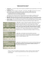
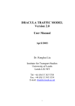
UK Distribution by:
IMA Ltd, Parkwell House, Otley Road, Guiseley, West Yorkshire, LS20 8BH, England
Tel: +44(0)1943 878877
Email: [email protected]
Website: www.ima.co.uk
PhyMetrix Portable Moisture Analyzer
Brief Instructions for Model: PPMa
USB, external Power, 4/20mA
IP67 connector.
Actual Display with the backlight
turned off; in the Graph mode.
Metal Dome snap membrane
switches.
Exhaust Pigtail
Gas Inlet
Sensor Knob, in the IN position
(Sensor is in desiccant).
Rev 1.2 Copyright © Phymetrix Inc. 2008
www.phymetrix.com
2
PhyMetrix Portable Moisture Analyzer
Brief Instructions - Performing a Measurement
Background Information:
A. In order to provide rapid moisture measurement in dry gases the analyzer is equipped with dry storage for
the sensor. When the sensor knob is pushed-in the sensor is in dry store, it should be left there while not in
use. When the sensor knob is pulled out (it moves out about ¾” or 19mm) the sensor is in the sampling
chamber. While following these instructions leave the sensor in dry store until the gas is hooked up and has
flowed through for a few minutes.
B. The analyzer has two gas ports, the upper port (closer to the display) should be used for the gas outlet
(exhaust). The lower port (closer to the sensor knob) should be used for the gas inlet.
C. It is assumed that the user is familiar with process analyzers, but it is important to emphasize that measuring
low moisture content in a gas requires extreme care and absolutely leak free hookup. When possible use
stainless steel tubing, if stainless steel is not possible then at least Teflon tubing should be used. Never use
copper, brass, silicone, tygon, nylon or other plastic or rubber tubing as they are permeable to water
molecules, and will cause erroneous measurements.
D. The analyzer gas ports are SAE/MS straight thread 5/16-24 ports. The analyzer is supplied with two
Swagelok O-Seal SAE/MS to 1/8” tube adapters which allow the user to attach 1/8” tubing to the inlet and
outlet ports. These adapters have Viton O-rings, if removed care should be taken to assure that they are not
damaged. Do not use these adapters with Teflon tape or sealing compounds.
E. When measuring moisture content below 10 PPMv (-60°C) it is advisable to place the provided pigtail on the
outlet port, to prevent moisture from the ambient to backflow into the sample chamber.
Connecting the Analyzer to the sample to be measured:
1. Hookup the gas to be measured to the analyzer inlet port adapter with 1/8” tubing.
Rotate the nut finger-tight, then while holding the fitting body steady
9
7
with a /16” wrench, tighten the nut three-quarters turn with a /16”
wrench (e.g. from the 12 o’clock position to the 9 o’clock position).
Make sure that the analyzer case/enclosure is not stressed while
loosening or tightening the fittings. Always use two wrenches.
2.
3.
4.
5.
6.
7.
8.
9.
Adjust the gas from its source such that there is 1 LPM or more of flow through the analyzer. If you need to
hookup a flow meter, do so at the exhaust of the analyzer as not to corrupt the reading.
Measurements should preferably be made at or near atmospheric pressure (no back pressure), but if
necessary the analyzer can measure with up to 150 PSI (10.3 Bar) pressure in the sample chamber. The
analyzer is optionally equipped with a pressure sensor and displays the measured pressure; it can also
compensate for the pressure and provide readings of the moisture content at a different pressure.
While the sensor is in dry storage, allow the gas to flow through the analyzer for a few minutes in order to
dry out the tubing and the analyzer sample chamber.
Turn ON the analyzer (refer to Brief Instructions User Interface). The display will show the moisture content
in the dry store.
Pull out the sensor knob (about ¾” or 19mm). The display will now show the moisture content of the gas in
the sample chamber. Step to the Graph Display Mode, and observe the trend graph shown in the middle of
the screen.
When the trend is stable, record your measurement.
When the measuring is completed, push the sensor knob back to dry store.
The sensor should not be left in mid position between the dry store and measuring position, as this will
cause the desiccant in the storage chamber to adsorb moisture from the ambient through the opening left in
this position. Always push the knob fully in or pull fully out. There is no need for excessive force, the sensor
knob should move about ¾” (19mm).
Rev 1.2 Copyright © Phymetrix Inc. 2008
3
PhyMetrix Portable Moisture Analyzer
Brief Instructions - User Interface
1.
TURNING ON - To turn ON the analyzer, press the left button (marked
the display comes on.
2.
TURNING OFF - When the analyzer is powered ON – if the left button (marked ) is held pressed for 4 seconds or
more the shutdown screen will appear and when the button is released the analyzer will power OFF.
When running on battery power, the analyzer will auto-shutoff if the user buttons are not pressed for:
2 minutes when the sensor is in Dry Store (in desiccant) or
5 minutes when the sensor is in the measurement position.
The settings for 2 and 5 minute auto-shutoff are factory defaults that may be disabled or modified by the user.
When operating from the external power source (USB connection to PC) the analyzer will not auto-shutoff.
BUTTONS - When powered ON, the analyzer screen shows a legend above each of the four buttons, these legends
depict the current function of each button, and serve as a guide to utilizing the analyzer. The left most button is almost
always allocated to “Help”, and it always serves as the power OFF button if held depressed for more than 4 seconds.
DISPLAY MODES - Once powered, the analyzer will enter one of three display modes (whichever was last used) that
show the measurements performed by the analyzer. Pressing the “Disp” button will change the display mode.
3.
4.
) and hold for approximately one second until
a. Display Mode - Pressure corrected and at pressure measurements, as well as the
gas pressure in the sampling chamber. The pressure correction selection in this
display mode will be also utilized in the other two display modes. If pressure
correction is enabled, then the status bar will provide an indication in all three display
modes, so that the user is made aware that the displayed measurement is pressure
corrected. In the example shown, the pressure in the sample chamber is 6.998 Bar
(101.5 PSI) as measured by the analyzer pressure sensor. The pressure dewpoint is
measured to be -61.1°C and the user has requested to know the dewpoint at
atmospheric pressure (1.013 Bar) which the analyzer calculated to be -74.3°Cdp.
b. Display Mode - Dual Dewpoint Units and Temperature of gas under
measurement. Note the status bar indicates that the measurements are pressure
corrected, as requested these are computed what they would be at atmospheric
pressure. The sample temperature is 20°C.
c. Display Mode - Single Dewpoint Units and Graph of the measured dewpoint in the
last 90 minutes, with a span of 20°Fdp. This is also pressure corrected. The graph
span will automatically resize to accommodate the minimum and maximum
measurements in the last 90 minutes.
Pressure Correction can be disabled in the “Display Mode – Pressure corrected” by using the “Step” button
to highlight the “Calc. to” units and using the ▲ and ▼ buttons until the upper display shows “Pressure
Correct disabled”.
Rev 1.2 Copyright © Phymetrix Inc. 2008
4
5.
6.
7.
8.
UNITS – The moisture content of the gas being measured can be displayed in a variety of units °C & °F
3
6
dewpoint, ppmV, ppmW, µB H2O vapor pressure, grams of H2O / m , and Lbs H2O /10 standard cubic feet in
Natural Gas. Use the “Step” button (right most) to highlight the units of the measurement and use the ▲ and ▼
buttons to change the units to the desired values. If the instrument is unlocked then the unit changes will be
permanent even if the analyzer is powered OFF. If the instrument is locked then the change will last for 5
seconds so the newly selected units can be viewed but the analyzer will reset the selection to the original units.
The status bar will indicate “Locked – change is temporary” and will produce beeping sounds.
LOCKING – The analyzers are shipped in the Locked mode from the factory, if desired they can be unlocked
via the system menu. Press the “Menu” button, then press the “Step” button a few times until the highlight bar is
over the “Un-Lock” menu selection, and then press the “Goto” button. If the analyzer is locked then the right
most button will be labeled “Unlock”. If the analyzer is unlocked then the right most button will be labeled “Lock”.
Use this button to change the state of the analyzer. There are also “OK” and “Cancel” buttons for completing the
locking / unlocking function. The analyzer may be left in the unlocked mode thus allowing easy permanent
changes of its setup. However if the analyzer is made available to many users with a mix of training on its use;
then it may be desirable to leave it locked.
MENUS – There are 3 menu screens providing various functions for operating the analyzer. To access MENU-1
press the “Menu” button when in any display mode. Then using the “Step” button move the highlight bar over
the desired function. Pressing the “Goto” button chooses the highlighted function. To access MENU-2 and
MENU-3 press the “Goto” button when the highlight bar is on the “More…” selection. Pressing the “Back” button
returns to the previous menu or to the display mode.
Read the full user’s manual for details on the functions provided in the menus. Much of it may be learned using
the PC emulation program available for training.
BATTERY – The analyzer uses a rechargeable Li-Ion battery. If the status bar displays a Low Battery message,
the battery should be recharged which can be done by plugging the analyzer into any computer’s USB port or
using the provided wall transformer.
Technical Specifications
Temperature Range
Moisture Sensor
Temperature Sensors
Pressure Sensor
Ergonomics
Electrical
Mechanical
Miscellaneous
Features
Enclosure: -40°C to +60°C
Electronics: -40°C to +85°C
LCD operating: -20°C to +70°C storage: -30°C to +80°C
Moisture Sensor: -20°C to +60°C
Pressure Sensor: -20°C to +85°C
Range -110°C to +20°C
Accuracy: ±2°C temperature corrected
Repeatability: 0.8°C
Response time: 95% of step change in 3 min.
Sample flow: >1 LPM
-40°C to +70°C ±2°C
0 to 300 PSIA ±1%, 316L stainless steel wetted parts
Comfortable to hold in hand, soft contoured body design, lightweight less than 2 Lbs
Easy to read graphic LCD display with user controlled backlight brightness
Snap dome tactile membrane switches with dynamically assigned legends
Audible feedback on button press as well as for warnings and alarms
Hook and magnet for easy temporary field securing / mounting
Auto scaling graph histogram on moisture measurement display for stability verification
Easy to use with verbose built-in context sensitive Help screens
Battery Saver, with user selectable Auto-power-down times, can also be disabled
Built-in pressure measurement and pressure corrected moisture readings simultaneously available with the uncorrected reading for greater ease of understanding
Verbose Status bar with indications, warnings and audible errors
User selectable locking with or without a password.
Built-in clock calendar
External AC Universal Power adapter supplied (100-240VAC 50-60Hz)
Rechargeable Li-Ion battery, recharges from the USB connection or from a universal power adapter
Sampling system and sensor are isolated form electrical interface and supply grounds
Measurement resolution of moisture sensor: 1pF resulting in less than 0.01°C
External power and I/O: USB mini B connector - IP67 / IP68
Enclosure
Impact resistant (>7 Nm to EN 50014) Polyamide 12, IP65/EN 60529 ATEX hazardous area use (Ex II 2 G) approved (PTB 02 ATEX 1076U), Flammability: UL 94 HB
Abrasion resistant Polycarbonate display lens
Dimensions- L: 7.36” (187mm) W: 4.17” (106mm) H: 1.97” (50mm)
Weight Total 1.75 Lbs
1/8” Swagelok® Inlet and Outlet fitting adapters for the SAE/MS 5/16-24 ports.
All 316 Stainless Steel and PTFE wetted parts, small surface area stainless steel sampling chamber for fast response time.
Integral Sensor retraction into desiccant storage chamber for fast response-time when measuring low moisture content.
NIST traceable calibrations
3
6
Units of measure: °C & °F dewpoint, ppmV, ppmW, µB H2O vapor pressure, grams of H2O / m and Lbs H2O /10 standard cubic feet in Natural Gas.
Digital & Analog I/O: USB, 4/20mA
Data logging – single point, multipoint, time stamping etc…
Virtual Analyzer PC software for training, allows the user to experience the exact interface on their own PC with voice help explanations
Rev 1.2 Copyright © Phymetrix Inc. 2008