1
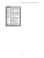
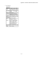
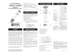
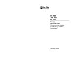
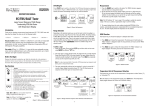
Riverside County Flood Control and Water Conservation District
Consolidated Monitoring Program
Volume II - QAPP
July 2014
APPENDIX H:
INSTRUMENT CALIBRATION AND
MEASUREMENTS
This Appendix represents current equipment used by the District
which may change as programmatic updates are implemented.
Appendix H – Instrument Calibration and Measurements
Omega HHWT-11 Handheld Chlorine Photometer
For operational instructions with graphics, along with important notes, please refer to the Operation
Manual which can be found online at the following website
http://www.omega.com/manuals/manualpdf/M5098.pdf
ISCO 3700 Portable Sampler
For operational instructions with graphics, along with important notes, please refer to the Operation
Manual which can be found online at the following website
http://www.isco.com/pcfiles/PartPDF/SL000004/UP0019H4.pdf .
H-1
Appendix H – Instrument Calibration and Measurements
Hydrolab Quanta Multi-Parameter Water Quality Monitor
For detailed instructions with graphics, along with important notes, please refer to the Operation
Manual.
A. Calibration
1. Ensure that the sensor probe is connected.
2. Wash the sensor in distilled water a few times and put some of the pH 4 standard solution into the
calibration beaker to the marked line.
3. Immerse the sensor in the calibration beaker.
4. Press the POWER key.
a.
Use arrow keys to select ‘CALIB’ and press Enter
b.
Select parameter you wish to calibrate and press Enter
c.
Use arrow keys to adjust reading to standard solution press Enter
5. Fully rinse probe and calibration cup with DI water then dry before filling with next standard solution.
a.
When calibrating pH calibrate 7.0 first then 10.0 or 4.0. (NOTE Quanta only does 2
point pH calibration)
b.
When calibrating DO sensor fill cup with DI water to O-ring of membrane on DO
probe. Use accurate mmHg to calibrate %DO this will calibrate mg/L DO at the same
time.
B. Measurement
1. Always attach the Guard to protect to the sensors before taking measurements.
2. Slowly immerse the sensor in the sample.
3. Turn the power on and allow measurements to stabilize.
4. Record the measurements on the Field Data Sheet while out in the field. Select the SCREEN
icon and use the ENTER key to switch measurement items.
5. After taking the measurement:
5.1 Turn the power off.
5.2 Use DI water to completely wash off the sample on the sensor and then wipe water drops.
5.3 Pour about 20 mL (about 2 cm from the bottom) of distilled water in the storage cup and
install it on the sensor probe and store the instrument in the carrying case.
H-2
Appendix H – Instrument Calibration and Measurements
C. Specifications
H-3
Appendix H – Instrument Calibration and Measurements
YSI 6920 V2 Multi-Parameter Water Quality Sonde
For detailed instructions with graphics, along with important notes, please refer to the User Manual.
A. Calibration
1. Ensure that the sensor probe is connected and sensor probe is fully immersed in standard solution.
2. Press the POWER key.
d.
Select Sonde Menu and press Enter
e.
Select Calibrate and press Enter
f.
Select parameter you wish to calibrate and press Enter
g.
Select 1-3 point calibration dependent on parameter and press Enter
h.
Type in standard solution value and press Enter
i.
Wait for readings to stabilize then press Enter to calibrate sensor
3. Fully rinse probe and calibration cup with DI water then dry before filling with next standard
solution.
a.
When calibrating pH calibrate 7.0 first then 10.0 or 4.0.
b.
When calibrating optical sensors (DO or Turbidity clean optics before calibrating)
c.
When calibrating DO sensor allow atmosphere in calibration cup to stabilize for
15 mins with DI water before calibration.
B. Measurement
1. Always attach the flow-thru Guard to protect to the sensors before taking measurements.
2. Slowly immerse the sensor in the sample.
3. Turn the power on and allow measurements to stabilize.
4. Record the measurements on the Field Data Sheet while out in the field.
5. After taking the measurement:
5.1 Turn the power off.
5.2 Use DI water to completely wash off the sample on the sensor and then wipe water drops.
5.3 Pour about 20 mL (about 2 cm from the bottom) of distilled water in the storage cup and
install it on the sensor probe and store the instrument in the carrying case.
H-4
Appendix H – Instrument Calibration and Measurements
C. Specifications
H-5
Appendix H – Instrument Calibration and Measurements
H-6
Appendix H – Instrument Calibration and Measurements
Horiba U-22XD Multi-Parameter Water Quality Monitoring System
For detailed instructions with graphics, along with important notes, please refer to the Operation
Manual.
A. Calibration
1. Ensure that the sensor probe is connected.
2. Press the POWER key.
3. Wash the sensor in distilled water a few times and put some of the pH 4 standard solution into the
calibration beaker to the marked line.
4. Immerse the sensor in the calibration beaker.
5. Press the CAL auto calibration mode key in one of the Measurement modes pH, COND, TURB,
DO. AUTO and CAL appear and the instrument enters the AUTO calibration mode.
6. Press the ENT key to start AUTO calibration. Upon completion of the pH, COND, TURB, DO,
and DEP modes, “End” will be displayed on the screen.
7. Press the MEAS key to return to the Measurement mode.
B. Measurement
1. Slowly immerse the sensor in the sample.
2. Select the measurement item. Use the MEAS key to switch measurement items in the following
order: pH, COND, TURB, DO, TEMP, DEP, SAL, TDS, σ, ORP, TIME, then back to pH.
3. After taking the measurement:
3.1 Turn the power off.
3.2 Use tap water to completely wash off the sample on the sensor and then wipe water drops.
3.3 Pour about 20 mL (about 2 cm from the bottom) of distilled water in the probe cap and install
it on the sensor probe. Place the rubber cap on the connector and store the instrument in the
carrying case.
4. Water quality data should always be recorded to the Field Data Sheet while out in the field. To
additionally manually store the measurement data (up to 2880 sets) in the instrument for later
download:
4.1 Make sure that MAN is displayed as the Measurement mode.
4.2 Press the ENT key. Data storage starts, DATA IN and the data set number is displayed on
the screen, and the measured value to be stored and the measurement item are displayed in
order at approximately 0.5 second intervals. After the data are stored to memory, the screen
returns to the original Measurement mode. Note the data set number on the Field Data
Sheet.
H-7
Appendix H – Instrument Calibration and Measurements
5. Viewing stored data on the Horiba (note that the data cannot be transferred to a PC, only to a
Horiba printer):
5.1 Press the DATA key in the Measurement mode. The instrument goes into DATA mode.
5.2 Press the DATA key. The measurement data are displayed. Data you want to call can be
displayed by selecting a measurement item and data number.
5.3 Press the UP/DOWN keys to switch the measurement item or number that has been selected
with the DATA key.
5.4 Press the DATA key. Use the UP/DOWN keys to switch between “Year, Month, Day’ and
“Hour, Minute, Second”.
C. Specifications
H-8
Appendix H – Instrument Calibration and Measurements
Oakton Waterproof pHTestr 2
For detailed instructions with graphics, along with important notes, please refer to the Operation
Manual.
A. Calibration
1. Before you begin: Remove electrode cap. To condition electrode, immerse electrode in electrode
storage solution, buffer, or tap water for at least 30 minutes. DO NOT USE DE-IONIZED
WATER.
2. Calibration: Calibration should be done regularly, typically every day that the Testr is used.
Calibrate the pHTestr 2 at three points (pH 4, 7, 10).
2.1 Press ON/OFF button to switch unit on.
2.2 Dip electrode 1/2" to 1" into chosen buffer (pH 4, 7, or 10).
2.3 Press CAL button to enter Calibrate (CA) mode. ‘CA’ flashes on the display. Then, a pH
value close to the pH buffer value will flash repeatedly.
2.4 After at least 30 seconds (about 30 flashes) press the HOLD/CON button to confirm
calibration. The display will show ‘CO’ and then switch to the buffer value reading.
2.5 Repeat with other buffers if necessary (pHTestr 2 only). Rinse electrode in tap water before
dipping into next buffer.
B. Measurement
1. Remove cap from the electrode and press the ON/OFF button to switch Testr on.
2. Dip the electrode 1/2" to 1" into the test solution. Stir once and let the reading stabilize.
3. Note the pH or press HOLD/CON button to freeze the reading. Press HOLD/CON again to
release the reading.
4. Press ON/OFF to turn off Testr. If you do not press a button for 8.5 minutes, the Testr will
automatically shut off to conserve batteries.
5. If possible, keep a small piece of paper or sponge in the electrode cap – moistened with clean
water or electrode storage solution (NOT DE-IONIZED WATER) – and close the cap over the
electrode.
H-9
Appendix H – Instrument Calibration and Measurements
C. Specifications
H-10
Appendix H – Instrument Calibration and Measurements
Oakton TDSTestr 20
For detailed instructions with graphics, along with important notes, please refer to the Operation
Manual.
A. Calibration
1. Before you Begin: Remove electrode cap. Switch unit on for 15 minutes to stabilize the batteries.
Soak electrodes for a few minutes in alcohol to remove oils. Caution: Never immerse the
electrode above color band as it will damage the instrument electronics.
2. Calibration: Your tester features push- button calibration at two points (one per range). Select a
calibration standard appropriate for each range: low range, between 150 to 1999 µS; high range,
between 2.0 to 19.99 mS. It is best to select a standard close to the test solution value, and one
that has a similar chemical make-up to the test solution.
2.1
Rinse the electrode in tap or deionized water, then in a known calibration standard.
2.2
Switch unit on (ON/OFF button).
2.3
Dip electrode into calibration standard. DO NOT immerse above color band!
2.4
Press CAL/CON button to enter Calibrate mode. ‘CA’ flashes on the display.
uncalibrated conductivity value close to the calibration standard value will flash.
2.5
Wait at least 30 seconds (about 30 flashes) for the reading to stabilize. Press the
HOLD/INC button repeatedly to adjust reading to match value of the known calibration
standard.
2.6
Press CAL/CON button to confirm calibration. The display will show ‘CO’ and then
switch to a calibrated conductivity reading.
2.7
For second range, repeat steps 1-6.
An
B. Measurement
1. Remove cap from electrode. Switch unit on (ON/OFF button).
2. Rinse the electrode in tap or deionized water, then in a small portion of test solution.
3. Dip the electrode into the test solution. Stir once and let the reading stabilize. DO NOT
immerse electrode above color band!
4. Allow time for the Automatic Temperature Compensation to correct the readings for solution
temperature changes.
5. Note the reading once the display is stable. Press HOLD/CON button to freeze the reading. Press
HOLD/CON again to release the reading.
6. Press ON/OFF to turn off Testr. If you do not press a button for 8.5 minutes, the Testr will
automatically shut off to conserve batteries.
H-11
Appendix H – Instrument Calibration and Measurements
C. Specifications
H-12
Appendix H – Instrument Calibration and Measurements
Hanna Instruments HI 98129 Waterproof pH, EC/TDS & Temperature Multimeter
For detailed instructions with graphics, along with important notes, please refer to the Operation
Manual.
A. Calibration
1. pH calibration:
1.1 From measurement mode, press and hold the MODE button until CAL is displayed on the
lower LCD. Release the button. The LCD will display pH 7.01 USE or pH 6.86 USE (if
you have selected the NIST buffer set). The CAL tag blinks on the LCD.
1.2
For a single-point pH calibration, place the electrode in any buffer from the selected buffer
set (e.g. pH 7.01 or pH 4.01 or pH 10.01). The meter will recognize the buffer value
automatically.
1.2.1 If using pH 4.01 or pH 10.01, the meter will display OK for 1 second and then
return to measurement mode.
1.2.2
1.3
A two-point pH calibration give better accuracy. For a two-point pH calibration, place the
electrode in pH 7.01 (or 6.86 if you have selected the NIST buffer set). The meter will
recognize the buffer value and then display pH 4.01 USE.
1.3.1 Rinse the electrode thoroughly to eliminate cross-contamination.
1.3.2
1.4
If using pH 7.01, after recognition of the buffer the meter will ask for pH 4.01 as
second calibration point. Press the MODE button to return to measurement mode
or, if desired, proceed with the 2-point calibration as explained below.
Place the electrode in the second buffer value (pH 4.01 or 10.01, or, if using NIST,
pH 4.01 or 9.18). When the second buffer is recognized, the LCD will display OK
for 1 second and the meter will return to normal measurement mode.
The CAL symbol on the LCD means that the meter is calibrated.
2. EC/TDS calibration:
2.1 From measurement mode, press and hold the MODE button until CAL is displayed on the
lower LCD.
2.2 Release the button and immerse the probe in the proper calibration solution: HI7031 (1413
µS/cm) for HI98129 and HI7030 (12.88 mS/cm) for HI98130.
2.3 Once the calibration has been automatically performed, the LCD will display OK for 1
second and the meter will return to normal measurement mode.
2.4 Since there is a known relationship between EC and TDS readings, it is not necessary to
calibrate the meter in TDS
2.5 The CAL symbol on the LCD means that the meter is calibrated.
H-13
Appendix H – Instrument Calibration and Measurements
B. Measurement
1. pH measurement:
1.1 Select the pH mode with the SET/HOLD button.
1.2 Submerge the electrode in the solution to be tested.
1.3 The measurements should be taken when the stability symbol on the top left of the LCD
disappears.
1.4 The pH value automatically compensated for temperature is shown on the primary LCD
while the secondary LCD shows the temperature of the sample.
2. EC/TDS measurement:
2.1 Select either EC or TDS mode with the SET/HOLD button.
2.2
Submerge the probe in the solution to be tested. Use plastic beakers to minimize any
electromagnetic interferences.
2.3
The measurements should be taken when the stability symbol on the top left of the LCD
disappears.
2.4
The EC (or TDS) value automatically compensated for temperature is shown on the
primary LCD while the secondary LCD shows the temperature of the sample.
H-14
Appendix H – Instrument Calibration and Measurements
C. Specifications
H-15