1
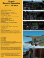
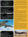
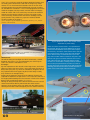
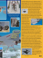
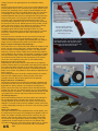
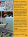
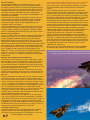
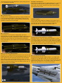
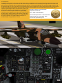
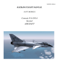
FSP
ilot
Magazine
Volume 1 : Issue 2
WIN
THE VERY LATEST
RELEASES
10 Competitions Inside this issue
Your chance to win a copy of the
Alabeo SU-26, Virtavia F111,
Razbam Buckeye, JustFlight DC6,
FlyingStations Buccaneer,
JustFlight Viscount, Sibwings Pitts,
and four other older releases the
Vertigo Studios Hawk & Hellcat.
UK2000 Heathrow & Gatwick
In this issue :
Alabeo Sukhoi SU-26
Carenado P46T Malibu
Flying Stations Buccaneer
Heathrow & Gatwick Extreme
MICROSOFT
Justflight DC6 & Viscount
Razbam T2 Buckeye
Vertigo Studios Hawk & Hellcat
Is now availble, but is it now a
Virtavia General Dynamics F111
Game or still a Flight Simulator?
Plus more....
FLIGHT
THE ALL NEW
F -111AARDVARK
for FSX win a copy
News, Views, Flight Simulator Addons - Commercial and Freeware
Virtavia
EF-111A
General Dynamics
F -111for FSX
Technical Specification : General Dynamics F111
General characteristics :
Crew : 2 (pilot and weapons system operator)
Length : 73 ft 6 in
Wingspan : Spread: 63 ft; Swept: 32 ft
Height : 17.13 ft
Wing area : Spread: 657.4 ft²; Swept: 525 ft²
Airfoil : NACA 64-210.68 root, NACA 64-209.80 tip
Empty weight : 47,200 lb
Loaded weight : 82,800 lb
Max. takeoff weight : 100,000 lb
Powerplant : 2 × Pratt & Whitney TF30-P-100 turbofans
Dry thrust : 17,900 lbf each
Thrust with afterburner : 25,100 lbf each
Zero-lift drag coefficient : 0.0186
Drag area : 9.36 ft² (0.87 m²)
Aspect ratio : Spread : 7.56, swept: 1.95
Performance :
Maximum speed : Mach 2.5 (1,650 mph) at altitude
Combat radius : 1,330 miles
Ferry range : 4,200 miles
Service ceiling : 66,000 ft
Rate of climb : 25,890 ft/min
Wing loading : Spread : 126.0 lb/ft² ; Swept : 158 lb/ft²
Thrust/weight : 0.61
Lift-to-drag ratio : 15.8
Armament :
Guns : 1× 20 mm M61 Vulcan 6-barreled gatling cannon in
weapons bay (seldom fitted)
Hardpoints : 9 in total (8 × under-wing, 1 × under-fuselage
between engines) plus 2 attach points in weapons bay with a
capacity of 31,500 lb (14,300 kg) and provisions to carry
combinations of:
Bombs :
Free-fall general-purpose bombs
Mk 82 (500 lb)
Mk 83 (1,000 lb)
Mk 84 (2,000 lb)
Mk 117 (750 lb)
Cluster bombs :
BLU-109 (2,000 lb) hardened penetration bomb
Paveway laser-guided bombs, including 2,000 lb GBU-10, 500 lb
GBU-12 and GBU-28, specialized 4,800 lb penetration bomb
BLU-107 Durandal runway-cratering bomb
GBU-15 electro-optical bomb
AGM-130 stand-off bomb
-------------------------------------------------------------------------------------he General Dynamics F-111 was an all-weather attack aircraft,
capable of low-level penetration of enemy defenses to deliver
ordnance on the target. The F-111 featured variable geometry
wings, an internal weapons bay and a cockpit with side by side
seating. The cockpit was part of an escape crew capsule. The
wing sweep varied between 16 degrees and 72.5 degrees (full
forward to full sweep).The wing included leading edge slats and
double slotted flaps over its full length. The airframe was made
up mostly of aluminum alloys with steel, titanium and other
materials used in places.The fuselage was made of a
semi-monocoque structure with stiffened panels
and honeycomb sandwich panels for skin.
T
01
F-111E
FB-111A
F-111C/G
F-111F
The F-111 used a three-point landing gear arrangement with a
two-wheel nose gear and two single-wheel main landing gear.
The landing gear door for the main gear was positioned in the
center of the fuselage and also served as a speed brake in flight.
Most F-111 variants included a terrain-following radar system
connected to the autopilot. The aircraft was powered by two Pratt
& Whitney TF30 afterburning turbofan engines. The F-111's
variable geometry wings, escape capsule, terrain following radar,
and afterburning turbofans were new technologies for production
aircraft.
USAF F-111 variants were retired in the 1990s with the F-111Fs
retired in 1996 and EF-111s retired in 1998. In USAF service, the
F-111 has been effectively replaced by the F-15E Strike Eagle
for medium-range precision strike missions, while the supersonic
bomber role has been assumed by the B-1B Lancer. The RAAF
was the last operator of the F-111, with its aircraft serving until
December 2010.
Weapons bay :
The F-111 featured an internal weapons bay that could carry
bombs, a removable 20 mm M61 cannon, or auxiliary fuel tanks.
For bombs the bay could hold two 750 lb (340 kg) M117
conventional bombs, one nuclear bomb or practice bombs. The
F-111B was to carry two AIM-54 Phoenix long-range air-to-air
missiles in the bay. The cannon had a large 2,084-round
ammunition tank, and its muzzle was covered by a fairing.
However, it was rarely fitted on F-111s.
The F-111C and F-111F were equipped to carry the AN/AVQ-26
Pave Tack targeting system on a rotating carriage that kept the
pod protected within the weapons bay when not in use. Pave
Tack featured a forward looking infrared (FLIR) sensor, optical
camera and laser rangefinder/designator. The Pack Tack pod
allowed the F-111 to designate targets and drop laser-guided
bombs on them. Australian RF-111Cs carried a pallet of sensors
and cameras for reconnaissance use.
The FB-111 could carry two AGM-69 SRAM air-to-surface
nuclear missiles in its weapons bay. General Dynamics tested an
arrangement with two AIM-9 Sidewinder air-to-air missiles
carried on rails in a trapeze arrangement from the bay, but this
was not adopted. Early F-111 models had radars equipped to
guide the AIM-7 Sparrow medium-range air-to-air missile, but it
was never fitted.
External ordnance :
Each wing was equipped for four underwing pylons. The inner
two pylons on each wing would rotate to align with the fuselage,
while the outer two were fixed. Each pylon had a capacity of
5,000 pounds (2,300 kg). Various bombs and missiles could be
carried on the pylons. Auxiliary fuel drop tanks with 600 US
gallons (2,300 L) capacity each were also able to be carried.
The design of the F-111's fuselage prevents the carriage of
external weapons under the fuselage. But two stations are
available on the underside for electronic counter-measures
(ECM) pods, and/or data link pods; one station is on the weapon
bay, and the other on the rear fuselage between the engines.
Photo : USAF - Public Domain
02
The F-111's maximum practical weapons load was limited, since
the fixed pylons could not be used with the wings fully swept.
Tactical F-111s were fitted with shoulder rails on the four inner
swiveling pylons to mount AIM-9 Sidewinder air-to-air missiles
for self-defense. Australian F-111Cs were equipped to launch the
AGM-84 Harpoon anti-ship missile, and the AGM-142 Popeye
stand-off missile. FB-111As could carry the same conventional
ordnance as the tactical variants, but their wing pylons were
more commonly used for either fuel tanks or strategic nuclear
gravity bombs. They could carry up to four AGM-69 SRAM
nuclear missiles on the pylons.
Source : Wikipedia - http://en.wikipedia.org/wiki/General_Dynamics_F-111_Aardvark under the CC-BY-SA license
Superb Afterburner effects, with variable nozzles
dependant on power setting.
F-111 external payload of BLU-107 Durandal concrete penetration
bombs. Photo USAF - Public Domain
Walkaround :
We will be doing our test flight from RAF Lakenheath , Suffolk,
England, where the F-111 was operated by the 43TFW up to
1992. Our aircraft is 702390 an F-111F.
Fuselage :
My first impression of this aircraft is how large it was, and it also
takes me back to the times when I use to see these aircraft on a
daily basis flying over my house in Oxfordshire, England. Where
they operated from RAF Upper Heyford, which today is sadly
only used as a car storage facility.
Starting at the pitot tube at the tip of the radome Virtavia have
captured the distinctive shape of the F-111s nose cone which is a
flat angled profile leading from the structure in front of the cockpit
down to the curved lower profile. (See screenshot)
Moving aft along the belly of the aircraft we first come to a small
antenna and almost directly behind that the strike camera
housing. Three quarters of the way back from the strike camera
housing to the nose undercarriage bay there is another antenna.
Destinctive nose profile of the F-111 AARDVARK
03
There are various variants of the F-111 represented in
this package, though most of the differences are in the
armaments and additional sensor packs which replace
the bomb bay. The Raven model however does have two
rear facing exhaust vents on each side of the fuselage
next to the bomb bay mounted electronics pod. Two
large side mounted antennas below the wing and in line
with the main gear. Four blister antennas, two on each
side of the vertical fin, plus the large antenna cluster
housed in or on the bulbous cowling at the top of the fin.
Two tear drop shaped antennas mounted on masts on
the front top surface of each wing in line with the in flight
refuelling port. Most of these items are indicated with a
yellow circle on the image of the Raven below.
Photo of Real F-111 Wing Glove
Bomb bay doors have ‘V’ profiles to allow for
the dropping of free fall nuclear weapons.
The doors also hinge to allow ground
clearance for ordinance loading.
Fuel dump valve and vent.
Exhaust nozzle detail.
ECM Antennas
Immediately behind the nose undercarriage bay is the bomb bay
which has two doors each having a ‘V’ shaped front profile.
These doors also hinge in the middle giving ground clearance for
ordinance loading. (See screenshot) The ‘V’ profile allows for large
free fall nuclear weapons to be carried. The bomb bay doors are
animated via ‘Shift + E3’. There animation is smooth and linear.
The door actuating mechanism at the rear of the bay is also
animated. Internal bay detail is good, created using textures and
some structure for the ordinance mounting and door actuators.
A short distance behind the bomb bay is the
Belly Anti-collision
belly anti-collision light which is nicely
light
modelled (See left) and has a reflective
texture. Next moving aft is the main
undercarriage bay which will be discussed
later. Further aft between the engine
exhausts is a fairing for the arrestor hook.
Also in this fairing is the tail skid which extends/retracts along
with the undercarriage. The hook fairing covers all but the hook
end, and when the hook is selected ‘Shift +Q’ the fairing opens in
the form of two doors, and then subsequently the hook is
extended down with the doors staying in an opened position. The
arrestor hook is simply
modelled and textured.
On each side of the rear
fuselage just on the curve
from the belly to the side
fuselage is a strake.(See right)
Moving upwards between
the two engine exhausts is
Rear strakes one on each side.
a titanium section which is
very nicely modelled and textured. At the rear base of this
section is the Fuel Dump Valve and outlet. (See left)
On the outboard side of the engine exhausts on both sides is a
fairing which contains ECM antennas. This fuselage fairing is
also the point at which the All Flying Tail actuation and pivot
system are housed. (See Main Screenshot Left)
Forward of this fairing on the top section of the side fuselage is
the wing glove, the object of this device is to seal the opening
into which the wing folds when the wings are extended or
partially extended. The real aircraft has a well defined slit in this
glove where the wing moves, but on the model its not so well
defined.
Moving onto the top surface of the fuselage the shaping as with
the rest of the fuselage is well defined and very smooth. Moving
forward from between the exhausts is the joining area of the
vertical fin. The joint is smooth and linear with no bleeding or
mesh issues. The front of the fin has a spine running along the
top of the fuselage of approx. 2 meters in length.
Forward of this in line with the front of the wing is the upper
anti-collision light, it is the same as that modelled on the belly.
On each side of the light there is a well defined grill which is part
of the model and not just a texture. From the light and grills we
move forward towards the jettisonable cockpit module, but
before reaching that we encounter a VHF antenna and then the
air to air refuelling port panel. This is a closed panel which is
opened when refuelling is required. The panel is animated in the
model via ‘Shift +4’. The animation is smooth and the detailing of
the panel is very nice with
structure and textures.
(See left).
All Moving Tail
Rear Warning Antennas
Wing Glove - On the real aircraft there is a very well
defined slit line where the wing moves. On the model
its not so well defined, but it doesn’t really spoil the
effect when the wing is moving..
Animated air to air refuelling panel
is well detailed.
There is an IFF antenna just
before the jettisonable cockpit
module. The modelling of the
jettisonable cockpit is very well
defined with nice smooth
curves, good
04
canopy structure with good glass tint and reflection effects.
Wings :
The wing structures of these F-111s are very well modelled, with
smooth profiles and curves. Obviously the unique feature of this
aircraft is its sweeping wing. In order to accommodate the full
forward position at the inner leading edge of the wing root there
is a spilt glove vane which opens when the wings are in the
extended position and acts as an aerodynamic fairing when the
wings are fully back. The wing of the aircraft has leading edge
slats along with full width doubled slotted fowler flaps. The
aircraft employs spoilerons and an all moving tail for controlling
the roll axis of the aircraft. Detailing of the wing includes, on the
upper and lower surfaces, slat / flap tracks, actuators, fairings
etc. which are nicely done. Also on the wing tip are the
navigation lights and formation strip lights which are nicely
modelled. All animations of the wings and surfaces are smooth
and linear, though the spoilerons seem quite rapid in their
movement.
The wing structure extends from the front of the moving root
leading edge glove vane to just behind the cockpit. (See right)
There is a secondary navigation light located part way along its
length and an intake pressure probe on the lower surface.
Engine Intakes and Engine Bay Cowlings :
The intake of the F-111 which was later fitted to all models is that
which is known as the Triple Plow I intake and blade. This was
the final version in the development of the F-111 intake which
had many issues on earlier models of the aircraft.This intake is
well modelled on the aircraft in this package, including the blade,
cone and intake shape. Inside the intake are fitted guide vanes
for streamlining the airflow into the compressor of the engine.
These are also modelled, along with an animated bitmap
depicting the engine compressor.
Depending on the variant there are also either three opening
auxiliary intakes doors on the forward outer edge of the intake or
the intake itself slides forward as an auxillary intake door. The
animation of these is smooth and there is no bleed around the
doors when closed. The position of these doors is dependant on
power settings.
The cowlings that cover the engine intake and later the engine
itself are well modelled and in reality are part of the lower
fuselage structure. Non of these panels can be opened.
Engine Exhausts and Nozzles :
The Engine exhausts and nozzles are beautifully modelled and
animated, with both the inner and external nozzle parts moving
dependant on power settings. On full power the afterburner
effect is to say the least very realistic with a well defined cone
coming from the rear. The nozzle leaves are very well modelled
and the textures are brilliant. The detail inside the nozzles is also
very good with the burner ring being visible and well textured.
All moving tailplane :
By having sweeping wings the aircraft couldn’t have ailerons in
the conventional sense, therefore the aircraft employs an all
moving tailplane for pitch and roll axis control. The all moving
tailplane is a simple surface with the addition of static wicks and
a small trailing edge cowling on each for the rear warning system
antennas.
Vertical Fin & Rudder :
The large vertical fin is well modelled with a smooth profile, and
the area where the fin joins the fuselage has a good line with no
bleed. The rudder is simple and has small movement for yaw
control. It also has two static wicks on the upper trailing edge.
On the Raven the large bulbous antenna housing is very well
modelled with smooth shaping, and has a rear position light.
The other models have at the top trailing edge of the fin, a bullet
housing for an IR scanner and a rear position
light.
05
Lower section
of glove vane
The wings and surfaces are
very nicely modelled, and
include, slats, full wing width
slotted flaps, top surface
spoilerons and the split
glove vane that opens when the
wing is fully forward.
Spoilerons
Formation lights
Another unique feature of
this aircraft is that it uses
the main undercarriage
door also as a speed brake.
Interesting concept
Here is a dusk shot to show the nav light
and formation lights, but also there can be
seen better details of the top flap section,
and the side mounted antennas which only
appear on the Raven model.
Main gear detail.
Nose gear detail.
.
Full wing width
double slotted flaps
Static Wicks
Landing Lts and Nose gear detail
Wing extends forward from the glove vane to just behind
the cockpit above the engine intake.
Second navigation light position both sides
Glove vane
Intake Probe
Undercarriage :
The undercarriage of the F-111 is slightly unconventional as both
the nose and main gears are on the aircraft centerline.
The main gear is of a heavy construction which when extended
has its wheels sitting just outside of the fuselage side profile.
The main gear is very well detailed as is the main landing gear
bay, which has very nice texturing as well as the actuation
devices, piping and structure. Animation of the main gear is very
nice with the main gear being pulled inwards before being
retracted forward into the bay. All animation is smooth and
sequential, being very similar to the real aircraft retraction /
extension, very well done indeed.
The nose undercarriage has been given the same treatment,
detailed mechanism, bay, texturing, and animation.
Cockpit :
The cockpits of these models are to say the least exceptional.
With five dedicated panel layouts, beautiful instruments, control
panels, consoles, HUD etc. this has to be among one of the best
panel representations I’ve seen for a while. The gauges are very
well reproduced with the effect of depth between the glass and
the indicating plate. The resolution of the gauge textures is very
high with almost no blurring even at maximum zoom.
A great many of the systems have functionality, but due to the
limits of FSX, there are too many options that the basic simulator
cannot handle. The supplied user manual gives a good clear
insight into the working aspects of the instruments, switch
panels, HUD, and other equipment within the cockpit.
It would be difficult to detail all in this review therefore during the
flight test we shall be looking at the basic aircraft functionality
and flying characteristics, leaving the detailed use of the systems
for the user to discover. As for the structure of the cockpit, it is
also very well modelled and detailed.The canopy frame is
structured with a lot of detailing right down to the air vents,
handles, piping, air ducts and canopy actuators, all are very well
modelled and textured. The side wall structures of the cockpit,
side consoles, center console, rear center console, control stick,
instrument panel cover, standby compass, and even the crew
seats are all modelled to a very high standard, including the
texturing.
The only part which is a very, very small negative in the cockpit
is the rear view mirrors which do not appear to change or show
anything. They are always sky blue, even when flying through
thick cloud and rain.
There are four or five cockpit views available depending on the
aircraft selected.
Also available on the panel are some sim hot spots which allow
you to get quick access to, view control stick, view kneepad,
view map, view radio stack, view ATC window, and view GPS.
The external stores can be jettisoned but this is not animated.
There is a jettison switch on the left hand corner of the cockpit
which simply removes the external stores.
All in all an excellent cockpit and panel combination.
Exterior Textures :
This package comes with eleven very high quality 2048 x 2048
liveries depicting aircraft from the USA and Australia. Attention to
detail in the texture set very good. On the model itself it is almost
impossible to find any texture distortions, stretching etc. All seem
to have been very finely tuned to blend exactly with the part that
they are to adorn. Another very small negative point with the
package is that in all areas the textures are just too clean and
could have benefitted from some weathering and staining
especially the landing gear and bays, they are just a too clean
when comparing the models with their in service big brothers.
But in saying that you won’t see many better texturing sets than
this one, even if they appear to be factory fresh.
Top marks for textures.
06
Exterior Lighting :
As we discussed before the navigation lights are very nicely
reproduced on the wing tips as are the rear position lights.
We forgot to mention that the second set of navigation lights on
the wing root structure from the forward wing glove vane to the
fuselage behind the canopy part way along its length are only
used when the wings are folded back and is automatically
controlled by wing position. The wingtip formation lights are not
effected by wing position.
The aircraft has three landing / taxi lights located on the front
undercarriage. The lights are well defined and textured with a
reflective lens effect though at night they appear as only as
small points of light, which is rather disappointing as the
navigation lights shine brighter.
The aircraft possesses various formation lights on the wing tip,
forward and rear fuselages, vertical fin and also on the upper
fuselage surface. These are controlled by a separate cockpit
switch on the lighting panel located on the rear center console.
External loads / weapons :
The F-111 models come with different variants and also different
weapon loads. The F-111 can carry an amazing amount and
variety of weapons and other stores such as jamming and
datalink pods, ejector racks and fuel tanks, many of which are
featured on the models in this package. The loadouts cannot
however be randomly chosen as they belong to whichever model
they are present on, although they can be toggled on/off using
the weapons jettison button on the left side of the cockpit main
panel. Toggling off will not affect the payload weight or CG
position, it is merely a visual feature. All weapons and associated
pylons etc. are very well modelled, with excellent detail and
texturing. Information on weapons will appear on the final page
of this review.
Sounds, Documentation and Extra Effects :
The sound set for this package has been produced by Turbine
Sound Studios who are renowned for the quality and realism of
their soundsets, and in this package they have done just that.
The soundset is brilliant in all aspects, internally and externally.
From engine sounds on startup, to taxi power, throttling up to full
power and the afterburner, all are great.
Not just the engines but all sounds are convincing, and really
realistic. Canopy opening, Wing movement, IFR panel opening ,
bomb doors, undercarriage, wind and even rain effects are all
top notch.
There is smoke effect on engine start up. The afterburner effect
as mentioned earlier. There is also a custom fuel dump effect
from the rear fuel dump valve which is controlled from inside the
cockpit. Though the best effect is the fuel dump and burn effect,
(See main Screenshot) this is achieved by pressing keystroke ‘i’, so if
you want to duplicate an Australian F-111 flying display you can
do it. The fuel dump selected from the cockpit reduces fuel
content, but dump and burn doesn’t, so can do it as many times
as you like, how cool is that. The dump and burn effect is
excellent and very effective when viewed from a distance to be
able to appreciate the length of the flames.
Documentation supplied with this add-on is a sixty-four page
user manual. Within this manual is an introduction, installation
guide and then information on the instruments, panels, systems
and operation of various of the equipments and a quick start
flying guide. The information supplied is sufficient for getting you
familiarized with the aircraft and systems but sadly it is not very
comprehensive and lacks performance charts etc.
Flying the Virtavia F-111 :
We will be making our flight from RAF Lakenheath in Suffolk,
England. Where the F-111F was operated up until 1992.
Fortunately within this package is a Lakenheath F-111F of the
48 TFW squadron serial 702390.
07
For this flight test we used an original copy of an F-111F Pilots
Operating Procedures which we purchased on the Internet.
After carrying out an exterior pre-flight inspection we climbed
aboard and settled into the internal security and pre-start
checks.
After completing these checks we moved on to the before
starting engines checklist and subsequently the engine starting
checklists. With both engines started with ground idle at 60%
of rpm, and the before taxi checklist completed we were ready
to taxi to the holding point. Opening the throttles to 70% of rpm
we started to move and with that rpm we taxied at a good
speed without having to apply too much braking. Whilst taxiing
we carried out the before take-off checklist and on arrival at the
hold are given permission for take-off. Lined up on the runway
we are ready to roll. Wing sweep for take-off is 16º with flaps at
25º. Nose wheel steering is recommended up to effective
rudder control at approx. 50-70 KIAS. The rotation speed in the
manual suggested for our weight a rotation at 150 KIAS.
Opening the throttle to the T/O position we released the
brakes, and with a rapid acceleration we soon reached the
suggested 150 KIAS. A gentle pullback on the control stick we
were soon in a positive rate of climb and accelerating to 200
KIAS. We retracted the gear and at the same time reduced our
power to 90% rpm as recommended in the manual to maintain
an airspeed of 260 KIAS in the climb with an ROC of over
4,000 ft/min at 10º pitch up.
We soon reached our initial desired cruise height of 30,000 ft
and engaged the autopilot AS (370 KIAS), Alt (30,000 ft) &
Our Lakenheath based F-111F that we used during our test flying seen
burning. Just look at the detail of the fuel vapor and the flame ef
HDG hold. The autopilot works as advertised controlling all
selected items. We then disengaged HDG hold whilst keeping
AS & ALT hold engaged and made some manual rolling to the
left and right using the control stick and got good responses
from the controls. The max roll input that we made was 30º.
The autopilot maintained AS & ALT hold during these
maneuvers. We subsequently disengaged AS & ALT hold and
made a 20º climb at 90% rpm which reduced our airspeed
back to 320 KIAS. Levelling out at 40,000 ft we re-engaged the
autopilot in AS & ALT maintaining level flight. Next we climbed
to our supersonic cruise height of 66,000 ft at which we should
be able to fly at Mach 2.1. During the climb with afterburner our
airspeed was 450 KIAS at over 5,000 ft/min at a pitch of 20º,
on levelling out at 66,000 ft we engaged AS, ALT & HDG hold.
Mach 2.1 at supersonic cruise height is that which is
recommended in the flight manual at 80% rpm. We therefore
tried disengaging AS hold and set the rpm to 80% to see the
maximum airspeed that we could achieve in level flight. After a
few minutes the speed stabilized at Mach 1.85 well below that
stated in the manual.
After disengaging the autopilot we trimmed the aircraft with
afterburner engaged until we reached Mach 2.1, subsequently
pulling back on the throttle to disengage the afterburner, but
were still indicating 100% rpm. After stabilization in level flight
at 66,000 ft we could only get Mach 2.05 and were using a lot
of fuel burn at 100% rpm, as stated above if you set 80% rpm
you can only achieve Mach 1.85 to Mach 1.87.
OK, with regard to maneuverability at these airspeeds, it is
n here dumping and
ffect, superb !
with no appreciable difference in roll or pitch rates. This puppy
flies well at all airspeeds and altitudes.
Next we tried to overspeed the aircraft, nose down with full
power until the simulated warning came on at Mach 2.2.
Making a descent to 20,000 ft we slowed the aircraft down to see
at what speed we would get a clean stall. It took some time but it
actually happened in the simulation at 117 KIAS. We then did a
full flap, wheels down dirty stall which in the simulation occurred
at 112 KIAS, so there wasn’t a big difference between the two
stall speeds. The aircraft shows no adverse reaction to the stall
e.g. wing dip etc. Recovery was simple with nose down and level
wings, applying power to level out the stall and recover.
After the stall tests we descended to 10,000 ft for some slow
speed maneuvers prior to returning to the field. At an airspeed
of 220 KIAS we carried out pitch and role maneuvers to compare
with the higher airspeed maneuvers carried out earlier. Control of
the aircraft was similar in its characteristics to the earlier test
except that the rates were slower and there was less tendency to
over control especially in a turn. The same as for the high speed
inputs, they were easier to anticipate and control after flying
within the regime for some time as you became accustomed to
the aircraft’s responses.
One final thing to do before returning to base and that was to
carry out the fuel dump and burn to see if it effects the aircraft.
I’ve always wanted to do that after seeing an RAAF F-111 doing
it at an air display. So at level flight 10,000 ft at 300 KIAS we
carried out the dump and burn and there was no significant
difference experienced in terms of handling or airspeed.
So with the fun over it was back to base for an approach and
landing.
Entering into the circuit at 300 KIAS with wings swept for landing
we descended towards the downwind leg controlling our
airspeed with speed brakes and power as necessary. Turning
downwind we extended the landing gear, slats and set our flaps
to 15º whilst reducing our airspeed to 250 KIAS. On starting the
turn to finals we selected full flaps and adjusted our approach
speed to 180 KIAS before lining up with the center line with a 10º
ARA at approx. 300 ft. Crossing the threshold and maintaining
the rate of descent the aircraft eventually entered ground effect
at about 30 ft above the runway, this causes a slight nose dip
which must be controlled until touchdown of the main wheels
with the runway is established. Upon contact allow the main
wheels to settle before lowering the nose of the aircraft. Whilst
applying the brakes we pulled back on the stick to achieve
aerodynamic braking from the all moving tailplane. Ground roll
spoilers will automatically extend. Maintaining directional stability
with the rudder and differential brakes until approx. 50 KIAS at
which time the direction is maintained using the nose wheel.
Once the aircraft had decelerated below 20 KIAS we were able
to taxi off the runway and return to the dispersal. On leaving the
runway the post landing checks were carried out before parking
at the dispersal, where the engine shut down procedures were
effected and the aircraft fully shut down and we deplaned. Total
flight time 2 hours 55 mins.
External loads and Weapons :
GBU-10, GBU-12 and AIM-9P :
The GBU-10 Paveway II is the 2,000 lb Mk.84 general purpose
iron bomb with a laser seeker head and guidance fins added.
This turns the 'dumb' bomb into a 'smart' bomb which is guided
to its target by airborne or ground-based laser target
designation. This is the larger of the bombs shown in the
foreground in the first picture on the next page.
The GBU-12 Paveway II is the smaller, 500 lb Mk.82 GP bomb,
fitted with the Paveway II kit as described above.
The AIM-9P is an advanced version of the Sidewinder infra-red
air-to-air homing missile.
08
The horizontal ejector racks added to the outer pylons give the
F-111 self defense capability.
Mk.82 500 lb bombs :
The Mk.82 is an unguided, free-fall bomb, usually carried on the
F-111's Multiple Ejector Rack in two groups of three per rack.
Two racks per wing are often carried, providing a devastating
fusillade of explosives onto the target.
Mk.82 Snakeyes :
The Snakeye is a normal Mk.82 500 pounder, but with a
high-drag tailfin unit which automatically deploys when the bomb
is released. This retards the speed of the bomb, allowing the
aircraft more time to pass over the target before detonation,
which allows delivery of the bombs at a much lower altitude than
normal Mk.82's.
GBU-15 and AXQ-14 Datalink Pod :
The GBU-15 is a 2,000 lb Mk-84 free-fall iron bomb with forward
and aft steering fins and TV or infra-red guidance system on the
nose. Signals are sent to the bomb from the AXQ-14 Datalink
Pod, which is usually mounted aft ventrally on the F-111. The
system enables the bomb to glide to its target, either as fire-andforget with automatic guidance once the target has been set, or
guided manually by the copilot.
09
AN-ALQ 131V ECM Unit :
This electronic countermeasures pod provides the F-111 with the
ability to jam and disrupt enemy ground and airborne radars.
First used in the 1970's, it remains one of the most successful
ECM systems ever made.
AGM-84 Harpoon :
This versatile radar-guided anti-shipping cruise missile can be
used by aircraft, ships, submarines and land batteries. The F-111
can carry four at a time and they are fully fire-and-forget,
skimming the sea at 537 knots for at least 67 miles.
AGM-69 Nuclear Stand-Off Missile (SRAM) :
Entering service in 1972, this missile was available in 17 and
210 kiloton versions and could be launched directly at the target
or in a semi-ballistic 'toss' maneuver. In both cases the missile's
own inertial navigation system would guide the single warhead to
its target, with a maximum range of 110 nautical miles.
B61 Free-Fall Nuclear bomb :
Developed during the early 1960's, the B61 is a multiple yield
weapon (0.3 to 340 kiloton) which can be carried externally at
supersonic speeds. The F-111 can carry the bombs both on wing
pylons and in its bomb bay. The weapon is still in the inventory
today as the B61 MOD 11, a nuclear 'bunker buster'.
In conclusion :
In concluding this review it has to be said that Virtavia have put together another great package. The standard of the overall
modelling is exceptional, the textures are well defined in high resolution with no stretching or misalignment. The sound set is
great, as are the available effects, especially the dump and burn. The aircraft model flies very well with no big surprises in all
envelopes of flight. The array of avionics in the cockpits were not fully tested in this review and have been left for the end user
to find out the functions should they buy the product. Again as with all add-ons of such high quality it has a manual which
contains a good insight into the aircraft and its systems, but
Available now by direct download:
fails badly on check lists and procedures for fully flying the
http://www.virtavia.com
aircraft. When will developers realize that a good flight
manual is just as important as a high quality model for us to
Price : EUR 29.45 download
be able to enjoy all the features of the aircraft. Putting this
aside its difficult to fault the Virtavia F-111, and I will surely
Technical Requirements : Recommended
be flying it regularly. An excellent add-on worthy of its
Flight Simulator X (Acceleration, SP2)
awarded rating. Congratulations Virtavia!
no technical specification given.
10