1
USNTPS-FTM-NO. 109
(PRELIMINARY)
U.S. NAVAL
TEST PILOT SCHOOL
FLIGHT TEST
MANUAL
SYSTEMS TESTING
NAVAL AIR WARFARE CENTER
AIRCRAFT DIVISION
PATUXENT
RIVER, MARYLAND
1
U.S. NAVAL TEST PILOT SCHOOL
FLIGHT TEST MANUAL
USNTPS FTM NO. 109
SYSTEMS TESTING
Written By:
DR. GEORGE MASTERS, DR.VERNON GORDON,
TIMOTHY LENAHAN, CDR DAVID CULBERTSON, and MICHAEL LANDMANN
This Flight Test Manual is published under the authority of the Commanding Officer,
U.S. Naval Test Pilot School, and is intended primarily as a text for the pilots, engineers,
and flight officers attending the school. Additionally, it is intended to be a reference
document for those engaged in flight testing. Corrections and update recommendations to
this manual are welcomed and may be submitted to:
Commanding Officer
U.S. Naval Test Pilot School
22783 Cedar Point Road, Unit ID 2168
Patuxent River, MD 20670-5304
Telephone: (301) 342-4411
January 2000
1
CONTENTS
CHAPTER 1 - INTRODUCTION
CHAPTER 2 - COCKPIT EVALUATION
CHAPTER 3- RADAR THEORY
CHAPTER 4 - AIR-TO-GROUND RADAR TESTING
CHAPTER 5 - AIR-TO-AIR RADAR TESTING
CHAPTER 6 - NAVIGATION SYSTEM TESTING
CHAPTER 7 - ELECTRO-OPTIC SYSTEM TESTING
CHAPTER 8 - ELECTRONIC WARFARE SYSTEM TESTING
CHAPTER 9 - ORDNANCE TESTING
CHAPTER 10 - NIGHT VISION DEVICE TESTING
CHAPTER 11 - RADAR CROSS SECTION TESTING (TO BE DEVELOPED)
CHAPTER 12 - SOFTWARE TESTING (TO BE DEVELOPED)
1
CHAPTER 1
INTRODUCTION
1
CHAPTER 1
CONTENTS
Page No.
1.1 WHY SYSTEMS FLIGHT TESTING ..................................................................... 1-3
1.2 FLIGHT TEST MANUAL OBJECTIVE ................................................................. 1-4
1.3 FLIGHT TEST MANUAL ORGANIZATION........................................................ 1-4
1.3.1 MANUAL ORGANIZATION .................................................................1-4
1.3.2 CHAPTER ORGANIZATION ................................................................1-5
1.4 EFFECTIVE TEST PLANNING ............................................................................. 1-5
1.5 RESPONSIBILITIES OF TEST PILOT/TEST FLIGHT OFFICER AND
FLIGHT TEST ENGINEER............................................................................................ 1-5
1.5.1 TEST PILOT/TEST FLIGHT OFFICER..................................................1-5
1.5.2 FLIGHT TEST ENGINEER.....................................................................1-6
1.6 SYSTEMS SYLLABUS........................................................................................... 1-7
1.6.1 OVERVIEW.............................................................................................1-7
1.6.2 USNTPS APPROACH TO SYSTEMS TESTING..................................1-7
1.6.3 FLIGHT BRIEFINGS ..............................................................................1-8
1.6.4 FAMILIARIZATION FLIGHTS .............................................................1-8
1.6.5 PRACTICE FLIGHTS .............................................................................1-8
1.6.6 EXERCISE FLIGHTS .............................................................................1-8
1.6.7 REPORTS ................................................................................................1-9
1.6.8 PROGRESS EVALUATION FLIGHT....................................................1-9
1.7 SYSTEMS FLIGHT TEST CONDITIONS AND PILOT TECHNIQUES ............. 1-9
1.7.1 INITIAL CONDITIONS..........................................................................1-9
1.7.2 ENERGY MANAGEMENT....................................................................1-9
1.7.3 DATA COLLECTION...........................................................................1-10
1.8 FLIGHT SAFETY .................................................................................................. 1-10
1.8.1 INCREMENTAL BUILDUP .................................................................1-10
CHAPTER 1
INTRODUCTION
1.1 WHY SYSTEMS FLIGHT TESTING
Aircraft system performance generally can be defined as the weapon system tasks
that the system must execute for successful mission accomplishment. Expected system
performance parameters must be an integral part of the weapon system design process.
Given the user’s performance expectations, the designer makes decisions regarding
system choices and design parameters. He must choose the types of systems installed on
the aircraft, their operating modes, the resolutions required for each system, and the
operator interface required to allow the aircrew to use the systems to best tactical utility.
All of these help tailor the design to give the system the desired performance
characteristics.
Actual aircraft system performance characteristics are not always the same as the
design or the predicted system performance characteristics. Therefore, there is a need for
systems flight testing to determine the actual performance. Systems flight testing is
defined as the process of determining aircraft systems characteristics, or evaluating the
aircraft’s and weapon system’s ability to accomplish its mission. Determining aircraft
systems performance depends upon fundamental knowledge in several disciplines,
including: radar, communications, electro-optics, and navigation. The test team must
understand the basic measurements, instrumentation techniques, and equipment used to
gather the data needed to determine the various elements of a system’s performance. The
team uses these disciplines to form the basis for the flight test methods and techniques for
systems flight testing.
Using appropriate test methods and techniques, the flight test team begins to answer
questions about the system's predicted or actual performance such as:
1. What is the maximum and minimum range of the radar?
2. What is the resolution of the radar and electro-optic sensors?
3. How accurate is the navigation system?
4. How easily can targets be designated and weapons solutions defined?
5. How accurate is the weapon delivery system?
The results of systems flight testing are used for several purposes:
1. Determine mission suitability of the aircraft.
2. Determine if the aircraft meets specific contractual systems performance
guarantees, or systems performance requirements as specified in the user generated
requirements.
3. Provide data to construct aircraft flight manuals for use by operational aircrews.
4. Determine techniques and procedures for use by operational aircrews to attain
optimum system performance.
5. Obtain research information to advance systems knowledge or to develop new
flight test techniques.
1.2 FLIGHT TEST MANUAL OBJECTIVE
The objective of the Systems Flight Test Manual (FTM) is to serve as a practical
reference guide for planning, executing, and reporting systems flight testing. The FTM is
intended for use as a primary instructional tool at the U.S. Naval Test Pilot School
(USNTPS) and as a reference document for those conducting systems flight testing at the
Naval Air Warfare Center Aircraft Division Center (NAVAIRWARCENACDIV) or
similar organizations interested in systems flight testing. It is not a substitute for systems
textbooks. Rather, the FTM summarizes applicable theory to facilitate an understanding
of the concepts, techniques, and procedures involved in successful flight testing. The
FTM is directed to test pilots, test flight officers, and flight test engineers (FTE); it deals
with the more practical and prominent aspects of systems issues, sometimes sacrificing
exactness or completeness in the interest of clarity and brevity.
The FTM does not replace the Naval Air Warfare Center Report Writing Handbook.
The FTM contains examples of systems performance parameters discussed in narrative
and graphic format. It contains discussions of the effect various systems parameters have
on mission performance and suitability, and a discussion of specification compliance
where applicable.
Since this FTM is a text for USNTPS, it contains information relative to operations
at USNTPS and NAVAIRWARCENACDIV; however, it does not contain information
relative to the scope of a particular USNTPS syllabus exercise or to the reporting
requirements for a particular exercise. Details of each flight exercise vary from time to
time as resources and personnel change and are briefed separately to each class.
1.3 FLIGHT TEST MANUAL ORGANIZATION
1.3.1 MANUAL ORGANIZATION
The FTM is organized to simplify access to desired information. Although there is
some cross referencing, in general, each chapter stands as a distinct unit. Discussions of
systems test techniques are presented together with pertinent background analytic
presentations. Most of the discussion applies to weapons systems in general; with
specific examples given where appropriate. The contents are organized in a classical
grouping and follow the chronology of the systems syllabus at USNTPS.
Chapter 1, Introduction, is an overview of the FTM including the objectives of
systems testing, flight test conditions and test technique, and use of confidence levels.
Chapter 2, Cockpit Evaluation, is a discussion of the techniques and issues involved
in evaluating the crew/vehicle interface.
Chapter 3, Radar Theory, is a discussion of the theory of radar operation.
Chapter 4, Air-to-Ground Radar Testing, is a discussion of test techniques used to
determine air-to-ground radar performance.
Chapter 5, Air-to-Air Radar Testing, is a discussion of test techniques used to
determine air-to-air radar performance.
Chapter 6, Navigation System Testing, is a discussion of the theory behind different
navigation systems, and the test techniques used to test these different systems. Included
are INS, GPS, Doppler, and LORAN systems.
Chapter 7, Electro-optic Systems Testing, is a discussion of the theory behind FLIR
operation, and the test techniques used to determine FLIR performance.
Chapter 8, Electronic Warfare Testing, is a discussion of test techniques used to
evaluate defensive sensors.
Chapter 9, Ordnance Testing, is a reprint of a training manual originally compiled to
teach ordnance flight testing at the Strike Aircraft Test Squadron.
Chapter 10, Night Vision Device Testing, is a discussion of test techniques used to
evaluate night vision goggles.
Chapter 11, Radar Cross Section Testing (to be developed)
Chapter 12, Software Testing (to be developed)
1.3.2 CHAPTER ORGANIZATION
Each chapter, with the exception of the three radar chapters, has the same internal
organization where possible. Following the chapter introduction, the second section gives
the purpose of the test. The third section is a review of the applicable theory. The fourth
discusses the test methods and techniques, data requirements, data reduction, data
analysis, and safety precautions applicable to those methods. The 3 chapters on radar are
organized differently. The first radar chapter covers theory for both air-to-ground and airto-air radars. The next two chapters cover air-to-ground and air-to-air testing in the same
manner as the sections on other sensors.
1.4 EFFECTIVE TEST PLANNING
To plan a test program effectively, sound understanding of the theoretical
background for the tests being performed is necessary. This knowledge helps the test
team establish the optimum scope of tests, choose appropriate test techniques and data
reduction methods, and present the test results effectively. Because time and money are
scarce resources, test data should be obtained with a minimum expenditure of both.
Proper application of theory ensures the tests are performed at the proper conditions, with
appropriate techniques, and using efficient data collection methods.
1.5 RESPONSIBILITIES OF TEST PILOT/TEST FLIGHT OFFICER
AND FLIGHT TEST ENGINEER
Almost every flight test team is composed of one or more test pilots and test flight
officers, and one or more project engineers. Team members bring together the necessary
expertise in qualitative testing and quantitative evaluation. To perform the necessary tests
and evaluations, the test pilot and test flight officer must know the applicable theory, test
methods, data requirements, data analysis, instrumentation, and specifications. The flight
test engineer must possess a thorough knowledge of the tasks required for mission
performance in order to participate fully in the planning and execution of the test
program.
1.5.1 TEST PILOT/TEST FLIGHT OFFICER
The test pilot/test flight officer is proficient in the required flight skills to obtain
accurate data. They have well developed observation and perception skills to recognize
problems and adverse characteristics. They have the ability to analyze test results,
understand them, and explain the significance of the findings. To fulfill these
expectations, they must possess a sound knowledge of:
1. The test aircraft and systems in general.
2. The total mission of the aircraft and the individual tasks required to
accomplish the mission.
3. Theory and associated test techniques required for qualitative and quantitative
testing.
4. Specifications relevant to the test program.
5. Technical report writing.
The test pilot/test flight officer understands the test aircraft in detail. They consider
the effects of external configuration on aircraft performance. They should have flight
experience operating many different types of weapons systems. By observing diverse
characteristics exhibited by a variety of systems, the test pilot/test flight officer can make
accurate and precise assessments of design concepts. Further, by operating many
different systems, they develop adaptability. When flight test time is limited by monetary
and time considerations, the ability to adapt is invaluable.
The test pilot/test flight officer clearly understands the aircraft mission. They know
the specific operational requirements upon which the design was based, the detail
specification, and other planning documents. Knowledge of the individual tasks required
for total mission accomplishment is derived from recent operational experience.
Additionally, they can gain knowledge of the individual tasks from talking with other
systems operators, studying operational and tactical manuals, and visiting replacement
pilot training squadrons.
An engineering test pilot/test flight officer executes a systems test task and evaluates
the validity of the results to determine whether the test needs to be repeated. Often the
test pilot/test flight officer is the best judge of an invalid test point and can save the test
team wasted effort. Their knowledge of theory, test techniques, relevant specifications,
and technical report writing may be gained through formal education or practical
experience. An effective and efficient method is through formal study with practical
application at an established test pilot school. This education provides a common ground
for the test pilot/test flight officer and Flight Test Engineer (FTE) to converse in technical
terms concerning system performance and its impact on mission suitability.
1.5.2 FLIGHT TEST ENGINEER
The FTE has general knowledge of the same items for which the test pilot/test flight
officer is mainly responsible. Additionally, the FTE possesses sound knowledge of:
1. Instrumentation requirements.
2. Planning and coordination aspects of the flight test program.
3. Data acquisition, reduction, and presentation.
4. Technical report writing.
These skills are necessary for the FTE to form an efficient team with the test
pilot/test flight officer for the planning, executing, analyzing, and reporting process.
Normally, the FTE is responsible for determining the test instrumentation. This
involves determining the ranges, sensitivities, frequency response required, and
developing an instrumentation specification or planning document. The FTE coordinates
the instrumentation requirements with the instrumentation engineers who are responsible
for the design, fabrication, installation, calibration, and maintenance of the flight test
instrumentation.
The FTE is in the best position to coordinate all aspects of the program because he or
she does not fly in the test aircraft often and is available in the project office. The
coordination involves aiding in the preparation and revision of the test plan and
coordinating the order of the flights. Normally, the FTE prepares all test flight cards and
participates in all flight briefings and debriefings.
A great deal of the engineer's time is spent working with flight and ground test data.
The FTE reviews preliminary data from ground tests and existing flight tests. From this
data, critical areas may be determined prior to military flight testing. During the flight
tests, the engineer monitors and aids in the acquisition of data through telemetry facilities
and radio, or by flying in the test aircraft. Following completion of flight tests, the
engineer coordinates data reduction, data analysis, and data presentation.
The FTE uses knowledge of technical report writing to participate in the preparation
of the report. Usually, the FTE and the test pilot/test flight officer proofread the entire
manuscript.
1.6 SYSTEMS SYLLABUS
1.6.1 OVERVIEW
The systems syllabus at USNTPS consists of academic instruction, flight briefings,
familiarization flights, practice flights, exercise flights, flight reports, and evaluation
flights. Each systems phase of instruction concludes with an individual evaluation flight.
Toward the end of the syllabus, a group formal oral presentation is given in the form of
an Operational Test Readiness Review (OTRR). The final exercise at USNTPS is a
simulated Navy Developmental Test IIA (DT IIA). This exercise incorporates all the
airborne systems instruction into the total evaluation of an airborne weapon system.
The systems syllabus includes exercises in air-to-ground radar, air-to-air radar, ESM,
navigation systems, and FLIR. The syllabus is presented in a step-by-step, building block
approach allowing concentration on specific objectives and fundamentals. This approach
focuses on individual systems characteristics at the expense of evaluating the total
weapon system. Progress through the syllabus is toward the end objective, the evaluation
of the aircraft as a weapon system in the mission environment. The details of the current
syllabus are contained in U.S. Naval Test Pilot School Notice 1542.
1.6.2 USNTPS APPROACH TO SYSTEMS TESTING
The USNTPS provides varied aircraft for systems testing, and, although the aircraft
are not new ones, USNTPS assumes it has not been evaluated by the Navy. The syllabus
assumes a DT IIA was not conducted and USNTPS is designated to conduct an OTRR
for systems performance. The aircraft is assumed designated for present day use.
Performance, stability and control, weapons delivery, and other testing is assumed to be
assigned to other test squadrons of NAVAIRWARCENACDIV. The student is charged
with the responsibility of testing and reporting on the systems performance
characteristics of the syllabus aircraft.
Mission suitability is an important phrase at NAVAIRWARCENACDIV, and its
importance is reflected in the theme of flight testing at USNTPS. The fact an aircraft
meets the requirements of pertinent Military Specifications is of secondary importance if
any systems performance characteristic degrades the airplane's operational capability.
The mission of each aircraft is discussed and students conclude whether or not the
systems performance characteristics they evaluate are suitable for the intended mission.
This conclusion is supported by a logical discussion and analysis of qualitative and
quantitative observations, drawing on recent fleet experience.
The evaluation of systems performance for comparison to specification
requirements, contract guarantees, or other systems require accurate quantitative data. At
USNTPS, every effort is made to test under ideal conditions with all instrumentation
operational, however, problems may arise occasionally which cause errors in the data. If
bad weather, instrumentation failure, or other factors result in large errors or excessive
data scatter, the student critiques the data, and, if warranted, the flight is reflown.
Precisely accurate data are not required before the data are presented in a student report.
However, it is important to know if errors in the data exist and their effect on the results.
The primary purpose of the systems syllabus at USNTPS is learning the basic supporting
theory and proper flight test techniques.
1.6.3 FLIGHT BRIEFINGS
Printed and oral flight briefings are presented by the principal instructor for each
exercise. The flight briefing gives specific details of the exercise and covers the
objective, purpose, references, scope of test, method of test, test planning, and report
requirements. The briefing also covers the applicable safety requirements for the exercise
as well as administrative and support requirements.
1.6.4 FAMILIARIZATION FLIGHTS
Familiarization flights are preceded by thorough briefings including: theory, test
techniques, analysis of test results in terms of mission accomplishment and specification
requirements, and data presentation methods. In flight, the instructor demonstrates test
techniques, use of special instrumentation, and data recording procedures. After
observing each technique, the student has the opportunity to practice until attaining
reasonable proficiency. Throughout the familiarization flight, the instructor discusses the
significance of each test, implications of results, and variations in the test techniques
appropriate for other type aircraft. Students are encouraged to ask questions during the
flight as many points are explained or demonstrated easier in flight than on the ground. A
thorough postflight discussion between instructor and students completes the
familiarization flight. During the debrief, the data obtained in flight are analyzed.
1.6.5 PRACTICE FLIGHTS
Each student is afforded the opportunity to practice the test methods and techniques
in flight after the familiarization flight and prior to the evaluation, or data flight. The
purpose of the practice flight is to gain proficiency in the test techniques, data
acquisition, and crew coordination necessary for safe and efficient flight testing.
1.6.6 EXERCISE FLIGHTS
Each student usually flies one flight as part of each exercise. The student plans the
flight, has the plan approved, and flies the flight in accordance with the plan. The purpose
of the flight is to gather qualitative and quantitative data as part of an overall systems
evaluation. The primary in-flight objective is safe and efficient flight testing. Under no
circumstances is flight safety compromised.
1.6.7 REPORTS
A fundamental purpose of USNTPS is to assist the test pilot/test flight officer/FTE
team to develop their ability to report test results in clear, concise, unambiguous technical
terms. After completing the exercise flight, the student reduces the data, and analyzes the
data for mission suitability and specification compliance. The data are presented in the
proper format and a report is prepared. The report process combines factual data gathered
from ground and flight tests, and analysis of its effect on mission suitability. The report
conclusions answers the questions implicit in the purpose of the test.
1.6.8 PROGRESS EVALUATION FLIGHT
The progress evaluation flight is an evaluation exercise and an instructional flight. It
is a graded check flight on the phase of study just completed. The flight crew consists of
one student and one instructor. The student develops a flight plan considering a real or
simulated aircraft mission and appropriate specification requirements. The student
conducts the flight briefing, including the mission, discussion of test techniques, and
specification requirements.
As the student demonstrates knowledge of test techniques in flight, the student is
expected to comment on the impact of the results on the real or simulated mission. The
instructor may comment on validity of the results obtained, errors or omissions in test
procedures, and demonstrate variations in test techniques not introduced previously.
During the debrief the student presents, analyzes, and discusses the test results. The
discussion includes the influence of the results on aircraft mission suitability.
1.7 SYSTEMS FLIGHT TEST CONDITIONS AND PILOT
TECHNIQUES
1.7.1 INITIAL CONDITIONS
Knowing the initial settings of the weapon system is important during systems test. It
allows for repeatability of test results by giving each operator a known setup from which
to deviate.
1.7.2 ENERGY MANAGEMENT
Proper energy management is critical to effective use of scarce flight test resources.
Energy conservation when progressing from one test point or condition to another allows
acquisition of a greater quantity of data.
The test pilot/test flight officer is mentally ahead of the aircraft and flight profile.
They are aware of the next test point and effect a smooth energy conserving transition
from point to point. A smooth transition between points might include trading airspeed
for an airspeed/ altitude entry condition for a succeeding test point.
The test should be planned to make maximum use of the entire flight profile. Tests
can often be combined to make best use of test time and assets.
1.7.3 DATA COLLECTION
Data collection in this Flight Test Manual is specified using manual methods, such
as kneeboard cards and portable tape recorders. You may have the opportunity to use
data extracted from the 1553 bus on the F-18. In the Test Squadrons you will have the
opportunity to use more sophisticated data gathering techniques, including high
resolution range tracking for precise positioning data, and instrumentation systems
designed to more accurately record the performance of the aircraft and its sensors.
Understanding the concepts presented here will help you determine the kinds of data
recording options you will have available to you in the Test Squadrons, and the accuracy
required for each type of test.
1.8 FLIGHT SAFETY
1.8.1 INCREMENTAL BUILDUP
The concept of incremental buildup is one of the most important aspects of flight
testing. Buildup is the process of proceeding from the known to the unknown in an
incremental, methodical pattern. Flight tests are structured in this manner. Testing begins
with the best documented, least hazardous data points and proceeds toward the desired
end points always conscious of the aircraft, aircrew, and evaluation limits. There should
be no surprises in flight test. In the event a data point yields an unexpected result or a
series of data points creates an unexpected trend, evaluation stops until the results are
analyzed and explained.
CHAPTER 2
COCKPIT EVALUATION
CHAPTER 2
CONTENTS
Page No.
2.1
INTRODUCTION.................................................................................................. 2-3
2.2
ANTHROPOMETRY ............................................................................................ 2-3
2.2.1 PURPOSE.................................................................................................2-5
2.2.2 THEORY ..................................................................................................2-5
2.2.3 PROPER LOCATION..............................................................................2-5
2.2.4 NATURAL DIRECTION-OF-MOTION RELATIONSHIPS .................2-5
2.2.5 SHAPE CODING .....................................................................................2-5
2.2.6 INADVERTENT ACTUATION..............................................................2-6
2.2.7 DISPLAYS ...............................................................................................2-6
2.2.8 CONTROL DISPLAY INTEGRATION..................................................2-6
2.2.9 ACTUATION FEEDBACK .....................................................................2-8
2.3
LABELING ............................................................................................................ 2-8
2.4
ENVIRONMENT................................................................................................... 2-8
2.5
LIGHTING............................................................................................................. 2-9
2.6
METHOD OF TEST .............................................................................................. 2-9
2.6.1 METHOD .................................................................................................2-9
2.7
TEST CONDITIONS ............................................................................................. 2-9
2.7.1 SAFETY CONSIDERATIONS................................................................2-9
2.8
DATA ANALYSIS .............................................................................................. 2-10
2.8.1 DATA COLLECTION ...........................................................................2-10
2.9
STATISTICAL ANALYSIS................................................................................ 2-14
2.9.1 ERROR ANALYSIS ..............................................................................2-14
CHAPTER 2
REFERENCES
1. Anthropometry of Naval Aviators, 1964,NAEC-ACEL-533.
2. Cockpit Anthropometric Survey of Model A-4C, A-6A, A-7E, AV-8A, F-4J,
F-DT, and OV-1OA Airplanes, ST-12OR-71.
3. Investigation of A-4 Aircraft Escape System Clearance Envelope, ST-53R-72.
4. Military Standard MIL-STD-1472C, Human Engineering Design Criteria for
Military Systems, Equipment, and Facilities.
5. Military Specification MIL-A-8806, General Specification for Acoustical Noise
Levels in Aircraft.
6.
Military Standard MIL-STD-203F, Aircrew Station Controls and Displays:
Assignment Location, and Actuation of, for Fixed Wing Aircraft, Fifth Edition,
U.S. Navy: 1973.
CHAPTER 2
COCKPIT EVALUATION
2.1 INTRODUCTION
The purpose of conducting a cockpit (cockpit is a general term for the particular
operator's station (e.g., PPC, TACCO, ECMO, B/N, RIO, etc.)) evaluation at TPS is to
acquaint the student with the evaluation of human engineering design requirements as
related to aircraft testing. Because the cockpit is the focal point of the man-machine
interface, it is the area which should receive maximum human engineering design
emphasis. Unfortunately, many individual cockpit items receive little or no emphasis
concerning human accommodation or compatibility. It is often not until all cockpit items
are assembled into a mockup or actual cockpit during design and testing evaluations that
human engineering design deficiencies become identifiable. Not until the working
relationships of controls, displays, lighting, and cockpit environment are analyzed can an
intelligent evaluation be conducted. Regardless of airplane or system performance and
potential, the man in the cockpit must accomplish the transfer function of changing
airplane potential into reality. Important variables which control this transfer function are
(1) capabilities and limitations of the aviator and (2) the cockpit design, which is the link
between action and reaction performed by the systems operator as a result of information
received and processed.
The primary airplane mission must be emphasized during human engineering
evaluation. Additionally, "worst case" events must be considered, such as degraded
system operation emergencies.
The most important general principle to keep in mind when performing any human
engineering evaluation is the concept of individual differences. We all tend to evaluate
items such as controls and displays from a very subjective viewpoint, i.e., our own
capabilities, limitations, and experience. The fact that system operators are all different
must be thoroughly understood when evaluating cockpits. Test pilots and engineers, in
particular, are perhaps not always entirely objective when it comes to admitting that
particular human engineering design deficiencies are problems as far as they are
concerned. The following differences are among the most important in cockpit
evaluation.
2.2 ANTHROPOMETRY
Body sizes very considerably. Reference 1 is a compilation of 96 body dimensions
based on measurements of 1,549 Naval Aviators. The data are presented in inches and
centimeters as well as percentiles.
Detail airplane specifications generally require that cockpits accommodate 5th
through 95th percentile sized aviators for older airplane cockpits and crew stations (prior
to 1970) and that 3rd through 98th percentile be accommodated in newer cockpits (since
1970). It is generally assumed that if one's body measurements, such as height and
weight, are 50th percentile (average) that all his dimensions will be 50th percentile; this
is not true. Uniformity in body dimensions is very rare; e.g., it is doubtful that if a
person's sitting eye height is 70th percentile that his functional reach will also be 70th
percentile. It is important to know one's own percentile ranks of body dimensions.
Physiological Training Units (altitude chambers) are equipped with anthropometric
measuring devices where you can be measured and have your measurements translated
into percentile ranks. The most important dimensions relative to aircrew station design
are:
a.
Total sitting height.
b.
Sitting eye height.
c.
Sitting shoulder height.
d.
Bideltoid diameter (shoulder width).
e.
Functional reach (grasp between thumb and forefinger).
f.
Fingertip reach ("pushbutton" reach with extended forefinger).
g.
Buttocks-to-knee length (sitting).
Only by knowing your own various percentile ranks can you make relative
judgments as to the overall anthropometric accommodation of a particular cockpit; e.g., if
you know your functional reach is 35th percentile and that you cannot reach a particular
control when fully restrained, you therefore know that anyone with a functional reach
less than 35th percentile, when fully restrained, also cannot reach the control.
Equipments exist which can objectively measure anthropometric parameters such as
reach distances, angles of vision, and ejection seat egress clearance (References 2 and 3).
Egress clearances in ejection seat cockpits are often jeopardized when modifications
such as cameras, control boxes, or other equipments are added to canopy rails, glare
shields, etc. Human engineering personnel are prepared to use particular equipments to
attain quantitative data in cockpit anthropometry evaluations.
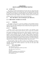
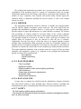
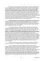
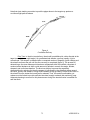
NOTE: It is critical that the Design Eve Position (DEP) be the source of
measurements for anthropometric evaluations. The DEP is the point in space where the
pilot's eyes should be positioned to see all displays and have adequate exterior vision. To
further define the DEP, other preliminary definitions are in order and are presented as
follows:
a.
Seat Reference Point is a center line intersection of the seat back tangent
line and seat surface.
b.
Neutral Seat Reference Point (NSRP) is the location of the seat reference
point when the seat is adjusted to the midpoint of vertical adjustments; e.g., with 5 in. of
vertical seat travel available, the seat would be adjusted to 2.5 in. above the lower limit.
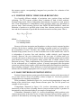
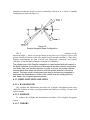
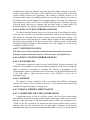
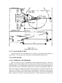
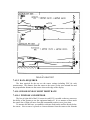
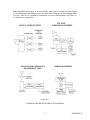
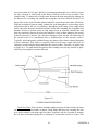
The DEP (figure 1) is then defined as the point in space located at the sitting eye
height dimension of the 50th percentile average aviator (31.5 in.) measured vertically
above the NSRP and 13 in. measured horizontally forward of the seat back tangent line.
All anthropometric evaluations must originate at the DEP. Whatever the size of the
individual evaluating items, such as control reach, display visibility, or cockpit space
accommodation, the seat must be adjusted to place his eyes at the DEP. The necessity of
adjusting the eyes to the DEP when making anthropometric evaluations is more critical
now than ever with the increasing emphasis on heads-up displays and other optical
devices which require strict adherence to line-of-sight criterion.
As with all human engineering evaluations, anthropometry must be checked against
"worst case" conditions. An example of a "worst case" condition would be reaching for a
critical control such as the emergency stores jettison when fully restrained (shoulder
harness locked) and when under a high-g condition such as a catapult launch.
Additional items of anthropometric deficiency include insufficient sitting height,
inability to reach rudder pedals or foot controls, inability to fit through emergency egress
openings, etc.
2.2.1 PURPOSE
The purpose of this test is to evaluate the controls, displays, and display symbology
for man/aircraft interface compatibility as defined by the assigned mission.
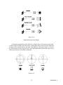
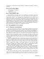
2.2.2 THEORY
As cockpits are designed, the anthropometric data of the aircrew are considered. The
50th percentile sitting height of 31.0 inches defines the cockpit Design Eye Position
(DEP) (figure 1). The center of vertical travel of the ejection seat generally places a man
with a 31.0 inch sitting height at the DEP. Compensation is required for sitting heights
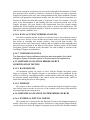
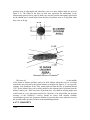
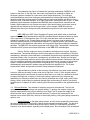
other than 31.0 inches. Controls which require manipulations while airborne should be
reachable from the DEP (figure 2). Controls utilized during Air Combat Maneuvering
(ACM) should be easily reached while performing high "g" maneuvers and while
maintaining a body position ready for safe ejection. The control operative sense should
conform to the standards presented in references 2 and 3. These standards generally
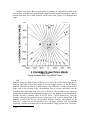
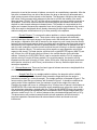
reflect expected response. Displays and controls which require monitoring or adjustment
airborne, should be placed inside a 30 degree cone centered on the Principal Line of Sight
(PLOS) (figure 3). Visual lookout and bogey acquisition, as well as display monitoring,
shall be considered in the placement of the PLOS. Displays should be large enough to
provide adequate detail as required by mission tasking. Displays are historically smaller
than desired because of area, weight, power, and cooling limitations.
2.2.3 PROPER LOCATION
Control placement should consider frequency and sequence of use. The design goal
is a reduction in the required movement of the eyes, head, and hands to perform a given
task. This is critical under high "g" loadings. The controls shouldn't require operator
movements which are uncomfortable or produce fatigue. Controls should never be
located such that the hand or arm manipulating the control is in the line of sight required
to see the display effect or setting of the control.
2.2.4 NATURAL DIRECTION-OF-MOTION RELATIONSHIPS
Actuating controls such as toggle switches forward or up should turn systems on.
Turning rotary controls clockwise should increase system output. Standard
direction-of-motion relationships should be adhered to in cockpit control actuation.
2.2.5 SHAPE CODING
Controls which may require manipulation without direct visual monitoring should
feel different to the touch if they are near controls of dissimilar systems.
2.2.6 INADVERTENT ACTUATION
Controls which can be activated incorrectly should be designed to prevent such
activation either by electronic circuitry or mechanical guards; e.g., forward wing-sweep
actuation during supersonic flight regimes which would potentially be damaging to
airplane components should be electrically or mechanically prevented.
2.2.7 DISPLAYS
Displays should be clearly visible when viewed from the DEP in bright daylight as
well as complete darkness. In clear daylight the sun positioned over the operator's
shoulder produces a serious glare problem for most displays. At night the display should
not be so bright that it distracts the operator, affects his night vision, or fills the cockpit
with light. Bright cockpits produce glare on the canopy which is tactically undesirable at
night. Display symbology alphanumerics must be clear, legible, and support mission
requirements. The information displayed must be sufficient for the task assigned yet not
overloading for the operator. This usually requires tailoring the display to a specific
attack mode/mission or phase of flight.
Display video and symbology are produced by organizing small dots of light (or dark
spots depending on display type) into recognizable patterns. The small dots are
mechanically organized into a matrix of columns and rows (called raster lines). The
larger the number of rows and columns, the smaller an individual matrix element
becomes. The display spot size defines the limit of the smallest matrix element and
available display resolution. Upon close inspection of the display glass, the row/column
matrix can be seen (a magnifying glass helps). By counting the number of raster lines per
inch and multiplying by the display size, the resolution in feet for a given display scale
can be found. This display resolution can then be compared to radar resolution. To take
full advantage of the radar design, the display resolution should be better than the radar
resolution.
Night Vision Goggles (NVG's) amplify ambient light levels produced by the stars,
the moon, and industrial sources. NVG light amplification provides the operator with
visual cues at night which resemble daytime cues. This permits Visual Meteorological
Condition (VMC) night low altitude flight as if clear daytime conditions prevailed.
Cockpit lighting, because of its close proximity and relatively bright intensity, can
degrade NVG use. Red or white lights appear as very bright sources to an NVG user.
Blue or green lights are NVG compatible. Due to the increased outside scan requirement
during an NVG low altitude flight, display symbology must be designed with maximum
clarity in mind. Cockpit lighting must be thoroughly evaluated to modify light sources
which distract the NVG user.
2.2.8 CONTROL DISPLAY INTEGRATION
The use of the controls and displays should be clear, requiring a minimum amount of
operator concentration. This leaves the operator free to make tactical decisions. The
controls should operate harmoniously with the other cockpit controls to allow
simultaneous operation of other airplane systems. This control integration should be
evaluated during mission relatable workloads while simultaneously operating all the
other aircraft systems.
Care should be exercised in determining proper safeguards to prevent inadvertent
actuation of controls, switches, etc., which might be actuated by flight clothing or items
of personal equipment, such as survival vests, flotation devices, anti-exposure garments,
etc.
2.2.9 ACTUATION FEEDBACK
Controls-should have proper tactical cues relative to actuation. One should "feel" the
lock of a toggle switch or push buttons without necessarily hearing it. Controls should
have the proper resistance and range of displacement as specified by Reference 4.
2.3 LABELING
Items of equipment which must be identified, manipulated, or located should be
adequately labeled to permit efficient human performance. Blueprints which illustrate
control panels often portray a straight-on-view. However, when the control panel is
installed in a cockpit, it is often offset from direct line of sight. The three dimensional
line-of-sight offset often results in labels (number, ON/OFF legends, or other
nomenclature) being obscured by the very controls to which they are related.
It is important to evaluate labeling legibility in low ambient light (dark) conditions as
well as in daylight. If an item must be labeled for normal daylight use, it should be
legible at night.
2.4 ENVIRONMENT
Heating, ventilation, and air conditioning shall be evaluated and compared with the
criterion specified in Reference 4 or in the applicable specification listed in the detail
specification of the airplane being evaluated. Hand-held instruments are available to
measure temperature as well as relative humidity. Specifications generally require an
Environmental Control System (ECS) to maintain between 60 and 80°F ambient
temperature in a crew station and 10° maximum differential between hand and foot level.
Interior ambient air should also be sampled throughout the flight regime or mission
profile of any aircraft. Carbon monoxide or other toxic fumes can be potential hazards,
particularly during operations such as taxiing downwind, gun or rocket firing, and during
refueling operations when directly behind a tanker.
Noise is the most serious and persistent problem among those associated with
aircraft environment. The maximum allowable noise limits relative to aircraft type are
described in Reference 5. It should be recognized that high noise levels of less intensity
than those specified as physically damaging to hearing can produce human fatigue and
degrade an aviator's effectiveness.
As a project officer, you should evaluate ambient exterior noise to which
maintenance or deck personnel are exposed as a result of being in the immediate vicinity
of the aircraft during ground operations. Maintenance personnel often neglect the
required ear protection because hearing loss is a slow insidious process.
Various levels of instrumentation are available in evaluating the acoustical
environment, ranging from small pocket sized decibel meters to sophisticated tape
recording devices that record noise samples which can be analyzed in detail for various
frequency bands.
NOTE: When conducting an interior noise survey, exercise any additional
equipments which may increase the acoustic level, such as air conditioning or defogging
systems, heater blowers, ambient air vents, and the extended configuration of in-flight
refueling probes.
2.5 LIGHTING
A concerted effort in the evaluation of cockpit lighting usually identifies numerous
lighting deficiencies. Often there is little emphasis on lighting evaluation. Typically,
during night flights general lighting observations are made by crewmen who are busy
flying or conducting other airborne tasks, thereby overlooking numerous lighting
deficiencies.
2.6 METHOD OF TEST
2.6.1 METHOD
The aircrew should perform the ground tests in full flight gear (gloves are important
for feedback cues) while seated at the DEP. Airborne tests may be performed with the
body positioned as required for mission accomplishment (i.e., aircrew comfort, ejection
envelope, maximum interior/exterior cockpit visibility). Comments on display control
utility when not seated at the DEP are pertinent. A bright clear day will enhance
evaluation of display brightness capacity. Night tests focus concern on display/canopy
interaction, cockpit ambient light levels, and Night Vision Goggle (NVG) compatibility.
All possible modes and display combinations should be evaluated. The dynamic effects
of "g" loading, roll, and pitch rates should also be evaluated.
2.7 TEST CONDITIONS
DAYLIGHT
-
GROUND TESTS
.
.
Cockpit Overview
First Impressions May Indicate
Areas of Operator Compensation
-
AIRBORNE
.
.
Evaluate Dynamic Response of System
Mission Utility
NIGHT
-
GROUND
.
.
.
Evaluate Cockpit Lighting Schemes
Canopy Glare
NVG Compatibility
-
AIRBORNE
.
.
Mission Utility
NVG Compatibility
2.7.1 SAFETY CONSIDERATIONS
The crewmember not directly involved in the evaluation shall assume primary
cockpit lookout responsibilities.
2.8 DATA ANALYSIS
2.8.1 DATA COLLECTION
A tape measure, protractor, and data cards will help record data during ground tests.
A voice recorder should be utilized airborne to record mission utility.
Controls - Make qualitative comments on following areas.
- Placement - are mission relatable controls centrally located?
- Functional Grouping - are functionally related controls grouped?
- Tactically Significant Control - Are these strategically placed for easy access?
- Frequency of Use - Is consideration given to placement of commonly used
controls?
- Sequence of Use - Does arrangement of controls reflect patterns of use?
- Distance Between Controls - Is it sufficient to prevent accidental use? Is it too far
to prevent rapid adjustments?
- Within Reach - Is it accessible to operator with defined anthropometric data?
- Operative Sense - Is forward, clockwise, to the right, or up = ON?
- Tactile Feedback - Control shape/size/movement/forces required.
- Control Movement - Range/breakout force/damping/friction/sensitivity.
- Fatigue - Does repeated control use produce fatigue/stress?
- Labeling - Are controls clearly and simply labeled?
- Manual Operation - Does it provide adequate control?
- HOTAS Operation - Does it reduce operator workload?
- Error Analysis - Does unintentional actuation of adjacent control produce
undesirable effects?
- Operative Utility - Does control provide adequate control of system throughout
flight regime?
- Aircrew Compensation Required - The first indication of a design oversight.
Displays - Make qualitative comments on the following areas.
- Brightness - Is a sufficient illumination range provided?
- Contrast - Are light/dark variations accurately presented?
- Resolution - Does provided raster lines/inch provide adequate detail to present
desired information?
- Spot Size - How does smallest element contribute to resolution?
- Screen Size - Can information be provided in adequate detail?
- Refresh Time - Does display flicker or smear? Is information timely and stable in
dynamic scenarios (roll rates, pitch rates, G's)?
- Sunlight - Does sunlight glare wash out display? Is operator required to
compensate for changing sun angles?
- Night - What is impact of display on cockpit ambient light levels; is canopy glare
produced?
- Automatic Brightness/Contrast - Does circuitry adequately compensate for
changing light levels?
- Target Video - Shape/size/brightness/contrast/movement characteristics.
- Automatic Gain - Does circuitry adequately compensate for situation dynamics?
- Manual Gain - Is sufficient range provided?
- Color - Is information clearly displayed without operator fatigue?
- Polarity - Does FLIR White/Black hot perform as advertised?
- Placement - Does placement complement inside/outside 30° cone of view from
DEP?
- Viewing Distance - Does placement require aircrew eyestrain to read information?
- DEP sensitivity - Is the display usable if not seated at the DEP?
- Information Load - Is too much information provided?
- NVG Compatible - Does lighting interfere with NVG's? Does information support
NVG flying?
- Utility - Is it functionally useful for aircrew?
- Mission Compatibility - Does symbology support mission requirements?
- NVG's - Lighting Compatibility/Functional utility with NVG's.
- Familiarity, clarity and usefulness in a tactically offensive environment - Does the
display provide the information where you want it, how you want it, when you want it,
while aggressively pursuing a target?
- Aircrew Compensation Required - The first indication of a design oversight.
Display Symbology - Make qualitative comments on following areas.
- Size - Is it large (small) enough to be effective?
- Brightness - Is the range of illumination sufficient?
- Clarity - Does it clearly present desired information?
- Resolution - Is it clear and legible?
- Placement - Is it easily viewed? Does it interfere with other information?
- Antenna Pointing Symbol - Does it provide adequate detail of antenna location?
- Weapon Envelope Cues - Does it provide sufficient missile/gun envelope
information?
- Steering Symbology - Is it clear, understandable, correct sense?
- Airspeed/altitude/velocity cues - Is target aerodynamics information presented
clearly?
- Dynamic Response - Does display symbology degrade under g loadings, roll rates,
etc.
A particular procedure which has been effective in static lighting evaluation is
described below.
1. Get into the airplane attired in the complete compliment of proper flight
clothing and equipment (take a tape recorder with you).
2. Have the canopy covered with an opaque cover preventing any ambient light
from entering. This allows you to conduct the evaluation day or night.
3. Have electrical power supplied to the aircraft to enable interior light actuation.
4. Adjust your seat to place your eyes in the design eye position (or where you
normally fly).
5. Allow your eyes to become adjusted to the dark (10 to 15 min).
6. Begin by locating the auxiliary light (if you can find it in the dark) and see if it
is suitable for minimum illumination if all other lights were lost.
7. After the auxiliary light evaluation, systematically exercise all light controls in
the cockpit. Vary the intensity, look for instrument lights on a particular rheostat which
extinguish before others when adjusting from bright to OFF. Look for brightness
imbalance such that, at a given light adjustment, some instruments may be too bright or
too dim when most other instruments on that particular lighting control are at a
reasonable intensity. Identify any glare or reflection which might possibly be shielded.
8. Verbally record on your tape recorder any deficiencies noted; this allows
evaluation uninterrupted by turning on floodlights or flashlights to write down
deficiencies which in turn would require readjustment of the eyes to low ambient light.
9. Adjust your seat to various positions to determine if lighting is sufficient
throughout a typical range of particular eye locations. This may be one of the few times
you evaluate lighting strictly for its own sake. Take as much time as is required to
evaluate all lighting variations, legibility of labels, visibility of controls, etc.
Data Reduction
Display Resolution
=
Scale (nm) x 6076 ft/nm
Size (inches) x resolution
(raster lines/inch)
Radar Range Resolution =
c x Pw
2
where
c = 161,875 nm/sec speed of Electromagnetic wave propagation
w = Pulse width (radar specific)
NOTE: Display resolution should be better than range resolution.
Results
1. Present crewmember anthropometric data.
2. Present flight equipment worn.
3. Define the ejection seat position (from bottom of seat travel in inches) required
to achieve DEP.
4. Define Test Conditions (i.e., weather, ambient light levels, ACM, etc.).
5. Controls Evaluation
6. Displays Evaluation
7. Symbology Evaluation
2.9 STATISTICAL ANALYSIS
N/A
2.9.1 ERROR ANALYSIS
N/A
CHAPTER 3
RADAR THEORY
CHAPTER 3
CONTENTS
Page No.
3.1
INTRODUCTION................................................................................................ 3-19
3.2
PURPOSE OF TEST............................................................................................ 3-20
3.3
THEORY.............................................................................................................. 3-20
3.3.1 PARAMETERS AND OPERATIONAL FEATURES OF AIRBORNE
RADARS..........................................................................................................3-20
3.3.1.1 OPERATIONAL MODES ........................................................3-20
3.3.1.2 CARRIER FREQUENCY .........................................................3-21
3.3.1.3 CARRIER POLARIZATION....................................................3-21
3.3.1.4 BANDWIDTH...........................................................................3-21
3.3.1.5 CARRIER POWER ...................................................................3-21
3.3.1.6 MODULATION ........................................................................3-21
3.3.1.7 PULSE WIDTH.........................................................................3-22
3.3.1.8 PULSE REPETITION FREQUENCY ......................................3-22
3.3.1.9 ANTENNA BEAMWIDTH ......................................................3-22
3.3.1.10 ANTENNA RADIATION PATTERN....................................3-22
3.3.1.11 ANTENNA SCAN PATTERN ...............................................3-22
3.3.1.12 ANTENNA SCAN RATES.....................................................3-22
3.3.1.13 DOPPLER BEAM SHARPENED AND SYNTHETIC
APERTURE RADAR BUILD TIMES...................................................3-23
3.3.1.14 ANTENNA SCAN ANGLE LIMITS......................................3-23
3.3.1.15 ANTENNA SCAN/DISPLAY STABILIZATION .................3-23
3.3.1.16 DISPLAY TYPES ...................................................................3-25
3.3.1.17 MOVING TARGET INDICATORS .......................................3-25
3.3.1.18 TRACK ACQUISITION MODES ..........................................3-25
3.3.1.19 PULSE COMPRESSION ........................................................3-25
3.3.1.20 DOPPLER BEAM SHARPENING AND SYNTHETIC
APERTURE RADAR.............................................................................3-27
3.3.1.21 INVERSE SYNTHETIC APERTURE RADAR (ISAR) ........3-27
3.3.2 PERFORMANCE CHARACTERISTICS OF AIRBORNE RADARS.3-27
3.3.2.1 GENERAL COMMENTS .........................................................3-27
3.3.2.2 RANGE DETERMINATION....................................................3-28
3.3.2.3 RANGE, ANGLE, AND VELOCITY GATING ......................3-28
3.3.2.4 RANGING ACCURACY..........................................................3-28
3.3.2.5 RANGE RESOLUTION............................................................3-30
3.3.2.6 MINIMUM RANGE .................................................................3-30
3.3.2.7 BLIND RANGES ......................................................................3-31
3.3.2.8 BLIND RANGE ZONE WIDTH ..............................................3-31
3.3.2.9 RANGE AMBIGUITY..............................................................3-32
3.3.2.10 MAXIMUM RANGE FOR DETECTION..............................3-32
3.3.2.11
3.3.2.12
3.3.2.13
3.3.2.14
3.3.2.15
3.3.2.16
3.3.2.17
3.3.2.18
3.3.2.19
3.3.2.20
3.3.2.21
3.3.2.22
3.3.2.23
3.3.2.24
3.3.2.25
3.4
BEARING/ELEVATION DETERMINATION......................3-34
BEARING/ELEVATION DETERMINATION ACCURACY3-35
ANGULAR RESOLUTION....................................................3-35
ANGLE AMBIGUITY ............................................................3-36
VELOCITY DETERMINATION ...........................................3-36
VELOCITY DETERMINATION ACCURACY ....................3-36
VELOCITY RESOLUTION ...................................................3-38
MINIMUM VELOCITY .........................................................3-38
MAXIMUM VELOCITY........................................................3-39
VELOCITY AMBIGUITY .....................................................3-39
BLIND VELOCITIES .............................................................3-39
BLIND VELOCITY ZONE WIDTH ......................................3-39
GROUND MAPPING QUALITY...........................................3-40
PREFLIGHT AND BUILT-IN-TEST .....................................3-41
SYSTEM INTEGRATION .....................................................3-41
TEST METHODS AND TECHNIQUES ............................................................ 3-41
3.4.1 GENERAL CONSIDERATIONS ..........................................................3-41
3.4.2 SAFETY CONSIDERATIONS..............................................................3-42
CHAPTER 3
RADAR THEORY
3.1 INTRODUCTION
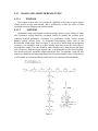
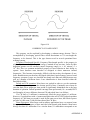
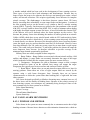
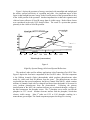
Modern multimode tactical radars have evolved considerably in the last few decades.
Air-to-ground radars have evolved from simple real beam pulse radars to sophisticated,
computer controlled systems employing complex digital signal processors. They
generally operate at a fairly low PRF, although it may vary depending on the range scale
selected. Pulse widths vary, but are generally short for increased range resolution. Small
target detection may require advanced techniques such as pulse compression, monopulse,
Doppler Beam Sharpening (DBS), or Synthetic Aperture Radar (SAR) techniques.
Inverse Synthetic Aperture Radar (ISAR) techniques may be used to image targets, such
as ships, that have rotational motion. Moving Target Indicators (MTI) may be used to
detect moving ground targets. The radars are usually highly integrated with the other
sensors on the aircraft and with the weapon delivery systems. The radar may be used to
provide initial pointing information to other sensors such as Forward Looking InfraRed
(FLIR). The radar may provide precise positioning data to allow updating a navigation
system. It may provide target position information to the weapon system computer so it
can develop the targeting solution. It may be possible to freeze the radar display to allow
target area study without radiating. For visual bombing, the radar may provide air-toground ranging (AGR) to allow the computation of a very accurate aircraft-to-target
range.
Air-to-ground radars are used for varied missions, including ground mapping,
ground attack, ground moving target tracking, anti-shipping and Anti-Submarine Warfare
(ASW), navigation, and weather avoidance. To improve covertness, Low Probability of
Intercept (LPI) techniques are being developed, based on limiting power or radiation
time, sweeping the transmit frequency, and increasing the signal-to-noise ratio to detect
weaker signals from more distant targets.
The operational requirements for a tactical air-to-air radar are different from those
for an air-to-ground radar.1 In some respects, the requirements are more stringent. The
target is likely fast-moving and highly maneuverable, and is not constrained to move on
the surface of the earth. The maximum range of interest is likely to be much greater,
thereby requiring greater transmitted power and the signal-to-noise ratio improvement
provided by coherent signal processing and precise and unambiguous velocity gating.2
Special requirements are imposed by air-combat maneuvers and tactics, and the need for
long-range target recognition. For use with a semi-active radar-guided missile, an air-toair radar must operate at a carrier frequency and waveform consistent with the design of
the missile. On the other hand, except for the air-to-air look-down or low altitude
situation, the background clutter is likely to be much smaller. Furthermore, because of
the weapons utilized, the long-range tracking accuracy requirements for air-to-air weapon
delivery are likely to be less stringent than those for an air-to-ground radar. (High
1 Airborne Systems course textbook: Principles of Radar System Test and Evaluation; Revised February,
1994, Section 3.3
2 Ibid. Section 3.3.2
resolution detection and tracking are generally required only for close-in gunnery and for
raid assessment.)
There are two basic philosophies currently applied to the design of air-to-air radars.3
In order to achieve long-range performance, the older design employs a high peak power,
a large pulse width, and a high PRF in order to obtain a high average power and to put
more pulses on a given target during search. At the same time, the high PRF avoids
ambiguous velocities and blind velocities.4 Unfortunately, the high PRF also creates a
severe ambiguous range and blind range problem. The newer design, employed in some
modes of the APG-65, employs a medium PRF, (to reduce the blind range/range
ambiguity problem), and avoids velocity ambiguities and blind velocities by utilizing
PRF agility. The APG-65 also employs automatic parameter selection that utilizes high,
medium, and even low pulse repetition frequencies in appropriate scenarios.5 The
advantage of this approach is that the PRF agility also avoids range ambiguities and blind
ranges. Long-range performance is achieved by the use of extensive signal processing
and velocity discrimination to increase the signal-to-noise ratio. These two basic
approaches result in different parameters and operational characteristics in the respective
radars. As a result of the extensive modulation and signal processing employed in the
APG-65, the operational characteristics of that radar are obscured, making it difficult to
detect and measure such characteristics as blind ranges, blind velocities, and the
maximum range for tracking. However, even though it may be difficult to measure, or
even to detect, these operational characteristics, it is important to test for them in order to
verify their presence or absence and to examine their effect on mission suitability.
3.2 PURPOSE OF TEST
The purpose of airborne radar testing is five-fold- (1) to determine specification
compliance, (2) to determine mission suitability, (3) to identify operational constraints
and limitations, (4) to evaluate the man/machine interface, and (5) to gather information
to be used in further testing and correction of the deficiencies and limitations identified in
test.
3.3 THEORY
3.3.1 PARAMETERS AND OPERATIONAL FEATURES OF
AIRBORNE RADARS
As a result of the mission requirements and design approach mentioned above, the
parameters and operational characteristics of a modern, multimode, frequency-agile radar
such as the APG-65 are generally consistent with those presented below. (See Section
3.13 of the Radar T&E text for definitions and a general description of these parameters
and features.)
3.3.1.1 OPERATIONAL MODES
3 Ibid. Section 3.3
4 Ibid. Section 2.16.10
5 Ibid. Section 2.13
Typical air-to-ground modes (those of the APG-65) are: Real Beam Ground Map
(RBGM), Real Beam Navigation Ground Map (RBNGM), Expanded modes (using DBS
and medium resolution SAR processing, called EXP 1, EXP 2, and EXP 3), Ground
Moving Target (GMT), Sea Surface Search (SEA), Ground Moving Target Track
(GMTT), Air to Ground Ranging (AGR), Precision Velocity Update (PVU), and Terrain
Avoidance (TA).
Typical air-to-air modes (again, those of the APG-65) are: Range While Search
(RWS), Velocity Search (VS), Track-While-Scan (TWS), Single-Target-Track (STT),
Air-Combat Maneuvering (ACM), and Raid Assessment (RA).
3.3.1.2 CARRIER FREQUENCY
Primarily air-to-ground radars such as those used in the A-6E and F-111 operate in
the J band (12 to 18 GHz). This allows a narrow beamwidth with a moderately sized
antenna. Tactical air-to-air and modern multimode radars generally operate in the X-band
(9 to 10 GHz) for compatibility with air-to-air missiles such as the Sparrow, Phoenix, and
AMRAAM. Narrow-band frequency modulation, at high PRF, is sometimes used, as
discussed in the section on modulation, to allow ranging on the FM waveform.
3.3.1.3 CARRIER POLARIZATION
Air-to-ground radars generally utilize horizontal polarization to enhance ground
returns. They may use circular polarization to improve all-weather operation. Air-to-air
radars generally utilize vertical polarization to reduce ground clutter returns in a lookdown or low altitude situation.
3.3.1.4 BANDWIDTH
Air-to-ground radars need high range resolution, hence narrow pulses, requiring a
high bandwidth (about 2 MHz). Despite the relatively large pulse width generally utilized
(for greater average power) and the absence of a requirement for high-resolution ranging,
the bandwidth of a modern air-to-air radar is generally narrow (about 1 MHz) in order to
allow the use of narrow-band filtering to reject noise, thereby increasing maximum range
and improving anti-jam performance.
3.3.1.5 CARRIER POWER
Older radars such as those in the A-6 and F-14 used relatively high transmitted
power (on the order of 100 kW). Modern multimode radars use much less power (5 to 10
kW), even though relatively large detection and track ranges are required, and rely on
signal processing to achieve large signal-to-noise ratios.
3.3.1.6 MODULATION
In order to maximize signal-to-noise ratio and provide for pulse-to-pulse ranging,
most airborne radars are pulsed. (Some air-to-air missiles require a CW support mode.)
Many air-to-air radars employ FM ranging at high PRF. The high PRF provides a high
average power and unambiguous velocity determination while the pulse-to-pulse
frequency modulation allows unambiguous range determination. The pulse repetition
frequency is often modulated (varied with time) to avoid range and velocity ambiguities,
as discussed in the section on general background.
3.3.1.7 PULSE WIDTH
Air-to-ground radars generally employ narrow pulse widths (as narrow as .1 µsec)
for high range resolution. In the absence of a requirement for high-resolution ranging, an
air-to-air radar generally employs a relatively large pulse width (about 2 µsec) to provide
the large average transmitted power required for long-range detection. In order to provide
more precise range information for tracking, it employs a somewhat smaller pulse width
(about 0.4 µsec) in the track mode. In order to trade range resolution for greater range at
long ranges, pulse width is often varied as a function of range. Pulse compression is
generally used to restore the range resolution lost by the use of larger pulse widths.6
3.3.1.8 PULSE REPETITION FREQUENCY
Air-to-ground radars generally use a very low pulse repetition frequency (PRF), from
several hundred hertz to a few KHz. PRF is often varied with range selected to avoid
second-time-around-echoes. Some air-to-air radars employ a high PRF (around 300 KHz)
in order to avoid velocity ambiguity and blind velocities. Other radars employ a medium
PRF (around 20 KHz) and avoid both range and velocity ambiguities by PRF agility. In
special situations, some air-to-air radars employ a low PRF (around 1 KHz) to avoid
range ambiguity.7 PRF is also sometimes varied with pulse width to maintain a constant
duty cycle.
3.3.1.9 ANTENNA BEAMWIDTH
The beamwidth of an airborne antenna is normally dictated by the carrier frequency
and the diameter of the largest antenna that can feasibly be installed in the aircraft.
Antennas in tactical aircraft are typically about two feet in diameter, and, at X-band,
produce beam widths of about 3.5 deg.
3.3.1.10 ANTENNA RADIATION PATTERN
The antenna radiation pattern is determined by the geometry and size of the physical
elements in dish antenna and by the carrier frequency; or by the geometry, size, and
phase relationships in a phased array. (See Section 3.13 of the Communication System
T&E text.)
3.3.1.11 ANTENNA SCAN PATTERN
Air-to-ground radars generally scan in a single bar pattern, with the tilt constant
depending on the range of interest. Air-to-air radars generally employ raster-scanned
(bar-scanned) antennas. Many radars use an interleaved-bar pattern, with signal
parameters that vary bar-to-bar, to avoid blind ranges, blind speeds, and scintillation
effects.8
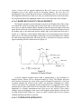
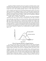
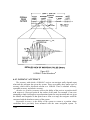
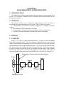
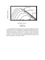
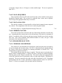
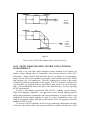
3.3.1.12 ANTENNA SCAN RATES
A radar utilizes echoes from a reflective target for detection. The amount of energy
received is a function of beamwidth and time-on-target (TOT). Time-on-target is the
6 Ibid. Section 2.10
7 Ibid. Section 2.3.4
8 Ibid. Section 2.13
antenna beamwidth divided by the antenna scan rate. The slower the scan, the longer the
antenna beam is on the target, the more energy hits the target, and the larger the number
of returned echoes that can be integrated and processed. This results in increased target
detection performance, but a decreased display update rate due to the slower scan rate. A
wide beam width may also lead to a decrease in real beam mapping quality due to the
decrease in azimuth resolution. The antenna scan rate determines the time on target for
any given beamwidth and, in conjunction with the scan angle, the refresh rate of the radar
display. The scan angle can be decreased to increase the frequency of updates with the
same scan rate if sufficient situational awareness can be obtained from the smaller area
mapped. A faster scan rate provides more frequent updates of target position or
navigation information but may sacrifice target detection due to the decreased hits and
reduced integration time available with which to build a consistent radar display. If the
scan rate is too slow, the operator may not be presented with the most up-to-date
information as a result of rapid aircraft movement. (For example, a radar with a 120 deg
scan with a scan rate of 60 deg/sec covers 1,600 ft between updates when traveling at 480
kt.) Measured scan rates may not match the specification due to antenna turnaround time,
the time it takes the antenna to stop and change direction at each gimbal stop. Some
manufacturers interpret the scan rate specification as applying to the rate at which the
antenna actually scans in between the stops, not the scan rate when you time more than
one scan.
3.3.1.13 DOPPLER BEAM SHARPENED AND SYNTHETIC
APERTURE RADAR BUILD TIMES
DBS radars and SAR have an update interval called the build time, the time between
successive refreshes of the display. DBS build times can vary depending on how the
mode is mechanized. A DBS radar may have a constant build time with varying
resolution, the resolution increasing with angle off the nose (called squint angle) and
antenna depression angle, or it may be mechanized to provide a constant resolution but
varying build time as the squint angle and antenna depression angle move further away
from the velocity vector. Build times can be mission related similarly to update rates.
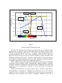
3.3.1.14 ANTENNA SCAN ANGLE LIMITS
The scan angle determines the width of the sector to be searched, and the amount of
aircraft heading change that is possible without losing contact with any given point on the
ground or area of the sky. Coupled with the scan rate, it also determines the update
frequency of the display. High scan rates and small scan angles generate the quickest
update frequencies. When utilizing a narrow scan angle to increase the update frequency
there is a tradeoff against the area covered, which may lead to loss of the "big picture"
and some situational awareness. Typically, as you move closer to your target with an airto-ground radar you need less of a big picture view, since the areas with which you are
concerned are identified, and you are more concerned about developing targeting
information based on a small area than you are concerned about mapping a large area. In
the air-to-air mission, once you have a contact and are prosecuting it, the search mission
is over and your concerns are maintaining contact on your target until it is destroyed.
3.3.1.15 ANTENNA SCAN/DISPLAY STABILIZATION
In most radar modes, the antenna scan and the display are stabilized with respect to
the ground rather than to the aircraft. (Actually, the frame of reference is stabilized with
respect to inertial space, in a plane parallel to the ground.) A stabilized frame of reference
is not only useful to facilitate interpretation of the display, but is essential to the weapondelivery task. If the weapon delivery computer had to perform its target tracking and
weapon delivery computations in the wildly gyrating aircraft coordinate frame, target
“lock” probably could not be maintained during violent air combat maneuvering. The
effects of vibration and “g”-loading also must be overcome.
Two basic methods of stabilization are commonly used. The older method is to
mechanically rotate the antenna to maintain a constant orientation with respect to the
ground. The newer method is to stabilize only the antenna scan and the display (not the
antenna itself) by software coordinate transformations (rotations) of the data. The end
result is the same from the viewpoint of the test planner. That is, both methods can
exhibit limitations on both the angle of rotation and the rate of rotation. The purpose of
an antenna stabilization test is to determine those limits.
The ability of a radar to display a usable ground map or maintain target tracking
during aircraft maneuvers relies primarily on antenna performance. When ground
mapping, the antenna must continue to scan in a stable orientation parallel to the horizon.
While trying to do this, antennas are limited by their range of motion, rates, and ability to
overcome load factor, or "g". Antennas have limits on their range of motion. Gimbal
stops, either mechanical or controlled by the servo motors or software, limit the range of
antenna motion possible. Elevation angle limits, or antenna tilt, are controlled by pitch
gimbal stops, and define the amount of steady state pitch angle an aircraft can attain, or
the amount of antenna look-down angle possible, and still maintain a stable radar picture
of the ground, or a scan parallel to the horizon. The lower limit of antenna tilt may
directly impact the minimum range of an air-to-ground radar. The upper limit has a
greater impact on scan volume in an air-to-air radar, but may impact air-to-ground modes
while doing maneuvers such as roll-ins. Lateral angle limits are similarly controlled by
gimbal stops or software stops, and result in limits on the horizontal scan angles possible.
These limits are typically tested during the scan angle tests, and are not usually
considered during stabilization tests. The servo motors must be able to position and scan
the antenna while coping with aircraft motion and the effects of antenna weight and
inertia. The servos have maximum rates of motion, and are limited in the amount of
“weight” they can handle. These limits affect the amount of aircraft maneuvering that can
be done before the antenna cannot maintain a correct scan orientation to the horizon.
Hopefully the antenna drive and control mechanisms have been scaled to take into
account the maneuvers necessary to perform the air-to-ground mission. At a constant
angle of bank, or during a rolling maneuver, the antenna is no longer scanning just in
azimuth with respect to the aircraft. The radar must mix elevation commands with
azimuth commands to maintain an antenna scan parallel to the horizon. Roll stabilization,
in constant-angle-of-bank flight, while rolling, is a measure of how well the radar is able
to maintain that scan when the aircraft is banked, or during rolling maneuvers. Note that
antennas may not be symmetric in vertical and horizontal dimensions. Typically, if they
are not symmetric they will be wider than they are tall to yield better azimuth resolution.
This may result in different mapping qualities as the antenna changes in relative
orientation with respect to the ground during rolling maneuvers, even though it should
still scan parallel to the horizon. The antenna's ability to maintain the correct scan
orientation is also dependent on the forces the servos are able to generate to overcome the
increased weight of the antenna due to load factor, or "g", during pitch maneuvers. The
servos must be able to match the aircraft pitch rates.
3.3.1.16 DISPLAY TYPES
Air-to-ground radars generally employ PPI Scan (Plan Position Indicator, a polar
plot of radial range and azimuth), sector PPI (a sector of a PPI display), depressed center
PPI (a sector of a PPI with the center at the bottom of the display), or sector patch (a
section of a PPI sector between 2 ranges) displays. Air-to-air radars generally employ BScan (range vs. azimuth), C-Scan (elevation vs. azimuth), PPI-Scan (polar plot of radial
range and azimuth), or B-Prime-Scan (velocity vs. azimuth) displays. In air-to-air
modes, the APG-65 employs a B-Scan as the primary display for all modes except the
velocity search mode, for which it employs a B-Prime-Scan. It also employs a C-Scan on
a second display. In air-to-ground modes the APG-65 employs a depressed PPI in MAP
mode, and a sector patch in EXPAND modes
3.3.1.17 MOVING TARGET INDICATORS
Many modern radars employ some sort of moving-target-indicator signal processing.
(All Doppler-filtering radars are moving-target indicators, although that term usually
implies the use of a delay canceller.)9 The intended effect of the moving-target indicator
signal processing is to eliminate non-moving targets, primarily ground clutter. A
sometimes unwanted effect is to create blind speeds--that is, target velocities at which
moving targets are invisible.
3.3.1.18 TRACK ACQUISITION MODES
In general (except for track-while-scan) an airborne radar cannot launch a weapon
while operating in a search mode. That is, the radar must be tracking a target. The
process of establishing a track on a given target is called track acquisition. In the APG-65
radar, air-to-ground tracking is accomplished by designating a point on the ground as
your target. A moving-target mode is also available to track moving ground targets.
There are four basic air-to-air acquisition “modes” or processes: manual acquisition, fast
acquisition, long range auto acquisition, and ACM acquisition. In manual acquisition and
fast acquisition, the target to be tracked is designated by the operator. In auto acquisition,
the target to be tracked is designated by the computer as the “priority” target, depending
upon the mode from which track acquisition was commanded (closest target from RWS,
most rapidly closing target from VS). In ACM acquisition, a prescribed search “volume”,
depending upon the ACM mode selected, is scanned and the first target encountered in
that volume is “locked-up”. ACM acquisition sub-modes are: boresight (BST), gun
(GUNACQ or HUDACQ), wide (WACQ), and vertical (VACQ). These ACM acquisition
modes differ in their search volumes and acquisition criteria and are optimized for
various ACM situations.
3.3.1.19 PULSE COMPRESSION
The energy in a radar pulse is proportional to the length of the pulse. The maximum
range of the radar, therefore, improves with increasing pulse length. The range resolution
of the radar, however, deteriorates with increasing pulse length. Most modern radars
employ a technique, known as pulse compression9, to obtain the maximum range of a
long transmitted pulse while retaining the range resolution of a short received pulse. In
order to be able to compress the received pulse, the transmitted pulse is “time-colored”
by intra-pulse frequency or phase modulation. There are both analog and digital
techniques for compressing such time-colored pulses. Compression ratios of about 50 to
1 are possible. When pulse compression is employed, range resolution tests must be
based upon the compressed pulse width, rather than the transmitted pulse width. The
minimum range and blind-range zone widths are unaffected by pulse compression.
9 Ibid. Section 2.16
3.3.1.20 DOPPLER BEAM SHARPENING AND SYNTHETIC
APERTURE RADAR
In the absence of special signal processing, the angular resolution of a radar is
limited by the beam width of its antenna. There are special signal processing techniques,
known as DBS and SAR, which greatly improve the angular resolution of a radar by
creating the effect of a very narrow antenna beam. The APG-65 radar utilizes either DBS
or SAR processing in its high-resolution ground-mapping modes. Doppler Beam
Sharpening utilizes the difference in the Doppler shifts of the ground returns, which
depend on angular offset from the ground velocity vector of the radar aircraft, to
distinguish between two points on the ground.10 An improvement in angular resolution
by a factor of about 100 is possible. Due to the relative insensitivity of the Doppler shifts
of ground returns in the direction of the ground velocity vector, DBS does not work well
in that direction. Many radars either blank the display in the region “off the nose” or
substitute a real-beam ground map in that area. Synthetic aperture processing creates the
effect of a very long antenna, (that is, very narrow beam width), by combining the returns
received at successive antenna locations as the radar aircraft moves.11 Angular resolution
tests in DBS and SAR modes should be based upon the beam-sharpened angular
resolution, rather than the real-beam resolution. Such tests also should evaluate the
effects of the “hole off the nose” and the effects of the characteristically long display
“build” times exhibited by both DBS and SAR radars.
3.3.1.21 INVERSE SYNTHETIC APERTURE RADAR (ISAR)
If an extended radar target is rotating, the radar returns from various points on the target
have Doppler shifts that are proportional to the distances of the points from the axis of
rotation. These Doppler shifts can be utilized, with the proper mathematical modeling, to
improve the angular resolution of the radar in directions transverse to the axis of rotation.
The technique is known as inverse synthetic aperture radar (ISAR). The process is “inverse”
to synthetic aperture radar in that it is the Doppler shift due to motion of the target that is
utilized, rather than the Doppler shift due to the radar aircraft. The information is displayed
as Doppler vs. range.
3.3.2 PERFORMANCE CHARACTERISTICS OF AIRBORNE
RADARS
3.3.2.1 GENERAL COMMENTS
As a result of the extensive signal processing employed in a modern, multimode
radar such as the APG-65, (range and velocity gating, carrier frequency agility, PRF
agility, pulse compression, digital frequency filtering, track extrapolation, and hit/miss
detection logic), some of the performance characteristics of such a radar are difficult or
impossible to determine in flight.12 For example, without extensive internal radar signal
instrumentation and range instrumentation, it is sometimes impossible to determine
10 Principles of Radar System Test and Evaluation, Section 2.18.1
11 Airborne Systems course textbook: Communication System Test and Evaluation, Section 2.6.13
12 Ibid. Sections 2.12 and 2.13
whether two targets were broken out (resolved as two targets) on the basis of range,
velocity, or bearing. For that reason, precise determination of some radar performance
characteristics is best performed on the ground, employing artificial target radar
stimulation.
In the following paragraphs, formulas are given for calculating, for test planning
purposes, the major performance characteristics of an airborne radar.13
For convenience in converting units, the following conversion factors are presented.
1 nmi
= 6,076 ft
1 kt
= 1.69 ft/sec
1 ft
= 1.64 x 10⁻⁴ nmi
1 ft/sec
= 0.59 nmi/hr
c
= 3.00 x 10⁸ m/sec
c
= 9.84 x 108 ft/sec
c
= 1.62 x 10⁵ nmi/sec
c
= 5.83 x 10⁸ nmi/hr
3.3.2.2 RANGE DETERMINATION
The range to a given target is determined by “time-coloring” the transmitted signal
and measuring the elapsed time between the transmission of the signal and the reception
of the corresponding return.14 Thus, the range to a given target is given by the equation:
R = c (∆t) / 2 (ft)
where: c = 9.84 x 108 ft/sec and (∆t) = Elapsed Time (sec)
(The range can be obtained in nautical miles by utilizing c = 1.62 x 10⁵ nmi/sec.)
3.3.2.3 RANGE, ANGLE, AND VELOCITY GATING
Most modern radars determine range by “gating” the receiver on for a brief time
interval. The elapsed time between the time of the transmitted pulse and the time of the
“gate” is varied (swept) until the return from the target is “captured” in the gate. The time
at which the target return is “captured” indicates the range to the target. The same timesweeping process is applied to the determination of the bearing (angle) of the target and a
similar process (sweeping frequency) is applied to the determination of the velocity of
the target.15
3.3.2.4 RANGING ACCURACY
The accuracy with which a radar can determine the range to a target is determined by
the accuracy with which the radar’s intervalometer can measure elapsed times and by
anomalous delays in the hardware. Because such information is not usually available to
the tester, an estimate of the ranging accuracy of a given radar, for test planning
13 Ibid. Sections 2.3 to 2.15 for definitions and a general discussion of these characteristics.
14 Ibid. Section 2.3.1
15 Ibid. Sections 2.14 and 2.17.8,9, and 10
purposes, is best obtained from the manufacturer. When an operator is involved in the
process, the ability of the operator to “read” the display may be a significant factor.
3.3.2.5 RANGE RESOLUTION
Range resolution is the minimum separation in range between two objects that can
be resolved as two objects on that basis.16 For a simple pulse-ranging radar, range
resolution is a function of pulse width.17 For such a radar, the range resolution is given by
the equation:
∆R = c τp / 2 (ft)
where τp is the pulse width in seconds and c = 9.84 x 108 ft/sec.
For an FM-ranging radar, the range resolution depends upon the ability of the signalprocessing circuitry to discriminate between two frequencies.18 The calculation of the
range resolution for such a radar therefore requires information not usually available to
the tester. When an estimate of the range resolution is required for test planning purposes,
it is best obtained directly from the manufacturer of the radar.
In addition to the signal processing limitations of the radar, the radar display has a
limited ability to individually display two closely-spaced targets, and thus has a
significant effect on observed resolution. The display may be the limiting factor in
determining the ability of an operator to resolve two targets. The display resolution
depends not only upon the characteristics of the display screen, but also upon the scale
being displayed. The radar display has a finite number of vertical pixels, and the ratio of
the number of vertical pixels per nautical mile of radar display is dependent on the range
scale selected. This ratio is an ultimate limit on observed range resolution of the radar.
The effective resolution must be determined for all relevant modes of operation and
display settings. Range and azimuth resolution should also be matched to show targets in
correct proportion.
Expanded display modes such as ARE 30 (Automatic Range Expansion) and ARE
60 in the A-6 increase the display resolution (at some expense to position and shape
fidelity), yielding an increase in range and azimuth resolution of the radar in these modes.
Internal signal processing quantities are sometimes recorded in radar test to see if the
radar breaks out targets the operator is not able to recognize because of display resolution
problems.
3.3.2.6 MINIMUM RANGE
The minimum range is that range below which a target cannot be detected due to
eclipsing. The minimum range is caused by the transmitting interval blanking the
receiver and is present in all pulsed radars.19 The minimum range is given by the
equation:
Rmin = c τp / 2 (ft)
16 Ibid. Section 2.3.3
17 Ibid. Section 2.3.3
18 Ibid. Section 2.11.3
19 Ibid. Section 2.3.2
where τp is the pulse width in seconds and c = 9.84 x 108 ft/sec .
Minimum range is important because it determines the operator's ability to track a
target all the way to weapon release, or to be able to track a target until you are able to
visually confirm the target, especially when operating under conditions of restricted
visibility.
There are factors other than eclipsing that affect minimum range. The smallest
display range scale available must be small enough to allow you to see the target all the
way to minimum range. The antenna tilt mechanism must allow the antenna to point at
the target all the way to minimum range, also. Receiver gain and video gain must be
adjustable to a small enough value to reduce blooming, which would obscure the target in
the background clutter.
3.3.2.7 BLIND RANGES
Blind ranges are those ranges at which a target cannot be detected due to eclipsing.
Blind ranges are caused by the transmit intervals blanking the receiver and are present in
all pulsed radars for which special signal-processing, such as PRF agility, has not been
provided.20 (Minimum Range is sometimes called the zero-order blind range.) The ranges
at which blind ranges occur are given by the equation:
RB = n c / 2 fr (ft) for n = 1, 2, 3, ... .
where fr is pulse repetition frequency in pulses per second and c = 9.84 x 108 ft/sec.
Blind ranges should not be a problem in an air-to-ground radar if the PRFs were
suitably chosen for each range scale. Nevertheless, the theoretical blind ranges should be
calculated to see if they are within the display range of the radar.
3.3.2.8 BLIND RANGE ZONE WIDTH
The width of the blind range zones is a function of the pulse width and is given by
the equation:
∆RB = c τp / 2 (ft)
where τp is the pulse width in seconds and C = 9.84 x 10⁸ .
In some radar modes, such as those in the APG-65 in medium PRF, the blind range
zones and the blind velocity zones are interdependent. That is, the blind zones are
dependent on both range and velocity. The coupling is caused by three factors: (1) the
dependence of both the blind ranges and blind velocities on PRF, (2) the use of multiple
PRF’s (8 in the APG-65) in an attempt to avoid both blind/ambiguous ranges and
blind/ambiguous velocities, and (3) the use of hit/miss detection logic (3-out-of-8 in the
APG-65) to reduce false alarms. The result is that, when such signal processing is
employed, the blind zones of the radar can best be represented on a “map” of blind
20 Ibid. Section 2.3.4 and 2.3.8
“zones” as a function of range on one axis and velocity on the other axis. In order to
“plot” such a map, a very large amount of data are required over a large range of values
of range and velocity.
3.3.2.9 RANGE AMBIGUITY
Range ambiguity is an anomalous indication of range caused by second-time-around
radar returns (STAE). That is, the radar signal processor treats a return from a previous
transmitted pulse as if it were from the latest transmitted pulse, thus measuring a
shortened time interval and indicating a reduced range. An ambiguous range is related to
a blind range. That is, if the range to a target is great enough that the return pulse
coincides with the transmitting interval, it is a blind range. If the range to a target is even
greater, so that the return pulse arrives after the next transmitting interval, the indicated
range will be ambiguous.21 In a pulse-to-pulse ranging radar, the maximum unambiguous
range depends upon pulse repetition frequency, and occurs in all ranging modes unless
special signal processing is employed to avoid it.22 The maximum unambiguous range of
such a radar is given by the equation:
RMU = c / 2 fr (ft)
where fr is pulse repetition frequency in pulses per second and c = 9.84 x 108 ft/sec.
An alternative expression for RMU is:
RMU = 81 / fr (nmi)
where fr is pulse repetition frequency in kilohertz.
Ambiguous ranges occur at:
RA = n RMU for n=1,2,3,... .
In an fm-ranging radar, the maximum ambiguous range depends upon the length of
the frequency modulation interval, Tfm . For such a radar, the maximum unambiguous
range is given by the equation:
RMU = c Tfm / 2 (ft)
where Tfm is the Frequency Modulation Repetition Interval in seconds and c=9.84 x
108 ft/sec.
3.3.2.10 MAXIMUM RANGE FOR DETECTION
21 Ibid. Section 2.3.4
22 Ibid. Section 2.3.4
The maximum range for detection is that range beyond which the radar cannot detect
a given target due to insufficient signal-to-noise ratio.23 The maximum range of detection
for a modern, multimode air-to-air radar depends upon many factors including the target
radar cross section, the radar’s parameters, the signal-to-noise ratio required for
detection, and the blip-to-scan ratio deemed sufficient for detection.24 The maximum
range of detection for a radar employing coherent pulse integration, non-coherent pulse
detection, range gating, and velocity gating is given by the equation:
R MD=[Pa Ga2 λ2 σ GciGnciGrg Gvg e-αRmd / (4π)3 fr τpLs Ns (S/N)Min Det]1/4(ft)
where25:
Pa = Average Transmitted Power (watts)
Ga = Antenna Gain (nd)
λ = Carrier Wavelength (ft)
σ = Target Radar Cross Section (ft2)
Gci = Coherent Pulse Integration Gain (nd)
Gnci = Non-Coherent Pulse Integration Gain (nd)
Grg = Range Gate Noise Reduction Gain (nd)
Gvg = Velocity Gate Noise Reduction Gain (nd)
α = Atmospheric Attenuation Constant (1/ft)
fr = Pulse Repetition Frequency (Hz)
τp = Pulse Width (sec)
Ls = Total System Loss Factor (nd)
Ns = System Noise (watts)
(S/N)Min Det = Minimum signal-to-Noise Ratio Required for Detection
Many of the parameters in the range equation are poorly defined or difficult to
obtain. Furthermore, detailed information about the radar’s signal processing is required
to arrive at a meaningful estimate of maximum range. Also, if the factor involving
atmospheric attenuation is included, as shown, the expression is a transcendental
equation in R MD and thus cannot be solved for R MD without an iterative procedure.
Inclusion of the term for atmospheric attenuation also requires a measurement (or
estimate) of the atmospheric attenuation coefficient. In practice, atmospheric attenuation
is often neglected in estimating maximum range for detection. For purposes of test
planning, an estimate of the maximum range of detection for a given target is best
obtained from the manufacturer of the radar.
In ground mapping and targeting modes, there are different types of maximum
detection ranges to consider:
- The maximum range for detection is the maximum distance any radar
returns are detected .
23 Ibid. Section 2.4
24 Ibid. Section 2.4 and 2.15
25 Ibid. Section 2.15
- The maximum range for navigation is the range at which returns show
terrain features, major cultural buildups, and land/water contrast with enough detail to
navigate.
- The maximum range for identification is the range at which an area
surrounding a target can be identified, which would allow you to decrease your scale or
change modes in order to develop targeting information on a specific target. Tasks you
should be able to do in this phase are identifying an area within a city, such as a railyard,
military installation, or bridge.
- The maximum range for targeting is the range at which a particular target
such as a building, a runway, a specific point on a bridge, or a tactical sized target such as
a tank or other vehicle, can be identified sufficiently to be designated for attack.
Note that range affects the grazing angle of the radar beam, thereby also affecting the
quality of a ground map.
Airplane altitude must be considered when testing maximum ranges since your radar
horizon depends on your line-of-sight, which depends on altitude. The radar horizon as a
function of altitude is:
Radar horizon (nmi) = 1.23 √ (altitude in ft AGL)
Ensure that measurements are taken at an altitude where the radar horizon is
greater than the maximum expected range to the target.
A radar may be display limited or power limited at its “maximum” range. If it is
display limited, you will have returns all the way out to maximum range on the display.
In this case you have enough power to detect targets beyond your display range, but are
limited in display range to see them. If you are power limited, you will not have returns
all the way to the maximum range of the display, since you do not have the power to
effectively illuminate targets at that range. Being display limited may have an impact on
how covert you may be able to stay, since you are radiating more power than you can
use, which allows enemy EW receivers to receive your signal at a greater range than they
would if your power output were matched to your ability to display range.
3.3.2.11 BEARING/ELEVATION DETERMINATION
The relative bearing to a target is determined by one of two methods.26 In a
“spotlight” radar, a narrow beam is placed upon the target and the direction to the target
is taken as the direction in which the beam is pointed for maximum return. In an
interferometric radar, the returns from the target are received at two or more locations
(“antennas”). The difference in the phase (or amplitude) of the returns received at the two
locations is a measure of the angular offset of the target from the boresight of the
antenna.27 True interferometry involves measurement of the phase difference and
provides an order of magnitude improvement in accuracy and resolution over that of a
“spotlight” radar.
26 Ibid. Section 2.3.5
27 Ibid. Section 2.13.2
3.3.2.12 BEARING/ELEVATION DETERMINATION ACCURACY
The accuracy with which a non-interferometric radar can determine the bearing of a
target is determined by several factors, including the antenna boresight error, the antenna
radiation pattern, the radar signal processor, and the radar display when visual
observation is involved. The bearing accuracy of an interferometric radar is determined
by the antenna boresight error and the ability of the radar signal processor to measure the
difference in phase of two signals.28 For test planning purposes, an estimate of the
bearing accuracy for a given radar is best obtained from the manufacturer.
3.3.2.13 ANGULAR RESOLUTION
Angular, or azimuth, resolution is the minimum separation in bearing (angle)
between two objects that can be resolved as two objects on that basis.29 The angular
resolution of a non-interferometric (non-monopulse) radar without Doppler beam
sharpening or synthetic aperture signal processing is assumed to be numerically equal to
the beamwidth of the antenna (which is determined by the effective diameter of the
antenna and the carrier wavelength). The angular resolution is given by the equation:
θR = (BW)Ant (deg)
where (BW)Ant is the beamwidth of the antenna in degrees.
For an X-band, circluar antenna with uniform illumination, an estimate of the
antenna beamwidth can be made by the equation:
θR = 70/d (inches) degrees
where d is the antenna diameter in inches.
The angular resolution of a monopulse radar, or one employing Doppler beam
sharpening or synthetic aperture signal processing, is determined by the ability of the
signal-processing circuitry to distinguish between two signal phases or frequencies and
requires information not normally available to the tester.30 For purposes of test planning,
an estimate of the angular resolution of such a radar is best obtained from the
manufacturer of the radar.
For Doppler beam sharpened radars, and depending on whether the radar is
mechanized to give constant resolution or constant build time, you may have better
resolution with a larger angle off the nose. In any event, there will be a “notch” off the
nose for both DBS and SAR.
In addition to the signal processing limitations of the radar, the radar display has a
limited ability to individually display two closely-spaced targets, and so has a significant
effect on observed resolution. The display may be the limiting factor in determining the
ability of an operator to resolve two targets. The display resolution depends not only
upon the characteristics of the display screen, but also upon the scale being displayed.
28 Ibid. Sections 2.3.5 and 2.13.2
29 Ibid. Section 2.3.6
30 Ibid. Section 2.18
The radar display has a finite number of horizontal pixels, and the ratio of the number of
horizontal pixels per degree of scan angle of radar display is dependent on the range to
the target. This ratio is an ultimate limit on observed azimuth resolution. The effective
resolution must be determined for all relevant modes of operation and display settings.
Range and azimuth resolution should also be matched to show targets in correct
proportion.
Expanded display modes such as ARE 30 (Automatic Range Expansion) and ARE
60 in the A-6 increase the display resolution (at some expense to position and shape
fidelity), yielding an increase in range and azimuth resolution of the radar in these modes.
Internal signal processing quantities are sometimes recorded in radar test to see if the
radar breaks out targets the operator is not able to recognize because of display resolution
problems.
3.3.2.14 ANGLE AMBIGUITY
Angle ambiguity is an anomalous indication of target bearing due to detection of that
target in the side lobes of the antenna.31 In order to avoid ambiguous bearing indications,
some radars employ a sidelobe-rejection scheme such as the use of a guard channel.32 All
directive antennas, including phased arrays and interferometric antennas, have
sidelobes.33 The angle ambiguity (antenna sidelobe structure) is determined by antenna
design and is best obtained from the manufacturer of the radar.
3.3.2.15 VELOCITY DETERMINATION
The velocity of a target with respect to the radar aircraft is calculated from
measurements of the range, range-rate, and line-of-sight slew rate of the target.34 The
velocity of the target with respect to the air mass can then be computed by vectorally
adding the relative velocity to the velocity of the radar aircraft.
Although radial velocity (range rate) can be computed directly by calculating the
time-rate-of-change of range, Doppler radars compute range rate by measuring the
Doppler shift of the target return signal.35 The latter method avoids the time
differentiation process and thus yields a less noisy measure of range rate. The relative,
radial component of the velocity of the target with respect to the radar aircraft is given by
the equation:
where:
VRR = λ fd / 2 (ft/sec)
λ = Carrier wavelength (ft)
fd = Target Return Doppler Shift (Hz)
For an X-band radar, the doppler shift is approximately 35 Hz per knot.
3.3.2.16 VELOCITY DETERMINATION ACCURACY
31 Ibid. Section 2.3.7
32 Ibid. Section 2.3.7
33 Ibid. Section 2.13.2
34 Integrated Weapon System T&E, Section 2.4
35 Principles of Radar System Test and Evaluation, Section 2.13.3
The accuracy with which a given radar can determine the velocity of a target
depends upon the method employed for velocity measurement. The accuracy of velocity
measurement for a radar that measures Doppler shift depends upon the accuracy of the
radar’s frequency discrimination circuitry.36 The accuracy of velocity measurement for a
radar that measures time-rate-of-change of range depends upon the accuracy of the
radar’s intervalometer, as for ranging accuracy. In any case, an estimate of the target
velocity measurement accuracy of a given radar is best obtained from the manufacturer.
36 Ibid. Section 2.13.3
3.3.2.17 VELOCITY RESOLUTION
Velocity resolution is the minimum separation in velocity between two targets that
can be resolved as two targets on that basis. The velocity resolution of a pulsed Doppler
radar employing Doppler filtering bins is determined by the width of the frequency
bins.37 The velocity resolution of such a radar is given by the equation:
∆V = λ (∆f)DF / 2 (ft/sec)
where λ is the carrier wavelength in ft, and (∆f)DF is the width of the Doppler
bandpass filter in Hz. As an example, to resolve velocities of 5 kt would require a
Doppler filter of 101.6 Hz.
The velocity resolution of a radar employing phase-locked-loop frequency
discrimination depends upon the filters employed in the phase-locked-loop.38 The
velocity resolution of a radar employing digital signal processing depends upon the
sample size of the fast-fourier-transform process. For purposes of test planning, it is best
to obtain an estimate of the velocity resolution of a given radar from the manufacturer.
The resolution of the radar display may be the limiting factor in determining the
ability of the operator to resolve two targets. A radar display has a limited ability to
individually display two closely-spaced targets. The display resolution depends not only
upon the characteristics of the display screen, but also upon the scale being displayed.
Thus, the effective resolution must be determined for all relevant modes of operation and
all relevant display conditions.
3.3.2.18 MINIMUM VELOCITY
The minimum velocity is that relative radial velocity of the target with respect to the
radar below which the target cannot be detected due to clutter interference or clutter
filtering.39 The minimum velocity at which a target can be detected is determined by the
frequency range obscured by the clutter return and/or the frequencies filtered out by the
clutter filters. If it is assumed that no targets can be seen within the entire clutter pedestal,
the minimum detectable velocity of the target with respect to the radar is numerically
equal to the radar aircraft groundspeed. That is, the minimum velocity is given by the
equation:
Vmin = VG (ft/sec)
where VG is the radar vehicle ground speed in ft/sec.
If it is assumed that targets cannot be seen only within the main lobe clutter, the
minimum detectable target velocity with respect to the radar is determined by the center
frequency and width of the mainlobe clutter filter. The center frequency, in turn, depends
upon the radar antenna angle off the nose (off the ground velocity vector). For purposes
37 Ibid. Section 2.13.3
38 Ibid. Section 2.17.9
39 Ibid. Section 2.13.4
of test planning, it is best to obtain an estimate of the minimum velocity of such a radar
from the manufacturer of the radar. In the absence of specific information, a conservative
approach is to assume a worst-case value of minimum velocity equal to that for the
preceding case.
3.3.2.19 MAXIMUM VELOCITY
The maximum relative radial target velocity that can be detected by a Doppler signal
processing radar is a function of the radar’s signal processing circuitry or of its display.
In either case, a value of the maximum velocity is best obtained from the manufacturer of
the radar.
3.3.2.20 VELOCITY AMBIGUITY
Velocity ambiguities are anomalous target velocity indications due to sampled-data
effects caused by pulsing. Velocity ambiguities in pulse Doppler radars are caused by
frequency folding and aliasing due to pulsing and are determined by the pulse repetition
frequency. Velocity ambiguities occur when the true relative radial component of the
velocity of the target exceeds VMU , where40:
VMU = (+/-) n (λ fr / 4) (ft/sec)
The ambiguous velocity indications will be given by:
VIND = VR (+/-) n (λ fr / 2) (ft/sec)
where:
VIND = Indicated Target Relative Radial Velocity (ft/sec)
VR = True Target Relative Radial Velocity (ft/sec)
λ = Carrier Wavelength (ft)
fr = Pulse Repetition Frequency (Pulses/sec)
3.3.2.21 BLIND VELOCITIES
Blind velocities are those relative radial velocities of the target with respect to the
radar for which the target cannot be detected due to coincidence, in the frequency
domain, of the target and clutter signals and/or due to clutter filtering or speed gating.
The blind velocities of a pulse Doppler radar are caused by frequency folding and
aliasing of the clutter returns and of the clutter return notch filtering.41 The blind
velocities are given by the equation:
VB = n (λ fr / 2) (ft/sec)
where λ is the carrier wavelength in feet and fr is the pulse repetition frequency in
pulses per second.
3.3.2.22 BLIND VELOCITY ZONE WIDTH
40 Ibid. Section 2.13.5
41 Ibid. Section 2.13.6
If the mainlobe clutter return filter filters out only those returns that fall within the
main lobe clutter, as for the medium PRF modes of the APG-65, the width of the main
lobe clutter filter notch is given by the equation:
∆Vmlcf = VG θB Sin(δ) (ft/sec)
where: VG = Radar Aircraft Ground Velocity (ft/sec)
θB = Radar Antenna Beamwidth (Radians)
δ = Depression Angle of Target (Deg) (assuming zero side-look angle)
If the clutter filter filters out all returns that fall within the entire clutter pedestal, as
for the high PRF modes of the APG-65, the width of the clutter filter notch is given by
the equation:
∆Vcf = 2 VG
In the air-to-air modes of some radars, such as the APG-65, the blind velocity zones
are deliberately extended to avoid moving targets on the ground. These extended blind
regions are called speed gates and apply to systems that filter out only the main-lobe
clutter as well as those that filter out the entire clutter pedestal. Information on the extent
of speed gates must be obtained from the manufacturer of the radar.
In some radar modes, such as those in the APG-65 in medium PRF, the blind range
zones and the blind velocity zones are interdependent. That is, the blind zones are
dependent on both range and velocity. The coupling is caused by three factors: (1) the
dependence of both the blind ranges and blind velocities on PRF, (2) the use of multiple
PRF’s (8 in the APG-65) in an attempt to avoid both blind/ambiguous ranges and
blind/ambiguous velocities, and (3) the use of hit/miss detection logic (3-out-of-8 in the
APG-65) to reduce false alarms. The result is that when such signal processing is
employed, the blind zones of the radar can best be represented on a “map” of blind
“zones” as a function of range on one axis and velocity on the other axis. In order to
“plot” such a “map”, a very large amount of data are required over a large range of values
of range and velocity.
3.3.2.23 GROUND MAPPING QUALITY
For an air-to-ground radar, a perfect display would appear as a photograph of the
surface upon which the radar is focusing. The features displayed could be directly related
to a navigation chart with geographic and cultural features a duplicate of the actual
features. Features would be displayed with the correct orientation, with correct relative
sizes, in correct proportion, and with sufficient resolution at the appropriate ranges to
enable targeting. The quality of the ground map is directly related to the radar's ability to
resolve, and ultimately display, closely spaced ground features. The required resolution
cell size (the size of the smallest distance the radar can resolve in range and bearing)
depends on the mapping requirements, these being anywhere from large cities to
automobile size targets. The smaller the target, the finer the resolution required. The
relationship between the resolution cell size and how it is translated to the display is
extremely important. The pixel resolution of the display may vary considerable from the
radar resolution cell size.
Range resolution can be improved by narrowing the pulse width. The penalty paid is
the loss of radiated radar energy compared to using a longer pulse. You can gain back the
amount of radiated energy by using a larger PRF, but only at the expense of maximum
range capability. Pulse compression techniques can be used to gain the power output
advantage of a long pulse width while preserving or enhancing range resolution, albeit at
some loss in minimum range. The resolution problem is more difficult in azimuth.
Azimuth resolution depends on beamwidth. To get better azimuth resolution requires
either a higher frequency, which results in greater atmospheric attenuation losses and a
loss of range, a larger antenna, which may not fit in the space available, or the use of
DBS or SAR techniques. DBS techniques will yield increased resolution at the expense
of increased processing times and the inability to point the aircraft at the area of interest.
SAR creates a desired antenna length using optical or digital methods, also at the expense
of increased processing time and the inability to point at the target. This may not preclude
mission accomplishment if the navigation system is good enough to support accurate
position keeping from the point at which you designate the target until the release point,
or until you can bring another sensor into use for final designation and release cueing.
3.3.2.24 PREFLIGHT AND BUILT-IN-TEST
Built-In-Test (BIT) is a common characteristic of modern weapon systems. It is
typically a software function that checks equipment at power-up or when commanded,
and may continuously monitor equipment status to detect faults. Fault insertion
techniques are used to determine how well the BIT is able to locate equipment failures by
inserting cards with known failures into otherwise operating avionics boxes, and then
running the BIT to see if it can identify the fault.
3.3.2.25 SYSTEM INTEGRATION
The integration of a radar system into an aircraft weapon system is a major factor in
the potential operational and mission success of a radar system. System integration is a
measure of the integration of the radar with the airplane's other systems, particularly in
the areas of navigation and mission computer interaction. The radar system should
interact with the navigation system in general navigation, target acquisition and
designation, and patrol area maintenance. The mission computer may be tied to the radar
to provide and control antenna tilt and target designations. Human factors considerations
are very important in the integration of a weapon system since good human factors
design allows the operator to efficiently manage the systems under his control. The
integration of the radar system to the aircraft computer allows a synergistic effect on the
systems, a major factor in mission completion.
3.4 TEST METHODS AND TECHNIQUES
3.4.1 GENERAL CONSIDERATIONS
The quantitative testing of a radar entails making measurements of the performance
characteristics of the radar under carefully instrumented conditions. Measurements must
be made in all relevant modes, for all appropriate system operating and display settings,
and for various carefully controlled scenarios involving the radar aircraft, the target
aircraft, and the operating environment. The tests must be designed to examine the
performance of the radar as it performs three basic functions: search, track acquisition,
and track. The order in which the tests are performed is generally dictated by
considerations of flight test safety, efficiency, and economy. A number of tests can be
performed while operating in a given mode, or a number of modes can be examined
while set up for a given test. In the following 2 chapters, the information is grouped
according to the tests performed. It must be understood that, for a given test, the radar
operating modes and the test scenario are varied to cover all cases of interest.42
A major factor in test planning is the inherently stochastic nature of the testing
process. Both the system under test and the test instrumentation are subject to random
errors and disturbances. For that reason, redundant data must be taken to allow for
statistical data processing. At a minimum, simple averaging of redundant test results
should be employed to obtain a “best estimate” of the test results.
Another major factor in test planning is the need to perform a post-test error budget
closure analysis.43 An error budget closure analysis uses estimates of the error
contributions of both the system under test and the test instrumentation to derive an
estimate of the total random error (dispersions) to be expected in the quantitative test
results. Calculation of the estimated dispersions requires that all major sources of error be
identified and that estimates be obtained for their error contributions. Calculation of the
actual dispersions in the test results requires that redundant measurements be taken. The
estimate is then compared to the actual dispersions in the test results. A failure of the
actual dispersions to agree with the estimated dispersions indicates either that the test
planner failed to account for all major error sources or that the test measurements were
inaccurate, thus necessitating a rerun of the tests.
In air-to-air testing, it should be noted that tests that may involve aircraft
approaching one another on reciprocal headings often can be performed with the aircraft
in trail. Such an arrangement, when feasible, will allow more time for “gradual”
adjustments of aircraft position or velocity. The extra time is especially useful, for
example, in the test for range resolution where, while increasing the separation in range
between the two target aircraft, care must be taken to minimize their difference in
velocity.
3.4.2 SAFETY CONSIDERATIONS
A preflight safety checklist should be established and executed exactly.
An approved flight test plan should be established and followed without exception.
Any change to the test plan must be reviewed and approved in the same rigorous manner
as that employed for the original test plan.
Preflight examination and analysis should ensure that flight test instrumentation does
not adversely affect safety of flight. For example, electronic data acquisition and
recording equipment must not adversely affect flight-critical aircraft systems; cockpitmounted equipment such as over-the-shoulder cameras must not adversely affect
emergency cockpit egress; and instrumentation-induced aircrew workload must not
interfere with safe operation of the aircraft.
All established minimum and/or maximum flight restrictions should be continuously
monitored and maintained, including those on altitude, airspeed, g-loading, flightpath
separation, night operations, weather conditions, and aircraft weight and balance.
42 Ibid. Section 4.2.3
43 Integrated Weapon System Test and Evaluation, Section 5.6
No aircraft combat maneuvering will be performed. Only preapproved, explicitly
defined maneuvering is authorized. Establish, brief, and rigidly observe rules of
engagement, including those concerning flightpath separation, loss-of-visual contact, and
break-off procedures.
In order to maintain safe flight path separation, aircraft on reciprocal heading or
otherwise intersecting paths should maintain vertical separation until visual contact has
been established.
All of these tests involve a significant mid-air potential. Maintain a heads-out
lookout doctrine to the maximum extent possible. Do not get so involved in system
operation or data taking that you neglect your responsibilities, as part of the aircrew, to
maintain safe flight.
Test plans sometimes utilize ground-controlled vectoring and separation assistance.
While such assistance should be utilized where applicable, it must be remembered that
the responsibility for safe flight lies with the aircrew. Do not become complacent or
allow a ground controller to put your aircraft in a hazardous situation.
CHAPTER 4
AIR-TO-GROUND RADAR TESTING
CHAPTER 4
CONTENTS
Page No.
4.0 OVERVIEW ............................................................................................................. 4-3
4.1 TEST METHODS AND TECHNIQUES (INTERFACE) ....................................... 4-3
4.1.1 PREFLIGHT AND BUILT-IN TESTS....................................................4-3
4.1.2 CONTROLS AND DISPLAYS ...............................................................4-5
4.2 TEST METHODS AND TECHNIQUES (MECHANICAL)................................... 4-5
4.2.1 ANTENNA SCAN RATES .....................................................................4-5
4.2.2 NON-MANEUVERING SCAN STABILITY (GIMBAL LIMITS) .......4-6
4.2.3 ANTENNA STABILIZATION (RATE AND LOAD FACTOR
EFFECTS) ........................................................................................................4-12
4.3 TEST METHODS AND TECHNIQUES (PERFORMANCE).............................. 4-15
4.3.1 NON-MANUEVERING MAPPING .....................................................4-15
4.3.2 MAXIMUM DETECTION RANGES...................................................4-15
4.3.3 RANGE AND AZIMUTH RESOLUTION ...........................................4-18
4.3.4 DYNAMIC RANGE ..............................................................................4-20
4.3.5 RANGE AND BEARING ACCURACY...............................................4-22
4.3.6 DOPPLER BEAM SHARPENED MODES ..........................................4-23
4.3.6.1 NOTCH WIDTH .......................................................................4-23
4.3.6.2 DBS PATCH MAP BUILD TIME............................................4-24
4.3.7 SYSTEM INTEGRATION ....................................................................4-24
CHAPTER 4
AIR-TO-GROUND RADAR TESTING
4.0
OVERVIEW
This chapter is designed to help familiarize the reader with some of the general radar
test techniques that can be used in testing many of the air-to-ground modes of modern
airborne radars. This chapter is by no means exhaustive, but is designed to give direction
for testing common mechanical scanned mapping radars that employ real-beam and
Doppler Beam Processing techniques. The section is broken down into three primary
groupings: Interface testing, mechanical issues, and radar performance.
4.1
TEST METHODS AND TECHNIQUES (INTERFACE)
4.1.1 PREFLIGHT AND BUILT-IN TESTS
4.1.1.1
PURPOSE
The purpose of these tests is to assess the suitability of radar preflight procedures
and the Built-In Test (BIT) to quickly and easily bring the system on line, alert the
operator to any faults while initializing the radar, and keep the operator appraised of the
radar status while it is in use.
4.1.1.2
METHOD
Perform a normal system turn-on using the checklist or the applicable system
manual. Note the time of turn-on and the time the system is ready for use. Record the
time required completing the checklist procedures. Record qualitative comments on ease
of checklist use, including observations on checklist complexity, order of switch
actuation, control placement and sense, and other cockpit evaluation considerations.
Observe alerts provided during startup for usefulness of information about the progress
and status of the startup. Run the BIT, noting the time it takes to complete, and the status
reporting method, including the usefulness of status indications. Record BIT indications,
and correlate those indications to actual radar performance once you are airborne. Record
comments on the accessibility of BIT indications and their clarity and accuracy.
Develop baseline settings for whatever system you are operating so you have a
repeatable starting point from which to vary the system controls. This makes your testing
repeatable, and will allow different operators to start from the same place when
evaluating a system.
4.1.1.3
-
DATA REQUIRED
Time required for power up
Time required completing the checklist procedures
Time the system is ready for use
Taxi time
Qualitative comments on ease of checklist use
Alerts provided, usefulness of information
BIT completion time
- BIT indications, clarity, accuracy
- Baseline settings
4.1.1.4
DATA REDUCTION
No data reduction required.
4.1.1.5
DATA ANALYSIS
The complexity and time to perform the preflight checklist for any piece of
equipment or sensor should be related to the operator's overall preflight workload,
including alert launch constraints. Good cockpit design should prevail, with frequently
used and similar-function controls grouped together and easily within reach. Consider
how operator intensive the startup procedures are. Typical crew duties during startup
entail more than just equipment preflight. The crew must do tasks such as monitor taxi
progress, operate and talk on the radio, etc., so the turn-on should not preclude
performance of these duties. The BIT complexities, clarity, time to run, and usefulness
should also be related to operator workload and alert launch impact. Any incorrect BIT
results should be related to mission impact. A false bad indication may be just an
annoyance, but a false good indication could have major mission impact.
Fault insertion techniques are beyond the scope of TPS exercises, but should be used
for complete evaluations conducted for any system.
4.1.1.6
ERROR ANALYSIS
Times are considered to be accurate to ±1 sec.
4.1.1.7
SAFETY CONSIDERATIONS
Checklists should be followed explicitly; deviations should be made only with
proper maintenance approval. Fault insertion techniques should also be analyzed for
adverse permanent impact to the system under test.
4.1.2 CONTROLS AND DISPLAYS
See the Cockpit Evaluation chapter.
4.2
TEST METHODS AND TECHNIQUES (MECHANICAL)
4.2.1 ANTENNA SCAN RATES
4.2.1.1
PURPOSE
The purpose of this test is to measure radar antenna scan rates.
4.2.1.2
METHOD
Antenna scan rate tests are performed on the ground for all azimuth scan angles and
a small sample verified in flight. If discrepancies between ground and flight tests are
observed, all azimuth scan tests should be repeated in flight. No ground interlocks should
be bypassed.
The test procedure involves measuring the time required to scan from one side of the
display to the other and then back to the origin. For larger azimuth scan angles, ten scans
are sufficient to obtain an accurate average. For smaller scan angles, twenty scans should
be utilized to reduce the effect of operator response times on the measurements.
4.2.1.3
DATA REQUIRED
- Radar mode
- Azimuth scan angle selected (the number of degrees from one side of the scan to
the other)
- Number of scans timed (one scan is defined as a sweep from one side to the other
and back to the starting point)
- Time to complete the desired number of scans
- Qualitative comments on scan utility for target detection, tracking, and situational
awareness
4.2.1.4
DATA REDUCTION
Compute the actual scan rate utilizing the following equation:
scan rate (deg/sec) = [(scan angle selected)*X*2/
time (sec) for X
scans]
where X is the number of scans timed. Ensure you enter the appropriate number for
scan angle selected, since some systems define their scan angles in a ± format (i.e., a
selection of 60 may mean ±60 deg, or a 120 deg sector), and others may define 60 as a 60
deg sector. To get this equation to be correct, you should enter the scan angle as the
number of degrees from one side of the scan to the other. If your scan rates come out half
or twice the value expected, take a close look at how you are counting the scans and
accounting for the number of degrees covered.
4.2.1.5
DATA ANALYSIS
Compare values to contractor data and/or specifications. Mission Relation: Is the
display updated frequently enough, taking into account your speed, to provide adequate
information?
4.2.1.6
ERROR ANALYSIS
Evaluator response when starting and stopping the timer introduces the largest
amount of error. By increasing the number of scan cycles, the percentage error introduced
is minimized over the longer time interval. Timing accuracy will be ±1.0 sec.
4.2.1.7
SAFETY CONSIDERATIONS
During ground evaluations, care should be taken to prevent inadvertent system
radiation.
4.2.2 NON-MANEUVERING SCAN STABILITY (GIMBAL
LIMITS)
The purpose of these tests is to evaluate the capability to provide a stabilized antenna
scan throughout the scan volume limits of a mechanically scanned antenna as defined by
the mechanical gimbal stops in all axes.
4.2.2.1
ANTENNA SCAN ANGLE (GIMBAL) LIMITS
4.2.2.1.1
PURPOSE
The purpose of this test is to measure the antenna scan angles (horizontal limits)
available in the various radar modes.
4.2.2.1.2
METHOD
Antenna scan angle limits are tested by positioning a radar significant target ahead of
the aircraft and turning until the target falls off the edge of the display. The target should
be more than 20 nmi ahead of the test aircraft to limit the effects of aircraft movement off
the original course line. If the edges of the scan sector are truncated by the display, as in
figure 1, ensure that the target video is at a range inside of the truncated area by
Truncated
areas
increasing the radar scale.
Figure 1
Truncated Radar Display Areas
Maneuver the test aircraft to place the target on the centerline of the radar display
and record your heading. Turn the aircraft until the target video moves off the display.
Large turn rates may be used during the initial portion of the turn, but the turn should be
eased as the target nears the edge of the display to avoid overshooting the target in the
time it takes the scan to return to the side of the display. Record the heading as the target
is lost off the side of the display, then turn the aircraft to put the target on the centerline,
note the heading, and repeat the test with a turn to the other side. Repeat the test for each
scan angle. The test may be done by putting the target on the side of the display first, and
bringing it to the center. This method may allow a harder turn rate at the beginning of
the turn and better data accuracy.
4.2.2.1.3
DATA REQUIRED
- Radar mode
- Aircraft heading when target is centered on the display, and at both the left and
right limits
- Qualitative comments on utility of wide angles for searching large areas, and use
of narrow angles for tracking
4.2.2.1.4
DATA REDUCTION
Determine the radar scan limits by subtracting the start and the end headings.
Compare the actual limits with those of the scan angle selected.
4.2.2.1.5
DATA ANALYSIS
Compare the data to contractor data and/or specifications. Compare the measured
data for symmetry about the centerline.
4.2.2.1.6
ERROR ANALYSIS
Errors are introduced by the fact that the test aircraft cannot turn and still remain on
the line from the initial position to the target. The turn introduces a lateral offset that
causes the actual angle to be different from the aircraft heading, which is measured. If the
range between the aircraft and the target is large, and the turn is made quickly, the lateral
offset is minimized. Care should be taken to prevent the turn from creating any
degradation as a result of stabilization or load factor. The effects of target range to the
aircraft will be considered minimal if the target range is approximately 20 nmi or greater
when the test commences. The aircraft heading will be resolved to within 3 deg, yielding
scan angle calculations of the same accuracy.
4.2.2.1.7
SAFETY CONSIDERATIONS
No unique safety concerns are posed by this test.
4.2.2.2
PITCH GIMBAL LIMIT TESTS
4.2.2.2.1
METHOD
Testing should be done at an altitude compatible with the maneuvers to be
performed. Pitch maneuvers should be tailored to aircraft performance and mission
requirements. Airplanes can gain or lose speed very rapidly while doing pitch maneuvers.
Pitch up maneuvers should be performed first. Pick an area on the nose to map that
affords a good mix of terrain and cultural features. The aircraft should begin a slow pitch
up until radar performance is degraded, display degradation is noticed, or your test limit
is reached. Record radar tilt, aircraft pitch angle, and degradations noticed. Reduce the
pitch angle and start a slow pitch down maneuver until radar performance is degraded,
display degradation is noticed, or your test limit is reached. Record radar tilt, aircraft
pitch angle, and degradations noticed. These tests can be combined with load factor and
rate testing paragraph 4.1.9.
4.2.2.2.2
DATA REQUIRED
- Radar Tilt
- Aircraft Pitch Angle
- Degradation Noted
4.2.2.2.3
DATA REDUCTION
Calculate the pitch gimbals limit as the combination of aircraft pitch angle and radar
tilt.
4.2.2.2.4
DATA ANALYSIS
Compare the calculated result to contractor data or other specifications. Mission
impact: Does the radar provide sufficient radar coverage during all climb and dive
profiles.
4.2.2.2.5
ERROR ANALYSIS
Errors in aircraft pitch can be as high as ±5 deg as viewed from a HUD or other
attitude reference source.
4.2.2.2.6
SAFETY CONSIDERATIONS
Ensure adequate initial airspeed is used when entering the pitch up maneuver. Set
test plan limits accordingly to avoid excessively high pitch up or down conditions.
4.2.2.3 ROLL GIMBAL LIMIT TESTS
4.2.2.3.1
PURPOSE
Purpose of this test is to evaluate the radar’s scan stability when performing roll
maneuvers. This test is applicable to radar systems that maintain an earth stabilized
antenna scan within set gimbal limits during aircraft roll maneuvers.
4.2.2.3.2
METHOD
Testing should be done at an altitude compatible with the maneuvers to be
performed. Pick an area on the nose to map that affords a good mix of terrain and cultural
features. Use moderate to low roll rates through out the test. Start with a small bank angle
and increase until degradations are noted or your test limit is reached. Roll the aircraft
and stabilize at the bank angle of interest. Notice any degradation in radar performance.
Record bank angle and any degradation noticed. Increase the bank angle and make more
observations. Return to straight and level flight.
4.2.2.3.3
DATA REQUIRED
- Bank angle
- Degradation Noted
- Qualitative comments
4.2.2.3.4
DATA REDUCTION
None required.
4.2.2.3.5
DATA ANALYSIS
Compare the calculated result to contractor data or other specifications. Mission
impact: Does the radar provide an adequate picture within a mission representativemaneuvering envelope.
4.2.2.3.6
ERROR ANALYSIS
Errors in aircraft bank can be as high as ±3 deg as viewed from a HUD or other
attitude reference source.
4.2.2.3.7
SAFETY CONSIDERATIONS
Set test plan limits accordingly to match the particular platform’s limits to avoid
excessively high bank angles.
4.2.3 ANTENNA STABILIZATION (RATE AND LOAD FACTOR
EFFECTS)
4.2.3.1
PURPOSE
The purpose of this test is to evaluate the radar antenna's capability to maintain a
stable orientation with respect to the ground during aggressive aircraft maneuvering, and
to assess the impact on the mission.
4.2.3.2
METHOD
4.2.3.2.1
GENERAL
All stabilization tests should be performed above 5,000 ft AGL. Buildup is
important. Select test limits based on the limits of the aircraft, and considering what kinds
of mission maneuvers may be required. Maximum maneuvering limits, rates, and load
factors should be verified from the NATOPS and Aircraft Discrepancy Book (ADB), and
briefed prior to the flight. A pre-maneuvering checklist should be completed prior to
conducting stabilization tests. It should contain, as a minimum:
- loose gear stowed
- harnesses locked
Maneuvers are done in one axis at a time to start. When looking at pitch rates, you
will get load factor data, too, since it cannot be separated from pitch rate. Load factor
will, however, vary with speed at a given pitch rate, so using lower airspeeds will allow
the tester to see the effects of pitch rate with less load factor applied. Since yaw rates
have limited mission relation, yaw rate tests are not performed.
4.2.3.2.2
ROLL RATE TESTS
The tests are performed by rolling the aircraft at increasing roll rates while noting
any display degradation. A buildup approach should be used, starting with slow roll rates
and increasing the roll rate until you notice any degradation, or until you reach your test
limit. A good technique is to roll from one wing down to the other wing down, noting the
time it takes to complete the roll. Due to roll mode time constant effects, the roll rate will
not reach a steady state instantaneously, so you should time between points inside the
starting and ending points of your roll. A build up approach using increasing stick
displacements should be used. If the aircraft limits allow, you should roll through a full
360 deg. Record bank angle changes, time to complete the changes, and any degradations
noted.
4.2.3.2.3
PITCH RATE AND LOAD FACTOR TESTS
Pitch rate and load factor tests can be performed during pitch gimbals limit testing.
Plan a build-up approach, considering the limits of the aircraft and the mission
requirements. With your nose high after the pitch up for the gimbals limit test, you can
roll inverted and pull down, recording the load factor, number of degrees pitched, time to
complete the pitch maneuver, and any display degradations. With your nose low after the
pitch down for the gimbals limit test, you can pull up, recording the load factor, number
of degrees pitched, time to complete the pitch maneuver, and any display degradations.
These maneuvers should be part of a build-up plan, so it should take several runs to
collect all your data.
Although load factor cannot be separated from pitch rates, a relationship exists so
that as speeds increase, a smaller pitch rate is needed to develop the same load factor.
If no degradations or detection losses are found, perform rolling push overs and pull
ups and note any system degradation. Pitch, roll, and yaw stabilization should be
performed in all air-to-ground modes.
4.2.3.3 DATA REQUIRED
For all tests:
- Aircraft altitude, airspeed
- Qualitative comments on radar performance and display degradation during the
maneuvers
- Comments on the limits imposed on tactics and mission due to any degradation
during mission relatable maneuvers
For roll rate tests:
- Amount of bank angle change
- Time to complete the bank angle change
For pitch rate and load factor tests:
- Amount of pitch change
- Time to complete the pitch maneuver
- "g" loading
4.2.3.4
DATA REDUCTION
To get rates, the angular displacement of the maneuvers is divided by the time to
complete in order to compute the average rate of motion.
4.2.3.5 DATA ANALYSIS
If no degradation is visible during the maneuvers, the antenna subsystem is
satisfactory. Any degradation is analyzed for mission impact and severity. The
quantitative data is compared to system design parameters for specification compliance.
4.2.3.6
ERROR ANALYSIS
Roll and pitch angles will be considered accurate to within ±3 deg accounting for
instrument and interpretation errors. Load factors will be considered accurate to within
±0.3g accounting for instrument and interpretation errors. Timing, using a hand held
stopwatch would be considered accurate to within ±1.0 sec, accounting for human
reaction time.
4.2.3.7 SAFETY CONSIDERATIONS
Consider aircraft limits, performance, and mission requirements when you design
your tests. Don't exceed the limits of the aircraft. Ensure you don't depart the aircraft
when you conduct the tests. You must carefully monitor the state of the aircraft during
testing to avoid exceeding aircraft limits.
4.3
TEST METHODS AND TECHNIQUES
(PERFORMANCE)
4.3.1 NON-MANUEVERING MAPPING
4.3.1.1
PURPOSE
The purpose of this test is to evaluate the overall mapping quality of the radar to
include: general mapping quality, maximum useable mapping range, display uniformity,
and scan stability.
4.3.1.2
METHOD
Testing should be conducted at varying altitudes, since the radar picture will vary
with the grazing angle. Testing should be performed from extended ranges to minimum
range of the radar as applicable. Use varying airspeeds, scan angles, and look angles to
see if they have any affect on the picture. Varying backscatter environments should be
used including desert, forest, water, urban areas, and land-sea interface. Areas with large
cities, small towns, highways, and rivers with bridges provide good navigational returns
as well as mission relatable targets. Qualitative comments on the radar display should be
recorded, using all modes.
4.3.1.3
DATA REQUIRED
- Initial set-up to include mode, azimuth, and range scale. Perishable data would
include: image loss at range, scintillation effects (sparkling), large target blooming, loss
of picture or lines (spoking) in the picture during moderate maneuvers (<30 deg AOB)
and how quickly the picture is regained once maneuvering is complete. Qualitative
comments about how well the radar represents the area mapped.
4.3.1.4
DATA REDUCTION
No data reduction required, the data are qualitative.
4.3.1.5
DATA ANALYSIS
Qualitative analysis should be used to discuss mission utility and tactical
employment. Comment on the overall impact of the various scan angles for large area
search and any tactical limitations.
4.3.1.6
ERROR ANALYSIS
No error analysis, the data are qualitative.
4.3.1.7
SAFETY CONSIDERATIONS
Maintain diligent lookout when testing since some testing may require VFR flight
outside of restricted ranges and Military Operating Areas.
4.3.2
4.3.2.1
MAXIMUM DETECTION RANGES
PURPOSE
The purpose of this test is to determine the maximum detection ranges for
navigation, target area identification, and targeting.
4.3.2.2
METHOD
To evaluate detection ranges, select an area that provides varied types of terrain,
cultural returns, and mission relatable targets. Areas with large cities, small towns,
highways, and rivers with bridges provide good navigational returns as well as mission
relatable targets. Determine your criteria for defining each of the detection ranges
discussed. Pick a mission relatable altitude for each of the tasks. For example, navigation
is typically done from a high or medium altitude, target area identification and targeting
from a medium altitude. Depending on your mission, these altitudes may change. Know
what performance to expect from the radar, and make predictions about what you will see
on the display for returns from different target areas.
Record the maximum ranges for each type of detection, along with qualitative
comments on the usability of the picture for doing each of the tasks.
4.3.2.3
DATA REQUIRED
- Radar mode
- Aircraft altitude
- Type of terrain
- Radar range when your defined detection occurs
- Qualitative comments to back up your quantitative data
- Describe the operational environment for which mission utility is described, i.e.,
clutter background, etc.
4.3.2.4
DATA REDUCTION
No data reduction required, the ranges are the data.
4.3.2.5
DATA ANALYSIS
Each maximum detection range is usually defined as that range where a certain
mission relatable task can be performed. Discuss the relationship of your measured
detection range to mission relatable tasks such as ingress or target identification. Ensure
you relate radar ranges to weapons ranges as part of your analysis. Comparisons with
threats and tactics are also applicable. For the maximum range for any return, tell
whether you are display or power limited.
4.3.2.6
ERROR ANALYSIS
Lacking precise tracking data, ranges are typically measured using the aircraft's own
sensors. This can be radar range directly, or by comparing ownship INS position and the
position of the target mapped. You will have to estimate radar error, taking into
consideration cursor width and the number of significant digits in the range readout. INS
error is your closeout error. Target size and reflective capabilities should also be
discussed.
4.3.2.7
SAFETY CONSIDERATIONS
No unique safety concerns are posed by this testing.
4.3.3
4.3.3.1
RANGE AND AZIMUTH RESOLUTION
PURPOSE
The purpose of these tests is to evaluate the capability of the radar to resolve targets
closely spaced in range and azimuth, and to qualitatively evaluate the effect of radar
resolution on typical mapping and attack missions.
4.3.3.2
METHOD
Quantitative range and azimuth resolution testing requires a large amount of flight
time. Qualitative testing should be performed initially to identify any problem areas
requiring involved quantitative evaluation. For quantitative testing, closely spaced
hangers, parked aircraft, rivers, or designated range/bearing arrays such as the
Bloodsworth Island target, shown in figure 2, can be used. When using non-designated
test arrays, care should be used to avoid a grazing angle that causes the front target to
mask the back target. Test runs should be made starting from a range beyond the range
scale of interest, with the targets aligned with, or perpendicular to, the run-in heading.
The aircraft must stay reasonably aligned during the run. Test altitudes, airspeeds, and
maneuvers should be mid-range and stepped up to mission relatable values, which allows
a safe buildup. It is recommended the initial run be at a constant speed and altitude.
Figure 2
Bloodsworth Target Array
Descending runs are allowable, and may provide the best data if the array reflectors
are set at a specific elevation angle. As the airplane proceeds inbound the range and
altitude should be recorded when the targets break out. Testing of a DBS radar requires a
zigzag run-in pattern to keep the targets out of the doppler notch. Care must be taken
during these runs to not get too far off the array axis, as the RCS of the array will
decrease and may affect your data if you get too far off axis. The other problem is that as
you get too far off axis, you are not looking at the targets in a pure range/azimuth
orientation, which may result in breaking out the azimuth targets in range, or the range
targets in azimuth, and will affect the accuracy of your data.
Range resolution runs can be made in conjunction with azimuth runs on a
designated array, but the workload required to gather all the required data
accurately increases.
4.3.3.3
-
DATA REQUIRED
Separation distance between the targets (a known value)
Radar mode.
Radar range selected.
Radar parameter deviations from baseline settings.
Test aircraft airspeed, altitude, and heading.
Distance from the test aircraft to the targets at breakout in range and azimuth
4.3.3.4
DATA REDUCTION
For range resolution, no data reduction is required; range resolution is the distance
between the targets that can be broken out. Note that you can only say the resolution is
better than the smallest interval of the targets discriminated. The azimuth resolution for
each data point will be computed utilizing the following equation:
Azimuth Resolution (deg) = ARCTAN (LS/RB) (LS/RB=radians)
where:
LS is lateral separation = distance in feet between the two targets
RB is range at breakout = range in feet from test aircraft to targets at target
breakout
The results of the range resolution test can be presented in tabular or written format
with the resultant resolution correlated to the radar mode, range scale, and target to test
aircraft geometry.
The results of the azimuth resolution test can be presented in tabular or written
format with the resultant resolution correlated to the radar mode, range scale,
and target to test aircraft geometry. Azimuth resolution is expressed as a number
of degrees, as opposed to a number of feet as in range resolution. This means
azimuth resolution in feet varies with range, as the resolution in degrees is
constant.
4.3.3.5
DATA ANALYSIS
Consider the impact of the resolution on the mission. Resolution must be adequate to
support the requirements for detection, identification, and tracking of the targets that
make up the mission.
4.3.3.6
ERROR ANALYSIS
Theoretically the range resolution should not vary with the number of data points,
but increasing the number of data points should lessen the effects of range inaccuracies
and operator technique. The accuracy of the methods used to determine the distance
between the two targets and their range from the test aircraft will be the accuracy of the
test results.
4.3.3.7 SAFETY CONSIDERATIONS
Descending runs should conclude with the test aircraft at minimum altitude when
over the target. Testing should use a buildup approach to arrive at mission relatable
altitudes, airspeeds, and maneuvers.
4.3.4 DYNAMIC RANGE
4.3.4.1
PURPOSE
The purpose of this test is to determine the capability of the radar to detect a small
RCS target within close proximity of several large RCS targets.
4.3.4.2
METHOD
Using a radar reflector array such as Bloodsworth Island seen in figure 2, a radar
reflector should be replaced with one that is two orders (20dB) of magnitude smaller than
the surrounding reflectors but at sufficient distance to have adequate range and azimuth
separation. Confirm that the difference in RCS of the two reflectors is within the radar’s
dynamic range envelope. The radar will map the modified array and any reduction in
apparent resolution performance noted.
4.3.4.3
DATA REQUIRED
Preflight: Radar reflector RCS, array spatial separation
Inflight: Qualitative comments noting any resolution degradation.
4.3.4.4
DATA REDUCTION
Qualitative data only.
4.3.4.5
DATA ANALYSIS
Consider the impact of the resolution on the mission. Resolution must be adequate to
support the requirements for detection, identification, and tracking of the targets that
make up the mission. Although two targets can be adequately spaced geometrically,
dynamic range effects have a significant impact on overall target resolution.
4.3.4.6
ERROR ANALYSIS
Ensure that the difference in RCS of the two reflectors is within the radar’s dynamic
range envelope. Variations in RCS of actual corner reflectors may occur do to damage or
orientation. This may cause targets to be lost that theoretically fall within the dynamic
range.
4.3.4.7
SAFETY CONSIDERATIONS
No unique safety concerns are posed by this test.
4.3.5
RANGE AND BEARING ACCURACY
4.3.5.1
PURPOSE
The purpose of this test is to determine how accurately the radar can determine the
range and bearing to a radar target.
4.3.5.2
METHOD
Utilizing a surveyed radar target and a surveyed visual reference point
(approximately 15-20 nmi from the target) the test aircraft should fly a course and
altitude that will keep the radar target in the scan at overflight of the visual target.
Altitude and airspeed should be low to minimize mark-on-top error. Upon marking on
top the visual target, the indicated range to the radar target should be recorded. Multiple
runs, placing the radar target at different aspects from the aircraft, should be performed.
Testing should also utilize the different radar modes, ranges, and scan volumes.
4.3.5.3
-
DATA REQUIRED
Surveyed radar target coordinates
Surveyed visual target coordinates
Target types
Altitude
Range and bearing- from radar display
4.3.5.4
DATA REDUCTION
Calculate the actual range and bearing from the difference in surveyed radar and
visual coordinates. The displayed range can be compared to the known range between the
surveyed targets. The displayed bearing can be compared to the known bearing between
the surveyed targets.
4.3.5.5
DATA ANALYSIS
The radar derived range should be compared to the surveyed range. The radar
derived bearing should be compared to the surveyed bearing. Consider the aspect from
aircraft nose to target if the error varies. Compare these numbers to the range and bearing
readouts available to the operator. The range and bearing accuracy’s can be used to
determine their effect upon radar designation.
4.3.5.6
ERROR ANALYSIS
Surveyed coordinates of both the visual geographic reference point and radar target
will be used to minimize the errors in truth data calculations using the flat earth model.
The truth data accuracy using this model will be considered accurate to within ±133 ft in
range, and within ±0.01 deg in bearing. In addition, mark-on-top error is generally
considered to be half the absolute altitude at mark-on-top. Bearing and range accuracy’s
will also be dependent on aircraft displayed information, if not instrumented.
4.3.5.7
SAFETY CONSIDERATIONS
Low altitude runs increase the possibility of a bird strike.
4.3.6
DOPPLER BEAM SHARPENED MODES
Doppler beam sharpened modes have many unique testing issues. Due to their
typical use of a Fast Fourier Transform to process a digitized signal for determining its
frequency components the size of the FFT (number of bits) and the speed at which it is
integrated will affect many performance parameters. The primary performance factors to
be looked at are Notch Width (region around the aircraft’s ground track that cannot be
processed due to insufficient change in doppler frequency as a function of azimuth angle
from ground track) and Build Time (the amount of processing time required to integrate
and present the data to the operator).
4.3.6.1
NOTCH WIDTH
4.3.6.1.1
PURPOSE
The purpose of this test is to determine the angular width of the DBS notch.
4.3.6.1.2
METHOD
The notch size can be determined using a technique similar to the one used to
determine azimuth scan angles. Turn the aircraft until a target is at one edge of the notch.
Note the heading. Turn the aircraft until the target is on the other side of the notch. Note
the heading again. The notch width is the difference in the two headings.
The notch should be measured in all DBS modes. You should also perform mission
relatable simulated attacks and ingress’s to see the effects the doppler notch has on
mission operations. DBS mode and size changes should be made as would occur in an
actual mission.
4.3.6.1.3
DATA REQUIRED
- Radar mode
- Aircraft ground speed
Beginning and ending headings (headings at edge of notch)
- Qualitative comments
4.3.6.1.4
DATA REDUCTION
The notch width is the difference in the two headings.
4.3.6.1.5
DATA ANALYSIS
Consider the width of the notch in relation to how closely you can point the nose of
the aircraft at the area of interest. If the DBS modes are used for target designation,
consideration must be given to how difficult it is to transition from the offset heading to
an attack heading.
4.3.6.1.6
ERROR ANALYSIS
Headings are considered accurate to ± 3 deg.
4.3.6.1.7
SAFETY CONSIDERATIONS
No unique hazards are posed by this testing.
4.3.6.2
4.3.6.2.1
DBS PATCH MAP BUILD TIME
PURPOSE
The purpose of this test is to determine the time required presenting a DBS patch
map to the operator.
4.3.6.2.2
METHOD
The build time can be measured during other tests using DBS modes. The technique
is to record the time from initial selection of the mode to completion of the first image.
Once the initial image is presented, begin timing a series of patch map builds to
determine the average time between builds. Record time, aircraft ground speed, angle off
of ground track (AOT) of the image center, and mode settings. Some systems have a
feature that will allow the initial patch map to be presented more rapidly than subsequent
images, ensure this mode setting is noted.
The build time should be measured in all DBS modes. You should also perform
mission representative attacks and target ingress to see the effects the patch map build
time has on mission operations.
4.3.6.2.3
-
DATA REQUIRED
Operating modes
Ground Speed
Angle off of Ground Track (AOT)
Build time
Qualitative comments
4.3.6.2.4
DATA REDUCTION
Simply divide the time by the number of patch map builds to calculate the average
build time.
4.3.6.2.5
DATA ANALYSIS
Compare values determined with contractor data and/or specifications. Determine if
the build time has an impact on time to find and designate a radar target during mission
representative attack profiles.
4.3.6.2.6
ERROR ANALYSIS
Time is considered accurate to within ± 1 sec.
4.3.6.2.7
SAFETY CONSIDERATIONS
No unique hazards are posed by this testing.
4.3.7 SYSTEM INTEGRATION
4.3.7.1
PURPOSE
The purpose of this test is to qualitatively evaluate the system integration of the radar
system as installed in the test aircraft.
4.3.7.2
METHOD
Utilize the comments/remarks section of individual tests to add qualitative comments
about integration problems or contributing factors. A scenario to test integration by
duplicating a typical mission profile also should be used. The radar should be capable of
providing navigation information to identify a coast-in point. The navigation systems
integration should allow the radar to designate points on the ground that can be passed to
other platforms, and, given a specified lat/long, the navigation system should be able to
place a radar cursor on that point.
The radar should allow the navigator to follow a designated track to a target area,
find the target, and designate it for an attack. You should be able to enter final attack
modes and simulate weapon release. Repeat the scenario for high and low altitude attacks
utilizing mission relatable jinks, evasive tactics, and weapon loft maneuvers. Using other
aircraft systems (e.g., FLIR, LST, HUD, Moving Map) attempt to transfer data to/from
the radar. Record comments concerning the individual and overall integration.
4.3.7.3
DATA REQUIRED
Qualitative comments should be collected during all phases of air-to-ground testing
as well as during dedicated system integration tests.
4.3.7.4
DATA REDUCTION
No data reduction required, data is qualitative.
4.3.7.5
DATA ANALYSIS
Using the qualitative comments, discuss the effects of the integration on mission
performance, and the capability to use the radar and test airplane as a whole. Results will
be qualitative and address the capability of the radar system to interact with the aircraft
systems to accomplish the mission.
4.3.7.6
ERROR ANALYSIS
No error analysis, data is qualitative.
4.3.7.7
SAFETY CONSIDERATIONS
Mission scenario testing involves a high workload, since you're not only trying to do
mission relatable tasks, but evaluate how the weapon system is performing while you
take data. Ensure you have a proper build-up to high workload test profiles. Don't
become so engrossed in testing that you forget to maintain minimum safe altitudes, assist
the pilot with lookout, and other safety of flight tasks.
CHAPTER 5
AIR-TO-AIR RADAR TESTING
CHAPTER 5
CONTENTS
Page No.
5.1 TEST METHODS AND TECHNIQUES ................................................................. 5-1
5.1.1 RANGING ACCURACY ........................................................................5-1
5.1.2 RANGE RESOLUTION ..........................................................................5-2
5.1.3 MINIMUM RANGE ................................................................................5-3
5.1.4 BLIND RANGE ZONES .........................................................................5-4
5.1.5 AMBIGUOUS RANGES.........................................................................5-6
5.1.6 MAXIMUM RANGE FOR DETECTION ..............................................5-7
5.1.7 BEARING DETERMINATION ACCURACY .......................................5-8
5.1.8 ANGULAR RESOLUTION ....................................................................5-9
5.1.9 ANGLE AMBIGUITY...........................................................................5-10
5.1.10 VELOCITY DETERMINATION ACCURACY.................................5-11
5.1.11 VELOCITY RESOLUTION................................................................5-12
5.1.12 MINIMUM VELOCITY......................................................................5-13
5.1.13 BLIND VELOCITY ZONES...............................................................5-14
5.1.14 AMBIGUOUS VELOCITIES..............................................................5-16
5.1.15 ANTENNA SCAN/DISPLAY STABILIZATION..............................5-17
CHAPTER 5
AIR-TO-AIR RADAR TESTING
5.1 TEST METHODS AND TECHNIQUES
5.1.1 RANGING ACCURACY
5.1.1.1 PURPOSE OF TEST
The ranging accuracy of a radar is the maximum error within which the radar can
measure the range to a target. The purpose of this test is to determine that maximum
error.
5.1.1.2 METHOD
In test, the ranging accuracy of a radar is determined by comparison of the radarindicated range with truth data, as the range between the target and the radar is varied.44
The radar aircraft/target aircraft geometry and scenario employed for this test may
depend on other measurements to be made during the same run. Typically, the radar and
target aircraft approach one another on reciprocal headings, with suitable flightpath
separation. Once a solid range track has been obtained, the radar-to-target range is varied
through the full range of values of interest. Range accuracy measurements should be
made for all relevant radar/target scenarios and radar modes, including look-up, lookdown, ACM (maneuvering) situations, and various ranges and range-rates, both opening
and closing. Repeated runs should be made for each set of conditions to provide for
statistical data processing.
5.1.1.3 DATA REQUIRED
The radar-indicated range is obtained from the radar display, using an over-theshoulder camera, or by recording the internal video signals, or, for tracking modes, by
recording the internal track file signals. The truth data are obtained with suitable onboard or range instrumentation. All measurements should be validated by comparison of
the display data, the internal radar signals, and the time, space, position indication (TSPI)
data.
5.1.1.4 DATA REDUCTION/ANALYSIS
The radar range determination errors are obtained by subtracting the range truth data
from the radar-indicated ranges. These errors are then averaged for each nominal range
and the averages are plotted versus nominal range. The maximum excursions of the plots
of range error represent the ranging accuracy.
5.1.1.5 SOURCES OF MEASUREMENT ERROR
44
Airborne Systems course textbook: Principles of Radar System Test and Evaluation; Revised February,
1994, Section 4.2.3-2
For this test, the major sources of error are those associated with acquiring and
recording the truth data. The magnitudes of those errors depend upon the source of the
truth data and are best obtained from published specifications. For data taken from the
radar display, a significant source of error is that associated with “reading” the display.
5.1.1.6 SAFETY CONSIDERATIONS
In order to ensure safe flightpath separation, aircraft on reciprocal headings should
maintain adequate separation in altitude until visual contact has been established.
5.1.2 RANGE RESOLUTION
5.1.2.1 PURPOSE OF TEST
The range resolution of a radar is the minimum difference in range between two
targets that can be resolved as two targets on that basis.45 The purpose of this test is to
determine that minimum difference in range.
5.1.2.2 METHOD
In test, the range resolution of a radar is determined by gradually increasing the
difference in range of two initially-unresolved targets while monitoring the radar display
and internal signals for an indication of two separate targets. Target resolution in range
occurs when two targets are resolved as two targets solely on the basis of their difference
in range. Care must be taken to ensure that resolution does not occur based upon a
difference in target velocity or bearing. The two target aircraft must have nearly the same
bearing, velocity, and radar cross section. Often, the tester can be certain that a resolution
was based solely upon range only by recording, and examining, internal radar signals.
For this test, the radar aircraft and the two target aircraft generally approach one
another on reciprocal headings, but with appropriate separation of flightpaths, until solid
radar contact has been obtained. (An alternative approach is for the radar aircraft to close
on the two target aircraft on the same heading. This approach can provide more time for
the gradual change in target aircraft separation required for this test.) The two target
aircraft are in a lead-trail formation. At the beginning of the run, the range distance
between the two target aircraft is held at a value well below the anticipated range
resolution of the radar and is then gradually increased until resolution in range occurs.
The differential velocity of the two target aircraft must be kept to a minimum during
separation to avoid target breakout on the basis of velocity. In order to minimize the
delay in detecting target breakout, a minimum-azimuth, single-bar scan with minimum
aging should be selected, when available. The headings of the target aircraft relative to
the radar aircraft must be held constant within 5 deg to ensure that the assumed radar
cross section is valid.
Runs should be made in all appropriate radar modes and with all display and other
settings of interest. (The display range scale, for example, can affect range resolution.)
5.1.2.3 DATA REQUIRED
45
Ibid. Section 4.2.3-4
The radar indications of multiple targets are obtained by observation and recording
of the radar display and internal signals (e.g., display video and track files). The radar
display can be recorded using an over-the-shoulder camera. Internal radar signals can be
recorded from the data bus or other instrumented test points. Radar aircraft and target
aircraft time-space-position truth data are obtained and recorded using appropriate range
and on-board instrumentation. Repeated runs are made as required to obtain redundant
data for statistical data processing.
5.1.2.4 DATA REDUCTION/ANALYSIS
In non-scanning modes, the display and/or internal radar signals are continuously
monitored for indications of multiple targets. In scanning modes, the radar display and
internal radar signals are examined scan-by-scan for indications of multiple targets. The
range resolution of the radar is obtained by time correlation of the range resolution event
with the separation in range at the time of resolution.
5.1.2.5 SOURCES OF MEASUREMENT ERROR
For this test, the major sources of error are the delays in identifying target resolution
and errors in TSPI truth data.
5.1.2.6 SAFETY CONSIDERATIONS
In order to ensure safe flightpath separation, aircraft on reciprocal headings or
otherwise intersecting flightpaths should maintain adequate vertical separation until
visual contact has been established.
5.1.3 MINIMUM RANGE
5.1.3.1 PURPOSE OF TEST
The minimum range of a radar is the range below which an otherwise valid target
cannot be detected, or tracked, due to eclipsing of the target return by the radar
transmitting interval.46 The purpose of this test is to determine that minimum range.
5.1.3.2 METHOD
In test, the minimum range is determined by decreasing the separation in range of the
radar aircraft and the target aircraft until the target is lost by the radar as indicated by the
radar display or internal signals.
For this test, the radar aircraft is in trail of the target aircraft with an initial range
separation greater than the minimum range, as indicated by a valid target indication on
the radar display. The range separation is then reduced until the radar target indication is
lost, or until minimum safe separation is reached. Repeated runs are made to allow
statistical data analysis.
5.1.3.3 DATA REQUIRED
The display can be recorded by an over-the-shoulder camera. The internal display
video and/or other internal signals can be recorded from the data bus or other
46
Ibid. Section 4.2.3-7
instrumented test points. Time-space-position truth data are obtained using suitable onboard instrumentation.
5.1.3.4 DATA REDUCTION/ANALYSIS
The target range at the time of loss of target indication is obtained by time
correlation of the loss-of-target event with the target range at that time. The data should
be examined to ensure that the observed loss-of-target was due to eclipsing at minimum
range and not to some other effect such as another blind range, target scintillation, or a
blind velocity. Once other possibilities have been eliminated, the target range at loss-oftarget can be identified as the minimum range of the radar.
5.1.3.5 SOURCES OF MEASUREMENT ERROR
For this test, the major sources of error are delays in recognizing loss-of-target and
errors in TSPI truth data.
5.1.3.6 SAFETY CONSIDERATIONS
This test involves aircraft in close proximity. Aircraft separation should be closely
monitored during closure and the test terminated if minimum safe separation is violated.
5.1.4 BLIND RANGE ZONES
5.1.4.1 PURPOSE OF TEST
Blind ranges are those ranges at which a target cannot be detected due to eclipsing of
the target return by the radar transmitting interval. There are multiple blind ranges at
intervals determined by the PRF. The width of the blind range zones depends upon the
radar pulse width.47 The purpose of this test is to determine the location and extent of any
blind range zones.
5.1.4.2 METHOD
In test, blind ranges are determined by varying the radar aircraft-to-target aircraft
range while observing for target aircraft radar indication dropouts.
For this test, care must be taken to ensure that a dropout caused by a blind velocity
or other factor is not mistaken for one caused by a blind range. To minimize that
possibility, the test planner should design the test to minimize interfering signals and to
avoid anticipated blind velocities. Thus, the test should be conducted at a relatively high
altitude, in a look-up situation, and at a controlled, appropriate relative range rate
between the radar and target aircraft. (Recommended altitudes are 14,000 ft for the radar
aircraft and 19,000 ft for the target aircraft.) In order to minimize the delay in detecting
loss-of-target, a minimum-azimuth, single-bar scan with minimum aging should be
selected, when available.
The radar aircraft/target aircraft geometry and scenario for this test may depend on
other tests to be made during the same run. Typically, the radar and target aircraft
approach one another on reciprocal headings, with suitable flightpath separation, until
solid radar contact has been made. (Alternatively, the radar aircraft can close on the
47
Ibid. Section 4.2.3-14
target aircraft from a position in trail, thus providing more time for the gradual change in
range required for this test.) The radar aircraft and target aircraft then continue to close
in range while the radar is monitored for target drop-outs. As the target returns approach,
in time, the radar transmission intervals, eclipsing occurs and the target return signal
decreases until dropout occurs. The ranges during loss-of-target are those within a blind
range zone. Repeated runs are required to test for blind ranges in all relevant modes and
to provide redundant data for statistical data reduction.
5.1.4.3 DATA REQUIRED
The radar display can be recorded by an over-the-shoulder camera. Radar display
video and other internal signals are obtained from the data bus or other instrumented test
points. TSPI truth data are obtained and recorded using suitable range or on-board
instrumentation.
5.1.4.4 DATA REDUCTION/ANALYSIS
The data reduction process consists of identifying periods during which the target
was lost due to blind ranges and correlating those periods with the ranges of the target
during those times. Often, uncertainty as to the cause of a target dropout can be resolved
only by examination of internal radar signals. Valid dropouts are those which correlate on
the display, in the internal radar signals, and in the TSPI data. In the final analysis,
apparent blind ranges should be correlated with the anticipated blind ranges.
For scanning modes, the data acquisition and reduction process consists of the
following steps.
(1) Record “hits” and “misses” for each scan during the test.
(2) By correlation with TSPI data, associate each “hit” or “miss” with a range.
(3) Divide the data points into intervals of range.
(4) Calculate the blip-to-scan ratio for each range interval.
(5) Designate range intervals in which the blip-to-scan ratio falls below a specified
value as being within a blind range zone. Both the locations of the blind range zones and
their widths are of interest.
For non-scanning modes, the data acquisition and reduction process consists of the
following steps.
(1) Examine the loss-of-target indicator (memory cue),or internal signal, for loss-oftarget indication.
(2) By correlation with TSPI data, associate loss-of-target indications with ranges.
(3) Designate as blind range zones those range intervals for which loss-of-target was
indicated.
Valid “hits” are those which correlate on the display, in the internal radar signals,
and in the TSPI data. In the final analysis, apparent blind ranges should be correlated
with the anticipated blind ranges calculated from the pulse repetition frequency. Often,
uncertainty as to the cause of a target dropout can be resolved only by examination of
internal radar signals.
In some radar modes, such as those in the APG-65 in medium PRF, the blind range
zones and the blind velocity zones are interdependent. That is, the blind zones are
interdependent on range and velocity. This coupling is caused by three factors: (1) the
dependence of both the blind ranges and blind velocities on PRF, (2) the use of multiple
PRF’s (8 in the APG-65) in an attempt to avoid both blind/ambiguous ranges and
blind/ambiguous velocities, and (3) the use of hit/miss detection logic (3-out-of-8 in the
APG-65) to reduce false alarms. The result is that, when such signal processing is
employed, the blind zones of the radar can best be represented on a “map” of blind
“zones” as a function of range on one axis and velocity on the other axis. In order to
“plot” such a “map”, a very large amount of data are required over a large range of values
of range and velocity.
5.1.4.5 SOURCES OF MEASUREMENT ERROR
For this test, the major sources of error are those associated with delays in
recognizing loss-of-target and with errors in the TSPI truth data.
5.1.4.6 SAFETY CONSIDERATIONS
This test involves aircraft in close proximity. Aircraft separation should be closely
monitored during closure and the test terminated if safe aircraft separation is violated.
5.1.5 AMBIGUOUS RANGES
5.1.5.1 PURPOSE OF TEST
Ambiguous ranges are those ranges at which the radar indicated range is in error due
to second-time-around echoes. As indicated in the discussion in the section on
performance characteristics, range ambiguities are related to blind ranges. That is, as the
range to the target increases, a blind range may be immediately followed by a range
ambiguity unless special provision such as PRF stagger is provided. The purpose of this
test is to determine the existence and location of any range ambiguities due to STAE
exhibited by the radar.
5.1.5.2 METHOD
In test, range ambiguities are detected by varying the radar aircraft-to-target aircraft
range while observing the radar display and internal signals for anomalous range
indications.
Care must be taken to ensure that an apparently anomalous range indication is not, in
fact, the return from a real, though unintended, target. To minimize that possibility, the
test planner should design the test to minimize interfering signals such as ground clutter
and extraneous airborne traffic. The test should be conducted at a relatively high altitude
and in a co-altitude or look-up situation. In the final analysis, apparent range ambiguities
should be correlated with the anticipated range ambiguities and with the TSPI data.
Redundant runs should be made to allow for statistical data reduction and to verify the
results.
The radar aircraft/target aircraft geometry and scenario for this test may depend on
other tests to be performed during the same run. Typically, the radar and target aircraft
approach one another on reciprocal headings, with suitable flightpath separation, until
solid radar contact has been made. The radar and target aircraft then continue to close in
range until the range is well within the anticipated maximum unambiguous range with the
radar aircraft assuming a position in trail with the target aircraft. The two aircraft then
establish an opening velocity so as to gradually increase the target range while the radar
is monitored for anomalous indications of range. As the target range exceeds the
calculated value of maximum unambiguous range, the radar display and internal signals
are closely monitored. Tests should be conducted for all relevant radar modes and
situations.
5.1.5.3 DATA REQUIRED
The display can be recorded by an over-the-shoulder camera and internal video and
radar processor signals can be recorded from the data bus or other instrumented test
points. Time-space-position truth data are measured and recorded by suitable range or
on-board instrumentation.
5.1.5.4 DATA REDUCTION/ANALYSIS
The data reduction process consists of an examination of the recorded radar display
and internal signals to identify any anomalous range indications. The ranges at which
these anomalous indications occurred are then obtained by time correlation of the
anomalous range indication events with the target ranges at those times.
5.1.5.5 SOURCES OF MEASUREMENT ERROR
For this test, the major sources of error are those associated with delays in
recognizing range anomalies and with errors in the TSPI truth data.
5.1.5.6 SAFETY CONSIDERATIONS
This test involves aircraft in close proximity. Aircraft separation should be closely
monitored during closure and the test terminated if safe aircraft separation is violated.
5.1.6 MAXIMUM RANGE FOR DETECTION
5.1.6.1 PURPOSE OF TEST
The maximum range for detection is the maximum range at which the signal-to-noise
ratio is sufficient for the radar (or the operator for manual detection) to distinguish a
target, of specified radar cross section, from the ambient noise, under specified
conditions. The purpose of this test is to determine the maximum range for detection of
the radar, under specified conditions.
5.1.6.2 METHOD
In test, the maximum range for detection of a radar is determined by decreasing the
range to a target aircraft, initially beyond detection range, until target detection occurs as
indicated by the radar display or by internal radar signals.
For this test, the radar aircraft and the target aircraft approach one another, on
reciprocal headings but with appropriate vertical and/or lateral separation, from an initial
range well beyond the anticipated maximum range for detection.48 The run-in is
continued until the radar display indicates that detection has occurred or until crossover.
Target aircraft relative heading must be held constant within five degrees to ensure that
assumed radar cross section is valid. In order to minimize the delay in detecting the
target, a minimum-azimuth, single-bar scan with minimum aging should be selected
when available. Repeated runs are made for each set of test conditions to provide for
statistical data processing.
5.1.6.3 DATA REQUIRED
48
Ibid. Section 4.2.3-6
The radar display can be recorded using an over-the-shoulder video camera and the
internal radar system signals are recorded from the data bus or other instrumented test
points. Radar aircraft and target aircraft time-space-position truth data are obtained and
recorded using appropriate range and on-board instrumentation.
5.1.6.4 DATA REDUCTION/ANALYSIS
One method of determining when an individual detection has taken place is to adopt,
as the point of detection, that point in range/time at which a valid target first appears on
the display. A better method is to record the video for every scan and to take, as the point
of detection, that point in range/time at which the blip-to-scan ratio first remains above
0.5.49 For a target detection to be considered valid, the radar display indications must be
consistent with the internal system data and with the time-space-position truth data.
The cumulative detection range is taken as that range by which a prescribed
percentage of the test targets had been detected. Typically, an “R90” detection range is
determined as that range by which the cumulative probability of detection was 0.9 for all
runs made with a given set of test conditions.
5.1.6.5 SOURCES OF MEASUREMENT ERROR
For this test, the major sources of error are those associated with delays in
recognizing target detection and with errors in the TSPI truth data.
5.1.6.6 SAFETY CONSIDERATIONS
This test may involve aircraft in close proximity. Crossover may occur due to failure,
for various reasons, to detect the target aircraft on the radar. In order to ensure safe
aircraft separation, aircraft on reciprocal headings, or otherwise intersecting flightpaths,
should maintain adequate vertical separation until visual contact has been established.
5.1.7 BEARING DETERMINATION ACCURACY
5.1.7.1 PURPOSE OF TEST
The bearing determination accuracy of a radar is the maximum error within which
the radar can determine the bearing to a target. The purpose of this test is to determine
that maximum error.
5.1.7.2 METHOD
In test, the bearing determination accuracy of a radar is determined by comparison of
the radar-indicated target bearing with truth data, as the relative bearing of the target is
varied.50
The radar aircraft/target aircraft geometry and scenario employed for this test may
depend upon other tests to be performed on the same run. Typically, the radar and target
aircraft fly a prearranged flightpath, at constant altitude, until solid radar contact has
been made. At that point, one or both aircraft fly an orbital path to provide the desired
range of relative bearings. Measurements should be made with the radar aircraft in both
maneuvering and nonmaneuvering flight and well within the maximum range of the
radar. The radar modes and parameters are varied as required.
49
50
Ibid. Section 3.2
Ibid. Section 4.2.3-2
5.1.7.3 DATA REQUIRED
The radar-indicated bearing is obtained from the radar display using an over-theshoulder camera or by recording the radar internal signals. The truth data are obtained by
combining radar aircraft and target aircraft position data with radar aircraft attitude data.
The position data are obtained with suitable on-board or range instrumentation. The radar
aircraft attitude truth data are obtained with on-board instrumentation such as an inertial
measurement unit. All measurements should be validated by comparison of the display,
internal radar signals, and TSPI data. Multiple measurements should be taken to provide
for statistical reduction of the data.
5.1.7.4 DATA REDUCTION/ANALYSIS
The radar bearing determination errors are obtained by subtracting the target bearing
truth data from the radar-indicated bearings. These errors are then averaged for each
nominal target bearing and the averages are plotted versus nominal target bearing. The
maximum excursions of the plots of bearing error represent the bearing determination
accuracy.
5.1.7.5 SOURCES OF MEASUREMENT ERROR
For this test, the major sources of error are those associated with the target bearing
truth data. The errors in those data depend upon the errors in aircraft position data, the
errors in aircraft attitude data, and the radar aircraft/target aircraft geometry at the time of
the measurement.
5.1.7.6 SAFETY CONSIDERATIONS
This test may involve maneuvering aircraft in close proximity. Aircraft separation
should be closely monitored and the test terminated if minimum safe separation is
violated.
5.1.8 ANGULAR RESOLUTION
5.1.8.1 PURPOSE OF TEST
Angular Resolution is the minimum angular separation between two targets that can
be resolved as two targets on the basis of bearing.51 The purpose of this test is to
determine that minimum angular separation in both azimuth and elevation.
5.1.8.2 METHOD
In test, the angular resolution of a radar is determined by gradually increasing the
angular separation between two initially unresolved targets until the radar recognizes the
two targets as two separate targets.
Target resolution in bearing occurs when two targets are resolved as two targets
solely on the basis of a difference in azimuth and/or elevation. In test, care must be taken
to ensure that resolution does not occur based upon a difference in target range or
velocity. The two target aircraft must have nearly the same range, velocity, and radar
51
Ibid. Section 2.3.6
cross section. Often, the tester can be certain that a resolution was based solely upon
bearing only by recording, and examining, internal radar signals.
Typically, the radar aircraft and the two target aircraft approach one another on
reciprocal headings, but with appropriate separation of flightpaths. (The radar aircraft and
target aircraft should never be at the same altitude until visual contact has been made.)
The two target aircraft are abeam, with the same velocity and with a constant, controlled
lateral separation such that the two target aircraft will initially be detected by the radar as
a single target. After (unresolved) solid radar contact has been made, the radar aircraft
and the target aircraft continue to approach one another. The differential ranges and
velocities of the two target aircraft must be kept to a minimum in order to avoid breakout
on the basis of range or velocity. As the target aircraft approach the radar aircraft, the
apparent angular separation between the two target aircraft increases. At some point, the
radar will succeed in breaking out the two targets in bearing. At that point, the radar-totarget range and the target-to-target lateral separation determine the angular separation at
the point of resolution. In order to minimize the delay in detecting target breakout, a
minimum-azimuth, single-bar scan with minimum aging should be selected when
available. The lateral separation between the two target aircraft should be set at a value
such that the anticipated breakout occurs at a range not in a blind range zone and not
within the minimum range. Repeated runs should be made to provide redundant data for
statistical data reduction.
5.1.8.3 DATA REQUIRED
The position data and/or range separation of the radar and target aircraft are obtained
and recorded using appropriate range or on-board instrumentation. Since the radar
display may be a factor in the overall angular resolution of the radar, an over-the shoulder
camera should be used to record the display imagery. Radar internal signals are recorded
from the data bus or other instrumented test points.
5.1.8.4 DATA REDUCTION/ANALYSIS
In non-scanning modes, the display and/or internal radar signals are continuously
monitored for indications of two separate targets. In scanning modes, the radar display
and internal radar signals are examined scan-by-scan for indications of the targets. The
bearing resolution of the radar is obtained by time correlation of the bearing resolution
event with the range to the targets, (and, hence, their angular separation), at the time of
resolution.52
Care must be taken to distinguish resolution on the basis of bearing from resolution
on the basis of range or velocity. Often, the question can be resolved only by examining
internal radar signals.
5.1.8.5 SOURCES OF MEASUREMENT ERROR
For this test, the major sources of error are the delays in identifying target resolution
and errors in TSPI truth data.
5.1.8.6 SAFETY CONSIDERATIONS
52
Ibid. Section 4.2.3-4
This test involves aircraft in close proximity. Aircraft separation should be closely
monitored and the test terminated if safe aircraft separation is violated. In order to ensure
safe flightpath separation, aircraft on reciprocal headings or otherwise intersecting
flightpaths should maintain adequate vertical separation until visual contact has been
established.
5.1.9 ANGLE AMBIGUITY
5.1.9.1 PURPOSE OF TEST
Angle ambiguities are erroneous indications of target bearing due to reception of
target returns in the sidelobes of a radar antenna or, for phase monopulse systems, at
target angles-off-boresight exceeding the maximum unambiguous phase measurement
capabilities of the radar signal processor.53 The purpose of this test is to detect such angle
ambiguities and determine the relative bearings at which they occur.
5.1.9.2 METHOD
In test, angle ambiguities are determined by varying the angular offset between the
target line-of-sight and the radar antenna boresight while observing the radar display
and/or internal signals for anomalous indications of target bearing.
In order to test for the presence or absence of angle ambiguities, the tester must
position a well-defined target at angles-off-boresight of potential ambiguity and look for
an erroneous (ambiguous) indication of that target at the anticipated ambiguous offset
angle. The desired target aircraft angular offset can be obtained by positioning the target
aircraft at a desired relative bearing utilizing external (range) instrumentation or by
positioning the radar antenna at the appropriate angular offset as indicated by the radar
display itself.
The radar aircraft/target aircraft geometry and scenario employed for this test may
depend upon other tests to be performed on the same run. Typically, the radar and target
aircraft are at the same altitude with the radar aircraft in trail. The target is acquired on
the radar display and the radar antenna is then swept through the anticipated ambiguous
range in bearing.
5.1.9.3 DATA REQUIRED
The true and offset (ambiguous) target indications can be recorded using an overthe-shoulder camera or by recording the internal radar video and/or other signals from the
data bus or other instrumented test points.
5.1.9.4 DATA REDUCTION/ANALYSIS
The radar display and/or internal radar signals are examined for anomalous
(ambiguous) indications of target bearing. Care must be taken that an apparently
anomalous target indication is not, in fact, a valid return due to an actual, though
unintended, target. An ambiguous bearing indication will be revealed as a false target
indication appearing at the same range as the true target indication but at the bearing
coincident with the mainlobe of the antenna. All measurements should be validated by
53
Ibid. Section 2.13.2
comparison of the display, the internal radar signals, and the calculated potentially
ambiguous bearings.
5.1.9.5 SOURCES OF MEASUREMENT ERROR
For this test, the major sources of error are failures to identify anomalous target
indications and, for data taken from the radar display, errors in estimating angular offsets.
5.1.9.6 SAFETY CONSIDERATIONS
This test involves aircraft in close proximity. Aircraft separation should be closely
monitored and the test terminated if safe aircraft separation is violated.
5.1.10 VELOCITY DETERMINATION ACCURACY
5.1.10.1 PURPOSE OF TEST
Velocity determination accuracy is that maximum error within which a given radar
can determine the velocity of a target. The purpose of this test is to determine that
maximum error.
5.1.10.2 METHOD
In test, velocity determination accuracy is determined by comparison of the radarindicated target velocity with truth data, as the relative velocity of the target is varied in
both magnitude and direction.54
The radar aircraft/target aircraft geometry and scenario employed for this test may
depend upon other tests to be performed during the same run. Typically, the radar and
target aircraft approach each other at constant altitude, on reciprocal headings, until solid
radar contact has been made. The target aircraft is then maneuvered to vary the relative
velocity over the desired range in both magnitude and direction. Data should be taken to
obtain readings for both opening and closing velocities, including readings in the vicinity
of zero relative radial velocity. Measurements also should be taken for situations
involving low-altitude, look-down geometry and for a highly-maneuvering target. The
test should be performed for all relevant radar modes and settings. Multiple
measurements should be taken to provide for statistical data reduction.
5.1.10.3 DATA REQUIRED
Radar-indicated velocity is obtained from the radar display using an over-theshoulder camera or by recording the radar internal video and other signals. Target
velocity relative to the radar aircraft and target velocity relative to the air mass are both
of interest, depending upon the radar mode. The truth data consist of both position and
velocity of both the radar aircraft and the target aircraft. The internal radar signal data
can be recorded from the data bus or from other instrumented test points. The TSPI truth
data are obtained and recorded using suitable on-board or range instrumentation.
5.1.10.4 DATA REDUCTION/ANALYSIS
The velocity-determination errors are obtained by subtracting the velocity truth data
from the radar-indicated velocities. These errors are then averaged for each nominal
velocity and the averages are plotted versus nominal velocity. The maximum excursions
54
Ibid. Section 4.2.3-14
of the plots represent the velocity-determination accuracy. All measurements should be
validated by comparison of the display, internal radar signals, and TSPI data.
5.1.10.5 SOURCES OF MEASUREMENT ERROR
For this test, the major sources of error are those associated with acquiring and
recording the truth data. The magnitudes of these errors depend upon the source of truth
data and are best obtained from published specifications. For data taken from the radar
display, a significant source of error is that associated with reading the display.
5.1.10.6 SAFETY CONSIDERATIONS
This test may involve maneuvering aircraft in close proximity. Aircraft separation
should be closely monitored and the test terminated if minimum safe separation is
violated.
5.1.11 VELOCITY RESOLUTION
5.1.11.1 PURPOSE OF TEST
Velocity resolution is the minimum difference in relative, radial velocity of two
targets that can be resolved as two targets on that basis. The purpose of this test is to
determine that minimum difference in velocity.
5.1.11.2 METHOD
In test, the velocity resolution of a radar is determined by gradually increasing the
difference in relative, radial velocity of two initially-unresolved target aircraft until the
radar recognizes them as two targets on the basis of that difference in velocity.
Target resolution in velocity occurs when two targets are resolved as two targets
solely on the basis of a difference in velocity. Care must be taken to ensure that
resolution does not occur based upon a difference in range or bearing. The two target
aircraft must have nearly the same range, bearing, and radar cross section. Often, the
tester can be certain that a resolution was based solely upon velocity only by recording,
and examining, internal radar signals.
For this test, the radar aircraft and the two target aircraft approach one another on
reciprocal headings, with appropriate separation of flightpaths, until solid radar contact is
made. The two target aircraft are abeam with a lateral separation small enough to prevent
target resolution on the basis of bearing. Once (unresolved) radar contact has been made,
and at a prearranged signal, one target aircraft accelerates and/or the other decelerates to
establish an increasing velocity differential. When the velocity differential is sufficient
for the radar to break out the two target aircraft, that velocity differential is the velocity
resolution of the radar. In order to minimize the delay in detecting target breakout, a
minimum-azimuth, single-bar scan with minimum aging should be selected when
available. Care must be taken to prevent the target differential in range or bearing from
becoming large enough to trigger resolution of the targets in range or bearing.
Repeated runs should be made to allow statistical data reduction. Radar and target
aircraft ranges and velocities should be set to avoid anticipated blind ranges and blind
velocities. Performance should be examined for all relevant radar modes and for all radar
aircraft/target aircraft scenarios, including both opening and closing velocities.
Redundant runs should be made to allow for statistical data reduction and to verify the
results.
5.1.11.3 DATA REQUIRED
The radar display can be recorded using an over-the-shoulder camera. The internal
radar video and other signals can be recorded from the data bus or other instrumented test
points. The TSPI truth data can be obtained and recorded using appropriate on-board or
range instrumentation.
5.1.11.4 DATA REDUCTION/ANALYSIS
In non-scanning modes, the radar display and/or internal signals are continuously
monitored for indications of two separate targets. In scanning modes, the radar display
and/or internal signals are examined scan-by-scan for indications of two separate targets.
The velocity resolution of the radar is obtained by time-correlation of the velocity
resolution event with the target velocity difference at the time of resolution.
Care must be taken to distinguish resolution on the basis of bearing from resolution
on the basis of range or velocity. Often, the question can be resolved only by examining
internal radar signals. All determinations of velocity resolution must be validated by
comparison of the display, internal radar signals, and TSPI truth data.
5.1.11.5 SOURCES OF MEASUREMENT ERROR
For this test, the major sources of error are those associated with delays in
identifying target resolution and errors in the target relative velocity truth data.
5.1.11.6 SAFETY CONSIDERATIONS
This test may involve maneuvering aircraft in close proximity. Aircraft separation
should be closely monitored and the test terminated if minimum safe separation is
violated.
5.1.12 MINIMUM VELOCITY
5.1.12.1 PURPOSE OF TEST
The minimum velocity is that relative, radial target velocity below which the target
cannot be detected, or tracked, because of interference due to clutter or because of the
clutter filtering itself.55 The purpose of this test is to determine that minimum velocity.
(Note that the minimum velocity of a radar is one of the blind velocities and that this test
can be combined with the test for the other blind velocities.)
5.1.1.2.2 METHOD
In test, the minimum velocity of a radar is determined by gradually reducing the
target aircraft closing or opening velocity until target dropout occurs due to minimum
velocity.
The radar aircraft/target aircraft geometry and scenario for this test may depend upon
other tests to be performed during the same test run. Typically, the radar aircraft and
target aircraft approach one another on reciprocal headings, with suitable flightpath
separation, until solid radar contact is made. The target aircraft then executes a
55
Ibid. Section 4.2.3-18
continuous orbital maneuver to produce a sinusoidally-varying relative radial velocity
with respect to the radar aircraft. As the relative radial velocity approaches the ground
velocity of the radar aircraft, the frequency of the target return will approach the
minimum frequency for detection or track. The velocity of the target aircraft at the time
of dropout is then noted. In scanning modes, dropout is best determined by observing the
radar display and internal signals scan-by-scan.
Tests for minimum velocity should be conducted in all relevant modes and for all
relevant radar aircraft/target aircraft geometries and scenarios, including low-altitude,
look-down situations and for both opening and closing velocities. Repeated runs should
be made to provide for statistical data reduction and to verify the results. Care must be
taken to ensure that target dropout was not caused by a blind range or other phenomenon.
5.1.12.3 DATA REQUIRED
Target dropout is detected by observation of the radar display and/or internal signals.
The radar display can be recorded using an over-the-shoulder camera. Radar display
video and other internal signals are obtained from the data bus or from other
instrumented test points. TSPI truth data are obtained and recorded using suitable range
or on-board instrumentation.
5.1.12.4 DATA REDUCTION/ANALYSIS
The target velocity at the time of loss of target indication is obtained by time
correlation of the loss-of-target event with the target velocity at that time. The data
should be examined to ensure that the observed loss-of-target was due to minimum
velocity and not to some other effect such as target scintillation or blind range. Once
other possibilities have been eliminated, the target velocity at loss-of-target can be
identified as the minimum velocity of the radar.
5.1.12.5 SAFETY CONSIDERATIONS
This test may involve maneuvering aircraft in close proximity. Aircraft separation
should be closely monitored and the test terminated if minimum safe separation is
violated.
5.1.13 BLIND VELOCITY ZONES
5.1.13.1 PURPOSE OF TEST
Blind velocities are those target velocities for which the target cannot be detected
due to coincidence of the target return, in the frequency domain, with the clutter returns,
or due to the clutter filtering itself. The purpose of this test is to determine the location
and extent of any blind velocity zones.
5.1.1.3.2 METHOD
There are multiple blind velocities, at intervals determined by the PRF, including the
Minimum Velocity56. The width of the blind velocity zones depends upon the width of
56
Ibid. Section 3.4.14
the clutter filtering and speed gating.57 In test, blind velocities are detected by varying
the relative, radial component of the target velocity while observing the radar display and
internal signals for target dropouts.
The radar aircraft/target aircraft geometry and scenario for this test may depend upon
other tests to be performed during the same run. Typically, the radar aircraft and target
aircraft approach one another on reciprocal headings, with suitable flightpath separation,
until solid radar contact is made. (Alternatively, the radar aircraft can close on the target
aircraft on the same heading.) The target aircraft then executes a continuous orbital
maneuver to produce a sinusoidally-varying velocity component in the direction of the
radar aircraft. As the relative radial component of the target velocity approaches a value
coincident with one of the aliased clutter filter “notches”, the target return signal will
decrease until target dropout occurs. The velocities of the target aircraft during times of
dropout are those within a blind velocity zone.
For this test, care must be taken to ensure that dropouts due to blind ranges or other
factors are not mistaken for dropouts due to blind velocities. To minimize that possibility,
the test planner should design the test to avoid anticipated blind ranges. Multiple runs
should be made to provide data for statistical data reduction and to confirm the data.
Tests for blind velocity zones should be conducted in all relevant radar modes and
settings and for all relevant radar aircraft/target aircraft geometries and scenarios,
including low-altitude, look-down situations and for both opening and closing velocities.
5.1.13.3 DATA REQUIRED
The radar display can be recorded by an over-the-shoulder camera. Radar display
video and other internal signals are obtained from the data bus or other instrumented test
points. TSPI data are obtained and recorded using suitable range or on-board
instrumentation.
5.1.13.4 DATA REDUCTION/ANALYSIS
The data reduction process consists of identifying periods during which the radar
target indication was lost due to blind velocities and correlating those periods with the
velocities of the target during those times. Often, uncertainty as to the cause of a target
dropout can be resolved only by examination of internal radar signals. Valid dropouts are
those which correlate on the display, in the internal radar signals, and in the TSPI data. In
the final analysis, apparent blind velocities should be correlated with the anticipated blind
velocities.
For scanning modes, the data reduction process consists of the following steps.
(1) “Hits” and “misses” are recorded for each scan during the test.
(2) By correlation with TSPI data, each “hit” or “miss” is associated with a target
velocity.
(3) The data points are divided into intervals of velocity.
(4) The blip-to-scan ratio is calculated for each interval.
(5) Intervals in which the blip-to-scan ratio falls below a specified value are
designated as being within a blind velocity zone. Both the locations (in velocity) and the
widths of the blind zones are of interest.
57
Ibid. Section 2.16.10
For non-scanning modes, the data reduction process consists of the following steps.
(1) Examine the loss-of-target indicator (memory cue),or internal signal, for loss-oftarget indication.
(2) By correlation with TSPI data, associate loss-of-target indications with
velocities.
(3) Designate as blind velocity zones those velocity intervals for which loss-oftarget was indicated.
In some radar modes, such as those in the APG-65 in medium PRF, the blind range
zones and the blind velocity zones are interdependent. That is, the blind zones are
interdependent on range and velocity. This coupling is caused by three factors: (1) the
dependence of both the blind ranges and blind velocities on PRF, (2) the use of multiple
PRF’s (8 in the APG-65) in an attempt to avoid both blind/ambiguous ranges and
blind/ambiguous velocities, and (3) the use of hit/miss detection logic (3-out-of-8 in the
APG-65) to reduce false alarms. The result is that, when such signal processing is
employed, the blind zones of the radar can best be represented on a “map” of blind
“zones” as a function of range on one axis and velocity on the other axis. In order to
“plot” such a “map”, a very large amount of data are required over a large range of values
of range and velocity.
5.1.13.5 SOURCES OF MEASUREMENT ERROR
For this test, the major sources of error are those associated with delays in
recognizing loss-of-target and with errors in TSPI truth data.
5.1.13.6 SAFETY CONSIDERATIONS
This test may involve maneuvering aircraft in close proximity. Aircraft separation
should be closely monitored and the test terminated if minimum safe separation is
violated.
5.1.14 AMBIGUOUS VELOCITIES
5.1.14.1 PURPOSE OF TEST
Ambiguous velocities are those target velocities for which the radar-indicated
velocity is ambiguous due to frequency aliasing caused by pulsing.58 The purpose of this
test is to detect velocity anomalies due to frequency aliasing and to determine the
velocities at which they occur.
5.1.1.4.2 METHOD
In test, velocity ambiguities are detected by varying the radar aircraft-to-target
aircraft relative, radial velocity while observing the radar display and internal signals for
erroneous or multiple target velocity indications.
For this test, care must be taken to ensure that an apparent anomalous velocity
indication is not, in fact, the return from a real, though unintended, target. To minimize
that possibility, the test planner should design the test to minimize interfering signals
such as those from ground vehicles and extraneous airborne traffic. The test should be
58
Ibid. Section 2.13.5
conducted at a relatively high altitude and in a co-altitude or look-up situation.
Redundant runs should be made to allow for statistical data reduction and to verify the
results. Tests should be conducted for all relevant radar modes and settings and for all
relevant radar aircraft/target aircraft situations.
The radar aircraft/target aircraft geometry and scenario for this test may depend upon
other tests to be performed during the same run. Typically, the radar and target aircraft
approach one another on reciprocal headings, with suitable flightpath separation, until
solid radar contact is made. The target aircraft then executes a continuous orbital
maneuver to produce a sinusoidally-varying velocity component in the direction of the
radar aircraft. When the relative, radial component of the target aircraft velocity exceeds
the calculated maximum unambiguous velocity, the radar may produce an anomalous
velocity indication. Both opening and closing velocities should be examined. Multiple
ambiguous (anomalous) velocities may exist, both opening and closing. That is, a closing
velocity may be indicated as an opening velocity and vice-versa.
It should be noted that the use, by the radar, of multiple PRF’s and hit/miss detection
logic creates the possibility of multiple velocity ambiguities and makes difficult the
detection of existing ambiguities. (The use of those signal-processing techniques is, of
course, intended to resolve velocity ambiguities.)
5.1.14.3 DATA REQUIRED
The radar display can be recorded by an over-the-shoulder camera and the display
video and other internal signals can be recorded from the data bus or other instrumented
test points. The TSPI data are measured by suitable range or on-board instrumentation.
5.1.14.4 DATA REDUCTION/ANALYSIS
The data reduction process consists of examining the target velocities indicated by
the radar for anomalous values caused by velocity ambiguities. Any anomalies detected
are then correlated with the target velocities at those times. It should be noted that the
use, by the radar, of multiple PRF’s and hit/miss detection logic creates the possibility of
multiple velocity ambiguities and makes difficult the detection of existing ambiguities.
(The use of those signal-processing techniques is, of course, intended to resolve velocity
ambiguities.) In the final analysis, apparent velocity ambiguities should be correlated
with the anticipated ambiguous velocities and with the TSPI data. Valid ambiguous
velocity indications occur at intervals of the PRF.
5.1.14.5 SOURCES OF MEASUREMENT ERROR
For this test, the major sources of error are those associated with TSPI time
correlation errors and with failure to properly identify ambiguous velocity indications.
5.1.14.6 SAFETY CONSIDERATIONS
This test may involve maneuvering aircraft in close proximity. Aircraft separation
should be closely monitored and the test terminated if minimum safe separation is
violated.
5.1.15 ANTENNA SCAN/DISPLAY STABILIZATION
5.1.15.1 PURPOSE OF TEST
The radar antenna scan pattern and display orientation are often stabilized with
respect to the ground rather than to the aircraft. In general, there are limits on both the
maximum angle of rotation and the maximum angular rate of rotation. The purpose of
this test is to measure those limits.
5.1.15.2 METHOD
The basic method of test is to alter the attitude and attitude rate of the radar aircraft
while tracking a target, thereby determining both the maximum allowable target angle
off-the-nose and the maximum allowable line-of-sight slew rate before one or the other
limit causes target break-lock.
For this test, the radar aircraft is in trail of the target aircraft, on the same heading,
and 1,000 ft below the target aircraft. The radar aircraft closes on the target aircraft until
solid radar contact is established. At that point, the radar aircraft executes a series of
yawing, pitching, and rolling maneuvers, at gradually-increasing angular rates. Each
maneuver is continued until break-lock occurs or until the limitations of the aircraft have
been reached. For radars capable of tracking at very high slew rates, suitable rates may
require having the radar and target aircraft approach one another on reciprocal headings
and with suitable altitude and/or lateral separation. As the aircraft approach crossover,
both the line-of-sight slew rate and the target angle-off-the-nose increase sharply if the
lateral separation is appropriately small.
In order to minimize the delay in detecting break-lock, the highest available radar
scan rate should be selected in scanning modes.
5.1.15.3 DATA REQUIRED
Radar aircraft attitude, attitude rates, and g-loading can be recorded from the data
bus or from other instrumented test points. Internal radar signals also can be taken from
those sources. If internal signals are unavailable, data from the radar, vertical gyro, gmeter, and other instruments can be recorded from their displays, using an over-theshoulder camera. Angular rates also can be obtained by timing angular displacements.
5.1.15.4 DATA REDUCTION/ANALYSIS
The data reduction process consists in correlating break-lock events with the angle or
angular rate limits that caused them. Care must be taken to ensure that break-lock was not
caused by some other factor such as a blind-range, blind velocity, or target scintillation.
Care also must be taken to distinguish between a break-lock due to an angle limit and a
break-lock due to an angular rate limit.
5.1.15.5 SOURCES OF MEASUREMENT ERROR
For this test, the major sources of error are those associated with delays in
recognizing break lock and with errors in the angle and angle rate truth data.
5.1.15.6 SAFETY CONSIDERATIONS
This test may involve maneuvering aircraft in close proximity. Aircraft separation
should be closely monitored and the test terminated if minimum safe separation is
violated.
CHAPTER 6
NAVIGATION SYSTEM TESTING
CHAPTER 6
CONTENTS
Page No.
6.1
INTRODUCTION.................................................................................................. 6-3
6.1.1 POSITION FIXING VERSUS DEAD RECKONING.............................6-4
6.1.2 BASIC METHODS OF POSITION FIXING ..........................................6-4
6.2
INERTIAL NAVIGATION SYSTEM EVALUATION........................................ 6-6
6.2.1 BACKGROUND ......................................................................................6-6
6.2.2 THEORY ..................................................................................................6-6
6.2.3 PREFLIGHT AND ALIGNMENT ..........................................................6-7
6.2.4 STATIC POSITION ACCURACY ..........................................................6-9
6.2.5 NONMANEUVERING DYNAMIC POSITION ACCURACY............6-12
6.2.6 MANEUVERING DYNAMIC POSITION ACCURACY ....................6-15
6.2.7 SYSTEM INTEGRATION ....................................................................6-17
6.2.8 INS TESTING ........................................................................................6-17
6.3
DOPPLER NAVIGATION SYSTEM EVALUATION ...................................... 6-19
6.3.1 BACKGROUND ....................................................................................6-19
6.3.2 THEORY ................................................................................................6-19
6.3.3 PREFLIGHT/INITIALIZATION...........................................................6-20
6.3.4 POSITION ACCURACY .......................................................................6-23
6.3.5 DOPPLER NAVIGATION ERROR SOURCE COMPENSATION
TESTING .........................................................................................................6-24
6.3.6 DOPPLER NAVIGATION SYSTEM ERROR SOURCES ..................6-24
6.4
LORAN NAVIGATION SYSTEM EVALUATION .......................................... 6-28
6.4.1 BACKGROUND ....................................................................................6-28
6.4.2 THEORY ................................................................................................6-28
6.4.3 LORAN-C ACCURACY .......................................................................6-31
6.4.4 PREFLIGHT/INITIALIZATION...........................................................6-32
6.4.5 POSITION ACCURACY .......................................................................6-34
6.4.6 LORAN-C POSITION ERROR SOURCES ..........................................6-35
6.4.7 LORAN-C ERROR COMPENSATION ................................................6-35
6.5
GLOBAL POSITIONING SYSTEM................................................................... 6-39
6.5.1 BACKGROUND ....................................................................................6-39
6.5.2 THEORY ................................................................................................6-40
6.5.3 DIFFERENTIAL GPS (DGPS) ..............................................................6-50
6.5.4 PREFLIGHT/INITIALIZATION...........................................................6-52
6.5.5 POSITION ACCURACY .......................................................................6-55
6.5.6 GPS POSITION ERROR SOURCES.....................................................6-56
6.5.7 GPS ERROR SOURCES........................................................................6-56
6.6 REFERENCES ....................................................................................................... 6-63
CHAPTER 6
NAVIGATION SYSTEM TESTING
6.1 INTRODUCTION
"Of all the inventions and improvements the wit and industry of man has
discovered and brought to perfection, none seems to be so universally urgent,
profitable, and necessary as the art of navigation."
John Locke
(English Philosopher, 1632-1704)
"Be it known that all ships officers shall be responsible to hold regular religious
services, forbid gambling, not allow swearing or communication of ribaldry, filthy
tales, or ungodly talk and keep detailed navigation logs based on sighting of the
north star and southern cross."
General Rules of Sea Service
(Circa 1700)
Navigating is the process of determining the position, velocity, and orientation of a
vehicle, with respect to a specified reference position, and in a specified coordinate
system. (The process of determining the direction in which to proceed to arrive at a
specified position is termed guidance. The process of executing the guidance commands
is termed flight control.) The reference position and coordinate system may be fixed in
inertial space, fixed with respect to the earth, or fixed with respect to a moving
(translating and/or rotating) reference, such as another vehicle. Long range airborne
navigation (position) information is typically presented in terms of latitude, longitude,
and altitude (in spherical coordinates). Short range navigation information often is
presented in Cartesian coordinates, as linear distance from a local, specified reference.
The usual attitude reference directions are north, east, and the local vertical. It should be
noted that a navigation system often does not sense motion or compute position in the
same reference system in which the information is presented to the user.
Modern aircraft require continuously available, accurate, "real-time" navigational
information. These requirements are a result of the nature of modern aircraft (e.g., speed
and range) and of the missions they perform (e.g., rendezvous and weapon delivery). The
need for "real-time" information, combined with the need for an automated navigational
process, imposes restrictions upon the manner in which the various methods of
navigation are employed in modern aircraft. Systems which possess long-term accuracy
but which entail an appreciable delay between the sensing of input data and the
presentation of output data (such as those employing the Transit satellite and those
employing intermittent celestial fixes), require an independent means of extrapolating
between measurements. Such extrapolation is best accomplished by a system with good
short-term accuracy and continuous output; such as an inertial navigation system. The
test characteristics of both systems can be exploited by using the system with
intermittent, long-term-accuracy data to periodically update the system with continuous,
short-term-accurate data. Such "integrated" navigation systems are commonly employed
in aircraft. The integration of the performance characteristics of two or more systems in
this manner requires correspondingly integrated test procedures for evaluation of the
composite system.
6.1.1 POSITION FIXING VERSUS DEAD RECKONING
Two basically different methods of navigation exist: position fixing and dead
reckoning. The TPS systems syllabus allows evaluation of both of these methods.
Position fixing entails a direct, independent determination of position at each point in
time. Each determination is independent of those positions which were determined at
previous times. Dead reckoning (derived from DEDUCED RECKONING), entails the
deduction of position at a specified point in time from a known position at a previous
time and the measurement of speed and direction between the two time points. That is:
τ1
P(t1 ) = P(t0 ) + ∫ V ( τ)δτ
τ0
where:
P = Position Vector
V = Velocity Vector
Because of the time integration and dependence on the previously computed position
evidenced by the above equation, dead reckoning navigation systems are susceptible to
the accumulation of errors. Therefore, they exhibit relatively poor long-term accuracy.
Position fixing systems, however, do not accumulate errors in this manner since each fix
is independent of previous fixes and, therefore, exhibit relatively good long-term
accuracy. However, the error characteristics of the two types of systems tend to be
reversed with respect to short-term errors. That is, dead reckoning systems tend to exhibit
good short-term accuracy and position fixing systems tend to exhibit relatively poor
short-term accuracy. These complementary error characteristics are the principal reason
for the widespread use of composite systems. (Currently operational radio navigation
systems are position-fixing systems, while inertial navigation and Doppler navigation use
dead reckoning techniques.) These differences in short and long-term accuracy strongly
influence the test methods appropriate to the two types of navigational systems.
6.1.2 BASIC METHODS OF POSITION FIXING
Position fixing navigation systems generally determine position as the intersection of
two or more lines (or curves) of position as shown in figure 6.1. Four basic geometric
configurations are commonly encountered:
Polar coordinates, illustrated in figure 6.1a, involves the determination of range and
bearing of the vehicle from a single, known reference point. The TACAN system is an
example of such a system.
Triangulation, illustrated in figure 6.1b, involves determining position as the
intersection of the two lines of bearing from two known reference points. A position fix
determined by radio direction finding is an example of triangulation.
Trilateration, illustrated in figure 6.1c, involves determining vehicle position as the
common intersection of the three circles of range from three known reference points. A
position fix determined by measuring ranges from three Distance Measuring Equipment
(DME) stations is an example of trilateration. Global Positioning System (GPS) is
essentially a trilateration system operating in three dimensions rather than in two
dimensions.
A hyperbolic system, illustrated in figure 6.1d, involves determining vehicle position
by measuring the difference in the ranges from the vehicle to two (or three) pairs of
known reference points. The actual ranges to the reference points is not measured, but the
differential range to the reference points is measured which yields a hyperbolic line of
position. (The fix provided by only two pairs of reference points can be ambiguous, but
the geometry generally is such that the ambiguity is easily resolved without the use of a
third pair of reference points.) Loran and Omega are examples of hyperbolic systems.
The nature of a navigation system, whether it uses position fixing or dead reckoning,
and the geometric configuration of the lines of position determine the system error
model. The error model, in turn, determines the performance testing required for a given
system.
Fig 1a (1ρ,Θ)
Fig. 1b (θ,θ)
Fig 1c. (ρ,ρ,ρ)
Fig 1d (∆ρ,∆ρ)
Figure 6.1
Basic Methods of Position Fixing
6.2 INERTIAL NAVIGATION SYSTEM EVALUATION
6.2.1 BACKGROUND
The development of highly accurate, self-contained inertial navigation systems (INS)
has been one of the major engineering accomplishments of the past 50 years. It has taken
the combined efforts of hundreds of engineers of all types, as well as physicists,
mathematicians, metallurgists, skilled craftsmen, and managers to bring inertial
navigation to its present advanced state; however, the principles upon which it is based
are actually quite simple.
In the simplest terms, an INS is a system which uses Newton's laws of motion and a
set of initial conditions to continuously determine the velocity, position, and attitude of
the vehicle in which it is contained. The INS differs from other types of navigation
systems in that it is completely self-contained, requiring no external references such as
radio links, radar contact with the surface of the earth, or measurement of the vehicle's
velocity through the air or water. An INS gives the military an accurate, nonemitting,
unjammable navigation system requiring no ground-based or airborne support.
6.2.2 THEORY
Airborne inertial navigation systems (INS) are dead reckoning systems that measure
the accelerations of the aircraft relative to "inertial space" or relative to the "fixed" stars.
Because of this frame of reference, the accelerations must then be corrected to represent
accelerations relative to the Earth coordinate system being output by the navigation
system. Because the earth is a rotating spheroid, there are centrifugal accelerations which
are a function of latitude that can be measured by the accelerometers that do not
contribute to the motion of the vehicle across the surface of the Earth, so these centrifugal
accelerations must be computed and subtracted from the total measured acceleration.
Likewise, when the platform has either a North/South or a Vertical velocity, there are
coriolis accelerations which are a function of latitude, North/South velocity, and Vertical
velocity which are measured by the accelerometers which do not contribute to the motion
of the vehicle across the surface of the Earth. These coriolis accelerations must be
computed and subtracted from the total measured acceleration.
All INS systems have the following fundamental components:
- Accelerometers
- Stable Platform
- Gyroscopes
- Computer
These four interact, with the accelerometers measuring the vehicle (aircraft)
accelerations in three orthogonal axes, the stable platform providing a reference plane,
and the gyroscopes maintaining the reference level condition of the stable platform. The
computer calculates current velocity and position from the measured accelerations,
provides correction signals due to the transport rates over the Earth's surface to bias the
gyroscopes to properly stabilize the stable platform, and provides the centrifugal and
coriolis corrections to the accelerometer outputs.
There are two basic platform stabilization techniques. These are the north-pointing
and wander azimuth systems. The north-pointing system maintains a reference axis on
the stable platform aligned with true north at all times while the wander azimuth system
allows the reference axis to assume an arbitrary, continuously changing angle relative to
true north. The north-pointing system must apply correction torques to the gyros as it
translates across the earth's surface to maintain the proper alignment of the reference axis,
while the wander azimuth system must continuously compute the wander azimuth angle
to resolve the measured accelerations into north/south and east/west components. The
U.S. Navy LTN-72 is a wander azimuth system.
The stable platform can also be designed to maintain its orientation with respect to
the earth and inertial space in one of the following ways:
Analytic- the gyroscopes and accelerometers are oriented to a fixed reference point
in inertial space.
Semi-Analytic- the gyroscopes and accelerometers are oriented to local vertical at
the present latitude and longitude (perpendicular to the earth's gravitational force).
Geometric- the gyroscopes are oriented in inertial space and the accelerometers are
oriented to local vertical.
Strap-Down- the gyroscopes do not maintain any set orientation and the
accelerometers follow orientation of the vehicle.
Modern local vertical tracking INS systems are designed with Schuler tuning to
eliminate errors in the orientation of the stable platform due to acceleration and motion
across the surface of the earth. The correct orientation of a semi-analytic system is to
maintain the vertical axis of the stable platform with the local vertical at that latitude and
longitude. If this orientation is not maintained, the horizontal accelerometers will sense
an acceleration due to the force resisting the gravitational pull of the earth and incorrectly
compute a horizontal velocity and horizontal displacement of the platform. This incorrect
horizontal displacement would result in an error in true position which would be bounded
by the local vertical tracking mechanism and would oscillate with a period of 84.4 min,
equivalent to the period of an earth radius pendulum. This oscillation has become known
as the Schuler cycle.
For a more detailed description of inertial navigation systems, references 1, 2, and 5
should be consulted. INS testing should include testing throughout an airplane's airspeed,
attitude, altitude, and mission segments (high altitude, strike, inflight refueling, carrier
operations, etc.) to ensure compatibility.
6.2.3 PREFLIGHT AND ALIGNMENT
6.2.3.1 BACKGROUND
The preflight and alignment procedures for an INS must enable the operator to
ensure system preparation and start-up in a timely, accurate, and concise manner.
6.2.3.2 PURPOSE
To evaluate the preflight and alignment procedures of a specific inertial navigation
system.
6.2.3.3 THEORY
Preflight and alignment are two major steps in the INS's ability to perform its
functions. Without proper initial validation the operators could be falsely led to believe
that the system is functioning correctly. The major items checked during preflight and
alignment are the warm-up and leveling times, alignment time and accuracy, selfcalibration, build-in-test, controls and displays, response to transients (external to internal
power sources, generator checks, mode changes, etc), and other system interfaces. Initial
testing can be done in a laboratory, but ground tests in the actual platform must also be
performed. All types of alignments (e.g., normal, fast, inflight) should be examined, and
ground testing (drift runs) should be done after the alignments to evaluate the accuracy of
the system after performing each type of alignment. Flight testing must be done to
validate the test results obtained during laboratory testing and ground testing. Since the
accuracy of an alignment may depend on the amount of earth rate present during the
alignment process, the alignment testing should be done at various latitudes, including
equatorial and high polar latitudes, and in both the Northern and Southern hemispheres.
6.2.3.4 METHOD
All available publications by the manufacturer and U.S. Navy should be consulted to
obtain specific information on the INS system under test. The tester should time the
preflight and alignment procedures (P & A) for total time required and for the time
required for each individual portion. System response to inputs and indications as to
status should be examined. The location and accessibility of controls and displays should
be reviewed. Many of the cockpit evaluation questions should be re-examined with
respect to the INS system. Built-in-Test operation should be reviewed as to time of
occurrence, type of readouts provided, and fault display utility. For example, are faults
displayed as they are detected or only after the test is complete? Additionally, does the
test stop at a fault or can it be stepped through (a major time consideration)? What
provisions are made for un-installed, optional, or improper modes of peripheral
equipment? If no faults are observed, how can testing be performed to examine the BIT
results with a fault condition present (pre-faulted module insertion)? The required
platform conditions, such as motion, need to be reviewed (e.g., the LTN-72 in the P-3C
must be stable through acceptance of the navigation mode). There are many qualitative
and quantitative points to be examined in the P & A portion of testing.
6.2.3.5 DATA REQUIRED
Qualitative:
- thoroughness
- logical sequencing
- clarity
- equipment location
- display condition during different lighting conditions
- qualitative views
Quantitative:
- System serial number
- Alignment location (specifically latitude)
- Alignment heading
- Ambient Temperature
- Wind velocity and direction
- Time required to complete preflight
- Time required to complete alignment
- Fault indications
- Magnetic variation
- Warm-up time allowed
- Motion/movement of aircraft during alignment
- Large metal object(s) in vicinity of the aircraft
- Power (type and source) requirements
For carrier testing:
- Level, frame number, spot on ship
- Ship's heading, speed, and magnitude of motion
- Sea state
- SINS status
Items that should be varied during the test phase across the entire range of conditions
expected to encountered during operational use:
- System serial number
- Alignment location (specifically latitude)
- Alignment heading
- Ambient Temperature
- Ship's heading and speed
- Sea state
- SINS status
6.2.3.6 DATA ANALYSIS
The average time to complete the preflight checklist, the average alignment time, and
the amount of time the operator must dedicate specifically to the navigation system
should be mission related to other aircraft preflight items and checklists. The accuracy
and clarity of fault indications and the effects of failures on system operation and
accuracy are details that should also be considered.
6.2.3.7 SAFETY
Fault insertion procedures will be not be undertaken without proper authorization.
The preflight checklist will be halted at faults and inaccuracies until proper technical
investigation indicates that it is safe to proceed.
6.2.3.8 ERROR ANALYSIS
Confidence levels for timed tests will be from the specification. Sampling size has a
direct impact on the confidence level.
6.2.4 STATIC POSITION ACCURACY
6.2.4.1 BACKGROUND
In support of its mission, an INS equipped aircraft is frequently required to stand-by
in a ready posture. This ready posture requires the airplane to have all systems on or
warmed up to become airborne quickly. Often times an INS must remain in an operating
mode and must retain an accurate static position.
From a technical viewpoint, once a "navigate" mode has been selected, the INS must
in fact navigate to maintain a static position with respect to the earth. Therefore, the
accuracy of an INS during a static drift test reveals pertinent information about the
accuracy of the alignment and the ability of the system to compensate for earth rotation,
centrifugal accelerations, vibration, and the effects of wind and crew motion on the
platform.
6.2.4.2 PURPOSE
The purpose of this test is to evaluate the static position accuracy of the INS.
6.2.4.3 METHOD
The operator should perform a normal preflight and alignment of the INS. Upon
completion and entry in a normal navigation mode, the aircraft position should be
recorded at 5 min intervals. The test should run a minimum of three hours through at least
two complete Schuler cycles. Aircraft location and weather conditions should be noted.
6.2.4.4 DATA REQUIRED
The data for the preflight and alignment should be recorded as discussed in the
section of this manual for those procedures.
NOTE
It is important to record the time that the alignment mode is exited and the
navigate mode is selected.
Then the following data should be recorded at 5 min intervals:
- Time (or elapsed time from accept)
- Actual latitude and longitude (truth data)
- INS indicated latitude, longitude, and ground speed
- INS advisory/warning indications
- Any changes in original conditions
6.2.4.5 DATA REDUCTION
Position errors in latitude and longitude should be computed and converted to errors
in units of nautical miles. A simple method of doing this is to assume that one arc minute
of latitude is 1 nmi. Even though this method ignores the true shape of the earth and
assumes that it is a sphere, the results are reasonably accurate. Thus, the north/south and
east/west errors can be computed as follows:
∆LAT = (LATINS − LATTRUTH )* 60nmi / deg
∆LONG = (LONGINS − LONG TRUTH )* COS(LAT )* 60nmi / deg
Radial error computation can similarly be simplified by assuming a flat earth over
the fairly short distances involved in the error computations. This method will not work
at high polar latitudes, but should be accurate at lower latitudes. Thus, the radial error can
be computed as follows:
ERRRADIAL = ∆LAT2 + ∆LONG2
If more accuracy is required or desired, data reduction methods using geodesy are
available. The computed errors should then be plotted as a function of time to determine
INS drift rates. Statistical operations should be utilized as required to provide mean INS
error with the required confidence level.
6.2.5 NON-MANEUVERING DYNAMIC POSITION ACCURACY
6.2.5.1 BACKGROUND
The ability of an INS to maintain accurate positioning is essential, especially when
the aircraft must transit to meet specified Air Defense Investigation Zone (ADIZ) points
and battle group entry and exit positions.
As well as the computations required of an inertial system during a static drift test,
additional forces act upon the system while it is in motion, and these forces require
additional computations by the INS. These additional forces include coriolis
accelerations which are a function of the north/south and vertical velocity of the airframe,
and changes in the centrifugal accelerations which are a function of the east/west
velocity, latitude, and altitude of the airframe. The system must therefore accurately
recognize changes in aircraft heading and attitude to constantly dead reckon the current
aircraft position. The inaccurate resolution of accelerations into north/south and east/west
components will lead to position errors which will lead to further inaccuracies in the
resolution of the measured accelerations which will lead to further position errors.
Therefore, position errors tend to compound and accumulate as a function of time. The
ability of the INS to minimize this cumulative error is demonstrated by its accuracy in
computing current aircraft position during a non-maneuvering flight test. In examining
non-maneuvering position accuracy, the rates and forces imparted on the airframe in all
three axes should be kept to a minimum.
6.2.5.2 PURPOSE
To evaluate non-maneuvering dynamic position accuracy of the INS.
6.2.5.3 METHOD
The flight should be flown from point-to-point over surveyed waypoints at the
minimum altitude consistent with standard operating procedures currently in effect. Low
bank angles and rates should be used with constant 1 g flight to establish baseline
performance of the INS while in flight. Flight duration should be consistent with the
projected mission length for the airplane and weapon system under test. Surveyed check
points should be approximately 5 min apart but no longer than 10 min apart. The
flightpath should be planned to gain maximum separation from the point of origin at
flight midpoint or terminus to exercise to the maximum extent possible the INS earth
model. A north/south track should be included to exercise the ability of the system to
compute and compensate for coriolis and centrifugal accelerations, and an east/west track
should be included to exercise the ability of the system to compute and compensate for
transport rate and to apply corrections to earth rates and centrifugal calculations. Because
the meridians converge at the poles, a flight test at high latitudes would also be
appropriate. If possible, transit of the equator and the 0 and 180 deg meridians should be
performed to evaluate system and software tolerance of hemisphere shifts. Updates of the
INS position should not be performed during the flight test.
6.2.5.4 DATA REQUIRED
Data recorded at each checkpoint will include:
- Time
- System position (Test data)
- Surveyed position (Truth data)
- Altitude
- Heading, airspeed, winds
- Method of observation
- Comments on observation accuracy
6.2.5.5 DATA REDUCTION
Position errors in latitude and longitude should be computed in the same way as
described in the Static Position Accuracy section of this manual. The computed errors
should be plotted as a function of time to determine INS drift rates under
nonmaneuvering flight conditions. The appropriate statistical operations should be
utilized as required to provide mean INS error with the required confidence level.
6.2.5.6 DATA ACCURACY/ERROR ANALYSIS
Test data are assumed accurate, however several sources of error can be present
during the data taking process. Sources of error include the procedure used to fix the
aircraft position, time delays in recording data, display accuracy, and surveyed data
accuracy. These sources combine to create an error in the accuracy of each data point.
The usual data taking procedure is to fly over a surveyed waypoint (e.g., radio tower,
a building) at test altitude and when that point appears to pass under the aircraft, the pilot
calls "mark", the INS position display is frozen at that point, and the data recorded. The
inaccuracy in flying over a surveyed point is assumed to be one-half the flight altitude
above the waypoint (i.e., at 1,000 ft above the waypoint, the error is estimated at +500 ft).
The delay in freezing the INS display and recording data can be as long as 0.5 sec, which
equates to +200 ft at 240 kt groundspeed. The accuracy to which INS data is presented to
the aircrew is generally 0.1 min of latitude and longitude, the least significant digit in the
data readout is generally tenths of minutes. At a latitude of 40 deg, longitude
measurements rounded to 0.1 min equate to an accuracy of +230 ft and latitude
measurements rounded to 0.1 min equate to an accuracy of +300 ft. The accuracy of the
survey which was used to define the position of the waypoint will vary from a few feet to
perhaps hundreds of feet depending on the waypoint and the purpose for which it was
surveyed. If this error is available, it should be obtained when the survey data is obtained.
Combining errors from all these sources is usually done by assuming that the errors
are random in nature and the mean error can be computed by taking the square root of the
sum of the squares of all of the error sources. This method will give an average error that
can be expected, but the error inputs can also be summed to yield a worst case maximum
error that can be expected. For this example, the square root of the sum of the squares
method would yield an error of approximately 600 ft whereas the summation of errors
would yield approximately +1,000 ft in the north/south direction and approximately +930
ft in the east/west direction.
Very coarse "truth" data can be obtained by measuring the radial and DME to a
TACAN station with a known latitude and longitude. This truth data is derived from
equations which assume a flat earth model and account for the aircraft altitude, range and
true bearing from the TACAN station. This "truth" data can be computed as follows:
Compute lateral range to the TACAN:
RL =
2
R S − ((ALTA / C − ALT TACAN )2 / 6076)
where:
RL = Lateral Range to the TACAN
RS = Slant Range to the TACAN (DME)
ALTA/C = Aircraft Altitude in feet
ALTTACAN = TACAN Altitude in feet
Next compute Latitude using the following equation:
∆LAT(nmi) = RL * cos(φ )
where φ is the smallest angle measured from the North/South axis, and convert
∆LAT from nmi to degrees with the following conversion equations:
The number of nmi per degree of latitude is:
M = [111,132.09 - 566.05*COS(2*LAT) + 1.20*COS(4*LAT)
-0.002*COS(6*LAT)]/1852
∆LAT(deg) = ∆LAT(nmi) / M
To obtain the actual latitude of the airplane, take the latitude of the TACAN station
and ADD ∆LAT if North of the station or SUBTRACT ∆LAT if South of the station.
Next, compute longitude using the following equations:
∆LONG(nmi) = RL *sin(φ )
and convert ∆LONG from nmi to degrees with the following conversion
equations: The number of nmi per degree of longitude is:
P = [111,415.13*COS(LAT) - 94.55*COS(3*LAT) +
0.012*COS(5*LAT)]/1852
∆LONG(deg) = ∆LONG(nmi)/ P
To obtain the actual longitude of the airplane, take the longitude of the TACAN
station and ADD ∆LONG if West of the station or SUBTRACT ∆LONG if East of the
station.
The errors involved in obtaining "truth" data in this manner are dependent upon the
accuracy of the range and bearing reading to the TACAN station, which can be in error
by as much as 2,000 ft and 2 deg depending on the range between the aircraft and the
TACAN. The error in the "truth" data could then exceed the navigation error in the
system under test.
6.2.5.7 CONFIDENCE LEVEL
Statistical analysis shows that increasing the confidence of the data to represent the
true population's mean (fleet average for the INS system) does not mean simply
improving the error bandwidth. In statistical terms the more degrees of freedom
associated with the data the more confident we are that it portrays the true population's
mean. INS is a DR system with each INS data point dependent on the time elapsed since
the system entered it's navigation mode. To increase the degrees of freedom (2 times
sample population), we must increase the number of data points (test flights). From the
plot in figure 6.2, 18 test flights (36 deg of freedom) would be required before a 90%
confidence that the data was within 20% of the true population's mean.
Figure 6.2
Degrees of Freedom Needed to Estimate
Sn Within P% of its True Value with the
Prescribed Confidence59
6.2.6 MANEUVERING DYNAMIC POSITION ACCURACY
6.2.6.1 BACKGROUND
The INS must be able to successfully navigate within the maneuvering limits of its
host airplane. Rapid changes in airplane attitude, direction, and airspeed will have a
59
NAVORD Report 3369, Statistics Manual, 1960, Edwin L. Crow, Francis A. Davis, and Margaret W.
Maxfield
definite impact on the INS in terms of measured accelerations. The ability of the system
to accurately measure and resolve these accelerations into north/south, east/west, and
vertical components, to compensate for transport motion across the surface of the earth,
and to maintain the stable platform perpendicular to the local vertical will be strongly
influenced by the severity of the maneuvers imposed on the INS by the host airplane,
especially in the case of a tactical jet. The INS must be able to compensate for the effects
of strenuous maneuvers and still maintain an accurate dead reckoning position to
facilitate mission success.
6.2.6.2 PURPOSE
The purpose of this test is to evaluate INS dynamic maneuvering position accuracy.
6.2.6.3 METHOD
A normal preflight and alignment should be performed on the INS under test. The
airplane should then be flown at low level collecting navigation data over surveyed
points as performed in nonmaneuvering dynamic flight testing to establish baseline
performance for this particular alignment. The duration of the nonmaneuvering portion of
this flight should approximate the airplane's normal mission transit time. At the
conclusion of the nonmaneuvering portion of the flight, and once established on a
suitable range or in a suitable military operating area, the airplane should be maneuvered
through various simulated mission tasks. These tasks might include photo rigging
maneuvers, MAD hunting circles and cloverleafs, weapon delivery runs using various
profiles, and offensive or defensive air combat maneuvering. During the maneuvering
period, position data should be taken after each major maneuver by marking on top
surveyed points. After a mission relatable maneuvering period, the airplane should be
flown on a low level nonmaneuvering route over surveyed check points with navigation
data being collected by marking on top of surveyed checkpoints. The return portion of
the flight should be of a long enough duration to allow any errors created by the
maneuvers to be manifested as position errors in the INS. After landing, static position
data should continue to be taken for 2 hr at 5 min intervals. At the completion of this test,
the airplane true heading should be recorded and the INS re-aligned and true heading
again recorded for comparison.
6.2.6.4 DATA REQUIRED
The same data should be recorded as specified in the Preflight and Alignment and
Non-maneuvering Position Accuracy sections of this manual. In addition to that data, the
following items should be recorded:
- Transit time (prior to maneuvering)
- Maneuvering time
- Maneuver type
- Transit time (after maneuvering)
6.2.6.5 DATA REDUCTION
Latitude error, longitude error, and radial error should be plotted as a function of
time with a notation as to the time that the maneuvers took place. The error rates can then
be categorized as prior to maneuvering, during maneuvering, and post maneuvering. In
addition, the INS drift rates for the entire flight can be evaluated for mission suitability.
The appropriate statistical operations should be utilized as required to provide mean INS
error under maneuvering conditions with the required confidence level.
6.2.6.6 DATA ACCURACY/ERROR ANALYSIS
The accuracy of the data should be the same as for nonmaneuvering dynamic
position accuracy if it is collected in the same manner.
6.2.7 SYSTEM INTEGRATION
6.2.7.1 BACKGROUND
The ability of one system to operate with other systems to create an efficient,
serviceable, and functional weapon system is the ultimate goal of system design.
6.2.7.2 PURPOSE
To evaluate the system integration (interoperability) of the INS within the platform
(airplane) in which it is installed.
6.2.7.3 METHOD
System integration is a qualitative investigation of the INS. Data should be gathered
throughout all tests, both ground and flight. Evaluation points should include, but are not
limited to:
- Display of information
- Formatting
- Updating
- Interoperability with the platform's
- radar
- steering
- FLIR
- other navigation systems
- other weapon systems
- Operator interface
- Task loading
- System utility
6.2.7.4 DATA REQUIRED
- qualitative comments throughout testing
- format examples
- time required to interact between systems
6.2.7.5 DATA REDUCTION
Qualitative review of the INS ability to enhance (or degrade) the airplane in
accomplishment of its mission.
6.2.8 INS TESTING
Complete INS testing will require other dedicated test events/points. A full system
may provide ground speed, track, waypoint/steering, and other features. These functions
would require more examination in functionality, accuracy, and operator interface. Data
would also be collected for specification compliance during developmental testing.
6.3 DOPPLER NAVIGATION SYSTEM EVALUATION
6.3.1 BACKGROUND
For use aboard platforms where the use of an inertial navigation system would prove
to be difficult, such as aboard small ships with no means to convey the ships inertial
navigation system information to the aircraft, or where no ships inertial navigation
system exists, a Doppler radar navigation system can be used to provide continuous
velocity and position measurements in very nearly any weather conditions at any position
on the Earth. A Doppler navigation system provides for autonomous operation since it is
not dependent upon external communications such as radio navigation signal sources,
and it does not require a lengthy pre-flight alignment which allows its use aboard
vehicles which must react quickly to a variety of wartime and peacetime emergency
situations.
6.3.2 THEORY
Airborne Doppler navigation systems are dead reckoning systems, but unlike inertial
navigation systems which measure accelerations, a Doppler navigator measures vehicle
ground velocity directly by measuring the Doppler frequency shift in radar returns from
the surface of the Earth. It accomplishes this measurement by illuminating a portion of
the surface beneath the aircraft with a directional radar beam as shown in figure 6.7.
Figure 6.7
Doppler Navigation Beam Geometry
By knowing the depression angle, γ, and the wavelength, λ, of the
transmitted frequency, the velocity of the aircraft is computed by measuring the
Doppler shift, fd, of the returned radar signal.
However, a single radar beam would yield only a single velocity measurement, and a
Doppler navigator typically tries to measure not only the velocity along the track of the
moving platform, but also the velocity across the track of the platform, and the vertical
velocity of the platform. The three velocity computations then require three
measurements which are typically taken simultaneously by three radar beams which are
positioned around the aircraft in what is commonly referred to as a "Janus" or lambda
configuration as shown in figure 6.8.
Figure 6.8
Doppler Navigator Beam Configuration
The Doppler measurement in each beam is therefore not only a function of the
depression angle, γ, which can not be shown in the plan view of figure 6.8 but is still
present, but also a function of the offset angle from the aircraft centerline, β. These three
Doppler measurements are then resolved into along-track, cross-track, and vertical
velocities. A fourth beam is sometimes included for redundancy.
The ultimate goal of the Doppler navigator is to dead reckon itself with respect to
the Earth; therefore, the system must also resolve the three velocity components
into North, East, and Vertical velocities. In order to do this, the system requires
external inputs that define the direction of North and the direction of the local
vertical. The three velocity components can then be continuously integrated to
determine the displacement or offset of the vehicle from the starting position,
and, hence, the computed present position.
6.3.3 PREFLIGHT/INITIALIZATION
6.3.3.1 BACKGROUND
The preflight and initialization procedures for a Doppler Navigation system must
enable the operator to ensure system preparation and start-up in a timely, accurate, and
concise manner.
6.3.3.2 PURPOSE
To evaluate the preflight and initialization procedures of the Doppler Navigation
system.
6.3.3.3 THEORY
The preflight and initialization procedures for a system are major areas that allow
examination of the operating status of a system. In a navigation system an accurate
initialization minimizes the error budget with which a system must enter operation. The
number of steps, complexity, time required, and mission utility directly impact the
operator's ability to adequately preflight this specific system, as well as the weapon
system as a whole.
6.3.3.4 METHOD
The appropriate publications should be followed to examine their interoperability
with the specific Doppler navigation system under test. The tester should time the
preflight and initialization procedures both as a whole and for individual portions.
System response to inputs and indications as to status should be examined. The location
and accessibility of controls should be reviewed. Many of the cockpit evaluation
questions should be re-examined with respect to the Doppler navigation system. Built-inTest operation should be reviewed as to when it occurs, what type of readouts, and
whether faults are displayed as they are detected or after the test is complete.
Additionally, does the test stop at a fault and must it be stepped through (a major
preflight time consideration)? What provisions are made for un-installed, optional, or
improper modes of peripheral equipment? If no faults are observed how can testing be
performed to examine the system under a fault condition (pre-faulted module insertion)?
The required platform conditions, such as motion, need to be reviewed. There are many
qualitative and quantitative points to be examined in the preflight and initialization
portion of testing. These should include:
- thoroughness
- logical sequencing
- clarity
6.3.3.5 DATA REQUIRED
- Time to preflight
- Equipment location
- Display condition under various lighting conditions
- Fault indications
- Power (type and source) requirements
- Qualitative views
- System serial number(s)
6.3.3.6 DATA ANALYSIS
Average time to complete the checklist and the initialization. Operator dedicated
time and mission relation to other preflight times. Mission relation of preflight and
initialization procedures, fault indications, fault effects on system operation/accuracy.
6.3.3.7 SAFETY
- No fault insertion without proper authorization
- The checklist will be halted at faults until proper technical investigation indicates
that it is safe to proceed.
6.3.3.8 ERROR ANALYSIS
Confidence levels for timed tests will be from the specification. Sampling size has a
direct impact on the confidence level.
6.3.4 POSITION ACCURACY
6.3.4.1 BACKGROUND
The ability of a Doppler navigation system to maintain accurate positioning is
essential, especially when the aircraft must transit to meet specific ADIZ entry points and
battle group entry/exit coordinates. The Doppler navigation system must provide accurate
position data for turnovers between units and for over-the-horizon targeting. The system
must be accurate enough to allow cross checks with other navigation systems.
6.3.4.2 PURPOSE
The purpose of this test is to evaluate the position accuracy of the Doppler
navigation system.
6.3.4.3 METHOD
The flight should be flown from point-to-point over surveyed targets at altitudes
between 500 and 1,000 ft AGL. Low bank angles and rates will be used with constant 1 g
flight to measure inflight Doppler navigation performance baseline. Flight duration will
be consistent with the projected mission length for the airplane/weapon system. Surveyed
check points will be approximately 5 min apart, but no longer than 10 min. Data at each
check point will include surveyed and system latitude/longitude, time, barometric
altitude, Doppler navigation system advisories or warnings, and remarks. Tracks should
be planned to gain maximum separation from the point of origin at flight midpoint or
terminus to exercise the Doppler navigator over long ranges. Flights should be planned to
allow investigation of overland and overwater performance, maximum or minimum
functional altitudes or "holes" in the altitude coverage, performance at a variety of
airspeeds and at a variety of headings, and performance during mission relatable
maneuvers. Doppler navigation system position updates should not be performed unless a
hazard to navigation exists.
6.3.4.4 DATA REQUIRED
- Time (Zulu)
- Position - surveyed and Doppler navigation system
- Heading
- Altitude
- Airspeed
- Method of Observation
- System status (warnings/cautions)
- Mode of operation
6.3.4.5 DATA REDUCTION
Position errors should be computed and converted to errors in units of nautical miles
using the techniques discussed in the section on inertial navigation data reduction. The
primary errors of concern are the along-track and the cross-track components of the
position errors at the waypoint and the total radial error. The along-track component
results from an error in the computation of the true velocity over the ground, and the
cross-track component results from an error in the independent determination of North.
The computed errors should be plotted as a function of distance traveled to determine
Doppler navigation system error rates under nonmaneuvering flight conditions. Distance
traveled is an appropriate independent variable since the errors tend to accumulate as a
function of distance traveled rather than as a function of time. For example, if an error
exists in the determination of true heading, then the cross-track position error of the
Doppler navigator will grow linearly with displacement from the original starting
position and will not depend upon how long it took to achieve that displacement. The
appropriate statistical operations should be utilized as required to provide a mean error
with the required confidence level.
6.3.4.6 DATA ACCURACY/ERROR ANALYSIS
Test data is assumed accurate, however several error sources can combine to create a
worst case error. Sources of error include the procedure used to fix the aircraft position,
time delays in recording data, display accuracy, and surveyed data accuracy. The
discussion on how these inaccuracies combine and an example of their magnitudes has
previously been presented in the Data Accuracy/Error Analysis portion of the Inertial
Navigation System Evaluation of this document. The same example is relevant to the
recording of Doppler navigation data.
6.3.4.7 CONFIDENCE LEVEL
The discussion of data confidence levels that were discussed in the Inertial
Navigation System Evaluation section of this document also applies here.
6.3.5 DOPPLER NAVIGATION ERROR SOURCE
COMPENSATION TESTING
6.3.5.1 BACKGROUND
All navigation systems are subject to error, with the Doppler navigation system
being no exception. The Doppler navigator is susceptible to errors introduced by the
surface over which it is navigating and how well that surface reflects the radar energy, by
the airspeed, altitude, and heading of the vehicle, and by the maneuvers the vehicle is
subjected to during the process of navigating.
6.3.5.2 PURPOSE
The purpose of these evaluations will be to examine the Doppler navigation systems
error sources and to provide an overview of the common error sources that should be
investigated during the testing process.
6.3.6 DOPPLER NAVIGATION SYSTEM ERROR SOURCES
6.3.6.1 EXTERNAL INPUT OF NORTH
The external device that provides the direction of North to the Doppler navigator is
usually a flux valve or a magnetic compass. If this device is not properly aligned with the
correct direction of North, the Doppler navigation system will deviate from the intended
course of travel with an angular displacement that will create an ever increasing
navigation error as the vehicle travels an increasing distance. The error due to a
misalignment of the external direction reference will manifest itself as a cross-track error.
The magnitude and direction of this error may vary with the direction of travel, therefore,
the test plan should include flightpaths which exercise all of the points of the compass.
6.3.6.2 DOPPLER VELOCITY MEASUREMENT
The Doppler navigation system attempts to measure the Doppler shift of the surface
over which the vehicle is traveling with a pencil beam radar as was shown in figure 6.7.
Note, however, that the Doppler shift is dependent upon the depression angle of the radar
beam. Because the beam is not infinitely narrow, the spread in depression angles between
the leading edge of the radar beam and the trailing edge of the radar beam will cause a
spread, or a "smearing" of the Doppler shift being received and being processed by the
radar receiver. The spread in the Doppler shift being received will depend on the width of
the radar beam being transmitted. The return power as a function of frequency will then
appear something like the example shown in figure 6.9.
Figure 6.9
Spectrum of Doppler Returns
A typical Doppler navigator beam width is approximately 4 deg resulting in a
Doppler spread of about 20% at a depression angle of 70 deg. The Doppler processor
must correctly determine the center of this spread of Doppler frequencies or it will not
accurately compute the velocity of the vehicle. An inaccurate computation of vehicle
velocity will result in the computed position being ahead of or lagging the true vehicle
position and will thus exhibit itself as an along-track error as the flight progresses. The
magnitude of a Doppler measurement error may vary as the velocity of the vehicle
changes, hence the magnitude of the center of the Doppler spread changes, therefore, the
test plan should include flights at a variety of vehicle velocities that cover the mission
relatable ground speeds that are expected.
6.3.6.3 OVERWATER OPERATION
Operating a Doppler navigation system in an overwater environment creates several
difficulties for the system processor. One of these difficulties arises from the fact that the
water tends to reflect the radar energy away from the receiver rather than to backscatter it
toward the receiver. This tendency generally results in a lower signal level at the
receiver, and may result in the receiver not having enough energy to process. This loss of
signal will often cause a Doppler navigator to go into a memory mode of operation until
the energy level is restored. While in memory, the system is generally using previously
obtained velocity data and dead reckoning the vehicle based on this old data. A flight test
that forces the Doppler navigator to memory would seem to be indicated to determine
how well the system "navigates" while in memory.
Another effect of overwater operation arises from the fact that the backscatter
coefficient of the surface of the water can be a strong function of the angle of incidence
of the radar beam. Specifically, the portion of the beam with the steepest depression
angle, the "trailing" edge in figure 6.7, is reflected more strongly back toward the radar
than is the portion of the beam with the shallower depression angle, the "leading" edge.
This effect is more pronounced as the sea state decreases, that is, as the surface of the
water gets smoother. As a result of this phenomenon and the fact that Doppler shift from
the radar beam is also a function of the depression angle of the beam as shown in figure
6.9, a shift in system calibration can result. The energy returned to the Doppler navigator
in an overwater situation as compared to an overland situation may appear as shown in
figure 6.10.
Figure 6.10
Effect of Overwater Operation on Doppler Spectrum
As can be seen in the figure, in an overwater situation, not only must the Doppler
navigator contend with less energy being returned to the receiver, but also the energy is
skewed to the left resulting in the "centerline" frequency being lower than what the mean
Doppler frequency would be if the system were operating overland. This shift in system
calibration can easily result in an incorrectly computed velocity, and thus result in poor
navigation accuracy. Many systems provide the operator with an overland/overwater
switch to compensate for the effect that overwater operation has on the Doppler spectrum
that is returned to the receiver. In order to fully test a Doppler navigator, flights should be
conducted both overland and overwater. A "failure" mode or compromise mode of
operation could be examined by deliberately placing the overland/overwater switch in the
incorrect position to simulate the effects on the navigation accuracy if a flight were to be
conducted in both environments and the switch was set in one position and left there for
the duration of the flight.
In addition to the reduction in signal power and the shift in system calibration,
another significant effect of operating a Doppler navigator overwater results from the
motion of the water itself. If the water mass is moving relative to the surface of the Earth,
the computed velocity based on Doppler shift will be relative to the water, but the
computed position will be relative to the Earth. It is very important, therefore, when
testing over water to note events which would affect the motion of the water relative to
the surface such as tidal flow and prevailing currents. It should be noted that wave
motion does not necessarily result in a velocity computation error even though the waves
appear to be moving across the surface since in pure wave motion, the individual
particles of water do not have sustained forward motion, but tend to move vertically,
merely oscillating up and down. If , however, there are strong winds that are blowing
water droplets across the surface, the Doppler navigator may measure the motion of the
droplets and could also measure the actual surface motion of the water being created by
the strong winds. The surface conditions should therefore be documented for each
overwater flight.
6.3.6.4 ALTITUDE EFFECTS
There are two ways to modulate the energy being transmitted by the Doppler
navigation system. The energy can either be pulsed or it can be continuous wave (CW).
Both of these techniques have advantages and disadvantages that require examination
during a flight test program.
A pulsed system has the advantage of avoiding transmitter-to-receiver leakage and a
coherent pulsed system will result in a higher signal-to-noise ratio, which will allow this
type of system to operate at higher altitudes than would be possible with a CW system. A
serious disadvantage of a pulsed system is that the returns are subject to "eclipsing" as is
any pulsed radar system which will result in "blind ranges" or "altitude holes" in the
system coverage. When the radar return is eclipsed, the Doppler navigator will not be
receiving a signal with which to navigate. If the return is only partially eclipsed, a shift in
system calibration can result since the leading edge and the trailing edge of the beam
have different Doppler characteristics as discussed in the section on overwater operation.
These effects can be minimized by varying the pulse repetition frequency as a function of
time, but the first blind range, the one near zero time delay, or minimum altitude, will
always be present. A flight test on a pulsed Doppler navigation system should therefore
include operating the system over the altitude range that the host vehicle is expected to
operate during its mission. This altitude excursion should specifically include a look at
the minimum altitude requirements of the platform to insure that the minimum altitude
hole has not been entered.
A continuous wave Doppler navigation system avoids the problem of altitude holes
and should therefore work well down to zero altitude. The major problem with CW
systems is that of transmitter-to-receiver leakage. Most CW systems solve this problem
by frequency modulating the transmitted signal so that after the time delay incurred by
the signal during its flight time to the surface and back, the received signal is at a
different frequency than is the signal currently being transmitted. A problem may still
arise at very low altitudes where the delay time of the signal is very short and the
transmitter is still very near the received signal frequency. A flight test of a CW Doppler
navigation system should therefore include a close look at the minimum operating
altitude.
6.3.6.5 MANEUVERING EFFECTS
In order for a Doppler navigation system to function properly, it is a fairly obvious
prerequisite that the Doppler radar beams illuminate the ground below the aircraft. It is
possible that by vigorously maneuvering the aircraft, the beams can be rotated so that
they are no longer pointed at the surface, and consequently, the system can no longer
measure the Doppler shift needed to compute the velocity of the host platform. The test
plan should therefore include a maneuvering flight phase that will exercise the Doppler
navigation system to the prescribed limits of the platform in which it is installed. The test
plan should include maneuvers in pitch and roll to examine the limits of the system, and
it should include maneuvers in yaw to examine the effects of excursions in that axis.
6.4 LORAN NAVIGATION SYSTEM EVALUATION
6.4.1 BACKGROUND
Soon after the development of LORAN-A or "Standard LORAN" during World War
II, the need for a more accurate long range navigation system was recognized, and the
development of an improved radio navigation system was initiated. Extensive tests were
conducted between 1952 and 1956, and the first operational LORAN-C stations were
established along the East coast of the United States in 1957. Since then coverage has
expanded to include the continental United States, Hawaii, the Gulf of Alaska, the North
Atlantic, the Mediterranean, and parts of the Far East. The U. S. Coast Guard currently
operates 49 Loran-C stations worldwide, including those in Italy, Japan, Spain, and
Turkey, and several other countries operate the Loran stations within their own borders
including China, the former Soviet Union, South Korea, Germany, Egypt, France,
Denmark, Norway, Iceland, Canada, and Saudi Arabia. The future of LORAN-C is in
doubt, but it will probably remain operational until the year 2000 when support of the
LORAN-C transmitters will be terminated in favor of more modern navigation systems
such as NAVSTAR Global Positioning System.
6.4.2 THEORY
LORAN-C is a pulsed, long range, hyperbolic navigation system that uses carefully
synchronized signals transmitted from precisely surveyed land based stations. The user
equipment measures the time difference in arrival of two radio signals which can be
translated into a difference in distance between the two stations which then determines a
line of position relative to the two transmitting stations that takes the form of a hyperbola.
To obtain a position fix, at least one additional line of position is required from another
pair of stations or from another independent source such as a visual fix or a celestial
observation. LORAN stations are organized into "chains" of three or more stations each
transmitting pulses on a single frequency centered on 100 kHz. Each chain is organized
such that one station is designated as the master station, labeled M, and the other stations
are designated as secondary stations, labeled V, W, X, Y, or Z. An example of a chain of
LORAN stations and a hyperbolic lattice formed by the pattern of intersecting lines of
position between the master station, M, and the secondary stations, X and Y, is depicted
in figure 6.11.
Figure 6.11
LORAN "Chain" and Lattice of Intersecting Lines of Position60
The master station transmits a group of nine pulses 250 µsec wide spaced one
millisecond apart. The secondary stations transmit a similar group of eight pulses at a
precisely controlled time interval after the transmission of the master station pulses. The
emission delay, or total time delay between master and secondary pulse train emissions,
consists of a baseline travel time, or the computed time it would take energy to travel
from the master station to the secondary station, and a secondary coding delay, a unique,
fixed time interval for each secondary in the chain that varies from 11,000 µsec to 81,000
µsec. Normally, the secondary stations transmit in alphabetical order. The pulse trains
transmitted by the master and secondary stations are repeated at 10 to 25 times per
second depending upon the specific chain. The use of multiple pulses allows the signalto-noise ratio in the receiver to be increased significantly without increasing the peak
power of the transmitting stations. The power of a LORAN-C station is normally
between 165 kW and 1.8 MW and the signal is capable of being received to distances of
60
LORAN-C Users Handbook, COMDTPUB P16562.5, U.S. Coast Guard, U.S. Department of
Transportation, 18 Nov 1992
1,200 nmi by ground waves and to distances of 3,000 nmi with sky waves. The time
delay between the master and secondary stations transmission pattern results in the user
always receiving the master station pulses first with the associated time delay between
master station signal reception and secondary station signal reception being a minimum
at or near the secondary station and at a maximum at and beyond the master station. The
timing of the transmissions from secondary stations is not "slaved" to the master station
as it was in the LORAN-A system, but it is precisely controlled by the use of multiple
cesium time and frequency standards located at each station. One or more System Area
Monitoring (SAM) stations with precise receiving equipment are established within the
coverage area of a LORAN-C chain to monitor the measured time differential between
the master and each secondary. When the measured time differential is out of tolerance,
the SAM directs a change in the timing of the secondary station to remove the error.
The use of the groups of pulses and the precise timing between the transmissions
allows the use of the same carrier frequency for all transmitting stations. The user
equipment identifies the particular groups or chains of stations by the group repetition
interval (GRI) of the transmitted pulses or, essentially, how many times per second the
pulse train is repeated by the chain of stations. Each station transmits one pulse group in
each group repetition interval. Further identification of each individual station is
provided by changing the phase of the carrier in a systematic manner with respect to the
pulse envelope to make it either in phase or 180 deg out of phase with a stable 100 kHz
reference oscillator. The group of eight pulses from each secondary station thus has a
different phase code.
A major improvement in the accuracy of LORAN-C over LORAN-A results from
using a technique in the receiver known as "cycle matching" in which the LORAN-C
receiver uses a specific cycle of the carrier within the pulse to determine the time
deferential. Since the carrier is transmitted at 100 kHz, matching a particular cycle results
in time measurement differentials that would not be possible using the envelope of the
pulse amplitude. The system is designed to use the signal that arrives at the receiver first
and this signal arrives via ground wave propagation. The positive zero crossing of the
third cycle of the carrier within the pulse is used, even though the magnitude is less than
maximum, since it occurs about 30 µsec from the leading edge of the pulse, and the
arrival of the sky wave, which could potentially contaminate the reading, can be as short
as 35 µsec. The ability to use the ground wave without contamination from the sky wave
allows very precise time differential measurement which results in precise position
accuracy. A depiction the pulse groups transmitted during one GRI and of cycle matching
is shown in figure 6.12.
Figure 6.12
LORAN-C Pulse Waveform61
6.4.3 LORAN-C ACCURACY
The accuracy with which a LORAN-C receiver can navigate really depends upon
what task the navigator has given the system. There are actually three major types of
accuracy which can be discussed relevant to a LORAN. There is absolute accuracy,
repeatable accuracy, and relative accuracy.
Absolute (or geodetic) accuracy refers to the ability of the receiver to position itself
with respect to a surveyed point on the surface of the earth. For example, if one were
attempting to land a helicopter at a predetermined point for troop insertion and was given
the latitude and longitude of that point from a chart or a map, the navigator would be
concerned with the absolute accuracy of the system.
Repeatable Accuracy is the ability of the system to return to a position whose
coordinates have previously been measured with the same navigation system. To
61
Ibid.
continue with the above example, if the helicopter pilot had previously dropped troops
off at a specific location and had noted the latitude and longitude (or the time
differentials) of that location as shown on the LORAN readout(as opposed to the latitude
and longitude shown on the map), the pilot could use those coordinates as a waypoint and
ask the LORAN receiver to provide navigation information to return to that waypoint.
The pilot would then be more concerned with the repeatable accuracy of the system than
with the absolute accuracy. To many users, repeatable accuracy may be more important
than the absolute accuracy because it allows the user to take advantage of the outstanding
repeatable accuracy inherent in the LORAN-C navigation system. The drawback, of
course, is that the user would have had to have already been at the desired position to get
the LORAN coordinates, or the coordinates would have to have been obtained and
published for use by the navigator. The Coast Guard does, in fact, publish LORAN
derived coordinates for many locations of interest to mariners such as light structures,
day markers, channel centerlines, etc.
Relative Accuracy is the accuracy with which one LORAN receiver can measure
position relative to another receiver at the same time. An application where relative
accuracy may be of primary importance is search and rescue when the vessel needing to
be rescued has called out its location in LORAN derived latitude and longitude.
Of the three types of accuracy discussed, most users are concerned with either
absolute or repeatable accuracy. When testing for these, keep in mind that the absolute
accuracy includes both the random errors inherent in the system and the biases or
systematic errors, while the repeatable accuracy includes only the random errors. The
distinction between absolute and repeatable accuracy becomes quite important then when
discussing the expectations that one has in obtaining an accurate position fix with the
system. The specification of the LORAN-C system states that the absolute accuracy
should be no greater than 0.25 nmi within the defined coverage area of the chain. In fact,
the absolute accuracy varies from approximately 0.1 to 0.25 nmi depending on the users
location relative to the transmitters. While there is no specification for the repeatable
accuracy of LORAN-C, the 1990 Federal Radio Navigation Plan refers to a range of
accuracies from 60 ft to about 300 ft that can be expected depending on the users location
in the coverage area.
6.4.4 PREFLIGHT/INITIALIZATION
6.4.4.1 BACKGROUND
The preflight and initialization procedures for an LORAN-C navigation system must
enable the operator to ensure system preparation and start-up in a timely, accurate, and
concise manner.
6.4.4.2 PURPOSE
To evaluate the preflight and initialization procedures of the LORAN-C navigation
system under test.
6.4.4.3 THEORY
The preflight and initialization procedures for a system are major areas that allow
examination of the operating status of a system. In a navigation system, an accurate
initialization minimizes the error budget with which a system must enter operation. The
number of steps, complexity, time required, and mission utility directly impact on the
operator's ability to adequately preflight this specific system, as well as the weapon
system as a whole.
6.4.4.4 METHOD
Manufacturer and/or U.S. Navy publications should be followed to examine their
interoperability with the LORAN-C system under test. The tester should time the
preflight and initialization procedures (P & I) both as a whole and for individual portions.
System response to inputs and indications as to status should be examined. The location
and accessibility of controls should be reviewed. Many of the cockpit evaluation
questions should be re-examined with respect to the LORAN-C system. Built-in-Test
operation should be reviewed as to when it occurs, what type of readouts, and whether
faults are displayed as they are detected or after the test is complete. Additionally, does
the test stop at a fault and must it be stepped through (a major preflight time
consideration)? What provisions are made for un-installed, optional, or improper modes
of peripheral equipment? If no faults are observed how can testing be performed to
examine the system under a fault condition (prefaulted module insertion)? There are
many qualitative and quantitative points to be examined in the P & I portion of testing.
These should include:
- thoroughness
- logical sequencing
- clarity
6.4.4.5 DATA REQUIRED
- Time to preflight
- Equipment location
- Display condition under various lighting conditions
- Fault indications
- Power (type and source) requirements
- Qualitative views
- System serial number(s)
6.4.4.6 DATA ANALYSIS
Average time to complete the checklist and the initialization. Operator dedicated
time and mission relation to other preflight times. Mission relation of P & I, fault
indications, fault effects on system operation/accuracy.
6.4.4.7 SAFETY
- No fault insertion without proper authorization
- The checklist will be halted at faults until proper technical investigation
indicates that it is safe to proceed.
6.4.4.8 ERROR ANALYSIS
Confidence levels for timed tests will be from the specification. Sampling size has
a direct impact on the confidence level.
6.4.5 POSITION ACCURACY
6.4.5.1 BACKGROUND
The ability of a LORAN-C system to maintain accurate positioning is essential,
especially when the aircraft must transit to meet specific ADIZ entry points and battle
group entry/exit coordinates. The LORAN-C must provide accurate position data for
turnovers between units and for over-the-horizon targeting. The system must be accurate
enough to allow cross checks with other navigation systems.
6.4.5.2 PURPOSE
The purpose of this test is to evaluate the position accuracy of the LORAN-C
system.
6.4.5.3 METHOD
The flight should be flown from point-to-point over surveyed targets at altitudes
between 500 and 1,000 ft AGL. Low bank angles and rates will be used with constant 1 g
flight to measure inflight LORAN-C performance baseline. Flight duration will be
consistent with the projected mission length for the airplane/weapon system. Surveyed
check points will be approximately 5 min apart, but no longer than 10 min. Data at each
check point will include surveyed and system latitude/longitude, time, barometric
altitude, LORAN-C system under test advisory or warnings, and remarks. Tracks should
be planned to gain maximum separation from the point of origin at flight midpoint or
terminus to exercise the LORAN-C over long ranges. If possible, flights should be
planned to allow investigation of geometric dilution of precision, sky wave
contamination, three dimensional slant range error, and atmospheric noise. LORAN-C
system position updates should not be performed unless a hazard to navigation exists. If
the LORAN-C test flight is not combined with INS testing, aircraft maneuvers in excess
of 1 g, within airframe limits, is allowed. Night testing will be difficult due to the use of
visual references but at least twilight testing should be attempted to determine if any
navigation accuracy differences exist that are dependent upon the time of day.
6.4.5.4 DATA REQUIRED
- Time (Zulu)
- Position - surveyed and LORAN-C
- Altitude
- Heading/Airspeed
- Method of Observation
- LORAN-C stations selected
- LORAN-C station signal quality
- System status (warnings/cautions)
- Mode of operation
6.4.5.5 DATA REDUCTION
Position errors in latitude and longitude should be computed and converted to errors
in units of nautical miles using the techniques discussed in the section on inertial
navigation data reduction. Position error data should be further reduced to provide a
circular error probable (CEP) figure. CEP is defined as the 50th percentile value of the
circular (radial) position error population. This method is desirable because of its
robustness under various test conditions and because an efficient estimate of its value (in
the statistical sense) can be attained with a modest quantity of test data. Two methods of
data reduction to produce a CEP exist. The RMS method provides CEP about the target
(surveyed point) and must be coupled with the mean point of impact (MPI) for
distribution display. The Nowak or Sigma method provides a CEP about the MPI.
6.4.5.6 DATA ACCURACY/ERROR ANALYSIS
Test data is assumed accurate, however several error sources can combine to create a
worst case error. Sources of error include the procedure used to fix the aircraft position,
time delays in recording data, display accuracy, and surveyed data accuracy. The
discussion on how these inaccuracies combine and an example of their magnitudes has
previously been presented in the Data Accuracy/Error Analysis portion of the Inertial
Navigation System Evaluation of this document. The same example is relevant to the
recording of LORAN-C data.
6.4.5.7 CONFIDENCE LEVEL
The discussion of data confidence levels that were discussed in the Inertial
Navigation System Evaluation section of this document also applies here.
6.4.6 LORAN-C POSITION ERROR SOURCES
6.4.6.1 BACKGROUND
All navigation systems are subject to error, with LORAN-C being no exception. The
LORAN-C is susceptible to errors introduced by the geometry of the receiver within the
chain of stations, by assuming or modeling the velocity of propagation of the
electromagnetic signal over land mass and over sea water, by the physical characteristics
of the earth, and by signal processing errors in the LORAN-C receiver due to
atmospheric noise.
6.4.6.2 PURPOSE
The purpose of these evaluations will be to examine the LORAN-C navigation
systems error sources and to provide an overview of the common error sources that
should be investigated during the testing process.
6.4.7 LORAN-C ERROR COMPENSATION
6.4.7.1 GEOMETRIC DILUTION OF PRECISION
A significant source of error in a LORAN system is the loss of precision resulting
from the lines of position crossing at oblique angles at the fringes of the area of coverage.
Because of the uncertainty in the measurement process, hence, the uncertainty in, or
"width" of, the line of position, the greatest precision in any position fixing system is
obtained when the lines of position cross at right angles. Examples of the position
uncertainty that might result for a measurement uncertainty of 0.1 µsec when the lines of
position cross at right angles and when they cross at a more oblique angle are given in
figure 6.13. The width of the lines in each case represents the uncertainty in the
measurement process and is equal in both cases, but the position uncertainty represented
by the shaded area is much larger when the lines of position cross at 30 deg than when
they cross at 90 deg.
Figure 6.13
Geometric Dilution of Precision62
The lines of position tend to be more orthogonal when the receiver is in the middle
of the chain of stations and they tend to be more oblique when the receiver is located
outside the area enclosed by the ground stations, as depicted in figure 6.11. As a specific
example, look Southeast of the Xray station and note that the line of position labeled
"650" for the Master-Xray pair is nearly parallel to the adjacent line of position from the
Master-Yankee pair. These two lines of position have very shallow crossing angles and
would result in a very inaccurate position fix. Therefore, if at all possible, the position
accuracy of the LORAN-C receiver should be tested with mission relatable
considerations given to the geometric dilution of precision that occurs when the receiver
has an unfavorable geometry relative to the transmitting stations.
6.4.7.2 GRADIENT
62
Ibid.
Another error source that occurs because of geometry in a hyperbolic system is the
fact the lines of position are spaced farther apart near the baseline extension of a pair of
stations than they are at other positions on the same chart. Figure 6.14 illustrates this
point.
Figure 6.14
Varying Gradients within the LORAN Chain63
Note that the time differentials are the same at points A, B, and C, but Point A on the
baseline covers the smallest physical distance over the surface of the Earth. Point B is in
between, and Point C near the baseline covers the largest distance, or has the largest
gradient. Therefore, at Point C, a small change in the LORAN-C reading will result in a
larger shift in the location of the corresponding line of position associated with the
measured time differential than will occur at Point A. The gradient can be expressed
numerically in terms of ft/microsecond or meters/µsec. The gradient is smallest along the
baseline and has a constant value of 491.62 ft/µsec (149.85 meters/µsec). Near the
baseline extension, the gradient becomes much larger, and it can be shown that if the
gradient exceeds 2,000 ft/µsec, the specified absolute accuracy requirements of the
LORAN-C system will not be satisfied. Due to the large gradients near the baseline
extension, a small measurement error will correspond to a large position error. Therefore,
63
Ibid.
a pair of stations should never be used near the baseline extension, and some user sets are
programmed to automatically deselect a pair of stations near the baseline extension and
choose another pair of stations with more favorable geometric characteristics. There is
also the possibility of introducing large position errors by not knowing on which side of
the baseline extension the receiver is located since the time differential is symmetrical
around the baseline extension.
When testing a LORAN receiver, the automatic deselection of stations with
unfavorable geometry due to geometric dilution of precision and due to large position
gradients near the baseline extensions should be investigated.
6.4.7.3 FIX AMBIGUITY
Another problem associated with operating near the baseline extension of a pair of
stations is the possibility that the lines of position may not yield a unique position fix.
Again, looking at figure 6.11, near the master station, M, the line of position labeled
"-650" for the Master-Xray pair crosses the second line of position from the MasterYankee pair in two places - once almost directly west of the Master station and once
slightly northeast of the Master station. These two positions on the chart, therefore, have
exactly the same time differentials from the two station pairs. In the absence of additional
information, a receiver processing these time differentials would not be able to determine
which of these positions is correct. This problem is termed fix ambiguity and occurs only
in the vicinity of the baseline extension of any master-secondary pair. Some receivers
may warn the user with an "ambiguity alarm," and some receivers may automatically
track three secondaries to resolve the ambiguity. As previously stated, some receivers
will automatically deselect a master-secondary pair near the baseline extension so that an
ambiguous fix is not a problem, but a user may be forced to use an less than optimum
station pair due to signal-to-noise considerations or other constraints that may be difficult
to foresee. The possibility of being in a position where an ambiguous fix is a possibility
should be explored in the test planning process.
6.4.7.4 ADDITIONAL SECONDARY FACTORS
In order to accurately compute a range difference based on a time difference
measurement, the velocity of propagation of the electromagnetic energy must be known.
Since the velocity of propagation is slower in the atmosphere than in free space, this
correction is a fundamental modification made to the LORAN calculations. This
correction is referred to as the primary phase factor. A second correction factor, referred
to as the secondary phase factor, is applied because the velocity of propagation is further
reduced when the wave travels over, and in, seawater as opposed to the atmosphere.
When both of these factors are applied, the time differentials are computed as if the
energy had traveled entirely over seawater in getting from the transmitter to the receiver.
However, this is not always the case, and if it were assumed to be true, the absolute
accuracy of the LORAN system would be adversely affected. In the real world, the
LORAN signals travel over a variety of paths which include over land with various
conductivities and perhaps over seawater. The correction which compensates for the
additional factors affecting the velocity of propagation is called the additional secondary
factor (ASF). Since many things affect the value of ASF, it is the least predictable of the
correction factors. The magnitude of the ASF is a function of the conductivity of the
earth over which the signal is passing, which in itself is affected by the water content of
the soil and the temperature, and the distance which was traveled over land instead of
over the seawater. The accuracy to which a receiver can position itself with either time
differentials or a direct conversion to latitude and longitude depends a great deal on the
value of ASF applied in the propagation model.
The accuracy of the ASF values in a particular receiver may be difficult to measure
or test because the corrections are many times applied automatically before the set
displays the latitude and longitude or the time differentials to the user. It is also possible
for two LORAN receivers to compute the exact same time differentials and to display
different latitudes and longitudes because the coordinate conversion program is not
standardized, and each manufacturer can use a different software conversion to obtain
latitude and longitude from the associated time differentials. In many cases, LORAN
receivers designed for use in aircraft do not display time differentials, but display latitude
and longitude exclusively. Therefore, the actual testing of ASF may have to be included
in the overall accuracy figures of the receiver.
6.5 GLOBAL POSITIONING SYSTEM
6.5.1 BACKGROUND
The idea of satellite navigation really began when Karl F. Gauss (1777-1855) wrote
a paper entitled “The Theory of Motion of the Heavenly Bodies” in which he developed a
method of using least squares estimators to estimate the orbit of the asteroid Ceres.
However, the launch of Sputnik I on October 4, 1957, was the prime mover of the
modern concept. While viewing the Earth’s first artificial satellite, physicists at the
Applied Physics Laboratory were intrigued by the substantial Doppler shifts that they
could measure from the radio frequency signals that were being broadcast by Sputnik.
From the measurements made from a single ground station, they were able to predict the
parameters of the orbital equations of motion and, hence, the characteristics of the entire
orbit of the satellite. By reverse engineering this measurement process, they reasoned that
if the orbital parameters of the satellite were precisely known, they could make similar
Doppler measurements and determine the position of the receiver.
The initial effort for a satellite navigation system in the United States was funded in
1958 to address: the development of the required spacecraft; the modeling of the earth’s
gravitational field to the extent necessary to permit accurate determination of the satellite
orbits; and the development of the user equipment to obtain the positioning results. The
result of this effort was the Transit system which was declared operational in January
1964, and which was then declassified and released for civilian use in July 1967. The
Transit system consists of six satellites in circular, polar orbits roughly 580 nmi above
the surface with an orbital period of about 107 minutes. The satellites transmit
information on two carrier frequencies -- one at 400 MHz and the other at 150 MHz -- to
mitigate the effects of the atmosphere on the positioning accuracy of the receiver. Ground
stations located in California, Maine, Minnesota, and Hawaii monitor the satellites and
record Doppler measurements on each pass of every operational satellite. These data are
sent to the Naval Astronautics Group located at Point Mugu, California, which computes
new orbital parameters and sends them to each satellite twice a day.
The Transit system works on the principle of Doppler positioning in that the receiver
measures the Doppler shift of the signals transmitted by the satellite and then computes a
line of position based on the rate at which the range to the satellite is changing and the
computed point of closest approach. The advantage of the Transit system is that it
provides worldwide availability that is virtually unaffected by local weather. The major
disadvantage of the Transit system is that because of the requirement to map the Doppler
profile and determine the point of closest approach, it does not provide a continuous fix
of position. The time between position fixes varies from about one-half hour to about one
and one-half hours depending on the latitude of the receiver. Another disadvantage is that
since the basic measurement is Doppler shift, the velocity of the host vehicle interferes
with the ultimate positioning accuracy. Therefore, the Transit system has traditionally
been restricted to use by slow moving vehicles such as ships at sea, and when thus
constrained, has been able to achieve positioning accuracies about 200 meters CEP. The
constraints on the use of the Transit system led to the requirement for a new generation of
satellite navigation system, and the Navstar global positioning system was developed to
provide position accuracies on the order of 15 meters in three dimensions, to provide
velocity information on the order of 0.1 meter/second (0.2 kts), to have a high jamming
resistance, and to provide positioning information to highly dynamic vehicles such as
tactical aircraft.
The global positioning system (GPS) was developed in three phases. Phase 1 was the
concept validation phase which took place between 1973 and 1979 during which the
“inverted” range was developed at Yuma. The “satellites” were ground stations that
transmitted similar code and positioning information that the proposed satellite
constellation was destined to use. Phase 2 was the full scale engineering development and
system test phase which took place between 1979 and 1985 and used the Block I
satellites to provide on orbit transmissions to test the positioning accuracy of the system.
Phase 3 is the production and deployment phase that began in 1985 and is still currently
in progress during which the Block II and Block IIA satellites are being used as an
operational constellation. The initial operational capability (IOC) phase was entered on 9
December 1993, and the U. S. Air Force declared that the Global Positioning System
satellite constellation met all the requirements for full operational capability (FOC) on 17
July 1995. FOC marked the successful completion of Department of Defense testing of
the 24 Block II satellites in orbit and confirmation of the operational capabilities of the
system.
6.5.2 THEORY
The GPS is funded and controlled by the U. S. Department of Defense. While many
thousands of civil users enjoy the benefits of its positioning accuracy, the system was
designed for and is operated by the U. S. military. It should also be noted that this is not
the Global Navigation System. The ability to navigate from one place to another is a
function of the software program in the particular receiver that an individual, an aircraft,
or a sea-going vessel is using and is not a function of the GPS satellites or the
information being transmitted by the satellites. However, knowing the current position of
the receiver to a high level of accuracy should enable one to solve the navigation problem
very precisely. That bit of soap box rhetoric out of the way, the following brief
discussion will focus on the basic elements of the GPS and how these elements combine
to provide the user with precise positioning information. The GPS consists of the same
three elements that comprised the Transit system. These elements are the space segment,
the control segment, and the user equipment. We will briefly discuss the three segments.
6.5.2.1 SPACE SEGMENT
The space segment consists of 25 satellites as of 15 May 1996. The final
constellation is designed to consist of 24 satellites -- there are to be 21 operational
satellites plus three active spares in orbit. The vehicles are in placed in six orbital planes
inclined 55 degrees to the equator with nominally four satellites per orbit. The orbital
planes are spaced at 60 degree intervals around the equator. Orbital height is 10,898 nmi
above the surface of the planet which gives the satellites an orbital period of
approximately 12 hours. For an observer on the surface of the earth, any particular
satellite is above the horizon and useable for navigation for about five hours of its 12
hour orbital period. Depending on the time and location, the number of satellites useable
for positioning will vary from a minimum of five to a maximum of about nine.
Figure 1. Block II GPS Satellite
The Block II satellites, shown in Figure 1, are built by Rockwell International, weigh
approximately 1860 lb when inserted into orbit, have 78 sq ft of solar panel surface area
that generates 720 Watts, and carry four atomic clocks on board. These frequency
standards (two cesium atomic clocks and two rubidium atomic clocks) operate as a
quadruple redundant system -- when one clock fails, another is switched on to take its
place. Three nickel-cadmium batteries store excess electrical power to handle peak power
demands and to provide power to the onboard systems during the time the satellite is
eclipsed in earth shadow. The internal temperature of the satellite is maintained at about
70 degrees Fahrenheit by seven thermostatically controlled louvers on opposite sides of
the satellite, electrical resistance heaters, and thermal insulation. The projected service
life of the satellite is 7 1/2 years with a budget for the consumables, primarily hydrazene
propellants, of 10 years.
General Electric has been awarded a contract to build 20 replacement satellites that
are designated Block IIR. The Block IIR satellites have the capability for 180 day
autonomous operation without updates from the ground segment by incorporation of a
technique known as cross-link ranging. This technique involves ranging and
communication between the Block IIR satellites to estimate and update the parameters of
the navigation message.
6.5.2.2 CONTROL SEGMENT
The control segment consists of five unmanned ground tracking stations located at
precisely surveyed locations in Hawaii, Kwajalein, Diego Garcia, Ascension Island, and
the master control station at Colorado Springs. The monitor stations track all satellites in
view, collect ranging and timing data from each satellite, and compare the “positioning”
information from the satellites to the actual position of the monitor station. These
differences are transmitted to the master control station that processes the complete set of
observation data to determine the actual position of each satellite and to compute the
errors in the onboard atomic clocks. The new ephemeris and clock data are then uplinked
to the satellite periodically which can then use fresh data to reduce the errors in the
position fix of the receivers. The ground stations with the capability to uplink information
to the satellites are located at Ascension Island, Diego Garcia, and Kwajalein. Figure 2
illustrates the relative locations and communication capabilities of the ground stations.
Figure 2. Ground Station Locations
6.5.2.3 USER SEGMENT
The user set architecture may be one of several different types including a single
channel sequential receiver, a two channel sequential receiver, or a multiple channel
continuous receiver.
A single channel receiver processes the information from a single satellite at a time
and obtains the required number of measurements -- typically four -- by sequencing from
one satellite to the next satellite. It may accomplish this process with a slow-sequencing
routine in which it dwells on a single satellite for one-half to two seconds and then goes
on to the next satellite, or it may use a fast-sequencing routine in which it dwells on each
satellite for one-two hundredth of a second or less. A slow-sequencing receiver must
propagate the sequential measurements to a reference time and then compute the position
solution. Any movement of the host vehicle during the measurement process can degrade
the final position solution, therefore this type of receiver is normally constrained to
stationary or low dynamic vehicle applications. A fast-sequencing receiver essentially
collects data from all the satellites being tracked all the time, therefore, the host vehicle
can be more dynamic without adversely affecting the solution.
A two channel sequential receiver collects data from two satellites simultaneously
and then sequences to the next two satellites much like a single channel receiver does.
Since the data collection rate is twice as fast as in a single channel receiver due to the
additional hardware channel, the influence of the dynamics of the host vehicle is reduced
and this type of receiver is suitable for medium dynamic vehicles such as helicopters.
A continuous receiver requires four (or more) or more hardware channels and tracks
several satellites continuously. A fifth channel may be used to read the navigation
message of the next satellite selected for inclusion into the solution or it may be used to
over specify the existing solution for redundancy. Many receivers employ at least six
channels to track all of the satellites in view to minimize problems if a satellite is
shielded or blocked by objects such as terrain, trees, or part of the vehicle during a
maneuver. A multiple channel continuous receiver has the best anti-jamming
performance, does not degrade in a high dynamic environment, and has the lowest timeto-first-fix.
Time-to-first-fix is the time required for a receiver to obtain its first successful
position fix after power is applied to the system. With a position uncertainty of 100 km
(54 nmi) and a velocity uncertainty of 150 meters/sec (292 kts), a typical multiple
channel receiver should obtain a first fix in less than 2 minutes. If the position
uncertainties are decreased to less than 10 km (5.4 nmi) and the velocity uncertainty is
negligible -- as for a stationary receiver -- the time-to-first-fix should be reduced to less
than 1 minute. When a receiver is turned off, it will store the last set of position
coordinates and the last set of almanac constants in nonvolatile memory and use these
values as initial conditions when the receiver is turned back on. If the almanac is erased
or the receiver is moved during the time it is turned off, the time-to-first-fix will increase.
Without a stored almanac, the receiver could take as long as 30 to 45 minutes to obtain a
position fix.
6.5.2.4 GPS SATELLITE SIGNALS
The GPS satellites transmit positioning information on two basic carrier frequencies
-- 1575.42 MHz is referred to as the L1 frequency and 1227.60 MHz is referred to as the
L2 frequency. The signals are broadcast in a spread spectrum format. That is, the actual
bit rate being broadcast is much higher than the rate at which the data is being broadcast.
There are two different spread spectrum functions that provide two levels of positioning
service.
The precise positioning service (PPS) is specified to provide 16 meter spherical error
probable (SEP) accuracy 50% of the time and 100 nanosecond (one sigma) time transfer
accuracy to authorized users. This equates to approximately 30 meter accuracy 95% of
the time.
The standard positioning service (SPS) is specified to provide 100 meter horizontal
positioning accuracy 95% of the time and 337 nanosecond (95%) time transfer accuracy.
The SPS accuracy is deliberately degraded by the application of selective availability
(SA) which is the primary SPS error source. The SA position error is created by an
extremely low frequency bias with an error distribution that resembles a Gaussian
distribution with a long-term mean of zero. The SPS velocity degradation due to SA is
classified.
The P code is a linear maximal code that is approximately 2.35 * 1014 bits long
(actually 235,469,592,765,000 bits) which is transmitted at a rate of 10.23 MHz. (More
precisely, since this is a spread spectrum code, the bits of code are referred to as “chips”
by the spread spectrum people and the code is said to be sent at a chipping rate of 10.23
MHz.) A code of this length being transmitted at that rate takes 266 days 9 hours 45
minutes and approximately 55.499 seconds to complete one entire code sequence. The
code is divided into 38 1-week segments and each satellite is assigned a unique 1-week
segment of the code. These code sequences are referred to as the pseudo-random number
(PRN) sequences. The first 1-week segment of the code is PRN 1, the second 1-week
segment is PRN 2, and so forth. A space vehicle is sometimes referred to by which week
of the code sequence it is transmitting. For example, Space Vehicle Number 39 may be
referred to as “PRN 9” since it has been assigned and is transmitting the ninth 1-week
segment of the P code. The satellites restart the code sequence at Saturday/Sunday
midnight and normally transmit the P code on both L1 and L2. The P code is protected
against unauthorized use and against spoofing by encryption. The encrypted P code is
called the Y code and can only be accessed by authorized users that have the appropriate
receivers and have the encryption sequence being used by the satellite at that time.
The C/A code is 1023 bits long and is transmitted at a chipping rate of 1.023 MHz
and, thus, it takes only one millisecond to complete the entire code. Each satellite is
assigned a unique C/A code that is chosen from a set of codes known as “Gold codes.”
The Gold codes are a compromise between the time it will take a receiver to synchronize
to the code, the number of 1’s and 0’s contained in the code sequence, and the crosscorrelation with other Gold codes. These restrictions mean that there are only 30
sequences that can be used by the satellites. The C/A code is normally transmitted on L1
only. These codes are not classified and are made available free of charge to all civilian
users. The C/A code is used by P code receivers to reduce the time it requires the receiver
to acquire and lock on to the longer P code.
6.5.2.5 THE NAVIGATION MESSAGE
The navigation message is superimposed on both the P code and the C/A code and is
transmitted at a rate of 50 data bits per second. The data is formatted into 30-bit words
that are grouped into subframes of 10 words that are 300 bits in length and 6 seconds in
duration. A frame consists of 5 subframes which is 1500 bits long and 30 seconds in
duration. The entire data stream consists of a superframe which is 25 frames long and is
12.5 minutes in duration. Figure 3 depicts the layout of one frame of transmitted GPS
data.
ONE SUBFRAME = 300 BITS = 6 SECONDS
SUBFRAME 1
30
600
630
SATELLITE EPHEMERIS DATA
660
900
930
SATELLITE EPHEMERIS DATA
960
1200
TLM HOW
1200
SUBFRAME 5
360
TLM HOW
900
SUBFRAME 4
330
CLOCK CORRECTION DATA
TLM HOW
600
SUBFRAME 3
300
TLM HOW
300
SUBFRAME 2
60
1230
MESSAGE DATA (CHANGES EACH FRAME)
1260
TLM HOW
1500
ONE DATA FRAME = 1500 BITS = 30 SECONDS
BIT NO. 0
ALMANAC, HEALTH STATUS (CHANGES EACH FRAME)
TLM - TELEMETRY WORD
HOW - HANDOVER WORD
Navigation Data Format
TWL
5/29/96
Figure 3
GPS Data Stream
Words 1 and 2 of each subframe are used for timing synchronization and acquisition
of the P code. The telemetry word contains a fixed 8-bit synchronization pattern and a
message which contains status and diagnostic messages. The handover word contains the
“Z-count” which is the number of 1.5 second increments of the P code, or X1 epochs of
the P code, since the restart of the P code at the Saturday/Sunday midnight transition. The
remainder of subframe 1, words 3 through 10, provide four constants and coefficients
necessary for the user set to correct the space vehicle clock to “GPS time,” space vehicle
health, and user range accuracy information. Words 3 through 10 of subframes 2 and 3
contain the information necessary to compute the satellites approximate position as a
function of time. This information is transmitted as 16 coefficients of a modified
Keplerian model of the satellite orbit that accounts for perturbations to the ideal orbit that
include nonspherical earth gravitational harmonics, lunar and solar gravitational
attractions, solar radiation pressure (which is present except when the satellite is in earth
shadow), indirect radiation pressure from the light reflected from the earth’s surface
(albedo effect), and atmospheric drag. The parameters for this model are changed
frequently to give an accurate fit of the satellite orbit. In normal operations, a set of
coefficients is used for 4 hours.
Subframes 1, 2, and 3 have the same format in each frame, but subframes 4 and 5
have contain 25 different sets of data which are cycled through one frame at a time. In
other words, it takes 25 frames or 12.5 minutes to observe all of the data in subframes 4
and 5, but it takes only one frame or 30 seconds to observe the data in subframes 1, 2,
and 3. Subframe 4 contains almanac, clock correction, and health status data for satellites
25 through 32 (if there happens to be that many satellites in the constellation),
ionospheric modeling coefficients, and UTC - GPS clock correction data. Subframe 5
contains almanac, clock correction, and health status data for satellites 1 through 24
which is cycled through at a rate of one satellite per frame (30 seconds).
The almanac and clock correction data transmitted in subframes 4 and 5 are much
less accurate than the detailed ephemeris data transmitted in subframes 2 and 3. This data
consists of eight coefficients (vice 16 coefficients) for the Keplerian model of the orbit
and two coefficients (vice four coefficients) for the clock correction algorithm. Although
it is a truncated, reduced precision set of data, it is used to aid the receiver in satellite
selection and gives approximate Doppler and delay information to aid in the acquisition
and tracking of the satellite signal. This data set is valid for a much longer period of time
than is the more precise data transmitted in subframes 2 and 3, and may be used for up to
1 week without catastrophic degradation of accuracy. When there is no satellite
spaceborne to fill an almanac data slot, the same satellite almanac data may be repeated
in more than one page, or a dummy set of alternating ones and zeros may be transmitted
to aid in synchronization.
The subframes, frames and superframes are all synchronous with the X1 epochs of
the P code. Recall that the portion of the P code used by each satellite begins or resets at
Saturday/Sunday midnight. A superframe also begins at the beginning of the week as do
subframes. Each subframe is numbered consecutively from the beginning of the week to
aid in the C/A code to P code transition or handover. Since each data bit is transmitted at
a specific time from the beginning of each numbered subframe (one-fiftieth of a second),
the time of transmission of each data bit can be calculated. Also, since the P code clock is
used as the method of synchronization, the time of transmission of any one chip of the
10.23 MHz P code can be computed. The C/A code was designed to also be synchronized
with the P code so that the time of transmission of any one of the 1.023 MHz C/A code
chips could be calculated, but this synchronization is “jittered” by selective availability
so that the time of transmission of the C/A code chips, and hence the data bits decoded by
a C/A code receiver can only be approximated, thus reducing the accuracy of the position
fix.
Each 30-bit word contains six parity bits that allow the receiver to check for errors in
the received data stream. Even though the digital data stream is normally received with a
very low error probability of having a bit error, it is important to have a parity check
algorithm to detect and reject any data words with errors in them. The GPS parity check
code is an extended Hamming code with a distance of four. This means that it would take
certain patterns of four errors to cause an undetectable error. If the probability of any
particular bit being in error is moderately low, then with the GPS parity check code, the
probability of an undetected error causing the receiver to use incorrect positioning data is
negligible.
6.5.2.6 HOW DOES IT WORK?
The basic calculations of the GPS are performed in an Earth-Centered, Earth-Fixed
XYZ (ECEF XYZ) coordinate system. This coordinate system is defined as having its
origin at the center of the Earth, the x-axis intersect the Equator at the Prime Meridian,
the z-axis intersect the North Pole at the earth’s spin axis, and the y-axis intersect the
equator at the appropriate longitude to complete a right-hand coordinate system. Thus,
every position can be defined by the (x, y, z) coordinates in the reference system. The
satellites are constantly transmitting the navigation data stream that contains satellite
position information at precisely known times, and the receiver with its own internal
clock can measure the time of arrival of the satellite signal. The range to the satellite can
then be computed:
R = c *(trec − t xmt )
where: R is the range to the satellite
c is the assumed velocity of propagation
trec is the time of signal reception
txmt is the time of signal transmit
In ECEF XYZ coordinates, this becomes:
R1 = [( x1 − xu ) 2 + ( y1 − yu ) 2 + ( z1 − zu ) 2 ]1/ 2 = c *(trec1 − t xmt 1 )
where: R1 is the range to satellite number 1
x1, y1, z1 are the coordinates of satellite number 1
xu, yu, zu are the coordinates of the receiver
However, since we need to find x, y, and z, we have three unknowns, so we
need three equations. We do this by ranging on two more satellites. So:
R2 = [( x2 − xu ) 2 + ( y2 − yu ) 2 + ( z2 − zu ) 2 ]1/ 2 = c *(trec 2 − t xmt 2 )
R3 = [( x3 − xu ) 2 + ( y3 − yu ) 2 + ( z3 − zu ) 2 ]1/ 2 = c *(trec 3 − t xmt 3 )
This set of equations would give us three intersecting spheres, which should define
our position. It is assumed that the satellite clocks are synchronized with each other and
are keeping correct time since each vehicle has four atomic clocks on board. However,
the receiver generally does not have as accurate a clock due to weight and expense
constraints. The receiver clock could conceivably (and probably does) have a time offset
from satellite time, or a ∆ t, so the previous equations should be modified to:
R1 = [( x1 − xu ) 2 + ( y1 − yu ) 2 + ( z1 − zu ) 2 ]1/ 2 = c *(trec1 − t xmt 1 + ∆t )
R2 = [( x2 − xu ) 2 + ( y2 − yu ) 2 + ( z2 − zu ) 2 ]1/ 2 = c *(trec 2 − t xmt 2 + ∆t )
R3 = [( x3 − xu ) 2 + ( y3 − yu ) 2 + ( z3 − zu ) 2 ]1/ 2 = c *(trec 3 − t xmt 3 + ∆t )
We can simply treat the receiver clock offset as another unknown, so in order to
solve for four unknowns (x, y, z, and ∆ t), we need a fourth equation. So by ranging to a
fourth satellite, we get:
R4 = [( x4 − xu ) 2 + ( y4 − yu ) 2 + ( z4 − zu ) 2 ]1/ 2 = c *(trec 4 − t xmt 4 + ∆t )
The receiver can now solve for its position in three dimensions and for the time
offset in its internal clock.
The process of computing the position of the receiver in ECEF XYZ is predisposed
to many errors. For example, the position of the satellite is given as a function of time by
the ephemerides in the navigation message and must be converted to an XYZ position by
the receiver. The ionosphere affects both the path and the velocity of the energy between
the satellite and the receiver, and since the basic measurement is pseudorange, these
effects must either be measured of modeled to yield the correct answer. The receiver
must be correctly tracking the satellite signal -- a measurement inaccuracy will result if
there are any tracking inaccuracies due to the Doppler shift of the signals being received
from the satellite, which affects the transmitted carrier frequency as well as the P code
and C/A code chipping frequencies. The rotation of the earth must be taken into account
during the time the signal leaves the satellite and the time it reaches the receiver. And any
dynamics of the host vehicle have the capacity to corrupt the final measurement. The
result is that there will be a measurement error that will be receiver dependent which is
usually called the user equivalent range error (UERE). How well any particular receiver
handles the computational load and uncertainties is dependent on the software program in
that particular receiver. The caution here is that if accurate positioning results are
obtained with one GPS receiver, those results should not be extrapolated to other
receivers with different computational software loads on board.
In addition to the measurement error in the receiver, another factor affects the
positioning accuracy of the system. This factor is the dilution of precision (DOP) which
is a measurement of the capability of the satellite constellation to yield an accurate
solution. This factor is essentially a measure of how the lines of position, or spheres of
position in the case of GPS, intersect to yield a specific position solution and is used as a
multiplier of the user range error to determine total system accuracy. In other words, the
position error in the receiver can be described as:
PA = DOP * UERE
where: PA is the positioning accuracy
The magnitude of DOP will change as a function of time since the satellites are
constantly in motion in their orbits, and it will change as a function of position since the
satellite configuration will be different at every point on the surface of the earth. One of
the goals of the receiver software should be to select the satellites that will minimize the
value of DOP at all times. However, there are many varieties of DOP depending on what
particular coordinates are most important to the user. There are values for:
PDOP which is the accuracy of position in three dimensions
HDOP which is the accuracy is the horizontal (two dimensions)
VDOP which is the accuracy in the vertical dimension
TDOP which is the accuracy in determining time
GDOP which is usually the total geometrical accuracy in 3D position and
time
As the satellite geometry continually changes and satellites rise above the horizon
and others fall below the horizon, the receiver should continually reassess the strength of
the constellation and the value of the DOP for the satellites that it is using and determine
whether a different set of satellites should be used or if the current set is still the best
choice for computing the position of the receiver in ECEF XYZ. This assessment is
normally done every few minutes.
Rather than display the position in ECEF XYZ coordinates to the user, the receiver
performs another internal computation to convert the computed position to latitude and
longitude. In order to do this, it must have an internal model of how the earth “fits” into
the ECEF XYZ coordinate system. There are many earth models or datum planes in use
in all parts of the world. Over a period of time, specific areas have been surveyed and
fitted as accurately as possible to oblate spheroids which represent the shape of the earth.
The resultant maps can be quite accurate over the area for which they were constructed,
but the fit at distant locations may not be particularly snug. For this reason, a global
approach had to be taken for the global positioning system, and a datum plane had to be
chosen that that models the entire earth with reasonable precision. This approach results
in the accuracy of the contour being less that ideal in any particular region , but the
accuracy is acceptable anywhere on the surface of the earth. The World Geodetic System
of 1984 (WGS-84) is an example of a global datum plane that exhibits excellent
worldwide characteristics, and, therefore, has been chosen as the standard coordinate
system for the Global Positioning System, and most GPS receivers will default to WGS84 when displaying latitude and longitude Many receivers have the constants and
coefficients in memory to convert the ECEF XYZ position coordinates to other map
datum planes, and these maps are generally selectable by the user. Care should be taken
to ensure that if the coordinates of a point need to be precisely located that the coordinate
system of the chart used to determine the latitude and longitude of that point is the same
coordinate system being “read out” by the GPS receiver. Errors of hundreds of meters
may be induced by measuring in one coordinate system and navigating in another
coordinate system. Many of the charts currently being published by the National Oceanic
and Atmospheric Administration division of the U. S. Department of Commerce for
military aviation use the North American Datum of 1983 (NAD-83) as a horizontal
mapping reference. The NAD-83 coordinates should not differ from WGS-84 by more
than 5 meters in the horizontal, but more severe errors may occur in the vertical.
6.5.3 DIFFERENTIAL GPS (DGPS)
The U. S. Coast Guard is mandated by federal law to implement, maintain, and
operate electronic aids to navigation that meet the needs of the U. S. Armed Forces,
maritime commerce, and air commerce. The Coast Guard’s history of operating and
maintaining electronic navigation aids covers seven decades of service providing
operational radiobeacons, Loran-A, Loran-C, and Omega services. As a natural
outgrowth of this service, when the Department of Defense requested that the Department
of Transportation assume the lead in developing a civil GPS system, the Coast Guard was
assigned as the lead agency in February, 1989. The Coast Guard was searching for a
system that would provide the capability to meet the accuracy requirements of the
Federal Radionavigation Plan for Harbor/Harbor Approach (HHA) navigation of 8 to 20
meters (2 drms) with a signal availability exceeding 99.7%. The Coast Guard concluded
that the GPS military user’s precise positioning service accuracy was 21 meters ( 2 drms)
which was short of the HHA requirement. Building on the technology gained by applying
differential techniques to enhance the accuracy of Loran-C and Omega, the decision was
made to apply these techniques to the C/A code GPS signal which showed great promise
to meet the strict accuracy requirements required for harbor navigation and would be
available to civil users who do not have access to the protected military code.
Very basically, the differential process requires installing GPS receiving equipment
at a precisely surveyed location. The equipment receives the signals from all of the
satellites in view, computes a position solution from these signals, and compares that
solution to its precisely known location. As a result of this comparison, correction data
can be computed which can then be provided to local users through an independent data
link. The correction data is then applied by the user’s receiving equipment to reduce the
system position error and improve the absolute accuracy.
In 1987, the Coast Guard Research and Development Center demonstrated that
differential corrections broadcast to local users improved GPS C/A code positioning to a
predictable accuracy of 10 meters (2 drms) inside the coverage area of the correction
broadcast. In 1989, the Coast Guard modified the existing marine radiobeacon located at
Montauk Point, New York, to broadcast differential corrections. These field tests
demonstrated that the differential corrections could be modulated on the existing
radiobeacon carrier with no adverse effect on the automatic direction finding receivers of
traditional marine radiobeacon users. The format of the transmissions was a standard
differential GPS format that had been developed by the Radio Technical Commission for
Maritime Services Special Committee 104 (RTCM SC-104). Important to both the Coast
Guard and to the public, this format is economical to implement both at existing
radiobeacons and within user receiving equipment. Montauk Point began the first
continuous broadcast of DGPS corrections on August 15, 1990. Three more prototype
DGPS broadcast sites were installed at existing radiobeacons, and, with the Montauk
Point site, provided nearly continuous coverage of the Northeast coast of the United
States by June, 1992.
After successfully demonstrating that DGPS had the capability to meet the accuracy
requirements for HHA navigation, the Coast Guard turned its attention to the second area
of concern - the recognized shortfall of GPS with regards to system integrity. The
monitor and control segment design of the GPS can allow a satellite to transmit erroneous
positioning information for six hours before it is corrected or before users are notified of
the error. This would fail the requirement for 99.7% signal availability and could lead to
catastrophic loss due to a shipping navigation error while traversing harbor areas. To put
this stringent requirement in perspective, the Coast Guard position is that the risk and
penalties associated with a large hazardous product tanker transiting New York harbor
and a modern passenger airliner approaching Kennedy Airport are of similar magnitude.
The signal availability problem was solved by colocating an integrity monitor with
the DGPS station. The Integrity Monitor consists of a radiobeacon receiver and a
precisely located GPS receiver capable of applying differential corrections to the position
solution. The corrected GPS position can be compared to the precisely known position to
determine if the correction broadcast is in tolerance. If the Protection Limit is exceeded,
the local users are notified within a maximum allowable time to alarm of 10 seconds.
DGPS user equipment then must consist of two interfaced receivers: a radiobeacon
receiver capable of demodulating the correction signal and a GPS receiver capable of
applying differential corrections to the position solution.
After extensive computer simulation of signal strength and coverage scenarios, the
Coast Guard determined that 50 radiobeacon sites would provide sufficient DGPS
coverage for the United States. One remaining problem to be overcome was that the
radiobeacon had evolved over its 70 year life span from a primary radionavigation aid to
its present status as a tertiary aid. Therefore fiscal support had to reoriented to place the
radiobeacon back in a place of prominence in the budgeting process. Also of the 50
proposed sites for DGPS transmitters, one-third were not existing marine radiobeacons
and had to be installed as new installations. The budgetary constraints resolved, the Coast
Guard entered the Initial Operational Capability phase on 30 January 1996.
GPS correction data is based on the NAD-83 coordinate system and is broadcast for
all satellites at an elevation angle higher than 7.5 degrees above the horizon relative to
the differential station. Satellites at lower elevation angles are subject to the problems of
adverse atmospheric delays and multipath interference. Because of restrictions in the
RTCM SC-104 message format and the requirement to keep the transmitted data as
current as possible, correction data for a maximum of nine satellites can be broadcast. If
more than nine satellites are above the 7.5 degree limit, the differential station will
broadcast correction data for the nine satellites with the highest elevation angles. With a
full constellation of 24 satellites, more than nine satellites meet the elevation criteria less
than one percent of the time; however, if the constellation consists of more than 24
satellites, this percentage will increase. Differential GPS coverage of the continental
United States (CONUS), Alaska, and Hawaii as of November 1996 is shown in figure 4.
Figure 4
CONUS, Alaska, Hawaii DGPS Coverage
6.5.4 PREFLIGHT/INITIALIZATION
6.5.4.1 BACKGROUND
The preflight and initialization procedures for a GPS receiver and navigation system
must enable the operator to ensure system preparation and start-up in a timely, accurate,
and concise manner.
6.5.4.2 PURPOSE
To evaluate the preflight and initialization procedures of the GPS receiver and
navigation system under test.
6.5.4.3 THEORY
The preflight and initialization procedures for a system are major areas that allow
examination of the operating status of a system. In a navigation system, an accurate
initialization minimizes the error budget with which a system must enter operation. The
number of steps, complexity, time required, and mission utility directly impact on the
operator's ability to adequately preflight this specific system, as well as the weapon
system as a whole.
6.5.4.4 METHOD
Manufacturer and/or U.S. Navy publications should be followed to examine their
interoperability with the GPS system under test. The tester should time the preflight and
initialization procedures (P & I) both as a whole and for individual portions. System
response to inputs and indications as to status should be examined. The location and
accessibility of controls should be reviewed. Many of the cockpit evaluation questions
should be re-examined with respect to the GPS system. Built-in-Test operation should be
reviewed as to when it occurs, what type of readouts, and whether faults are displayed as
they are detected or after the test is complete. Additionally, does the test stop at a fault
and must it be stepped through (a major preflight time consideration)? What provisions
are made for un-installed, optional, or improper modes of peripheral equipment? If no
faults are observed how can testing be performed to examine the system under a fault
condition (pre-faulted module insertion)? There are many qualitative and quantitative
points to be examined in the P & I portion of testing. These should include:
- thoroughness
- logical sequencing
- clarity
- time-to-first-fix under different ambient temperatures
6.5.4.5 DATA REQUIRED
- Time to preflight
- Equipment location
- Display condition under various lighting conditions
- Fault indications
- Power (type and source) requirements
- Qualitative views
- System serial number(s)
- Ambient Temperature
- Time-to-First-Fix
- Geometric Dilution Of Precision (GDOP) (if available)
6.5.4.6 DATA ANALYSIS
Average time to complete the checklist and the initialization. Operator dedicated
time and mission relation to other preflight times. Mission relation of P & I, fault
indications, fault effects on system operation/accuracy.
6.5.4.7 SAFETY
- No fault insertion without proper authorization
- The checklist will be halted at faults until proper technical investigation
indicates that it is safe to proceed.
6.5.4.8 ERROR ANALYSIS
Confidence levels for timed tests will be from the specification. Sampling size has a
direct impact on the confidence level.
6.5.5 POSITION ACCURACY
6.5.5.1 BACKGROUND
The ability of a GPS system to provide accurate positioning is essential, especially
when the aircraft must transit to meet specific ADIZ entry points and battle group
entry/exit coordinates. The GPS must provide accurate position data for turnovers
between units and for over-the-horizon targeting. The system must be accurate enough to
allow cross checks with other navigation systems.
6.5.5.2 PURPOSE
The purpose of this test is to evaluate the position accuracy of the GPS system.
6.5.5.3 METHOD
The usual method of flying from point-to-point over surveyed landmarks at altitudes
between 500 and 1000 feet AGL will not be precise enough to determine the position
accuracy of a GPS receiver. The system will need to be flown on a range with a laser
tracking station or other highly accurate tracking device providing time, space, position
information (TSPI) for post-flight processing. Data points will include TSPI and system
latitude/longitude/altitude, time, GPS system under test advisories or warnings, GDOP (if
available) and remarks. If possible, flights should be planned at various times to allow
investigation of geometric dilution of precision with various satellite geometry
configurations, multipath error, and atmospheric noise. If the GPS test flight is not
combined with INS testing, aircraft maneuvers in excess of 1 g, within airframe limits, is
allowed.
6.5.5.4 DATA REQUIRED
- Time (Zulu)
- Position - TSPI and GPS
- Heading/Airspeed
- Number of GPS satellites being observed
- GPS signal quality (GDOP - if available)
- System status (warnings/cautions)
6.5.5.5 DATA REDUCTION
Position errors in latitude and longitude should be computed and converted to errors
in units of meters using the techniques discussed in the section on inertial navigation data
reduction. Position error data should be further reduced to provide a circular error
probable (CEP) figure and a spherical error probable (SEP). CEP is defined as the 50th
percentile value of the horizontal (radial) position error population and SEP is defined as
the 50th percentile value of the three dimensional position error population. In addition to
CEP and SEP, for comparison to other GPS test results, a commonly used parameter is to
compute the RMS value of the individual errors and double this distance. This value is
called the 2drms value and is purported to contain 95% of the data points. These methods
are desirable because of their robustness under various test conditions and because an
efficient estimate of its value (in the statistical sense) can be attained with a modest
quantity of test data.
6.5.5.6 DATA ACCURACY/ERROR ANALYSIS
Test data is assumed accurate, however several error sources can combine to create a
worst case error. Sources of error include the difference in position on the aircraft
between the laser reflector and the GPS receiving antenna, time offsets in recording data,
display accuracy, on-board data recording accuracy, and TSPI data accuracy.
6.5.5.7 CONFIDENCE LEVEL
The discussion of data confidence levels that were discussed in the Inertial
Navigation System Evaluation section of this document also applies here.
6.5.6 GPS POSITION ERROR SOURCES
6.5.6.1 BACKGROUND
All navigation systems are subject to error, with GPS being no exception. The GPS
is susceptible to errors introduced by satellite clock errors, by satellite ephemeris errors,
by the geometry of the receiver within the constellation of satellites (GDOP), by
assuming or modeling the path and the velocity of propagation of the electromagnetic
signal through the ionosphere and troposphere (C/A code), by multipath effects, by the
physical characteristics of the earth, by signal processing errors in the GPS receiver due
to noise in the code tracking and carrier tracking loops, and by the effects of selective
availability.
6.5.6.2 PURPOSE
The purpose of these evaluations will be to examine the GPS navigation systems
error sources and to provide an overview of the common error sources that should be
investigated during the testing process.
6.5.7 GPS ERROR SOURCES
6.5.7.1 CLOCK BIAS ERRORS
The accuracy of the GPS as a positioning tool – or for that matter, any navigation
system -- is inherently connected to the ability to measure time very precisely. GPS
satellites time tag their individually coded messages when they are broadcast, and the
receiver measures the precise time of that messages reception. Using the computed time
it took for the message to travel from the satellite to the receiver and the assumed
velocity of propagation, the receiver computes a range to the satellite, yielding a “sphere
of position.” Using three intersecting spheres of position will result in an ambiguous, but
solvable position fix. Any error in the receiver clock can be computed and corrected by
the reception of a fourth satellite signal essentially treating the receiver clock bias as an
unknown, and then solving four equations for the four unknowns. This process still
assumes that the satellite clocks are all perfect and do not drift from standard GPS time.
GPS satellites carry two rubidium and two cesium frequency standards to attempt to
insure that the time tagging of messages is accurate. Even though the space environment
is relatively kind to atomic clocks, they are not perfect and will drift over a period of
time. There is no attempt to “reset” the clocks, but the drift is monitored and is accounted
for in the navigation message in the form of a reference time and three coefficients to a
second order polynomial:
dt = a0 + a1 * (t - t0) + a2 * (t - t0)
where t is the current time, t0 is the reference time, a0 is the time offset, a1 is the
rate of clock drift, and a2 is the rate of change of the clock drift.
This correction will account for the predictable and steady state errors in the satellite
clock, but it will not account for the transient variations caused primarily by temperature
changes and to a lesser degree by the effects of the earth’s magnetic field on the clock. It
will also not account for the fact that the satellite may be transmitting “stale” clock
correction data. Since the speed of light is approximately one foot every one-billionth of
a second, a satellite clock error of one-billionth of a second will result in a positioning
error of about one foot. The predicted value of receiver ranging error due to the satellite
clock error is approximately 3.0 meters.
6.5.7.2 EPHEMERIS ERRORS
To compute its position, a GPS receiver must know the satellites position in space.
The information for the satellite position is passed to the receiver as part of the
navigation message the form of 16 coefficients to a standard set of orbital mechanics
equations formulated by Keppler. These coefficients and equations are functions of time,
therefore, to know the satellite position in space at the moment the decoded message was
transmitted, the receiver must solve this complex set of equations. Any errors in the
coefficients being transmitted due to a “stale” set of ephemerides or in the position
computations - for instance, round off error - will result in an incorrect knowledge of the
satellite position. In order to keep the signal short enough to be transmitted and received
in a reasonable amount of time, the coefficients are limited to approximately five meter
accuracy. Any error in the computed position of a satellite will be transferred directly to a
position error on the ground. That is, if a 1 meter error exists in the computation of the
satellite position in space, the result will be a 1 meter error in position on the ground. The
overall average predicted value of receiver ranging error due to uncertainties in the
satellite position is approximately 2.6 meters
6.5.7.3 GEOMETRIC DILUTION OF PRECISION
A significant source of error in a GPS system is the loss of precision resulting from
the spheres of position crossing at oblique angles due to a less than ideal arrangement of
the satellites being used by the receiver for the position fix. Because of the uncertainties
in the measurement process, hence, the uncertainty in, or “width” of the sphere (or line)
of position, the greatest precision in any position fixing system is obtained when the lines
of position cross at right angles. Examples of the position uncertainty that might result
when the lines of position cross at right angles and when they cross at a more oblique
angle are given in figure 4.13 in the section on LORAN . The width of the lines in each
case represents the uncertainty in the measurement process and is equal in both cases, but
the position uncertainty represented by the shaded area is much larger when the lines of
position cross at 30 degrees than when they cross at 90 degrees. This uncertainty effect
due to the geometry of the receiver with respect to the transmitters is known as geometric
dilution of precision (GDOP). The GDOP factor is multiplied by the receiver uncertainty
in position to yield a total position error. For example, if a receiver had a nominal
position error of 8.7 meters and was operating in an area with a GDOP of 2.3, the total
expected error in position would be 8.7 * 2.3 or 20.0 meters. The global time average for
GDOP with a 24 satellite constellation is about 2.3 according to Logsdon. If the GDOP
exceeds 6.0, there is said to be a satellite outage in which the system is no longer useable.
There are five types of DOP in popular use. The most inclusive is GDOP which
relates to the error multiplier in the three orthogonal position axes plus time. Position
Dilution of Precision (PDOP) relates only to the uncertainty in the three position
coordinates. PDOP may be of interest to airborne users who need to navigate in three
dimensions, but are not inordinately concerned with time. Horizontal Dilution of
Precision (HDOP) relates only to the two orthogonal position errors in the horizontal
plane. HDOP may be of interest to mariners or to land based vehicles who are not
concerned with computing altitude. Vertical Dilution of Precision (VDOP) relates to the
error in the vertical or altitude component. VDOP may be of interest to an airplane pilot
who is attempting to execute a precision approach to an airfield. Time Dilution of
Precision (TDOP) is concerned with the errors concerned with accurate time transfer.
TDOP may be of interest to a group of scientists attempting to synchronize two or more
very accurate timing devices such as atomic clocks. The satellites which result in the
minimum value of the DOP of primary interest to a particular user may not be the same
as the satellites which yield a minimum value of a different DOP to another user who
may be co-located with the first receiver. The selection of the satellites being used by a
receiver should be updated about once per minute to ensure that the currently selected set
of satellites provide the minimum dilution of precision for the specific application being
performed by the receiver.
6.5.7.4 IONOSPHERIC PROPAGATION ERRORS
The ionosphere is generally considered to be that portion of the atmosphere that has
had some of the resident molecules ionized by the ultraviolet radiation from the sun
releasing free electrons. The ionosphere extends from approximately 30 nmi to maybe
250 nmi or more above the surface of the earth. GPS signals, like any other
electromagnetic wave propagating through the ionosphere, have the speed and direction
of the wave altered by the ionosphere in proportion to the number of free electrons
resident at the time. The ion content is a function of the time of day, local latitude,
sunspot activity, solar cycles, season, and other factors and can fluctuate considerably.
The effect on the ranging accuracy of a GPS receiver may be as little as 5 meters or so to
up to a maximum worst case error of more than 150 meters. Since the effects of the
ionosphere are frequency dependent, the P-code users can accurately estimate the effects
by receiving two frequencies (the L1 and L2) that are broadcast from each satellite. The
dual frequency correction removes all but about 1 meter of error for a well calibrated
receiver. C/A code receivers, on the other hand, have only the L1 frequency with which
to work, and must therefore rely on an internal diurnal model to correct for the
ionospheric delays. Parameters for these models can be obtained from information
contained in the GPS message, but the correction is still an approximation rather than a
measurement. Residual errors from these ionospheric models are estimated to be on the
order of 5 to 10 meters on the average. During excursions in the free electron content of
the ionosphere or while using satellites at low elevation angels near the horizon for which
the signal has more of its path in the ionosphere, the values may be much higher.
However, these models are becoming more accurate as they gain maturity.
6.5.7.5 TROPOSPHERIC PROPAGATION ERRORS
The troposphere is that portion of the atmosphere closest to the surface in which
temperature changes rapidly with altitude, weather patterns are formed, and convection is
active. The troposphere is generally considered to extend from the surface to
approximately 10 miles or so. This portion of the atmosphere is the cause of yet another
deviation from the velocity of propagation of the GPS signals in the vacuum of space. To
be more precise, for GPS purposes, the “troposphere” usually refers to the effects of the
atmosphere below the ionosphere which includes the neutral atmosphere up to about 30
or 40 miles above the surface. Variations in temperature, pressure, and humidity all
contribute to the variation in the velocity of propagation of the radio waves in this part of
the atmosphere. Unfortunately, the effects of the troposphere are not as predictably
frequency dependent as are the effects of the ionosphere, and these effects can also vary
widely with small changes in position or small differences in time. For example,
significant changes in the water vapor content can occur over a few miles or in a few
hours, and temperature inversion layers can occur at different altitudes depending on
latitude, season, or time of day. Despite the difficulties, models have been developed that
attempt to compensate for the effects of the troposphere on the pseudorange
measurement. For precise applications, these models may require real-time
meteorological data, but for most users and application, a simpler model should reduce
the measurement error to about 1.0 meter.
6.5.7.6 MULTIPATH
Multipath is the phenomenon by which a signal arrives at the receiving antenna by
two or more distinct paths. The multiple paths are generally due to the signal being
reflected from objects such as buildings or other vehicles around the antenna, but in the
case of aircraft may be from nearby reflectors such as other parts the aircraft or from
distant reflectors such as the surface of the ocean or other large bodies of water. The
difference in path lengths will cause the signals to arrive at slightly different times and
may cause interference in the receiver which will mask the true correlation peak and
cause a pseudorange measurement error. Digitally encoded signals such as GPS messages
have an inherent ability to discriminate against some forms of multipath due to the chip
length to which the receiver is synchronized. Any signal which arrives outside the chip
length window can be easily rejected, however, an interfering signal with a short delay
that arrives within the window may cause problems. The most effective means of
minimizing the degradation due to multipath is through antenna beam shaping to
discriminate against signals arriving from different directions and to use special care to
position the antenna to avoid the possibility of reflection from nearby objects. With
proper siting and antenna selection, Parkinson states that the net error to a moving user
should be less than one meter, but Logsdon states a more pessimistic 12 meters for C/A
code users and 1.2 meters for P code users.
6.5.7.7 RECEIVER ERRORS
Early generation GPS receivers were constructed with a single or perhaps two
channels sequentially processing the required data from four or more satellites. This
mechanization led to significant errors in positioning especially for vehicles in highly
dynamic environments. As the size and cost of modern computer chips continues to
shrink, most modern receivers have at least four and perhaps as many as eight channels
processing satellite data at the same time which significantly reduces the errors
associated with the receiver itself. In fact, most modern receivers use a reconstructed
carrier to aid the code tracking loops which reduces errors even further. Early receiver
designs were also plagued by the limited precision of the software that could run in the 8bit microprocessors which were available. This problem has also been overcome by
modern microprocessor technology which provide the required precision and calculation
speeds to minimize the effects of the receiver dynamics. The net result is that a modern
GPS receiver should contribute no more than about 0.5 meter error in the position
uncertainty.
6.5.7.8 SELECTIVE AVAILABILITY
The accuracy of the Standard Positioning Service using the C/A code proved to be
better than the Department of Defense thought it might be, so to prevent unauthorized
users from obtaining too much accuracy, a feature known as selective availability (SA)
was incorporated into the Block II satellites. This innovation deliberately degrades the
position accuracy obtainable with the SPS by injecting timing errors in the satellite
transmission sequence and/or by transmitting erroneous satellite ephemeris information
in the navigation message. The policy of the DoD for C/A code accuracy as stated in the
1992 Federal Radionavigation Plan is that “SPS is planned to provide, on a daily basis,
the capability to obtain horizontal positioning accuracy within 100 meters (2 drms, 95
percent probability) and 300 meters (99.99 percent probability), vertical positioning
accuracy within 140 meters (95 percent probability), and timing accuracy within 340 ns
(95 percent probability).” It should be noted that no information is provided on the
dynamics of the errors, i.e. the values of the velocity and acceleration errors that are
induced in a receiver are not stated. This policy also assumes that at least 21 satellites are
available, therefore, the errors could possibly be larger than stated if multiple satellites
fail and fewer than 21 are available in the constellation. Although the precise
characteristics of the selective availability algorithm are difficult to determine,
measurements conducted by various investigators have determined that it is generally a
low frequency oscillation with a period of perhaps several minutes having a mean of zero
and a standard deviation of 30 to 40 meters. SA is generated in each satellite and appears
to be uncorrelated between satellites, which means that the effect on position accuracy
will depend on the satellite geometry. However, it is certain that selective availability is
by far the largest error component in the SPS positioning error budget.
6.5.7.9 ERROR BUDGET
Based on the above discussion, the error sources and the magnitude of the errors
from these sources can be summarized in Table 1.
Table 1
Global Positioning System Error Budget
Error Source
Predicted Error (meters)
PPS
3.0
2.6
1.0
1.0
0.5
1.0
0.0
SPS
3.0
2.6
4.0
1.0
0.5
1.0
30.0
DGPS
0.0
0.0
0.15
0.15
0.5
1.0
0..0
Total UERE
4.4
30.6
1.1
Horizontal Error (HDOP = 2)
Vertical Error (VDOP = 2.5)
8.8
11.0
61.2
153.0
2.2
5.5
Satellite Clock Error
Ephemeris Error
Ionospheric Delay Error
Tropospheric Delay Error
Receiver Error
Multipath Error
Selective Availability
6.6 REFERENCES
1.
2.
3.
4.
5.
6.
7.
8.
9.
10.
11.
12.
13.
14.
Navigation Systems Test and Evaluation, G.W. Masters, U.S. Naval Test
Pilot School, of 1 Sep 1981.
Inertial Navigation Systems, U.S. Air Force Test Pilot school, undated.
Air Standardization Agreement ASS Air STD 53/11C, of 15 Mar 1979.
Use of Commercial Omega/VLF in Naval Aviation, T.C. Sakran, Jr.,
NAVAIRTESTCEN, of 25 Mar 1983.
Orion Service Digest, Issue 45, Sep 1987, Lockheed Aeronautical Systems
Company (LTN-72 Inertial Navigation System).
Orion Service Digest, Issue 44, Feb 1987, Lockheed California Company
(LTN-211 Omega Navigation System).
VAX Test Plan, U.S. Naval Test Pilot School, of 15 Feb 1983.
Dutton's Navigation and Piloting, (Formerly Navigation and Nautical
Astronomy, original edition (1926) by Commander Benjamin Dutton, USN),
CDR John C. Hill, USN, LCDR Thomas F. Utegaard, USN, and Gerard
Riordan, U. S. Naval Institute, 1957 and 1958.
Dutton's Navigation and Piloting, Fourteenth Edition, Elbert S. Maloney,
Naval Institute Press, 1985.
Avionics Navigation Systems, Myron Kayton and Walter Fried, John Wiley
and Sons, 1969
Loran-C User Handbook, COMDTPUB P16562.6, U.S. Department of
Transportation, U.S. Coast Guard, of 18 Nov 1992.
Global Positioning System: Theory and Applications Volumes 1 and 2,
Edited by Bradford W. Parkinson and James J. Spiker, American Institute of
Aeronautics and Astronautics, Inc, 1996.
The Navstar Global Positioning System, Tom Logsdon, Van Nostrand
Reinhold, 1992.
Guide to GPS Positioning, David Wells, Canadian GPS Associates, 1987.
CHAPTER 7
ELECTRO-OPTIC SYSTEM TESTING
CHAPTER 7
CONTENTS
Page No.
7.1 INTRODUCTION .................................................................................................... 7-3
7.2 PURPOSE ................................................................................................................. 7-3
7.3 THEORY .................................................................................................................. 7-3
7.3.1 PHYSICS .................................................................................................7-3
7.3.2 ATMOSPHERIC TRANSMISSION .......................................................7-7
7.3.3 FLIGHT TEST PERFORMANCE PARAMETERS ...............................7-7
7.3.4 ELECTRO-OPTICAL TEST TARGET ................................................7-11
7.4 TEST METHODS AND TECHNIQUES ............................................................... 7-11
7.4.1 COOL DOWN........................................................................................7-11
7.4.2 PREFLIGHT ..........................................................................................7-12
7.4.3 BUILT IN TEST ....................................................................................7-14
7.4.4 FLIR CONTROLS .................................................................................7-14
7.4.5 FLIR DISPLAYS ...................................................................................7-15
7.4.6 ALIGNMENT ........................................................................................7-15
7.4.7 SLEW LIMITS.......................................................................................7-17
7.4.8 SLEW RATES .......................................................................................7-18
7.4.9 SENSOR FIELD OF VIEW...................................................................7-19
7.4.10 SENSOR LINE OF SIGHT DRIFT RATE..........................................7-20
7.4.11 STATIC RESOLUTION TESTS .........................................................7-21
7.4.12 BORESIGHT ACCURACY ................................................................7-25
7.4.13 FIELD OF REGARD ...........................................................................7-25
7.4.14 STABILIZATION/GIMBAL LIMITS/GIMBAL RATES ..................7-28
7.4.15 MINIMUM RANGE ............................................................................7-30
7.4.16 MAXIMUM RANGES ........................................................................7-30
7.4.17 AIRSPEED EFFECT ON RESOLUTION...........................................7-31
7.4.18 DYNAMIC (FLIGHT) RESOLUTION...............................................7-35
7.4.19 LINE OF SIGHT STABILITY ............................................................7-36
7.5 REFERENCES ....................................................................................................... 7-38
CHAPTER 7
ELECTRO-OPTIC SYSTEM TESTING
7.1 INTRODUCTION
This chapter deals with the determination of the performance of electro-optical (E-O)
systems. Test techniques commonly used are presented with associated methods of data
reduction and analysis.
7.2 PURPOSE
The purpose of these tests is to determine the performance of an E-O system by
developing data on the characteristics of the system. The test objectives include:
1. Determination of minimum resolvable temperature or minimum resolvable
contrast.
2. Determination of static and dynamic resolution.
3. Documentation of airspeed and similar installation effects on performance.
4. Validation of sensor performance parameters in tactical environment.
7.3 THEORY
7.3.1 PHYSICS
Figure 7.3.1 is the E-O system operational process. A target is in the environment
along with background clutter. The electromagnetic radiation from the target and the
clutter is passed through the atmosphere where it may suffer losses from water vapor and
carbon dioxide molecules in the transmission path. A set of optics at the front end of the
E-O system collects the radiation and focuses it on the detector. The detector produces
an electrical signal based on the amount of radiation received from the target and the
environment. This signal is processed and displayed to the operator. The reader is
referred to suitable electro-optics texts for detailed theory of the process, references 1-9.
Atmosphere, Scattering and Absorbing Medium
Target
Display
Detector
Optics
Background Clutter
Processor
Figure 7.3.1
GENERAL ELECTRO-OPTIC SENSOR PROBLEM
For thermal radiation the sensor collects information from that portion of the
electromagnetic spectrum near the red region of visible light, hence the name infrared.
This region of infrared energy contains three areas of primary interest to military and
civilian users. The three regions are the “ .6 - 1.1 (near), 3-5 (mid wave), and 8-12
micrometer (long wave) “ regions. Electro-optic systems can be designed to sense in the
visible light spectrum as well. The TV camera is an example.
Plank’s Law provides a relationship between the absolute temperature of a body, the
wavelength of the emitted radiation, and the intensity of the radiation emitted. It is
expressed as:
Mλ =
C1
λ (e
5
C2
λT
7.3.1
− 1)
In this expression we have the following:
Mλ = radiation emitted by the blackbody, per unit of surface area
per unit wavelength. (watts/cm2).
T = absolute temperature of the blackbody (oK).
λ = wavelength of emitted radiation.
e = base of natural logarithm = 2.718.
C1 and C2 are constants with values based on the unit of wavelength being used. If λ
is in centimeters then:
C1 =3.741832 x 10⁻¹² watt-cm2
C2 = 1.43848 cm-deg
The effect of temperature is observed by plotting this relationship. Figure 7.3.2 is a
plot of this relation.
100
700 Degree K
Radiant E mmitance
10-1
400 Degree K
10-2
100 Degree K
10-3
10-4
10-5
100
101
102
Wavelength - Microns
Figure 7.3.2
PLANK’S LAW
To put the data on this plot in perspective we can look at the temperature of objects
with military applications. Assuming normal surrounding environmental temperature to
be about 20°C to 30°C we note that objects we would like to detect have temperatures of
around 300 degrees Kelvin. A look at the curves in figure 7.3.2 shows a large output
from objects in this temperature range in the 8 – 12 micrometer region of the spectrum.
As figure 7.3.3 shows, there is also a nice atmospheric transmission window in this
region as well. Figure 7.3.3 depicts the frequency of some objects of military interest and
their associated regions in the transmission bands.
Figure 7.3.3
TYPICAL ELECTRO-OPTIC TARGET SPECTRUM64
The Stephan-Boltzmann law provides an estimate of the expected radiant exitance
from a body at a given temperature across the spectrum.
M = εσT 4
7.3.2
Where the following apply:
M= rate of emission per unit area (watts/cm2)
ε = emmissivity of radiating surface
σ = Stefan-Boltzmann Constant = 5.67 x 10⁻¹² (watt/cm2 * K 4 )
T = Absolute temperature (oK)
Weins law relates the wavelength and temperature where maximum radiant exitance
occurs.
T λ m = 2898 (µm-K)
Where:
T = absolute temperature (oK)
λm = wavelength of maximum energy (microns).
64
Introduction to Electro-Optical Imaging and Training Systems, K. Seyrafi and S. Hovanessian, Artech
House, Boston, 1993
7.3.3
7.3.2 ATMOSPHERIC TRANSMISSION
We must be concerned with the composition of the atmosphere, which, in turn, is a
function of the meteorological conditions at the time. Particles in the atmosphere may
absorb or scatter energy from our IR or visible light sources. The manner in which the
various constituents of the atmosphere act on the electro-magnetic radiation is of
importance in the testing of sensor systems.
Absorption of radiation is through the process of molecular resonance. When a
photon strikes a molecule the molecule uses the energy to move its own electrons within
their shells, thus the molecule absorbs the energy. Absorption within the atmosphere is
normally not an issue for visible light radiation.
Visible light scattering is usually because of haze, fog or other larger sized particles
in the atmosphere. The IR sensor will normally work in misty conditions. But when the
moisture in the atmosphere starts to condense on particles to form fog, the size of the
particles may be from .5 to 80 microns, and IR sensors do not work as well in those
conditions. The peak of the distribution curve caused by these particles is between 5 and
15 microns. These particle sizes are comparable to IR wavelengths and the transmission
of IR is greatly affected. Particle size below .5 microns is smaller than the IR
wavelengths current imaging sensors use. Thus these particles (mist) have little effect on
the sensor. Rain has particle sizes much larger than the IR sensor wavelengths and has a
scattering effect on the IR energy. Figure 7.3.3 shows the atmospheric bands caused by
the water vapor in the atmosphere.
7.3.3 FLIGHT TEST PERFORMANCE PARAMETERS
During flight and ground testing of E-O systems some key parameters are assessed
quantitatively to determine if installed performance meets the specified requirements.
Test techniques for these parameters and others are contained later in this document. For
now we only wish to look at some basic theory on the minimum resolvable temperature,
the spatial frequency curve, and sight line jitter. These parameters are commonly used in
FLIR testing. Spatial resolution and resolvable contrast are the applicable visible light
parameters.
A parameter known as minimum resolvable temperature difference (MRTD) is used
as an IR sensor performance measure. A target of hot bars on a colder background as
depicted in figure 7.3.4 may be used to make the measurement. (There are other versions
of this target). Using these patterns and a variable heat source the temperature difference
required to just resolve the various size targets can be determined. The plot will look
much like figure 7.3.5 where we see the MRTD plotted versus the spatial frequency
(related to size and spacing of the bars).
Figure 7.3.4
BAR TARGET FOR MINIMUM RESOLVABLE TEMPERATURE65
Figure 7.3.5
MRTD VERSUS SPATIAL FREQUENCY66
This performance measure shows both the temperature sensitivity and the high
spatial frequency performance. System resolution will be the limiting factor at high
frequency.
Flight and ground testing using bar targets is conducted to determine the system
performance as discussed above. One of the outcomes of this testing will be a plot
showing the ground and the flight resolution curves as depicted in figure 7.3.6.
65
Electro-Optical Systems Performance Modeling, G. Waldman and John Wooton, Artech House, Boston,
1993
66
Ibid.
Figure 7.3.6
GROUND AND FLIGHT RESOLUTION CURVES67
Using the cutoff frequencies that are found from these two curves the sight line jitter
is evaluated using the Philco-Ford curve shown in figure 7.3.7. This curve compares the
performance of the IR sensor in a non-flight environment with its performance in the
flight environment. The difference in the performance is documented as jitter caused by
the installation. It is a function of things such as engine vibration, aerodynamic noise,
and other similar items.
67
Introduction to Avionics Flight Test, AGARD Manual DRAFT, James M. Clifton, Ph.D.
Figure 7.3.7 PHILCO-FORD CURVE68
68
Ibid.
7.3.4 ELECTRO-OPTICAL TEST TARGET
7.3.4.1 TEST TARGET
Naval Air Warfare Center Aircraft Division's Electro-Optical Test Target Range is
located at the Webster Auxiliary Airfield. Airborne testing is conducted in the restricted
area (R4005) with control provided by Atlantic Test Range, NAS Patuxent River
Approach Control, Webster Tower, and the Electro-Optic Range. The flight profile is
normally from over the Bay at a heading of 252 degrees magnetic (245 degrees true).
The target is located at 38o 8’ 53.3“ N and 76o 25’ 22.5”W. The elevation is 25 ft. A
portable target may be used which is located near this target. The coordinates are given
at the time of the test.
The Electro-Optical Test Target (EOTT) is used to dynamically test airborne sensors
for:
a. Spatial frequency as a function of target temperature differential.
b. Spatial frequency as a function of altitude.
c. Spatial frequency as a function of airspeed.
d. Other tests with lasers, etc.
The EOTT provides a capability to measure dynamic resolution of electro-optic
sensors in a flight environment. The target frame is oriented 15o from the vertical plane
and is 20 ft high by 30 ft wide. The target consists of 60 elements, each 10 ft long with
an equilateral triangular cross-section one foot on a side, which can be rotated +120o.
Each of then three element faces is painted to provide a different reflectance
characteristic for testing various type of sensors. The white side of the target has
elements that can be uniformly heated to provide a thermal contrast with respect to
adjacent elements for testing of infrared sensors. The temperature of selected panels can
be controlled between 0.5°C and 10.0°C of differential temperature between the unheated
and heated panels. The uniformity of selected arrays has been tested at ambient
temperatures ranging from 20°F to 80°F and in winds gusting to 25knots. Temperature
uniformity at low delta temperature (0.5 – 3o delta C) is within 0.2°C. At higher
temperature differentials (6 – 10o) uniformity is within 0.5°C.
The EOTT test crew normally provides the resolution data to the test team in a
finished form. They take the range data and the meteorological data and, using a curvefitting program developed by sensor systems, they provide a computation of the spatial
frequency and resolvable temperature difference curve and data.
7.4 TEST METHODS AND TECHNIQUES
7.4.1 COOL DOWN
7.4.1.1 PURPOSE AND METHOD
One of the first, most important, and easiest tests to conduct is the cool down test.
Current generation IR sensor systems are cryogenically cooled to reduce the detector
noise temperature and increase the detection capability of the sensor. Every time we turn
the sensor on it must go through the cool down cycle. The cryogenic temperature to
which the system is cooled will depend on the detector material and the cooling fluid.
Common cooling fluids in use today are liquid nitrogen or argon. The test to be
conducted is the same regardless of the cooling fluid or detector.
To conduct the cool down test start by going through the user manual (NATOPS)
preflight procedures. At the point that the sensor system is energized a timer is started.
The time from start of the sensor cool down cycle until the system is operationally ready
is measured. This test is repeated as often as the system is utilized. The more data points
the more accurate the time prediction will be. Visible light sensors and some newer IR
sensors do not normally require cool down.
7.4.1.2 DATA REQUIRED
For each cool down test cycle the data required are:
Time – this is the most important parameter. It is what we really want to know.
With this information we can determine if the cool down cycle is compatible with our
current operational profiles on the equipment.
Temperature- the ambient air temperature is important. This temperature may affect
how quickly the sensor cool down cycle is completed. The data will allow you to
determine how the operating environment will affect the ability of the system to meet an
operational requirement.
7.4.1.3 DATA REDUCTION
Data reduction will be a statistical assessment of the cool down time of the sensor
and an assessment of the effect that the ambient temperature had on the length of the cool
down cycle. The simple mathematical mean is usually sufficient.
7.4.2 PREFLIGHT
7.4.2.1 PURPOSE AND METHOD
Another important ground test is the preflight. This test is conducted by following
the established operator manual preflight procedures. It will include all turn on and
activation steps that must be accomplished to bring the system to full operation. The
evaluator must follow each step completely as described in the manual. All display
indications and control activation must be evaluated during the preflight test for
completeness and accuracy.
7.4.2.2 DATA REQUIRED
Time- the total time to complete the preflight and have the system fully operational
must be determined. This time will include the cool down and the completion of any
required built in test (BIT) that must be accomplished in addition to completion of the
general procedures.
Qualitative comments- comments on the ease of completing the preflight, the time
required, and the feedback from the system as to its status for operation should be
collected. These comments will give you the information to determine if the average fleet
operator can bring the equipment to operational status in the normal time available for the
type of mission the system is being evaluated to do.
7.4.2.3 DATA REDUCTION
Data reduction for this test will be to statistically evaluate the time to complete the
preflight, again the basic average value will usually suffice. Also, determine the
accuracy and ease of use of the procedures by the standard fleet operator.
7.4.3 BUILT IN TEST
7.4.3.1 PURPOSE AND METHOD
The effectiveness of the BIT equipment in determining the status of the system is an
important test result. The best way to determine BIT performance is to use fault insertion
techniques. In these tests a specific component of the system is failed (a fault inserted)
and the BIT is activated for the test. The time to find the fault, the accuracy of the
detection codes and the method of presentation of this information to the tester is
evaluated. The measurement of BIT accuracy is a statistical test technique and will
require a large sample of data to make a determination of the BIT performance.
When fault insertion is not an option during the test program, which it normally isn't
at USNTPS, you can do a limited assessment that includes time to do the BIT, BIT status
indication, and apparent system status.
7.4.3.2 DATA REQUIRED
Time - The time to complete the overall BIT is an important assessment. The data
provides the information necessary to determine if the system can be ascertained as ready
for operation with a high degree of confidence in the amount of time available during a
tactical mission preflight.
Indications - The indications given to the operator by the BIT are important. The
tester must evaluate the type of indication and the reliability of the indication. He can do
this by comparing the BIT indications to the known performance of the system.
Obviously, fault insertion will give more accurate determination of BIT effectiveness.
7.4.3.3 DATA REDUCTION
Data reduction for the fault insertion tests will be a statistical evaluation of the
number of faults accurately detected as compared to the number of fault insertions. The
time to find the fault, and display of the information will also be evaluated. The same
type of analysis is used in the more qualitative measurement of BIT performance to the
extent data are available.
7.4.4 FLIR CONTROLS
7.4.4.1 PURPOSE AND METHOD
E-O sensor controls provide the essential interface between the operator and the
equipment. The controls must be evaluated for ease of use, operative sense, tactile feel,
and performance during mission representative flight tasks. The test pilot/NFO must
determine if the fleet user can effectively accomplish the mission using the controls
provided to do the task.
7.4.4.2 DATA REQUIRED
The evaluation of the sensor controls is qualitative in nature. During every operation
of the system the evaluator must determine how well the controls interface to the system.
He should do these evaluations in tactical scenarios and relate the control usage to the
tactical mission.
7.4.5 FLIR DISPLAYS
7.4.5.1 PURPOSE AND METHOD
The display of the sensor data to the operator is a critical element of the system
performance. The usefulness of the display in all types of mission profile lighting
conditions must be evaluated. The legibility of all information on the display must be
assessed. The resolution of the display must be evaluated against the tactical information
displayed by the system. Is the display resolution as good as the anticipated system
performance? Can the operator see the display while performing mission maneuvers?
The tester must answer these questions before the equipment is sent to the operational
units. If a detailed technical test of the display is required members of the aircrew system
team can make special measurements for inclusion in the report.
7.4.5.2 DATA REQUIRED
During the entire system testing cycle for the sensor system the evaluator will obtain
information on the displays. Tests should be performed in representative environments
and flight conditions. The adequacy of the size, resolution, and displayed information
will be determined and noted in qualitative comments concerning the system display
performance. The evaluator’s anthropometric measurements are required. Data on the
refresh rate for the sensor displays and alphanumeric symbology should be recorded.
7.4.5.3 DATA REDUCTION
The tester must make sure that he/she has evaluated the displays in tactically
significant environments to be sure that they will be adequate for the mission. The effect
of bright sun or the overly bright glow of the display at night can make the display
incompatible with the aircraft mission. Readability of all symbology and clearness of
other data presented on the display must be determined by using the equipment in proper
scenarios. Compatibility with night vision devices is required in most cases.
7.4.6 ALIGNMENT
The alignment of the E-O sensor is normally checked on the ground using precise
measurement equipment. If the alignment is off it is normally corrected prior to
continued testing. At the USNTPS the basic optical alignment of the equipment under
test is assumed correct.
7.4.7 SLEW LIMITS
7.4.7.1 PURPOSE AND METHOD
The slew limits set the E-O sensor ability to track a target and the area covered while
scanning with the sensor during a search pattern. The slew limits are a function of the
particular installation. In addition to the sensor slew limits the accuracy of azimuth and
elevation reference marks on the display and accuracy of digital readouts of azimuth and
elevation can be determined. Normally we will verify these readings at 0, 90, 180, and
270 degrees relative azimuth positions and at 0, ±30, -60, -90 degrees elevation positions.
The test procedure is to mark a line on the surface under the aircraft that is parallel to
the Armament Datum Line (ADL) of the aircraft. This line should extend forward and aft
of the sensor turret or pod. Also, place additional reference marks perpendicular to this
line at the 90 and 270 degrees azimuth positions.
Next using a plumb bob to hold an point light or IR source directly above these lines
confirm the display markings and digital read out accuracy in azimuth. With the sensor
in a NORMAL mode and optimized for best display, track the source as it is moved in
the direction of the sensor slew limit. When the source is positioned so that the sensor
reticle can no longer be moved to place it over the source you have reached the slew
limit. Using the plumb bob mark the point on the surface under the aircraft where the
reticle can no longer be adjusted to cover the source. This will mark the azimuth slew
limit of the sensor. Repeat the test to the other side.
To obtain the elevation slew limits the test is the same. We must use some surface in
front of the aircraft that is perpendicular to the ADL. We repeat the procedures with the
source in the vertical plane.
7.4.7.2 DATA REQUIRED
After the slew limit has been marked right and left from the nose of the airplane the
following measurements are required (See figure 7.4.1 for the detailed layout). Measure
the perpendicular distance from the mark to the ADL. Also, measure the distance from
the mark along the ADL to the sensor. This will enable you to use simple trigonometry
to obtain the required angles. (More precise data can be found by using survey
equipment). Figure 7.4.1 shows the appropriate formulation of the calculation.
For the vertical slew limit the height of the sensor from the surface below the aircraft
must be measured. Next the height from the ADL corrected for the height of the sensor
above the deck is measured. Finally, the distance from the sensor to the perpendicular
surface is measured. The required measurements and calculation procedures are depicted
in figure 7.4.1 also.
Figure 7.4.1
FLIR SLEW LIMIT TEST
7.4.7.3 DATA REDUCTION
After the data has been obtained the slew limits are calculated and compared to
specification. The accuracy of the indicators is also determined and presented.
7.4.8 SLEW RATES
7.4.8.1 PURPOSE AND METHOD
The E-O sensor slew rate is determined in both azimuth and elevation. The test is
normally a test of the maximum slew rate that can be generated in either the vertical or
horizontal plane. It is an important parameter because it is part of the determining factor
in how well the sensor will be able to track targets of interest as the airplane maneuvers.
These tests must be completed in both the narrow field of view (NFOV) and the wide
field of view (WFOV). The azimuth test is accomplished by slewing the sensor line of
sight from 0 to 180 degrees (or other suitable relative angle). The time to accomplish the
slew is measured. The test is repeated on both sides. For the elevation slew rate the test
is from the 0 degrees line to -90 degrees or other suitable angle. The test is repeated in
both FOV’s.
7.4.8.2 DATA REQUIRED
Data required for this test will be the time from start of slew until the sensor passes
through the required angle. The test may be conducted from a static start or dynamic
start as long as the appropriate data entry is recorded.
7.4.8.3 DATA ANALYSIS
The data for a number of events should be collected and a statistical mean computed
for each test. The computation of the slew rate is made using the formula:
Slew Rate (deg/sec)= Angular Displacement (deg)/Time (sec)
7.4.8.4 ERROR ANALYSIS
Error in the reaction time to the start and stop of the timing instrument can affect this
test. Assuming that the reaction time to the start and stop is the same at a maximum of
about 0.5 seconds the effect of the start and stop sequence should correct for the reaction
time error. This, when combined with sufficient numbers of events, will give a valid
assessment of the maximum slew rate.
7.4.9 SENSOR FIELD OF VIEW
7.4.9.1 PURPOSE AND METHOD
The sensor FOV test determines how much basic search area the sensor can observe
at a given azimuth and elevation setting. The FOV is determined by the angular limits of
the system, which may be functions of scanning mechanism or detector FOV. The
measurement is required in all FOV’s.
The position directly under the sensor is marked. Then the sensor is pointed to the 0
degrees relative azimuth position. A light or IR source is placed at a measured distance
from the sensor on the 0 degrees reference line. The source is then moved perpendicular
to the ADL until the source is positioned on the very edge of the display. The distance is
measured. The test is repeated to the other side and up and down as well. Using these
measurements the FOV is then calculated by simple geometric means for each FOV.
Figure 7.4.2 shows an example of the procedure and the calculation.
7.4.1
Figure 7.4.2
FIELD OF VIEW TEST
7.4.9.2 DATA REQUIRED
The data required for the test are the sensor settings including FOV for each
measurement. The distance from the sensor to the source on the zero azimuth line and
the perpendicular distance to the source when at the edge of the display.
7.4.10 SENSOR LINE OF SIGHT DRIFT RATE
7.4.10.1 PURPOSE AND METHOD
The line of sight drift of the E-O sensor in each FOV is needed so that we can assess
the ability of the operator to use the equipment hands off. It is a measure of how much
the sensor line of sight will move from the commanded position over a given time.
To measure the drift rate, we establish a reference mark on the surface directly below
the sensor. Next a source is placed at a known distance from the sensor at the azimuth
centerline. At time intervals (30 sec., 1 min., 5 min., 10 min. for example) a new source
mark will be placed at the current apparent location of the sensor centerline. The
horizontal difference between the two marks will be measured and used to compute the
drift rate. The test is repeated in exactly the same manner for the elevation drift rate.
Figure 7.4.3 shows the method.
Figure 7.4.3
LINE OF SIGHT DRIFT RATES
7.4.10.2 DATA REQUIRED
The data for this test is the range along the ADL to the point source, the time and the
horizontal or vertical distance the new source mark is displaced from the original source
mark.
7.4.11 STATIC RESOLUTION TESTS
7.4.11.1 PURPOSE AND METHOD
The static or ground resolution tests are conducted to provide a baseline for the flight
resolution tests and to establish the expected best installed performance of the sensor
system. The test is conducted with the assistance of the engineers and technicians from
the 4.11 systems engineering competency that operate the electro-optical test facilities.
They will provide the test instrumentation and the operator to run the test equipment
during the test. The test equipment for an IR sensor test includes a 180-inch collimating
mirror assembly, heat sources, calibrated targets and measurement equipment. The test
setup is as shown in figure 7.4.4. The test is conducted in an area where a well-stabilized
temperature can be maintained for the duration of the test period. For visible light sensor
test an optical resolution target is used in place of the IR target.
The targets used for the IR sensor resolution test are four bar grids with a 7:1 height
to width ratio. A bar is an opening in the grid, which allows the IR source to show
through to the detector. The spaces between the bars are the same size as the bars. These
grids are sized to provide specific spatial frequencies for each target. For an optical test
the test target may be a standard black and white line pair resolution target.
The test begins using the lowest spatial frequency target grid (largest bar width).
The target temperature is incrementally increased from the ambient condition. When the
system operator can first distinguish the four bars of the target the point is marked as
data. This point will consist of the target size and the temperature difference between the
target block and the IR source. The target array will be replaced with the next smaller in
spatial frequency and the test repeated. The sequence is repeated until a target is reached
that the operator cannot be resolve regardless of temperature differential being used. The
data should be repeated a number of times to build a statistical confidence in the results.
This test is then repeated for opposite polarity and all of the available FOV’s. Figure
7.4.5 shows an example of the ground resolution plot. From the plot an estimate of the
spatial cutoff frequency for ground test and the minimum resolvable temperature
differential can be obtained.
Figure 7.4.4
GROUND SOLUTION TEST
Figure 7.4.5
SPATIAL FREQUENCY VS. MINIMUM RESOLVABLE TEMPERATURE
DIFFERENTIAL69
7.4.11.2 DATA REQUIRED
The data required for this test includes all the ambient weather conditions such as
temperature and humidity plus all the FLIR settings at the time of the measurements.
Normally the tester would establish a baseline and record deviation from it. The test is
normally done using best possible settings so the display may be adjusted to each case. If
the test is for a visible light sensor the resolution will be based on the smallest line pairs
the tester can distinguish.
7.4.11.3 DATA ANALYSIS
The data is plotted as shown in figure 7.4.5. The data normally exhibits an
asymptotic rise at higher spatial frequencies. This rise defines the cutoff (no longer able
to resolve targets) spatial frequency of the sensor. The resolution of the system is the
reciprocal of the cutoff spatial frequency.
7.4.11.4 ERROR ANALYSIS
Sources of error in the test include the effect of temperature change or wind on the
stability of the test equipment. Operator consistency making the measurement from the
display (not all operators make the same determination of target presence) and operator
familiarity with the test techniques may influence the data collection process. Vibrations
of the equipment in the testing area will have effects on the data.
69
Introduction to Avionics Flight Test
7.4.12 BORESIGHT ACCURACY
7.4.12.1 PURPOSE AND METHOD
Boresight accuracy is assumed to be the coincident alignment of the E-O sensor with
other sensors on the airplane. The alignment of the sensors is important so that the crew
can convert one sensor contact to another. If the radar has a target that is designated via
designation cursors then the E-O sensor must be able to accurately slew to view that
point.
To conduct this test on the ground the aircraft must be positioned in a location where
it is safe to radiate the active sensors and where a target of known parameters can be
located. For the radar to E-O sensor boresight test a target is acquired and designated
with the radar cursor. The E-O sensor is then commanded to point at the designated
target. The error between the two designations is noted and is the boresight error.
Enough data to obtain a statistically significant sample should be collected. This test is
repeated in flight to qualitatively confirm the ground test results. This can be
accomplished by using targets and checkpoints that are known geographic positions and
plotting the measurement data for comparison of the ranges and bearings, etc. Alignment
with laser systems or other optical systems may also be established by ground tests and
verified by flight tests against selected targets or the Electro-Optical Test Target.
7.4.12.2 DATA REQUIRED
The data taken is the difference in angular are linear measure between the two sensor
cursors. Enough samples will be taken to give reliable indication of the relative pointing
consistency of the two sensors.
7.4.13 FIELD OF REGARD
7.4.13.1 PURPOSE AND METHOD
The field of regard (FOR) test is conducted to determine how well the sensor can be
employed relative to the aircraft flight path during mission representative maneuvers.
The evaluation is conducted by plotting the location of points that block the sensor line of
sight on a rectilinear diagram as shown in figure 7.4.6. Using the vertical and horizontal
sensor scale markings, which you should have already verified, mark the corners of all
obstructions on the rectilinear plot. Draw in the connecting lines and check that the
sketch corresponds to the display when viewing in each sector. Label the diagram in
detail, noting all obstructions.
Figure 7.4.6
Rectilinear Diagram
7.4.13.2 DATA REQUIRED
An example rectilinear plot with all the obstructions labeled is shown in figure 7.4.7.
Figure 7.4.7
Completed Rectilinear Diagram
7.4.14 STABILIZATION/GIMBAL LIMITS/GIMBAL RATES
7.4.14.1 PURPOSE AND METHOD
The stabilization of the E-O sensor is an important element of the mission
effectiveness of the system. The equipment must work within the dynamic flight
environment demanded by the mission tasking or it will degrade the overall system
integration.
The stabilization limits and gimbal rates must be evaluated in both computer and
manual modes of system operation. The selection of FOV will also affect how well the
operator can employ the equipment while the aircraft is maneuvering so the stabilization
tests should be done in all FOV’s.
The test procedures are to:
1. Establish a test airspeed and altitude
2. Set sensor controls for optimum display and note settings.
3. Place sensor reticle over a selected target
4. Perform selected maneuvers while observing for effects of the maneuvers
on the sensor display and image quality.
The maneuvers are:
1. Pull-up and Pushover to be executed from wings level attitude. The
maneuver is continued to the aircraft limit or until the sensor display
begins to degrade.
2. Roll maneuvers are executed as a series of increasing angle of bank turns
at approximately 15 degree increments up to the aircraft limit or the
sensor display degrades.
3. Right and left rudder inputs are employed. Start with half pedal
deflection and increase until aircraft limit is reached or the sensor
degrades. Be careful with this test. Some airplanes should not be overly
stressed in yaw.
4. Coupled maneuvers are done within the test envelope limit so that an
assessment of the gimbal performance of the sensor system can be made.
5. Repeat tests for other sensor modes of operation as required.
7.4.14.2 DATA REQUIRED
The data required for this test should include the sensor’s operating mode with all
switch positions noted. The aircraft altitude and airspeed, type of target used, and aircraft
attitude at the time degradation is noted. You will need to know time to complete the
maneuver and load factor to determine the effects of rate on the gimbal during the
maneuvers. Finally, you must describe the type of degradation that you observed and
how long the system was affected by the maneuver. This data will give you the
information to make a qualitative evaluation of the stabilization of the sensor in
maneuvering flight.
7.4.15 MINIMUM RANGE
7.4.15.1 PURPOSE AND METHOD
The minimum range that the operator can use the E-O sensor to track a target is
significant in terms of the operational tactics developed to employ the equipment. To be
able to track during an overhead pass is important in ship rigging as well as target BDA
assessment or target designation for other aircraft. The goal of this test is to establish the
minimum tracking range of the sensor. This minimum tracking range is usually defined
by the mechanical implementation within the sensor housing and stabilization equipment.
To evaluate this minimum range, an over flight of a selected target is accomplished.
The operator then tracks the target during the over flight while noting any loss of sensor
presentation and also noting any changes in the image quality. Sensor transitions through
the NADIR, a position at 90 degrees look down and within +3 degrees of the Aircraft
Datum Line (ADL) results in an inverted display unless special processing is done on the
image. This may be a problem to the operator.
The test procedures are:
1. Establish aircraft flight profile
2. Establish sensor optimal display quality
3. Confirm NFOV setting
4. Track the target through and after the over flight to simulate the BDA
assessment and confirm the performance of the system during the
NADIR passage.
7.4.15.2 DATA REQUIRED
The data required for this test is mostly qualitative in nature. The aircraft parameters
must be noted and the attitude at the time of any loss of track or change in picture quality
during the data run must be recorded. The range to target and orientation along the
ground track of the target is important as well.
7.4.16 MAXIMUM RANGES
7.4.16.1 PURPOSE AND METHOD
One of the more important of the flight tests is the determination of how well the EO sensor can find the types of targets it is intended to find. Another is how well it
provides data to the operator so he can classify the type of target displayed by the system,
and if he can identify the target details after he has classified it. To accomplish this test,
the system is tested against a variety of targets that represent the types of targets the
sensor will be required to detect when in service.
For our testing, we will use the following definitions of the ranges stated above:
Detection range is the range at which the operator can positively discern the presence
of a target on the sensor display with sufficient confidence to make a navigational
correction toward the target.
Classification range is the range at which the operator can positively determine the
type of target with sufficient confidence to arm the weapon system (know a warship from
a merchant or a tank from a truck.
Identification range is the range at which the operator can be positive enough of the
targets to commit a weapon (know it is a class of warship or a hostile threat tank vice a
friendly tank).
The test must be carried out in both white and black hot polarity and against a
variety of mission representative targets. The data must be repeated until a significant
sample of data has been obtained to make the determination of the range for each
requirement. The test should be structured to be as repeatable as possible. For example,
tests could be done using the Hannibal target as the target for the sensor test. A number
of test events flown toward the target area from the same heading and airspeed would be
accomplished with the various ranges determined on each event. This test would be
repeated on other selected targets.
1. Establish a run in heading, altitude and airspeed to the target.
2. Set the sensor to optimize the display and FOV and polarity per test plan.
3. Acquire the target, radar may be used to aid if available.
4. Determine the maximum detection range.
5. Select the NFOV if not selected and determine classification and
identification ranges.
7.4.16.2 DATA REQUIRED
Aircraft parameters, sensor parameters, and the target specific data are required.
Also, all weather related data is required as well.
7.4.16.3 DATA REDUCTION
The data reduction is to determine the statistical average of each of the data runs for
each detection parameter. The variance caused by using different polarity and other
parameter settings should be assessed.
7.4.17 AIRSPEED EFFECT ON RESOLUTION
7.4.17.1 PURPOSE AND METHOD
Most installed E-O sensor systems have specific airspeeds or bands of airspeeds
where the performance is best. It would be nice if the sensor had the same performance
throughout the flight regime but this is not always the case. The aerodynamic and
vibration loads on the airplane cause the sensor equipment to move or vibrate within the
mounts. This motion causes the sensor some loss of the ability to resolve targets. One of
the primary quantitative tests done is to determine the airspeed effect on the sensor (i.e.,
determine the random sight line jitter). The operating airspeed band for the aircraft
sensor should be such that minimal effect of airspeed is noted within the primary
operating airspeed range of the aircraft. The airspeed effect test is the first of the
quantitative tests accomplished using the Electro-Optical Test Target located at Webster
Field. The test procedure is as follows:
1. The EOTT is set and maintained at about a 10°C differential between the
target bars and background. A picture of the Webster target array is
shown in figure 7.4.8.
2. The aircraft heading for the inbound leg to the EOTT is 252 degrees
magnetic.
3. The airplane will be flown at a specified test altitude and airspeed
comfortably above stall.
4. The sensor parameters will be optimized for best display. The test is
completed in narrow field of view and in both polarities.
5. Locate the target, radar may be used or an initial mark on top and stored
position might be used to aid the operator in this.
6. The evaluator will call a "mark" when distinct resolution determination is
made from information presented on the sensor display.
7. The range at the time of the mark will be recorded.
8. The test is repeated at different airspeeds (increasing the airspeed about
10 knots per run).
At the completion of the events the airspeed providing best resolution will be
determined. The actual resolution tests will be started using this airspeed for all flight
profiles against the EOTT. (Note - this should correspond to the best range at mark if all
other things are equal. Also, in a full test of a new system the airspeed effects test may
require multiple flights and lots of data to quantify the airspeed resolution curve).
7.4.17.2 DATA REQUIRED
Airplane data required includes altitude, airspeed, sensor parameters and range to
EOTT.
Time, space, and position data - aircraft tracking data to include range, altitude,
airspeed, and deviation from track.
EOTT - Target settings
Weather data to determine atmospheric moisture, etc.
Figure 7.4.8
WEBSTER FIELD EOTT
7.4.17.3 DATA ANALYSIS
Data analysis will be to evaluate the spatial frequency determined from the target
acquisition data for each pass. If all parameters except airspeed are constant then the
longest-range mark will correspond to the best resolution airspeed. The actual
calculation is done as follows:
SF =
SR
2( BW )1000
7.4.2
Where:
SF = spatial frequency in Cy/mrad
SR = slant range in ft
BW = bar size of target in ft
The data is plotted as airspeed versus spatial frequency as shown in figure 7.4.9.
The airspeed with the largest spatial frequency will be the airspeed of choice for the rest
of the testing if it is in the normal operational range of the aircraft.
Figure 7.4.9
AIRSPEED EFFECT ON RESOLUTION
7.4.17.4 ERROR ANALYSIS
A source of error in this test will be the time delay between the called "mark" and the
actual mark being noted. That will introduce a range error based on the speed of the
airplane. The accuracy of other range data sources such as radar tracking accuracy or
GPS position accuracy must be accounted for in the analysis
7.4.18 DYNAMIC (FLIGHT) RESOLUTION
7.4.18.1 PURPOSE AND METHOD
The dynamic resolution is the primary quantitative test done on the FLIR system.
After establishing the best airspeed for FLIR performance the resolution test is done to
establish the performance characteristics of the FLIR and to determine how much jitter is
introduced by the installation. If cost is at issue the test can be accomplished at the best
resolution airspeed. The test can be conducted at as many airspeeds and altitudes as
needed to answer the performance issues for the sensor, however.
The test uses the same EOTT setup as before. Starting with the high temperature
differential used for airspeed effects the temperature differential is lowered successively
from pass to pass until the spatial frequency vs. temperature differential curves are fully
defined.
Test procedures are the same as above with exception of the change in temperate
differential between each pass. If the sensor has multiple fields of view they can usually
be tested in one pass by starting with the narrowest FOV and switching through FOVs to
the widest as the aircraft travels in to the target.
7.4.18.2 DATA REQUIRED
The data required is the same as that for the previous test. A mark at each point
where the bars are resolved and the associated FOV is required. Atmospheric data is
needed to determine the effective temperature difference.
7.4.18.3 DATA REDUCTION
Data reduction is to plot the spatial frequency versus temperature differential curve
for the modes tested. The spatial frequency is calculated using equation 7.4.2. The
effective delta temperature is the temperature differential adjusted for atmospheric
effects. It is calculated using
∆TEFF = ∆T*τ where τ is the atmospheric transmission coefficient.
If ∆TEFF is not provided it may be computed by first computing the atmospheric
transmission using the LOWTRAN program or a suitable estimation procedure from
references 2, 3, or 6. This transmission coefficient is then used to reduce ∆T to ∆TEFF.
7.4.18.4 DATA ANALYSIS
Once the plot is made the minimum resolvable temperature differential can be
estimated from the plot by determining where the plot intersects the temperature
differential axis. The dynamic cutoff spatial frequency is determined by the asymptote to
the vertical at the highest spatial frequency. Figure 7.4.10 shows an example of this plot.
7.4.18.5 ERROR ANALYSIS
Sources of error for the test are the same as those for the airspeed effects test.
7.4.19 LINE OF SIGHT STABILITY
7.4.19.1 PURPOSE AND METHOD
Determination of line of sight stability is accomplished by using data that has
been previously collected. A comparison of the ground and the flight resolution
data is made to determine the sight line stability. The ground and flight cutoff
spatial frequencies are determined as discussed in the last section. The ratio of
these values is then used in conjunction with the Philco-Ford curve shown in
figure 7.3.11 to determine a numerical value for the sight line jitter. This value will
be expressed in cycles per milliradian and represents the error due to vibration in
the system.
Figure 7.4.10
FLIGHT RESOLUTION DATA
7.5 REFERENCES
1. Wolf, W.L., and G.J. Zissis, The Infrared Handbook, Ann Arbor: Environmental
Research Institute of Michigan, 1978.
2. Seyrafi, K. and S.A. Hovannessian, Introduction to Electro-Optical Imaging and
Tracking Systems, Artech House, 1993.
3. Waldman, G. and J. Wootton, Electro-Optical Systems Performance Modeling,
Artech House, 1993.
4. Holst, G.C., Electro-Optical Imaging System Performance, JCD Publishing,
1995.
5. Holst, G.C., Testing and Evaluation of Infrared Imaging Systems, JCD
Publishing, 1993.
6. Hudson, R.D., Infrared System Engineering, Wiley, 1969.
7. Zissis, G.J., etal., The Infrared and Electro-Optical Systems Handbook, Ann
Arbor: Environmental Research Institute of Michigan, 1993.
8. Pinson, L.J., Electro-Optics, Wiley, 1985.
9. Klein, L.A., Millimeter-Wave and Infrared Multisensor Design and Signal
Processing, Artech House, 1997.
CHAPTER 8
ELECTRONIC WARFARE SYSTEM TESTING
CHAPTER 8
CONTENTS
Page No.
8.1 INTRODUCTION .................................................................................................... 8-3
8.1.1 ELECTRONIC WARFARE.....................................................................8-3
8.1.2 ELECTRONIC WARFARE SUITE ........................................................8-7
8.2 RADAR WARNING RECEIVER EVALUATION................................................. 8-8
8.2.1 INTRODUCTION....................................................................................8-8
8.2.2 FALSE ALARM MONITORING..........................................................8-13
8.2.3 ANTENNA COVERAGE/DIRECTION FINDING CAPABILITY .....8-14
8.2.4 LINE LOSS AND VOLTAGE STANDING WAVE RATIO (VSWR) 8-14
8.2.5 SYSTEM SENSITIVITY/THREAT DETECTION RANGE................8-15
8.2.6 THREAT IDENTIFICATION (EMITTER ID) .....................................8-16
8.3 MISSILE WARNING SYSTEM EVALUATION ................................................. 8-16
8.3.1 INTRODUCTION..................................................................................8-16
8.3.2 FALSE ALARM MONITORING..........................................................8-19
8.3.3 OPTICAL SENSOR COVERAGE ........................................................8-20
8.3.4 MISSILE THREAT IDENTIFICATION AND LOCATION................8-20
8.3.5 SYSTEM SENSITIVITY.......................................................................8-21
8.4 LASER WARNING SYSTEM EVALUATION.................................................... 8-22
8.4.1 INTRODUCTION..................................................................................8-22
8.4.2 FALSE ALARM MONITORING..........................................................8-25
8.4.3 SENSOR COVERAGE..........................................................................8-26
8.4.4 LASER THREAT IDENTIFICATION AND LOCATION...................8-27
8.4.5 SYSTEM SENSITIVITY.......................................................................8-28
8.5 ELECTRONIC COUNTER-MEASURE SYSTEM EVALUATION.................... 8-28
8.5.1 THEORY................................................................................................8-28
8.5.2 CAPTIVE CARRIAGE..........................................................................8-30
8.5.3 SAFE SEPARATION ............................................................................8-30
8.5.4 RADAR CROSS SECTION (RCS) .......................................................8-31
8.5.5 INFRARED SIGNATURE SURVEY ...................................................8-35
8.5.6 HAZARDS OF ELECTROMAGNETIC RADIATION TO
ORDINANCE (HERO)....................................................................................8-36
8.5.7 RF JAMMING EVALUATION ............................................................8-37
CHAPTER 8
ELECTRONIC WARFARE SYSTEM TESTING
8.1 INTRODUCTION
8.1.1 ELECTRONIC WARFARE
Electronic warfare (EW) is defined as military action involving the use of
electromagnetic energy to determine, exploit, reduce, or prevent hostile use of the
electromagnetic spectrum while maintaining friendly use of the spectrum. In other words,
EW seeks to insure proper performance of friendly electronic systems and deny proper
performance of unfriendly systems. EW can be broken into three principal elements:
Electronic Warfare Support Measure (ESM) - gathering and immediate analysis of
electronic emissions of weapon systems to determine a proper and immediate reaction.
Electronic Countermeasures (ECM) - development and application of equipment and
tactics to deny enemy use of electromagnetically controlled weapons.
Electronic Counter-Countermeasures (ECCM) - actions necessary to insure use of
the electromagnetic spectrum by friendly forces.
ESM is the division of EW involving action taken to search for, intercept, identify,
and/or locate sources of radiated electromagnetic energy for the purpose of immediate
threat recognition. The equipment associated with ESM consists of all sensors used for
detecting and alerting the aircrew of enemy threats. These include radar warning
receivers (RWR), missile warning sensors (MWS), and laser warning sensors (LWS).
These systems detect electromagnetic energy emitted by enemy threats and display
information to the crew critical in defeating or evading the threat.
ECM is defined as actions that deny the enemy use of the electromagnetic spectrum.
Since total denial for all time is impossible, the primary reasons for employing ECM is to
delay an adversary’s response. ECM equipment consists of all countermeasure
capabilities employed to defeat or evade enemy weapons systems. These include the
countermeasure dispensing system (CMDS) and all deployable countermeasures (chaff,
flare, towed decoys, etc.). Active jamming of RF threats for the purpose of self-defense is
also considered ECM. New ECM systems are always being developed with a large
emphasis placed on the development of laser system countermeasures.
ECCM, for our purposes, is considered actions taken to insure the use of the
electromagnetic spectrum by friendly forces in the presence of man-made interference.
This can be viewed as the enemy using ECM (jammer) against friendly EW (air-air/airground radar) and friendly systems countering with ECCM (filtering, frequency hopping,
etc.) to retain performance of their EW system. ECCM is offensive action against the
enemy’s ECM capability to maintain offensive performance of friendly EW systems.
ECCM is typically implemented in the EW system being exploited (i.e., air-to-air/air-toground radar) and involves intensive software development to filter or otherwise separate
the noise induced by the jamming signal. ECCM testing is not covered in this manual as
part of EW system testing.
Figure 8.1 shows areas of the electromagnetic spectrum which are frequently
referred to by band designations rather than frequency. Figure 8.2 shows some of the
more commonly used or known areas of the electromagnetic spectrum. Figure 8.3
3
APPENDIX A
presents the more common uses of the microwave spectrum. When converting from
frequency (f) to wavelength (λ) and vice versa, recall that f = c/λ, where c = speed of
light (≈ 3.0 x 10⁸ m/s).
Figure 8.1
FREQUENCY BAND DESIGNATIONS
4
APPENDIX A
Figure 8.2
ELECTROMAGNETIC RADIATION SPECTRUM
5
APPENDIX A
Figure 8.3
6
APPENDIX A
THE MICROWAVE SPECTRUM
8.1.2 ELECTRONIC WARFARE SUITE
The EW suite has become a critical element in all modern military aircraft and can
significantly increase the survivability of aircraft engaged in hostile actions. The EW
suite is a subset of the aircraft’s EW system and deals primarily with the ESM and ECM
components. An EW suite operates in a synergistic manner to detect, notify, and counter
enemy threats, and is typically broken into four major components; each responsible for
covering a portion of the electromagnetic spectrum. These components include:
a. Radar Warning Receivers (RWR) (RF spectrum)
b. Missile Warning Sensors (MWS) (IR spectrum)
c. Laser Warning Sensors (LWS)(visible and IR discrete spectrums)
d. Countermeasure Dispensing System (CMDS) (IR/RF Decoy and Jamming)
EW suites have evolved considerably over the past several decades with new and
improved systems continually under development. The evolution of EW has increased
the portions of the electromagnetic spectrum covered to gain advantage over enemy
systems. High power, light weight, man-portable lasers are the latest and greatest
technology to grace the EW arena.
The EW suite is a fully integrated system which interfaces directly with the cockpit
management system (CMS), and in most cases, directly with the mission computer. In
systems with automatic dispensing capabilities, this reduces the time between threat
recognition and response. The EW suite itself has a primary controller and 1553 bus
interface. In most systems, the radar warning receiver (RWR) functions as the primary
controller and bus interface. All other systems; laser warning, missile warning,
countermeasure dispensing and jamming, are controlled and report through the RWR.
The RWR then reports EW status through the 1553 bus to the mission computer. Figure
8.4 shows a basic block diagram for a typical EW suite configuration.
Figure 8.4
TYPICAL EW SUITE CONFIGURATION
7
APPENDIX A
All threats identified by the EW suite are displayed in the cockpit either through the
CMS displays or a dedicated EW display. Each system varies in capability and reports
information accordingly:
RWR - reports and displays bearing and type of emitter being received.
MWS - displays only quadrant information.
LWS - displays quadrant information and associated weapon system. New LWS’
will have the capability of calculating bearing, range and laser frequency.
The EW sensor information is received and displayed based on prioritization in the
RWR threat file memory system. The threat file memory system can be reloaded and
revised to accommodate changing threat lethality and varying mission profiles.
8.2 RADAR WARNING RECEIVER EVALUATION
8.2.1 INTRODUCTION
A radar warning receiver must perform two basic tasks:
1) measure parameters of radar signals incident on the aircraft
2) analyze the measurements for appropriate response
The parameters measured and the accuracy of measurement vary from system to
system, based on aircraft mission requirements, technology, and costs. The parameters
available for measurement include time of arrival, pulse width, frequency, amplitude,
polarization, and angle of arrival. Once the incident signal parameters are measured, they
are analyzed to determine the source of the emissions. The depth of analysis varies, but
usually involves comparison of currently measured parameters with threat emitter data
previously collected by electronic intelligence or tactical reconnaissance missions. This
data is stored in the RWR memory for comparison with incoming threat information.
Such comparisons result in the identification of emitters by class (i.e., early warning,
antiaircraft, surface-to-air missile) and type (i.e., SA-5, AIM-7, etc.). Finally, the
identified threat and its angle of arrival are displayed to the aircrew and possibly used to
control ECM systems. A typical radar warning receiver consists of four major
components: antenna, receiver, processor and display. Figure 8.5 shows a basic RWR
system block diagram.
Figure 8.5
BASIC RWR SYSTEM
Major RWR system characteristics include the range of radio frequencies observed
or RF bandwidth, the angular coverage provided about the aircraft, and the number and
variety of incident signals which can be measured. The capabilities of receivers are
8
APPENDIX A
highly dependent on the type of receiver design. Most receiver designs are trade-offs of
several conflicting requirements. Figure 8.6 shows block diagrams of four common RWR
receivers. Table 8.1 is a qualitative comparison of receiver characteristics and Table 8.2
is a quantitative comparison.
Figure 8.6
COMMON RWR RECEIVER BLOCK DIAGRAMS
9
APPENDIX A
Table 8.1
QUALITATIVE COMPARISON OF RWR’s
FEATURE
Instantaneou
s Analysis
Bandwidth
Frequency
Resolution
Sensitivity
Dynamic
Range
Speed of
Signal
Acquisition
Short Pulse
Width
Capability
Retention of
Signal
Characteristi
cs
Applicability
to Exotic
Signals
High Signal
Density
Performance
Simultaneous
Signal
Capability
Processing
Complexity
Immunity
from
Jamming
Size
Power
Requirement
s
Cost
RECEIVER TYPE
IFM
NARROWBAND
SUPERHET
WIDE-BAND
CRYSTAL
VIDEO
TUNED RF
CRYSTAL
VIDEO
Very Wide
Narrow
Very Wide
Narrow
Moderate
Very Poor
Fair
Good
Very Good
Poor
Poor
(no pre-amp)
Fair
(w/pre-amp)
Fair
WIDEBAND
SUPERHET
Very Good
Poor
Fair/Good
Poor
(no pre-amp)
Fair
(w/pre-amp)
Good
Very Good
Fair
Very Fast
Slow
Very Fast
Slow
Fast
Good
Good
Good
Good
Very Good
Fair
Fair
Poor
Good
Fair/Good
Poor/Fair
Poor
Good
Poor
Fair/Good
Fair/Good
Good
Poor
Fair (Depends
on Bandwidth)
Fair/Good
Poor
Good
Fair (Depends
on Bandwidth)
Moderate
Moderate
Moderate
Moderate
Moderate
Poor
Fair
Poor/Fair
Good
Poor/Fair
Small
Small/
Moderate
Low/
Moderate
Small/Moderat
e
Moderate
Moderate
Moderate
Moderate
Moderate
Low/
Moderate
Moderate
Moderate/High
Moderate/
High
Poor ( high
false alarm
rate from
background)
Poor
Low
Low
Fair/Good
10
APPENDIX A
Table 8.2
QUANTITATIVE COMPARISON OF RWR’s
RECEIVER TYPE
IFM
WIDE-BAND
CRYSTAL
VIDEO
TUNED RF
CRYSTAL
VIDEO
Max Instantaneous
Analysis Bandwidth
Multi-Octave
(0.5 - 40)
Multi-Octave
(to 17.5 GHz)
Frequency
Accuracy
Pulse Width Range
No better than
analysis BW
CW to 50ns
0.15 - 18
Separate
As high as
desired
w/reduction in
resolution
No better than
analysis BW
CW to 50ns
Frequency
Resolution
Sensitivity (dBm)
≈ 400 MHz (no
better than BW)
-40 (no preamp)
-80 (w/pre-amp)
70
25 MHz
1 MHz
Better than -80
w/pre-amp
---
50ms
-40 (no pre-amp)
-75 (w/pre-amp)
4 GHz BW
80 (w/pre-amp)
100+ (sat mode)
---
Signal ID Time
Minimum Weight
(lb)
Minimum Volume
(in3 )
100ns
20
(w/processor)
300
w/processor
50ms
30
Minimum Power
(Watts)
100
w/processor
<10 w/o
processor
20
60 w/o
processor
FEATURE
RF Range (GHz)
Maximum Dynamic
Range (dB)
Tuning Time
Cost ($K)
70-80
375
50
NARROWBAND
SUPERHET
WIDEBAND
SUPERHET
> 0.5 to 40
< 0.01 to 40
0.5 to 18
Multi-Octave (1
octave/unit)
50 MHz
500 MHz
5 - 10 MHz
0.5% - 1%
0.5 to 3 MHz
CW to ≈ 20ns
CW to
100ns with
20 MHz
resolution
< 0.1 MHz
CW to 4ns with
500 MHz resol.
-90
1 MHz BW
-80
500 MHz BW
90
60
2-10ms
<20 (octave unit)
≈ 75 full coverage
600-1000
(≈ 100 w/new
technology
≈ 50 (octave unit)
1.0 s
(1 octave)
≈ 0.1 s
60-75
.12 s (200 MHz
Band)
--35 (tuner only)
1500-3000
Several thousand
150
150 (tuner only)
75
125
100
100-500 MHz
Because of the large RF bandwidth the RWR must observe, the antenna is often a
cavity-backed spiral antenna. Typically, four to six antenna elements, equally spaced
around the aircraft, are positioned for 360 degrees of coverage and to allow for accurate
determination of the threat’s angular location.
Using an example of a two antenna system, the signal from a threat is received by
the two antennas with different gains and an associated phase shift (assume a planar
wave) due to the difference in distance the wave travels to the two receivers. These
differences result in two signals of different amplitudes and phase at the antenna outputs.
The difference in signal amplitude and phase yields the threat direction.
11
APPENDIX A
Figure 8.7
RWR DIRECTION OF ARRIVAL ANALYSIS
There are several difficulties which must be accounted for when designing, building,
and testing RWR systems:
1. Detection difficulties - to avoid detection or countermeasure action, modern
weapons systems signals are frequently subjected to programmed or even random
changes in character (i.e., radio frequency, pulse repetition frequency, pulse width, etc.).
These changes greatly compound the intercept and identification problems.
2. Wide frequency ranges to be monitored - in general, the intercept receiver must
monitor a total radio frequency band. This band is substantially greater than the
individual frequency ranges of the signals to be detected within this band.
3. Wide dynamic ranges encountered - the wide range in the received signal level is
enormous. Because of the one-way transmission to the intercept receiver (versus the twoway action that may be required for the emitting system), signal levels are usually very
high. In this case, high sensitivity is unnecessary (and undesirable because of the possible
introduction of lower-level interfering signals). However, the intercept receiver may, in
another circumstance, be required to intercept a low-power transmission from minor
lobes of a transmission antenna and from great distance. This case requires the maximum
sensitivity possible. An RWR system for general use, then, must be prepared to operate
over a very large dynamic range.
4. Presence of false signals - there is always the threat of decoy signals produced by
the enemy in an attempt to confuse the receiver system. This is done by subtly modifying
the “fingerprint” of the emitting signal. There is also the stray RF noise produced by
nonthreatening sources which are inherent in the atmosphere. While it is not the job of
the RWR to make fundamental decisions in such matters, it is important that the RWR
not introduce further confusion by the inability to handle the received data without
further distortion or modification.
Once the signal has been received by the RWR antennas and receiver, the measured
parameters are passed to a signal processor that actually identifies the emitter. The
processor analyzes the large quantity of individually sensed pulses and sorts them by
parameter. For example, the data passed to the processor for each detected pulse may
include angle of arrival, frequency, amplitude, pulse width, and time of arrival. These
12
APPENDIX A
items are sorted within the processor and analyzed to determine the characteristics of the
RF signal incident on the aircraft. The measured characteristics are matched against
previously determined threat data to obtain a “best” fit and to identify the emitter.
The processor provides its findings either to the automated controller of the ECM
system or to displays for aircrew observation and action. Such displays range from a few
panel lights indicating the presence and status of a threat to computer-controlled video
displays. The RWR must be both ground and flight tested. The following are items which
must be tested to ensure proper RWR performance and functionality. They include:
a. False Alarm and Blanking Problems
b. Antenna Coverage/Direction Finding Capability
c. Line Loss and Voltage Standing Wave Ratio (VSWR) Measurements
d. System Sensitivity/Threat Detection Range
e. Threat Identification (Emitter ID)
8.2.2 FALSE ALARM MONITORING
8.2.2.1 PURPOSE AND METHOD
False alarms in the system can be induced by extraneous noise in the aircraft wiring,
interference problems between an aircraft emitter (i.e., radar, radar altimeter, etc.) and
receiver, or too high a sensitivity level. False alarms must be fully investigated so that a
reliable system can be developed with confidence in what is being observed by the
receivers. False alarm data is collected at all times during ground and flight tests. The
system must be sensitive enough to discern enemy threats while at the same time being
able to filter extraneous RF which can lead to a false alarm. False alarm monitoring is
extremely important when developing blanking boxes to prevent receivers from operating
when on-board emitters (air-to-air/air-to-ground radar, radar altimeter, etc.) are pulsed.
Unusually high false alarm rates numb the aircrew to warnings thereby decreasing the
efficiency of the overall system. In a number of systems, false alarm rates have been so
high that aircrew habitually turn the system off rather than endure the constant ringing of
false warnings.
8.2.2.2 DATA REQUIRED
- Time: When the false alarm occurred (GPS or IRIG).
- Place/Environment: Where was the system when the false alarm occurred.
- Indications: What EW symbology was displayed as to the perceived threat.
- Aircraft Status: What other systems on the aircraft where operating at the same
time (usually requires a 1553 bus recording system)
8.2.2.3 DATA REDUCTION
Data reduction for false alarms requires deductive reasoning and analysis. The
difficulty is in determining, from the data, the cause of the false alarms. Any patterns
seen which can be correlated to either time, place or bus traffic can be extremely
important when trying to isolate the causes. Once the cause is isolated, actions such as
hardware or software filtering can aid in reducing or eliminating the problem.
13
APPENDIX A
8.2.3 ANTENNA COVERAGE/DIRECTION FINDING CAPABILITY
8.2.3.1 PURPOSE AND METHOD
The purpose of this test is to determine the antenna coverage and direction finding
accuracy of the RWR system. This test is usually conducted in-flight due to the
requirement that the emitter be far enough away that the received RF wave be essentially
planar. This distance is typically large enough as to make ground testing impractical. A
planar wave is critical to ensure correct directional accuracy of the system. To conduct
the test, a signal of known characteristics is radiated from a stationary source and
received by the antennas. When the signal is detected, observations are made to verify
that the RWR displays the perceived threat at the correct location on the display. When
the test signal is either not detected or is detected and displayed incorrectly, the location
of the source in reference to the aircraft is recorded and plotted. This process is repeated
for 360 degrees around the aircraft. Data can be collected by flying clockwise or
counterclockwise circles at a known distance from the emitter. Climbs and dives while
maintaining the same relative heading in relation to the emitter can also be used. All data
points should be repeated to account for statistical deviations and should be flown at
various bank angles and pitch attitudes to ensure true mission analysis.
8.2.3.2 DATA REQUIRED
- Time: IRIG or GPS time at both the emitter and aircraft
- Aircraft Location: Exact aircraft location (GPS, INS, or laser tracker)
- Emitter Location: Surveyed or GPS equipped emitter site
- Attitude: Aircraft attitude relative to the emitter site
- Heading: Aircraft heading in relation to the emitter site
- RWR Display: Bus traffic or time synched video
8.2.3.3 DATA REDUCTION
Aircraft position relative to the emitter is determined and a straight line drawn
between the two locations. The aircraft heading relative to this line should determine true
direction (aircraft frame of reference) to the emitter. This is compared to the direction
determined by the RWR system. The difference between the RWR determined direction
and the true direction is the angular error. With a perfect installation, the angular error
will equal the RWR resolution limit.
8.2.4 LINE LOSS AND VOLTAGE STANDING WAVE RATIO
(VSWR)
8.2.4.1 PURPOSE AND METHOD
Line loss and VSWR measurements are ground tests which are performed to ensure
that aircraft wiring does not significantly degrade the RWR system performance. Line
loss and VSWR must be measured on all radio frequency (RF) lines across all
frequencies considered operational and detectable by the RWR. Line losses are evaluated
by injecting a signal of known amplitude into one end of the RF Line Under Test (LUT).
The signal is swept over the operating frequency of the LUT and the signal level
14
APPENDIX A
emerging from the other end is measured. After sweeping all frequencies, a plot of line
loss vs. frequency is plotted. This loss adds to the minimum sensitivity of the RWR itself
giving an increased minimum detectable signal level when airborne. VSWR is calculated
by injecting a known signal into one end of the LUT and measuring the signal level
reflected back out the same end. This is a measure of how much the transmitted power is
attenuated due to reflection. This attenuation is due to a mismatch in load impedance at
the end of the LUT. A plot of VSWR vs. frequency is plotted to determine the properly
matched load to reduce the VSWR. A matched load is attached to the opposite end of the
LUT and VSWR checked again. If the load is matched correctly, the VSWR will be
minimal and should not significantly increase the minimum detectable signal level of the
system.
8.2.4.2 DATA REQUIRED
- Line loss vs. Frequency
- VSWR
- Matching load impedance
8.2.4.3 DATA REDUCTION
Plot line loss and VSWR vs. frequency and determine how each effect the overall
sensitivity of the RWR system. Determine if the load impedance for the RWR is correctly
matched. Evaluate how the losses effect the minimum detectable signal level of the
overall RWR system.
8.2.5 SYSTEM SENSITIVITY/THREAT DETECTION RANGE
8.2.5.1 PURPOSE AND METHOD
System sensitivity is a ground test which evaluates the minimum signal level
detectable by the RWR and determines the system threat detection range. This check is
performed to ensure the system is operating at full signal sensitivity. Test equipment
capable of simulating a wide cross section of threats over a large power output is
required. Pulsed, pulse Doppler, and continuous wave signals are injected into the RWR
antenna ports and analyzed. The test starts with the lowest possible power output and is
increased until the threat is correctly displayed by the system. The power output is
recorded and subtracted from the test cable line loss to obtain the system sensitivity. This
process is repeated for each threat type, each antenna quadrant, and for statistical
repeatability. Threat detection range can be backed out knowing emitter power output.
Flight test may be conducted to verify threat detection range and account for atmospheric
variables.
8.2.5.2 DATA REQUIRED
- Threat simulated
- Minimal detectable signal level
- System Sensitivity
8.2.5.3 DATA REDUCTION
15
APPENDIX A
System sensitivity is evaluated to ensure proper system operation. Threat detection
range is calculated for each threat based on the system sensitivity results (refer to chapter
on radar theory) and the power output from each emitter. Line loss and VSWR must be
taken into account when determining threat detection range for the overall system.
8.2.6 THREAT IDENTIFICATION (EMITTER ID)
8.2.6.1 PURPOSE AND METHOD
Threat identification is the ability for the RWR to identify intercepted threats by
class (i.e., early warning, antiaircraft, surface-to-air missile, air-to-air radar, etc.) and type
(i.e., SA-5, AIM-7, etc.). The RWR’s memory system is programmed with Emitter
Identification Data (EID) tables which contain characteristics of known threat emitters.
Each RWR antenna port is ground tested by connecting it to a tactical electronic threat
simulator capable of simulating a large cross-section of radar threats. The simulator
injects a signal of known characteristic into the antenna ports and the system is evaluated
for correct display symbology, audio warning clarity, time to ID, and time to announce. If
a threat simulator cannot be obtained, flight test may be conducted at an EW range and
the system flown against actual threat signals.
8.2.6.2 DATA REQUIRED
- Time: IRIG or GPS at the simulator and on the 1553 bus
- Threat simulator: power and frequency
- EW Display: threat identified (symbol and quadrant)
- Identification time
- Aural warning time
- Aural warning clarity (qualitative)
8.2.6.3 DATA REDUCTION
The EID table is verified for the threats simulated. Time required to identify and
announce the threat are analyzed for specification and mission suitability. Audio
warnings are qualitatively analyzed for clarity, brevity, and usefulness.
8.3 MISSILE WARNING SYSTEM EVALUATION
8.3.1 INTRODUCTION
The missile warning system (MWS) is designed to perform one basic task: aircrew
warning of a missile launch. Once a warning has been displayed, the aircrew determines
the appropriate response whether it be countermeasures dispensing, evasive maneuvers,
or both. The MWS consists of several electro-optic devices which detect the infrared (IR)
energy emitted by the high temperature plume of the missile’s boost or ignition phase.
The sensors in the MWS receive the infrared energy from the missile and translate that
energy into an electrical signal. The sensitivity of the system is set at a threshold to limit
the number of false detections due to normal infrared energy in the environment. The
MWS is analogous to the RWR system except it operates to detect infrared (IR) energy as
opposed to RF. A breakout of the optical spectrum is given in Figure 8.8 below.
16
APPENDIX A
Figure 8.8
OPTICAL SPECTRUM
MWS’ do not provide great amounts of information about the incoming threat as do
RWR’s. Current MWS’ cannot identify missile class or type nor can they resolve azimuth
accuracy with anything greater than quadrant (assuming 4 equi-spaced sensors)
information. Instead the system provides only warning of missile launch and the quadrant
(90 degrees) from which it is inbound. Typically four MWS sensors are placed at the four
quadrants of the aircraft oriented to centerline similar to that shown in Figure 8.9. Each
sensor is responsible for detection within its field of view (FOV). The FOV usually
provides some degree of overlap with the adjacent sensor to allow for 360 degree
coverage as well as coverage in the vertical. Coverage in the vertical is usually ±45
degrees of elevation. These sensors can be wired directly to the countermeasure
dispensing system (CMDS) for automatic dispensing capability. Since different missiles
burn at different specific temperatures (due to fuel used) and have varying burn times,
new MWS’ are being developed which can isolate the burn temperature and time in order
to more clearly identify the type of missile launched. This coupled with the CMDS and a
specified dispensing routine can greatly increase the probability of defeating a threat.
Also, new MWS’ are being designed which operate in association with aircraft mounted
lasers. These systems use an intricate tracking system to blind IR missiles by lasing the
optics in the seeker head. These new systems are not intended for discussion but are only
mentioned to educate the reader of new technologies available in the future.
17
APPENDIX A
Figure 8.9
MWS LAYOUT
18
APPENDIX A
The MWS mechanics are very similar to that of a forward looking infrared (FLIR)
system as described in Chapter 6. Like the FLIR, the MWS uses electro-optic sensors to
absorb infrared energy and convert it into an electrical signal, however, unlike the FLIR,
their is no requirement for the MWS to convert that signal into imagery. Referring to
Chapter 6, Equation 6.3.1 and Figure 6.3.2 show Plank’s Law and the relationship
between the absolute temperature of a body, the wavelength of the emitted radiation, and
the intensity of the radiation emitted. Most missile systems have exhaust plumes that
burn anywhere from 600 - 1,000 degrees Celsius. Using Plank’s Law, this results in a
peak radiative wavelength of between 2 and 5 microns. Knowing the energy spectrum the
system is to be designed around, a detector needs to be selected. MWS systems operate
with either discrete photodetectors or thermal detectors. Each has its own distinct
advantages and disadvantages, however, in most MWS’ the former is used more
frequently.
Discrete photodetectors detect specific frequencies of IR or visible energy. Since
missile plumes generally emit a peak radiative energy at a specific wavelength (i.e., 2-5
µm), a discrete detector designed to detect these frequencies can reduce false alarm rates
and increase the probability of detecting a true missile launch. The disadvantage is that
while a missile has a peak radiative emittance at a specific wavelength, Plank’s law
shows that it still emits energy across the entire electromagnetic spectrum. Discrete
element detectors tend to discard all but the wavelengths they are tuned to receive. This
can be a large portion of the entire energy emitted by the missile thereby decreasing their
sensitivity and increasing the likelihood of missing a missile launch.
Thermal detectors detect photons across the entire electromagnetic spectrum.
Although this increases the relative sensitivity of the system and the probability of
detecting an actual missile launch, it also increase the rate of false alarms due to the
radiative energy that exists in the atmosphere on a day to day basis. Therefore, the
sensitivity of these devices must be intentionally decreased in order to reduce the false
alarm rate of the system.
The MWS must be both ground and flight tested. The following are items which
must be tested to ensure proper MWS performance and functionality. They include:
a. False Alarm Monitoring
b. Optical Sensor Coverage/Field of View
c. Missile Threat Identification and Location
d. System Sensitivity/Threat Detection Range
8.3.2 FALSE ALARM MONITORING
8.3.2.1 PURPOSE AND METHOD
False alarms in the system can be induced by extraneous noise in the aircraft wiring,
interference with other avionics systems, or too high of a sensitivity level. False alarms
must be fully investigated so that a reliable system can be developed with confidence in
what is being observed by the receivers. False alarm data is collected at all times during
ground and flight tests. The system must be sensitive enough to pick up the IR energy of
a missile launch while at the same time not be so sensitive that the IR emitted by the
background environment causes a continual false alarm problem. Just as with the RWR,
unusually high false alarm rates numb the aircrew to warnings thereby decreasing the
19
APPENDIX A
efficiency of the overall system. This is particularly true in systems which warn the
aircrew of impending and possibly lethal danger. If the system is not reliable, the aircrew
will not use it.
8.3.2.2 DATA REQUIRED
- Time: When the false alarm occurred (GPS or IRIG).
- Place/Environment: Where was the system when the false alarm occurred.
- Indications: What EW symbology was displayed as to the perceived threat.
- Aircraft Status: What other systems on the aircraft where operating at the same
- Time (usually requires a 1553 bus recording system)
8.3.2.3 DATA REDUCTION
Data reduction for false alarms in the MWS is exactly the same as for the RWR. It
requires deductive reasoning and analysis. With the MWS the difficulty is in determining
if the environment or the aircraft itself is responsible for the false alarm. Any patterns
seen in relation to location, time, or system operation can be extremely important when
isolating causes. Once the cause is identified, actions such as hardware or software
sensitivity changes can aid in reducing or eliminating the problem.
8.3.3 OPTICAL SENSOR COVERAGE
8.3.3.1 PURPOSE AND METHOD
The MWS optical sensor coverage must be evaluated for FOV and aircraft blockage.
All sensors are replaced with special video cameras which have FOV coverage identical
to the MWS sensors. The cameras can be connected to television monitors and the FOV
as well as any aircraft blockage recorded.
8.3.3.2 DATA REQUIRED
- Aircraft blockage
- FOV of each sensor
8.3.3.3 DATA REDUCTION
From the collected FOV data, angular coverage both in azimuth and elevation can be
determined. All aircraft blockages are evaluated and a determination made as to complete
aircraft coverage and the mission impact and suitability if full coverage is not provided.
8.3.4 MISSILE THREAT IDENTIFICATION AND LOCATION
8.3.4.1 PURPOSE AND METHOD
Missile threat identification (Emitter ID) and location are evaluated to determine if
the system detects and displays the proper threat at the proper location. Each sensor is
individually tested by connecting a hand held missile warning test set to the sensor under
test and stimulating it with known patterns to determine response. The sensor is tested
against all known and available threats for comparison with the emitter identification data
(EID) tables. The system is evaluated for correct display symbology and location, audio
20
APPENDIX A
warning clarity, time to ID, and time to announce. All display and bus traffic should be
recorded for later evaluation.
8.3.4.2 DATA REQUIRED
- Time (IRIG or GPS)
- EW display
- Time to identify
- Time to display
8.3.4.3 DATA REDUCTION
The data is evaluated for correct threat identification and location. The EID table is
verified for the threats simulated. Time to identify, display and provide aural warning of
the threat are evaluated for latency and operation effectiveness. Audio warnings are
qualitatively evaluated for clarity, brevity, and usefulness.
8.3.5 SYSTEM SENSITIVITY
8.3.5.1 PURPOSE AND METHOD
MWS system sensitivity is evaluated to determine the minimum detectable IR
signature required to alert the system. This is critical as was discussed in the introduction
8.3.1. System sensitivity tests can be conducted using both ground and flight tests. The
sensitivity on the ground is determined by injecting a low energy threat signal into the
MWS sensor and increasing the energy until a detection occurs. This is repeated for each
threat and determines the minimum detectable signal level. Flight test should be
conducted to ensure that the environmental background does not significantly alter the
system performance and that atmospheric conditions have been accounted for properly.
Flight test should be conducted over a variety of terrain and from sparsely to densely
populated areas. Man-made objects are typically the source of false signals so a large
cross-section of man-made targets should be investigated. Flight test should also be
conducted over days with large temperature differences. This testing can be done in
conjunction with the false alarm testing.
8.3.5.2 DATA REQUIRED
- Time: IRIG or GPS
- EW Display: threat identified (symbol and quadrant)
- Threat Simulated: power and wavelength
- Identification time
- Aural warning time
- Aural warning clarity (qualitative)
8.3.5.3 DATA REDUCTION
The minimum detectable IR signature level is determined from the injected source
signal. After flight test, a determination is made as to whether or not the sensitivity level
is correct. Correct sensitivity level is determined by the number of false alarms occurring
in a given time period. If the sensitivity is too low, numerous false alarms will occur and
the system may be required to be corrected and the process repeated again. This is an
21
APPENDIX A
iterative process that is complete when the false alarms are reduced to an acceptable level
while not significantly impacting the detection of threat signals.
8.4 LASER WARNING SYSTEM EVALUATION
8.4.1 INTRODUCTION
Laser warning provides warning of active laser engagement with either the aircraft
or the aircrew. Lasers have proliferated greatly in the last decade and are rapidly
becoming the weapon of choice for poorer nations. Lasers are light, compact and simple
to operate. The destructive capability behind the laser should not be underestimated.
Although man-portable lasers create no structural damage, they can seriously blind or
damage an aviators eyes effectively rendering the same result. Lasers are also used as
guidance for weapons systems designed to engage ground or airborne targets. Laser
warning systems are becoming ever more critical with the development of small high
power lasers which can create irrepairable eye damage in extremely short time periods
(microseconds). There are currently no countermeasures for lasers and goggles used to
filter laser frequencies are the only protection for aircrews. Laser goggles can filter
numerous laser frequencies, but more and more, laser goggles are becoming impractical
with the development of frequency agile lasers. Filtering all frequencies used by lasers
results in an opaque visor; the exact situation attempted to be corrected.
Laser is an acronym for Light Amplification through Stimulated Emission of
Radiation. The physics involved with laser design and construction are quite complex
and will not be gone into great detail here. It is sufficient for our purposes to learn the
unique characteristics of lasers and how laser warning receivers are used to exploit these
characteristics.
Lasers have several unique properties that are not typically found in nature or other
man-made systems. The following are a few examples:
1. Coherency
2. Frequency/Wavelength Specific
3. Pulsed and Continuous Wave (CW) capabilities
4. Narrow Beam Divergence
5. Rapid Pulse Rise Time
Coherency: Coherency is the property of optical energy in which all photons of a
specific frequency also have the same phase. This is an extremely important property of
lasers. The most basic way to visual photons of the same phase is to visual a photon
similar to that of a sine wave. Photons which are in phase have the peaks and troughs of
the sine wave match up. Photons which are not in phase always cancel out a portion of
each others energy. Natural light (i.e., sunlight, light bulbs, etc.) has little to no
coherency.
22
APPENDIX A
Figure 8.10
COHERENCY OF LASER LIGHT
This property can be exploited by developing a coherent energy detector. This is
accomplished by developing optical filters which discriminate to 1/4 wavelength the
frequency to be detected. This is the type detector used in several operational laser
warning systems.
Frequency/Wavelength Specific: Frequency/Wavelength specific is the property in
which only one wavelength of optical energy is emitted at any one time. Lasers by their
definition operate over an extremely narrow frequency range (i.e., ± 0.1 micron ≈ 3 x
1015 Hz). This is a quantum mechanical property of lasers inherent in their ability to
operate. Laser detectors must therefore be designed to detect numerous isolated
frequencies. This becomes increasingly difficult with day-to-day development of new
lasers. Band detectors are therefore developed which detect optical energy across a broad
frequency spectrum. Lasers are classified into bands such that each band detector may
pick up a number of different lasers. Laser identification is then classified within the
band which it falls.
Pulsed and CW operation: Most lasers are pulsed in order to get the maximum
amount of energy on target over the shortest period of time. Continuous wave lasers do
exist but their power output per time period is significantly diminished due to the long
duration of operation. Pulsed operation can range from picosecond (10-12 seconds) PRI’s
out. Examples of power difference between CW and pulsed laser is as follows:
If a CW laser of 1 milliwatt is continuously lased, the power output is 1 milliwatt.
However, if a pulsed laser with a 1 nanosecond pulse time and 103 PRF (pulsed repetition
frequency of 1,000 time per second) is used for the same power laser, the effective power
per pulse is 1000 watts; 1,000,000 times that of the CW laser.
Beam Divergence: Most lasers used in military applications have very narrow beam
divergence. This is a measure of how much the beam spreads with distance. Most lasers
diverge less than 0.1 milliradian. For a circular beam, 0.1 milliradian corresponds to an
23
APPENDIX A
increase in radius 0.1 foot per 1,000 feet. Assuming an output spot size of 1mm2 or less at
the laser exit port, at 1nm (6,000 ft) the beam would be 0.6 feet or less in radius. This
results in only 1.1 square feet of surface area. Because the laser must directly impinge on
the detector for a warning, the smaller the divergence, the more difficult the laser is to
detect. This is due to the fact that coherent detectors cannot detect most laser reflections.
With the exception of aerosol scatter (scatter due to the atmosphere) at close range, most
reflections result in the loss of coherency. Depending on the range of the target being
lased, some laser detectors will detect aerosol scatter thus widening the acceptable miss
distance. However, aerosol scatter at long ranges loses its coherent characteristic and
therefore cannot be detected by most laser detectors. Only at short distances can aerosol
scatter be detected. Likewise, once the laser impinges on the aircraft, all reflections off
the aircraft tend to be noncoherent due to imperfections on the aircraft’s surface.
Typically, only high quality polished mirrors accurately reflect lasers without disruption
to their coherency. Port scatter is typically filtered at the laser output and loses its
coherency at much shorter ranges than does the aerosol scatter. Therefore, as can be seen
in Figure 8.11, for small beam divergences laser warning receivers may need to be place
relatively close together to ensure detection.
Figure 8.11
LASER BEAM DIVERGENCE
Pulse Rise Time: Pulse rise time is another unique property of lasers. Pulse rise times
are on the order of picoseconds or shorter. Flash lamps and lasers are currently the only
two optical emitters with such rapid rise times. Detectors can also be made to measure
the rise time of the intercepted pulse to determine if it meets the criteria for a laser. This
24
APPENDIX A
is another method which has been used in the development of laser warning receivers.
These types of receivers have both advantages and disadvantages. Because they no
longer require the beam to be coherent, the receivers can intercept port scatter, aerosol
scatter, and aircraft reflections. This requires significantly fewer detectors for complete
aircraft coverage. The disadvantage is that these detectors cannot detect CW lasers
thereby increasing their vulnerability to some range finders and designators. Location of
the laser warning receiver on the aircraft is very similar to that of a missile warning
system (MWS). Typically, four detectors are placed at the four quadrants of the aircraft
with FOV coverage similar to that of the MWS. FOV is really a misnomer when dealing
with highly directional weapon systems like lasers. A laser fired within the classical FOV
of the detector will not be detected unless the beam impinges on the receiver. This
becomes the primary factor when debating the number of sensors placed on an aircraft.
Unlike a MWS which alerts to any missile launch within its FOV and sensitivity limits,
whether or not the missile is directed at it, a laser warning system alerts only if the laser
is aimed directly at a detector. Because of the beam divergence, lasers from long distance
create the largest spot size and are therefore most likely to be detected. However, lasers
from short distances, like 300 yards, may create a spot size no more than a couple square
inches. This could easily miss detection. To add to the problem, the shorter the range the
more dangerous lasers become. Its therefore advisable to provide coverage at the
minimum range deemed operationally significant.
Military lasers are usually assigned to three categories:
1. Range Finders - Range finders are associated with anti-aircraft artillery, field
artillery and mortars. A range finder can accurately determine the range of the target
which can then be fed back into the weapon system for more accurate delivery.
2. Designators - Designators are used to illuminate a target so that a weapon
system designed to home in on the reflected laser energy can engage the target.
Designators are typically used in air-to-surface and surface-to-surface systems.
3. Beam Riders - Beam riders are an anti-aircraft weapon which use a laser for
steering guidance. Beam riders are a line of sight weapon which are steered by the
operator using a wide beam divergence laser. Currently there are no known
countermeasures to defeat the system other than breaking line of sight with the beam
riders operator.
New lasers designed specifically to blind are becoming more common, however, all
the above lasers can also double as blinding lasers. Because of the relative newness of
laser detecting systems, test techniques are continually being developed. Some of the
most common tests for laser systems are as follows:
False Alarm Monitoring
Sensor Coverage
Threat Emitter Identification
System Sensitivity
8.4.2 FALSE ALARM MONITORING
8.4.2.1 PURPOSE AND METHOD
False alarms in the system are most commonly due to extraneous noise due to high
bonding resistance. Because lasers detectors use discrimination characteristics which are
25
APPENDIX A
not seen in nature or other man-made systems, false alarms due to environment effects
are rare and can therefore be narrowed down to integration of the system in the airframe.
Because of the high sensitivity to stray voltage and current, extremely low bonding
resistance is required in order to obtain optimal performance from the system. This
becomes exceedingly difficult when attempting to bond the system to a composite or
other than metal frame. False alarms must be fully investigated so that a reliable system
can be developed with confidence in the receivers ability to detect laser emissions.
Unusually high false alarm rates numb the aircrew to warnings thereby decreasing the
efficiency of the overall system. False alarm data is collected at all times during ground
and flight tests. System false alarms must be thoroughly evaluated in flight, especially for
composite airframes. Composite airframes in both fixed wing and rotary wing aircraft
have a tendency to build-up static charge under flight conditions due to friction between
the air and the skin of the aircraft. If bonding of the system to the skin of the aircraft
results in a high resistance to ground, static arcing may occur thereby setting off false
warnings. A similar circumstance can occur when testing in an electromagnetic
environment. Flight conditions typically represent the worst case for developing false
alarms.
8.4.2.2 DATA REQUIRED
- Time: The time the false alarm occurred.
- Place/Environment: Where was the system when the false alarm occurred.
- Indications: What EW symbology was displayed as to the perceived threat.
- Aircraft Status: What other systems on the aircraft were operating at the same time
- Time (usually requires a 1153 bus recording system)
8.4.2.3 DATA REDUCTION
Like all other sensor systems, data reduction for false alarms requires deductive
reasoning and analysis. The difficulty in determining the source of the false alarm is
reduced when compared to other systems due to the elimination of outside sources such
as the environment. Any patterns seen which can be correlated to time, place, or bus
traffic can be extremely important when trying to isolate causes. If the cause is isolated, a
number of actions from decreasing the grounding resistance to software changes can help
reduce or eliminate the problem.
8.4.3 SENSOR COVERAGE
8.4.3.1 PURPOSE AND METHOD
Sensor coverage for laser warning is used to evaluate FOV coverage of the sensors
with respect to the aircraft, or in other words, determine the number of sensors required
to provide sufficient aircraft coverage for varying ranges. It is also used to evaluate
possible aircraft obstructions. As was discussed previously, FOV is really a misnomer
when dealing with directional weapons like lasers. Typically the number of sensors is
directly proportional to the size of the aircraft being tested. Unlike RF and IR emitters
which have large propagation spheres, lasers are extremely directional and do not diverge
significantly. Therefore testing should be conducted at operationally significant ranges
from very close (300 - 600 ft) to relatively far (12,000 ft - 18,000 ft). Several lasers
26
APPENDIX A
should be used and the aircraft lased from all directions and from several altitudes. Much
of this testing can be conducted on the ground at zero elevation angle. Lasers are walked
360 degrees around the aircraft at several different ranges to determine vulnerabilities.
This can be followed up with flight test to determine operationally vulnerable ranges.
8.4.3.2 DATA REQUIRED
- Laser Beam Divergence
- Slant Range from Aircraft
- Time (GPS or IRIG)
- Threat Display Information
- Laser Azimuth in relation to Aircraft
- Laser Aim Point
- Laser pulses vs. detector warnings
8.4.3.3 DATA REDUCTION
Data reduction is essentially the number of times, ranges, azimuth and location on
the aircraft which the laser was fired and the detector did not receive. This should occur
mostly at close ranges and decrease as the range increases. The end result is to find the
ideal number of sensors to provide sufficient aircraft coverage and reduce the vulnerable
areas to a minimum. The system is also used to compare the number of laser pulses
incident on the aircraft and the number of pulses actually detected by the laser warning
system. A statistical evaluation is made to determine the statistical likelihood of
providing warning of a laser hit at various ranges. This information is used to determine
if the sensor arrangement is adequate or if more sensors are needed to provide better
coverage.
8.4.4 LASER THREAT IDENTIFICATION AND LOCATION
8.4.4.1 PURPOSE AND METHOD
As discussed previously, laser threats are currently broken into the following
classifications; range finder, designator, and beam rider. The frequencies associated with
each type of laser are recorded in the EW suites emitter identification data (EID) memory
system and is compared to the incoming threat and analyzed for comparison. Threat
identification and location are evaluated to ensure proper quadrant or azimuth location is
displayed along with the appropriate threat information. This is accomplished by using
hand-held threat laser simulators which can simulate actual threat systems. The laser is
directed into the warning receiver and the system evaluated for correct symbology, audio
warning clarity, time to ID, and time to announce. This testing is repeated for each
receiver and each laser threat simulator. If threat simulators are not available, or are
impractical, flight test may be conducted at an EW range and the system evaluated
against actual threat lasers.
8.4.4.2 DATA REQUIRED
- Time: IRIG or GPS
- Threat Simulator: Laser type and frequency
- EW Display: threat identified (symbol and quadrant)
27
APPENDIX A
- Identification time
- Aural Warning time
- Aural warning clarity (qualitative)
8.4.4.3 DATA REDUCTION
The EID table is verified for the threats simulated. Time required to identify and
announce the threat are analyzed for specification and mission suitability. Audio
warnings are qualitatively analyzed for clarity, brevity, and usefulness.
8.4.5 SYSTEM SENSITIVITY
8.4.5.1 PURPOSE AND METHOD
LWS system sensitivity is evaluated to determine the minimum detectable laser
signal required to alert the system. This can be conducted using both ground and flight
tests. Ground tests use hand held lasers with filters to obtain the lower energy signals.
Neutral density filters can be continually added until the warning system no longer
detects the laser. This power level can then be correlated to a weapon system with a
specific beam divergence and certain atmospheric conditions to determine a maximum
range of detection. This is repeated for each type of threat laser to be detected. Flight test
should also be conducted to ensure atmospheric conditions have been accounted for
accurately.
8.4.5.2 DATA REQUIRED
- Time
- EW Display
- Energy level of laser
8.4.5.3 DATA REDUCTION
Data reduction for system sensitivity is correlating the minimum detectable signal
level to a maximum threat detection range. A determination is then made as to the
adequacy of the range and a decision made as to whether the sensitivity needs to be
increased or is adequate for the mission. If sensitivity needs to be increased, a trade off
must be made between false alarm rate and sensitivity. This may be an iterative process
until a comprise is reached.
8.5 ELECTRONIC COUNTER-MEASURE SYSTEM EVALUATION
8.5.1 THEORY
The basic purpose of ECM is to introduce signals into an enemy’s electronic system
which degrade the performance of that system so that it is unable to perform its intended
mission. It generally is not possible to inject ECM radiation simultaneously into all
enemy electronic systems, and hence it is necessary to manage ECM resources so as to
counter those systems which pose the greatest threats to a particular mission. The key
features of ECM are jamming and deceiving. Jamming should more aptly be called
Concealment or Masking. Essentially, Concealment uses deliberate radiation or reflection
of electromagnetic energy to swamp the radar receiver and hide the target. Concealment
28
APPENDIX A
(Jamming) usually uses some form of noise as the transmitted ECM signal. Deception
might better be called Forgery. Deception uses deliberate radiation, reradiation,
alteration, absorption, or reflection of electromagnetic energy to forge false target signals
that the radar receiver or optical systems receiver accepts and processes as real targets.
Deception is most often used in conjunction with expendable countermeasures such as
chaff and flares. These expendables deceive EW systems into believing a target exists
where it actually does not. Although this is an extremely simplified explanation of ECM,
for our purposes we will consider aircraft ECM to consist of the following:
1. Expendable flares for IR deception
2. Expendable chaff for RF deception
3. Jamming for concealment or masking
8.5.1.1 EXPENDABLE ELECTRONIC COUNTERMEASURE
THEORY
Expendable ECM, as the name suggests, refers to ECM systems that are deployed
only once for a limited time off-board the platform which they are designed to protect.
The expendable nature of this type of ECM makes economics an important consideration
in their design. To be cost effective, the life-cycle cost of the number of expendables
intended to protect a platform must be less that the cost of the platform itself.
Chaff and flares are generally the most inexpensive and effective expendables. Chaff
is a form of volumetric radar clutter that is composed of distributed metalized reflectors
dispensed into the atmosphere to interfere with and confuse radar operation. The chaff
usually consists of a large number of dipoles that are designed to resonate at the
frequencies of the radars they are attempting to confuse. Flares are designed to be
effective against infrared (IR) seeking missiles. They are dispensed as the missile
approaches its target to capture the IR seeker’s tracking system, thereby diverting the
missile away from the target.
Chaff is the oldest, and still most widely used, radar countermeasure. It is generally
used to protect tactical aircraft in either a corridor-laying or self-protection mode. Chaff
dispensed from an aircraft at a steady rate over a fairly long period is used to form a
corridor which conceals following aircraft. Self-protection involves launching relatively
small quantities of chaff in controlled bursts to cause a weapon-associated tracking radar
to point at the chaff rather than the protected vehicle.
When chaff is used in self-protection applications, the dispensers must be quickreaction devices which eject relatively small quantities of chaff in controlled bursts. This
is commonly achieved using cartridges fitted with pyrotechnic squibs, where the squibs
are fired electrically by a programmable control unit. Self protection chaff cartridges
typically contain 100 to 150 grams of chaff carried in modules of 30 cartridges. At least
two modules are normally carried. Alternatively, mechanical dispensers can be used,
where individual packs are ejected in short bursts from an assembly of long tubular
magazines.
Flares are also one of the oldest and most widely used infrared countermeasures. It is
generally used to protect aircraft against infrared (heat seeking) guided missile systems.
Self-protection involves launching relatively small quantities of flares in controlled
bursts to cause a weapon-associated infrared tracking system to point at the flare rather
29
APPENDIX A
than the protected vehicle. Flares come in a variety of types, and are designed to emit a
signature which will mask that of the aircraft
Expendable countermeasures are not perfect systems, in fact, there are a number of
difficulties associated with expendable countermeasures. Most prevalent are the ECCM
currently available to defeat basic expendable systems. Expendables are however the
most widely used type of countermeasure, and arguments as to the benefit or detriment of
expendable countermeasure systems will be deferred in favor of flight test discussions.
When flight testing expendable countermeasures such as chaff and flares, several
types of tests must be conducted. These include:
Captive Carriage
Safe Separation
Radar Cross Section
Infrared Signature Survey
Hazards of Electromagnetic Radiation to Ordinance (HERO)
8.5.2 CAPTIVE CARRIAGE
8.5.2.1 PURPOSE AND METHOD
Captive carriage testing is conducted in order to ensure safe conduct of flight prior to
any countermeasure dispensing. Captive carriage consists of mounting the dispenser and
expendables on the aircraft and flying the aircraft envelope to ensure no structural
integrity or adverse flying qualities are encountered. Structural integrity not only applies
to the dispenser but also to any additional load factors applied to the aircraft. Handling
qualities due to increased drag or loading may also impact the aircraft’s ability to perform
at its optimal level. Therefore, captive carriage must be performed in all areas of the
envelope intended for expendable use.
8.5.2.2 DATA REQUIRED
No unique data collection or instrumentation is required for captive carriage flight
test. The aircraft must be flown, in a build-up approach, throughout its flight envelope to
ensure dispenser and aircraft structural limitations are not impacted. Basic handling and
flying qualities should also be observed and any unusual anomalies noted. Testing should
be conducted across all airspeeds, altitudes, and g-ranges of the aircraft. If no unusual
affects are seen, the dispenser can be cleared for the full aircraft envelope. If any unusual
or hazardous conditions are observed, restrictions may be placed on the aircraft’s flight
envelope while carrying the dispenser or until corrections are incorporated which
alleviate the problem.
8.5.2.3 DATA REDUCTION
No data reduction required unless structural or loading issues occur. If loading
problems do occur, instrumentation capable of measuring the stress and strain of the
problem area may be required. This would be reduced to determine any load limiting
factors.
8.5.3 SAFE SEPARATION
30
APPENDIX A
8.5.3.1 PURPOSE AND METHOD
Safe separation testing is conducted to ensure all expendables (chaff and flare) are
safely deployed without impact to the aircraft or their effective employment. Safe
separation is less critical with chaff than it is with flares. Flares have a relatively large
mass which burn at extremely high temperatures. This combination provides a serious
hazard to the aircraft if it were to impact a portion of the aircraft in-flight. Chaff, on the
other hand, has a relatively small mass with little to no impact on aircraft safety of flight
were it to impact the aircraft in-flight.
Testing must be conducted throughout the aircraft flight envelope to ensure
expendable countermeasure capability throughout. Safe separation can be conducted by
dispensing chaff and flares, in a built up approach, throughout the aircraft flight
envelope. Dispensing should be conducted across all airspeed, altitude, and g-ranges of
the aircraft. Example testing would be conducted in airspeed increments of 50 knots,
altitude increments of 5,000 feet, and g-increments of 0.5g. This is however aircraft
dependent. Theodolite, telemetry, or chase aircraft cameras can be used to determine
aircraft/expendable clearance upon separation.
8.5.3.2 DATA REQUIRED
- Altitude
- Airspeed
-g
- Chaff type
- Flare type
8.5.3.3 DATA REDUCTION
Video tapes can be analyzed to determine chaff and flare dispensing profiles and a
determination made as to the possible hazards to the host aircraft. If no hazards are
observed, the aircraft may be cleared for expendable dispensing throughout the envelope.
If hazards are determined or if ordinance impacts the aircraft, restrictions may be placed
on the capability to dispense, or corrective actions must be taken to eliminate the hazards
prior to providing clearance for full dispensing capability.
8.5.4 RADAR CROSS SECTION (RCS)
8.5.4.1 PURPOSE AND METHOD
Radar cross section is the measure of a target’s ability to reflect radar signals in the
direction of the radar receiver. In simplified terms, the RCS of a target is a comparison of
the strength of the reflected signal from a target to the reflected signal from a perfectly
smooth sphere of cross sectional area of 1M2 as shown in Figure 8.12.
31
APPENDIX A
Figure 8.12
CONCEPT OF RADAR CROSS SECTION
The conceptual definition of RCS includes the fact that not all of the radiated energy
falls on the target. A target RCS is most easily visualized as the product of three factors:
RCS = Geometric cross section X Reflectivity X Directivity
Reflectivity: The percent of intercepted power reradiated (scattered) by the
target in the direction of the radar.
Directivity: The ratio of the power scattered back in the radar’s direction to
the power that would have been backscattered had the scattering been uniform in all
directions (i.e., isotropically).
So, RCS is a measure of the ratio of backscatter density in the direction of the radar
to the intercept power density.
The RCS of a sphere is independent of frequency if operating in the far field region
(λ << Range), and the radius, r >> λ. Experimentally, radar cross sectional area is
compared to the radar return reflected from a sphere which has a frontal or projected area
of one square meter (i.e., diameter of about 44in) as shown in Figure 8.13.
32
APPENDIX A
Figure 8.13
RCS VERSUS PHYSICAL GEOMETRY
Using the spherical shape aids in field and laboratory measurements since orientation
or positioning of the sphere will not affect radar reflection intensity measurements as a
flat plate would (Figure 8.13). The RCS of a flat plate is frequency dependent and is
equal to 4πa2λ2. Figure 8.14 depicts backscatter from common shapes.
33
APPENDIX A
Figure 8.14
Radar Backscatter from Shapes
A flat plate perpendicular to the radar line-of-sight reflects directly back at the radar.
A sphere reflects equally in all directions. A tilted plate reflects away from the radar and
a corner reflects directly back to the radar somewhat like a flat plate. Figure 8.15 shows
the RCS patterns of these objects as they are rotated about their vertical axes (the arrows
indicate the direction of the radar reflections).
Figure 8.15
34
APPENDIX A
RCS PATTERNS
The sphere is essentially the same in all directions. The flat plate has almost no RCS
except when aligned directly toward the radar and the corner reflector has an RCS almost
as high as the flat plate but over a wider angle. Targets such as ships and aircraft often
have many effective corners. Corners are sometimes used as calibration targets or as
decoys.
RCS measurements must be conducted to determine the complete radar signature and
vulnerability of the aircraft. RCS measurements may be conducted in one of two ways.
First, a representative airframe may be placed on a pole and radar measurements taken as
the aircraft is rotated on the pole. Second, measurements can be conducted in-flight.
Depending on time and availability of airframes, in-flight RCS measurements are the
more probable. Although flight time can be a significant cost, the availability of an
airframe to strip down and place on a pole (requiring a hole in the airframe) may not be
feasible.
RCS measurements must be conducted 360 degrees around the aircraft, with
numerous elevation cuts, across a variety of radar frequencies. Usually elevation cuts of
at least 20 degrees above and below the centerline of the aircraft are required for
adequate RCS analysis. This gives some “look-up, look-down” radar signature
information. These flights are typically controlled by local Range authorities. Flight
profiles can either by controlled by range or flown using GPS to get the proper
orientation of the aircraft with the radar emitter.
Once a complete RCS picture has been obtained, chaff dispensing may commence.
Chaff dispensing is flown in very much the same way as the RCS measurements except
that chaff is measured for bloom rate (how fast the chaff cloud grows) and radar
reflectivity. Chaff is dispensed across the entire airspeed, altitude, and g-envelope of the
aircraft and a determination made as to the best flight profile for RCS masking.
Chaff dispensing should also be tested against actual radar threats to determine the
true effectiveness of masking the aircraft from radar guided threat systems. This can
usually be conducted at any of the military’s EW ranges.
8.5.4.2 DATA REQUIRED
- Radar Frequency
- RCS vs. Azimuth
- RCS vs. Elevation cut
- Chaff Bloom Rate
- Chaff RCS
8.5.4.3 DATA REDUCTION
The data is reduced to determine aircraft RCS vs. aspect and a determination made
as to the vulnerability of the aircraft to enemy radar. Chaff dispensing is evaluated to
determine bloom rates as well as its effectiveness in masking aircraft RCS.
8.5.5 INFRARED SIGNATURE SURVEY
8.5.5.1 PURPOSE AND METHOD
35
APPENDIX A
Infrared signature survey is conducted to determine an aircraft’s thermal signature
and evaluate its vulnerability to infrared guided missile systems. This testing is very
similar to that of the RCS measurements except the infrared signature survey is
conducted with thermal imaging cameras to determine the hottest and therefore most
vulnerable portions of the aircraft. Thermal imaging is conducted in-flight using a chase
aircraft equipped with special thermal imaging cameras. The aircraft is evaluated
throughout the envelope and at all engine settings. Once the imaging has been analyzed, a
determination is made as to the most effective type of flare to employ as a decoy and the
most effective method in deploying them (i.e., forward launching, dual launch, etc.).
Flare deployment is then tested against actual airborne threats in a determination as to the
effectiveness of decoying infrared guided threats. This can be conducted at any of the
military’s EW ranges. Video, integrated with the simulated threat missile, should be used
for analysis to determine the flare’s effective decoy capability.
8.5.5.2 DATA REQUIRED
- Thermal Imaging
- Engine Settings
- Aircraft flight condition
- Flare type
- Missile Video
8.5.5.3 DATA REDUCTION
Thermal imaging data is used to analyze the heat signature of the aircraft and a
determination made as to its vulnerability to enemy threat systems. Flare dispensing is
evaluated against the missile video to determine the effectiveness of various flares and
deployment methods in decoying infrared threat systems. Much of the data analysis is
qualitative in nature (i.e., very vulnerable, somewhat vulnerable, etc.). These qualitative
assessments contribute to the aircraft’s mission suitability determination. Known
vulnerabilities, which are not feasible to change, are combined with tactics to decrease
their vulnerability.
8.5.6 HAZARDS OF ELECTROMAGNETIC RADIATION TO
ORDINANCE (HERO)
8.5.6.1 PURPOSE AND METHOD
Hazards of electromagnetic radiation to ordinance (HERO) testing is conducted to
ensure that environments containing high electromagnetic radiation do not inadvertently
detonate ordinance. In terms of chaff and flare, this is to ensure that the electrical squibs
which fire the chaff and flare off the aircraft are not erroneously triggered do to the
electromagnetic environment.
This testing is conducted by placing all firing devices (mainly the squibs) with empty
dispensing cartridges in the aircraft while the aircraft is bombarded by electromagnetic
energy of varying frequencies and power levels. If no inadvertent detonations or
problems are encountered then the aircraft is cleared to operate in all electromagnetic
environments tested. If problems are encountered, the aircraft is either restricted in
ordinance carrying capability, restricted in operating in certain electromagnetic
36
APPENDIX A
environments, or both until the proper shielding is employed to adequately correct the
deficiency.
8.5.6.2 DATA REQUIRED
- Electromagnetic Frequencies
- Power levels
- Ordinance type tested
8.5.6.3 DATA REDUCTION
Data reduction is extremely basic if no problems are encountered. Since the
electromagnetic frequencies and power levels tested should far exceed anything the
aircraft will be flown in, if no difficulties are encountered, there is no effective data
reduction. If problems are encountered, the data must be reduced to determine the exact
frequencies, power levels, and locations which are producing the problem. Once the
problem has been isolated, an analysis must be performed to determine how to shield the
aircraft. If shielding is impractical or ineffective, a flight restriction may be place on the
aircraft limiting its operating environment. This may include operating limitations on
high electromagnetic environments such as shipboard operations.
8.5.7 RF JAMMING EVALUATION
8.5.7.1 PURPOSE AND METHOD
The most common form of ECM is active noise jamming, intended to neutralize the
opposing radar or communications system completely, using either spot or barrage noise.
Spot noise is used when the frequency parameters (center frequency and bandwidth) of
the victim system to be jammed are known and confined to a narrow band. However,
many radars are frequency agile over a wide band as an ECCM measure against spot
jamming. If the rate of frequency agility is slow enough, the jammer can follow the
frequency changes and maintain the effect of spot jamming. Alternately, some jammers
are swept across the band of interest using spot noise to interfere intermittently with the
victim system.
Barrage or broadband jamming is simultaneously radiated across the entire band of
the radar or communications spectrum of interest. This method is used against frequencyagile systems whose rates are too fast to follow, or when the victim’s frequency
parameters are imprecisely known. In general, barrage noise requires considerably more
effective radiated power (ERP) of the jammer than does spot noise for equal
effectiveness. Barrage noise jamming through a radar or communications system’s
sidelobes is usually difficult to achieve because of the large required ERP.
The aim of deception jamming is not to swamp the victim’s system with external
noise so that the true signal cannot be detected, but rather to falsify deliberately the
indicated system response. This technique can also be used to confuse by providing
sufficient false but realistic data to the victim system as to make extraction of the valid
data impossible.
The most prevalent type of jammer found operationally is the self-protection
jammer. This is employed on fighter or strike aircraft which have low radar cross sections
ranging from 1-10 M2 for head-on aspects and 10-100M2 for broadside aspects. Typical
37
APPENDIX A
ECM coverage is fore and aft (e.g., 60-degree cone tilted 15 degrees downward) in the
regions of minimum RCS. Size and weight are limited in strike aircraft, presenting a
problem in carrying ECM jamming transmitters covering the full radar band (e.g., 0.5 18 GHz). One solution is to use external jammer pods, which are specialized to the
expected threats (frequency bands) to be countered on a particular mission. An
alternative is to use an internal, power-managed ECM system which covers only the
terminal threat bands (e.g. E/F, G/H, I/J bands).
Jammer flight test is conducted by operating the jammer in all modes and evaluating
its effectiveness in deceiving and evading both airborne and ground based radar threats.
Patterns, similar to those during RCS, are flown to evaluate the azimuth coverage of the
jammer and effective operating range. The jammer should be tested at an EW range
capable of producing both airborne and surface radar threats.
8.5.7.2 DATA REQUIRED
- Jammer power
- Range
- Azimuth
- Radar threat display
8.5.7.3 DATA REDUCTION
Data reduction consists of evaluating the jammers directional output power to
determine its effectiveness in deceiving threat radar systems. This is accomplished using
the radar range equation and solving for the power received by the threat radar system. It
can be determined from this if the power is sufficient to induce effective jamming and at
what range the jammer is effective. Azimuth coverage should also be evaluated to
determine any vulnerabilities in the aircraft jamming coverage.
38
APPENDIX A
CHAPTER 9
ORDNANCE TESTING
39
APPENDIX A
FORWARD
This chapter was originally written by Major Doug Yurovich, USMC, in March
1992, as a Flight Training Manual for new graduates to assist their transition into
ordnance flight testing, and is based on his experience as an Ordnance Project Officer
with the F/A- 18 Hornet. His intent in compiling this work was to give the ordnance
project officer/engineer a more expanded document to utilize for single point referencing
on ordnance separation issues. It has not been completely updated with the changes
in names and locations that have happened with Navy facilities since 1982. Though
portions of this document might seem too technical in nature, (e.g., wind tunnel methods
and photometric techniques), this information is necessary if one is to discuss separation
issues intelligently with individuals who have been doing this type of work for years.
The basic outline for this document was taken from what used to be NATCINST
8600.1A, Sep 1989, reference 1.
The section on Aerodynamics of Store Separation originated from a article found
in the Canadian Aeronautics and Space Journal, Vol. 37, No. 3, September 1991, written
by F. A. Kohiyar and B. Ugolini, reference 2.
Store Separation Prediction Techniques and SECTION VI, Photometric Analysis,
were taken from AGARDograph No.300 Vol. 5, STORE SEPARATION FLIGHT
TESTING by R. J. Arnold and C. S. Epstein, April 1986, reference 3.
41
APPENDIX A
ORDNANCE FLIGHT TRAINING MANUAL
TABLE OF CONTENTS
SECTION I
SEPARATION TEST THEORY
SECTION II
PROJECT PLANNING
SECTION III
TEST AND TEST METHODS
SECTION IV
RANGE SUPPORT AND INSTRUMENTATION
SECTION V
FLIGHT TEST PROCEDURES
SECTION VI
PHOTOMETRIC ANALYSIS
SECTION VII
TEST STANDARDS
SECTION VIII
PROJECT MANAGEMENT
APPENDIX A
APPLICABLE DOCUMENTS
APPENDIX B
LIST OF ABBREVIATIONS AND ACRONYMS
APPENDIX C
PROJECT PLANNING CHECKLIST
APPENDIX D
TARGET FIGURES
43
APPENDIX A
SECTION I
SEPARATION TEST THEORY
1.1
Introduction
1.2
Aerodynamics of Store Separation
1.3
Store Separation Prediction Techniques
1.4
Release Methods
Gravity Release
Ejected Release
1.5
Release Maneuvers
Straight-Path Dive
Curvilinear Delivery
Dive Toss
Lateral toss Bombing
1.6
Bomb-to-Bomb Collisions
1.7
Store to Design Effects
Moment of Inertia
Center of Gravity
1.8
Aircraft Design Effect
A-6 Airplane
A-7 Airplane
AV-8B Airplane
F-14 Airplane
F/A-18 Airplane
S-3 Airplane
P-3 Airplane
SH-3 Helicopter
SH-2 Helicopter
SH-60B Helicopter
SH-60F Helicopter
1.9
Interference Effects
1.10 Control of Separation Characteristics
44
APPENDIX A
SECTION I
SEPARATION TEST THEORY
1.1 Introduction. The separation of an external store of an aircraft is a highly complex
phenomenon requiring detailed knowledge of the influence of the aircraft flow field upon the
store, the store's aerodynamic and physical characteristics, the release mechanism used, and
the physical installation of the store on the aircraft. The factors governing the motions of
separation include the store's mass properties, specifically the density, center of gravity
location, and moment of inertia (MI) in pitch, roll, and yaw; flight parameters such as airspeed,
normal acceleration, dynamic pressure, sideslip angle, and aircraft angle of attack (AOA);
aircraft design parameters such as wing/fuselage geometry, chordwise and spanwise flow, and
vertical location of the stores; means of store stabilization; and ejector unit design. These
factors are discussed in the following paragraphs.
1.2 Aerodynamics of Store Separation. Aerodynamic forces and moments may be classified
into three categories: static, dynamic and cross-flow, as shown in Figure 1 and table I. For
stores with extendible fins, the effect of fin deployment must be incorporated, as this has a
significant effect on freestream static and dynamic stability.
Figure 1
Aerodynamic Forces and Moments on Store
45
APPENDIX A
Table I
Aerodynamics Forces and Moments on Store
CATEGORIES
COMPONENTS
Axial Force
Lateral Force
Normal Force
Rolling Moment
Pitching Moment
Yawing Moment
Note 1:
STATIC
FREESTREA
M
Xf (αs, Ms)
Yf (βs, Ms)
Zf (αs, Ms)
Lf (βs, Ms)
Mf (αs, Ms
Nf (βs, Ms)
DYNAMIC
INTERFERENC
E
Xi (αp, M, R, η)
Yi (αp, M, R η)
Zi (αp, M, R, η)
Li (αp,M, R, η)
Mi (αp,M, R, η)
Nj (αp,M, R, η)
(Damping)
CROSS-FLOW
Xq1
Yr1
Zq1
Lp
Mq
Nr
Yα (αs, Ms)
Zβ (βs, Ms)
Lα (αs, Ms)
Mβ (βs, Ms)
Nα (αs, Ms)
Negligible
NOMENCLATURE
SUBSCRIPTS
L, M, N
M
p, q, r
f
i
p
R
X, Y, Z
α
β
η
roll, pitch and yaw moments
Mach number
roll, pitch and yaw angular
velocities
Radial distance from store to
captive position
axial, lateral and normal
forces
angle of attack
sideslip angle
grid traverse angle from the vertical
s
freestream parameter
interference parameter
parent aircraft
parameter
store parameter
Static Forces and Moments
Freestream
Freestream forces and moments are, by definition, the baste aerodynamic
characteristics of the isolated store and are functions of store incidence (angle of attack or
sideslip) and Mach number. A measure of the static stability is obtained from the magnitude and
sign of the variation of pitching and yawing moments with angle of attack (AOA) and sideslip,
respectively. If the slope of the pitching moment curve vs. AOA is negative the store is statically
stable and increasing the magnitude of the slope increases the level of stability. Similarly, the
variation of yawing moment with sideslip angle is a measure of static direction (weathercock)
stability; the slope of this curve, however, must be positive for static directional stability. Stores
without tail fins are generally statically unstable. The restoring moments due to tail fins tend to
rotate the store back into the wind, so if the fins are sufficiently large, static stability will be
attained.
46
APPENDIX A
Interference
Aircraft-store interference effects are best obtained from wind tunnel tests, using the
survey technique, which maps the by aerodynamic forces and moments at a number of
pre-selected positions relative to the parent aircraft. It is generally assumed that interference
varies more with vertical displacement than with axial or lateral displacement and also, that
interference is independent of store attitude relative to the parent aircraft.
Dynamic Effects
For dynamic stability it is necessary to consider the motion of the body after it has
been subjected to a disturbance from a state of equilibrium. If a body is stable, it will return to its
equilibrium condition by a subsidence or by means of a damped oscillation. For stores, it is only
necessary to consider damping in roll, pitch and yaw. These damping moments are most
conveniently obtained in coefficient form.
Cross-Flow Effects
Cross-flow components are generated by asymmetric vortex shedding, which occurs
on bodies of revolution at high angles of incidence, or due to rolling of the body. Vortex
shedding is strongly affected by Reynolds number, turbulence, roughness and Mach number.
Nose shape also effects cross flow components - blunt nose bodies have a small effect and
pointed nose shapes have a large effect. The cross-flow components are:
Side force and yawing moment due to angle of attack
Normal force and pitching moment due to sideslip angle
The derivatives are generally referred to as cross-derivatives because the force or
moment is due to variation of the incidence angle in the normal plane. The signs of these
parameters depend on the position and strength of the vortices and can be of random sign.
1.3
Store Separation Prediction Techniques.
After considerable research, all of the store separation prediction techniques in use
throughout NATO have already been thoroughly discussed in an array of published literature.
For this reason, it was decided to present no more than an overview since this FTM is intended
to be used as a guide for the new store separation officer/engineer and management personnel.
Review of Types of Prediction Techniques
Methods designed to predict store separation motion may be categorized into three
broad groups: theoretical, empirical (or semi-empirical) and analogy. These three groups are
distinguished by their different aerodynamic approaches. Each approach offers advantages and
disadvantages to the store separation officer/engineer. The trajectory problem may be
considered as two interrelated problems: aerodynamic and dynamic, that may be coupled to
each other or treated separately. Generally, theoretical approaches utilize the solution of the
fluid equations which can be coupled or uncoupled to solve the equations of motion. By
coupling the fluid equations to the equations of motion, one can solve for the new attitude of the
store at each time step in the store trajectory and then use this new aircraft/store physical
relationship to calculate a new flowfield. Using the new flowfield the aerodynamics may be
updated. Conversely, in the empirical approach, a specified survey of points throughout the
47
APPENDIX A
flowfield can offer the aerodynamic information which is recalled via table look-up when the
store moves to a new point (and/or attitude). More recent predictive methods offer the option of
coupling or decoupling the influence of aircraft/store mutual interference at each time sup.
Empirically or semi-empirically derived aerodynamic solutions are predominately used,
decoupled from the equations of motion solutions. The grid data based approach is an excellent
example which is discussed in a following section. Store separation prediction by analogy relies
on past experience with a store of similar aerodynamic shape and mass properties and using its
known separation characteristics to predict the new store's movements. Each of these generic
methods will be discussed in detail, followed by sections explaining how each nation utilizes
them.
Theoretical Prediction Methods
Purely analytical predictive methods used today to study store separation trajectories
are applications of various paneling methods that solve the linear Prandtl-Glauert equation. A
general three dimensional boundary value equation is then solved for the configuration of
interest. The equation governs incompressible and linear compressible flows in both subsonic
and supersonic regimes, Further, the assumption of inviscid flow applies. These panel methods
differ from the more complete nonlinear potential flow formulations that govern the transonic
flow regime. These nonlinear potential flow formulations (that is, transonic small disturbances
and full potential flow) retain terms to improve the resolution of shock waves and to more readily
determine when the equation changes its nature; that is, elliptic or hyperbolic. Although these
equations are more applicable to the problems of concern in store separation testing, they are,
computationally., more difficult to solve.
Paneling methods have evolved since the early seventies to the point where rather
complex errors can be addressed. A major advantage of these paneling methods is that, unlike
solutions of transonic full potential or other nonlinear "higher" forms of the Navier-Stokes
equations, they do not require a field grid for numerical solution (much less an adaptive grid
needed for trajectory studies). This frees these schemes of geometric limitations that limit the
nonlinear methods to more simple configurations. Additionally, at this time, no methods exist to
provide a coupled trajectory solution using these higher nonlinear schemes. Paneling-methods
have evolved from earlier "lower order" versions that feature constant singularity strengths (or
linear variation in one direction) on each panel. Higher order versions, such as PAN AIR are
distinguished by nonconstant singularity strengths or "composite" panels that allow a linear
source and quadratic doublet variation on each panel. These improvements have helped to
make panel solutions less sensitive to panel spacing and density allowing more complex
configurations to be studied. The use of composite panels has allowed singularity strengths to
be made continuous on a configuration. This has significantly reduced the potential for
numerical error, particularly for supersonic flows. A feature of PAN AIR is the implementation of
the Kutta condition allowed by the use of the composite source-doublet panel. This makes the
computed flowfield relatively insensitive to modeling detail at the trailing edge. The code also
features an expanded treatment of wake modeling which enhances its use for lifting surfaces.
The reader is referred to Reference (4) for a detailed discussion of the feature of PAN AIR.
References (4) and (5) present comparisons of PAN AIR predicted results with
experiment for both subsonic and supersonic flows. Data comparisons were made at various
subcritical subsonic and supersonic Mach numbers. Results show excellent agreement except
in the region where nonlinear effects are to be expected. The Prandt-Glauert equation is valid
for subcritical flow about slender bodies and thin wings at arbitrary subsonic or supersonic Mach
numbers where flow discontinuties are not present. While PAN AIR and other paneling methods
48
APPENDIX A
can provide trajectory solutions for relatively complex configurations in subcritical flows,
numerical gridding techniques have not as yet matured.
49
APPENDIX A
The application of paneling methods such as PAN AIR, NEAR, Reference (6) and
others can be very useful in the study of store separation characteristics as long as the
limitations of the methodology are kept in mind. These codes can offer a first look at details of
the flowfield that normally are not obtainable without special, costly, experimental test
techniques. Additionally, the majority of "real world" store shapes are complex and pose
extremely complex modeling problems. Although "higher order" panel methods may now be
able to accommodate these more complex shapes and configurations (such as multiple stores
carriage), these real world configurations only further aggravate the nonlinear aspects of the
aerodynamic problem.
A first step in investigating a new store for release characteristics lies in
understanding the store's freestream aerodynamics. Preliminary trajectories can be computed
for the store using this data with flow angularity or with grid data from very similar stores (if
available) to determine if more elaborate testing is necessary. Preliminary data can possibly be
acquired by examining the freestream aerodynamic data from similarly shaped stores. The
Office for Aircraft Compatibility (OAC) and the Arnold Engineering Development Center (AEDC)
have jointly developed a freestream stores aerodynamic data management system that contains
over sixty stores with a wide variety of characteristics. This system is automated for data
retrieval with a number of features for manipulation of the data. The data base is described in
Reference (7). The data base has proven invaluable in a number of instances in supporting first
order trajectory studies on short notice.
A number of semi-empirical aerodynamic estimation codes are used in conjunction
with the freestream data base. These codes augment experimental data or provide a first order
estimate when data are not available. These codes continue to be improved and currently those
most used are DLCODE Reference (5), MISSILE DATCOM Reference (8), NSWC and NSRDC
Reference (9). These codes are used to produce freestream aerodynamics to be used with flow
angularity and grid data as inputs to six degree of freedom trajectory programs. The codes
require geometric inputs and arc relatively simple to use depending on the program. In addition,
AEDC has developed an executive selection program that assesses up to eight separate
estimation programs with logic designed to select the particular code that can best compute a
particular aerodynamic coefficient for the geometry and Mach number/angle of attack range of
interest. Most semi-empirical codes are relatively simple to use for first order estimates of
release behavior. Higher order solvers (such as paneling methods) or Euler solvers, are more
difficult for the using engineer to apply. However, many are evolving rapidly into more
user-friendly codes. Until these codes are generally available, semi-empirical estimation codes
will continue to be used and improved.
Before closing this section on theoretical methods, it should be noted that Reference
(4) indicates that methods which make use of panel surface geometry are under development
for solving nonlinear transonic problems. Many believe that codes with a transonic panel"
method may be available in the future. The geometric versatility of such a paneling method may
make this approach, in some cases, very competitive with future more elaborate nonlinear
solutions that will use field grids. Further, the rapidly accelerating capability of Computational
Fluid Dynamics (CFD) is being turned to solution of the transonic store separation problem.
Basic research is well underway in the USA, in the academia, and in aerospace companies
around the world. The USAF's Armament Laboratory has chosen the Euler formulation as the
solution algorithm. This avoids the limiting assumptions of small disturbances and the
restrictions of slender body store and relative weak flowfield gradients. The Euler algorithm will
be solved numerically using a contour-conformal grid scheme that has the advantage of
flexibility in concentrating the grid in an area of the flow where strong gradients occur and is
50
APPENDIX A
applicable to any aircraft/store configuration: single and multiple stores carriage, slender and
non-slender bodies, and arbitrary shapes will also be incorporated. Additionally, dynamic grid
concepts will be applied to the store separation problem. Contour conformal grids will be
allowed to dynamically adapt to the movement of the store as it separates from the aircraft.
Currently, the grid generation and Euler solving computer program have been derived by the
Armament Laboratory and are being checked out using simple store shapes. Dynamic gridding
algorithms are just now being developed. Wind tunnel testing designed to provide data for
method validation will be performed over the next several years. Near term, the development of
transonic surface paneling" methods will significantly aid the study of transonic store separation
as higher order solvers continue to be developed. Yet, for the foreseeable future, empirically
derived data will continue to be a principal source for the "aerodynamic" solution of the
separation problem.
Empirical and Semi-Empirical Methods
Despite the recent advances in computational techniques, wind tunnel testing is, and
will remain for several years to come, the most reliable prediction technique that can address
the transonic store separation problem. Wind tunnel testing techniques used in understanding
store separation events are well known. References (10) through (14) present a concise review
of the various techniques and, therefore, are reviewed herein only briefly.
Selecting the approach for the store configurations of interest to yield the most
reliable and cost effective data is the most important consideration in planning a wind tunnel
test. However, designing a test to acquire data that may be later extended to other
configurations, or utilized beyond its initial intended purpose, is another very important
consideration. Some wind tunnel testing techniques obviously offer this advantage while others
do not.
There are basically four wind tunnel methods that continue to be used to predict store
separation trajectories. In the US, all four techniques have been used in support of a variety of
programs. These four techniques are: Captive Trajectory System (CTS), Grid (flowfield data
base), Flow Angularity (flowfield data base) and Freedrop.. In addition, two other more recent
wind tunnel based techniques are discussed that offer alternative approaches. These arc:
Installed Carriage Loads Derived Grid flowfield and the Influence Function Method.
CAPTIVE TRAJECTORY SYSTEM (CTS):
Within the United States there are five wind tunnels equipped with articulated dual
sting arrangements that support CTS testing. Of these five tunnels, four are transonic tunnels
while the other is a supersonic tunnel. Practically all of the store separation testing performed by
the USAF is accomplished in the AEDC four foot transonic wind tunnel (called 4T). The principle
of the CTS is essentially common to all wind tunnels. The AEDC 4T facility is typical and can be
used to cite advantages and disadvantages. The articulated dual sting arrangement used for
store separation studies is no more than a system that supports the aircraft model on one sting,
with limited movement, while the store model with an internal balance is mounted on a separate
sting capable of commanded movement in all six degrees of freedom. Aerodynamic forces and
moments on the store are measured by an internal strain gauge balance that may measure from
five to six force and moment components. The aerodynamic data measure by the balance is fed
to a computer during the test run. These forces and moments are combined with other required
data such as store mass property characteristics (weight and center of gravity), ejection forces,
rate damping forces and moments of inertia, which are not measured and which are needed to
51
APPENDIX A
solve the equations of motion and predict the store's next position relative to the aircraft for a
simulated increment in time. Through a closed loop system, the new position in time is fed to a
positioning device which then commands the model sting to move to a new position in the
tunnel. The cycle is then repeated automatically to obtain a complete trajectory.
CTS offers the primary advantage of most closely measuring the actual forces and
moments (within general wind tunnel constraints) during the store separation trajectory that are
the result of the store's actual attitude and position. Furthermore, within the assumption of
quasi-steady flow that is common to all wind tunnel testing of this type, CTS can more closely
simulate factors such as varying aircraft load factors and maneuvers, varying ejection force
parameters, varying store thrust and a variety of other parameters that obviously other methods,
such as freedrop, cannot. Its advantages over other methods that "aerodynamically" map the
flowfield (such as grid and flow angularity) is that it measures the aerodynamic forces and
moments at the precise point in the trajectory, and at the precise calculated attitude of the store.
This technique provides the most accurate experimentally determined aerodynamic dare for a
position in the trajectory; but has some dramatic limitations.
CTS is not designed to provide the user with a useful data base for examining a large
number of individual trajectories off-line. This off-line capability is needed to understand the
sensitivity of store release to many different variables such as Mach number, angle of attack,
changes in store mass and inertia characteristics, fin deployment times, aircraft dive angle (load
factor), ejection performance, and many other parameters that require many individual
simulations. These large numbers of simulations cannot be economically completed in the wind
tunnel. Although CTS can offer the advantages of an "on-line" trajectory simulation that can
shorten analysis time (given the existence of models and a timely entry in the wind tunnel), this
can be offset by an even more far ranging requirement for an aerodynamic flowfield data base
that can be used in the future. Future development or product improvement may alter mass and
inertial characteristics of a store or other important variables. These changes and the effect they
would have on the separation trajectory would be very difficult to isolate using CTS data from a
previous configuration. Furthermore, no capability would exist to match predictions to actual
flight test conditions. This tool would be required in order to identify potential design changes
that may become apparent during flight testing. CTS data acquisition can also be hampered by
hardware problems. The dual sting arrangement has been designed to terminate the trajectory
whenever the store or sting contacts the aircraft. For some aircraft/store configurations and
stores that exhibit large angular motions, the trajectories may be terminated too quickly before
any useful data can be acquired. While this is not an insurmountable limitation, the separation
engineer must be ready to alter trajectory data inputs during the wind tunnel test to assure
longer trajectories for better study or live with the short trend trajectory information available
from the test runs. Practical limitations on CTS equipment in the past has resulted in trajectories
being terminated due to the linear motion of the store sting positioning device. Recent
improvements made by AEDC in the software that controls the CTS apparatus motion allows
the C TS movement to more closely parallel the actual store trajectory. This has significantly
reduced the occurrence of premature termination of trajectories due to sting/store grounding.
Again however, CTS trajectories for stores that exhibit larger angular motions may still terminate
too soon to provide useful data.
GRID:
The CTS can be used to provide wind tunnel data in the CTS mode or the and mode.
The grid mode is essentially a flowfield technique in that that store sting is positioned
automatically to preselected and preprogrammed positions and attitudes with respect to the
aircraft model. The store/balance combination then measures aerodynamic coefficient data at
52
APPENDIX A
each point. During testing of this type, a matrix of coefficient data is obtained through a region of
the aircraft flowfield that can be expected to encompass the subsequent trajectory path for a
particular configuration. The measured values represent total aerodynamic coefficients of the
store as a function of the store's position and attitude at a particular point in the aircraft flowfield
By subtracting the store's freestream aerodynamic coefficients (measured for the same store
model at the same attitude outside the flowfield of the aircraft) from the total aerodynamic
coefficients, a set of interference aerodynamic coefficients can be calculated as a function of
position and attitude within the aircraft flowfield The matrix of interference coefficients becomes
a data base available for subsequent trajectory calculations. These interference coefficients are
recombined with freestream aerodynamic data during each time step of a trajectory calculation
to determine a total aerodynamic coefficient applicable for that store's position and attitude
within the aircraft flowfield
The basic advantage that the grid technique offers is its implicit versatility for future
studies. On-line wind tunnel test time required for computation of trajectories using the full CT S
mode is not used in the CT S grid mode to c gather a larger aerodynamic data base that can be
used for further studies later. A larger, more comprehensive, set of trajectories can be
generated more economically and efficiently by allowing the store separation engineer the
flexibility of careful study of trajectory sensitivity to various parameters outside of the high cost
environment of the tunnel test section. For certain configurations such as stores with deployable
fins, this approach may be far more economical and much more practical than a comprehensive
CTS test of a model with changing configurations.
For a given aircraft/store configuration the aerodynamic loads acting on the store are
functions of the aircraft Mach number, angle of attack and sideslip angle, and the store's relative
position and attitude with respect to its carriage position. A comprehensive set of aerodynamic
interference coefficient data as functions of all these variables would require a lengthy wind
tunnel test program as well as a trajectory generation computer program set up to sift through
all of the data for the appropriate values and to interpolate or extrapolate as necessary. Such a
program would require a high speed computer with a large storage capacity. The apparent
disadvantage of the grid technique in requiring a data sift program can be offset by judiciously
selecting what grid data needs to be taken. Reference (15) describes a joint wind tunnel study
between the OAC and AEDC This study concluded that interference aerodynamics varies
considerably more with vertical displacement than with lateral or longitudinal displacement and
that store orientation in an axis within the grid volume generally has a minimal (second order)
effect on the interference aerodynamic coefficients. In some instances of stores with large
planform areas, a second order influence of store pitch on the interference coefficients may
become important. References (13) and (15) e' -`d on the significance of the study on planning
a grid wind tunnel test for a new store. experience with limited and testing though, has
demonstrated excellent correlation with full CTS trajectories for most store separation studies
conducted over the past several years by the OAC
A number of references are listed in the work mentioned above which substantiate the
use of limited grid for complex aircraft flowfield and store shapes. Additionally, there are a
number of techniques that have evolved over the years that can aid the store separation
engineer in optimizing a grid survey. In the case of multiple carriage racks, the displacement for
stores ejected at an angle from the vertical may be easily estimated and the resultant trajectory
used to define the vertical and lateral displacements at desired grid points. Careful attention to
structuring the configurations to be tested and the order in which they are tested can help to
streamline testing by treating each side of the aircraft model as a separate flowfield This allows
53
APPENDIX A
the store separation engineer the ability to minimize tunnel shutdown, model changes, and start
up times during a test.
FLOW ANGULARITY:
A second commonly used method for determining interference flowfield aerodynamics
is the technique known as flow angularity. Aerodynamic data is normally obtained by using a
velocity probe attached to the CTS sang apparatus in place of the store/sting combination. The
velocity probe is then used to measure velocity components at various locations in and around
the aircraft flowfield within a volume that is expected to included the store's anticipated
trajectory. From this information, local flow angles of attack are determined generally at the
nose and tail of the store. This information is used with freestream lift curve slope data to
generate the interference coefficients rather than measuring the interference coefficients
themselves. Two approaches are generally employed when utilizing a velocity probe. The first
approach, as discussed in References (13) and (16), is to measure flowfield effects with the
store installed in its carriage position. The second approach is to measure the initial store loads
along the centerline of the store as if it were installed on the aircraft. Although neither approach
is a true representation of the interference flowfield both can provide a first order answer to
store trajectory studies. The first approach incorporates a partial influence of the store upon the
interference flowfield while the second approach may be more versatile in dealing with a larger
class of stores of various shapes and planform areas. The greatest advantage of this second
approach is its adaptability to providing quick answers for stores that have not been wind tunnel
tested. Using this approach however, requires a thorough understanding of the freestream
aerodynamic characteristics for the store in question, including the relative contribution of the
nose and tail segments. This data can be acquired from wind tunnel testing or approximated by
aerodynamic estimation computer codes. Normally, the variation of aerodynamic forces with
angle attack and center of pressure area is required. This methodology generally allows a
greater degree of flexibility in modeling the interference flowfield interaction due to fin control
surface motion of fin deployment for complex stores. This is the case for modeling the damping
of free floating control surfaces (such as canards). A detailed description of the approach can
be found in Reference ( 13). It may be noted that although the normal approach for acquiring
flow angularity data is through the use of a velocity probe attached to the CTS sang, some work
has been done to explore the use of a laser doppler velocimeter in measuring local transonic
flowfields. The real advantage in using the velocimeter lies in removing any physical
interference attributed to the probe itself Finally, techniques have been developed for extracting
flow angularity data from grid data for certain stores. By using measured freestream
aerodynamic data, one can extract local flow angles and produce a data base of local flowfield
angles that can be used to solve the aerodynamic interference problem for other stores. A
newer technique that will be discussed later is an extension of the flow angularity approach.
INFLUENCE FUNCTION METHOD (IFM):
Since wind tunnel testing still offers the most accurate method for addressing store
release problems, the large number of store/aircraft and flight conditions involved in certifying
stores mandates that methods be developed to improve the cost-effectiveness of wind tunnel
testing by extending test data beyond the stores to which the testing was initially geared. The
flow angularity technique discussed previously has been recognized for some time as a useful
approach for this reason. The Influence Function Method IFM described in References (17) and
(18) is a natural extension of this method from two store elements (nose and tail) to any number
of store elements - with some important differences. The flow angularity technique uses
freestream values of the normal force coefficient slope and angle of attack for the nose and tail
54
APPENDIX A
plus assumed locations of the nose and tail centers of pressure to calculate moment
coefficients. The IFM determines these coefficients by traversing the store model through a
known flowfield longitudinally, aft to forward, where the local angle of attack is known. At each
point in the traverse, the aerodynamic forces and moments are measured generating a series of
equations. By matrix inversion, the influence functions themselves are calculated and the store
is calibrated to a known flowfield Conversely, a "calibrated" store can be passed through an
unknown flowfield to determine the local flow angle along a tranverse line during a wind tunnel
test to solve for the unknown flowfield In completing this method, the store of interest can then
be immersed in this flowfield analytically along that tranverse, having been calibrated previously
to a known flowfield The aerodynamic coefficients can then be solved by matrix multiplication.
This methodology has been successfully used for supersonic flowfields with excellent results for
single carnage stores at various vertical distances from the parent aircraft. Investigation of the
technique's application to subsonic flows is still underway, as is also the extension of the
technique to the other aerodynamic coefficients (yaw and roll). Preliminary findings tend to
indicate comparable results can be achieved for subsonic flows.
The obvious disadvantage of the IFM lies in the calibration of the store in question.
The general approach for supersonic conditions would be calibrating the store experimentally by
passing it through a known flowfield such as an oblique shock wedge flow. The requirement for
a wind tunnel test is an obvious disadvantage. Calibration using analytically derived flowfields
produced by paneling methods such as PAN AIR has generated accurate influence function
calculations. Reference (19) (unpublished) has also demonstrated the reasonability of using
semi-empirical aerodynamic estimation programs, such as DL CODE, that have been modified
to superposition simple flowfields on the store model within the code. Using the same traverse
logic calculations of the influence functions were made using the code generated coefficients.
Reference (19) reports very good agreement with other calculations of influence functions and
subsequent comparisons of trends in predicted and measured aerodynamic coefficients for a
GBU-15 store in an F-15 flowfield A disadvantage in this particular approach, lies in the fact that
such prediction codes have inherent limitations in predicting shock strengths. Consequently,
local flow angles may show large discrepancies in these regions.
FREEDROP:
The fourth empirical wind tunnel method in use today is the freedrop method, also
called dynamic drop. In this approach, scale store models, constructed to obey certain similarity
laws, are released from the aircraft model in the wind tunnel. High speed orthogonal
photography is used to record the event. The film is read to extract time position data that can
be used to understand the separation events and to assess the relative risk of flight testing.
Static aerodynamic forces and moments acting on the store are properly scaled when the model
geometry and flowfield are matched to full scale flight conditions. The accelerations of the store
model will be similar if the total forces and moments, mass, center of gravity, and moments of
inertia are also properly scaled. IN achieving this scaling, the model is scaled to one of three
scaling laws: heavy, light, or Froude. Selection of the most suitable scaling law depends on the
nature of the separation problem, those parameters of particular interest to the store separation
engineer (which needs to be accurately known) and the capabilities of the facilities available.
Reference (12) outlines the dynamic scaling principles involved in freedrop testing.
Proper sealing requires linear geometric scaling of aircraft and store models from full scale to
model scale. Also required is linear and angular acceleration matching for both aircraft and
store models. Relationships for the ratio of model scale and full scale values for time, velocity,
55
APPENDIX A
Mach number, moments or inertia, ejector forces, and related parameters are calculated as
power functions of the scaling factor.
If compressibility and viscous effects are matched, then aerodynamic coefficients are
matched between model and full scale. These premises lead to the scaling relationships that
arc known as Froude scaling: so named because the velocity scaling is equivalent to the
hydrodynamic Froude number. The reduced Mach number at model scale resulting from Froude
scaling, however, generally only insures aerodynamic coefficient equality for low subsonic (less
than 0.8 Mach) full scale flight conditions.
Assuring that the aerodynamics are properly matched requires that Mach number be
matched at the expense of another parameter. Those techniques that maintain Mach number
equality are known as "heavy" and "light" scaling. Heavy model scaling results in an increased
velocity requirement over that of Froude scaling and with all else being equal, the required mass
of the model is larger than that required for the Froude scaled model. Because the velocity ratio
has been relaxed, heavy scaling fails to account properly for induced angle of attack or
aerodynamic damping effects on angular motions. Similarly, linear motion is also affected by
induced angle of attack variances. The amplitude of angular motion will be too large due to
under damped motion.
Light model scaling can be used when proper angular motion response is of major
importance. Light model scaling is so named because the mass ratio is maintained to that of
Froude scaling and retains the velocity ratio simulation along with Mach number by assuming
that the gravitational constant within the wind tunnel test can be arbitrarily increased. In reality,
the gravitational constant within the wind tunnel cannot be changed. The deficiency in the
required gravitational acceleration called for by light model scaling can be corrected by artificial
means. The use of magnetic fields or use of the aircraft model sting apparatus to accelerate the
aircraft model away from the store at store release and the use of increased ejection forces are
typical methods that can be used.
Of the various scaling laws, heavy model scaling, is the predominant method used by
most agencies throughout NATO. Because of the low subsonic requirement for Froude scaling,
the method becomes unsuitable for the majority of work that centers around transonic flowfields
While heavy model scaling results in under damped angular motion of the store during
separation, the trend usually results in a conservative approach to safe separation studies.
References (10) and (20) generally indicate that heavy model scaling agrees favorably in
angular motion in full scale trajectories and very well in linear motion since the ratio of
aerodynamic forces to gravitational forces is maintained. Light model scaling generally results in
deficient vertical store separation distances while agreeing much closer to full scale trajectories
in angular motions. Reference (11) reports that a correction to vertical acceleration can be
made by altering the ejector force. This requires some a-priori knowledge of the flowfield that
can be used to tailor this technique to the test. For highly complex configurations where little or
nothing can be realistically assumed about the flowfield such a technique would not be very
useful. Consequently, the literature surveyed tends to recommend heavy model scaling as the
preferred method for most modern day studies.
Selection of the appropriate sealing method is dependent on the separation problem
and the experience and preference of the using engineer. However, dynamic drop offers certain
advantages and disadvantages in comparison to other trajectory acquisition methods. Realistic
considerations need to be understood in deciding whether this approach over another is
56
APPENDIX A
advisable. Reference (12) elaborates on these factors in detail. Some advantages and
disadvantages of using freedrop are summarized in the following paragraphs.
Freedrop testing generally offers the best (if not the only) approach where model size
or shape precludes a suitable store-balance-sting combination design. Modifications to the rear
part of store models to accommodate stings can alter the store aerodynamics (such as static
margin). freedrop testing eliminates this problem. In eases where stores are required to be
released from internal aircraft bays, freedrop testing can offer the best solution to the problem.
freedrop is particularly suitable for unstable stores where tumbling motion can be continued
without the constraint of CTS sting limitations/mechanical constraints Finally, freedrop testing
allows studying multiple stores releases from racks in- the ripple mode.
The greatest disadvantage to freedrop testing lies in its cost and the rather limited use
of the data for future study. Data reduction is also a lengthy process. The nature of freedrop
testing is such that the store is usually destroyed. The model is normally captured in screens
after release but only to salvage the model for refurbishing for later testing and to prevent wind
tunnel damage. Normally, one model is used for each drop. The cost of model fabrication may
easily reach a sizable percentage of the total test cost. Tied also to the cost is the feet that the
tunnel is shutdown after each drop in order to retrieve models and reload the aircraft model with
new store models. Normally, one to two drops are made per hour, and while "air on" time is
short, tunnel occupancy is considerably lengthened. Incidentally, the model screens generally
increase required tunnel total pressures and hence, increased power costs for higher Mach
numbers.
Model fabrication particularly with heavy model scaling, can be difficult in obtaining
the correct scale of moments of inertia, weight, and center of gravity simultaneously. The
requirement to use high density materials such as tungsten, gold and other expensive metals or
alloys can drive costs up further, plus create fabrication problems. Engineers should consider
allowing a tolerance in modeling the store mass properties - saving design time and the
possible selection of less costly materials and machining. Ejection mechanisms can similarly
produce problems in modeling. Testing may not be possible with certain full scale ejection
forces due to practical limitations in model ejector designs.
Finally, a fundamental shortcoming of freedrop is its inability to address releases
under active guidance or with axial thrust. Furthermore the method is not particularly suited to
maneuvering release or diving flight although methods have been developed for correcting
vertical and axial displacements due to the load factor and bank angle associated with the
maneuver (Reference (21)). Summarizing freedrop methods (particularly using heavy model
scaling laws) produce very good agreement with full scale trajectories and in some cases offer
the only viable experimental technique. The technique has major drawbacks in the costs
associated with this type of testing, the unsuitability of the data for future study, and its
limitations to certain types of separation problems.
Note on Model Scale for Wind Tunnel Testing:
Perhaps the single most prominent problem associated with wind tunnel trajectory
testing techniques lies within the realm of model scaling. Generally, the wind tunnel test
approach is valid for the simulation approach in use today. Under the assumptions of
quasi-steady flows, the aerodynamic behavior of the store within the flowfield is tempered only
by Reynolds number and the fidelity of the model and support system to produce as near as
possible the full scale external store shape. Realistically, however, the high cost of wind tunnel
57
APPENDIX A
testing favors the smaller tunnels and consequently, the CTS and grid testing approaches used
by the OAC have been designed around a 5% scale collection of store models. This
standardization of scaling has contributed to a substantial savings in model fabrication costs
since many store programs involve many different aircraft types. It may be noted that the OAC
also maintains 5% models of practically all inventory USAF fighter aircraft. The F- 111 model is
the only one which is not standardized. It is a 4.7% model and this does cause store model
problems. Five percent scaling is suitable to the AEDC 4T tunnel but creates a challenge in
minimizing loss of store detail at this scale. For example, sophisticated guided bombs possess
antennae umbilical fittings, conduits, and other protuberances that are extremely difficult to
model at this scale. More importantly, these same types of stores may have lifting surfaces with
airfoil shapes. Modeling of these surfaces is often restricted to net plates with shaped leading
and trailing edges. Correct alignment of these surfaces is also difficult at these scales.
Additionally stores with canards or other control surfaces designed to "trail center" or "float"
freely during carriage and the first few seconds after release before being engaged are
extremely difficult to model effectively. The engineer often must assume the worst case
condition exists with these surfaces locked. Alternatively, freestream data collected for a larger
scale model may be incorporated to estimate the deflection of these surfaces within the aircraft
flowfield. Mating some store models to the sting balance combination may become very
complicated at 5% scale. Often some modification has to be made to the store afterbody to be
able to accept the balance. Furthermore, sting interference effects on store aerodynamic
characteristics, particularly at transonic Mach numbers for stores with boat tail after bodies, can
be significantly affected by sting-to-model base diameter ratio. While these effects can be
alleviated somewhat by prudent sting design, there are important model design considerations
that the using engineer should keep in mind when dealing with small model scales. Testing has
shown that attention to minute model detailing to the maximum extent can improve small scale
results with regard to full scale or flight test results. Details such as store openings, swaybrace
appendages on suspension equipment, vortex generating devices, and antennae can impact
results significantly. The model scale clearly has an impact in store balance selection. Small
scale stores may preclude full six-component balance installation and often four or five
component balances are used instead (usually excluding roll moment and or axial force).
Consequently, to provide fully accurate coefficient information, the missing data must be
supplied from external sources. The difficulties encountered at small scale can be offset by
testing the store in freestream at the largest scale possible. Interference aerodynamics are
obtained from the flowfield determined coefficients by subtracting the freestream aerodynamics
for the same small scale store at the same attitude. Consequently, the effects of loss of model
details are removed from the interference aerodynamics.
Analogy Methods:
Clearance of a store can often be approached from an analogy standpoint; that is,
when similarly shaped stores that have been previously flight tested and for which the
preponderance of data show that from similarity the new store can be tested in a low risk
manner. In these instances, a number of store characteristics are compared between the two
stores - the new store and the store that has already been tested - and a conservative buildup
flight test program is accomplished. The analogy is established on the basis of mass and
physical similarity between the two stores including the planform areas. Freestrearn
aerodynamic data is generally compared between the stores and if experimental data is not
available, aerodynamic estimation codes are used to generate a comparison. Since the missing
data is normally the interference flowfield effects, in attempting to establish the analogy one
should consider differences in where the two stores are positioned in the flowfield This is to say
that the location of each store's lifting surfaces at various locations in the flowfield should be
58
APPENDIX A
noted as well as the similarity in the store suspension system. A primary consideration is any
variation of store center of gravity relative to the ejection force. Imparted ejection moments
should compare favorably both in magnitude and direction. Six degree of freedom simulations
without flowfield data can be executed with important aerodynamic coefficients varied
parametrically - but caution should be exercised in evaluating the results. Using the approach
successfully is predicated on sound, well documented historical data in the form of flight test
reports. The propagation of analogies based on other analogies should be avoided. It is best to
base each analogy clearly upon well documented, hard test results and data. Obviously, the
basic advantages this method offers is a minimal cost program for generating a flight clearance
by circumventing the cost and lead time required for wind tunnel testing. The technique is best
suited to minor design changes for previously cleared stores, or for stores of similar shapes. For
an agency like the OAC or AIR-530, that processes over hundreds of flight clearances each
year, the use of analogy techniques have proven an effective approach when properly applied.
The greatest disadvantage is in the relative risk, the relative increase in flight testing, and the
amount of judgment and experience that must be relied upon in deciding upon the approach for
a particular problem.
Specific Techniques Used by the NATO Nations:
In order to determine what techniques were being used in the nations outside the US,
the original authors visited several government and industry organizations in other NATO
nations and found that, in essence, all the techniques used in the US are being used by other
countries; at least to some degree. Some real innovative application of proven techniques were
uncovered, such as the method of actually measuring captive store loads during flight testing
and then using data to perform six degree of freedom trajectory calculations (Netherlands), and
the development of an Accelerated Model Rig (AMR) for accurate freedrop wind tunnel testing
(United Kingdom). The original authors found that the well documented wind tunnel techniques
such as grid survey and freedrop are being used; however, not as extensively as theoretical
methods. In the US the reverse is true (at least presently). That is, in the US, the wind tunnel
based methods are extensively used.
At this point, it is useful to outline the techniques and methods used by several of the
NATO nations and the reasons why they selected the particular technique. The purpose of this
section is to serve as a basis for stimulating officers/engineers and managers in various
government and industry organizations to use the AGARD channel to submit and disseminate
additional information on internal capabilities, techniques, and procedures for use by the
aircraft/stores compatibility community.
United States (US):
The OAC has established informal guidelines in deciding what techniques are best
suited to a particular store separation problem. Generally, since most stores are carried in
complex configurations, and released from multiple carriage racks at transonic speeds,
experimentally determined flowfields is the preferred methodology. In fact, before proceeding
any further, it may be stated, based on a review of OAC records over the last several years, that
wind tunnel based prediction techniques have been used in the following proportions: CTS 15% grid - 70%, flow angularity -10% and freedrop - 5%. the original authors informally polled
AEDC personnel and were told that CTS was used 50% of the time, grid and flow angularity
was used 359£ of the time and freedrop was used 15% of the time. These percentages give a
good indication as to the degree the various techniques arc used by industry and government
throughout the US.
59
APPENDIX A
By using the experimentally derived flowfield approach, a general flowfield data base
is continually expanded to include additional stores and aircraft. The OAC has developed an
extensive data base for the F-15 and F-16 aircraft. Data exists in both grid and flow angularity
format. As a cost savings measure, the grid is normally acquired in the limited gride mode
described in an earlier section. During each test, however, the Limited grid is compared with
selected full CTS trajectories to verify the grid data base. For stores of large planform area, the
store grid is acquired both as a function of vertical distance from the captive position and the
pitch attitude of the store. Generally, freestream data for each store is acquired at the same
scale as the flowfield grid, but for stores with complex shapes, larger scale data is acquired if at
all possible. The consideration here is primarily the availability of funds to cover the cost of wind
tunnel testing. Stores such as bomb racks and fuel tanks that have a pivoting release
mechanism cannot be practically tested using CTS Only for these type situations is the freedrop
method used. When freedrop testing is performed, heavy scaling is used.
Analytical methods are currently-restricted to single carriage stores at speeds outside
the transonic flow region (Mach number less than 0.9 and greater than 1.1) For this reason,
analytical methods are not routinely used. Analogy methods are used extensively. Analogy
methods are supported by an extensive flight test data based and computer simulations using
appropriate data when necessary. Every available source of information is cross-referenced
when exact aerodynamic data is not available.
The six degree of freedom computer program is the mechanism used to actually
calculate store separation trajectories. The program used by the OAC is fully documented in
Reference (22) and (23). The program uses a look-up format for all required input data such as
ejection force, flowfield store mass properties, aircraft flight conditions and so forth. The
program is an adaptation of the DDI-MODS modular trajectory simulation developed by Litton
Systems. It has been extensively modified to suit the special purposes of the OAC For example,
the program can be used to address maneuvering release of stores with post aircraft
maneuvering. Output from the program is in a multifaceted digital format; however, computer
generated plots are the primary means for analyzing store separation trajectories. The computer
graphics program is fully described in Reference (24). Incidentally, computer graphics portrayal
of store separation trajectories provides the store separation engineer with a valuable analysis
tool. The engineer is able to quickly "see" the trajectory instead of having to analyze "mundane"
data plots. Practically every organization is now using computer graphics in some form or the
other. The rapidly expanding field of computer graphics offers ever new opportunities for
enhanced analysis.
As will be mentioned in some detail in the next section, the scope of the flight test
program, at least in the US, is largely influenced by safety of flight, cost, and time factors.
A very real problem in store separation today is multiple bomb rack jettison.
Associated with every employment envelope established for stores is a jettison envelope for the
rack from which the stores are released if the rack itself is jettisonable. For example, CVER,
MER 10 and TER-9 multiple bomb racks are jettisonable. Jettison of racks can be very
dangerous. It would be very expensive to wind tunnel and/or flight test all possible combinations
of rack/store configurations that could be encountered. For example, the normal release
sequence for the six stores from alternates from aft to forward rack stations. If for example, a
malfunction occurs as stores are released, leaving three stores forward and two stores aft, one
store forward and no stores aft, and so forth, and the pilot is now forced to jettison the rack with
remaining stores, one can see that separation can be quite a problem due to the unusual
60
APPENDIX A
aerodynamic arrangement and large off-center weight. Since racks are normally only jettisoned
in an emergency there is little incentive to spend any more money and time than is necessary to
establish a benign safe jettison envelope. Because bomb racks are very narrow, use of the CTS
is generally precluded due to sting mounting incompatibilities. As a result, wind tunnel testing
has, in the past, resorted to freedrop testing. Unfortunately, this approach does not satisfy the
economic considerations when dealing with the scope of the problem. Consequently, a
technique for establishing a more efficient return on, generated data and allowing more flexibility
in studying rack jettison questions was needed by the USAF. As a result, the OAC developed a
technique called the Multi-Carriage Bomb Rack Jettison Computer Simulation Techniques
(MST). The technique is documented in Reference (25). The technique offers a method for
predicting the trajectories of bomb racks which are of low density, are aerodynamically unstable,
and have wide center of gravity and moment of inertia variations. All of these characteristics
contribute to coupled angular motions. Because of the complex nature of the problem, it can
best be solved experimentally.
The MST acquires total flowfield aerodynamic coefficients from two sources.
First, the rack with attached stores is mounted on an instrumented pylon (internal pylon
balance) and aerodynamic data are obtained for the total installation in the captive carriage
position. Next, freestream aerodynamic data for the rack/store configurations are obtained using
a larger model scale to facilitate sting installation. Once this data is obtained, it can be
subsequently used in support of this type of work or other aircraft. These data form the starting
point for determining captive carriage interference aerodynamic coefficients. Interference
coefficients are decayed exponentially with vertical distance with respect to the pylon. The
resulting data is used in a six degree of freedom computer program, along with other necessary
input data to obtain rack trajectories. The technique has been validated with freedrop tests for a
variety of rack configurations and Mach numbers with very good correlation. This technique is
very useful for subsonic flow, but does not agree as well for supersonic flows where more
complex patterns of shock flow exist. Some a-priori knowledge of the flowfield is needed to
establish decay constants through previous tests and extensive freestream data is needed. This
is the principle disadvantage to the technique. Yet, it does provide more data versatility than the
freedrop method, and gathers installed loads data in the process which may be useful for later
studies.
61
APPENDIX A
United Kingdom (UK):
During the visit to the UK, the original authors visited with representatives from
several agencies and organizations, all of whom are actively involved in store separation and
each of which utilizes one or more techniques.
Aeroplane and Armament Experimental Establishment (A&AEE) Boscombe Down
Aircraft/store certification requirements emanate from the Royal Air Force (RAF) and
are submitted to the Ministry of Defense/Procurement Executive (MOD/PE), who processes
validated requirements to the (A&AEE) (A&AEE) evaluates the requirement and assesses
whether flight testing can be performed without the need for analyses or wind tunnel testing, or
if flight testing can be dispensed with and the requirement met by analogy to an already certified
aircraft/store configuration. Usually flight testing is required! In fact, even for analogy situations,
flight testing is usually performed to demonstrate satisfactory store separation at the comers of
the night envelope. When analyses or wind tunnel testing is deemed necessary, (A&AEE)
solicits assistance from aerospace firms or other government organizations through MOD/PE
Upon receipt of predicted store separation characteristics, (A&AEE) formulates the night test
plan and conducts the testing. The initial test point is selected on the basis of judgment and
experience. Subsequent test points are based on results of predictions and actual results after
each test mission. (A&AEE) utilizes externally mounted cine cameras to record store separation
trajectories. Cine film is reduced using a photogrammetric data reduction program called ATRAJ
While this system has worked well in the past, (A&AEE) has taken the initiative to develop a
video camera system. The system (the first of its kind seen by the original authors) offers to
revolutionize data gathering for compatibility testing and will be discussed in a subsequent
section.
Royal Airplane Establishment (RAE), Bedford
RAE Bedford is not directly involved in aircraft/stores compatibility testing. In the
original authors view, RAE can be likened to the US's National Aeronautics and Space
Administration (NASA). They have their projects and flight test resources. They perform basic
research, concept evaluations, and system assessments (RAE Bedford developed the first
Heads Up Display). RAE Bedford has taken a leadership role in the UK in developing theoretical
prediction techniques for store separation. Techniques are then made available to industry and
government in the UK
RAE Bedford has developed a store prediction technique called RAENEAR (an
improvement of the NEAR technique). This technique is a panel method and is valid for stores
with circular cross sections. RAENEAR calculates the flow field, calculates store loads, and
uses the equations of motion to calculate the trajectory. Advantages of RAENEAR are that it is
cheap (does not require expensive wind tunnel testing) and quick; although the definition of
"quick" is relative. At the present time, each run requires several hours of computer time. A
disadvantage of RAENEAR is the limitations of aerodynamic theory (particularly in the transonic
Mach regime and at high angles of attack) which impacts prediction accuracy. RAE Bedford
acknowledges that theoretical methods are far from being reliable enough to dispense with wind
tunnel techniques. However, they are convinced that with RAENEAR critical configurations,
speed regimes, areas of difficulties, and so forth, can be evaluated at less cost than by only
performing expensive wind tunnel testing. RAENEAR is fully described in Reference (26) and an
overview of RAE Bedford prediction methods is contained in Reference (27).
62
APPENDIX A
British Aerospace (BAe) Brough
BAe Brough uses both theoretical and wind tunnel techniques to predict store
separation trajectories. Both RAENEAR and SPARV, Reference (28), theoretical techniques are
used. BAe Brough is enhancing RAENEAR by improving its computational efficiency and
accuracy, improving modeling and aerodynamics, and extending its applicability to non-circular
ejected stores, Reference (29). SPARV, is a panel program which calculates store forces and
moments at any position in the trajectory and then uses a Runge Kutta iteration to predict the
movement of the store. BAe Brough states that the method is still in its infancy and will be
improved by incorporating semi-empirical techniques such as cross-flow drag and viscous
effects. They feel that SPARV, is better than the simpler RAENEAR because of the greater
potential for extension as modeling techniques for panel methods improve. SPARV, is
applicable to complex geometries and, hence, can easily handle effects of geometry changes.
The SPARV, program has been validated to some degree by comparing predictions with flight
test results. BAe Brough states that a shortage of high quality flight test data has been a major
stumbling block in investigating the relative merits of various prediction techniques. Turning to
their wind tunnel capabilities, BAe Brough operates a blow-down tunnel with a 0.68 square
meter test section. The relatively small size of the tunnel dictates use of small models on the
order of 1130 scale (they have 1/28.5 scale Hawk aircraft, 1/30 Buccanner and Harrier aircraft,
and 1/30 scale Tornado aircraft). Because of small tunnel size, the freedrop technique is
preferred and its use has been optimized for their blow down tunnel.
BAe Brough has evaluated the pros and cons of the various scaling methods and
selected light model scaling. To compensate for the gravitational deficiency associated with this
scaling method, a unique Accelerated Model Rig (AMR) was developed. The function of the
AMR is to accelerate the model of the aircraft upwards during store separation. Using a 1/30
scale model, the AMR accelerates the aircraft upward 29g during store separation. This 29g
coupled with the 1g natural gravity field approximates that which would occur in an ideal 30g
field. The upward acceleration of the model can be maintained for about 20 milliseconds (an
additional 20 milliseconds is allowed for deceleration to rest) which equates to 0.6 seconds full
scale. This is adequate for most stores to leave the near field of the aircraft. Correction of the
gravitational deficiency using the AMR accounts for the largest (first order) error associated with
light model scaling. The other source of error is the induced incidence of the aircraft as a result
of its upward acceleration, and the induced incidence of the store as a result of the gravitational
deficiency. To minimize errors from this source, BAe Brough has devised the technique of
adjusting the pitch rate of the ejector. The validity of the AMR has been estate; shed by virtue of
good comparison of predicted/actual store trajectory results. Data comparisons are presented in
Reference (30) along with a detailed discussion of the AMR design and construction details.
Although BAe Brough has a viable AMR system, several improvements are planned.
For example, the ejection force simulation will be improved and end of stroke velocities will be
measured using a laser doppler technique. Trajectory analyses will be enhanced by
implementing a data reduction system that is similar to the US's Graphic Attitude Display
System (GADS) used for Cine camera film reduction. GADS will be discussed in a subsequent
section. Use of this type of data reduction system in a wind tunnel application would be entirely
new. It may be noted that at the present time, Cine film is reduced using either a one or two
camera solution. BAe Brough is looking into ways of changing the aircraft incidence during
aircraft acceleration (perhaps with a microprocessor controlling the parent aircraft rack and
pinion system). This would eliminate the need for adjusting the ejection force/moment. Lastly,
they are evaluating increasing the maximum wind tunnel operating stagnation pressure from 4
to 9 atmospheres. This would have the effect of increasing Reynolds Number (RN) to 1/4 to 1/5
63
APPENDIX A
of full scale values. A final thought on the AMR system. It may be noted that the system can
only be used for single store releases due to the short time available for accelerating the parent
aircraft model. However this has not proved to be a serious limitation for BAe Brough since most
of the releases that they are required to support are single releases.
BAe Brough also operates two other wind tunnels in support of store separation
testing. The Open Jet Wind Tunnel (2x2 foot test section) is used for free drop testing. Light
model scaling without gravitational correction is used. For l/7 scale (typical) the acknowledged
trajectory error is about one meter vertically at 0.5 seconds with an induced incidence error of
about one degree at Mach 0.5. Multiple store releases are made in this tunnel. Use of heavy
model scaling was considered, and rejected, because of the need to increase store density to
high values that required models to be constructed from exotic (and expensive) materials, and
the need for high ejection forces.
The BAe Brough Low Speed Wind Tunnel is a continuous flow tunnel with a seven by
five foot test section (velocities up to 250 ft/sec). freedrop testing in this tunnel uses Froude
scaling due to low Mach requirements. Normal model scales range from 1/10 to 1/12. Testing
this tunnel is primarily devoted to evaluating emergency jettison of stores during take-off and
landing conditions. The reader is encouraged to read Reference (38) which describes in some
detail the store separation methods used in the UK. Intuition, RAENEAR light model testing, and
the AMR are all discussed in this reference.
Aircraft Research Association (ARA)
ARA is an independent cooperative research and development organization set up in
1952 by 14 UK aerospace firms. It is non-profit and is not government owned. ARA operates
two continuous and four intermittent wind tunnels. The focal point of store separation activities is
the 9 by 8 foot transonic wind tunnel (up to Mach 1.4). ARA utilizes freedrop testing using light
model scaling (with a simple vertical displacement correction factor incorporated into final
reduced output data to account for the gravitational deficiency).
ARA operates a Two Sting Rig (TSR) which is similar to the US's CTS The TSR is
described in Reference (31). The TSR is used in either the trajectory or the grid mode. This
system was validated in 1978 by comparison with flight test data and a US CTS The TSR can
be used up to Mach one. Typical model scale is 1/10. Position accuracy is advertised as
plus/minus 0.05 inches and 0.15 degrees.
ARA is very active in theoretical prediction methods. They believe that these methods
are needed to complement wind tunnel work. ARA has used the Nielsen method (Reference
(32)) and validated it to high subsonic Mach. The method is used to support wind tunnel studies
before actually conducting testing. ARA is convinced that in the future there will be an ever
increasing use of theoretical methods to complement wind tunnel testing. Incidentally, ARA
used the Nielsen method to optimize lateral spacing of stores on a Twin Store Carrier (TSC).
Because of these studies, subsequent wind tunnel testing was much reduced in scope had
studies not been performed. The reader is encouraged to read Reference (33) which fully
describes store separation testing at ARA ARA's opinion as to the advantages and
disadvantages of mathematical modeling, TSR, and freedrop are all discussed in this Reference
Netherlands (NL):
64
APPENDIX A
The original authors visited the National Aerospace Laboratory (NLR) which is a
government subsidized organization. NLR has extensive store separation prediction and test
capabilities for aircraft used by the Royal Netherlands Air Force (RNLAF). They have a
complete NF-5 and F-16 capability. NLR is the recognized authority on compatibility matters in
the Netherlands, and accordingly, the (RNLAF). relies on NLR for technical expertise. Basically,
the (RNLAF). provides NLR with their certification requirements and NLR then performs
compatibility analyses, and formulates and orchestrates flight testing which is performed by the
NRLAF.
NLR can predict store trajectories using theoretical, grid, flow angularity and freedrop
methods. When wind tunnel testing is required, NLR prefers use of the grid method. This is
because, as mentioned in an earlier section, grid data can be used off-line to perform trajectory
analyses. Trajectories are calculated using a six degree of freedom computer program called
VORSEP. VORSEP accepts aerodynamic parameters as inputs. The model can be operated in
two ways: (1) to predict store trajectories when aerodynamic coefficients are obtained from
theoretical studies, wind tunnel tests, or from tests with the NLR full scale captive store load
measuring system (described in subsequent paragraphs), and (2) to determine aerodynamic
coefficients from store trajectory data measured in a wind tunnel or from full scale store
separation tests. In these cases the model initially uses predicted coefficients to produce a
predicted trajectory and the coefficients are adjusted until the predicted and actual trajectories
coincide. VORSEP, the NLR panel method, and other prediction techniques used by NRL are
fully described in References (34) and (35).
In addition to the above, NLR has developed, and validated, a unique, full scale flight
test captive store load measuring system. This system consists of a support structure
suspended from a bomb rack, a five component load measuring balance, and a replaceable
store shape (which is made as light as possible to minimize inertia. forces). The system is
designed so that in-flight airloads may be measured with the store in a captive carriage position
and in a displaced position (with a spacer placed between the store and the carriage rack). The
basis for selection of this nominal offset value was NLR studies which show that interference
aerodynamic forces decay rapidly to small values by the time one store diameter is reached.
This correlates with USAF results. The system has been validated on the NF-5 using a number
of low density store shapes such as the BLU-1. NLR experience is that store separation
trajectories based on flight test full scale captive loads are far more accurate than theoretical or
wind tunnel based predictions. Incidentally, NLR believes that this system is particularly suited
for their use since the NF-5 carries stores on parent pylon and on multiple carriage racks and
many stores are of the low density, unguided, variety. The NLR captive store loads measuring
system is fully described in Reference (36). AS a follow on activity,, NLR is developing a
self-contained instrumentation package that will allow tests on normal operational aircraft. The
present system must be used on a specially instrumented aircraft since data is recorded on the
aircraft.
When a new certification requirement is received by NLR an assessment is made to
determine if the store can be certified by analogy. NLR acquired an extensive aerodynamic data
based for stores certified on the NF-5 by the airframe contractor. This data base is very
important to NLR and serves as a basis for analogy type certifications. If a new store fits within
the analogy criteria, no further analyses are performed and flight testing may or may not be
conducted. If an analogy does not exist, store trajectories are initially predicted using the NLR
panel method. Results are used to identify safe, marginal, and unsafe areas of the flight
envelope. If results show safe separation throughout the flight envelope, no further analyses are
necessary and flight testing is conducted only as necessary to validate predictions. If results
65
APPENDIX A
show marginal or unsafe areas of the flight envelope, NLR may request that the (RNLAF). first
perform flight testing using the captive loads system. NLR reports that three missions are
usually required to gather store airloads data for each configuration (one mission with the store
in the captive carriage position and two missions with the store in displaced position). Store
airloads are subsequently used in six degree of freedom computer program to predict store
separation trajectories. NLR reports excellent agreement between predictions and actual
results. In fact, data contained in Reference (37) show that for LAW-3 and BLU-1 stores,
trajectories predicted using the captive load system compared very well with actual results. On
the other hand, predictions based on the NLR panel method and wind tunnel data did not
compare nearly as well (particularly in the pitch plane). In view of proven results, NLR naturally
attaches high confidence to predictions using the captive store loads measuring system. This
system has enabled store separation flight testing to be performed with lower risk and fewer
missions than would otherwise have been possible. It may be noted that NLR starts flight testing
at a point judged to be very safe (based on experience). If there are any significant differences
between predicted and actual results, carriage loads are extracted from actual results and used
to update predictions. This process is continued until separation envelope goals have been
achieved.
Before closing this section it should also be noted that NLR has developed their own
data reduction program, called MILLIKAN, to support store separation flight testing. The
program converts store images on movie film to six degree of freedom digital data. This
program uses a single camera solution. The MILLIKAN, system is fully described in Reference
(38).
Canada (CA):
The development of a Canadian Forces (CF) store separation prediction and test
capability has been rather recent; yet, the CF has already developed a baseline capability along
with plans for further growth. Historically, the CF certified stores on their aircraft by analogy to
stores certified on another country's aircraft or by performing night tests. The problem with the
analogy method was that the CF frequently found that another country's flight envelopes were
too restrictive for their use. As no pre-flight prediction techniques existed, the CF resorted to
brute force flight testing. The CF found that this type of testing was too expensive, too time
consuming, and too resource expensive for their purposes.
The above operating procedure might have remained unchanged were it not for the
decision to enhance the CF-5 external stores capability. The CF-5 program provided the
opportunity for the CF to develop and acquire a prediction and test capability. The CF (through
DFTEM 4-4, CF office of primary responsibility for stores compatibility) were aware of, and liked,
the manner in which stores were being certified by the (RNLAF). on the NF-5 with the
assistance of NLR This stimulated the CF to establish an in house prediction and test capability
utilizing Canadian industry (Canadair LTD) in conjunction with the government's National
Aeronautical Establishment (NAE) High Speed Aerodynamics Laboratory and the Aircraft
Engineering Test Establishment (AETE). Initially, the CF established a joint Canadair/NLR effort
to certify the SW-25 and BL-755 stores on the CF-5. During this program, Canadair obtained
NLR prediction methodology and AETE developed instrumentation and test techniques.
The first in-house application occurred in 1978 when the CF was tasked to certify the
LAU-5003 rocket launcher (with various weight warheads) on the CF-5. Canadair performed
preliminary trajectory analyses using their store separation model to determine critical
configurations and to form a basis for establishing a flight test plan. During AETE flight testing
66
APPENDIX A
(using an instrumented captive airloads measuring system like that used by NLR actual results
were compared with predictions and, where necessary, predictions were upgraded before
proceeding to the next test point. Following successful completion of the program, LAW-3 and
LAU-5002 rocket launchers, AIM-9 missiles, and an airborne instrumentation pod were certified
by purely analytical means saving the CF substantial funds, time, and resources.
The Canadair store separation model is described in Reference (39). This program is
written in Fortran specifically for use on Canadian computing facilities. Basically, it is a modular
six degree of freedom program so that it can be used to support any compatibility program (its
use is limited to unpowered axi-symmetric stores). It consists of a MAIN program which utilizes
store and aircraft mass and geometric input data an calculates and tabulates the actual
trajectory. Subroutines consist of ATMOS which processes altitude and velocity parameters,
LIFT which processes store and aircraft aerodynamic parameters as a function of flight
condition, EJECT which converts ejection forces into store forces and moments, AERO which
calculates total freestream plus interference, or freestream plus captive) store aerodynamic
loads during the trajectory, and PLOT which plots the trajectory. In LIFT< the aircraft angle of
attack remains constant during store separation; in EJECT, ejection force "recoil" is included.
Forces are varied from pylon to pylon in AERO, captive store loads are decayed to freestream
by the cube of the aircraft wing aerodynamic chord. In addition, the simplifying assumption is
made that store freestream and interference forces can be treated independently. Accurate
inputs to AERO are obviously the key to accurate trajectories. AERO can accept experimental,
theoretically derived, or captive store airloads measured with an instrumented store (this has
been done successfully at AETE).
In the theoretical area, the NAE initiated a multi-faceted effort to develop and
purchase computer prediction codes and to acquire and fabricate wind tunnel equipment to
support store separation programs. Several codes are in use and development to generate
store freestream aerodynamic forces. The Jorgesen code is used to predict forces and
moments on slender bodies up to 180 degrees alpha (subsonic and supersonic). This code is
based on slender body and cross flow theory and has been extended for use up to Mach three;
a code termed AKCAX is being developed to predict the freestream pressure distribution and
drag for slender bodies at zero degree alpha and to predict side force at high alpha. The
Mendellhall code is used to predict freestream forces and moments on wing/body/tail store
configurations up to 35 degrees (subsonic and supersonic). This code is based on lifting surface
theory which utilizes vortices shedding from the body nose and the wing edges. Plans are to
acquire a crossflow code to be able to predict freestream forces and moments (subsonic and
supersonic) up to high alpha. Interference forces and moments on a store as it translates
through the aircraft's flowfield are predicted subsonically using the three dimension NLR panel
method and transonically using the equivalence rule/cross flow developed by NAE and solved
by the NLR panel method. This method is characterized by short computer times. The Dillenius
code is used to predict store captive loads. RAENEAR (valid for stores with circular cross
sections) and NEAR (not limited to circular cross sections) prediction programs are also in use.
Present plans are to compare predictions with flight test data to assess prediction accuracy.
It is clear from the above that the CF has developed, and is enhancing, their
prediction capabilities to support current and future efforts such as for the CF-18 aircraft/stores
compatibility program. Current plans are for a contractor to perform trajectory predictions and
provide flight test support for initial baseline store configurations. This will establish a data base
for the CF and put the CF in a posture to perform follow on certification efforts totally in-house
beginning in 1986. Along these lines, the CF is already planning on obtaining their own 6% CF
67
APPENDIX A
18 wind tunnel model. The reader is encouraged to read References (40) to (44) which
describes in considerable detail Canadian store separation methodologies and capabilities.
France (FR):
During their short visit to France, the original authors visited Avions Marcel
Dassault-Breguet (St. Cloud). Dassault has extensive prediction capabilities utilizing both wind
tunnel based grid, freedrop (using light model scaling), Captive Trajectory System CTS
methods, and theoretical methods. Because of the wind tunnel's high cost, and the ability to
perform parametric studies and pre-flight comparative analyses, theoretical methods are
preferred.
The aircraft flow field is theoretically predicted: subsonically, using the singularities
method with a distribution of sources, sinks and vortices on the aircraft surfaces and divided into
a large number of elements (this method requires high computing time); and supersonically,
using the finite difference method (which assumes isentropic flow and does not consider
shocks).
When wind tunnel testing is performed, the French industrial wind tunnels are used. A
configuration analysis is performed to determine which test techniques should be utilized. For
example, is the store stable or unstable, low or high density, located adjacent to another store,
high or low wing/tail aircraft configuration, speed regime, and so forth? Subsequently, physical
and mechanical limitations of the wind tunnel and limitations associated with the test technique
itself are evaluated, and based on results, a test technique (grid, CTS or freedrop) is selected. A
recent application of in-house capabilities has been in support of the Mirage F-1 program. Store
separation wind tunnel testing, using 1/15 scale models, was performed. Dassault reported
large yaw differences between predicted and actual results. In the wind tunnel, the missile nose
yawed inboard whereas in flight, the missile did not yaw at all. This was surprising, but not new,
as similar anomalies were noted by the Air Force during wind tunnel testing performed in
support of the A-7D flight test program.
Germany (GE):
The original authors visited Dornier at Friedrichsafen and MBB at Ottobrunn during
their short visit to Germany. These firms perform compatibility analyses and testing under
contract to the German government. For aircraft in the development phase, the German
procurement office contracts for the aircraft and this contract includes the stores the aircraft
must carry and release (baseline stores). During the development phase, firms normally perform
extensive wind tunnel testing to optimize the shape of the aircraft to ensure successful
integration of baseline stores. These test results are reviewed by the German government
representative (military certification agency BWB-ML). On the basis of the test results, BWB-ML
issues a preliminary flight test authorization as necessary to conduct the next mission. Without a
clearance from BWB-ML the firm is not allowed to fly. If a new certification requirement is
validated for an existing (inventory) aircraft, BWB-ML decides whether the German government
test center will, or can, handle the task alone. Normally, if there is no need to modify the aircraft,
BWB-ML decides that the German test center will perform the test. In this event, the test center
engineers write a proposed test plan and discuss the test plan with BWB-ML. If BWB-ML
concurs, they issue a flight authorization to the test center to allow testing to start. Again, after
each mission, BWB-ML reviews results and, upon program completion, issues the final
certification which allows the German Air Force to fly within the certified envelope.
68
APPENDIX A
Two examples may serve to illustrate the operating relationship of BWB-ML with
respect to the firms. In the first case, there was a requirement to establish an Alpha Jet
emergency jettison envelope for a twin store carrier loaded with stores. The contractor
recommended that wind tunnel testing be performed before initiating flight testing. BWB-ML
determined that flight testing could be initiated without wind tunnel testing, and this is in fact
what was done. In another example, for a major new missile certification effort on the F-4, MBB
predicted missile separation characteristics BWB-ML then reviewed these calculations and
issued a flight clearance to the German test center. After each mission, results were used to
upgrade the calculations for the following mission. In this example, BWB-ML made the
determination that a joint firm/government participative program was in the best interest of
Germany.
MBB: MBB uses SSP (Store Separation Program) code which relies on flow fields,
captive loads, free flight aerodynamics and ERU-characteristics all determined either by theory
or by experiments. In development since 1974, this code has been used to evaluate most
clearances needed for the Tornado fighter aircraft where it has been used to optimize the
minimum release intervals for multiple bomb releases. For retarded bombs, the intervals were
nearly halved by this theoretical optimization and successfully flight tested within the operation
envelope. The MBB-SPP has recently supported multi-firings of the Tornado/MW-1 ammunition.
References 4547 present an excellent discussion of the MBB-SSP methodologies.
Dornier: Dornier employs a variety of prediction techniques such as grid, free drop,
and theoretical. Theoretical techniques and free drop appear to be the centerpiece of Dornier's
methodology. Although a store data base is maintained, theoretical store separation predictions
are always made, even if a new store is analogous to a certified store. Dornier has had good
success using theoretical methods and free drop which are documented in References (48) and
(49). An interesting application described to the original authors was in support of a tow target
system. Problems were being encountered during target tow. The system was modeled
mathematically and parametric studies were performed which identified a fix. The fix was
implemented, tested, and proved successful during subsequent flight tests.
High confidence is placed on the accuracy of predictions using wind tunnel methods.
However, wind tunnel testing is rarely used due to high cost. In fact, it is the original authors'
understanding that the wind tunnel is used only when there is an order for a production aircraft
to support the high cost of testing. If wind tunnel testing is performed, free drop and grid
(particularly for missiles) methods are used. Dornier examined use of light, heavy, and Froude
scaling. Heavy model scaling is preferred although light model scaling is used for low density
unstable stores. Judgment is used in selecting the best scaling method for the applicable task at
hand.
1.4 Release Methods. Two methods of releasing a store will be examined. They are the
nonejected release (gravity drop) and ejected release. To analyze the release, imagine an
airplane loaded with stores, flying in stabilized, level flight. The lift equals the weight of the
aircraft and the stores, and the thrust equals the drag. To achieve the necessary lift, the
airplane is at a certain AOA Also, the sum of the aircraft pitching, rolling and yawing moments is
equal to zero.
Gravity Release. In the ideal gravity release, as soon as the suspension hooks open,
the store is pulled free of the aircraft by gravity and accelerated toward the earth. The thrust on
the aircraft accelerates it forward away from the store, resulting in a satisfactory separation.
However, in an actual release, especially with multiple stores, the movements of the aircraft and
69
APPENDIX A
stores prior to and at the moment of release, can result in an unsatisfactory separation. After the
first store is released from one side of the airplane, the drag on that wing is decreased and a
slight yawing moment will be induced on the airplane. The decrease in weight on that wing will
also cause a rolling moment with subsequent yaw due-to-roll With the release of the stores,
there may be a CG shift. The CGT shift can cause a nosedown or nose up pitching moment on
the airplane. These three moments and the associated angular accelerations can cause the
airplane to rotate toward subsequent released stores. This problem is compounded as dive
angles arc increased, because the separation force due to gravity is proportional to the cosine
of the dive angle in straight-path dives, thereby decreasing as dive angle increases. Thus, a
stable low-drag store could continue to fly in close proximity to the airplane.
Ejected Release. To overcome the above problems, a device was designed that
would eject the stores from the rack. These ejector racks were designed with electrically
actuated cartridges that supply energy to the ejector units. With these racks, even at very high
dive angles, a separation force will be exerted on the weapon to push it away from the aircraft;
however, the motions and reaction forces of multiple racks and airplane structure (such as wing
twist and flex) can negate the benefits of ejected releases. As each store is released from the
rack, the rack undergoes a reactive motion such that the rack is flexing in a direction opposite to
that of the ejection velocity. This motion can yield a negative or zero separation velocity with
respect to the aircraft. The ideal ejection velocities from a rigid MER/TER ejector (MAK-79) are
only 6 ft/sec (for a 500 lb bomb) and just 4 ft/sec in the vertical direction for the shoulder
stations. Currently, the CVER, BRU-33A/A, used in conjunction with the F/A-18, employs an
ejection velocity of roughly 20 ft/sec statically. Due to rack dynamics, the ejection velocity
imparted onto the store is roughly 10 ft/sec, with a 500 lb store. With the previously mentioned
small ejection velocities (4 and 6 ft/sec), small motions of the very flexible multiple racks can
cause poor separation.
1.5 Release Maneuvers. There are four basic types of release maneuvers: straight-path dive,
curvilinear dive, dive-toss, and lateral toss.
Straight-Path Dive. In a straight-path dive delivery, the aimpoint reticle is initially
placed below the target and is allowed to track toward the target while the dive angle is
maintained constant (g = cosine dive angle). The straight path dive is illustrated in figure 2. The
forces resulting from this type of delivery are illustrated in figure 3. It should be noted that the
gravity portion of the separation force is a maximum (equal to the weight of the store) at
O-degree dive angle and is zero in a 90-degree dive. A further item of interest is that studies at
NAVWPNCEN China Lake indicate that pilots usually establish more g than the cosine of the
dive angle when attempting a straight-path dive. During the NAVWPNCEN tests, the normal g
measured during dives that experienced pilots considered to be 45-degree straight-path dive
deliveries varied from 0.8 to 1.2, with no releases at the calculated straight-path value of 0.7g.
This phenomenon will provide increased bomb-to-aircraft separation and should result in
improved separation characteristics with reduced bomb-to-bomb and bomb-to-aircraft
interference.
70
APPENDIX A
Figure 2
Straight Path Drive
Figure 3
Bomb Forces
Curvilinear Delivery. In the curvilinear delivery, the reticle is placed on the target and
held there throughout the dive. This results in the aircraft following a downward curving path as
depicted in figure 4. The curvilinear delivery results in a reduction in the gravity portion of the
separation force to a state below that realized in a straight path dive delivery of comparable dive
angle. This reduces the resultant separation force, all other dive parameters being equal.
Because of the resulting reduction in safe separation, this delivery method is not authorized.
71
APPENDIX A
Note that a late tracking correction to push the pipper down to the target may produce a
curvilinear flight path at release.
Figure 4
Curvilinear Delivery
Dive Toss. In the dive toss delivery, the aircraft is established in a dive directed at the
target (essentially zero sight angle). At a predetermined altitude, a pull-up (usually 4 g's) is
commenced. The weapon is released after a computed number of degrees of pitch change and
the aircraft continues the pull until the dive recovery is completed (figure 5). The process of
determining a dive toss release point has been mechanized within the ballistic computers of
modern tactical airplanes to allow a wide amount of latitude in commit dive angle, altitude,
airspeed, and normal acceleration. The dive toss delivery improves the separation
characteristics by reducing the time the weapon is influenced by the disturbed airflow around
the racks, pylons, and airframe. During bomb releases at high g loading, excess lift will exist on
the aircraft from the instant the bomb load is released. Thus, the maximum allowable g at
release must be limited to provide sufficient structural margin to absorb this resultant g jump.
Adequate planning to account for this phenomenon during dive toss deliveries is essential for
safe test work
72
APPENDIX A
Figure 5
Dive Toss
Lateral Toss Bombing (LTB). LTB is a delivery method designed for low altitude
release of low drag (unretarded) weapons. In the maneuver, the airplane approaches the target
at a low altitude with an azimuth offset. The pilot performs a high g turn (90 degree bank), pulls
through the target, and releases the weapon as the solution cue crosses the target. The
maneuver can be accomplished in level flight or a shallow dive. The high g turn required to
avoid the fragmentation pattern greatly reduces the time the weapon is influenced by the
disturbed airflow, similar to the dive toss delivery, and provides improved weapon separation
characteristics. Altitude loss can be expected because the vertical lift is reduced when the
airplane bank angle is increased. As with dive toss deliveries, g jump will occur, and adequate
planning is required to avoid overstressing the airplane. Weapon-to-airplane collision is not
usually a problem during LTB; however, bomb-to-bomb collisions may occur during multiple
weapon releases.
1.6 Bomb-to-Bomb Collisions. Bomb-to-bomb collisions frequently cause bomb-to-aircraft
collisions and may cause fuze function and detonation after fuze arming. Prevention of
bomb-to-bomb collisions is usually accomplished by specifying a minimum release interval
(MRI). The type delivery, design of the weapon, and design of the aircraft are all factors which
combine to dictate the safe MRI. The effects of delivery maneuvers on bomb-to-bomb collisions
parallel those on bomb-to-aircraft collisions. Compared to straight-path deliveries, the dive-toss
and lateral toss deliveries provide the greatest bomb-to-bomb clearance for a given release
interval and the curvilinear release the least.
1.7 Store Design Effects. The store's inertial and aerodynamic characteristics are important
parameters in achieving a safe separation. For good separation characteristics, a store should
have a high density (i.e., the weight of the store should be relatively high and the maximum lift
low to provide a minimal aerodynamic pitching moment). The store should also have a large
degree of static stability. Folding fins can be used to increase tail volume on stores if large fixed
fins will interfere with carrying weapons on multiple racks.
Moment of Inertia. The MI of a store, measured in slug ft2, is another important
parameter. Application of the equations of motion to the store after release shows that the
73
APPENDIX A
angular acceleration of the store is inversely proportional to the MI. The larger the MI, the slower
the angular rotation; a fact which will allow the store to fall a greater distance before it reaches
its greatest angular displacement. This will allow the store to move well away from the aircraft
before it can rotate (yaw or pitch planes) into contact with the aircraft.
Center of Gravity. The location of the stores CG with respect to the ejector foot
position is also quite important. If the CG is significantly forward or aft of the ejector foot, the
store will be given an initial pitch rate on ejection. Newer bomb racks have been designed to
reduce this initial pitch rate by incorporating two ejector feet. The pitch rate imparted is inversely
proportional to store mass moment of inertia In addition, the store's dynamic stability will affect
the resultant aerodynamic pitching moment and may produce more rotation (store
aerodynamically unstable) or stop the pitch or yaw rate if the store is stable.
1.8 Aircraft Design Effects. The aerodynamic design of the aircraft and the location of the
stores on the aircraft have a very large effect on separation. Phenomena encountered during
testing are presented in the following paragraphs.
A-6 Airplane. The A-6 airplane has a very large forward fuselage which necks down
fairly rapidly to its narrowest vertical and lateral cross section just aft of the centerline station. As
the air flows along the tunnel between the engine nacelles underneath the airplane, the
Bernoulli effect produces a low pressure area which causes stores released from the centerline
to be pulled upward toward the airplane. The low pressure area causes light stores loaded on
inboard wing stations to crisscross underneath the airplane. The less dense the store, the
greater the effect the low pressure area has upon it.
A-7 Airplane. The A-7 airplane generally displays good stores separation except from
the inboard shoulder stations on multiple racks. The design of the A-7 creates a low pressure
area along the sides of the fuselage, which tends to pull bombs in toward the fuselage and
causes bombs from opposite wings to cross beneath the fuselage increasing the probability of
bomb-to-bomb collision and bomb-to-aircraft collision, particularly with the low horizontal tail.
This fact severely limits the loads authorized for release and increases the release intervals that
may be used on the A-7.
AV-8B Airplane. The AV-8B's unique V/STOL design creates several phenomena
which cause problems relating to stores separation and weapon system accuracy:
a. The engine exhaust nozzles are located immediately forward of and below
the wing leading edge and below the midpoint of the wing root on both sides of the fuselage.
The engine exhaust flow magnifies the effect f the normal low pressure area along the sides of
the fuselage and creates a condition which causes low drag stores to cross beneath the
fuselage, increasing the probability of bomb-to-bomb collision. This effect is negligible for high
drag stores, probably because they decelerate out of the aircraft's flow field much more rapidly
than low drag stores.
b. The intermediate and outboard pylons are cantilevered forward of the wing
leading edge while the inboard pylons are located under the wing This configuration allows the
intermediate and outboard pylons to absorb some of the ejection energy at bomb release by
twisting about the attachment points, effectively reducing the total velocity imparted to the store.
This results in the stores from these stations following different trajectories than those from the
inboard stations. Bombs from the outboard stations tend to drift outboard rather dramatically
after release, causing uneven bomb spacing at ground impact.
74
APPENDIX A
c. The AV-8B wing is composed almost entirely of composite materials and
while stronger than a conventional metal wing, is generally not as stiff. This allows an increase
in wing flexure at weapon release, thereby absorbing some of the ejection energy, as well as
affecting wing motion during subsequent releases. This effect, called wing recoil, can cause
either an increase or decrease in resultant store ejection velocity depending on the direction of
wing motion at subsequent store releases. This phenomenon increases the probability of
bomb-to-bomb collisions after release and results in uneven ground impact spacing.
d. The effects described in the previous two paragraphs combine to produce
store end-of-stroke ejection velocities that are not only unique to each aircraft station, but vary
with store mass, aircraft dive angle, airspeed, and load factor at weapon release. To correct for
these effects, the AV-8B stores management system varies the actual weapon release intervals
between stations as delivery conditions change to achieve even ground impact spacing and to
provide the interbomb spacing requested by the pilot.
F-14 Airplane. The design of the F-14 airplane introduces several problems relating to
stores separation.
a. The tunnel created by the engine nacelles requires that the opening of
Snakeye fins be delayed until the bomb has cleared the bottom of the nacelles.
b. The location of bomb stations forward of the engine inlet requires the use of
fuze arming methods that do not employ Fahnestock clips or pull-out arming wires. All arming
hardware must go with the bomb and not be retained in the arming solenoids.
c. very short release intervals between stores at high subsonic Mach numbers,
the flow field which a store senses appears to be disturbed by the release of subsequent stores,
resulting in unpredictable motion for initial stores released in a ripple delivery.
d. The outboard forward weapons rail stations of the F-14 are located
immediately aft of the environmental control system air inlets. At high subsonic and transonic
airspeeds, the spill-over from these inlets impinges on any stores carried on the outboard
forward stations. This spill-over flow induces very strong nose outboard yawing motions for the
stores loaded on these stations. The motions are so strong that the tail of the released store
often yaws inboard and strikes the adjacent loaded weapon.
F/A-18 Airplane. The F/A-18 airplane is the Navy's first tactical airplane to provide a
capability for supersonic carriage and release of conventional weapons. The carriage
equipment supplied with the F/A-18 to achieve safe separation at these flight conditions
includes pylon racks, VERs and CVERs, which incorporate dual ejectors with high ejection
velocities (20 P]sec for a 500-pound bomb).
a. One adverse feature of the VER/CVER is that its high reaction loads and the
resulting dynamic motion of the composite wing, pylon, and VER/CVER cause the ejector
pistons to strike the bomb at an off center angle thereby imparting an initial rolling motion to the
bomb. In addition, the airflow between two bombs loaded on the same VER/CVER.
b. Separation tests of MK 80 series weapons have exhibited a high percentage of
unstable bombs at airspeeds above 0.85 IMN, especially from the two inboard wing stations
where airflow around the fuselage and into the engine intakes adds to the magnitude of weapon
75
APPENDIX A
roll and yaw. This airflow pattern has resulted in numerous bomb-to-bomb collisions from all
wing stations and missile pitchup/bobble from the inboard wing stations during missile release
tests.
c. The F/A-18 has a very low horizontal stabilizer that extends laterally to a point in
line with the outboard pylons. This geometry has prevented the clearance of aft ejecting SUU-25
flare dispensers because of stabilizer strikes.
S-3 Airplane. The design of the S-3 airplane presents several specific problems relating to
store separation.
a. There is no method provided to enable the noncomputed (off-line) release of
multiple stores in a train delivery. Noncomputed multiple store deliveries require individual
pilot-initiated actions. On-line (computed) releases are selected in yards. This exception to the
conventional use of release intervals in milliseconds or feet frequently causes confusion.
Weapon system on-line MRI is imbedded in the system software and is not accessible by the
aircrew.
b. A tunnel effect is created through the open bomb bay doors and severe
internal bomb bay turbulence is created with the bomb bay doors open at airspeeds greater
than 375 KIAS. This turbulence can create low pressure areas inside the bomb bay resulting in
"floating" stores inside the bomb bay after release and unpredictable store separation
characteristics. Onboard cameras will probably record noticeable skin rippling, bomb bay and
landing gear door chatter, and possible lifting of leading edges on aft avionics bay access
panels.
c. Bombs (particularly MK 82's) released from the bomb bay can separate in a
tail down attitude. This is acceptable as long as the bomb transitions smoothly to a nose down
attitude after clearing the bomb bay. Due to lack of a mission requirement, retarded weapons
are not authorized for release from the bomb bay in a nonretarded mode.
d. Rotational acceleration has been observed with bombs released from the
bomb bay stations resulting in a "coning" effect and store-to-store collision inside the bomb bay.
These characteristics are particularly prevalent for MK 82 bombs released at airspeeds in
excess of 375 KIAS.
e. Bombs released from the bomb bay at airspeeds above 400 KIAS in
45-degree (0.7 g) dives have been observed to momentarily follow (“tailgating”) the aircraft flight
path phenomena.
76
APPENDIX A
P-3 Airplane. The design of the P-3 airplane creates the following store separation
phenomena.
a. A tunnel effect through the open bomb bay doors and severe internal bomb
bay turbulence is created when the bomb bay doors open at virtually all air speeds. This
turbulence can create low pressure areas inside the bomb bay resulting in “floating” of stores
inside the bomb bay after release and unpredictable store separation characteristics. Due to the
width and length of this bomb bay, occasionally yawing of bombs within the bomb bay should be
anticipated.
b. Rotational acceleration has been observed with bombs released from the
bomb bay stations resulting in a "coning" effect and store-to-store collision inside the bomb bay.
This phenomenon is most prevalent with the MK 82 bomb.
c. Premature deployment of MK 15 fins while inside the bomb bay has been
observed and has resulted in store-to-store collisions. This phenomenon is caused by bomb bay
turbulence.
d. Large stores, e.g., torpedoes and torpedo-sized devices, having a high mass
moment of inertia (100 to 126 slug ft2) released from the bomb bay can exhibit moderate nose
or tail pitch down just after release and commence yawing immediately after clearing the bomb
bay doors. Although no store-to-aircraft collisions have been observed or recorded, the test
engineer should be aware that the possibility exists.
e. The same large stores of the previous paragraph, when released from
adjacent wing pylon stations (e.g., 12/13 or 14/15), have also demonstrated moderate nose or
tail pitch down just after release and commence yawing after clearing the aircraft. No
store-to-aircraft collisions have been observed or recorded.
f. Bombs (particularly MK 82) released from the bomb bay can separate in a tail
down attitude. This is acceptable as long as the bomb transitions smoothly to a nose down
attitude after clearing the bomb bay. Retarded weapons are not authorized for release from the
bomb bay in a nonretarded mode. This restriction is dictated by store delivery criteria, not store
separation characteristics.
g. A 250 KIAS maximum release airspeed restriction is placed on the launch of
sonobuoys and sonobuoy devices from the three internally loaded, pressurized, CAD fired
sonobuoy chutes and the single internally loaded gravity (free fall) chute. The following
problems with the internal launch mechanisms should be anticipated:
Low ejection velocities (less than 18 ft/sec) from the internal pressurized tubes
can result because of the sonobuoy striking the outer door lip.
Low ejection velocities from any of the internal launchers will result in at least the
air retardation parachute and possibly the sonobuoy body contacting the lower fuselage
between the launch tube and just aft of the radome area. An occasional sonobuoy strike on the
port sonobuoy receiver antenna can also occur because of the low ejection velocities
SH-3 Helicopter. SH-3 separation tests should anticipate the following problems with
the 12 internally loaded, gravity type sonobuoy launcher chutes:
77
APPENDIX A
a. With the main cargo door open, the air-flow (up to 45 mph) across the
sonobuoy launcher areas will result in an occasional inadvertent separation and retardation
parachute deployment inside the cabin, which results in a hung store if launch is attempted.
b. An occasional windflap strike against the tail wheel of the SH-3 helicopter can
be anticipated, but damage is unlikely.
c. The sonobuoy release solenoids do not always relatch after sonobuoy
release and should be checked prior to loading the next sonobuoy.
SH-2 Helicopter. With the SH-2 helicopter design, the following separation problems
can be anticipated with the 15 externally loaded, CAD-fired sonobuoy launcher chutes:
a. The SH-2 sonobuoy launch assembly is not equipped with a positive
antirotation lock and the sonobuoy launch container (SLC) may be loosened by normal aircraft
vibration.
b. The SH-2 is the only ASW helicopter with the tail rotor on the port side of the
aircraft, and occasional SLC styrofoam cushions and spacers have been observed passing
between the tail pylon and tail rotor.
SH-60B Helicopter. The design of the SH-60B helicopter presents problems with the
pneumatic sonobuoy launch assembly.
a. Any SLC except the LAU-126/A must be inspected to ensure that the vinyl
seals on the breech end of the SLC are ruptured prior to loading in the launcher assembly.
Failure to rupture the vinyl seals can result in damage to the launcher pneumatic pressure tubes
and injury to aircrew.
b. It is possible to obtain a false lock indication when mating SLCs to the
launcher assembly. Failure to correctly seat and lock the SLC into the launcher will result in the
sonobuoy partially separating from the helicopter at launch and possibly striking the helicopter
when it does loosen completely. A false lock could also result in inadvertent loss of the
sonobuoy in flight, thereby endangering personnel on the ground/deck.
c. On those SH-60B helicopters equipped with a third (Penguin missile) pylon,
the bottom two rows of sonobuoy launch tubes must not be used and should have a blankoff
plate installed.
SH-60F Helicopter. After launching a sonobuoy from one of the six internally loaded
gravity type launch chutes and prior to reloading the launcher, it is necessary to verify that the
outer doors are fully closed and the manual release handle is in the locked position to prevent
an inadvertent release of the sonobuoy.
Special Helicopter Considerations. Typically stores have been designed for fixed wing
aircraft an adapted for late use on helicopters. Structural problems associated with these stores
include those caused by cantilevering the stores out away from the helicopter fuselage
(accentuated by any maneuvering flight), potential sympathetic vibration frequencies between
the load (or load combination) and helicopter, and any reaction load caused by the store
jettison. Effects on aircraft performance can also be dramatic with large decreases possible,
due to the extra weight and drag of the external stores. Flying qualities can also be detrimentally
78
APPENDIX A
affected (especially by the larger stores) due to lateral load imbalances caused by asymmetric
jettison or release of stores, aircraft center of gravity shifts, or potential blanking of aerodynamic
surfaces. An additional concern of droppable stores is the incompatibility between the stores
fragmentation patterns and the host helicopter's speed and altitude capabilities.
1.9 Interference Effects. Large variations in separation characteristics will occur with varied
load configurations and mixed weapon loads. At present, there is no suitable analytical method
to accurately estimate the flow pattern effects on adjacent stores. This problem is compounded
by the variation in flow caused by changing the release sequence or by the effect of spanwise
flow on swept-wing airplanes. The spanwise flow imparts a lateral moment or sideslip to wing
stores. The flow varies with adjacent store type, release sequence, and airspeed. The end
result is that separation characteristics vary from station to station on the airplane and from
station to station on multiple racks. Stores mounted behind other stores may tend to remain in
the wake behind a forward store during low g releases. The inability to analytically determine
separation characteristics requires that high-speed camera coverage be used to analyze store
separation.
1.10 Control of Separation Characteristics. Control of aircraft delivery parameters can be used
to improve poor separation characteristics. Improvement can usually be gained by:
a.
Decreasing release indicated airspeed or Mach (refer to paragraph 3.5 for details)
b.
Increasing ejection velocity (if store pitch rate is not also increased).
c.
pods).
Increasing normal g at release (except for very low density stores like empty rocket
d. Decreasing the dive angle (which increases the normal g for both straight and
curvilinear dive deliveries).
Improvements gained through most of these parameters restrict delivery tactics and are
generally undesirable. However, the test plan for separation testing should begin with the ideal
combination of these factors and methodically progress to the desired limits.
79
APPENDIX A
SECTION II
PROJECT PLANNING
2.1
Introduction
2.2
Research
Past NAWCAD Projects
Defense Documentation Center
Air Force
Naval Air Systems Command
Field Activities
NAWCWD China Lake, California
NAVSWC Dahlgren, Virginia
NAVSWC White Oak, Maryland
NAWCWD Point Mugu, California
WPNSTA Earle, Colts Neck, New Jersey
NAVWPNSUPPCEN Crane, Indiana
DTRCEN Carderock, Maryland
NAVWPNEVALFAC Albuquerque, New Mexico
Technical Manuals
Contractor
2.3
Test Requirements
Test Matrix
Reduced Testing
Wind Tunnel Results
2.4
Cost Estimates
Aircraft Utilization Costs
Aircraft Cameras
Range Cameras
Store Preparation
Aircraft Preparation
Aircraft Loading
Carrier Suitability
Material Costs
Training/Travel
Contracts
Management
80
APPENDIX A
SECTION II (Cont’d)
PROJECT PLANNING
2.5
Test Plan Preparation
Test Plan Format and Approval
Clearances
Scope of Tests
Method of test
Special Precautions
81
APPENDIX A
SECTION II
PROJECT PLANNING
2.1. Introduction. A well-developed test plan is the most valuable tool available to the project
officer/engineer. It should provide the information necessary to execute a program to all aspects
of a particular weapon system on a timely basis and at the least cost. The plan provides
milestones, serves as a vehicle to disseminate information, allows for detailed accounting of all
costs and requirements, and permits the project manager to foresee problem areas. For these
reasons, the time required to formulate a complete test plan is well spent. Initially, the project
team will typically become embroiled in a frantic period of work unit development, AIRTASK
writing, and the development of funding and schedule options. Once these items have been
successfully navigated, the serious work of detailed test plan development will begin. The
following sections provide general guidelines for the formulation of a complete, effective plan. In
addition, a project planning checklist is provided as Appendix C to facilitate thorough planning
and to help the project officer/engineer get started on the most time critical items first.
2.2
Research. The purpose of research is to:
a. Gather information, specifications, previous test results, and technical knowledge that
will aid in establishing the approach to testing.
b. Avoid costly duplication of effort by NAWCAD or another facility and to use previous
results when possible.
Past NAWCAD Projects. The file of old reports and the film library in the Ordnance
Systems Department, Strike Aircraft Test Directorate, should be examined for work related to
the project at hand. Copies of old test plans, reports, and messages are useful in planning, and
a review of related film is essential The reports are filed in chronological order and film is
catalogued by aircraft and ordnance type.
Defense Documentation Center (DDC). DDC should have files of previous written works
on the hardware being tested if the item is not totally new to the RDT&E community.
Air Force. The increased multiservice use of weapons and aircraft provides other sources
of information. Eglin Air Force Base, Florida (ADTTW) will provide reports and information on Air
Force RDT&E work. Frequently, the cognizant Air Force project officer can be consulted for
assistance and data on Air Force projects.
NAVAIRSYSCOM. The NAVAIRSYSCOM may provide information from contractors or
other facilities. The appropriate project engineer or class desk should be consulted.
Field Activities. Frequently, NAWCAD will begin project work after another activity has
completed R&D on the hardware being tested. The major activities and their areas of interest
are:
NAWCWD China Lake. The NAWCWD has a number of laboratories and a large staff
dedicated to weapon development. In addition, NAWCWD provides the only overland ranges for
missile firings. The NAWCWD conducts aircraft software testing and is responsible for testing
fuzes.
82
APPENDIX A
Naval Surface Warfare Center (NAVSWC), Dahlgren, Virginia. NAVSWC Dahlgren is
responsible or Hazards from Electromagnetic Radiation to Ordnance (HERO).
Naval Surface Warfare Center (NAVSWC) Det. Silver Spring Maryland. NAVSWC Silver
Spring is responsible for developing fuzes and mines and holds technical information on all
these devices in use by the Navy. NAVSWC/Silver Spring also has facilities for wind tunnel
testing.
Pacific Missile Test Center (PACMISTESTCEN). Point Mugu, California.
PACMISTESTCEN is responsible for the development of missiles and is the cognizant activity
for some bombs, rockets, and other ordnance items
Naval Weapons Station (WPNSTA) Earle. Colts Neck. New Jersey. WPNSTA Earle is the
cognizant activity for ordnance handling equipment.
Naval Weapons Support Center (NAVWPNSUPPCEN]. Crane. India. NAVWPNSUPPCEN
Crane is the lead activity for pyrotechnics, flares, markers, and smoke signals.
David Taylor Research Center (DTRCEN), Bethesda, Maryland. DTRCEN has facilities for
wind tunnel testing.
Naval Weapons Evaluation Facility (NAVWPNEVALFAC), Albuquerque New Mexico.
NAVWPNEVALFAC is responsible for verifying and publishing all checklists and technical
manuals.
Technical Manuals. All ordnance equipment require technical manuals, checklists, and
instructions for use that are normally prepared by the contractor or during R&D. Weapon
functions, wiring, fuzing, loading, and handling information are provided by these manuals. The
manuals and checklists should be used and validated during tests.
Contractor. The contractor or developer of a weapon may be consulted concerning
weapon design and configuration. Permission must be obtained from NAVAIRSYSCOM to use
contractor-supplied information and/or support, since this support may not be available without
cost to the Navy.
2.3 Test requirements. Once the background research is well under way, the planning team
(project officer and engineer) should begin to list the tests required to provide a thorough and
safe build-up to the desired endpoints. Section III contains the specific test requirements for
various types of ordnance. Test requirements should be screened while doing the initial
research to determine the technical information needed to test the item. After this information
has been gathered, the preliminary test plan may be formulated.
Test Matrix. The test matrix is the basic table listing each event required during the
evaluation. All information concerning configuration, test parameters, fuzing, and hardware
requirements will eventually appear in the test matrix. The completed matrix will provide the
sequence of events, the number of flights, ground tests, and stores required.
Reduced Testing. The general approach to separation testing, discussed in Section I,
which attempts to isolate the separation variables will require many test flights and stores and
requires a very conservative buildup process. Most stores, however, have similarities to
previously cleared weapons, and comparative analysis may allow a substantial reduction in the
83
APPENDIX A
flights required. If the store has been cleared from other aircraft, analysis may indicate the
critical release conditions for the aircraft under test. The test program would then validate the
predicted store behavior with a minimum number of flights and then proceed quickly to a
determination of the separation characteristics near the critical conditions with fewer build-up
releases The same procedure applies when the store is physically and aerodynamically similar
to previously cleared stores. In addition, the limits which will be recommended by NAWCAD
must be safely exceeded by a small margin during testing; however, the testing must not
exceed interim limits provided by the AIRTASK and clearance message.
Wind Tunnel Results. Normally, contractors or developmental agencies will provide results
of wind tunnel studies for new stores. When this information is not available and it is required for
the safe execution of a test program, DTRCEN or NAVSWC/Silver Spring may be contacted to
provide wind tunnel data. The cost and delay involved will preclude this procedure for many
programs, but may be justified by the high risk or uncertain characteristics of some stores.
When tunnel studies are available, releases may be planned to verify tunnel data If the tunnel
results prove sound, some test releases may be eliminated by extrapolation of wind tunnel and
flight results. However, in no case should critical release points be flown without a thorough
build up to the flight regime approaching the endpoint.
2.4 Cost Estimates. Once the test matrix has been completed, the project officer/engineer
should contact representatives from each of the support activities to begin detailed test planning
and to request an itemized cost estimate for work to be done. A written estimate should be
obtained which includes work day labor requirements and rates, flight hour costs for the specific
aircraft involved, material costs for special brackets and fittings which must be manufactured,
travel, training, documentation, report writing costs, and incidental expenses. An overall cost
estimate for the project should be compiled and the final cost briefed to the program's
NAVAIRSYSCOM sponsor. The following paragraphs provide basic guidelines and approximate
costs for typical test program items.
Aircraft Utilization Costs. Flight hour costs for the aircraft are generally the major source of
expenses for the test program. Current flight hour rates may be obtained from the Operations
Department of the directorate which maintains the applicable aircraft. Do not forget to include
the cost of chase aircraft, if they will be required. Also, some directorates may charge for ground
test hours that use an aircraft. Ground test rates may be as much as half the flight hour rate. An
additional cost equal to 15% of the flight hour costs should be added to cover reflys or airborne
aborts for weather, maintenance, etc.
Aircraft Cameras. The work day estimate for aircraft cameras includes the cost of film, film
loading/unloading, camera installation, and film processing. It does not include special costs for
wiring or camera installation at unwired locations on the aircraft. A typical cost is 9 work
hours/camera/flight. Of this cost, 45% is labor and 55% is material. Current estimates may be
obtained from the Airborne Instrumentation Department, RD. An additional cost equal to 30% of
the camera costs should be added to cover reflys and aborts.
Test Range Costs. Range camera and radar coverage costs are based on the number of
cameras desired per flight. The following are:
a.
Baseline: 103 work hours/flight hour.
- radar, controllers, safety, computer.
- 50% labor, 30% material, 25% in-house contract.
84
APPENDIX A
b.
Two cameras (film and video): 39 work hours/flight hour.
- 50% labor, 50% material.
c.
Three theodolites (film only): 55 work hours/flight hour.
- 50% labor, 50 material.
d.
Two rawindsondes 23 work hours/flight hour. -35% labor, 65% material.
50% labor, 50 % material.
e.
Two balloons: 9 work hours/flight hour.
-.45 % labor. 55% material.
f.
Target support: 23 work hours/flight.
- 100% in-house contract.
These estimates include radar and theodolite operations only. Data assessment
and data reduction, if required, must be added to these estimates. Current work hour
requirements may be obtained from RD when specific needs are known. An additional cost
equal to 30% of the range costs should be added to cover reflys and aborts.
Store Preparation. The cost of store preparation, instrumentation, painting, rack
installation, and wing adapter installation will depend on the particular requirements of the test.
Again, written estimates of work-hour requirements must be obtained from the cognizant cost
center.
Aircraft Preparation. Preparation of the aircraft includes installation of wiring and
hardware, test of systems, and configuration changes. The cost will depend on the particular
requirements of the test. Estimates must be obtained from the cognizant cost center.
Aircraft Loading. The cost of loading is based on the average number of stores per flight.
The time for different stores varies and will include any special fuzing, parachute installation,
and arming procedures.
Carrier Suitability (CVS). Exact cost must be determined through consultation with the
CVS Department of SA. Typical requirements are 90 work hours per event with 20 events being
the normal number required. Of this cost, 25% is labor and 75% is material. In addition, an
average of 5 flight hours must be included in the cost estimate to cover a typical CVS "shake"
profile.
Material Cost. Material cost for fabrication of adapters, fittings, or other hardware must be
obtained from the cost center involved. Cost of stores, fuzes, launchers, and other standard
Navy hardware must be included for all programs starting in FY90.
Training/Travel. The cost of special training for aircrews, ordnance, and/or maintenance
personnel must be considered. Normally, this includes TAD and travel costs. Current rates and
allowances may be obtained from the Business Resources Department travel clerk.
Contracts. The cost of in-house contractors must be included in the project cost
Management Funds must be available for department management and secretarial staff.
85
APPENDIX A
2.5 Test Plan Preparation. Work assignments are generated in a variety of ways at many
facilities within the RDT&E community. The project will usually fall into one of the following
categories:
a.
Monitor tests conducted at other facilities
b.
Contractor demonstrations
c.
Navy Technical Evaluation (i.e., DT-II and beyond)
d.
Service suitability (BIS trials)
In the above categories, the effort, coordination, and procedures differ. However, the
scope and purpose of the test program must be defined before a plan can be formulated. The
project officer must know exactly what to test and the limits of responsibility. Generally, the
scope of a test is defined by the AIRTASK; however, the project officer may be required to
provide a recommendation to NAVAIRSYSCOM for program definition prior to AIRTASK
release. As problem areas are found, the scope may be enlarged to investigate anomalies
which develop with the test item.
Test Plan Format and Approval. With research completed, the purpose and scope of the
proposed tests defined, and the test matrix complete the project team can begin drafting the
formal test plan. The format of the test plan will be in accordance with that described in
NAWCINST 3960.1A. The test plan must be submitted through the department head for
approval by directorate management. After department head approval, the test plan will
normally be scheduled for presentation at a test plan review board which will be attended by
directorate management, operations, and safety personnel. The submitted plan must include the
detailed test procedures to be followed and all the test points to be evaluated. The approved
plan constitutes official NAWCAD permission to continue with the project. Amendments to the
test plan must be approved by directorate management. Minor deviations to the test plan may
be approved by the department head within the constraints of the test plan.
Clearances. Tactical manuals provide clearance information and, when correlated with the
test matrix in old reports, can provide documentation of prior separation work. In no case,
however, should actual test work be completed prior to receiving a clearance message from
NAVAIRSYSCOM (AIR-530) for the current project. If the intention is to test beyond the initially
cleared limits or the clearance envelope is to be released in increments, then an amended test
plan with those new test matrix points must be approved once clearance for those points is
received.
Scope of Tests. The test matrix may be used to compile the total number of stores, fuzes,
adapters, and other assorted hardware required. In addition, the test loads, configuration, and
test envelope may either be included in the test matrix or as separate tables in the scope of
tests section of the test plan. A listing of the applicable test standards including specifications
and a reference to the definitions of the deficiency classifications should also be included in this
section.
Method of Test. The method of tests section should include a description of the build-up
program as well as a detailed discussion of the methodology to be used to fill the test
requirements. The required sequence of test events should provide for methods to reduce flight
and store requirements by combining test phases and events when possible. At all times,
86
APPENDIX A
ground and flight safety must be an integral part of the plan. The method of test will also contain
a description of instrumentation requirements and the data reduction and processing equipment
and procedures to be used.
Special Precautions. A safety checklist in the format specified for the directorate providing
the test aircraft must be included in the test plan and reviewed with the test crew prior to each
project flight. As part of this checklist, a thorough review of the applicable portions of NATOPS
should be undertaken.
87
APPENDIX A
SECTION III
TESTS AND TEST METHODS
3.1
Introduction
3.2
Assembly and Loading Tests
3.3
Fit Tests
3.4
Captive Carriage Tests
3.5
Separation Tests
Test Build-up
Level Releases
Dive Releases
Release Intervals
Miscellaneous
Specific Separation Considerations
3.6
Cluster Bomb Units
3.7
Dispensers
3.8
Fire Bombs
3.9
Aircraft Guns
Reliability and Maintenance Record
Maintenance Procedures
Boresight Procedures
Ground Tests
Cook-off
Gas Concentration
Hangfire and Double Feed
Engine and Airframe Compatibility
Air Firings
Ballistics and Dispersion
Articulated Gun Systems
3.10 Rockets
Ground Tests
Static Firing
Flight Tests
88
APPENDIX A
SECTION III (Cont’d)
TEST AND TEST METHODS
3.11 Missiles
Ground Tests
Flight Tests
3.12 Flares
Safety Considerations
Ground Tests
Flight Tests
3.13 Torpedoes
Ground Tests
Static Releases
Flight Test Preparation
Flight Tests
3.14 Sonobuoys
Safety Considerations
Countermeasure Devices
Ground Tests
Static Firings
Flight Tests
3.15 Miscellaneous Stores
Ground Tests
Flight Tests
89
APPENDIX A
SECTION III
TESTS AND TEST METHODS
3.1 Introduction. The tests and test methods typically required during an ordnance evaluation
arc described in this section. An orderly progression of these events is necessary to preclude
errors which affect the validity of subsequent test results and safety. This section provides
guidelines for the conduct of tests for fit, compatibility, carriage, separation, and store specific
test considerations.
3.2 Assembly and Loading Tests. Many weapons will be tested without the benefit of proven
assembly, loading, rigging, and checkout procedures. Therefore, it is mandatory that the project
officer/engineer obtain thorough training and indoctrination for ordnance personnel. This training
must include proper installation of store assemblies, fuzes, initiators, igniters, fins, lugs,
adapters, parachutes, arming wires, and other associated hardware. Detailed records must be
established to verify the specific combination of hardware that was used on each weapon.
Procedures for handling, storing, and using both inert and live ordnance must be established,
and personnel must be indoctrinated in all aspects of use of the store. Loading information for
weapons already introduced into the fleet may be obtained from applicable conventional
weapons loading manuals. Checklists for an Air Force designed weapon may be obtained from
the Munitions Test Division, Compatibility Section, Eglin Air Force Base, Florida
3.3 Fit Tests. Fit tests involve loading the store on the aircraft stations to be tested and
checking for adequate fit, clearance, and freedom from interference with all possible
combinations of weapons and racks. Specific areas to check include:
a.
Store lugs not compatible with rack suspension hooks.
b.
Sway bracing inadequate due to fit or store rigidity.
c. Clearance between adjacent stores and between the store and aircraft must be
measured and photographed. In some cases the fit may be satisfactory for carnage, but not for
release.
d. The clearance distance between the store and ground must be measured or
calculated with struts and tires both compressed and flat. Consider takeoff rotation, catapult
tracks, arresting gear clearance, and flap, speed brake, aileron, and gear door clearances. All
clearances must be measured at the most critical condition. Movable aircraft surfaces should be
positioned so that the most critical geometry is achieved and then the store should be loaded.
Clearances are specified in MIL-1-8671B and MIL-STD1289A; however, judgment must be the
overriding factor exercised in unspecified areas or where the specification details do not directly
apply.
e.
verified.
f.
The electrical compatibility of the power supply, rigging, bails, and harnesses must be
Consider weight restrictions for all loading configurations of the store.
g. Compatibility with weapons handling equipment should be evaluated by Systems
Engineering Test Directorate.
90
APPENDIX A
3.4 Captive Carriage. A captive carriage test is a test of store compatibility with the aircraft in
night and is usually conducted prior to the first separation flight. These tests ensure minimum
acceptable structural integrity of the store as well as acceptable aircraft stability and control
during a flight that is within the aircraft and store limits. All stores shall have captive carriage
tests except those stores that have been previously tested within the desired limits. The
following captive carriage sequence should be followed wherever possible:
a. Study the results of the fit tests and then establish the stations and racks on the test
aircraft on which the test stores are to be carried.
b.
Verify that the CG and drag count are within limits for the night.
c. Provide the schedule coordinator with captive carriage test requirements (i.e., type of
test, aircraft, number and locations of stores, flight conditions, camera/range coverage, etc.). If
the test stores are to be carried "piggyback" on some other project flight, one of the two test
plans must reflect the configuration.
d. Specify the type of handling equipment to be used so that the ease of loading can be
determined. Witness the loading of stores and verify the loading procedures (i.e., proper
installation of fuzes, arming wire, sway brace pads, etc.).
3.5 Separation Tests. The number of separation test flights and how quickly the envelope can
be expanded are dependent on the desired clearance limits, past separation tests on the same
or similar stores, the type and number of aircraft to be cleared, and the type delivery maneuvers
and MRI that are desired. Generally, separation envelopes should be expanded as far as
possible to allow for the development of new tactics and to provide maximum flexibility in the
introduction of new delivery maneuvers. In all cases, the separation characteristics will be
successfully demonstrated beyond the limits that will be recommended; however, the stated
clearance limits assigned by AIR-530 must not be exceeded during the test points or during dive
recoveries with hung stores. Stores should be cleared to the following limits when possible:
a.
Maximum Airspeed
(1) Carriage - Limits of Basic Airplane (LBA)
(2) Release - LBA
b.
Acceleration
(1) Carriage- LBA
(2) Release - Maximum LBA but at least 4.0 g (fixed wing airplanes) Minimum LBA
but at least 0.5 g
c.
Maximum Dive Angle - 60 degrees
d.
MRI - To the minimum release interval possible for the aircraft release system.
The desired separation limits may be stated in the AIRTASK particularly if tactical
employment of the store does not require a large separation envelope. Separation envelopes
from multiple racks may be smaller than from parent racks, and mixed loads, downloads, and
91
APPENDIX A
MRI must all be investigated for optimum combinations to expand the envelope as far as
possible.
92
APPENDIX A
Test Buildup
Level Releases. During build-up releases for untested stores, the first release should be a
single-store, level delivery from parent racks at an airspeed near that for maximum range. This
airspeed should provide low induced drag for the wing; and, consequently, the local flow
angularity will be low. This speed also provides low dynamic pressures and will allow an
examination of the basic weapon dynamic behavior during separation. Aircraft bomb racks are
usually oriented to provide zero store AOA at maximum range airspeeds. Level releases will
then be made at incrementally higher and lower airspeeds until maximum and minimum speed
limits are approached. The separation characteristics, as affected by the aircraft flow field
variation with airspeed, may be determined from a comparison of separation photography at
each airspeed. Variations in store pitch and yaw will indicate the release conditions when the
combination of store dynamics and flow field interaction may become critical. The same build-up
should be used for releases from multiple racks; however, once store motion is seen to be
similar to releases from parent racks, many data points may be omitted until the critical release
is approached. During level multiple releases, a preliminary investigation of MRI may also begin.
Particular attention should be given to the motion of stores from MER shoulder stations. These
are the stores most likely to produce bomb-to-bomb collisions, particularly inboard shoulder
stores near the fuselage. On swept-wing airplanes, forward MER stores are subject to upwash
and spanwise flow which increase in intensity at high AOA's. These factors may be critical for
determining the safe jettison limits of individual stores and loaded multiple racks.
Dive Releases. An investigation of the variation in separation characteristics with dive
angle should then begin. As dive angle is increased, the component of gravity normal to the
Armament Datum Line (ADL) decreases and thereby reduces the net separation force.
Therefore, as dive angles increase, aerodynamic forces and store dynamics begin to have a
greater influence on separation characteristics. An examination of level releases should indicate
the airspeed for greatest and least airflow influence on store motion. The airspeed for least
aerodynamic influence should be used for the first release at each dive angle. Incremental
increases in airspeed may be used to reach the desired maximum release airspeed. Again, MRI
should be considered during multiple releases at each dive angle. The rate of increase of
incidents of erratic store motion govern the rate at which dive angle build-up may occur. With
good separation during level, high-speed releases, and good separation during a 30-degree
dive at maximum release speed, increments of 15 to 20 degrees may be used to increase dive
angles up to a maximum of 65 degrees (5 degrees in excess of the desired 60 degrees
maximum recommended limit). If separation characteristics are good at all airspeeds in level
flight and low dive angles, only the maximum release airspeed need be tested at each
increased dive angle. If a dive angle is reached where store motion begins to vary from the
established baseline, smaller increments in dive angle increase should be used. This will permit
a controlled approach to the critical release condition and allow a prediction of potentially unsafe
releases.
Release Intervals. Demonstrated safe releases from multiple racks will then be followed by
reduced release intervals until the critical MRI is determined. Obviously, the critical MRI at 60
degrees will be larger than that at 20 degrees. Tactical manuals usually give the MRI only for
the steepest dive and highest release airspeed combination. If a requirement for a shorter MRI
is dictated, further testing may be conducted to determine the MRI at smaller angles. In this
event, the recommended clearance would specify the small envelope caused by using an MRI
lower than that for the highest recommended dive angle.
93
APPENDIX A
Miscellaneous. During any build-up program, it is essential that photographic coverage be
reviewed before the next flight. This allows the determination of critical areas as they begin to
appear and will reduce the chances of making an unsafe release. .technique that allows g
effects to be investigated independent of dive angle effects involve the use of the bunt
maneuver. This is accomplished in near level night by pushing forward on the control stick until
a lower g condition (normally 0.5 g) is obtained. The 0.5 g is then held constant during store
release. In most cases, if the bunt maneuver is performed satisfactorily at the most critical
conditions (i.e., maximum airspeed and minimum g), the tests can proceed to a dive angle
which corresponds to the g level tested. The test conducted at the actual dive parameters is
more critical, since the component of gravity accelerating the store away from the aircraft is g
cos B. Immediately after release in a bunt maneuver in near level flight, the component of
gravity accelerating the store away from the aircraft is approximately 1.0 g.
Specific Separation Considerations. The following additional items influence separation
and should be considered during planning and testing:
a.
Retarded and nonretarded releases will require different MRI.
b. Aircraft armament system functions dictate whether MER/TER/ITER hooks
should be open or closed on empty stations.
c. Facing shoulder stations may be downloaded to improve separation
characteristics. The effect of a reduction of total number of stores must be weighed against the
tactical gain due to improved separation, a larger envelope, and reduced MRI.
d. An additional hazard during separation is weapon hardware that is released,
ejected, or otherwise separated from the store after release. The hazard may be to the releasing
aircraft or to other aircraft in formation.
e. Fuze function during bomb-to-bomb collisions is unsatisfactory. Live fuzes in inert
weapons, with a minimum arming delay selected, should be used to evaluate this possibility.
f. Arming wires, pull-out plugs, and umbilical separation should be recorded by
high-speed photography to test for interference on store motion, impingement on aircraft
surfaces and damage to plugs, bails, connectors, and fairings.
3.6 Cluster Bomb Units (CBU). Fuze function timing is critical with this weapon, and is
normally tested in conjunction with separation testing. The fuze function time is correlated with
release altitude to allow opening at a specific altitude above ground level. Range camera
coverage and down looking aircraft cameras are often the only suitable methods for observing
fuze function. Theodolite or 16mm range camera coverage should be used in an attempt to
observe fuze function that does not cause CBU opening. AIRTASK requirements to determine
bomblet impact patterns will necessitate the use of a land range, probably NAWCWD, China
Lake. The CBU usually releases bombs or bands during opening, which may create a hazard to
other CBUs or to the aircraft.
3.7 Dispensers. Dispensers have unique separation problems with aft fired or released
parachute retarded flares, sonobuoys, etc. These stores must satisfactorily clear all aircraft MRI
at smaller angles. In this event, the recommended clearance would specify the small envelope
caused by using an MRI lower than that for the highest recommended dive angle.
94
APPENDIX A
Miscellaneous. During any build-up program, it is essential that photographic coverage be
reviewed before the next flight This allows the determination of critical areas as they begin to
appear and will reduce the chances of making an unsafe release. technique that allows g
effects to be investigated independent of dive angle effects involve the use of the bunt
maneuver. This is accomplished in near level flight by pushing forward on the control stick until
a lower g condition (normally 0.5 g) is obtained. The 0.5 g is then held constant during store
release. In most cases, if the bunt maneuver is performed satisfactorily at the most critical
conditions (i.e., maximum airspeed and minimum g), the tests can proceed to a dive angle
which corresponds to the g level tested. The test conducted at the actual dive parameters is
more critical, since the component of gravity accelerating the store away from the aircraft is g
cos B. Immediately after release in a bunt maneuver in near level flight, the component of
gravity accelerating the store away from the aircraft is approximately 1.0 g.
Specific Separation Considerations. The following additional items influence separation
and should be considered during planning and testing:
a.
Retarded and nonretarded releases will require different MRI.
b. Aircraft armament system functions dictate whether MER/TER/ITER hooks
should be open or closed on empty stations.
c. Facing shoulder stations may be downloaded to improve separation
characteristics. The effect of a reduction of total number of stores must be weighed against the
tactical gain due to improved separation, a larger envelope, and reduced MRI.
d. An additional hazard during separation is weapon hardware that is released,
ejected, or otherwise separated from the store after release. The hazard may be to the releasing
aircraft or to other aircraft in formation.
e. Fuze function during bomb-to-bomb collisions is unsatisfactory. Live fuzes in inert
weapons, with a minimum arming delay selected, should be used to evaluate this possibility.
f. Arming wires, pull-out plugs, and umbilical separation should be recorded by
high-speed photography to test for interference on store motion, impingement on aircraft
surfaces and damage to plugs, bails, connectors, and fairings.
3.6 Cluster Bomb Units (CBU). Fuze function timing is critical with this weapon, and is
normally tested in conjunction with separation testing. The fuze function time is correlated with
release altitude to allow opening at a specific altitude above ground level. Range camera
coverage and down looking aircraft cameras are often the only suitable methods for observing
fuze function. Theodolite or 16mm range camera coverage should be used in an attempt to
observe fuze function that does not cause CBU opening. AIRTASK requirements to determine
bomblet impact patterns will necessitate the use of a land range, probably NAWCWD, China
Lake. The CBU usually releases bombs or bands during opening, which may create a hazard to
other CBUs or to the aircraft.
3.7 Dispensers. Dispensers have unique separation problems with aft fired or released
parachute retarded flares, sonobuoys, etc. These stores must satisfactorily clear all aircraft
surfaces. Of particular concern are high and mid-wing airplanes with low horizontal stabilizer,
ventral fins, and low aft-mounted speed brakes. In addition, the following problems have been
identified during past tests:
95
APPENDIX A
a. Incomplete evacuation of tubes may require jettison of a partially expended pod. The
reliability of the dispensing function should be included in the tests by tabulating data on
unexpended submunitions.
96
APPENDIX A
b. Cockpit indicators of dispenser status should be thoroughly evaluated for reliability
and the accuracy of indications.
c. The electrical power requirements of the dispenser may be excessive under certain
conditions. A complete evaluation will require thorough ground testing of power distribution
requirements under high electrical load conditions.
d. The minimum airspeed required for satisfactory dispenser functions is a prime test
item. Some dispensers may require a minimum dynamic pressure to satisfactorily dispense the
stores.
e. Most chemical agents are very corrosive and the effect of the agent on the bomb rack
or other airplane surfaces must be thoroughly evaluated for stores which dispense chemicals
while remaining attached to the aircraft. Some require that the dispensing airplane be washed
immediately after flight.
3.8 Firebombs. Firebombs, with the exception of the finned Air Force firebombs, are unstable
stores having unpredictable store motion after release. They are normally carried and released
from parent racks. At the time of this writing, MK 77s were in the process of being dropped off
the F/A-18 and CVER. Delivery from steep dives is undesirable due to the poor ballistics, but a
level delivery is usually satisfactory at medium airspeeds. The most critical separation problems
for firebombs involve strikes against adjacent stores, racks or pylons during release. Ground
handling, safety, fuzing, and leakage of the mixture should be thoroughly tested.
3.9 Aircraft Guns. Aircraft guns are unique test items in that the pressures, vibration, recoil,
and rate of fire impose severe loads on the aircraft and on the guns themselves. Wear and
erosion of parts and high rates of fatigue failure require that tests of aircraft guns go far beyond
functional tests. The following paragraphs outline a desirable sequence of events during testing.
Reliability and Maintenance Record. Logs should be established to document rounds
loaded, rounds fired, type ammunition and links, and malfunctions. Malfunctions should be
recorded with the part number, cause of failure, rounds fired before failure, and length of all
bursts preceding failure. Malfunctions include material failures, jams, double feeding, hangfires,
and cook-offs. Frequent measurements should be recorded to determine the wear and erosion
patterns and parts life.
Maintenance Procedures. Maintenance and loading personnel must be properly trained
before testing begins. All technical information must be obtained and studied, and prescribed
procedures must be meticulously adhered to during tests in order to validate the suitability of the
procedures and the guns. Recommendations for changes to maintenance and operating
procedures should be made when appropriate. Safety precautions should be carefully analyzed
for completeness and applicability.
Boresight Procedures. should be completed Prior to the commencement of the test
program and at frequent intervals thereafter. The boresight procedure should be simple, quick,
and should not require elaborate equipment. Tests should include boresight checks frequently
enough to determine when and why the boresight was degraded. This would particularly apply
during carrier suitability and shipboard operations.
97
APPENDIX A
Ground Tests. Initial ground tests should include firing-in and boresight checks using TP
or ball ammunition. Subsequent flight tests should also include firing HEI and other types of
ammunition to ensure their compatibility. Live ammunition will normally be fired in the
Chesapeake Bay or W108. During ground tests, the following parameters should be
documented:
a.
Cyclic rate
b.
Recoil forces
c.
Temperatures in gun compartment
d.
Dispersion
e.
Projectile drop
f.
Temperature and pressure at appropriate locations near the muzzle blast
g.
Gun gas concentrations
h.
Projectile tangential velocity (throw) from Gatling type guns
Verification of RADHAZ susceptibility by NAVSWC Dahlgren and susceptibility to cookoff,
gas explosions, hangfires, and double feeds should be determined during ground tests;
however, aerodynamic effects on gas accumulation and muzzle blast must also be determined
during air firing.
Cook-off. Particular attention should be paid to the cook-off susceptibility of new gun
installations. Cook-off normally occurs if an unfired round is not cleared following a prolonged
burst which heats up the chamber. The uncleared round may then absorb sufficient heat to
spontaneously fire after a period of a few seconds or minutes. Other causes of cook-off would
include fires and oil or hydraulic leaks that ignite at operating temperatures in the gun
compartment and raise the chamber temperature to the cook-off level. Proper design of the gun
compartment should isolate the aircraft from the gun sufficiently to preclude serious damage to
the aircraft during gun malfunction, and should preclude the collection of powder residue,
flammable liquids, and explosive gas concentrations.
Gas Concentration. Tests should include sampling the gas concentration in the gun
compartment. Gun gas concentrations of 12.5 percent to 74.2 percent by volume are sufficient
to cause an explosion with the possible loss of the aircraft. During ground and air tests, initial
bursts should be of short duration to allow a close monitor of gas build-up. Purging, although
usually better during air firing, is affected by power setting and altitude. Sampling methods
include the use of vacuum bottles and electronic counting devices.
Hangfire and Double Feed. Hangfire results from the slow functioning of the cartridge firing
train that may allow the extraction of the round before obtaining deflagration of the propellant.
Double feed is a mechanical extraction problem whereby a fresh round is fed, into the chamber
against the unextracted preceding round, Both failures can cause high order explosions in the
gun compartment with extensive damage to the aircraft. Until system reliability is confirmed,
precautions must be taken to protect the aircraft and personnel from explosive malfunctions.
98
APPENDIX A
Metal shielding, sandbags, and the removal of unnecessary equipment and personnel during
firing are mandatory precautionary measures.
Engine and Airframe Compatibility. The initial testing of new gun installations may reveal
problems with engine flameout, compressor stall or damage, and airframe damage due to blast
and explosion of brass and links. Items of particular susceptibility to damage include pylon
doors and latches. Muzzle gas ingestion by aircraft engines is frequently a problem. The
predicted dispersion pattern of gases should be carefully considered during ground tests and
thoroughly evaluated during air firings. Engine and intake duet instrumentation will be required
to properly document gas ingestion problems.
Air Firings. The airborne testing should determine that the gun installation can
successfully operate throughout the aircraft envelope. Aircraft engine problems may be
prominent at high altitude and either low or high AOAs depending on the location of the gun
installation. Mechanical feed problems will usually become apparent during high g conditions
while firing long bursts. During air firings, a build-up of burst length is recommended to reduce
the possibility of explosive gas concentrations. Although ground tests may not reveal gas
accumulation. aerodynamic effects may cause the pooling of gases in openings and
compartments near the gun installation.
Ballistics and Dispersion. Ballistics and dispersion data may be required on some new
installations. The Air-Launched Ballistics Section should be consulted to determine what data
are required and how they should be compiled.
Articulated Gun Systems. Articulated systems historically consisted of turreted and crew
gun systems. These gun systems allow off-axis fields of fire and present the same basic and
testing concerns as fixed forward firing guns in addition to unique flying quality effects created
by the off-axis recoil loads (typically yawing or pitching moments) and travel stop requirements
to avoid shooting part of the aircraft structure or rotor disc for helicopters. An additional
consideration for articulated guns is the requirement to fully test for detrimental effects upon
aircraft utility systems (hydraulics, electrical, pneumatic, etc.) when operating turreted systems
at peak demands (maximum slew rates plus firing for example).
3.10 Rockets. The Navy currently employs 2.75 and 5 inch air-to-surface rockets. The 2.75 inch
rocket is fired from a 7 or 19-round launcher. The 5-inch rockets are fired from a 4-round
launcher. A primary area of concern for testing is to ensure that the launcher is HERO safe.
When the launcher HERO susceptibility has been established, ground tests may beam.
Ground Tests. Initial electrical checks should be performed to ensure that there are no
stray voltages, and that the electrical continuity of the rocket adapter harness is satisfactory.
The pod and airplane intervalometer should be tested for pulse interval and pulse width as
prescribed by maintenance directives. All safety devices should be tested to ascertain their
effectiveness. During ground tests, the ease of handling, loading and unloading, and
maintenance of the pod should be evaluated. Of primary interest is the possibility of damage to
either the pod or to rockets during handling. Damage may cause catastrophic failure of the pod
or rocket motor, and the handling equipment and procedures should be carefully evaluated
during all phases of the tests. The procedures for the assembly of the rockets, loading, wire
cheeks, arming and dearming should be carefully followed and validated. Normal weight, CG,
and MI data should be taken at all possible launcher loading configurations using a variety of
warheads.
99
APPENDIX A
Static Firing. Upon satisfactory completion of the ground tests, static ground firings should
be conducted to evaluate launcher performance. These static firings should be conducted on
the rocket test stand maintained by the SA Ordnance Firing Tunnel before static aircraft firings
are conducted. Pertinent considerations include blast and heat damage, functional reliability,
intervalometer functionality, the proximity of rocket exhaust to the engine, and rocket motion
leaving the tubes. Rocket overlap when leaving the launcher will probably lead to collisions and
erratic rocket behavior in flight. An interval of greater than 35 milliseconds will ensure that there
is no overlap between departing 2.75 inch rockets. If nose and tail fairings are interchangeable,
the pod should be fired through both fairings to determine the probability of FOD to the aircraft
or engine, and the effects on rocket motion during separation. During static firings, it is
imperative that safety be maintained. This includes readily accessible fire fighting equipment in
position to protect the aircraft and test personnel. This is particularly true when teeing new
rocket motors, launchers, or warhead configurations.
Flight Tests. Flight testing should include the jettison of full, empty, and partially fired
pods, as well as a determination of the rocket and launcher performance throughout the desired
flight envelope. Usually, jettison tests will be performed in conjunction with inflight firing tests in
order to reduce the total number of test flights. Completely inert rockets should be used for
jettison tests if at all possible. Jettison of rocket pods is normally done at I g because of the
aerodynamic and inertial characteristics of the pod. Increasing g does not enhance the
separation characteristics of empty rocket pods since the AOA increase with g produces
aerodynamic loading that forces the pod into the aircraft during jettison. Pod CG may become
critical as partially filled pods are jettisoned. The marking of pods will aid in documenting weight
and CG during jettison tests. Firing tests should begin with single rocket firing and progress to
single full pod firing using the intervalometer on the pods (if asymmetric thrust on the aircraft is
not critical). These firings should take place throughout the intended envelope covering the dive
angles, airspeeds, and accelerations at which the launcher should function. When single pod,
ripple fire has been thoroughly tested, the firing of multiple pods from aircraft parent stations
and TERs at minimum intervals should be conducted to verify functional reliability of the
pod-aircraft system and aircraft asymmetric thrust characteristics During all in-flight rocket firing
tests, continuous aircraft engine ignition should be used (if available). Rocket exhaust effects on
engine performance must be evaluated and, if adverse, special instrumentation will be
necessary to document engine performance. Photographic coverage at 400 fps is vital in an
early evaluation of rocket exhaust patterns and effects.
3.11 Missiles. The material contained in paragraph 3.10 is also applicable to missiles, although
testing for missiles also includes tests of the complicated guidance and control units. Missiles
generally require a launcher or adapter assembly, and electrical and functional tests are more
elaborate; thus, the following paragraphs apply in addition to paragraph 3.10.
Ground Tests. The launcher or adapter should be checked for alignment, ease of
installation, and physical compatibility with the aircraft. Fit tests for missiles must thoroughly
evaluate fin and canard clearance at all positions for both carriage and separation. Adjacent
station loading should be evaluated for fit and for the susceptibility of adjacent stores to damage
from the exhaust plume. HERO tests are essential for missiles, and missile electrical power
requirements should be evaluated for overload potential and the possibility of operation and
jettison using the aircraft emergency power supply.
Flight Tests. Because of the larger propulsion systems and relatively long range of
missiles, the following considerations apply:
100
APPENDIX A
a. Aircraft engine performance is more likely to be affected, particularly when
missiles are fired from fuselage-mounted launchers and at high altitudes and low indicated
airspeeds.
b.
The long range of missiles may require the use of W108 for firing tests.
c. A chase airplane is mandatory when testing missiles from single engine airplanes
and for clearing the impact area.
d. Instrumentation to document the thermal conditions aft of the launcher is usually
necessary for large missiles. This can be in the form of thermally sensitive tape or
thermocouples.
e. The effects of rocket ignition without separation as well as the probability of
occurrence of this event should be determined. Flying qualities may be seriously affected;
therefore, jettison capabilities must be sufficient to allow emergency jettison of the missile in the
event of improper ignition/separation.
f. If the missile can be used at night, the effects of missiles exhaust plume on pilot
vision should be determined.
g. Severe structural loads on launchers and adapters are possible during launch.
The magnitude of these loads should be determined.
3.12 Flares. Flares may be either parachute retarded or nonretarded (cartridge or decoy type).
They may be carried either internally in dispensers or on multiple bomb racks. Large aircraft use
dispensers that are integral to the airframe and loaded from within the aircraft during flight (e.g.,
P-3). All flares are high yield pyrotechnic devices and require extreme care in their handling and
use.
Safety Considerations. Some flares, such as the MK-45, have a live ejector and are
ejected from the canister with considerable force. A light pull force is sufficient to actuate the
ejector mechanism, so these tests must be done carefully. LUU-2 series flares do not forcibly
eject the can and require that a minimum of 100 pounds pull be applied to the parachute riser to
ignite the flare. The area behind the dispenser should be clear of personnel and equipment and
appropriate fire fighting equipment should be at hand. High density/low pressure water fog is the
most satisfactory method of extinguishing flares since magnesium generates oxygen to support
combustion. Purple K will smother a flare eventually, but large quantities of water will more
quickly reduce the temperature below the combustion point. Burning flares may be safely
moved away from the aircraft by using the parachute as a tow line; however, the flare canister
should not be touched. Flares should be rigged and handled strictly in accordance with current
technical directives. Rigging procedures should be verified during g testing. If possible, safety
pins or clips should remain installed until the flare is dropped : dispensed. The safety device, if
installed, must remain with the flare at least until the aircraft is prepared to taxi or launch.
Additional considerations provided during tests conducted from cargo or patrol type aircraft
include:
a. For large parachute flares equipped with a safety pin, pull the safety pins with the
flare positioned to eject overboard if a malfunction occurs.
101
APPENDIX A
b. Flares not actually being used should be stored and secured away from the test
area of the aircraft. Provisions for jettison of the entire load of flares should be considered.
c.
No excess personnel should be allowed aboard the aircraft
Ground Tests. In addition to fit and compatibility tests, flare dispensers should be tested
for reliability, operation, and electrical continuity. Damage to flares from the ejection force
should be analyzed and the time required for activation, ignition, burn, and parachute operation
determined. The loading procedures for flares should also be evaluated.
Flight Tests. Initial flight tests will involve a determination of separation characteristics in
level flight at intermediate airspeeds, then the normal progression to the desired limits can be
performed. During separation tests, additional data should be obtained on the timing of
actuation, burn, etc. Jettison tests with full, empty, and partially filled dispensers should be
conducted in a manner similar to jettison tests of rocket pods. The effects of adjacent stores on
flare separations from bomb racks and ejector foot damage to flare casings should be
considered during tests for flares not using dispensers, and the jettison of multiple racks with
flares must be tested to determine their jettison limits. Throughout the flight test program, a
healthy respect for the danger associated with flares and their extreme susceptibility to the local
flow field must be maintained.
3.13 Torpedoes. The Navy currently uses the MK46 and MK-50 torpedoes equipped with air
launch accessories. Both torpedoes are carried in the bomb bays of P-3 and S-3 series aircraft
and on external pylons of SH-2, SH-3, and SH-60 series helicopters. The variety of air launch
accessories (suspension bands, air retardation parachutes, arming wire configurations), torpedo
models and detailed requirements to correctly assemble torpedoes for each aircraft requires
that project officers, engineers, and technicians thoroughly research the SW512-AO-ASY-010
Torpedo Manual. Incorrect mechanical alignment or assembly of the air launch accessories can
result in damage to torpedo fin assemblies during loading and collision with aircraft surfaces
during launch.
Ground Tests. Electrical release and control checks and aircraft preparation should be
performed in accordance with the applicable Weapons/Stores Loading Manual prior to loading
torpedoes. During ground tests, an evaluation should be made of torpedo-to-aircraft clearances,
compatibility of the torpedo suspension lugs with the aircraft bomb rack, and routing of the
lanyards. If testing an umbilical cable, an evaluation should be made of the torpedo and the
aircraft to determine mechanical fit, ease of connection. unusual routing or bending of the cable,
and to ensure that the umbilical will separate at the correct angle from the torpedo at launch. If
testing the aircraft torpedo presetter system, a presetter test set and torpedo emulators should
be used to verify the conditioning signals through the umbilical cable and to the bomb rack. This
step is important because some torpedo operating modes require delays between the receipt of
presetting signals and actual launch/release of the torpedo.
Static Releases. Static releases should be performed to verify arming wire separation,
preset operation and that physical interference between the torpedo and bomb rack does not
occur. Static releases should be conducted such that the torpedo is dropped on a soft surface,
such as a mattress or styrofoam pads, that will prevent the torpedo from being damaged.
Additionally, the suspension bands must be safety wired to prevent suspension band operation.
Only qualified personnel should be allowed in the area of the release until the safety bolts are
reinstalled in the suspension band lugs.
102
APPENDIX A
Flight Test Preparation. Prior to flight testing, each torpedo must be weighed, have the CG
location determined, and have a record made of the serial/lot number on the torpedo and the air
accessories. Torpedo weight and CG are extremely important because water entering the
cavities during prior tests can result in significant changes in weight and CG. Because the air
accessory systems NAWCAD uses for most tests are production assemblies recording the
serial/lot number of the components of the air accessory systems will allow an accurate
reporting of failures of those systems.
Flight Tests. Flight testing should include normal and jettison releases. During normal
release, an evaluation will be made of the separation of the suspension bands from the torpedo,
air retarder deployment, and the torpedo water entry angle. The MK-46 torpedo is restricted to
water entry angles between 25 and 60 degrees. The MK-50 torpedo is protected by a frangible
nose cap and can withstand water entry angles up to 90 degrees. When jettisoned, all
components of the MK-46 torpedo air accessory system should remain with the torpedo. When
jettisoned, all components of the MK-50 torpedo air accessory system should deploy as in a
normal release. Instrumentation for all flight tests should include onboard high-speed cameras,
a safety chase aircraft with photographer onboard, and theodolite coverage for real time
analysis of each event. Additionally, the test torpedoes should be recovered for inspection and
subsequent use. The theodolites or 35mm range cameras will assist the recovery crews in
locating the torpedo by providing the position of water entry.
3.14 Sonobuoys. The Navy currently uses the A-size sonobuoy (36-inch length and 4.875 inch
diameter) as the standard air launched acoustic sensor. There are, however, other sizes of
sonobuoys that are popular due to increased flexibility in selecting the quantity and type of
sonobuoys that can be carried. These sonobuoys are identified as A/3, A/6, etc., with the "A"
denoting the same diameter as an A-size sonobuoy and the number being the ratio of its length
(e.g., A/3 is a sonobuoy 1/3 the length of an A-size sonobuoy or 12-inches long).
Safety Considerations. As sonobuoys become more sophisticated there is need for a
larger and more stable power source to support newer technology. Lithium sulfide and lithium
chloride batteries are currently the only power sources capable of supporting these
sophisticated sonobuoys. The majority of sonobuoys the ordnance engineer is required to
handle will be either mass models or dummy models, neither of which contain a battery. All of
the sonobuoys that would normally be equipped with a lithium battery will be marked with
appropriate warning labels, e.g., CONTAINS FLAMMABLE EXPLOSIVE, CONTAINS TOXIC
MATERIAL, or FLAMMABLE SOLID. Extreme care must be exercised when handling the full up
rounds. Although lithium battery technology has many improved safety features, the
mishandling of these sonobuoys can result in personnel injury and death. It should not be
assumed at any time that a dummy sonobuoy is 100 percent safe. P-3 aircraft are prohibited
from carrying lithium-powered devices inside the cabin unless key members of the aircrew are
equipped with quick donning oxygen breathing masks. There are no restrictions for the
helicopters since maximum ventilation of the cabin area can be achieved by simply opening the
main cabin cargo door.
Countermeasures Devices. A series of countermeasures devices (CMD) have been
developed that look like sonobuoys; are shipped, stored, and launched from SLCs; and are
compatible with the sonobuoy launch systems of all ASW aircraft. The difference between a
sonobuoy and a CMD is that the CMD contains explosives that are intended to disperse the
CMD payload over a very wide area The explosive material ranges from a few grams of Tetryl
or Primacord to the equivalent of a 71mm mortar shell The design incorporates as many safety
features as possible. All CMD currently in the Navy inventory use an out-of-line firing train and
103
APPENDIX A
delay elements to achieve the maximum distance between the CMD and the releasing aircraft
and still maximize the effect of the CMD payload.
Ground Tests. For all ASW aircraft that have a CAD-launched sonobuoy system, electrical
release and control checks and aircraft preparation should be performed in accordance with the
Weapons, Stores Loading Manual prior to loading the sonobuoy SLC. Prior to loading SLCs into
the SH-60B pneumatic launcher and in addition to the aforementioned procedures, the test
team should ensure the pneumatic system is completely vented so that no pressure remains in
the system. All ground safety override systems should be checked for correct operation. If the
store to be tested requires special handling procedures different from, or in addition to, those
procedures required for sonobuoys, a special Loading and Handling Checklist should be drafted
and approved through the SA Ordnance Systems Department. During ground tests, the ease of
inserting the SLC into the launcher assembly should be evaluated. Pay special attention to how
well the windflap remains attached to the sonobuoy when the sonobuoy is removed from the
SLC and loaded into the launcher tube during fit tests on aircraft with launch systems that do
not use SLCs.
Static Firings. When a site to conduct ground launches of sonobuoys has been chosen,
the area around the test should be cordoned off and safety observers positioned to keep
nontest team personnel away from the danger areas. Ground launches of sonobuoys from P-3
and S-3 aircraft can safely be conducted on the ramp by positioning the sonobuoy launcher over
the dirt or grass area at the ramp edge. The pit in front of the SA Firing Tunnel can also be used
for these tests. Ground sonobuoy launches from the SH-2F and SH-60B helicopters will be
conducted on the ramp. A special catcher box, located at RW, has been built specifically for the
lateral (horizontal) launch systems of these aircraft. Ground launches of sonobuoys from the
SH-3H and SH-60F are not required due to the benign separation characteristics, gravity launch
only capability of the launch chutes and lack of any potential for physical interference in a static
environment.
Flight Tests. There are three different types of flight tests recommended for
sonobuoy/CMD which will use four different range facilities depending on the nature of the test.
For routine separation tests to evaluate separation characteristics, any free area of the
Chesapeake Test Range can be used. Clearance from the test aircraft is documented using
onboard camera systems to record data points. For tests of new sonobuoys/CMD,
sonobuoys/CMD from new manufacturers, sonobuoys/CMD with modifications to the air
retardation system, or when the release airspeed is questionable, Hooper Target should be
used with range camera coverage to allow the test team to monitor each release in real time.
For separation tests of sonobuoy/CMD for which recovery of the units for analysis is required or
when live CMD are being tested, the Army's Harry Diamond Test Range, Nanjemoy, Maryland
should be used This is the only land range close to NAWCAD certified for small explosives and
with sufficient area to allow aircraft maneuvering when airspeed is an important variable in the
tests. For support of CMD developmental/TECHEVAL testing for which radar cross sectional
(RCS) data are required, the Naval Research Laboratory (NRL) range facility at Chesapeake
Beach, Maryland must be used.
3.15 Miscellaneous Stores. Drop tanks, cargo carrying pods, and liquid filled stores all present
unusual separation problems due to variable CG locations and weights and slashing dynamics
for partially full liquid - filled stores in addition to the normal problems associated with large
diameter, poorly stabilized, and/or low density stores.
104
APPENDIX A
Ground Tests. In addition to fit and compatibility tests, these stores should undergo an
extensive ground ejection test program to measure store pitch rates and vertical separation
velocities for the full range of all possible CG locations and weights. These data should then be
used to select the store loadings for the flight test program.
Flight Tests. Any store that has a variable weight or CG during flight must have its
separation capabilities evaluated for all adverse conditions. Using the testing methodology of
paragraph 3.5 and the test results of the ground test, the flight test program should approach
the more hazardous store configurations with caution. Testing of liquid filled stores may proceed
from the use of a nonsloshing model to an actual liquid fill with the proper ullage. A careful
analysis should be made to select representative test points and avoid testing all possible
situations over the airspeed range.
105
APPENDIX A
SECTION IV
RANGE SUPPORT AND INSTRUMENTATION
4.1
Introduction
4.2
Chesapeake Test Range
4.3
Real-Time Processing System
4.4
Target Support Section
4.5
Optical Tracking Section
4.6
Mechanical Design and Fabrication
4.7
Airborne Instrumentation
4.8
Target Ranges
Hooper Island Target
Hannibal Target
Bloodsworth Island
Warning Area W108
Other Ranges
SEPTAR
106
APPENDIX A
SECTION IV
RANGE SUPPORT AND INSTRUMENTATION
4.1
Introduction. RD is responsible for providing targets, target range airspace, realtime
computation and telemetry support, time and space position, information, and aircraft
instrumentation. These responsibilities are divided among the following: the Chesapeake Test
Range (CTR), Real-Time Processing Section (RTPS), Target Support Group, Mechanical
Design and Fabrication Section, Optical and Radar System Group, and Airborne
Instrumentation Department. The services provided by each of these sections pertinent to
ordnance testing and targets available in the local restricted areas are discussed in the following
paragraphs. In addition, ordnance specific test equipment can be fabricated by the Ordnance
Electrical Laboratory (O&E) of the SA Ordnance Systems Department. The O&E Lab section
head should be consulted to determine what in-house test equipment can be supported prior to
consulting outside sources.
4.2
Chesapeake Test Range. CTR is responsible for range control and tracking within the
Patuxent restricted areas. This includes range clearance of surface units with the support of the
surface search radar groups and deconflicting air traffic in conjunction with NAS Patuxent Air
Operations. CTR provides range control and communications including range safety, vectors,
and coordination with the optical tracking systems. CTR can also provide coordination with
aircraft operating off shore in the W- 108 and W-386 operating areas via a data link with NASA
Wallops.
4.3
Real-Time Processing System. RTPS includes seven project engineering stations, each
equipped with computers, recorders, CRT displays, and strip charts. Each station can support
an individual aircraft operating simultaneously with the other stations. The stations can each
support 512 measurements per aircraft with a throughput of 50,000 samples per second. The
four older stations are equipped with four strip chart machines, each with eight channels. The
new stations feature CRT displays which provide a three dimensional aircraft representation
similar to a heads-up display format, plus two CRTs for out-of-limits measurement checking,
and two CRTs for bar graphs. The new stations are MIL-STD-1553 data bus compatible. In
addition to fixed site testing at NAWCAD, RTPS can operate from, or link with, remotely located
ground sites or the UC-880 airborne telemetry system also maintained by RD.
4.4
Target Support Section. This section maintains the targets already in position in R 4005
North and South (Hooper and Hannibal targets), prepares and instruments targets required for
specific tests (e.g., Tomahawk target support) and maintains and operates remotely controlled
boats and dune buggies used for moving target tests. The remotely controlled boats operate on
the Chesapeake Bay in the vicinity of R-4005N, and the dune buggies are normally operated at
Webster Field.
4.5
Optical Tracking Section. Theodolite tracking is available from five tracking stations
located along a 15-mile strip from NAWCAD to Point No Point. Photographic coverage of
weapon separation and tracking to impact requires both theodolite and radar support.
Theodolite coverage provides triangulation information for impact spotting and subsequent
ballistics information as well as real-time video regarding weapon separation, fuze arming,
canister opening and fin deployment.
4.6
Technical Design and Fabrication. This section of RD is responsible for building fixtures,
special adapters, and wiring harnesses required for project work and equipment installation
when suitable equipment cannot be provided by the project equipment manufacturer.
107
APPENDIX A
4.7
Airborne Instrumentation. The instrumentation needed for ordnance testing generally
consists of a camera control panel or a magnetic tape recorder showing indicated airspeed,
normal acceleration, event marking and any parameter deemed necessary to document actual
release conditions. Onboard high-speed cameras are required to show separation, motion of
the store, and arming wires and pullout bail functions. Accumulation of vibration stress,
electrical or thermal data will require an oscillograph or magnetic tape with appropriate pickups.
The Airborne Instrumentation Department can install, maintain, and repair these types of
equipment.
4.8
Target Ranges. Patuxent area target ranges should be scheduled through Patuxent Air
Operations or CTR Central Schedules at least a week prior to the desired flight tests. The
following paragraphs provide information on each range. Target locations and airspace
assigned are depicted in Appendix D.
Hooper Island Target. Hooper Island Target, Figure 1, Appendix D, is located at 5.8
miles on the 142 radial of the Patuxent VORTAC. This target is used primarily for determining
weapon delivery accuracy and can be used in making individual drops of practice bombs or
single firing of 2.75-inch rockets. This target should not be used for large weapons unless the
objective of the test justifies the possible damage to the target. Runs are made from south to
north under radar control to remain over water at all times. Hooper Target is scheduled through
the ATR Central Schedules Office. Airborne control is provided by ATR, "Echo Control".
Hannibal Target. Hannibal Target, Figure 2, Appendix D, is a scuttled merchant ship,
located 19 miles on the 149 radial of Patuxent VORTAC. Ball gun ammunition, rockets and
bombs with inert warheads, inert flares, and other inert stores may be fired, dropped, or
jettisoned on this target. Pilots are responsible for thoroughly clearing the target before release.
Frequently, small boats are in the target area or tied up alongside. NAS Air Operations (via
tower) should be notified if the target is not clear and low passes over the target have no effect
in clearing the small boats from the range. Runs are made on east/west headings with turns to
remain south of the target or as directed by Patuxent Approach Control. Radar control is not
normally provided but is available on request. Hannibal Target is scheduled through NAS Air
Operations (Approach Control).
Bloodsworth Island. Bloodsworth Island, located in R-4002, Figure 3, Appendix D, is
used for live drops. Range scheduling is provided by the ATR Central Schedules Office. A
maximum of 500 pounds of live ordnance is authorized to be dropped on any one pass.
Particular care must be taken to ensure that the aircraft will not fly over Deal Island or any other
populated area while making live runs. The normal pattern at Bloodsworth Island is from east to
west with left-hand turns to remain south of Bloodsworth while on the down-range heading.
Although this is a restricted area, small boats may be very close to the Island and the pilot
should make low passes around the island to clear the area thoroughly. Patuxent River
Approach Control monitors the use of the Bloodsworth Island impact area and, if it is not being
used, permission can be obtained from Approach Control for strafing and rocket runs. All
NAWCAD pilots must be aware that this live ordnance drop area is used frequently by surface
ships for gunnery and should not be overflown if advisory has listed it as a hot area.
Warning Area W108. Warning area W108 is located over the ocean southeast of Cape
Henlopen, Delaware. This area is normally used for air-to-air gunnery arid missile firing, but is
available for air-to-surface ordnance when required. Live ordnance drops require clearance from
FACSFAC, Norfolk, DSN 433-1217. A message request must be submitted at least 1 week in
108
APPENDIX A
advance listing the ordnance to be dropped and the specific drop area. Live ordnance drops
beyond the 100 fathom curve will require special clearance from FACSFAC to preclude
interference with the surface hydrophone net. Responsibility for assuring that the drop area is
clear rests solely with the pilot. Warning area W108 is scheduled through NAS Air Operations.
Other Ranges. Some projects may require facilities not available at NAWCAD because
of local restrictions or requirements for large areas and specialized services. Additional services
may be found at:
Warren Grove, Pennsylvania
Lakehurst, New Jersey
PACMISTESTCEN, Point Mugu, California
NASA Range at Wallops Island, Virginia
White Sands, New Mexico
Eglin AFB, Florida
NAS Key West, Florida
Fort Bragg, North Carolina
Dahlgren, Virginia
San Clemente Island, California
Harry Diamond Test Range, Nanjemoy, Maryland
NRL Chesapeake Beach, Maryland
NAVWPNCEN, China Lake, California
SEPTAR. The MK-35 SEPTAR is a remote-controlled 55-foot fiberglass boat with a
normal speed of 25 knots, but capable of 40 knots. The SEPTAR boat can be augmented to
simulate most high speed surface craft. Electro-optical displays and laser measuring equipment
can also be provided. No ordnance should be dropped directly on the SEPTAR, but towed
targets can be provided for weapons scoring. The SEPTAR normally operates in the Hooper
target complex, but can be operated anywhere on the CTR.
109
APPENDIX A
SECTION V
FLIGHT TEST PROCEDURES
5.1
Introduction
5.2
Store Preparation
Weight and Center of Gravity
Painting
Ordnance Stowage and Handling
5.3
Aircraft Preflight
5.4
Flight Test Preparations
5.5
Flight Data Cards
5.6
Flight Brief
5.7
Area Clearance
5.8
Target Procedures
5.9
Supersonic Tests
5.10 Hung Ordnance
5.11 Stabilization
5.12 Chase Aircraft
5.13 Flare Procedures
5.14 Postflight
5.15 Ordnance Incidents/Accidents
110
APPENDIX A
SECTION V
FLIGHT TEST PROCEDURES
5.1 Introduction. Information contained in this section describes typical flight test preparations
and procedures. It is offered as an addition to material found in the NAS Air Operations Manual,
NASINST 3710.5. Aircrew and engineers should review their Operations Manual in detail while
preparing for flights involving the restricted areas, mine and torpedo drop zones, and ordnance
handling areas.
5.2 Store Preparation. The type of tests and documentation required for analysis govern the
amount of store and aircraft preparation required. Preparations will normally include
consideration of the following items.
Weight and Center of Gravity. For separation testing, NAVAIRSYSCOM requires the
actual weight, moment of inertia, and CG of stores and suspension equipment be determined.
These data can be used for correlation with expected separation characteristics. Erratic store
behavior may be related to off-design CG location. Specific data requirements for formal reports
include:
a.
Weight of the store, launchers, and racks.
b.
Moments of inertia (Myy, Mzz, and sometimes Mxx).
c.
Distance in inches from CG of the store to the bomb rack ejector foot.
d.
Distance between suspension lugs.
e. For suspension systems with variable lug attachments, the distance in inches
from the forward aircraft suspension lug to the nearest store suspension lug.
The following information should be written on each store in a location that is accessible
during preflight to allow the specific weapon characteristics to be tracked.
a.
Weight
b.
Center of gravity from forward lug
c.
Moment of inertia (if desired)
d.
Serial number
In addition, firing tunnel personnel should maintain a list of these parameters to allow the
correlation of store serial numbers with the weapons.
Painting. Requirements for painted stores vary, but generally originate from the need for
ballistic data or to aid in observation of store motion or function. Ballistic data compilation
requires that all theodolites track the same store, usually painted a distinctive color different
from the other stores for test points involving multiple drops. Store roll information can be
ascertained from film if stores are painted in a checkered or lined pattern. Frequently, an
identification mark will be required to distinguish between different fuzes loaded or unloaded
canisters, or other store features that are not readily apparent in film coverage.
111
APPENDIX A
Ordnance Stowage and Handling. Inert and live ordnance, live ammunition, and
pyrotechnics shall be stowed in appropriate magazines at the NAS Weapons Division in the
limited quantities required to support current projects. Loading will be conducted on the south
ramp area of Hangar 201 when possible; however, the other ramps adjacent to Hangars 201
and 115 may be used if necessary. All forward firing ordnance will be loaded on the east ramp
of Hangar 201 with the aircraft spotted such that it faces the breakwater. Final arming and
dearming of forward firing armament will be conducted at the designated arming areas depicted
in Figure 4, Appendix D. Handling and stowage of all ordnance will be in accordance with the
procedures contained in current ordnance publications, notices, and instructions and will be
conducted by designated NAS Weapons Division ordnance personnel. The varied and
sometimes unusual nature of the ordnance used at the NAWCAD requires that aircrew and
supervisory personnel continually monitor ordnance for safety, compliance with directives, and
to foresee Hazards from Electromagnetic Radiation to Ordnance (HERO).
5.3 Aircraft Preflight. The preflight prior to ordnance testing consists of the usual preflight
items in accordance with NATOPS and the additional items required by the particular test. In
general, the project officer or engineer should carefully inspect store integrity, the ejector
mechanism, sway bracing, configuration, instrumentation power cables, film remaining, and any
peculiar features of the store being tested. In addition. the aircraft should be meticulously
inspected for dents. scratches. holes. and other external damage, and each site of such
damage marked and noted for postflight inspection.
5.4 Flight Test Preparations. The flight crew and engineers must be thoroughly prepared prior
to conducting ordnance tests. This includes a thorough knowledge of the project equipment,
range areas, and test points to be flown. The following paragraphs provide a basic guide for
preparation for test flights.
a.
Review the test plan and prepare a detailed flight card.
b. Thoroughly brief all personnel involved with the flight. Include range operations,
ordnancemen, chase crew, and appropriate operations and maintenance personnel.
c. Review aircraft limitations and procedures for in-flight damage assessment and
landing emergencies.
d. Inspect the loaded aircraft to assure proper suspension, electrical connections,
and instrumentation readiness. A large proportion of airborne malfunctions are caused by
improper rigging and loading.
5.5 Flight Data Cards. The following information should be depicted on the flight data card: the
load, release sequence and parameters, trim conditions, desired sideslip and AOA, armament
and instrumentation switch set-up/operation, communication frequencies, and the aircrew data
requirements. In addition, the card should contain space for recording qualitative comments,
flight data, and sufficient information to permit the correlation of recorded data and film. All
information must be clearly and logically presented Figure 5, Appendix D is a sample data card
that contains the normal information provided.
5.6 Flight Brief. The flight brief is probably the single most critical event performed during the
flight test preparation phase. Countless hours of research, test planning and
instrumentation/range support work can be squandered by a poor flight brief. If all your
tolerances are not conveyed to the test crew, you may very well expend your extremely limited
112
APPENDIX A
stores and flight time funds and never get the data needed to clear the store to the desired
endpoint. As such, the initial flight briefs should be well prepared and rehearsed, and a review
board conducted with the project officer prior to the real thing. Sample briefing guides are
available in the SA Operations Office.
5.7 Area Clearance. Clearance into the appropriate restricted area will be requested from
Advisory Control. Advisory will request the aircraft type, time in the area, the target to be used,
and altitude requirements while on target. For operations on Hooper target, the flight will then be
cleared to Echo Control and given a working frequency. Echo Control will establish radar
contact once airborne, and vector the aircraft to set up for the data runs.
5.8 Target Procedures. The controller will confirm the intended dive angles, type of entry,
altitudes for roll in, timing of calls for standby and release, and the drop sequence prior to the
first run. Practice runs may be made at the discretion of the test crew until they are comfortable
with the profile. Normally, the roll-in altitude will be 15,000 feet for dive angles 30 degrees or
less and 20,000 feet for dive angles greater than 30 degrees. The dive entry may be made
either by a 0 g pushover or by rolling inverted, pulling to the desired dive angle, and then rolling
to the upright position. The controller will give 10 second and standby calls prior to the
execution of the entry. These methods are the most precise techniques for establishing dive
angle under positive control. Practice runs should be used to establish the power setting
required to reach the release parameters at the desired release altitude. The standby call or
"Cameras on. call will be given by the controller 2,000 feet prior to reaching the release altitude
for dive releases, followed by the "marl`" call indicating arrival at the release altitude. A normal
recovery or abort should be commenced at this call. The release altitude should have been
programmed to permit a dive recovery with all stores retained to allow practice runs and cover
hung store contingencies, and it is imperative that recovery be initiated at this planned altitude.
A right turn to downwind heading will follow the recovery, and the controller's appraisal of the
maneuver will be given on the downwind leg. Carriage of all ordnance, live or inert, should be
carefully planned to remain over water whenever possible. Takeoff an landing will normally
require a deviation from the normal pattern in order to remain clear of populated areas.
5.9 Supersonic Tests. The high-speed performance of new attack aircraft has created a
requirement for supersonic separation testing. Onboard camera coverage and ground image
tracking from RD theodolites are normally used as a real-time monitor of weapons separation
characteristics. in addition, theodolite cross-coverage of impacts at Hooper target are required
to complete weapons delivery accuracy tests. Profiles have been developed that reduce sonic
boom disturbances to populated areas surrounding the inshore operating area. These profiles
are held by the SA Ordnance Systems Department. The basic test procedures are as follows:
Aircraft will be flown to the roll-in altitude under close control by CT R Echo Control. Holding for
sequencing will be conducted at subsonic airspeeds At the roll-in point, the aircraft will execute
a positive g roll-ahead to place the aircraft in the desired dive angle on the run-in heading.
Adjustments in dive angle and heading will be made by the pilot. Power will be adjusted to
obtain and maintain the desired mach. Following release, power will be reduced to idle and a 3
g pull executed until reaching a -45 degree flight path angle, then the pull is reduced to 2 g until
subsonic mach is reached at approximately -30 to -20 degree FPA. Once subsonic, the pullout
will be completed and the aircraft will climb back to the roll-in altitude (or level off for rendezvous
and RTB). These procedures are optimized for F/A-18 dive releases. Other types of release or
aircraft will require a modification to the procedure. In all cases, it is important to minimize the
supersonic boom.
113
APPENDIX A
5.10 Hung Ordnance. Hung ordnance is defined as any store or weapon that remains with the
aircraft after an attempted release. Approaches with hung ordnance should use a straight-in
entry clear of populated areas. The tower must be advised of an intent to land with hung
ordnance at least 10 miles from the field. When returning with captive or hung ordnance, the
pilot should remain with the aircraft until qualified ordnance personnel arrive, and dearming is
complete.
114
APPENDIX A
5.11 Stabilization. All test work requires that some degree of stabilization exists at the desired
data point. During separation testing at high dive angles, stabilization is difficult to attain. The
airspeed will be increasing and must be controlled so that the airplane will reach the desired
release altitude at the correct airspeed. The power setting required should have been
determined during practice runs. If the pilot or controller feels that the dive angle is incorrect, the
run should be aborted. Late dive angle corrections will invalidate the release acceleration and
may cause an unsafe release if a pushover is made. In no case should the pilot attempt to
directly control the acceleration to obtain that desired at release during a straight path dive. If
dive angle is correct and the airplane is trimmed for the release airspeed, the desired
acceleration will be attained.
5.12 Chase Aircraft. Chase aircraft should be used on all critical separation tests, particularly if
multiple runs at successively higher airspeeds are to be made on one flight. The test aircraft
should be carefully observed during weapon release and inspected between runs to detect
damage caused by bomb-to-aircraft collisions. In no case should the test flight be continued
following an actual store-to-aircraft collision. The chase and test crews will be the clearing
authorities for subsequent runs if there is any concern about whether a collision has taken
place. Most requirements do not require the chase aircraft to be flown in extremely close
proximity to the test airplane. During both the roll-in and in the run, the chase aircraft should fly
a loose position abeam the test airplane at a distance of 200 500 feet. Duplication of the roll-in
maneuver will allow the chase aircraft to find and maintain a safe position. While positioned to
the side and slightly stepped down, the chase pilot should be able to observe erratic store
behavior and predict a collision if more critical release conditions are subsequently to be
reached. The chase pilot should be thoroughly familiar with the flight characteristics and
procedures for the test aircraft so that if damage occurs he can assist the test crew during
recovery. The chase crew should be thoroughly briefed on the conduct of the flight, desired
chase position, release sequence, and store characteristics. It is imperative that the preflight
briefing include a description of the predicted flight path of the store(s) to be released. Previous
tests have shown that the chase pilot may not be able to maneuver quickly enough to avoid
store-to-chase aircraft collision. A two-place aircraft serves as an excellent photography vehicle
and can provide coverage from many angles, but photographic coverage is always to be
considered of secondary importance to the safety of night responsibilities of the chase crew.
5.13 Flare Procedures. Flare releases require more elaborate planning than other types of
ordnance since flares are subject to drift and are particularly capable of starting fires on impact.
All flare releases must be planned to allow flare burnout prior to impact. A forecast of wind at
each 1,000 feet of altitude should be obtained to permit a prediction of the flare track after
release. The release point must be planned to allow for drift during fall and still ensure impact in
the water in the drop area Warning area W108 may be used if the required release altitude is
too high to permit an accurate prediction of the flare track. For all flare or pyrotechnic drops, the
pilot must observe the impact to ensure that the store landed in the water. Incidences of flares
impacting land must be reported immediately by radio to base.
5.14 Postflight. Upon return from separation flights, the aircraft should be carefully inspected for
signs of damage, arming wire retention, and overstress. Onboard camera film should be
reviewed prior to the next flight. The next section will highlight data reduction techniques for
cameras.
5.15 Ordnance Incidents/Accidents. Ordnance incidents or accidents should be handled in
accordance with OPNAVINST 3750.6, OPNAVINST 4790.2, and NAVORDINST 8025.1.
115
APPENDIX A
SECTION VI
PHOTOMETRICS
6.1
Data Reduction Techniques for Cameras
6.2
Photogrammetric Techniques
6.3
Photo Imaging Techniques
6.4
Photo Chase Techniques
6.5
Comparing Actual Test Results With Predictions
116
APPENDIX A
SECTION VI
PHOTOMETRICS
6.1
Data Reduction Techniques for Cameras
Techniques Available
If cameras, whether video or film, are used to obtain slow motion views of the store
during separation from the aircraft, then this optical data must be reduced to angular positions
and displacements versus time for comparison to predictions. Basic to this solution is the
knowledge of the camera's position in relation to the store being released. If the camera's
distance and angular position relative to the store are accurately determined, and a known point
or distance on the aircraft appears in every frame of the camera's view, then a mathematical
solution may be obtained for successive positions of the store during separation. This
mathematical solution lies at the heart of every data reduction technique now available. How
this solution is obtained varies considerably from technique to technique. The earliest solution
used for store separation data reduction involved a purely mathematical triangulation process.
Although the actual program developed by different agencies or nations varied in name, they
could all be described by the term "photogrammetry" or a photogrammetric solution of the
time-space position problem. Photogrammetric techniques require complex accurate painting
patterns on both the store and portions or the aircraft, as well as manipulation of the data
obtained in complex equations. Later improvements of these photogrammetric techniques
lessened or eliminated some of the painting patterns, and simplified somewhat, the data
manipulations.
In the late 1970's, the United States Navy developed a photo-imaging technique called
the Photo Data Analysis System (PDAS). This provided a major improvement over
photogrammetric techniques in that no special paint pattern of either the store or the aircraft
was required. PDAS did, however, require the purchasing of some unique data reduction
hardware and the training of personnel to operate the equipment. After the one-time purchase of
equipment, PDAS provided a significant reduction in the time and cost for data reduction. It also
provided an improvement in data accuracy. PDAS has since been widely used by both the
Navy, Air Force and several US aircraft companies. Because of its inherent advantages in low
cost and quick data turn-around a group was formed in the US to seek improvements to the
PDAS. In the mid 70's, efforts resulted in a second generation photo-imaging technique called
Graphic Attitude Determining System (GADS). It too required the purchase of a unique machine
for data reduction and the training of operators, and has been in use at Eglin AFB for several
years.
Another type of data reduction technique allows the viewing cameras to be located on a
photochase aircraft instead of on the releasing aircraft. This technique, called CHASE by its
developers at McDonnell Douglas Aircraft Company is highly complex, requires an inordinate
amount of pre-flight calibration efforts and many baseline camera runs. But, CHASE does
completely free the release aircraft from camera carriage, and the actual reduction of data is
relatively straight forward Because of its complexity it would be of use only to large, well funded
flight test organizations. It offers an excellent quality alternative to the more conventional data
reduction techniques. In the following paragraphs, each of these data reduction techniques will
be discussed in more detail.
6.2
Photogrammetric Techniques
117
APPENDIX A
By far the most commonly used technique for the reduction of movie camera film is the
photogrammetric method. It is used by virtually every government agency and industry within
NATO. Although the detailed description of each nation's, or each company's, use of the
photogrammetric technique varies, the basic method remains the same. In this method, both the
store being released and the aircraft pylon are painted with a background color and a
contrasting color pattern of dots whose positions are accurately known with respect to some
specific point. Size and color of the dots are not fixed; they are optimized for accuracy and ease
of film reading however, a minimum number of dots must be visible at all times in the film.
Onboard camera lenses are selected so that both the store being released and part of the
aircraft's adjacent structure (such as the pylon) are visible on the film. After the release, each
frame of the onboard gathered movie film is processed through a film reader manually. These
data, along with a series of geometric and physical constants, such as location of the reference
dots with respect to a specific position, camera location and lens focal length, are input to a
computer. The computer is programmed solve the equations of motion and defines the store
trajectory, printing out angular and linear motions as a function of time. Although a two-camera
solution is preferable, a one-camera solution can be used most of the time and will provide
accuracies of about + 2 inches for displacements and + 2 degrees for angular motions. The
photogrammetric computer program requires starting estimates of the store and a camera
orientation with respect to the aircraft. A final iterated solution is then obtained which achieves
convergence for even poor starting values. After the first frame, the program employs previous
frame results as the estimate for the succeeding frame. Because of this, wing flexure and
vibration are automatically eliminated. The computer is programmed to print out the trajectories
in both tabular and plotted format, so that a direct comparison may be made between predicted
and in flight trajectories.
Variations of the basic method, which are widespread include the use of a geometric
paint pattern on the store instead of rows of dots, the elimination of painted dots or references
on the release aircraft, and the automatic reading of the film by machine. A good basic
description of the photogrammetric data reduction process may be found in Reference (51).
Utilizing the improvements mentioned earlier, several agencies have been quite successful in
the employment of the photogrammetric technique. Any reader desiring to learn more about the
employment of this technique should consult the NLR report at Reference (50). It is a basic
handbook for the user of the technique and is an excellent source document. Another excellent
source document for the reader who wishes to delve deeply into the actual mathematical
representations of the equations of motion is the NLR report at Reference (52). Reference (53)
contains a description of an automated film reader which asserts that it is ten times faster and
seven times more accurate than manual film reading. It is a computer controlled system
specifically designed for the analysis of pictoral data. This system reduces the data reduction
time, a major drawback of the basic photogrammetric process.
An interesting report on the inherent accuracy of a single-camera photogrammetric
solution to the store separation problem is given in Reference (54). In this report, an actual store
(an empty rocket pod) was set up in a hangar on very accurate mountings and then, using a
surveyor's transit, was moved through a known set of displacements and angles, being
photographed at every step using a 35mm camera. The resulting 35mm slides were then used
as the frames of a movie would be and run through the photogrammetric computer solution of
the equations of motion. Over 900 photos were taken and processed, and both the accuracy of
the photogrammetric method and optimum camera angles for obtaining best solutions were
established
6.3
Photo Imaging Techniques
118
APPENDIX A
PDAS
The first major alternative to photogrammetric data reduction techniques was developed
by the US Navy in the 1960's and, as mentioned earlier is called PDAS. It offered the major
advantages of not requiring any painting of the store or aircraft, reduced data reduction time,
and enhanced accuracy. The USAF also adopted this method in the early 1970's in support of
the A-10 and F-15 store separation flight test programs. On the one program, the A-10, because
of the large number of aircraft pylons (eleven) carrying stores, many hundreds of stores would
have had to be painted with a highly accurate paint pattern if the usual photogrammetric
technique had been used. Because of the accuracy of painting required, the lack of adequate
painting facilities, and the large number of store: involved, just painting the stores would have
taken months. By adopting the PDA; technique, flight tests were simplified and a large cost and
time factor was eliminated.
PDAS utilizes an image matching technique to obtain spatial position and orientation of
photographed objects with respect to recording cameras. It consists of projecting each frame of
the onboard flight gathered data film through an optical system into a high resolution video
camera and displaying the resulting image on a television monitor located on an operator's
console. Another high resolution video camera is positioned near the console to view an exact
scale model of the store. The store model is mounted on a remotely controlled sixdegree-of-freedom model positioner mechanism. The video signal from this second television
camera is fed through a video mixer and the resulting image is simultaneously displayed on the
same television monitor as that from the data film. The operator can adjust the position and
orientation of the store model through the use of a set of levers on the console. The store model
is adjusted by the operator until the image of the store on the positioner is exactly superimposed
on the image of the store from the data film (a process similar to using a camera range finder).
Once the two images are exactly aligned and superimposed, the operator presses a button
which transfers the encoded frame count and position data to a computer data card. Each frame
of the film is similarly reduced, until a card deck is generated. This deck is input to a computer
program - just as in the photogrammetry process - to solve the spatial relationships. The output
from the photo-imaging technique is a set of tabular data and selected plots which accurately
define the store separation trajectory to compare directly with predictions. This technique
produces extremely accurate data (A 0.1 foot for displacement and + 1.0 degree for angles).
Because PDAS does not require painting of the stores, the overall cost of data reduction is less
than one-half the cost of data reduction using photogrrammetry.
At the time the USAF decided to adopt the PDAS technique, only two systems exited
-one at the Navy Pacific Missile Test Center, Point Mugu California, and the other at the Naval
Weapon Center, China Lake, California. The system at Point Mugu was chosen for the A-10
and F-15 programs. The PDAS lives up to every expectation. During the course of the A-10 and
F-15 programs, improvements in output data format were made. Specifically, pictorial
computer-generated trajectories were created. Data reduction time was indeed shortened, and
the data quality for several hundred store releases over a two year time span was excellent. As
the PDAS became used in quantity, even the cost per run of reduced store separation data was
lowered to a value significantly lower than that of a comparable photogrammetric trajectory. A
complete detailed description of the Point Mugu PDAS can be found in Reference (55).
GADS
119
APPENDIX A
Although the USAF and US Navy were well satisfied with the results from PDAS, both
services recognized that considerable improvements could be made - particularly with the
availability of powerful, mini-computers. As a result, a working group was formed to incorporate
all these desired improvements into a specification, and this specification was then offered to
industry (in 1978). The GADS, which emanated from this specification, was purchased and
installed at Eglin AFB, Florida; where it has been used for store separation data reduction
activities in hundreds of tests. It has proven to be a major improvement to the PDAS technique.
Unlike the PDAS, which requires an exact scale model of each store to be placed on a manually
operated positioning system, the GADS uses a self-control computer to generate a video image
of the outline of the store, thereby eliminating both the mechanical positioning system of PDAS
and the manufacture and storage of the exact scale models of the stores. The GADS also
incorporates a much improved joy-stick-operated store image manipulation system, thereby
making the operator's task easier and quicker.
6.4
Photochase Techniques
The above techniques all require cameras to be mounted on the aircraft releasing the
stores. They also all depend for their accuracy in the exact knowledge of the geometrical
relationship (angles and distances between the cameras and the store and the reference
points). It was, therefore, quite a revelation when, in 1975, the McDonnell Douglas Company
announced the development of a technique that positioned the cameras not on the release
aircraft, but on the photochase aircraft! Since the exact distance between the photochase
aircraft and the release aircraft could never be ascertained. The general testing community
looked upon this new technique with great skepticism. However, the system, appropriately
termed "CHASE", was proven during F-15 flight testing. A complete description of the technique
can be found in Reference (56). The technique proved to be very successful. Primarily through
the results of some innovative mathematics, elimination of all assumptions. and very precise
optical calibrations. However, it also proved to be a highly complex and demanding system to
operate. It is still used upon occasion, but is not known to have been taken up by other testing
organizations.
Consideration for Selection the Right Technique
There is one factor which must be stressed here. All of the methods described provided
accurate and useful quantitative data, both in tabular and plotted format. We have run
comparisons of the methods by processing the same film strip from a particular store release
and comparing the output plots. No useful purpose could be served by presenting the
comparison in this report as the superimposed data results in essentially the same line. This
brings us to an important conclusion. We have examined several methods of reducing flight test
data, the kinds described above, and others developed by various airframe manufacturers. All of
them are inherently accurate enough to provide good, usable data. The degree of mathematical
accuracy attained is not as important as how many of the error-causing factors are accounted
for by the method, and whether the factors are compensated for or corrected. Data reduction
accuracies of + 2 or 3 inches and degrees can be absolutely adequate if the error-causing
factors are corrected for. Of all the error-causing factors, the ones which seem to be the most
important (and most difficult to correct) involve those connected with the camera optics. Errors
caused by lens/camera alignment, calibration, internal manufacturing aberrations and uncertain
optical centers are among the most important. Although great care must be exercised in
developing a data reduction method which properly accounts for as many of the error-causing
factors as is possible, equal care must be used in insuring that the method does not introduce
other, larger errors through the human factor. A method which requires an inordinate amount of
120
APPENDIX A
human input and manipulation of data prior to and during computer reduction is extremely prone
to errors, particularly if no built-in-test features are incorporated.
From this discussion, one can see that there is no "right" or "wrong" technique. The right
technique is the one that best fits the users requirements. The photogrammetric method
requires no initial one-time outlay of funds for expensive data reduction equipment, but does
require more time (both computer run time and work hours). It could be the "right" selection if
store separation tests are not performed in large numbers. If the testing organization is a major
activity, constantly producing large numbers of tests and data, then the purchase of the data
reduction machine can be amortized over the large number of tests. In such a case, even with
the cost of equipment, photo-imaging can provide data much quicker and at lower cost.
121
APPENDIX A
A word about video data processing. All the discussion above has assumed that the
store separation data was acquired by 16mm movie film cameras. If, however, digital television
cameras replace movie film cameras as the onboard data gatherer, then the reduction of this
data offers even more alternatives. First, since the data is already in video format, a step in the
GADS could be skipped (conversion from photograph to video) at a considerable cost savings
and simplification. Also, the reading of the video data, since it was initially gathered in digital
format -could be processed electronically. And, since this video image is now being
superimposed by the GADS on another computer generated video image of the store, all this
could conceivably be processed by computer with no manual manipulation. This would indeed
be an order of magnitude increase in the state of the art, and is not out of the realm of the
foreseeable future.
6.5
Comparing Actual Test Results With Predictions
This section describes the basic approach used to compare actual night test results with
predictions during store separation testing and how subsequent night test points are adjusted
based on this comparison. Also discussed is an approach for performing "brute force" testing
where one does not have any predictions per se (no analyses) - night testing is planned and
conducted based on expected store separation characteristics. Clearly, brute force testing must
only be performed by experienced personnel to minimize potential safety of night hazards. In
brute force testing, the experience and judgment which come with experience are essential
ingredients to a successful program
Iterating Between Flight Test and Analyses
There are generally two levels of comparison. In the first level, flight test six degree of
freedom digital trajectory data (obtained from GADS or another data reduction system) are
compared with digital predictions at each test point. If actual results (based on judgment) do not
closely match predictions, subsequent test points may be adjusted from the original test plan.
Between each test point, the predicted collision boundary is recomputed and adjusted to reflect
actual test results to that point. This process is performed between each test point and, as a
result, the confidence as to the accuracy of the final collision boundary will ultimately approach
100%. Incidentally, before proceeding any further, the reader is reminded that the above
process is also performed for store yawing and rolling motions. The process for these motions is
identical to the pitching motion and is, therefore, not presented herein. For illustrative purposes,
store pitching motion seems to be the easiest to describe, and this is why it was chosen.
In the second level of comparison, predictions in a graphical format are compared with
actual test results in a qualitative manner. The engineer compares predictions (normally
generated using a computer graphics program) with the store separation trajectory obtained
directly from the onboard movie film. In this method, the film is not reduced using GADS or any
other processing system. If in the engineer's judgment the actual store separation trajectory
closely matches predictions, the next test point is performed. While this method requires an
experienced engineer, it has been used with remarkable success. With proper training, one can
generally do a very good job in estimating store angular motions at various estimated linear
positions. By eliminating the data reduction step entirely, testing may be accelerated by a factor
of two to three from one to two missions a week to at least five missions a week. The cost
savings gained by eliminating the data reduction step is not a factor, the time savings is.
There is an intermediate level of comparison between full data reduction of onboard
movie film and no reduction at all that is worth mentioning. The authors have frequently been in
122
APPENDIX A
situations where no data reduction system is available (or one can assume that the GADS or
another system being used has broken down), and yet testing must go on. But at the same time,
store separation motion is of concern to the engineer, and some hard data is needed to
compare with predictions. In such a case, the film is commonly projected frame by frame on an
appropriate blank piece of paper. The pylon and store are sketched in the captive carriage
position as references. Then the film is simply advanced a specific number of frames (a stop
action projector in conjunction with time-coded film is always used) and by tracing around the
projected store image, the store is sketched in the new position. This process is continued to
the extent necessary. When the store is in the captive carriage position it is usually very easy to
locate its center of gravity. An important point is that displacement and angular values are
always calculated with respect to the initial captive carriage position so a cumulative built-in
error is not established. While all of the aforementioned discussion might appear simplistic to
the reader, it must be emphasized that this method has been used successfully on innumerable
occasions as an expediency when there is no other way to obtain hard data.
Brute Force Testing
In the previous section the authors discussed an approach for continuing testing when
actual results do not match predictions. In this section an approach will be discussed for
performing testing when no predictions exist at all. However, first some boundaries must be
placed on what is defined as brute force testing. In the truest sense of the word, brute force
testing would be to perform testing for a previously untested store without any prediction of what
might happen. The authors would never perform such brute force testing since it would violate
al' of our requirements to maintain high safety of flight criteria What is meant when brute force
testing is referred to is the structuring and conduct of testing with a solid foundation based on
past experience with similar stores and/or aircraft. The simplest example of "brute force" testing
would be a store that is analogous to one that has already been night tested and certified in the
aircraft flight manual. Assume that the MK 82 low drag general purpose bomb (LOOP) with
conical fins is certified on the A-7 and it is desired to certify the same bomb with retarded fins.
They weigh about the same and are approximately the same length. A review of the free-stream
aerodynamic characteristics of the two bombs would show that the MK 82 with the retarder fin
(Snakeye) closed is slightly less stable than the MK 82 LDGP. Because of the relatively minor
aerodynamic, physical, and geometric differences, the two bombs are considered analogous.
Accordingly, without the benefit of hard predictions, but with the knowledge of the demonstrated
separation characteristics of the MK 82 LDGP bomb, a brute force flight test would be
performed for the MK 82 Snakeye.
The way time and money may be saved using the brute force method can best be
illustrated with a few examples. During the initial test program of the MK 82 bomb on the A-7,
extensive wind tunnel testing was performed using the CTS method, and then trajectories were
validated by performing five release missions which cleared the store throughout the desired
flight envelope (speed up to 500 knots and dive angles up to 60 degrees). By using the brute
force method the MK 82 Snakeye was cleared (with the fins closed) in four missions. Even if
time consuming wind tunnel and/or off-line analyses were performed prior to flight testing, it is
doubtful that more than two missions would have been cut from the program. In all likelihood,
only one mission would have been cut from the program. Between each mission, onboard film
was reviewed quantitatively and since actual results matched expectations, testing was
continued to a successful conclusion. Next, brute force testing was used to clear the MK 82
Snakeye for releases with the fins open. In this mode, a lanyard is extracted from the band
which holds the fins closed and frees the fins to open after stores release. If CTS or grid wind
tunnel testing were performed, a model of the store with the fins closed would be used first.
123
APPENDIX A
Then, at the appropriate distance corresponding to the desired lanyard length, the tunnel would
be shut down and a model with the fins open would be substituted. This is a time consuming
and somewhat inaccurate process in that the transition of the fins between closed and fully
opened is not tested. The time for this to occur on the real bomb varies with airspeed. At low
speeds, the fins open only partially, and at high speeds the fins open fully, with attendant
differences in the bomb's drag characteristics. Finally, if the lanyard length is changed, the wind
tunnel data is compromised since in the wind tunnel only one lanyard length is normally
simulated. For these reasons, it is easier to just go out and flight test (presuming we have
experience with the functioning of the MK 82 Snakeye as a result of flight tests on another
aircraft). An initial lanyard length is selected to allow the store to fall a safe distance below the
aircraft. Sometimes a ground static ejection test is performed for the purpose of defining
optimum lanyard lengths. Testing is begun at an aggressive speed since the store would
already have been cleared with the fins in the closed mode. During the course of testing, the
lanyard length may be adjusted, as needed. This was required during A-7 testing because fin
opening at high speeds resulted in a flow disturbance over the aircraft's horizontal tail causing a
severe aircraft reaction on the order of +5 to +7 "g"s. Accordingly, the lanyard length was
adjusted until this problem was eliminated. To this day the original authors are convinced that
this problem would never have been uncovered during wind tunnel testing or during off-line
analyses.
Another area in which brute force testing is used almost exclusively is in support of store
separation from multiple bomb racks, and from multiple pylons in the ripple release mode.
Except in the case of guided stores (e.g., the GBU-8, 10, and 12), practically all unguided
Stores (e.g. the MK 82 LOOP, CBU-58, and MK 20) are operationally required to be released in
the ripple mode. The reason for this is quite clear one must release a large number of unguided
stores, centered on the target to increase the probability of target kill. Ripple release would not
be a problem from a store separation standpoint were it not for the fact that, as a general rule,
stores are required to be released in the minimum interval possible. Most multiple bomb racks
such as the MER-10 and TER-9 can function (that is step from rack station to station) down to
intervals as low as 50-70 milliseconds. In addition, most USAF aircraft can step from
pylon-to-pylon in 20-30 milliseconds. These are small intervals that have large store separation
ramifications. Unfortunately, the original authors do not have confidence in the ability to model
rack dynamics and store-to-store interference during ripple release, both of which can
significantly affect store separation characteristics. Multiple bomb racks such as the MER- 10
are quite flexible. This flexibility results in different effective ejection forces at each of the six
rack stations. On one ground ejection test, six MK 82 inert bombs were ejected from a MER-10
at a low ripple release interval. From high speed photography, individual store ejection velocities
were measured. Because of rack flexibility, velocities varied from a maximum of eight feet pa
second down to zero (the rack actually bent away from the store, and imparted no ejection
force). Static ejection testing provides the force at each station for use in predictions but lack the
effect of aerodynamic forces. Unfortunately, the force further varies with the weight of the stores
loaded on the rack. The other major area mentioned earlier that causes considerable problems
during ripple release is store-to-store interference. It should be readily apparent that when two
stores are released from tandem (one behind the other) rack stations (as from a MEA-10), the
store released from the forward station disrupts the flowfield (in an unknown way) for the store
released from the aft station immediately behind. When A-10 testing was being performed, it
was found that stores released from the forward MER-10 stations separated with a strong
nose-down pitching motion which caused the stores to translate rapidly aft resulting in
nose-to-tail collisions with stores released from the aft MER-10 stations. The aft stores
separated with a very mild nose-down pitching motion, and hence, little aft movement in the
near field of the aircraft. The difference in the relative drag between the forward aft stores stores
124
APPENDIX A
to the magnitude of the nose-down pitching motion was directly responsible for the collisions.
However, predictions, using the grid method, showed that the aft stores would separate with the
same nose-down magnitude as stores released from the forward stations. The reason the aft
stores did not pitch nosedown as predicted was due, in our view, to the disturbed airflow caused
by the forward separating stores. Using brute force, various combinations of interval and speed
were tried and a combination that was acceptable for operational use was never found. That is,
the low interval desired could never be successfully achieved at a high release speed. As a
result of these tests, the MER-10 was never certified on the A-10. As the reader can see, this
can be a significant problem. Because of the unpredictable effects in situations similar to the
above, the original authors would tend to rely on the brute force method. Our usual approach is
to begin reduced interval testing at the end point condition where stores separation in the single
mode has already been demonstrated. For example, on the A-10 safe release of the MK 82
LDGP bomb from the MER-10 was demonstrated at the maximum desired speed of 420 knots
in a 60 degree dive in the single mode. Then, at that same speed, releases were performed at
progressively reduced intervals until the minimum interval was reached. Had a problem been
encountered, airspeed would have been reduced and then testing would have been resumed at
the last successful interval. This type of process should be continued until enough data are
acquired to formulate a certification recommendation. In the case of the A-10, the authors had a
choice of a 420 knot speed (with an interval which was determined to be-too high for operational
use) or a lower airspeed (which was also determined to be too low for operational use) with the
minimum interval desired. The A-10 operational community did not want to back off from their
requirements in terms of needing high speed and low interval and, therefore, as mentioned
earlier, the MER-10 was deleted from the aircraft. To show how totally dependent store
separation is on the aircraft's flowfield, it may be useful to mention that low interval releases of
MK 82 LDGP bombs was demonstrated on the F-15 at speeds up to 700 knots without a single
problem!
In addition to releases from an individual multiple bomb rack in the ripple mode, the store
separation engineer must also consider possible store-to-store interference when releasing
stores from multiple pylon stations. Most tactical aircraft have many pylons and these are
normally all loaded with stores which are then released in a predetermined sequence from
pylon-to-pylon. The A-10 has eleven pylons, the A-7 and F-16 have six, the F/A-18 has five, and
the F-15 has three air-to-ground pylons, so the possibility of store-to-store contact is always
present; particularly when stores are loaded and released from multiple bomb racks such as the
CVER, MER-10, and TER-9 where shoulder stores are ejected at an approximate angle of 45
degrees from the vertical. It was mentioned in an earlier section that on the A-7, stores released
from the aft inboard station of a MER-10 have a strong tendency to translate inboard towards
the fuselage. Accordingly, stores released from these stations must be closely monitored. In
short, it should be apparent that with thirty-two bombs released in a minimum interval, some
store-to-store conduct is likely to occur. The best way to establish the presence or absence of
store-to-store contact with specific intervals is by brute force testing. Once a safe interval has
been established, then a full-up ripple release test where stores are released from all pylons
can be performed as a demonstration. However, there is no need to release, in a case such as
that on the A-7 configuration, all thirty-two bombs on every mission.
125
APPENDIX A
SECTION VII
TEST STANDARDS
7.1
Introduction
7.2
Store Installation and Separation
7.3
Guns
7.4
Rockets
7.5
Missiles
7.6
Pyrotechnics
7.7
Other Documents
126
APPENDIX A
SECTION VII
TEST STANDARDS
7.1
Introduction. This section lists the applicable specifications for each type of aviation
ordnance. These are general specifications and will be superseded by any specific specification
published for the particular weapon undergoing test. In addition, the deficiency classifications
published in NATCINST 5213.3F should be used during technical evaluations to categorize
mission specific deficiencies. In some cases, modifications to the Definitions of Part I, II, and III
deficiencies will be approved, particularly for ordnance testing where compatibility may be
restricted to small test envelopes or where comparison tests are performed on several
variations of similar systems. The following specifications are grouped by the type of test or
ordnance they are pertinent to.
7.2
Store Installation and Separation
a.
Criteria for
MIL-A-8591, Airborne Stores and Associated Suspension Equipment, General
b.
MIL-B-81006, Bombs Free Fall Demonstration of Dispersion, Requirements for
c.
MIL-D-8708, Demonstration Requirements for Airplanes
d.
MIL-D-23615, Design and Evaluation of Cartridge Actuated Device
e.
Equipment
f.
MIL-D-81303, Design and Evaluation of Cartridge for Stores Suspension
MIL-I-8671, Installation of Droppable Stores and Associated Release Systems
g.
MIL-L-22769, Launcher Weapons Airborne and Associated Equipment, General
Specifications for
h.
MIL-M-81310, Technical Manuals and Checklists
i.
MIL-T-7743, Testing Store Suspension Equipment, General Specifications for
j.
MIL-T-18847, Tanks, Fuel, Aircraft Auxiliary, External Design and Installation of
k.
SD-24, Specification for Design and Construction of Aircraft Weapon Systems
7.3
Guns. The following specifications should be checked for compliance when testing
aircraft gun installations:
a.
MIL-A-2550A-2, Ammunition and Special Weapon - General Specifications for
b.
MIL-I-8670, Installations of Fixed Guns and Associated Equipment in Naval
c.
MIL-STD-637, Machine and Automatic Guns and Trainers through 30mm
Aircraft
127
APPENDIX A
7.4
Rockets. The following specifications should be checked for compliance when testing
aircraft rockets:
a.
ML-L-22769, Launcher Weapons, Airborne and Associated Equipment,
General Specifications for
b.
ML-P-24014, Preclusion of HERO to Ordnance, General Requirements
c.
MIL-T-8676, Testing of Aircraft Rocket Launchers
7.5
Missiles. The following specifications apply to tests of aircraft guided missiles and should
be tested for compliance:
a.
MIL-D-8684, Data and Tests, Engineering Contract Requirements for Air
Launched Guided Missile Systems
b.
MIL-D-18243, Demonstration of Guided Missile Weapons Systems, General
Specifications for
c.
MIL-E-25366, Electrical and Electronic Equipment and Systems, Guided
Missiles, Installation of, General Specifications for
d.
MIL-M-8555, Missile Guided, Design and Construction, General Specifications
e.
MIL-M-8856, Missile Guided, Strength and Rigidity Requirements
f.
MIL-S-23069, Safety Requirements, Minimum for Air Launched Guided Missiles
g.
MIL-W-8160, Wiring Guided Missiles, Installation of, General Specifications for
for
7.6
Pyrotechnics. Pyrotechnic devices should be tested against the following specifications:
a.
MIL-l-8672, Installation and Test of Aircraft Pyrotechnic Equipment in
Aircraft, General Specifications for
b.
MIL-R-22449, Requirements (Certification) for Pyrotechnic Items
7.7
Other Documents. Appendix A includes a reasonably complete listing of other
documents which apply to the design and testing of aircraft raft and aviation associated
equipment.
128
APPENDIX A
SECTION VIII
PROJECT MANAGEMENT
8.1
Introduction
8.2
Project Notebook
Background
Planning
Chronology
Technical Information
Results
8.3
Work Unit Management Information Report
8.4
Additional Funding
8.5
Expired Funding
129
APPENDIX A
SECTION VIII
PROJECT MANAGEMENT
8.1
Introduction. Project management and report writing can be the easiest phases of an
evaluation if a thorough and well-organized project notebook is maintained. Unfortunately, they
are usually the most frustrating and time-consuming items due to missing data, project
passdowns, and inadequate planning in assuring mission relation and conclusion statements
arc written as part of the daily flight reports. Detailed instructions regarding the requirements of
interim reports, quick response reports, and the NAWCAD final report are contained in
NAWCINST 5213.3F. This section is devoted to a discussion of project notebook organization
and daily or weekly management tools.
8.2
Project Notebook. The project notebook should be used as a day-to-day record of the
progress of the project. It is invaluable as an aid to turn over the project to another
officer/engineer and during report writing. The format and organization of the notebook may
vary, however, the following minimal information is essential.
Background. The background should briefly describe the history of the project up to the
beginning of planning at NAWCAD. Pertinent technical information, references, photographs,
and personnel cognizant of the test item should be included.
Planning. All detailed information upon which the test plan is based should be recorded
in the notebook for future reference and for the information of relieving project managers. This
includes any test plans written for previous phases of a multiphase evaluation.
Chronology. The notebook should provide a concise, thorough diary of all occurrences
during the project. This will include telephone calls, correspondence, and daily flight reports of
findings throughout the test program. The daily night reports should be thorough and have
mission relation information and the conclusions of the night crew who actually fly the tests.
Technical Information. Publications, drawings, specifications, films, and other pertinent
information generated during the test program should be included in the notebook as a
reference for subsequent review.
Results. Though not required, a conclusions section devoted to a categorical listing of
outstanding deficiencies will aid immensely in reviewing program status when you get a call
from your NAVAIRSYSCOM sponsor. Be sure to also include the viewgraphs, slides, and oral
presentation notes prepared during the program to help organize your thoughts and reduce the
briefing material preparations required for final oral reports.
8.3
Work Unit Management Information Report. Each week a Work Unit Management
Information Report categorized by unique serial number (the last four digits of the job order
number) will be received for each project assigned to the department. This report lists the
charges against the project by each of the authorized (and possibly unauthorized) cost centers.
The printout is issued on Thursday for the charges made the preceding week. Through this
report, the project engineer/officer can locate cost centers that are erroneously charging against
their project. The report can also be used to monitor the financial health of the project. With
weekly financial reports, the project engineer/officer can determine if his funds will last for the
whole project, if they are getting the planned amount of work accomplished for the level of
expenditure, and if the level of expenditure correlates to the planned time schedule.
130
APPENDIX A
8.4
Additional Funding. If, during the course of the project, it becomes necessary to request
more money, there are several steps that need to be taken to procure the additional funds.
When it becomes obvious that the project will require additional funding, the project
engineer/officer should first contact his cognizant engineer at the facility for which he is doing
the project (NAVAIRSYSCOM, NAVWPNCEN, PACMISTESTCEN, etc.). In most cases, a
telephone conversation will be sufficient to acquire the additional funds; however, occasionally
the cognizant engineer will require a formal message or letter request. If the cognizant engineer
cannot provide additional funds, work on the project must be stopped until some decision can
be made to resolve the funding difficulty. After the increased funding has been agreed upon,
there will be a waiting period of 2 to 4 weeks before official notice of additional funding is
received. If the funds have not arrived after the normal waiting period, the project
engineer/officer should call the Directorate's Budget Analyst to determine if notification has been
received. If it has, the analyst can assist in timely processing of the necessary paperwork to
expedite processing. Once the funds have arrived and are processed through the Comptroller's
Office and Staff, the project engineer/officer can then proceed to complete the project. If the
funds have not been received by the Comptroller's Office, then a follow up call to the
NAVAIRSYSCOM sponsor will be required.
8.5
Expired Funding. Sometimes, because of delays in the project, it becomes necessary to
request an extension to the expiration date of the money. This request is started by contacting
the Directorate's Budget Analyst. Requests should be made at least 1 month before the
expiration date.
131
APPENDIX A
REFERENCES
1.
NATCINST 8600.1A. NAVAIRTESTCEN Standardization Armament Test Manual of 14
Sep 1989.
2.
Kohiyar, F. A. and Ugolini, B., Aerodynamics of Store Separation, Canadian Aeronautics
and Space Journal, Vol. 37, No. 3, September 1991.
3.
Arnold, R. J. and Epstein, C. S., Store Separation Flight Testing, AGARDograph No. 300
Vol. S. April 1986.
4.
Tinoco, E.N., PAN AIR Analysis of Supersonic/Subsonic Flows About Complex
Configurations Paper presented at Computational Fluid Dynamics Workshop, University of
Tennessee Space Institute, 12-16 March 1984.
5.
Dix R.E., Morgret, C.H.. and Shadow, T.O., Analytical and Experimental Techniques for
Determining the Distribution of Static Aerodynamic Loads Acting on Stores, AEDC-TR-8312,
Calspan Field Services, Inc., Arnold Engineering Development Center, TN, October 1983.
6.
Nadir, S., Dell, H.J., and Shaw, P.D., Modification to the NEAR Subsonic Store
Separation Prediction Code and Applications to the ACIMD Missile, NWC TP-6459, Naval
Weapons Center, China Lake, CA, September 1984.
7.
Kaupp Jr. H., An Aircraft Store Data Management System, AEDC-TMR-82-P17, ARO
Inc., Arnold Engineering Development Center, TN, April 1982.
8.
Vukelinch, S.R. and Jenkins, J.E., Development of a Missile DATCOM Handbook and
Computer Program, Paper presented at AGARD Symposium on Missile Aerodynamics,
Throndherm Norway, 20-22 September 1982.
9.
Baker Jr, W.B. and Artesbury, R.L., Interactive Live Graphics Access to Semi-Empirical
Aerodynamic Coefficient Prediction Program with Critical Review of Programs, AEDC-TR-82-26,
Calspan Field Services, Inc., Arnold Engineering Development Center, TN, May 1983.
10.
Allee Jr, E.G., Store Separation Testing Technique at the Arnold Engineering
Development Center, AEDC-TR-79-1, ARO Inc., Volume IV, Arnold Engineering Development
Center, TN, June 1980.
11.
Carman Jr, J.B., Hill Jr, D.W. and Christopher, J.P., Store Separation Testing
Techniques at the Arnold Engineering Development Center, AEDC-TR-79-1, Volume II, ARO
Inc., Arnold Engineering Development Center, TN, June 1980.
12.
Carman Jr, J.B., Store Separation Testing Techniques at the Arnold Engineering
Development Center, AEDC-TR-79-1, Volume I, ARO Inc., Arnold Engineering Development
Center, TN, August 1980.
13.
Kom, S.C., Matthews, C.B., and Pinney, C.W., Store Separation, Advisory Group for
Aerospace Research and Developments AGARD CP270, HQ NATO, Brussels. Belgium,
undated.
132
APPENDIX A
14.
Schindel, L.H., Store Separation, Advisory Group for Aerospace Research and
Development, AGARD-AG-202, HQ NATO, Brussels, Belgium, June 1975.
133
APPENDIX A
15.
Kiber, G.M., An Analysis to Determine the Amount of Wind Tunnel Grid Data Required to
Provide Acceptable Trajectory Simulation Accuracies at Minimum Cost, AEDC TMR-80-G41,
ARO Inc., Arnold Engineering Development Center, TN, December 1980.
16.
Korn, S.C., Validation and Expansion of the Flow Angularity Technique for Predicting
Store Separation Trajectories, AFATL-TR-72-180, Air Force Armament Laboratory, Eglin AFB,
FL., September 1972.
17.
Meyer, R., Cenko, A., and Yaros, S., An Influence Function Method for Predicting Store
Aerodynamic Characteristics During Weapon Separation, at Twelfth Navy Symposium on
Aeroballistics, David Taylor Naval Ship Research and Development Center, MD, 1981.
18.
Tessitore, F., Cenko. A., Meyer, R., and Waskiewicz, J. Grumman Aerospace Co., A
New Approach to Weapon Separation-Aerodynamics, Paper No. 81-1654, August 1981.
19.
Koen, K. Scott, Economical Influence Function Calibrations Using the Distributed Loads
Code, Calspan Field Services, Unpublished Paper. (Undated)
20.
Paulk, R.A., Experimental Investigation of the Effect of Various Scaling Laws ws on the
Quality of the Free-Drop Store Separation Simulation, AEDC-TR-76-24, ARO Inc., Arnold
Engineering Development Center, TN, September 1976.
21.
Marshall, J.C., and Hill Jr, D.W., Recent Developments in Store Separation Testing at
AEDC, Presentation at Fifth JTCG Aircraft/Stores Compatibility Symposium, September 1980.
22.
Mott, D.M., Six-Degree of Freedom Flight Simulation of Aircraft Store Separation
Dynamics, General Research Corporation, CR-240-7999(02), 17 January 1983.
23.
Rockwell International MSD Rpt No. C75-1312/034C, A Launch Transient Analysis
Digital Simulation Program, 25 Jul 1975.
24.
Wood, J. H., Store Separation Graphics Program Programmer's Manual/User's Guide,
General Research Corporation, CR-038-84CA0101, Rev 9, August 1984.
25.
Pinney, C.W., Evaluation of the Multi-Carriage Bomb Rack Jettison Computer
Simulation, AFATL-TR-79-69, Volumes I and II, Air Force Armament Laboratory, Eglin AFB, FL.,
August 1969.
26.
Pugh, P.G. and Peto, J.W., A User's Guide to the RAENEAR Method for the Prediction
of the Trajectories Store is Released from Aircraft at Subsonic Speeds, RAE Ae4.WAIS/49,,
Bedford, United Kingdom, December 1980.
27.
Sadler, A.J., The Status of United Kingdom Methods for Predicting Store Carriage and
Release at Transonic Speeds, RAE Ae4.WAIS/138, Bedford, United Kingdom, 9 January 1984.
28.
Petrie, J.A.H., The Brough Trajectory Method Based on the Panel Program SPARV,
BAE Note YAD 3468, BAE, Aircraft Group, Kingston Brough Division, United Kingdom, March
1984.
134
APPENDIX A
29.
Sadler, A.J., Proposed Modifications Extensions to RAENEAR, RAE Ae4.WAIS/66,
Bedford, United Kingdom, August 1981.
30.
Bums, R.E., Wind Tunnel Test Techniques for the Simulation of Store Separation
Trajectories tories at BAE Brough with Particular Reference to Recent Developments in
Accelerated Light ModelTechnique, BAE Note YWT 1657HR, British Aerospace Co., United
Kingdom, March 1982.
31.
Morton, D. and Eyears, K.J.C., The Two Sting Rig System for Captive Trajectory Testing
at ARA, Volumes I and III, ARA Memo 226, Aircraft Research Association, United Kingdom, July
1980.
32.
Goodwin, F.K., Dillenius, M.F.E., and Nielsen, J.N., Prediction of Six Degree of Freedom
Store Separation Trajectories at Speeds Up to the Critical Speed, AFFDL-TR-72-83, Volumes I
an II, Air Force Flight Dynamics Laboratory, Wright-Patterson AFB, OH, 1972.
33.
Landon, R.H., Aircraft Model Store Trajectory Testing at ARA, ARA Memo 208, Aircraft
Research Association, London, United Kingdom, November 1979.
34.
Van Nunen, J.W.G., Store Separation Analysis and Flight Test Summary, AE-77-66,
NLR, National Aerospace Laboratory, The Netherlands, December 1977.
35.
Alders, G.J., Clearance of New Stores for Military Aircraft: An Overview of the
Techniques Used, NLR, National Aerospace Laboratory, The Netherlands, March 1976.
36.
Alders, G.J., In Flight Measurement of Aerodynamic Loads on Captive Stores;
Description of the Measurement Equipment and Comparison of Results with Data from Other
Sources, NLR MP-77-26, National Aerospace Laboratory, The Netherlands, April 1977.
37.
Alders, G.B., In Flight Measurement of Aerodynamic Load on Captive Stores and
Results, NLR MP 79013, National Aerospace Laboratory, The Netherlands, May 1979.
38.
Ytsma, J.H., Store Separation Film Procession Program MILLIKAN User Manual, NLR
Memorandum VV-79-022L, National Aerospace Laboratory, The Netherlands, February 1980.
39.
Canadair, CF-5 Store Separation Model, Revised Documentation and User's Guide,
RAA 261-109, Canada, February 1982.
40.
Kemp, G.G., Lt Col, Canadian Forces, Stores Clearance. AETE's Perspective, Canada,
March 1977.
41.
Herbert, R.A., Canadian Forces, Stores Certification Methodology. Data Acquisition and
Reduction Techniques, AETE, CF Base Cold Lake, Alberta, Canada.
42.
Greer, W.G., Canadian Stores Certification Capability, Overview, National Defence
Headquarters, DFTEM 4-4, Ottawa, Canada, May 1983.
43.
High Speed Laboratory Aircraft External Stores Certification and In Flight Release,
National Research Council, Ottawa, Canada, May 1983.
135
APPENDIX A
44.
Potter, M.N., Capt, Canadian Forces, National Aeronautical Establishment Support
Activity to DND, NDHQ Ottawa Canada, May 1983.
45.
Deslandes R., Kurz W., Messerschmitt-Bolkow-Blohm, Integration of Different Release
Conditions to Match Weapon Delivery Implications during Missile Separation from a Fighter
Aircraft, AGARD Symposium Eglin, CP-292, 1980.
46.
Deslandes R., Messerschmitt-Bolkow-Blohm, Evaluation of Aircraft Interference Effects
on External Stores at Subsonic and Transonic Speeds, AGARD, FDP-Symposium, CP-285,
1980.
47.
Deslandes, R., Messerschmitt-Bolkow-Blohm, A Broad Base Method to Evaluate Store
Separation under Realistic Conditions (The MBB-SPP-System), 5th JTCG/MDAClStore
Compatibility Symposium St. Louis, 1980.
48.
Van Der Decken, I. Erch, P., and Fritz, W., Theoretical and Experimental Simulation
Methods for External Store Separation Trajectories, Dornier GMBH, Friedrichshafen, Federal
Republic of Germany, Undated.
49.
Schmidt, W., Berner, W., Fritz, W., and Kapp, R., Numerical Studies on Safe Release
and Flight Path of External Stores, Dornier GMBH, Friedrichshafen, Federal Republic of
Germany, undated.
50.
Store Separation Film Processing Program. Millikan Users Manual, NLR Memorandum
VV-79-022L, National Aerospace Laboratory, The Netherlands, February, 1980.
51.
Epstein, C.S., Aircraft/Stores Compatibility Analysis Flight Testing, Aircraft/Stores
Compatibility Symposium Proceedings, Volume I, September 1975, pp. 2 1 -57.
52.
Van Nunen S.W.G., Store Separation Analysis and Flight Test Summary, NLR
Memorandum AE-77-006, National Aerospace Laboratory, The Netherlands, December 1977.
53.
Instrumentation Marketing Corporation, Automatic Film Reading Digital Analysis System.
Model 78-1, Spec/Data Sheet, July 1982.
54.
Bowers, Rawling and Fanning, The Limitations and Tolerances of the Store Separation
Photogrammetric Technique, Compatibility Symposium Proceedings, Volume 6, November
1969, pp 54-96.
55.
Cooper, G and Kingery R. Naval Missile Center Photo Data Analysis Of Store
Separation Films, Aircraft/Stores Compatibility Symposium Proceedings, Volume 2, September
1973, pp. 51-106.
56.
Aden, A. CHASE-The Optimum Photoanalysis System, Volume I, Paper #19,
Aircraft/Stores Compatibility Symposium Proceedings, September 1975, pp. 461 498.
APPLICABLE DOCUMENTS
136
APPENDIX A
The following is a list of documents relating to various aspects of the design of aircraft stores
and suspension equipment and to aircraft/store compatibility. The documents are listed for
reference. The latest issue available should be utilized.
Military Specifications
1.
DOD-D-1000B
Drawings, Engineering, and Associated List
2.
MIL-A-8591G
Airborne Stores Suspension Equipment and Aircraft
Store Interface (Carriage Phase), General Design
Criteria for
3.
MIL-A-8860 thru ML-A-8868
Airplane Strength and Rigidity Requirements
4.
MIL-A-8869
Airplane Strength and Rigidity Nuclear Weapons
Effects (ML-S-5700 series in part)
5.
MIL-A-8870
Airplane Strength and Rigidity Vibration, Flutter,
and Divergence
6.
MIL-A-8870A
Airplane Strength and Rigidity Flutter, Divergence,
and other Aeroelastic Instabilities
7.
MIL-A-8871A
Airplane, Tests, Strength and Rigidity Flight and
Ground Operations
8.
MIL-A-8892
Airplane Strength and Rigidity, Vibration
9.
MIL-A-8893
Airplane Strength and Rigidity, Sonic Fatigue
10.
MIL-A-22550C
Ammunition, General Specification for
11.
MIL-B-5087B
Bonding, Electrical, and Lighting Protection, for
Aerospace Systems
12.
MIL-B-81006B
Bomb, Free Fall, Demonstration of Dispersion
Notice l Requirement for
13.
MIL-C-26482 G
Connector, Electrical (Circular, Miniature, Quick:
Disconnect, Environmental Resisting) Receptacles
and Plugs, General Specification for
14.
MIL-C-81511E
Connector, Electrical, Circular, High Density, Quick
Disconnect, Environmental Resisting and
Accessories, General Specification for
137
APPENDIX A
15.
MIL-C-81582B
Connector, Electric, Bayonet Coupling, Umbilical,
General Specification for
16.
MIL-C-83125
Cartridge for Cartridge Actuated/Propellant
Actuated Devices, General Design Specifications
for Military
17.
MIL-D-8684B
Data and Tests, Engineering, Contract t
Requirements for Air Launched Guided Missile
Systems
18.
MIL-D-8685B
Data and Tests, Engineering, Contract
Requirements for Guided Missile Target System
19.
MIL-D-8708B
Demonstration Requirements for Airplanes
20.
MIL-D-18243B
Demonstration of Airborne Target and Missile
Systems, General Specifications for
21.
MlL-D-18300G
Design Data Requirements for Avionics Equipment
22.
MIL-D-23222A
Demonstration Requirements for Helicopters
23.
MIL-D-23615B
Design and Evaluation of Cartridge Actuated
Devices
24.
MIL-D-81303A
Design and Evaluation of Cartridges for Stores
Suspension Equipment
25.
MIL-E-5400T
Electronic Equipment, Aerospace, General
Specification for
26.
MIL-E-6051D
Electromagnetic Compatibility Requirements,
Systems
27.
MIL-E-7080B
Electric Equipment, Aircraft, Selection and
Installation of
28.
MIL-E-8189H
Electronic Equipment, Missiles, Boosters and Allied
Vehicles (Inactive)
29.
MIL-E-17555H
Electronic and Electrical Equipment, Accessories,
and Provisioned Items (Repair Parts); Packaging
and Packing of
30.
MIL-F-8785 C
Flying Qualities of Piloted Airplanes
31.
MIL-F- 15733
Filters Radio Interference, General Specification for
32.
MIL-F-83300
Flying Qualities of Piloted V/STOL Aircraft
138
APPENDIX A
33.
MIL-G-46858A
Guidance and Control Systems, Missileborne,
Remote Control (Command) Guided Missiles,
General Specifications for
34.
MIL-H-8501A
Helicopter Flying and Ground Handling Qualities,
General Requirements for (AF use MIL-F-83300)
35.
MIL-I-8670A
Installation of Fixed Guns and Associated
Equipment in Naval Aircraft
36.
MIL-I-8671C
Installation of Droppable Stores and Associated
Release Systems
37.
MIL-I-8672B
Installation and Test of Aircraft Pyrotechnic
Equipment in Aircraft, General Specifications for
(Asg)
38.
MIL-I-8673
Installation and Testing of Aircraft Flexible
Weapons Systems
39.
MIL-I-8677
Installation of Armament Control Systems and
Associated Equipment in Naval Aircraft
40.
MIL-I-23659C
Initiator, Electric, Design and Evaluation of
41.
MIL-1-46058C
Insulating Compound, Electrical (for Coating
Printed Circuit Assemblies)
42.
MIL-I-83294
Installation Requirement, Aircraft Propulsion
Systems, General Specification for
43.
MIL-L-22769A
Launcher, Weapons, Airborne and Associated
Equipment, General Specification for
44.
MIL-M-8090F
Mobility, Towed Aerospace Ground Equipment,
General Requirements for
45.
MIL-M-8555C
Missile, Guided, Design and Construction, General
Specification
46.
MIL-M-8856A
Missile, Guided, Strength and Rigidity, General
Specification for
47.
MIL-M-9977 G
Manual, Technical and Checklists, Munitions
Loading Procedures, Nonnuclear and Nuclear
(Aircraft)
48.
MIL-M-81310C
Manual, Technical, Airborne Weapons/Stores
Loading (Conventional and Nuclear)
139
APPENDIX A
49.
MIL-M-81700A
Manual, Technical, Airborne Armament Equipment
50.
MIL-M-81701B
Manual, Technical, Airborne Missiles and Guided
Weapons, Preparation of (Microform Compatible)
51.
MIL-M-81702B
Manual, Technical, General Airborne Weapons
(Conventional), Requirements for
52.
MIL-N-18307G
Nomenclature and Identification for Aeronautical
Systems including loin Electronics Type
Designated Systems on Associated Support
Systems
53.
MIL-P-7788E
Panel, Information Integrally Illuminated
54.
MIL-R-22449
Requirements (Certification) for Pyrotechnic Items
55.
MIL-S-8512D
Support Equipment, Aeronautical, Special, General
Specifications for the Design of
56.
MIL-S-8698
Structural Design Requirements, Helicopters (Asg)
57.
MIL-S-23069A
Safety Requirements, Minimum, for Air Launched
Guided Missiles
58.
MIL-T-5422F
Testing, Environmental, Aircraft Electronic
Equipment
59.
MIL-T-7743E
Testing, Store Suspension Equipment, General
Specifications for
60.
MIL-T-8679
Test Requirements, Ground Helicopter
61.
MIL-T-18303B
Test Procedures, Production, Acceptance, and Life
for Aircraft Electronic Equipment, Format for
62.
MIL-T- 18847C
Tank, Fuel, Aircraft, Auxiliary External, Design and
Installation of
63.
MIL-T-28800D
Test Equipment for use with Electrical and
Electronic Equipment, General Specification for
64.
MIL-W-5088K
Wiring, Aerospace Vehicle
65.
MIL-W-8160D
Wiring Guided Missile, Installation of, General
Specification for
66.
MIL-W-81560
Weapon, Biological and Chemical, General Design
Specification for
140
APPENDIX A
67.
MIL-STD- 1291
Marking for Shipment and Storage
68.
MIL-STD-143B
Standards and Specifications, Order of Precedence
for the Selection of
69.
MIL-STD-202F
Test Methods for Electronic and Electrical
Component Parts
70.
MIL-STD-210C
Climatic Information to Determine Design and Test
Requirements for Military Systems and Equipment
71.
MIL-STD-220A
Method of Insertion-Loss Measurement
72.
MIL-STD-320A
Fuze Explosive Component Terminology,
Dimensions and Materials
73.
MIL-STD-322B
Explosive Components, Electrically Initiated, Basic
Evaluation Tests for
74.
MIL-STD-331A
Fuze and Fuze Components, Environmental and
Performance Tests for
75.
MIL-STD-454J
Standard General Requirements for Electronic
Equipment
76.
MIL-STD-461C
Electromagnetic Emission and Susceptibility
Requirements for the Control of Electromagnetic
Interference
77.
MIL-STD-462
Electromagnetic tic In Interference Characteristics,
Measurement of
78.
MIL-STD-470A
Maintainability Program Requirements (for Systems
and Equipment)
79.
MIL-STD-471A
Maintainability Demonstration
80.
DOD-STD-480A
Configuration Control-Engineering Changes,
Deviations and Waivers
81.
MIL-STD-481A
Configuration Control-Engineering Changes,
Deviations and Waivers (Short Form)
82.
MIL-STD-482A
Configuration Status Accounting Data Elements
and Related Features
83.
MIL-STD-483A
Configuration Management Practices for Systems,
Equipment, Munitions, and Computer Programs
141
APPENDIX A
84.
MIL-STD-482A
Machine and Automatic Guns and Machine Gun
Trainers through 30MM
85.
MIL-STD-704D
Aircraft Electric Power Characteristics
86.
MIL-STD-709C
Ammunition Color Coding
87.
MIL-STD-709C
Definitions of Effectiveness Terms for Reliability,
Maintainability, Human Factors, and Safety\
88.
MIL-STD-704D
Reliability Testing for Engineering Development,
Qualification, and Production
89.
MIL-STD-785B
Reliability Program for Systems and Equipment
Development and Production
90.
MIL-STD-704D
Environmental Test Methods and Engineering
Guidelines
91.
MIL-STD-831
Test Reports, Preparation of
92.
MIL-STD-882B
System Safety Program Requirements
93.
MIL-STD-1289A
Ground Fit and Compatibility Tests of Airborne
Stores, Procedure for
94.
MIL-STD-1316C
Fuze, Design Safety, Criteria for
95.
MIL-STD-1319A
Item Characteristics Affecting Transportability and
Packaging and Handling Equipment Design
96.
MIL-STD-1374A
Weight and Balance Data Reporting Forms for
Aircraft (including rotorcraft)
97.
MIL-STD0 1385B
Preclusion of Ordnance Hazards in
Electromagnetic Fields, General Requirements for
98.
MIL-STD-1472C
Human Engineering Design Criteria for Military
Systems, Equipment and Facilities
99.
MIL-STD-1512
Electroexplosive Subsystems, Electrically Initiated
Design Requirements and Test Methods
100. MIL-STD-1553B
Aircraft Internal Time Division Command/Response
Multiplex Data Bus
142
APPENDIX A
Naval Air Systems Command
1.
AR-S
Microelectronic Devices Used in Avionics
Equipment, Procedures for Selection and Approval
of
2.
AR-8
Versatile Avionics Shop Test System, Avionics
Systems Compatibility, General Requirements for
3.
AR-9
Versatile Avionics Shop Test Program, General
Requirements for
4.
AR-10
Maintainability of Avionics Equipment and Systems,
General Requirements for
5.
AR-34
Failure Classification for Reliability Testing,
General Requirements for
6.
AR-56
Aeronatuical Requirements, Structural Design
Requirements (Helicopters)
Other Applicable Publications
1.
NATOPS General Flight and Operating Instructions
2.
NAVWEPS 51-35-501 Fixed Wing Airplanes, Conducting Carrier Suitability Type Test,
Instructions
3.
U.S. Naval Test Pilot School Flight Test Manual FTM 103 Fixed Wing Stability and
Control Theory and Flight Test Techniques of I Jan 1975 (Revised 1 Nov 1981)
4.
Code of Federal Regulations, 49CFR, Parts 71-79, Interstate Commerce Commission
Regulations for Transportation of Explosive and Other Dangerous Material
5.
Handbook AMCP 706-235 Hardening Weapons Systems Against RF Energy
6.
SD-24 General Specification for Design and
Construction of Aircraft Weapon System - Vol I
Fixed Wing Aircraft Vol 2 Rotary Wing Aircraft
7.
NAVSEA OP-4
8.
MIL-HDBK-235 (Navy)
Electromagnetic
(Radiated) Environment Considerations for Design
and Procurement of Electrical and Electronic
Equipment, Subsystems and Systems Part IA
9.
NAT-STD-3441
Airborne Stores for Fixed
Wing Aircraft and Helicopters, Design of (Edition 4)
143
Ammunition Afloat
APPENDIX A
10.
NAT-STD-3556
Aircraft Stores Ejector
Cartridge (Edition 2)
144
APPENDIX A
11.
NAT-STD-3558
Locations for Aircraft
Electrical Control Connection for Aircraft Stores
(Edition 3)
12.
NAT-STD-3575
(Edition 2)
13.
NAT-STD-3605
Compatibility of Mechanical
Fuzing Systems and Arming Devices for
Expendable Aircraft Stores (Edition 2)
14.
DOD Manual 4145.26M
for Explosive Loaded Items
15.
Proceedings from JTCG/ALNNO
“On a Safe
Separation Criteria for External Stores
Aircraft/Stores Compatibility and Pilot Escape
Capsules,” by Dr. E. E. Covert
Symposium, Aug 1972, Vol 3 Page 259
16.
Southwest Research "Structural Responses of
Helicopters to Muzzle and
Institute Final Technical Report
Breech Blast,”
by Peter S. Westline
02-2029 (Vol I)
17.
NWC-TP-4995
"Definition of Safe Separation
Criteria for External Stores and Pilot Escape
Capsules," by Dr. E. E. Covert, of June 1971
18.
AMCP 706-203
U.S. Army Material
Command Engineering Design Handbook,
Helicopter Engineering, Qualification Assurance
19.
NAVWEPS OD 30393
"Design Principles
and Practices for Controlling Hazards of
Electromagnetic Radiation to Ordnance (HERO
Design Guide)"
20.
NAVAIRINST3710.7
145
Aircraft Stores Ejector Racks
Safety Precautions
APPENDIX A
LIST OF ABBREVIATIONS AND ACRONYMS ASSOCIATED
WITH TEST AND EVALUATION WORK
A&AEE
AAB
AAC
AAW
ABC
ACL
ACLS
ACM
A/D
ADI
ADF
ADL
ADP
AEDC
AF
AFB
AFC
AFCS
AGARD
AGL
AGM
AHRS
AIM
AIMS
AM
AMCS
AMR
AMTI
AMTT
ANFE
AOA
AP
APT
APU
ARA
ASCU
ASE
ASW
ATCRBS
ATDS
ATRAJ
AVB
AVC
AWDS
AWHE
BAT
BDHI
BDU
Aeroplane and Armament Experimental Establishment
Aviation Armament Bulletin
Aviation Armament Change
Antiair Warfare
Advanced Blade Concept
Automatic Carrier Landing
Automatic Carrier Landing System
Air Combat Maneuvering
Analog to Digital (Converter)
Attitude Direction Indicator
Automatic Direction Finder
Armament Datum Line
Automatic Data Processing
Arnold Engineering Development Center
Audio Frequency
Airframe Bulletin
Airframe Change
Automatic Flight Control System
Advisory Group for Aerospace Research and Development
Above Ground Level
Air-to-Ground Missile
Attitude Heading Reference System
Air Intercept Missile
Automatic In-Flight Monitor System
Amplitude Modulation
Airborne Missile Control System
Accelerated Model Rig
Airborne Moving Target Indicator
Airborne Moving Target Track
Aircraft Not Fully Equipped
Angle of Attack
Armor Piercing
Armor Piercing Tracer
Auxiliary Power Unit
Aircraft Research Association
Armament Station Control Unit
Automatic Stabilization Equipment
Antisubmarine Warfare
Air Traffic Control Radar Beacon System
Airborne Tactical Data System
Photogrammetric Data Reduction Program
Avionics Bulletin
Avionics Change or Automatic Velocity Correct
Automatic Weapons Delivery System
Armament Weapons Handling Equipment
Boresight Acquisition and Track
Bearing Director Heading Indicator
Bomb, Dummy Unit
146
APPENDIX B
BIS
BIT
BITE
BLU
BSU
BUSS
BW
CAD
CAINS
CASS
CATCC
CBU
CCU
CFD
CFE
CG
CMD
CNI
CODAR
CORDS
CORE
CPU
CRT
CSD
CTS
CVER
CVS
DAMTI
DARPA
DASH
DBS
DDD
DDI
DDPS
DIANE
DIFAR
DME
DMTI
DOP
DR
DRO
DSB
DSC
DT
DVARS
EARS
EBR
ECD
ECM
ECP
EER
Board of Inspection and Survey
Built-In Test
Built-In Test Equipment
Bomb, Live Unit
Bomb, Stabilizer Unit
Buoy Underwater Sound Source
Bandwidth
Cartridge Actuated Device
Carrier Aircraft Inertial Navigation System
Command Activated Sonobuoy System
Carrier Air Traffic Control Center
Cluster Bomb Unit
Central Computer Unit
Computional Fluid Dynamics
Contractor Furnished Equipment
Center of Gravity
Countermeasures Devices
Communications, Navigation, Identification
Correlated Detection and Recording
Coherent on-Receive Detection System
Coherent- on- Receive
Central Processing Unit
Cathode Ray Tube
Constant Speed Drive for Generator
Captive Trajectory System
Canted Vertical Ejector Rack
Carrier Suitability
Digital Airborne Moving Target Indication
Defense Advanced Research Projects Agency
Drone Antisubmarine Warfare Helicopter
Doppler Beam Sharpening
Detail Data Display
Digital Display Indicator
Digital Data Processing System
Digital Integrated Attack Navigation Equipment
Directional Lofar System
Distance Measuring Equipment
Digital Moving Target Indication
Development Options Paper
Dead Reckoning
Destructive Readout (Computer Memory)
Double Sideband
Data Support Center (P-3C)
Developmental Testing
Doppler Velocity Altimeter Radar Set
Enemy Airborne Recognition System
Ejector Bomb Rack
Estimated Completion Date
Electronic Countermeasures
Engineering Change Proposal
Explosive Echo Ranging (JULIE)
147
APPENDIX B
EM
EMC
EMI
EMV
EPP
FAE
FDI
FDS
FFAR
FIM
FLIR
FLOLS
FM
FOD
FOM
FPA
FPS
FSK
FTA
FTC
FTP
FW
g
GADS
G&C
GCBS
GFE
GOR
GP
GPS
GSE
HATS
HART
HE
HEI
HERO
HSD
HSI
HUD
HV
IF
IFF
IFM
IFPM
IHAS
IHFAS
ILS
IMMT
IMN
IMS
INS
Electromagnetic
Electromagnetic Compatibility
Electromagnetic Interference
Electromagnetic Vulnerability
Emergency Power Package
Fuel Air Explosive
Flight Director Indicator
Flight Director System
Folding Fin Aircraft Rocket
Fault Isolation Meter
Forward Looking Infrared
Fresnel Lens Optical Landing System
Frequency Modulation
Foreign Object Damage or Foreign Object Debris
Figure of Merit
Flight Path Angle
Frames Per Second or Feet Per Second
Frequency Shift Key
Fast Time Analyzer
Fast Time Constant
Fly to Point
Force Warfare Aircraft Test Directorate
Acceleration (in units of 32 ft/sec2)
Graphic Attitude Determining System
Guidance and Control
Ground Control Bombing System
Government Furnished Equipment
General Operational Requirement
General Purpose
Global Positioning System
Ground Support Equipment
Helicopter Attack System
Hypervelocity Aircraft Rocket, Tactical
High Explosives
High Explosive Incendiary
Hazards of Electromagnetic Radiation to Ordnance
Horizontal Situation Display
Horizontal Situation Indicator
Heads-Up Display
High Voltage
Intermediate Frequency
Identification Friend of Foe
Influence Function Method
In-Flight Performance Monitor
Integrated Helicopter Avionics System
Integrated High Frequency Antenna System
Instrument Landing System
Integrated Maintenance Management Team
Indicated Mach Number
Inertial Measurement Set
Inertial Navigation System
148
APPENDIX B
IP
IR
ISD
ISLS
ITER
AIWT
JEZEBEL
JULIE
KCAS
KIAS
KTAS
LAAV
LABS
LAMPS
LAU
LBA
LF
LGB
LLLTV
LOB
LODUS
LOFAR
LOP
LORELI
LOS
LRU
LTB
LTH
MA
MAD
MCS
MDS
MECH
MER
MF
MFD
MK
MI
MOAT
MODEM
MPCD
MPD
MPH
MRI
MSL
MST
MTBF
NATOPS
NAV/COM
NNSS
Initial Point
Infrared
Initial Search Depth
Interrogator Side Lobe Suppression
Improved Triple Ejector Rack
Integrated Weapons Team
Passive Underwater Detection
Explosive Echo Ranging
Knots Calibrated Airspeed
Knots Indicated Airspeed
Knots True Airspeed
Light Attack ASW Vehicle
Low Altitude Bombing System
Light Airborne Multipurpose Support
Launcher
Limits of Basic Airframe
Low Frequency
Laser Guided Bomb
Low Light Level Television
Line of Bearing
Low Data Rate UHF Satellite
Low Frequency Analysis Recording
Line of Positipn
Long Range-E\cho Location Indicator
Line-of-Sight
Line Replaceable Unit
Lateral Toss Bombing
Light Turbine Helicopter
Master Arrn
Magnetic Anomaly Detection
Mine Countermeasures
Minimum Discemible Signal
Mechanical
Multiple Ejector Rack
Medium Frequency
Multifunction Display
Mark
Moment of Inertia
Missile Onboard Aircraft Test
Modulator-Demodulator
Multipurpose Color Display
Multipurpose Display
Miles per hour
Minimum Release Integral
Mean Sea Level
Multi-Carriage Bomb Rack Jettison Computer
Simulation Technique
Mean Time Between Failures
Naval Air Training and Operating Procedures Standardization
Navigator/Communicator
Navy Navigational Satellite System (Transit)
149
APPENDIX B
NONSTOP
NORO
NPE
N/T
NTDS
NVG
NWDS
OAC
OBC
OR
OT
OTPI
PAM
PARAMP
PBRA
PCM
PCR
PDAS
PEP
POSE
PM
PMBR
PPM
PRF
PRO
QRC
RAENEAR
RAST
RAT
RATCC
RAWS
RD
R&D
RDT&E
RDY
REWSON
RHAW
RF
RFI
RENA
RMS
RPL
RSLS
RTB
SACK
SAD
SAR
SAS
SCAC
See TEMPEST
Nondestructive Readout (computer memory)
Navy Preliminary Evaluation
Nose and Tail
Naval Tactical Data System
Night Vision Goggles
Navigation Weapon Delivery System
Office For Aircraft Compatibility
Onboard Checkout
Operational Requirement
Operational Testing
On Top Position Indicator
Pulse Amplitude Modulation
Parametric Amplifier
Practice Bomb Rack Adapter
Pulse Code Modulation
Program Change Request
Photo Data Analysis
Peak Envelope Power
Peculiar Ground Support Equipment
Phase Modulation
Practice Multiple Bomb Rack
Pulse Position Modulation
Pulse Repetition Frequency
Projection Readout
Quick Reaction Capability
Store Prediction Technique
Recovery Assist, Secure, and Transverse System
Ram Air Turbine
Radar Air Traffic Control Center
Radar Altimeter Warning System
Range Directorate
Research and Development
Research, Development, Test, and Evaluation
Ready
Reconnaissance, Electronic Warfare, Special Operations, and
Naval Intelligence Processing System
Radar Horning and Warning
Radio Frequency
Ready for Issue or Radio Frequency Interference
Radio Frequency Noise Analyzer
Resource Management System or Root Mean
Square
Ripple
Receiver Side Lobe Suppression
Returnto Base
Semiautomatic Checkout Equipment
Submarine Anomally Detection
Synthetic Aperture Radar or Search and Rescue
Stability Augmentation System
Submarine Classification Analysis Center
150
APPENDIX B
SCNS
SCNS-WP
SE
SEAM
SEC
SED
SEFF
SEHD
SELD
SERET
SHF
SIDS
SIF
SINCO
SINS
SKU
SLC
SLT
SMC
SMS
SOFA
SONO
SOR
SOS
SPARV
SPL
SRAB
SRO
SRS
SRSK
SRTC
SSB
SSE
SSP
STBY
STD
SUS
SUU
TA
TACAMO
TACAN
TACSATCOM
TCG
TCPPI
TEMP
TEMPEST
TER
TF
TFD
TFR
Self-Contained Navigational System
Self-Contained Navigational System, with
Provisions for Short Range Station Keeping
Snakeye or Shielding Effectiveness
Sidewinder Expanded Acquisition Mode
Support Equipment Change
System Effectiveness Demonstration (IHAS)
Snakeye Free Fall (unretarded)
Snakeye High-Drag (retarded)
Snakeye Low-Drag (unretarded)
Snakeye Retarded
Super High Fre~guency
Shrike Improved Display Systems
Sdecive Identification Feature
Autonecics Synthetic Referenced Coherent Radar
Ship's Inertial Navigation System
Station-Keeping Unit
Sonobuoy Launch Container
Sonobuoy Launch Tube
Stores Management Computer
Stores Management System
Surveillance of Friendly Aircraft
Sonobuoy
Specific Operational Requirement
Sound Surveillance System
Panel Program Calculating Store Forces and Moments
Source Power Level
Short Range Antenna Boresight
Switch Readout
Sonobuoy Referencing System
Short Range Station Keeping
Search Radar Terrain Clearance
Single Sideband
Special Support Equipment
Store Separation Program Code
Standby
Standard
Sound Underwater Signals
Suspension Unit
Terrain Avoidance
Take Charge and Move Out
Tactical Air Navigation
Tactical Satellite Communication
Time Code Generator
Time Clearance Plan Position Indicator
Test and Evaluation Master Plan
Secure Communications Radiation Environment
Triple Ejector Rack
Terrain Following
Tactical Flight Director
Terrain Following Radar
151
APPENDIX B
TGT
TID
TP
TRN
TSC
TSR
TOR
TWS
UHF
UHT
UR
VAST
VER
VORSEP
WDA
Target
Tactical Information Display
Thermally Protected or Target Practice
(projectile)
Train or Terrain Reference Navigation
Tactical Support Center
Two Sting Rig
Tentative Operational Requirement
Track-While-Scan
Ultra High Frequency
Unit Horizontal Tail
Unsatisfactory Report
Versatile Avionics Shop Test System (AN/USM247)
Vertical Ejector Rack
6 Degree of Freedom Computer Program
Weapons Delivery Accuracy
152
APPENDIX B
PROJECT PLANNING CHECKLIST
1.
Upon notification from NAVAIRSYSCOM of program intent:
a.
Begin project notebook.
b.
Contact other personneVagencies for background and technical information.
c.
Contact other NAVAIRTESTCEN activities which will participate in testing.
d.
Rough out a test matrix.
e.
Request cost estimates from NAVAIRTESTCEN activities.
f.
Input workload management information into CT-30 data base system.
g.
Fill out work unit request and forward to NAVAIRSYSCOM sponsor, including
ordnance requirements.
h.
Begin test plan writing.
2.
Upon notification of work unit approval:
a.
b.
c.
3.
Submit ordnance requisition.
Request clearance from AIR-530.
Finish writing test plan and have it reviewed to department head level
Upon receipt of work unit, funding and clearance message:
a.
Ensure funding documents are forwarded to comptroller's of flee for assignment
of a job order number.
b.
Schedule and present test plan at directorate Test Plan Review Board.
4.
Upon test plan approval:
a.
equipment.
b.
c.
d.
e.
f.
5.
Authorize cost centers to begin work. (1) Install instrumentation. (2) Install project
Perform ground tests including safety of highs inspection.
Schedule range and chase support.
Conduct night operations/collect daily reports.
Coordinate data reduction.
Publish interim reports.
Upon completion of testing:
a.
b.
Publish quicklook message.
Publish final report.
153
APPENDIX C
Figure 1
155
Figure 2
156
CHAPTER 10
NIGHT VISION DEVICES
157
CHAPTER 10
CONTENTS
Page No.
10.1 INTRODUCTION ............................................................................................ 10-163
10.2 PURPOSE ......................................................................................................... 10-163
10.3 THEORY .......................................................................................................... 10-163
10.3.1 IMAGE INTENSIFIER THEORY ..................................................10-163
10.3.2 NIGHT VISION IMAGING SYSTEM (NVIS) LIGHTING
COMPATIBILITY.......................................................................................10-166
10.4 NIGHT VISION GOGGLE AND NVIS LIGHTING TEST METHODS AND
TECHNIQUES .......................................................................................................... 10-170
10.4.1 PHASE I - LABORATORY TESTING...........................................10-170
10.4.1.1 NIGHT VISION GOGGLE LABORATORY TESTING ...10-170
10.4.1.2 COCKPIT DISPLAY LABORATORY TESTING ............10-171
10.4.2 PHASE II - GROUND TESTING....................................................10-171
10.4.2.1 NIGHT VISION GOGGLE GROUND TESTING .............10-171
10.4.2.2 QUALITATIVE GROUND TESTING OF NIGHT VISION
GOGGLES..........................................................................................10-174
10.4.3 PHASE III - FLIGHT TESTING .....................................................10-175
10.4.3.1 NVG SPECIFIC PRE-FLIGHT REQUIREMENTS...........10-175
10.4.3.2 HUMAN FACTORS ...........................................................10-176
10.4.3.3 TARGET DETECTION AND IDENTIFICATION............10-177
10.4.3.4 DISPLAY USABILITY ......................................................10-178
10.4.3.5 WARNINGS AND CAUTIONS .........................................10-180
10.4.3.6 FAULT DETECTION AND FAILURES ...........................10-180
10.4.3.7 EXTERNAL LIGHTING ....................................................10-181
10.4.3.8 COCKPIT PERFORMANCE IN OTHER THAN NVG
RELATED FLIGHT ...........................................................................10-181
10.4.3.9 MISSION UTILITY ............................................................10-181
10.5 ELECTROMAGNETIC COMPATIBILITY TEST......................................... 10-182
10.6 SAFETY CONCERNS ..................................................................................... 10-182
10.7 REFERENCES ................................................................................................. 10-184
LIST OF FIGURES
Page No.
FIGURE 1: NIGHT SKY SPECTRAL ENERGY & SELECTED SPECTRAL
REFLECTIONS.....................................................................................................10-164
FIGURE 2: ILLUSTRATION OF IMAGE INTENSIFIER TUBE .....................10-165
FIGURE 3: DIRECT VIEW (ANVIS) & COMBINER TYPE (CATS EYES)
NVGS.....................................................................................................................10-166
FIGURE 4: PHOTOPIC AND NVG RELATED SPECTRUM...............................10-6
FIGURE 5: RELATIONSHIP BETWEEN LUMENS AND WATTS AS A
FUNCTION OF WAVELENGTH ............................................................................10-7
FIGURE 6: USAF 1951 RESOLUTION TEST TARGET ..................................10-172
CHAPTER 10
NIGHT VISION DEVICES
10.110.1 INTRODUCTION
Night Vision Devices (NVDs) fall into two primary categories: image intensifier (I2)
systems, including Night Vision Goggles (NVGs), and thermal imaging systems,
including Forward Looking Infrared (FLIR). With the advent of NVD technology, the
United States Armed Forces have achieved a significant advantage in warfighting
capability. These systems have provided the capability to “see-at-night” and “fight at
night” by passively capturing infrared (IR) electromagnetic energy in different spectrums
and providing images for viewing, acting as “windows” to see into the night. The
Persian Gulf war validated the use of these devices, playing a major role in the rapid
defeat of Iraq. U.S. Air Force Major General Buster C. Gloson summed up the
importance of NVDs when he said, “always remember that the Gulf war began, was
fought and was won at night”. The successful integration of NVDs into an aircraft
requires a multi-disciplined, technical effort to maximize sensor performance, human
factors and mission utility, while minimizing interference due to internal and external
Infrared IR aircraft emissions. Successful Test and Evaluation of an integrated NVD
must include the evaluation of each of these performance and interference parameters.
10.2 PURPOSE
This manual will cover the ground and flight-testing techniques currently used to test
NVDs and Night Vision Imaging System (NVIS) cockpit compatibility at the U.S. Naval
Test Pilot School. The techniques are applicable in the test work done on programs at the
Naval Air Warfare Center Aircraft Division (NAWCAD). For the purposes of this
chapter, NVDs will refer to any device utilized by aircrew to image terrain for navigation
and pilotage at night that are displayed to the aircrew on a helmet or on a Heads Up
Display (HUD). NVGs specifically refer to helmet mounted image intensifier systems
that operate in the near IR region. Most of the techniques discussed in this chapter apply
to NVGs and NVIS cockpit compatibility. Electro-optic NVDs that operate in the mid
and far IR region can be tested utilizing some of the techniques described in this chapter
along techniques described in Chapter 7, ELECTRO-OPTIC SYSTEM TESTING.
Systems that employ sensor fusion of near and either mid or far IR may need to conduct a
combination of both ELECTRO-OPTIC SYSTEM TESTING and NIGHT VISION
DEVICE TESTING.
10.310.3 THEORY
10.3.110.3.1 IMAGE INTENSIFIER THEORY
Image Intensifiers, or I2 tubes, provide light amplification by intensifying the
existing light and displaying that scene for the user. Although the intensification process
results in considerable amplification of the existing scene brightness, the quality of the
NVG image degrades as the ambient light level decreases. Therefore, most NVGs are
limited to operation at or above overcast starlight conditions.
Figure 1 depicts the spectrum of energy associated with moonlight and starlight and
the relative spectral reflectivity of vegetation and cloth. One important aspect of this
figure is that starlight has more energy in the Near IR portion of the spectrum than it does
in the visible portion of the spectrum. Another important fact is that both vegetation and
cloth are better reflectors of Near IR energy than of visible energy. Both of these factors
were considered in the early NVG design efforts. The result is a system that operates
primarily in the visible to Near IR spectrum.
UV
300
VISIBLE
400
500
600
IR
700
800
900
1000
1100
Wavelength (nanometers)
Figure 4
Night Sky Spectral Energy & Selected Spectral Reflections
The modern I2 tube used for military applications is the Generation (Gen) III I2 Tube.
Figure 2 depicts the four basic components of the Gen III I2 tubes. The first component
is the Gallium Arsenide (GaAs) photocathode which produces photoelectrons when
struck by visible and Near IR photons from the scene. The photoelectrons are then
accelerated into the second component, the Micro Channel Plate (MCP), which contains
millions of channels lined with ion charged lead that release thousands of electrons for
every incident photoelectron from the photocathode.
Following the primary
intensification in the MCP, the resultant electrons are accelerated through a voltage to,
the third component, the phosphor screen. The I2 phosphor screen works just like the
phosphor in a TV screen. Incident electrons interact with the phosphor, which then
releases visible energy. Most I2 tubes use P-22 or P-43 phosphor resulting in a
monochrome green output. The fourth component prepares the image for viewing.
NVG Objective
Lens
Fiber-Optic
MicroChannel
Plate
Twist
Photocathode
Phosphor
Screen
NVG Eyepiece
Lens
Light From
Object
Image Tube
Figure 5
Illustration of Image Intensifier Tube
Figure 3 pictorially shows the two basic types of NVGs. Type I, direct view or
Anvis style, NVGs employ a fiber optic twist, which rotates the image 180 degrees to
prepare the image for viewing. Type II, combiner type or Cats Eyes style, NVGs use
combiner optics to rotate the aided image and combine with the unaided image to
produce a superimposed image for viewing.
ANVIS
STYLE
(TYPE I)
CAT’S
EYES
STYLE
(TYPE II)
Figure 6
Direct View (ANVIS) & Combiner Type (Cats Eyes) NVGs
10.3.2 NIGHT VISION IMAGING SYSTEM (NVIS) LIGHTING
COMPATIBILITY
In order to fly with light image intensifier sensors mounted on the helmet, the
aircraft cockpit lighting must be compatible with and not adversely affect NVG
performance. Modern Gen III light intensifier devices are sensitive to electromagnetic
energy from the 500 to 900 nanometer wavelengths, which includes much of the visible
light spectrum (380 -760 nanometers). Therefore, lighting in the cockpit in this region
can adversely affect the performance of the goggles. The NVG response is similar to the
way the human eye responds with too much interior light inside a car while driving at
night. The incompatibility reduces the gains of the intensifier tubes, severely degrading
the NVG performance.
In 1986, a joint military specification, MIL-L-85762, "Lighting, Aircraft, Interior,
Night Vision Imaging Compatible," was approved to resolve cockpit lighting problems
and provide performance requirements and testing methodology to ensure effective and
standardized aircraft interior lighting. In order to resolve compatibility issues with
minimal performance effects, both the aircraft and the NVGs are required to meet the
standards of MIL-L-85762.
To develop a NVIS compatible aircraft cockpit, engineering compromises are made
to both the crew station and to the image intensifiers to optimize performance. NVIS
compatibility is partially achieved by incorporating a filter in front of the NVG objective
lens. The spectrum response of the typical Gen III image intensifiers and the three types
of NVG filters, (Class A, Class B, and Leaky Green) are shown in figure 4. The Class A
filter allows all the Near IR energy into the NVG while blocking most of the visible
spectrum below 625nm. This means that a cockpit with properly filtered blue and green
lights will not interfere with the operation of the NVG. Most military rotary wing
platforms use Class A NVGs and blue-green cockpit lighting. NVG manufacturers
responded to the requirement for color displays in the cockpit by developing Class B
filtered NVGs. The Class B NVG allows all the Near IR energy to reach the
photocathode while blocking most of the visible energy below 665nm. This allows
properly filtered yellow and red sources to be part of the cockpit without causing
degradation to NVG performance. Most TACAIR platforms use Class B NVGs. Class A
and Class B filters are sometimes commonly referred to as “minus-blue” filters. The
final NVG filter is known as the Leaky Green Filter. While the Leaky Green Filter
mimics the bulk of the Class B response, it was designed to allow some of the energy
from the Heads Up Display (HUD) to pass through the NVG for viewing by the aircrew.
This was accomplished with a small notch in the green part of the spectrum around
550nm. Prior to the development of the leaky green filter, most TACAIR platforms were
limited to the use of combiner type NVGs. Combiner devices (like Cats Eyes) allowed
the aircrew to view the intensified outside scene overlaid onto the direct view of the
HUD through the combiner lens. The use of a leaky green filter removes the requirement
for combiner optics and decreases the overall complexity of NVGs used in HUD
equipped aircraft. Understanding the filtering associated with each NVG is critical to
understanding any problems that may arise during testing.
.
120%
Class A Filter
Class B Filter
100%
Photopic
Curve
Tra
ns 80%
mi
ssi
on
(Pe 60%
rce
nt)
Gen III
Response
40%
Leaky Green
Filter
20%
0%
350
450
400
450
500
550
550
600
650
650
700
750
850
950
1050
750
Wavelength (nm)
Figure 4
Photopic and NVG Related Spectrum
By itself, NVG filtering can not mitigate the interference from a standard cockpit
lighting group. As shown in Figure 4 all visible light is not filtered from the NVGs;
therefore, cockpit lighting requires filtering. Compatible cockpit lighting should not be
viewable through the NVGs. Since most incandescent and some LED lights emit
significant near IR energy, these devices must be filtered to remove as much of the
offending near IR energy as possible. A perfect cockpit would be one where the lights in
the cockpit are invisible through the NVG, but could be placed at a reasonable intensity
so that they could be easily viewed while looking under the NVG.
MIL-L-STD-85762 goes into great detail to describe the requirements for designing
and testing a NVIS compatible cockpit, including lights, displays, legibility, readability,
luminance, illuminance, chromaticity, and reflections. Brief definitions of the terms used
extensively in the specification are provided to better understand the specification
requirements.
During NVIS laboratory and ground testing, light is measured using either a
spectroradiometer or photometer. Photometric measurements are in line with the
response of the eye. Therefore, two different color sources with the same output in
photometric units will appear to be similar in brightness. Radiometric units are an
absolute measure of brightness. Luminous flux is the amount of light flowing through a
given area in a given time, expressed in lumens (lm) for photometric measurements and
Watts (W) for radiometric measurements. The relationship between lumens and Watts as
a function of wavelength, which is based on the average response of the human eye, is
shown in figure 5.
Figure 5
The Relationship between Lumens and Watts as a Function of Wavelength
Illumination is the amount of light that is received by a given surface area, not the
amount reflected or being emitted. Illumination is expressed in lux, which is lumens per
square meter or in foot-candles, which is lumens per square foot. Irradiance is the
radiometric term for illumination, which is expressed in Watts per square meter. Light
intensity from a point source is defined in lumens per steradian (sr), which is also known
as candela (cd), or Watts per steradian. Since the light from the point source diverges so
does the flux as it fills the same angular spread instead of the same area. The steradian is
the solid three-dimensional angle where the subtended area of a sphere’s surface is equal
to the radius squared. The term luminance in photometric terms (candela per square
meter) and radiance in radiometric terms (Watts per steradian per meter squared), account
for the distance the light source travels. Another photometric term for luminance is footlamberts (fL) which is candelas per square foot. NVIS radiance accounts for the spectral
response of the light source in relation to the response of the Night Vision Goggles.
NVIS Radiance is a radiance measurement weighted to the response of the NVG. In this
respect NVIS Radiance is similar to Luminance in that luminance is a measure of
electromagnetic energy weighted by the response of the human eye. Since a high power
infrared source will be invisible while a low power green source will be easily seen by a
human observer, luminance measurements are required to determine how bright an object
will appear to the human eye. Likewise, NVIS Radiance measurements are used to
determine how bright a source will appear when viewed through a Night Vision Goggle.
And, since there are two basic filter types for NVGs, MIL-L-85762A describes both
Class A NVIS Radiance and Class B NVIS Radiance. (Do not confuse NVIS Radiance –
i.e., NVG weighted radiance - with standard radiance which is an absolute measure of the
total energy emitted from a source.
10.4 NIGHT VISION GOGGLE AND NVIS LIGHTING TEST
METHODS AND TECHNIQUES
Night Vision Goggle performance in the presence of NVIS Cockpit lighting is
evaluated in three successive phases. Phase I is the laboratory testing of both the NVGs
and the individual displays and cockpit lights. Phase II is ground testing which brings
the NVGs together with the displays/lights in the applicable aircraft. And, Phase III is
flight testing which is designed to evaluate benefits and limitations associated with the
operation of the NVGs and lighting in the mission environment. The primary items to be
evaluated are NVG performance, NVIS lighting performance, associated human factors
characteristics, and mission utility. The Test and Evaluation program at the U.S. Navy
Test Pilot School generally focuses on the Phase III flight test activities and qualitatively
incorporates the same aspects of Phase I and Phase II during pre-flight and ground
evaluation. When a new night vision device or a new cockpit display is introduced, all
three phases – laboratory, ground, and flight-testing are accomplished to ensure the
safety-of-flight for the new aircraft configuration. Before flight-testing is conducted,
ejection capability, windburst protection, and laser eye protection are evaluated in
separate laboratory facilities.
The goal of a NVD test program is to evaluate the NVD aided and unaided mission
suitability and total system performance including NVD and cockpit lighting under a full
range of ambient lighting conditions.
The sections that follow describe each test phase with emphasis on Phase III flighttesting.
10.4.1 PHASE I - LABORATORY TESTING
10.4.1.1 NIGHT VISION GOGGLE LABORATORY TESTING
Prior to ground and flight testing, every new Night Vision Goggle is subjected to a
battery of laboratory tests designed to document each major performance characteristic.
NAWCAD NVG testing is performed in the Night Vision Device and Cockpit Displays.
Laboratory is configured to evaluate Night Vision Goggle Performance in the areas of:
•
Field-of-View – including evaluations of exit pupil and eye relief
•
Resolution – peak resolution and resolution as a function of light level
•
Gain – as a function of light level
•
Spectral Response – versus wavelength of energy from Ultraviolet to
Near IR
•
Current Draw – maximum current required from the batteries
•
Weight – component and system level.
Each characteristic is compared to the manufacturer’s specifications in order to
determine specification compliance. Analysis is performed using historical data to
determine areas of improvement and/or degradation between existing NVGs and the
current NVG under evaluation.
10.4.1.2 COCKPIT DISPLAY LABORATORY TESTING
Whenever possible new transparencies, displays, filters, and light elements are
evaluated in the NAWCAD Transparencies and Cockpit Lighting Laboratory of the
Human Engineering Applications Branch. This laboratory is configured to evaluate
display, filter, and transparency (windscreen/canopy) performance in the areas of:
•
Luminance – including peak & minimum luminance, as well as
luminance uniformity
•
NVIS Radiance– per MIL-L-85762A (energy “seen” by the NVG)
•
Colorimetry – specification compliance for color as well as display
uniformity
•
Contrast – as a function of display brightness
•
Daylight Readability – a measure of the ability to use the display in
daylight
•
Filter Transmissivity – characterizing both display and lighting filter
transmission
•
Transparency Transmissivity – characterizing the photopic and Near
IR transmission.
As was the case with the NVG laboratory evaluations, each display/transparency
characteristic is compared to the manufacturer’s specifications in order to determine
specification compliance. Analysis is performed using historical data to determine areas
of improvement and/or degradation between existing items and the current item under
test.
10.4.2 PHASE II - GROUND TESTING
Prior to the issuance of a flight clearance for any new Night Vision Goggle or NVIS
Cockpit display the ground and flight-testing is conducted. Although the primary
emphasis of the U.S. Navy Test Pilot School has been toward NVG and display flight
testing, several aircrew from the Test Pilot School have participated in formal NAWCAD
night vision ground testing. Paragraph 10.4.2.1 describes the NVG portion of the ground
test and 10.4.2.2 describes the cockpit displays and transparencies portion of the ground
test.
10.4.2.1 NIGHT VISION GOGGLE GROUND TESTING
Prior to flight testing, every new Night Vision Goggle undergoes ground testing
designed to evaluate the performance of the NVG in the applicable cockpit environment.
NAWCAD NVG ground testing is performed in the Aircraft Test and Evaluation Facility
(ATEF) using personnel and equipment from the Night Vision Device and Cockpit
Displays Laboratory as well as the Transparency and Lighting Laboratory. ATEF
provides a light-tight hangar environment with a controllable ambient light level. This is
accomplished with a night sky simulation system, which allows resolution targets to be
set at representative levels between overcast starlight and full moon conditions while the
cockpit is subjected to light levels that simulate the night environment.
Aircrew and engineers participate in the ground test phase, which normally includes:
•
Familiarization – including display functions and new NVG
configurations
•
Instrument/Display Scan – through the NVGs to determine obvious
problem areas
•
Reflection Scan – viewing the transparencies (canopy/windscreen) to
determine where reflections are most prevalent
•
Display/Instrument Readability Assessment – when viewed under the
NVGs or through the NVGs in the case of HUD evaluations
•
Night Adaptation Impact – evaluating the ability to night adapt in the
NVG environment
•
Bar Chart Resolution – evaluating the limiting factors affecting visual
acuity of the aircrew while viewing the resolution test chart within the
cockpit environment.
With the exception of the Bar Chart Resolution Tests, the other NVG ground test
items listed above are self-explanatory. The following paragraph describes bar chart
testing and the data reduction associated with the ground test results.
-6
-5
1
2
2
3
-4
2
3
4
4
5
6
3
-3
-2
-1
2
3
4
5
6
1
2
3
4
5
6
-2
1
1
2
3
4
5
6
4
5
6
-4
1
5
-6
1
6
Figure 6
USAF 1951 Resolution Test Target
Figure 6 shows the USAF 1951 Resolution Test Target. This target is often called
the “tri-bar” target due to the fact that each element within the chart includes three
horizontal and three vertical bars. The Group number is located at the top of each block
of elements and the element number is located on the side. Each element in each group
has a specific bar separation distance allowing the test team to calculate minimum
angular resolution for a specific set of NVGs in a specific environment. The process
includes taking a baseline measurement (from a known distance) outside the cockpit at
each known ambient light level. For each measurement the test team looks for the
smallest element on the bar chart which can be resolved. Resolving an element means
that the test personnel can see the separation between each of the vertical and horizontal
bars in that test element.
Once a resolution measurement has been taken, it is necessary to perform several
calculations in order to determine the angular performance of the NVG as well as the
effective visual acuity of the aircrew using NVGs in that environment. Effective visual
acuity is like normal human visual acuity (i.e., 20/20, 20/40, etc) except that effective
visual acuity is measured through the NVG. (Note that the calculations to follow require
a precise measurement of the distance between the observer and the resolution test
target).
NVG resolution is usually expressed in cycles per milliradian (cy/mr). The
resolution calculations start at the bar chart where each element represents a resolution
measured in line-pair per millimeter (lp/mm) and calculated as follows:
(G+((E-1) / 6))
R=2
R = Chart resolution in lp/mm
G = Minimum resolvable Group number
E = Minimum resolvable Element number
Then resolution at the NVG in units of cycle per milliradian can be calculated as
follows:
Sr = (R * D)
Sr =
R=
D=
NVG System resolution in cy/mr
Chart resolution in lp/mm
Distance from NVG to chart (meters)
Finally, system resolution can be converted to effective visual acuity using the
following equation:
VA= 34.384 / Sr
VA = Human equivalent Acuity denominator (i.e. 20/VA)
Sr = System Resolution in cy/mr
The effective visual acuity for each display/lighting configuration should be
compared against the baseline visual acuity (taken outside the aircraft) to determine
whether or not the cockpit lighting degrades the performance of the NVG.
Any problems identified during the ground tests should be compiled and evaluated to
determine if any safety of flight issues need to be solved before proceeding to the flight
test phase. Any key issues noted during the ground tests should be identified for further
evaluation during the flight test phase.
The following tests are required during ground testing:
• Windscreen transmissivity – various angles, spectral measurement
• HUD Transmissivity – where required
• Display NVIS Radiance – as a function of wavelength
• Display & HUD absolute luminance – for each color and the
background
• Spectral radiance – measurements of each type of indicator
• Daylight Readability – for each display/instrument.
10.4.2.2 QUALITATIVE GROUND TESTING OF NIGHT VISION
GOGGLES
Qualitative Ground testing of NVGs and NVIS cockpit compatibility should be
conducted in the aircraft prior to flight. An initial familiarization should be conducted in
a dark area of the field in order to acquaint the evaluator with the system under test in the
aircraft with engines running, lights out, and wearing full survival equipment. Human
factors assessment, lighting compatibility, windscreen/canopy field-of-view, and field of
regard testing provide a natural build up prior to flight test.
Human factors assessments should include adjustment capability, neck strain, image
quality, and capability to don and remove the goggles. Qualitatively, if the NVGs bloom
or respond to a light then that light is not compatible. Assessment lighting compatibility
tests should be similar to the laboratory evaluation.
Measurements of canopy and windscreen compatibility should be measured from
each crew station at direct and oblique angles, mapping the entire canopy. Qualitative
evaluations should include a ground test with the canopy open and closed to observe any
degraded performance
Like most Electro-Optic systems, two very important parameters of Night Vision
Goggles are Field of View (FOV) and Field of Regard (FOR). The aided FOV of the
NVGs is defined as the angular measurement in degrees of the intensified image seen
from the optimum focal point. The unaided FOV is defined as the area of vision other
than the intensified image with the NVGs mounted. Field of Regard is a less obvious
concept, but realizing that NVGs are sensors much like a FLIR system, FOR is the area
usually depicted on a rectilinear plot where one can rotate the head and view the helmet
mounted intensified image. The difference between aided FOR and unaided is where the
NVGs (head) can rotate and the eyes can look around in the unobstructed FOV. During
ground and flight testing the FOV can be estimated using known cockpit angular
measurements. Field of Regard can only be measured in the aircraft with flight gear and
restraining devices on. This will vary with neck flexibility of each aircrew. The
effective FOR should account for torso and head movement, and take into consideration
any restrictions preventing full head movement with NVDs mounted on the helmet
In a perfect world, display ground testing in the aircraft would be primarily used to
ensure that the laboratory results are equivalent to the results obtained when the display
is integrated into the aircraft. However, laboratory testing can not always be
accomplished, and therefore, in-aircraft measurements must be taken to ensure that the
cockpit is in compliance with the design specification. Any problem areas found during
ground testing should be identified for further evaluation during the flight tests.
10.4.3 PHASE III - FLIGHT TESTING
Night Vision Goggle flight testing at the U.S. Navy Test Pilot School and
NAWCAD are similar and usually result in qualitative evaluations of system
performance. As with most flight test programs there are work-ups associated with NVG
flight testing. In general high ambient lighting flights are flown before low ambient
lighting flights. Flight paths are chosen so that flat terrain is present before mountainous
terrain, and high altitude evaluations are performed prior to the low altitude evaluations.
A typical NVG related flight test program will include: high altitude cruise, Air-To-Air
assessments, low-level navigation, Air-To-Ground assessments, and section
maneuvering. During each portion of the night-vision-related flight test the aircrew
should evaluate the applicable items from the following list of critical performance
issues:
• Pre-flight/sensor performance – ensure system under test is suitable
and consistent
• Human factors – NVG comfort, usable field-of-view, ease of operation
• Sensor performance – ability to detect and identify a target at various
light levels or with various cockpit configurations
• Display/HUD usability – the ability of the aircrew to read displays/HUDs
in any
desired mode while using the NVGs
• Warning/Caution Compatibility – is aircrew attention properly drawn to
the warning indicator when NVGs are in use
• Fault detectors
• External Lighting Considerations – is the external lighting adequate for
formation flight and does the standard lighting interfere with the
operation of the NVGs
• Cockpit performance when NVGs are not in use – ability to use the
cockpit during daylight operations and unaided night operations
• Overall Mission Utility – how does this system affect the aircrew’s
ability to successfully complete the mission.
The following sections describe how the critical performance issues should be
evaluated during each flight profile.
10.4.3.1 NVG SPECIFIC PRE-FLIGHT REQUIREMENTS
Prior to any NVG related flight, test aircrew should don the NVGs in a proper
environment and ensure that the device is properly focused and that the device
performance meets the minimum requirements for safe flight. Although summarized
below, the operator’s manuals should be used to ensure proper NVG focus and operation
prior to each flight.
10.4.3.1.1 FOCUS
Every NVG should be focused in a dark room using either a standard EyeLane or an
ANV-20/20 Infinity Focus device. Due to the fact that an eyelane will not establish a
proper infinity focus, the use of the eyelane during pre-flight focus adjustments will
require the aircrew to re-focus the objective lenses (lenses at the front of the NVG) once
a suitable object, at least 100 feet away, can be found. Adjust the NVGs one eye at a
time by focusing both (where applicable) the objective and eyepiece lenses. The eyelane
and ANV-20/20 both contain a resolution chart which can be used to determine how well
the NVGs are focused. The focus process is completed when additional movements of
the lens positions do not improve the focus enough to allow the viewing of the next
smaller resolution pattern. (In the case of the ANV-20/20 the next smaller resolution
pattern is actually not smaller in total area, only the lines are closer together).
10.4.3.1.2 ENSURING PROPER OPERATION
Once the NVG is correctly focused the aircrew should look for image problems. The
operator’s manuals define the basic areas of concern and provide diagrams to aid in the
identification of which type of image problem exists. In general, there should be no areas
of the image which are significantly brighter than other areas and no areas which are
dimmer. There should be no bright spots, no dark spots and the images from each
monocular should overlay each other closely enough that any misalignment is hard to
notice.
Once the NVG specific pre-flight has been accomplished, no further adjustments
should be made to the eyepiece lenses on the NVGs, except for adjusting the objective
lenses to infinity focus.
10.4.3.2 HUMAN FACTORS
Testing NVGs can be more complicated than other airborne systems because the
devices are mounted in front of the eyes and essentially become windows into the dark.
The human eyes have a limited ability to adapt to variations in the presentation of an
image as compared to a naked eye image. Vibration, jitter, resolution, image quality, and
field-of-view, all affect the aircrew’s ability to perform mission tasks effectively and
safely. Human factors concerns such as comfort, fit, strain, and fatigue should also be
assessed.
10.4.3.2.1 PURPOSE AND METHOD
Human factors parameters should be evaluated during laboratory and ground testing.
The flight environment, including acceleration and airspeed effects, offers the
opportunity to evaluate the human issues associated with mission use of the NVGs and
cockpit lighting systems. Where applicable, flight tests should include the evaluation of
the following human factors concerns:
• Comfort and fit
• Adjustment capability
•
•
•
•
•
•
•
Neck strain and fatigue
Effects of Eye movements
Eye fatigue
Image quality effects on NVG use /including acceleration and airspeed
effects
Capability to quickly don and remove goggles
Depth Perception
Field-of-View/ Field-of-Regard
10.4.3.2.2 DATA REQUIRED
Any physiological or human factors issues listed above associated with the
human factors concerns listed above.
10.4.3.3 TARGET DETECTION AND IDENTIFICATION
Flight tests involving quantitative measurements of NVG resolution are complicated
to design and execute. Flight tests in helicopters can be conducted against enlarged
resolution boards. The tests resemble the ground ATEF tests described in 10.4.2.1 and
FLIR EOTT resolution runs in chapter seven. The vast majority of NVG related flight
testing centers on the broader performance parameter of target detection and
identification. Target detection and identification is not only a function of NVG
resolution, but of NVG gain, Signal-to-Noise ratio, image quality and non-NVG items
such as windscreen transmission and ambient light level. An excellent reference to relate
resolution to target detection and identification is Johnson's "Analysis of Image Forming
Systems". The following paragraphs describe the process associated with measuring
target detection and identification during the NVG flight evaluation.
10.4.3.3.1 PURPOSE AND METHOD
Target detection and target identification tests directly quantify the performance of a
system.
The target detection and identification tests associated with Night Vision
Goggle systems are consistent with the definitions used in paragraph 7.4.16.1. As
described in paragraph 7.4.16.1 and specific to NVG evaluations, detection range is the
range at which the operator can positively discern the presence of a target while using the
NVGs. This usually requires the operator to have sufficient confidence that the target is
present and that a course correction can be made toward the target. Identification range
is the range at which the operator can determine whether or not the target is friend or foe
(i.e., the range required to be positive enough to commit a weapon). Flight tests should
be conducted using known targets under known ambient lighting conditions to measure
detection and identification ranges.
10.4.3.3.2 DATA REQUIRED
•
•
•
•
•
Target Type, Orientation
Target Lighting
Ambient Light Level
Range for Detection
Range for Identification
•
•
Cockpit Lighting Levels & Display Modes
Orientation of Aircraft at Time of Detection (used to determine which
transparency – canopy, HUD, quarter panel, was between the aircrew
and the target)
10.4.3.3.3 DATA REDUCTION
Comparisons should be made between existing systems and the new system using
the applicable detection and identification ranges for both devices. For a comparison to
be valid, a ll aspects of the test, including light levels and displays modes, should be
identical for both devices under test.
10.4.3.4 DISPLAY USABILITY
10.4.3.4.1 PURPOSE AND METHOD
There are three issues associated with display usability relative to the use of Night
Vision Goggles. First is the issue of readability – can the display be used in a specific
environment? Second is interference with the NVG – does the display degrade the NVG
image? And third reflections - does the display cause reflections which obscure the scene
or otherwise interfere with the aircrew’s ability to complete a mission?
In each flight environment (including daylight and unaided night), the aircrew
should evaluate whether or not the information on the display can be read when viewed
directly, during day and unaided night flight, or when viewed under the NVG during
NVG aided night flights. Mission representative profiles should be run during a full
spectrum of lighting conditions.
NVG interference should be evaluated with the display set at a usable level for the
ambient conditions. NVG interference can fall into three broad categories. The first is
“de-gain” which is a reduction in scene contrast caused by a bright source in the field-ofview. When a bright source is viewed through the NVG a protective circuit, called the
auto-brilliance control, limits the voltage to the image tube MCP and effectively reduces
the gain. This results in a darkening of the desired scene in order to protect the image
tube from damage due to the bright source.
The second form of interference between a display or light group and the NVG is
veiling glare. Veiling glare is a phenomena seen when a bright source, outside of the
field-of-view of the NVG, interacts with the image tubes causing undesired energy to
enter the scene. This results in a brightening of the background and an overall reduction
in scene contrast through the NVG. Veiling glare is often described as a green ghost
effect across the entire scene.
The third form of interference between a display or light group and an NVG is the
reflection of the display off one or more transparency within the cockpit. This reflection
ranges from mere annoyance to serious degradation of the performance of the NVG. In
the best cases the reflection is dim and is only present at certain angles. In the worst
cases the reflection is bright and causes NVG de-gain and veiling glare effects similar to
those experienced when viewing the display directly. Reflection effects are often worse
in low light conditions and may not be a factor in high light (full moon) environments.
All cockpit controls and displays require a certain level of readability in high
ambient direct sunlight and in low ambient NVIS conditions. The range of luminance,
radiance and contrast required for each item in the cockpit is explained in great detail in
MIL-L-85762 and should be used as a guide for evaluation. Mission representative
profiles should be run during a full spectrum of lighting conditions. Systems integration
with the HUD is crucial. The ability to observe all the flight, navigation and weapons
parameters should not be adversely affected while using the NVGs. If a raster FLIR
image is projected in the HUD, the aircrew should be able to easily switch from the NVG
image to the FLIR HUD image quickly without degradation. This can be accomplished
with adequate eye relief and some look around or with an auto scene reject (ASR) option,
found only with Type II NVGs. The ASR feature can shut down the NVG image while
the NVGs are inside the HUD FOV to allow viewing of the FLIR image through the
combiners and restore the NVG image while the NVGs are outside the HUD FOV. A
lighting mockup and aircraft ground test should be conducted prior to flight test to ensure
acceptability for flight.
In addition to NVG related reflections (i.e., reflections that can be seen through the
NVG), the flight test should also be used to evaluate standard naked eye reflections.
And, like the NVG related reflections, naked eye reflections are often worse in low light
than in high light. If reflections significantly affect the performance of the mission,
additional filtering or glare shielding may be required.
10.4.3.4.2 DATA REQUIRED
•
•
•
•
•
•
•
Display/Light under evaluation
Ambient light level
Pass/Fail on readability
Type of NVG interactions if present
Reflection location for naked eye reflections
Qualitative assessment – transmissity of HUD
Mission impact due to display/light readability, NVG interference or
naked eye reflections
10.4.3.5 WARNINGS AND CAUTIONS
10.4.3.5.1 PURPOSE AND METHOD
By their nature, warning and caution lights must draw the attention of the aircrew.
At the same time these lights can not be so incompatible as to significantly degrade the
scene outside the cockpit as viewed through the NVG. MIL-L-85762A requires specific
luminance and NVIS Radiance levels for warning lights so that they can be clearly seen
both through the NVGs and with the naked eye when looking under/around the NVG. In
addition, since the same warning lights are used during the daytime, they must be bright
enough to draw the attention of the aircrew during daylight flight. Qualitative
evaluations should be made of the night and day readability of the warnings and caution
lights. Notes relative to any degradation in NVG performance when, the warning light is
illuminated, should clearly indicate the ambient condition present during the evaluation
(i.e., daylight, high-light night, low-light night…).
10.4.3.5.2 DATA REQUIRED
•
•
•
•
•
•
Identification of the warning/caution light being evaluated
Ambient condition (light level)
Ability of the light to draw the aircrew attention through the NVG
Ability to draw attention when looking under/around the NVG
Interference between the light and NVG causing degradation to the
normal image
System fault detection and failures
10.4.3.6 FAULT DETECTION AND FAILURES
10.4.3.6.1 PURPOSE AND METHOD
Depending on the reliability and maintainability of the system, means to check the
system's status and detect failures can be important. Evaluate in the laboratory, the
reliability of the system to detect systems failures. Evaluate airborne, the capability of
the fault detection system to amply inform the aircrew of system status and impending or
actual system failures.
10.4.3.6.2 DATA REQUIRED
•
•
Fault detection reliability
Suitability of the display of faults/failures
10.4.3.7 EXTERNAL LIGHTING
10.4.3.7.1 PURPOSE AND METHOD
The location and type of external aircraft lighting can be crucial to accomplishing
formation tactics. The ability of a formation of aircraft to operate as an element, while
remaining undetected by the enemy is vital to successful mission completion. External
lighting tests should quantify and qualify the effects of own aircraft exterior lighting and
the effects of other aircraft lighting on the NVG systems under evaluation. Mission
representative formation tactical profiles should be used for these evaluations with the
caveat that build-up should be used wherein initial join-up and form flight are carried out
at a considerable distance prior to moving to a previously established safe profile for
NVG aided form flight.
10.4.3.7.2 DATA REQUIRED
•
•
•
•
•
Anomalies
Detection ranges for different lighting settings
Ambient light level
Effects of own aircraft exterior lighting on form flight safety
Exterior lighting configurations and characteristics
10.4.3.8 COCKPIT PERFORMANCE IN OTHER THAN NVG
RELATED FLIGHT
10.4.3.8.1 PURPOSE AND METHOD
Most NVIS compatible lights, displays and filters are used for both day and unaided
night flights as well as for NVG related flights. This requires a careful evaluation of all
cockpit lighting/displays in both daylight and various unaided (i.e., no NVGs) night
environments. In order to evaluate the daylight readability of an instrument, flights
should be conducted during daylight hours using flight profiles, which include flying
towards and away from the sun, and flying in overcast conditions. Similarly unaided
night evaluations should include flights towards and away from the moon as well as into
overcast conditions. The principle focus should be on whether or not the displays, HUD,
warning lights, and other cockpit instruments are adequately usable in the various flight
environments.
10.4.3.8.2 DATA REQUIRED
•
•
•
Ambient Light Level (i.e., daylight, Full moon, Overcast Starlight…)
Data related to the readability of the displays
Data related to display reflections off the transparencies
10.4.3.9 MISSION UTILITY
10.4.3.9.1 PURPOSE AND METHOD
The bottom line for all combat systems testing is to determine the impact of the test
item on mission accomplishment. Mission representative profiles should be conducted to
assess the capability to perform mission tasks with NVDs. Specific profiles should
include:
• Target Engagement Capability
• Low Altitude Navigation and Terrain Avoidance Capability
• Medium Altitude Navigation Feasibility
• A/A Intercept Feasibility
• Feasibility of conducting Lights Out Takeoff, Landing and Taxiing (when
applicable)
• Systems Integration during Navigation, Targeting and Weapons
Employment.
• Formation Maneuvering.
10.4.3.9.2 DATA REQUIRED
Aircrew should identify and report workload ratings, and system capabilities and
limitations.
10.5 ELECTROMAGNETIC COMPATIBILITY TEST
Whenever a new electronic device is introduced into the cockpit, electromagnetic
compatibility testing is required prior to flight. NVGs and related cockpit lighting
modifications need to be tested on the ground with systems operating (including engines
and flight controls) to ensure that these devices are not sources of electromagnetic
interference and to ensure that their operation is not degraded by other systems in the
aircraft.
10.6 SAFETY CONCERNS
Human factors, such as eyestrain, neck fatigue and display/image imperfections,
greatly affect the ability to safely operate an aircraft in demanding tactical situations.
The ability to perform a safe ejection, bailout, or emergency egress is always a concern.
Finally, improper lighting and displays will degrade NVG performance, sometimes
imperceptibly, increasing the chances of becoming involved in a mishap. To properly
address these safety concerns, sufficient laboratory and ground tests need to be conducted
to mitigate the risks prior to any flight tests. And, as previously mentioned, the flight
test should encompass build up from low pilot workload environments to high workload
environments such as:
• High ambient lighting flight testing before low ambient lighting flight
• High altitude before low altitude
• High moon elevation and before low angle on low levels
• Single aircraft operations before section tactics
• Benign maneuvering before aggressive maneuvering
• Benign terrain before mountainous terrain.
With systems like NVGs, build-up is not only required to clear the equipment for
higher risk testing, it is also required for aircrew proficiency.
In situations when an evaluation includes testing a new technology NVG and the
opportunity exists, a safety aircrew should use the older, known and proven technology
while the evaluation aircrew uses the new device. Finally, for aircraft that use NVGs
during takeoff and landing, the aircrew should taxi the aircraft, conduct up and away
flights, and conduct low approaches prior to actual takeoff and landings with the NVGs
in operation.
10.7 REFERENCES
1. Conceptual Design of a Future Night Vision System for Tactical Jet Aircraft,
David Culbertson, The University of Tennessee, August 1994.
2. Military Specification, MIL-L-85762A, Lighting, Aircraft, Interior, Night Vision
Imaging System (NVIS) Compatible, 26 August 1988.
3. Night Attack Test Requirements Analysis, Volume One, TACAIR Technology,
Naval Air Test Center, NAS Patuxent River MD, October 1987
4. H.D.V. Böhm, "FLIR, NVG and HMS/D Systems for Helicopter Operation
Review", North Atlantic Treaty Organization Advisory Group for Aerospace Research
and Development (AGARD) Conference Proceedings,
No. 379, (December 1985).
5. An Integrated Night Vision System for the TF-18 Hornet, PL3741, GEC Avionics
Limited
6. Michael R. Swales and Randall W. Cason, "Helicopter Night Vision Goggle
Testing in the United Kingdom," Aeroplane and Armament Experimental Establishment,
Boscombe Down, United Kingdom.
7. Johnson, John, “Analysis of Image Forming Systems”, Ft. Belvoir, VA.
8. “LED Displays and Indicators and Night Vision Imaging System Lighting,”
Application Note 1030, Hewlett Packard
9. “ Night Vision Goggle Test and Evaluation at The Naval Air Warfare Center,
Patuxent River, MD,” Randy O’Connor.
10. Kathryn Booth and Steven Hill, The Essence of Optoelectronics, Prentice Hall
1998.