1
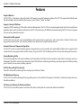
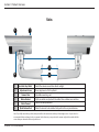
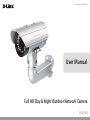
Version 2.01 | 05/27/2014 User Manual Full HD Day & Night Outdoor Network Camera DCS-7413 Preface D-Link reserves the right to revise this publication and to make changes in the content hereof without obligation to notify any person or organization of such revisions or changes. Information in this document may become obsolete as our services and websites develop and change. Manual Revisions Revision Date Description 1.0 July 10, 2012 1.1 September 17, 2013 DCS‑7413 Revision A2 2.0 September 25, 2013 DCS‑7413 Revision B1 with firmware version 2.00 2.01 May 27, 2014 DCS‑7413 Revision B1 with firmware version 2.00 DCS‑7413 Revision A1 with firmware version 1.00 Trademarks D-Link and the D-Link logo are trademarks or registered trademarks of D-Link Corporation or its subsidiaries in the United States or other countries. All other company or product names mentioned herein are trademarks or registered trademarks of their respective companies. Copyright © 2014 D-Link Corporation. All rights reserved. This publication may not be reproduced, in whole or in part, without prior expressed written permission from D-Link Corporation. D-Link DCS-7413 User Manual 2 Table of Contents Product Overview.......................................................................... 4 Package Contents.................................................................. 4 Introduction............................................................................. 5 System Requirements.......................................................... 5 Features..................................................................................... 6 Hardware Overview.............................................................. 7 Front....................................................................................... 7 Sides....................................................................................... 8 Cable Harness..................................................................... 9 Internal................................................................................10 Assembly and Installation........................................................11 Installing an SD Card..........................................................11 Mounting the Camera........................................................13 Attaching the Camera to the Wire-in Bracket........14 Orienting the Camera.....................................................16 Deploying the Camera...................................................17 Camera Installation Wizard..............................................20 Connection with 12 V DC Power Adapter...............20 Connection with 24 V AC Power Wiring...................21 Connection with Power over Ethernet.....................22 Software Installation.......................................................23 Configuration................................................................................26 Using the Configuration Interface.................................26 Live Video...............................................................................27 Setup........................................................................................29 Setup Wizard.....................................................................29 D-Link DCS-7413 User Manual Network Setup..................................................................35 Dynamic DNS....................................................................38 Image Setup......................................................................39 Audio and Video...............................................................41 Preset....................................................................................43 Motion Detection............................................................45 Time and Date...................................................................46 Event Setup........................................................................47 SD Card................................................................................55 Advanced................................................................................56 Digital Input/Output.......................................................56 ICR and IR............................................................................57 HTTPS...................................................................................58 Access List...........................................................................59 Maintenance..........................................................................60 Device Management......................................................60 System.................................................................................61 Firmware Upgrade...........................................................62 Status.......................................................................................63 Device Info.........................................................................63 Logs......................................................................................64 Help......................................................................................65 DI/DO Specifications..................................................................66 Technical Specifications............................................................67 3 Section 1: Product Overview Product Overview Package Contents DCS‑7413 Full HD Day & Night Outdoor Network Camera Wire in Bracket and Mounting Shoe CAT5 Ethernet cable Power adapter CD-ROM with User Manual and software Mounting Plate Alignment Sticker and Fixings Kit Quick Installation Guide If any of the above items are missing, please contact your reseller. Note: Using a power supply with a different voltage than the one included with your product will cause damage and void the warranty for this product. D-Link DCS-7413 User Manual 4 Section 1: Product Overview Introduction Congratulations on your purchase of the DCS‑7413 Full HD Day & Night Outdoor Network Camera. The DCS‑7413 is a professional surveillance and security solution for small, medium, and large enterprises alike. The DCS-7413 uses a 2 megapixel progressive scan CMOS sensor; the professional sensor results in low noise and high sensitivity capabilities ideal for surveillance applications. The DCS‑7413 is a complete system built with an ARM SoC CPU that incorporates a web server, allowing it to transmit excellent real-time Full HD resolution video quality for security and outdoor surveillance. The DCS‑7413 can be accessed remotely, controlled and configured from any PC/Notebook over your local network or through the Internet via a web browser. The simple installation and intuitive web-based interface offer easy configuration across the full range of its advanced feature set, including granular control over multiple video streams with different configurations and multicast video/audio streams which helps you manage your network load. The DCS‑7413 has an IP68 certified weatherproof housing designed for both indoor and outdoor applications. The built-in removable IR-cut filter and IR LEDs give the DCS-7413 the capability to view up to 30M at night. The DCS-7413 also incorporates Power over Ethernet (PoE), allowing it to be easily installed in a variety of locations without the need for supplemental power cabling. The combination of IP68 housing, IR-Cut Filter, IR LEDs and PoE make the DCS-7413 an ideal solution for a dependable and cost-effective 24 hour surveillance solution with an easy clutter-free installation. System Requirements • • • • • • Computer with Microsoft Windows® 8, 7, Vista®, or XP (for CD-ROM Setup Wizard), Mac OS or Linux PC with 1.3GHz or above; at least 128MB RAM Internet Explorer 7 or above , Firefox 3.5 or above, Safari 4 and Chrome 8.0 or above Existing 10/100 Ethernet-based network An SD memory card (optional) is required for recording to onboard storage. SDHC Class 6 or above is recommended. SDXC Class 10 or above is recommended. Broadband Internet connection D-Link DCS-7413 User Manual 5 Section 1: Product Overview Features Simple to Maintain The DCS‑7413 is a stand-alone system with a built-in CPU, requiring no special hardware or software. The DCS‑7413 supports both ActiveX mode for Internet Explorer and Java mode for other browsers such as Chrome®, Firefox® and Safari®. Supports a Variety of Platforms Supporting TCP/IP networking, HTTP, and other Internet related protocols. The DCS‑7413 can also be integrated easily into other Internet/Intranet applications because of its standards-based features. The DCS‑7413 works with any 10/100 Ethernet network, making the DCS‑7413 easy to integrate into your existing network environment. Advanced Event Management The DCS‑7413 can be set up to send e-mail notifications with snapshots when an event occurs, such as when motion is detected. Events can be triggered from several sources, such as motion detection, timer based events or digital input based events. Automatic Thermostat Temperature Regulation The DCS-7413 monitors and automatically regulates its temperature to ensure it can perform at its optimal ability. It balances fan use against a built in heater based on a range of preset thermostatic settings. This gives the DCS-7413 the ability to perform in the most demanding of environments. Remote Monitoring Utility The D-ViewCam application adds enhanced features and functionality for the Network Camera and allows administrators to configure and access the Network Camera from a remote site via Intranet or Internet. Other features include image monitoring, recording images to a hard drive, viewing up to 32 cameras on one screen, and taking snapshots. IR LED for Day and Night Functionality The built-in infrared LEDs enables night time viewing of up to 30 meters (98 feet). IP68 Weatherproof Housing The DCS‑7413 uses an IP68 weatherproof housing, allowing you to rest assured that in the toughest of conditions, it will continue to provide roundthe-clock surveillance. PoE (Power over Ethernet) for Flexible Installation The DCS‑7413 can draw all the power it needs from a PoE switch or PoE injector for a simple and clutter-free installation. D-Link DCS-7413 User Manual 6 Section 1: Product Overview Hardware Overview Front 3 4 1 2 5 1 Camera Lens 2 ICR Sensor 3 IR LEDs 4 Power/Status LED 5 Weatherproof Casing D-Link DCS-7413 User Manual Fixed lens to record video of the surrounding area The IR-Cut Removable sensor measures the lighting conditions and switches between color and infrared accordingly Infrared LEDs illuminate the camera's field of view at night Indicates the camera's current status The camera is housed in an IP68 certified weatherproof casing, which protects it against rain and dust. 7 Section 1: Product Overview Sides 2 1 3 4 6 5 1 Adjustable Top Shield 2 Adjustment Screw 3 Camera Shoe 4 Wire in Bracket Tightly assembles and protects the cables from outdoor wear and tear. 5 Cable Channel Channel for cable placement. 6 Quick Release Rod Shields the camera sensor from direct sunlight. Allows adjustment of the Top Shield. Adjustable mounting seat. Allows the camera to be swiveled into position for easy maintenance. Note: If you fully extend the top shield, it may be visible in the camera view in the top left and right corners of your video. It is recommended that you always check your camera’s video whenever you reposition the camera or adjust the weather shield to ensure that your camera has the best possible view. D-Link DCS-7413 User Manual 8 Section 1: Product Overview Cable Harness 8 7 1 Power Connector 2 Audio In (Red) 3 Audio Out (Green) 4 BNC Connector 5 Reset Button 6 24 V Power Connector 7 DI/DO Connector 8 Ethernet Jack D-Link DCS-7413 User Manual 6 5 4 3 2 1 Power connector for the provided 12V DC power adapter. Connects to a microphone. Connects to a speaker. The BNC connector is recommended for use with handheld monitors to check the Field of View during installation. Press and hold the recessed button for 10 seconds to reset the camera. Connects to 24 V AC power supply. I/O connectors for external devices. 12V DC output. Connects to an RJ45 Ethernet port. Can be replaced with a PoE cable to provide power to the camera. 9 Section 1: Product Overview Internal 1 1 SD Card Slot Insert an SD card for Local storage for storing recorded image and video Note: For step-by-step instruction on how to insert an SD card please skip to "Installing an SD Card" on page 11. D-Link DCS-7413 User Manual 10 Section 2: Assembly and Installation Assembly and Installation Installing an SD Card Step 1 Place the camera face down on a non-slip flat surface. Step 2 Remove the adjustable top shield by removing the two retaining screws. 2 Step 3 Remove the base of the camera by holding the camera firmly and rotating the base in a counter clockwise direction. 3 D-Link DCS-7413 User Manual 11 Section 2: Assembly and Installation Step 4 Insert your SD memory card into the slot with the notch oriented to the fore of the camera. 4 Step 5 Replace the base of the camera by holding the camera firmly and rotating the base in a clockwise direction ensuring a tight fit. Note: Users are advised to ensure that the weatherproof seals are secured firmly in place. 5 D-Link DCS-7413 User Manual 12 Section 2: Assembly and Installation Mounting the Camera The DCS-7413 is suitable for mounting to a wall using the camera shoe and wire-in bracket provided. Step 1 Straighten the two sets of cables from the camera side by side. Step 2 Pass individual cables into the wire-in bracket ensuring the head of each has fully passed through the bend. Step 3 Once all the cables are in the wire-in bracket push the cable until you are able to pull them through the base of the bracket. Step 4 Attach the camera bracket to the wire-in bracket following the steps outlined in "Attaching the Camera to the Wire-in Bracket" on page 14. 1 2 3 D-Link DCS-7413 User Manual 13 Section 2: Assembly and Installation Attaching the Camera to the Wire-in Bracket Note: Before attaching the camera to the wire-in bracket, ensure the camera shoe is oriented correctly for its final position. For instructions on how to orient the camera shoe skip to "Orienting the Camera" on page 16. Step 1 Using the two screws provided attach the quick release retention clip to the underside of the camera. D-Link DCS-7413 User Manual 14 Section 2: Assembly and Installation Step 2 Push the quick release rod to reveal the attachment notches. Step 3 Slot the quick release retention clip over the quick release rod. Step 4 Allow the quick release rod to return. 3 2 Step 5 Using the Allen Wrench provided, tighten the two remaining fixing bolts. 5 D-Link DCS-7413 User Manual 15 Section 2: Assembly and Installation Orienting the Camera The DCS-7413 can be adjusted to ensure an optimal viewing position when mounted to a wall by following the steps outlined. Step 1 Using the Allen Wrench provided, loosen the adjusting bolts on both sides of the camera shoe. This will allow you to adjust the vertical orientation of the camera. Step 2 Firmly tighten the adjustment bolts on both sides of the camera shoe. Step 3 Using the Allen Wrench provided, loosen the adjusting bolts on both sides of the wire-in bracket. This will allow you to adjust the horizontal orientation of the camera. 1 3 Step 4 Firmly tighten the adjustment bolts on both sides of the wire-in bracket. D-Link DCS-7413 User Manual 16 Section 2: Assembly and Installation Deploying the Camera Note: Before deploying the camera to a fixed location, it is recommended that you take a photo from the desired location to ensure an adequate field-of-view. Step 1 Position the Alignment Sticker in the desired location making sure the Camera and Wire-in-Bracket have sufficient space. Use the dimension diagrams in "Dimensions" on page 69 for additional reference. Step 2 Use a 6mm drill bit to make required holes approximately 30mm deep. 1 Step 3 Remove the Alignment Sticker. Step 4 Insert wall anchors and affix the mounting plate using the screws provided. 4 D-Link DCS-7413 User Manual 17 Section 2: Assembly and Installation Step 5 Suspend the camera and wire-in bracket from the two lugs on the mounting plate. 5 Step 6 Fasten the camera firmly to the mounting plate using the screw provided ensuring clear passage for the cables through the cable channel or via the mounting plate cut-out. 5 6 D-Link DCS-7413 User Manual 6 18 Section 2: Assembly and Installation Note: To prevent the camera's wire connectors from being damaged by water or other elements: 1. When connecting the camera, the unsheathed part of the wire connectors must either be sealed or enclosed in a junction box. 2. The unsheathed part of the wire connectors should be positioned at a downward-facing angle when they extend out of the rear of the camera, not upward. The unsheathed part of the wire connectors must either be sealed or enclosed in a junction box. D-Link DCS-7413 User Manual 19 Section 2: Assembly and Installation Camera Installation Wizard Connection with 12 V DC Power Adapter Step 1 Connect the network camera to a hub via an Ethernet cable. Step 2 Connect the supplied power cable from the camera to a power outlet. 2 1 D-Link DCS-7413 User Manual 20 Section 2: Assembly and Installation Connection with 24 V AC Power Wiring Step 1 Connect the network camera to a hub via an Ethernet cable. Step 2 Connect the supplied power cable from the camera to a power source such as your building's emergency power. 2 1 D-Link DCS-7413 User Manual 21 Section 2: Assembly and Installation Connection with Power over Ethernet Step 1 If you are using a PoE hub, connect the IP camera to the hub via an Ethernet cable, which will provide transmission of both power and data over a single cable. 1 D-Link DCS-7413 User Manual 22 Section 2: Assembly and Installation Software Installation Step 1 Insert the Installation CD-ROM into your computer’s optical drive to start the autorun program. The CD-ROM will open the Camera Installation Wizard. The Setup Wizard will guide you through the installation process through to configuring your camera. Note: If the autorun program does not automatically start on your computer, go to Windows, click Start > Run. In the Run command box type D:\autorun.exe, where D: represents your CD-ROM drive. Step 2 Accept the End User Licence Agreement and follow the on screen prompts to install the Camera Installation Wizard. 3 Step 3 Select your camera from the list, then click Wizard. If you have multiple cameras, you can identify them by the MAC ID printed on the label on the back of your camera. D-Link DCS-7413 User Manual 23 Section 2: Assembly and Installation Step 4 By default the Admin ID is "admin" and the password is blank. It is recommended that you create and confirm a password for your device. Click Next to continue. Step 5 Select Static IP if your Internet Service Provider has provided you with connection settings, or if you wish to set a static address within your home network. Enter the correct configuration information and click Next to continue. Note: Select DHCP if you are unsure of which settings to choose. Click Next to continue. D-Link DCS-7413 User Manual 24 Section 2: Assembly and Installation Step 6 Confirm your camera login details and IP address details and click Restart. The LED on the front of the DCS‑7413 will blink, then turn solid green once it successfully connects to your network. Step 7 Your DCS‑7413 camera is now set up, Click Exit to exit the wizard and can skip to "Configuration" on page 26 for advanced configuration of your camera. D-Link DCS-7413 User Manual 25 Section 3: Configuration Configuration Using the Configuration Interface After completing the Camera Installation Wizard, you are ready to use your camera. The camera’s built-in Web configuration utility is designed to allow you to easily access and configure your DCS‑7413. At the end of the wizard, click Link, or enter the IP address of your camera into a web browser, such as Mozilla Firefox. To log in, use the User name admin and the password you created in the Installation Wizard. If you did not create a password, the default password is blank. After entering your password, click OK. Step 1 Click the Link button on the Wizard. 1 Step 2 Enter your credentials to access the configuration interface. 2 D-Link DCS-7413 User Manual 26 Section 3: Configuration Live Video This section shows your camera’s live video. You may select any of the available icons listed below to operate the camera. You may also select your language using the drop-down menu on the left side of the screen. You can zoom in and out on the live video image using your mouse. Right-click to zoom out or left-click to zoom in on the image. SD Status: This option displays the status of the SD card. If no SD card has been inserted, this screen will display the message "Card Invalid." IO Status: This option displays the status of your I/O device if a device has been connected. Digital Input Indicator Motion Trigger Indicator This indicator will change color when a digital input signal is detected. This indicator will change color when a trigger event occurs. Stop Note: The video motion feature for your camera must be enabled. When a recording is in progress, this indicator will change color. This control pad can be used to electronically pan, tilt, and zoom (ePTZ) within the camera's predefined view area, if one has been defined. Starts the automatic panning function. The ROI will pan from back and forth within the FOV Stops the camera ePTZ motion Preset Path Starts the camera's motion along the predefined path Recording Indicator Control Pad Auto Pan ePTZ Speed: You may select a value between 0 and 10. 0 is the slowest and 10 is the fastest. D-Link DCS-7413 User Manual 27 Section 3: Configuration Global View: This window indicates the total field of view (FOV) of the camera. The red box indicates the visible region of interest (ROI). Language: You may select the interface language using this menu. Video Profile 1 Record a Video Clip Video Profile 2 Set a Storage Folder Video Profile 3 Listen/Stop Audio In (from microphone) Full screen mode Start/Stop Audio Out (to speaker) Taking a Snapshot Start/Stop Digital Output Go To: If any presets have been defined, selecting a preset from this list will (Preset List) display it. D-Link DCS-7413 User Manual 28 Section 3: Configuration Setup Setup Wizard To configure your Network Camera, click Internet Connection Setup Wizard. Alternatively, you may click Manual Internet Connection Setup to manually configure your Network Camera and skip to "Network Setup" on page 35. To quickly configure your Network Camera’s motion detection settings, click Motion Detection Setup Wizard. If you want to enter your settings without running the wizard, click Manual Motion Detection Setup and skip to"Motion Detection" on page 45. D-Link DCS-7413 User Manual 29 Section 3: Configuration Internet Connection Setup Wizard This wizard will guide you through a step-by-step process to configure your new D-Link Camera and connect the camera to the internet. Click Next to continue. Note: Select DHCP if you are unsure of which settings to choose. Click Next to continue. D-Link DCS-7413 User Manual 30 Section 3: Configuration Select Static IP if your Internet Service Provider has provided you with connection settings, or if you wish to set a static address within your home network. Enter the correct configuration information and click Next to continue. If you are using PPPoE, select Enable PPPoE and enter your user name and password, otherwise click Next to continue. If you have a Dynamic DNS account and would like the camera to update your IP address automatically, Select Enable DDNS and enter your host information. Click Next to continue. Enter a name for your camera and click Next to continue. D-Link DCS-7413 User Manual 31 Section 3: Configuration Configure the correct time to ensure that all events will be triggered as scheduled. Click Next to continue. Confirm the settings are correct and click Apply to save them. The settings will be saved to the DCS-7413 and the camera will restart. D-Link DCS-7413 User Manual 32 Section 3: Configuration Motion Detection Setup Wizard This wizard will guide you through a step-by-step process to configure your camera's motion detection functions. Click Next to continue. Step 1 This step will allow you to enable or disable motion detection, specify the detection sensitivity, and adjust the camera’s ability to detect movement. You may specify whether the camera should capture a snapshot or a video clip when motion is detected. Please see the Motion Detection section on "Motion Detection" on page 45 for information about how to configure motion detection. Step 2 This step allows you to enable motion detection based on a customized schedule. Specify the day and hours. You may also choose to always record whenever motion is detected. D-Link DCS-7413 User Manual 33 Section 3: Configuration Step 3 This step allows you to specify how you will receive event notifications from your camera. You may choose not to receive notifications, or to receive notifications via e-mail or FTP. Please enter the relevant information for your e-mail or FTP account. Click Next to continue. Step 4 You have completed the Motion Detection Wizard. Please verify your settings and click Apply to save them. Please wait a few moments while the camera saves your settings and restarts. D-Link DCS-7413 User Manual 34 Section 3: Configuration Network Setup Use this section to configure the network connections for your camera. All relevant information must be entered accurately. After making any changes, click the Save Settings button to save your changes. LAN Settings: This section lets you configure settings for your local area network. DHCP: Select this connection if you have a DHCP server running on your network and would like your camera to obtain an IP address automatically. If you choose DHCP, you do not need to fill out the IP address settings. Static IP Client: You may obtain a static or fixed IP address and other network information from your network administrator for your camera. A static IP address may simplify access to your camera in the future. IP Address: Enter the fixed IP address in this field. Subnet Mask: This number is used to determine if the destination is in the same subnet. The default value is 255.255.255.0. Default Gateway: The gateway used to forward frames to destinations in a different subnet. Invalid gateway settings may cause the failure of transmissions to a different subnet. Primary DNS: The primary domain name server translates names to IP addresses. Secondary DNS: The secondary DNS acts as a backup to the primary DNS. D-Link DCS-7413 User Manual 35 Section 3: Configuration Enable UPnP Presentation: Enabling this setting allows your camera to be configured as a UPnP device on your network. Enable UPnP Port Forwarding: Enabling this setting allows the camera to add port forwarding entries into the router automatically on a UPnP capable network. Enable PPPoE: Enable this setting if your network uses PPPoE. User Name / Password: Enter the username and password for your PPPoE account. Re-enter your password in the Confirm Password field. You may obtain this information from your ISP. HTTP Port: The default port number is 80. Access Name for Stream 1~3: The default name is video#.mjpg, where # is the number of the stream. HTTPS Port: You may use a PC with a secure browser to connect to the HTTPS port of the camera. The default port number is 443. Authentication: Choose to enable or disable RTSP digest encryption. Digest encryption uses MD5 hashes. RTSP Port: The port number that you use for RTSP streaming to mobile devices, such as mobile phones or PDAs. The default port number is 554. You may specify the address of a particular stream. For instance, live1.sdp can be accessed at rtsp://x.x.x.x/video1.sdp where the x.x.x.x represents the ip address of your camera. D-Link DCS-7413 User Manual 36 Section 3: Configuration Enable CoS: Enabling the Class of Service setting implements a best-effort policy without making any bandwidth reservations. Enable QoS: Enabling QoS allows you to specify a traffic priority policy to ensure a consistent Quality of Service during busy periods. If the Network Camera is connected to a router that itself implements QoS, the router's settings will override the QoS settings of the camera. Enable IPv6: Enable the IPv6 setting to use the IPv6 protocol. Enabling the option allows you to manually set up the address, specify an optional IP address, specify an optional router and an optional primary DNS. Enable Multicast for stream The DCS‑7413 allows you to multicast each of the available streams via group address and specify the TTL value for each stream. Enter the port and TTL settings you wish to use if you do not want to use the defaults. D-Link DCS-7413 User Manual 37 Section 3: Configuration Dynamic DNS DDNS (Dynamic Domain Name Server) will hold a DNS host name and synchronize the public IP address of the modem when it has been modified. A user name and password are required when using the DDNS service. After making any changes, click the Save Settings button to save your changes. Enable DDNS: Select this checkbox to enable the DDNS function. Server Address: Select your Dynamic DNS provider from the pull down menu or enter the server address manually. Host Name: Enter the host name of the DDNS server. User Name: Enter the user name or e-mail used to connect to your DDNS account. Password: Enter the password used to connect to your DDNS server account. Timeout: Enter the DNS timeout values you wish to use. Status: Indicates the connection status, which is automatically determined by the system. D-Link DCS-7413 User Manual 38 Section 3: Configuration Image Setup In this section, you may configure the video image settings for your camera. A preview of the image will be shown in Live Video. Enable Privacy Mask: The Privacy Mask setting allows you to specify up to 3 rectangular areas on the camera's image to be blocked/ excluded from recordings and snapshots. You may click and drag the mouse cursor over the camera image to draw a mask area. Right clicking on the camera image brings up the following menu options: Disable All: Disables all mask areas Enable All: Enables all mask areas Reset All: Clears all mask areas. Mirror: This will mirror the image horizontally. Flip: This will flip the image vertically. When turning Flip on, you may want to consider turning Mirror on as well. Power Line: Select the frequency used by your power lines to avoid interference or distortion. White Balance: Use the drop-down box to change white balance settings to help balance colors for different environments. You can choose from Auto, Outdoor, Indoor, Fluorescent, and Push Hold. Exposure Mode: Changes the exposure mode. Use the drop-down box to set the camera for Indoor, Outdoor, or Night D-Link DCS-7413 User Manual 39 Section 3: Configuration environments, or to Moving to capture moving objects. The Low Noise option will focus on creating a highquality picture without noise. You can also create 3 different custom exposure modes. The Max Gain setting will allow you to control the maximum amount of gain to apply to brighten the picture. Denoise: This setting controls the amount of noise reduction that will be applied to the picture. Brightness: Adjust this setting to compensate for backlit subjects. Contrast: Adjust this setting to alter the color intensity/strength. Saturation: This setting controls the amount of coloration, from grayscale to fully saturated. Sharpness: Specify a value from 0 to 8 to specify how much sharpening to apply to the image. Reset Default: Click this button to reset the image to factory default settings. D-Link DCS-7413 User Manual 40 Section 3: Configuration Audio and Video You may configure up to 3 video profiles with different settings for your camera. Hence, you may set up different profiles for your computer and mobile display. In addition, you may also configure the two-way audio settings for your camera. After making any changes, click the Save Settings button to save your changes. Aspect ratio: Set the aspect ratio of the video to 4:3 standard or 16:9 widescreen. Mode: Set the video codec to be used to JPEG, MPEG-4, or H.264. Frame size / View window area: Frame size determines the total capture resolution, and View window area determines the Live Video viewing window size. If the Frame size is larger than the Live Video size, you can use the ePTZ controls to look around. 16:9 1920 x 1080, 1280 x 720, 800 x 450, 640 x 360, 480 x 270, 320 x 176, 176 x 144 up to 30 fps 4:3 1440 x 1080, 1280 x 960, 1024 x 768, 800 x 600, 640 x 480, 320 x 240, 176 x 144 up to 30 fps Note: If your View window area is the same as your Frame size, you will not be able to use the ePTZ function. Maximum frame rate: A higher frame rate provides smoother motion for videos, and requires more bandwidth. Lower frame rates will result in stuttering motion, and requires less bandwidth. D-Link DCS-7413 User Manual 41 Section 3: Configuration This limits the maximum frame rate, which can be Video Quality: combined with the "Fixed quality" option to optimize the bandwidth utilization and video quality. If fixed bandwidth utilization is desired regardless of the video quality, choose "Constant bit rate" and select the desired bandwidth. The bps will affect the bit rate of the video recorded Constant bit rate: by the camera. Higher bit rates result in higher video quality. Select the image quality level for the camera to try to Fixed quality: maintain. High quality levels will result in increased bit rates. Audio in off: Selecting this checkbox will mute incoming audio. This setting controls the amount of gain applied to Audio in gain level: incoming audio to increase its volume. Audio out off: Selecting this checkbox will mute outgoing audio. This setting controls the amount of gain applied to Audio out volume level: outgoing audio to increase its volume. D-Link DCS-7413 User Manual 42 Section 3: Configuration Preset This screen allows you to set preset points for the ePTZ function of the camera, which allows you to look around the camera's viewable area by using a zoomed view. Presets allow you to quickly go to and view a specific part of the area your camera is covering, and you can create preset sequences, which will automatically change the camera's view between the different presets according to a defined order and timing you can set. Note: If your View window area is the same as your Frame size, you will not be able to use the ePTZ function. Video Profile: This selects which video profile to use. ePTZ Speed: You may select a value between 0 and 10. 0 is the slowest and 10 is the fastest. Arrow Buttons and Home Button: Use these buttons to move to a specific part of the viewing area, which you can then set as a preset. Click the Home button to return to the center of the viewing area. Input Preset Name: Enter the name of the preset you want to create, then click the Add button to make a new preset. If an existing preset has been selected from the Preset List, you can change its name by typing in a new name, then clicking the Rename button. Preset List: Click this drop-down box to see a list of all the presets that have been created. You can select one, then click the GoTo button to change the displayed camera view to the preset. Clicking the Remove button will delete the currently selected preset. Preset Sequence: This section allows you to create a preset sequence, which automatically moves the camera's view between a set of preset views. D-Link DCS-7413 User Manual 43 Section 3: Configuration Preset List: To add a preset to the sequence, select it from the dropdown box at the bottom of this window, set the Dwell time to determine how long the camera view will stay at that preset, then click the Add button. The preset name will appear in the list, followed by the dwell time to view that preset for. You can rearrange your presets in the sequence by selecting a preset in the sequence, then clicking the arrow buttons to move it higher or lower in the current sequence. Clicking the trash can button will remove the currently selected preset from the sequence. If you want to change the dwell time for a preset, select it from the list, enter a new dwell time, then click the Update button. D-Link DCS-7413 User Manual 44 Section 3: Configuration Motion Detection Enabling Video Motion will allow your camera to use the motion detection feature. You may draw a finite motion area that will be used for monitoring. After making any changes, click the Save Settings button to save your changes. Enable Video Motion: Select this box to enable the motion detection feature of your camera. Sensitivity: Specifies the measurable difference between two sequential images that would indicate motion. Please enter a value between 0 and 100. Percentage: Specifies the amount of motion in the window being monitored that is required to initiate an alert. If this is set to 100%, motion is detected within the whole window will trigger a snapshot. Draw Motion Area: Draw the motion detection area by dragging your mouse in the window (indicated by the red square). Erase Motion Area: To erase a motion detection area, simply click on the red square that you wish to remove. Right clicking on the camera image brings up the following menu options: Select All: Draws a motion detection area over the entire screen. Clear All: Clears any motion detection areas that have been drawn. Restore: Restores the previously specified motion detection areas. D-Link DCS-7413 User Manual 45 Section 3: Configuration Time and Date This section allows you to automatically or manually configure, update, and maintain the internal system clock for your camera. After making any changes, click the Save Settings button to save your changes. Time Zone: Select your time zone from the drop-down menu. Enable Daylight Saving: Select this to enable Daylight Saving Time. Auto Daylight Saving: Select this option to allow your camera to configure the Daylight Saving settings automatically. Set Date and Time Manually: Selecting this option allows you to configure the Daylight Saving date and time manually. Offset: Sets the amount of time to be added or removed when Daylight Saving is enabled. Synchronize with NTP Server: Enable this feature to obtain time automatically from an NTP server. NTP Server: Network Time Protocol (NTP) synchronizes the DCS‑7413 with an Internet time server. Choose the one that is closest to your location. Set the Date and Time Manually: This option allows you to set the time and date manually. Copy Your Computer's Time This will synchronize the time information from your PC. Settings: D-Link DCS-7413 User Manual 46 Section 3: Configuration Event Setup In a typical application, when motion is detected, the DCS‑7413 sends images to a FTP server or via e-mail as notifications. As shown in the illustration below, an event can be triggered by many sources, such as motion detection. When an event is triggered, a specified action will be performed. You can configure the Network Camera to send snapshots or videos to your e-mail address or FTP site. Action Event Condition ex. Motion detection, Periodically, Digital input, System reboot Media (what to send) ex. Snapshot, Video Clips Server (where to send) ex. Email, FTP To start plotting an event, it is suggested to configure server and media columns first so that the Network Camera will know what action shall be performed when a trigger is activated. D-Link DCS-7413 User Manual 47 Section 3: Configuration The Event Setup page includes 4 different sections. • Event • Server • Media • Recording 1. To add a new item - "event, server or media," click Add. A screen will appear and allow you to update the fields accordingly. 2. To delete the selected item from the pull-down menu of event, server or media, click Delete. 3. Click on the item name to pop up a window for modifying. D-Link DCS-7413 User Manual 48 Section 3: Configuration Add Server You can configure up to 5 servers to save snapshots and/or video to. After making any changes, click the Save Settings button to save your changes. Server Name: Enter the unique name of your server. E-mail: Enter the configuration for the target e-mail server account. FTP: Enter the configuration for the target FTP server account. Network Storage: Specify a network storage device. Only one network storage device is supported. SD Card: Use the camera's onboard SD card storage. D-Link DCS-7413 User Manual 49 Section 3: Configuration Add Media There are three types of media, Snapshot, Video Clip, and System Log. After making any changes, click the Save Settings button to save your changes. Media Name: Enter a unique name for media type you want to create. Snapshot: Select this option to set the media type to snapshots. Source: Set the video profile to use as the media source. Refer to Audio and Video on "Audio and Video" on page 41 for more information on video profiles. Send pre-event image(s) [0~4]: Set the number of pre-event images to take. Pre-event images are images taken before the main event snapshot is taken. Send post-event image(s) [0~7]: Set the number of post-event images to take. Post-event images are images taken after the main event snapshot is taken. You can set up to 7 post-event images to be taken. For example: If both the Send pre-event images and Send post-event images are set to four, a total of 9 images are generated after a trigger is activated. 1 pic. 2 pic. 3 pic. 4 pic. 5 pic. 6 pic. 7 pic. 8 pic. 9 pic. The moment the trigger is activated. D-Link DCS-7413 User Manual 50 Section 3: Configuration File name prefix: The prefix name will be added on the file name. SNAPSHOTS20080104_100341 File name prefix Date and time suffix The format is: YYYYMMDD_HHMMSS Add date and time suffix to file Check this to add timing information as file name suffix. name: Video clip: Select this option to set the media type to video clips. Source: Set the video profile to use as the media source. Refer to "Audio and Video" on page 41 for more information on video profiles. Pre-event recording: This sets how many seconds to record before the main event video clip starts. You can record up to 4 seconds of pre-event video. Maximum duration: Set the maximum length of video to record for your video clips. Maximum file size: Set the maximum file size to record for your video clips. System log: Select this option to set the media type to system logs. This will save the event to the camera system log, but will not record any snapshots or video. D-Link DCS-7413 User Manual 51 Section 3: Configuration Add Event Create and schedule up to 3 events with their own settings here. After making any changes, click the Save Settings button to save your changes. Event name: Enter a name for the event. Enable this event: Select this box to activate this event. Priority: Set the priority for this event. The event with higher priority will be executed first. Delay: Select the delay time before checking the next event. It is being used for both events of motion detection and digital input trigger. Trigger: Specify the input type that triggers the event. Video Motion Detection: Motion is detected during live video monitoring. Select the windows that need to be monitored. Periodic: The event is triggered in specified intervals. The trigger interval unit is in minutes. Digital Input: The external trigger input to the camera. System Boot: Triggers an event when the system boots up. Network Lost: Triggers an event when the network connection is lost. Time: Select Always or enter the time interval. Server: Specify the location where the event information should be saved to. D-Link DCS-7413 User Manual 52 Section 3: Configuration Add Recording Here you can configure and schedule the recording settings. After making any changes, click the Save Settings button to save your changes. Recording entry name: The unique name of the entry. Enable this recording: Select this to enable the recording function. Priority: Set the priority for this entry. The entry with a higher priority value will be executed first. Source: The source of the stream. Recording schedule: Scheduling the recording entry. Recording settings: Configuring the setting for the recording. Destination: Select the folder where the recording file will be stored. Total cycling recording size: Please input a HDD volume between 1MB and 2TB for recording space. The recording data will replace the oldest record when the total recording size exceeds this value. For example, if each recording file is 6MB, and the total cyclical recording size is 600MB, then the camera will record 100 files in the specified location (folder) and then will delete the oldest file and create new file for cyclical recording. Please note that if the free HDD space is not enough, the recording will stop. Before you set up this option please make sure your HDD has enough space, and it is better to not save other files in the same folder as recording files. D-Link DCS-7413 User Manual 53 Section 3: Configuration Size of each file for recording: If this is selected, files will be separated based on the file size you specify. Time of each file for recording: If this is selected, files will be separated based on the maximum length you specify. File Name Prefix: The prefix name will be added on the file name of the recording file(s). D-Link DCS-7413 User Manual 54 Section 3: Configuration SD Card Here you may browse and manage the recorded files which are stored on the SD card. Format SD Card: Click this icon to automatically format the SD card and create "picture" & "video" folders. View Recorded Picture: If the picture files are stored on the SD card, click on the picture folder and choose the picture file you would like to view. Playback Recorded Video: If video files are stored on the SD card, click on the video folder and choose the video file you would like to view. Refresh: Reloads the file and folder information from the SD card. D-Link DCS-7413 User Manual 55 Section 3: Configuration Advanced Digital Input/Output This screen allows you to control the behavior of digital input and digital output devices. The I/O connector provides the physical interface for digital output (DO) and digital input (DI) that is used for connecting a variety of external alarm devices such as IR-Sensors and alarm relays. The digital input is used for connecting external alarm devices and once triggered images will be taken and e-mailed. After making any changes, click the Save Settings button to save your changes. Select D/I or D/O Mode: The camera will send a signal when an event is triggered, depending upon the type of device connected to the DI circuit. N.C. stands for Normally Closed. This means that the normal state of the circuit is closed. Therefore events are triggered when the device status changes to "Open." N.O. stands for Normally Open. This means that the normal state of the circuit is open. Therefore events are triggered when the device status changes to "Closed." LED: You may specify whether or not to illuminate the status LED on the camera. Video Output: Enable/ disable the BNC terminal TV output signal. D-Link DCS-7413 User Manual 56 Section 3: Configuration ICR and IR Here you can configure the ICR and IR settings. An IR(Infrared) Cut-Removable(ICR) filter can be disengaged for increased sensitivity in low light environments. Automatic: The Day/Night mode is set automatically. Generally, the camera uses Day mode and switches to Night mode when needed. Day Mode: Day mode enables the IR Cut Filter. Night Mode: Night mode disables the IR Cut Filter. Schedule Mode: Set up the Day/Night mode using a schedule. The camera will enter Day mode at the starting time and return to Night mode at the ending time. IR Light Control: The camera can enable or disable the IR (infrared) light according to your preferences. This setting provides additional controls depending on your specific application. Off: The IR light will always be off. On: The IR light will always be on. Sync: The IR light will turn on when the ICR sensor is on. Schedule: The IR light will turn on or off according to the schedule that you specify below. D-Link DCS-7413 User Manual 57 Section 3: Configuration HTTPS This page allows you to install and activate an HTTPS certificate for secure access to your camera. After making any changes, click the Save Settings button to save your changes. Enable HTTPS Secure Connection: Enable the HTTPS service. Create Certificate Method: Choose the way the certificate should be created. Three options are available: Create a self-signed certificate automatically Create a self-signed certificate manually Create a certificate request and install Status: Displays the status of the certificate. Note: The certificate cannot be removed while the HTTPS is still enabled. To remove the certificate, you must first uncheck Enable HTTPS secure connection. D-Link DCS-7413 User Manual 58 Section 3: Configuration Access List Here you can set access permissions for users to view your DCS‑7413. Allow list: The list of IP addresses that have the access right to the camera. Start IP address: The starting IP Address of the devices (such as a computer) that have permission to access the video of the camera. Click Add to save the changes made. Note: A total of seven lists can be configured for both columns. End IP address: The ending IP Address of the devices (such as a computer) that have permission to access the video of the camera. Delete allow list: Remove the customized setting from the Allow List. Deny list: The list of IP addresses that have no access rights to the camera. Delete deny list: Remove the customized setting from the Delete List. For example: When the range of the Allowed List is set from 1.1.1.0 to 192.255.255.255 and the range of the Denied List is set from 1.1.1.0 to 170.255.255.255. Only users with IPs located between 171.0.0.0 and 192.255.255.255 can access the Network Camera. D-Link DCS-7413 User Manual Alowed List Denied List 59 Section 3: Configuration Maintenance Device Management You may modify the name and administrator’s password of your camera, as well as add and manage the user accounts for accessing the camera. You may also use this section to create a unique name and configure the OSD settings for your camera. Admin Password Setting: Set a new password for the administrator’s account. Add User Account: Add new user account. User Name: The user name for the new account. Password: The password for the new account. User List: All the existing user accounts will be displayed here. You may delete accounts included in the list, but you may want to reserve at least one as a guest account. Camera Name: Create a unique name for your camera that will be added to the file name prefix when creating a snapshot or a video clip. Enable OSD: Select this option to enable the On-Screen Display feature for your camera. Label: Enter a label for the camera, which will be shown on the OSD when it is enabled. Show Time: Select this option to enable the time-stamp display on the video screen. D-Link DCS-7413 User Manual 60 Section 3: Configuration System In this section, you may backup, restore and reset the camera configuration, or reboot the camera. Save To Local Hard Drive: You may save your current camera configuration as a file on your computer. Load From Local Hard Drive: Locate a pre-saved configuration by clicking Browse and then restore the pre-defined settings to your camera by clicking Load Configuration. Restore to Factory Default: You may reset your camera and restore the factory settings by clicking Restore Factory Defaults. Reboot Device: This will restart your camera. Schedule Reboot: If you want your camera to reboot on a regular schedule, check the Schedule Reboot checkbox, then select the days and time you want the camera to reboot on. D-Link DCS-7413 User Manual 61 Section 3: Configuration Firmware Upgrade The camera's current firmware version will be displayed on this screen. You may visit the D-Link Support Website to check for the latest available firmware version. To upgrade the firmware on your DCS‑7413, please download and save the latest firmware version from the D-Link Support Page to your local hard drive. Locate the file on your local hard drive by clicking the Browse button. Select the file and click the Upload button to start upgrading the firmware. Current Firmware Version: Displays the detected firmware version. Current Product Name: Displays the camera model name. File Path: Locate the file (upgraded firmware) on your hard drive by clicking Browse. Upload: Uploads the new firmware to your camera. D-Link DCS-7413 User Manual 62 Section 3: Configuration Status Device Info This page displays detailed information about your device and network connection. D-Link DCS-7413 User Manual 63 Section 3: Configuration Logs This page displays the log information of your camera. You may download the information by clicking Download. You may also click Clear to delete the saved log information. D-Link DCS-7413 User Manual 64 Section 3: Configuration Help This page provides helpful information regarding camera operation. D-Link DCS-7413 User Manual 65 Appendix A: DI/DO Specifications DI/DO Specifications D-Link DCS-7413 User Manual 66 Appendix A: Technical Specifications Technical Specifications Camera Network Camera Hardware Profile 1/2.7” 2 Megapixel progressive CMOS sensor 30 meter IR illumination distance Minimum illumination: 0 lux with IR LED on Built-in Infrared-Cut Removable (ICR) Filter module 10x digital zoom Minimum object distance 0.84M Camera Housing IP-68 compliant weatherproof housing Wire-in bracket Image Features Configurable image size, quality, frame rate, and bit rate Time stamp and text overlays Configurable motion detection windows Configurable privacy mask zones Configurable shutter speed, brightness, saturation, contrast, and sharpness Video Compression Simultaneous H.264/MPEG-4/MJPEG format compression H.264/MPEG-4 multicast streaming JPEG for still images Video Resolution 16:9 - 1920 x 1080, 1280 x 720, 800 x 450, 640 x 360, 480 x 270, 320 x 176, 176 x 144 up to 30 fps 4:3 - 1440 x 1080, 1280 x 960, 1024 x 768, 800 x 600, 640 x 480, 320 x 240, 176 x 144 up to 30 fps Audio Support G.726 G.711 External Device Interface 10/100 BASE-TX Fast Ethernet port Supports 802.3af PoE SD/SDHC/SDXC (Max.64G) card slot Audio input/output DI/DO Connector 12V DC Output Network Protocols IPv6 IPv4 TCP/IP UDP ICMP DHCP client NTP client (D-Link) DNS client DDNS client (D-Link) SMTP client FTP client HTTP / HTTPS Samba client PPPoE UPnP port forwarding RTP / RTSP/ RTCP IP filtering QoS CoS Multicast IGMP ONVIF compliant Security Administrator and user group protection Password authentication HTTP and RTSP authentication D-Link DCS-7413 User Manual Focal length: 3.6 mm Aperture: F1.8 Angle of view: (H) 88° (V) 50.4° (D) 101° 67 Appendix A: Technical Specifications System System Management Requirements for Web Interface General Browser: Internet Explorer, Firefox, Chrome, Safari Event Management Motion detection Event notification and uploading of snapshots/video clips via e-mail or FTP Supports multiple SMTP and FTP servers Multiple event notifications Multiple recording methods for easy backup Remote Management Take snapshots/video clips and save to local hard drive Configuration interface accessible via web browser Mobile Support Windows 2000/XP/Vista/Windows 8/7/iPhone/iPad/Android D-ViewCam™ System Operating System: Microsoft Windows 8/7/Vista/XP Requirements Web Browser: Internet Explorer 7 or higher Protocol: Standard TCP/IP D-ViewCam™ Software Functions Remote management/control of up to 32 cameras Viewing of up to 32 cameras on one screen Supports all management functions provided in web interface Scheduled motion triggered, or manual recording options Weight 1920g (with bracket and sunshield) External Power Adapter Input: 100 to 240 V AC, 50/60 Hz Output: 12 V DC 1.25 A Power Consumption 12.3 +-5% Watt Temperature Operating: -40 to 50 °C (-40 to 122 °F) Storage: -20° to 70° C (-4° to 158° F) Humidity Operating: 20% to 80% non-condensing Storage: 5% to 95% non-condensing Certifications CE CE LVD FCC C-Tick D-Link DCS-7413 User Manual 68 Appendix A: Technical Specifications Dimensions • D-Link DCS-7413 User Manual 69