1
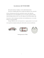
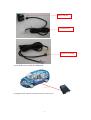
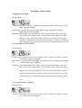
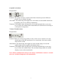
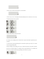
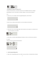
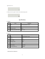
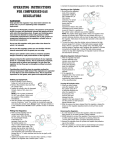
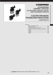
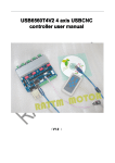
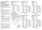
TPMS1309P05
User Manual
Suzhou Sate Auto Electronic Co., Ltd
www.sate.com.cn
Table of Contents
Introduction to the System ---------------------------------------------------------------------3
Installation of the System-----------------------------------------------------------------------4
Functions of the System------------------------------------------------------------------------7
Programming of the System Functions -----------------------------------------------------10
Specifications-----------------------------------------------------------------------------------14
2
Introduction to S&T TPMS1309P05
The system consists of 1 display, 1 receiver and 4 internal sensors.
The sensor is installed inside the tire to replace the original tire valve, senses the
pressure and temperature all the time and sends the pressure and temperature
information to the receiver through RF. The receiver can pick up and deal with the
data, then display the data on the screen. The display can issue different alarms if the
tire pressure is under an improper state based on the standard pressure so as to notify
the driver to treat the problem.
Through TPMS, the driver can keep the tire at a proper pressure so as to avoid
excess gasoline consumption and keep the vehicle under an easily controlled state.
Working principle of TPMS
3
Installation of the System
1. Group parts
Embeddable Display
Display
Sensor
Connection wire (power and signal)
2. Installation of Receiver and Display
2.1 Connect the wire cluster with the Display via the connector, as shown below
4
Back of display
Connection wire
Connector to display
2.2 Fix the Receiver inside the dashboard.
2.3 Plug the white connector of connection wire to the receiver.
5
Receiver
To connect with Receiver
2.4 Connect the power wires to the vehicle power supply according to correct polarity, as shown
below:
Black to negative
Blue for signal, to ignition switch
Red to negative
3. Installation of Sensor
Sensor
Nut
Valve Cap
6
Functions of the System
1. High Pressure Alarm
Display Mode:
Function: The system will issue a High Pressure Alarm when the tire pressure is 25%
higher than the standard.
Alarm mode: The alarm lamp, back light, High Pressure Warning Icon and the
Audible alarm turn on together.
Treatment: The audible alarm will stop after 10 seconds automatically or press any
key to silence the audible alarm. The red alarm lamp remains on and the
display reverts to the normal mode. Then the user should adopt a proper
measure to adjust the tire until the pressure reaches a proper level. The red
alarm lamp goes off only when the tire pressure returns to the normal level.
2. Low Pressure Level 1 Alarm
Display Mode:
Function: The system will issue a Low Pressure Level 1 Alarm when the tire pressure
is 12.5% lower than the standard.
Alarm mode: The alarm lamp, back light, Low Pressure Level 1 Warning Icon and the
Audible alarm turn on together.
Treatment: The audible alarm will stop after 10 seconds automatically or press any
key to silence the audible alarm. The red alarm lamp remains on and the
display reverts to the normal mode. Then the user should adopt a proper
measure to inflate the tire until the pressure reaches the proper level. The
red alarm lamp goes off only when the tire pressure returns to the normal
level.
3. Low Pressure Level 2 Alarm
Display Mode:
Function: The system will issue a Low Pressure Level 2 Alarm when the tire pressure
is 25 % lower than the standard.
7
Alarm mode: The alarm lamp, back light, Low Pressure Level 2 Warning Icon and the
Audible alarm turn on together.
Treatment: The audible alarm will stop after 10 seconds automatically or press any
key to silence the audible alarm. The red alarm lamp remains on and the
display reverts to the normal mode. Then the user should adopt a proper
measure to inflate the tire until the pressure reaches the proper level. The
red alarm lamp goes off only when the tire pressure returns to the normal
level.
4. Low Pressure Level 3 Alarm
Display Mode:
Function: The system will issue a Low Pressure Level 3 Alarm when the tire pressure
is 50 % lower than the standard.
Alarm mode: The alarm lamp, back light, Low Pressure Level 3 Warning Icon and the
Audible alarm turn on together.
Treatment: The audible alarm will stop after 10 seconds automatically or press any
key to silence the audible alarm. The red alarm lamp remains on and the
display reverts to the normal mode. Then the user should adopt a proper
measure to inflate the tire until the pressure reaches the standard level, or
use the spare tire and go to workshop to check the tire. The red alarm lamp
goes off only when the tire pressure returns to the standard level.
5. High Temperature Alarm
Display Mode:
Function: when the temperature inside a tire exceeds 75C, the system will issue a
High Temperature Alarm.
Alarm mode: The alarm lamp, back light, High Temperature Alarm Icon and the
Audible alarm turn on together.
Treatment: The audible alarm will stop after 10 seconds automatically or press any
key to silence the audible alarm. The red alarm lamp remains on and the
display reverts to the normal mode. Please slow down or pull over at a
safe place, then adopt a proper measure to cool down the tire. When the
tire temperature returns to normal level, the alarm lamp turns off
automatically.
8
6. Quick Leak Alarm
Display Mode:
Function: The system will issue a Quick Leak Alarm when the pressure difference
exceeds 1.4 psi within 8 seconds.
Alert Mode: The alarm lamp, back light, Fast Leak alarm icon and audible alarm turn
on together, the tire icon flashes continuously.
Treatment: The audible alarm will stop after 10 seconds automatically or press any
key to silence the audible alarm. Meanwhile slow down the car and stop at
a safe place for inspection.
7. Sensor Trouble Alarm
Display Mode:
Function: When one of the sensors fails to work, or the receiver cannot receive the
data because of the RF interference for a certain time, the sensor trouble
alarm will be issued.
Alarm Mode: The alarm lamp, back light, the sensor trouble alarm icon and the
audible alarm turn on together, the display shows “---”.
Treatment: The audible alarm will stop after 10 seconds automatically or press any
key to silence the audible alarm. The red alarm lamp remains on and the
display reverts to the normal mode.
Note: When communication between the Sensor and Monitor returns to normal
state, the red alarm lamp turns off automatically.
9
IV Programming of System Functions
1. Buttons on Display
S key
E key
Alarm lamp
2. Description of Index Interfaces
There are totally 3 interfaces:
Interface 1: to program / set the sensor ID. When replace a sensor, you will need to operate under
this menu. For each complete kit, the display and sensors are pre-programmed at
factory, so you don’t need to re-program when install the system.
Interface 2: to program the standard pressure for each tire. The standard pressure recommended by
the car manufacturer can be found in the car user manual, inside of the oil tank or the
door frame on the driver’s side.
Interface 3: to exchange the sensors by programming on monitor when rotate tires
3. ID Programming
3.1 Press E key for 3 seconds to enter the progarmming mode as shown below.
3.2 Press E again to enter the ID programming and inquiry mode.
3.3 Press S key to check through the ID numbers of the tires.
Each sensor ID has 12 digits which are divided into 4 groups. Each group has 3 digits, as shown
below:
10
3.4 For example, change the first 3 digits of front left tire sensor ID from 110 to 101:
When it displays “110”, press E key for 3 seconds, the first digit starts flashing, then press E key
to confirm and switch to next digit position.
3.5 Now second digit flashes, press S key to switch the number to 0.
3.6 Then press E key to confirm and third digit starts flashing, press S key to switch the number to
1. And then press E key to confirm the setting and no digit will flash.
The change of other ID number can be finsihed in the same way as above.
3.7 After check the ID of the four sensors, press S key to switch to index inteface 1, as shown
below.
4. Programming of standard pressure
4.1 Press E key for 3 seconds to enter the programming mode, as shown below.
11
4.2 Press S key to switch to index interface 2, as shown below:
4.3 Press E key to enter, it will display the default standard pressure for front left tire. Press S key
to switch between the four tire positons.
4.4 Press S key to return to the index interface.
For example, set the standard pressure of front left tire to 36psi on the monitor. Operation steps are
as follows:
4.5 At the interface showing standard pressure of front left tire position, press E key for 3 seconds
to enter the programming mode:
Then the tenth digit starts flashing, press E key to confirm and switch to next position. And then
press S key to switch the number to 6. Finally press E key again and the letter “E” will flash, and
press E key to confirm and finish the programming of the front left tire position.
12
5. Rotating tires without removing sensors
Function: when rotate tires, no need to remove the sensor installed inside the tire. Through
programming of sensor on the monitor can finish exchange of sensors between different
tires.
5.1 Press E key for 3 seconds to enter the programming mode, as shown below:
5.2 Press S key to switch to index interface 3 for sensor rotation as shown below:
5.3 Then press E key, the first digit flashes which means the tire position to be rotated. Press S
key to select the tire to be rotated.
5.4 Press E key to confirm, and another digit will flash, press S key to select the tire position to
be rotated.
Then press E key to return to the index interface.
6. Exit the programming menu
6.1 After enter a programming mode, if you want to exit, press S key to switch the letter at bottom
13
right corner to “E”.
6.2 Then press E key again to return to the normal working mode.
Specifications
1.1 Display
NO.
Item
Parameter
1
Size
73.8mm*28.5mm*37.1mm
2
Weight
32g
3
Working current
25mA
5
Operating Temperature Range
-30℃~75℃
1.2 Receiver
NO.
Item
Parameter
1
Size
117mm*96mm*23.7mm
2
Weight
135g
3
Input voltage
DC12V
4
Working current
70mA
6
Operating Temperature Range
-40℃~+85℃
7
Mid-frequency
434.1MHz
8
Receiving Sensitivity
-105dBm
Connection wires on Receiver
14
Wire color
Definition
BLACK
GND
RED
Positive 12V
BLUE
Signal (ignition switch)
1.3 Sensor
NO.
Item
Parameter
1
Size
63mm*29.5mm*17mm
2
Weight
43g
3
Operating Temperature Range
-40℃~+125℃
4
Mid-frequency
434.1MHz
5
Transmitting Power
-20 dBm(e.r.p. effective power)
6
Pressure Monitoring Range
0~800kpa
7
Pressure Monitoring Precision
±10kpa
8
Temperature Monitoring Range
-40℃~+125℃
9
Temperature Monitoring Precision
±2℃
10
Battery Life
10 years (under specified working mode)
15