1
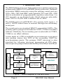
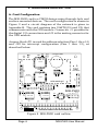
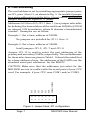
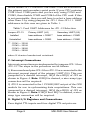
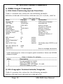
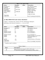
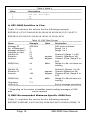
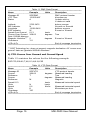
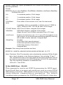
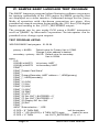
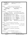
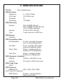
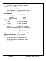
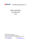
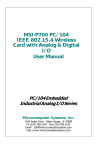
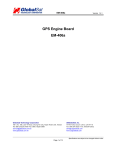
MSI-P600 GPS (Global Positioning System) & Digital I/O Card USER MANUAL PC/104 Embedded Industrial Analog I/O Series Microcomputer Systems, Inc. 1814 Ryder Drive ¨ Baton Rouge, LA 70808 Ph (225) 769-2154 ¨ Fax (225) 769-2155 Email: [email protected] http://www.microcomputersystems.com CONTENTS I. INTRODUCTION 4 II. HARDWARE DESCRIPTION 6 A. Card Configuration B. Card Addressing 6 C. Interrupt Connections D. Digital I/O Registers and Connections 8 7 8 E. GPS Module Reset F. 3.0V Battery 10 G. ET-102 GPS Module 10 10 Interface Connection 10 Interface Description 11 III. GPS SOFTWARE COMMANDS A. NMEA Output Commands 12 12 GGA - Global Positioning System - Fixed Data 12 GGL - Geographic Position - Latitude/Longitude 12 GSA - GNSS DOP and Active Satellites 13 GVS - GNSS Satellites in View 14 RMC - Recommended Minimum Specific GNSS 14 Data VTG - Course over Ground and Ground Speed B. NMEA Input Commands 15 16 Set Serial Port - ID:100 16 Navigation Initiation - ID:101 16 Set DGPS Port - ID:102 17 Query/Rate Control - ID:103 18 LLA Navigation Initialization - ID:104 19 Development Data On/Off - ID:105 20 IV. SAMPLE BASIC LANGUAGE TEST PROGRAM 21 V. SPECIFICATIONS 25 APPENDIX Schematic Diagram of the MSI-P600 27 I. INTRODUCTION The MSI-P600 is a low cost, high performance global positioning system with NMEA 0183 and SiRF binary protocols. Software selectable NMEA protocols using the primary serial port are GGA, GSA, GSV and RMC with optional VTG and GLL. GPS data is selectable at programmable repetitive rates from 1 to 255 seconds, or on demand only. Baud rates are selectable from 1200 to 38,400 with a default rate of 4800. The DGPS protocol is RTCM SC-104, version 2.00, types 1, 2 and 4. DPGS control data is entered through the secondary serial port. The serial ports are standard IBM PC compatible UARTs. The primary port is jumper selectable for COM1, COM3 or an offset address. Similarly, the secondary port is selectable at COM2, COM4 or an offset address. A time mark of 1 PPS is available as an interrupt or as input into modem status line DCD of the secondary UART for synchronizing events. The primary UART interrupt is also provided for allowing interrupt processing of GPS data. Interrupts are jumper selectable for IRQ3 thru IRQ7 and IRQ9. PC/104 16-BIT STACKTHROUGH CONNECTOR ADDRESS JUMPERS PC/104 BUS INTERFACE NETWORK 3.0V BATTERY UART 1 GPS DATA I/O GPS MODULE & ANTENNA MSI-P600 PC/104 BUS INTERRUPT NETWORK UART 2 DIFFERENTIAL GPS CONTROL DIGITAL I/O 4 TTL INPUTS 4 TTL OUTPUTS INTERRUPT JUMPERS Figure 1. Block Diagram of the MSI-P600. Page 4 MSI-P600 User Manual BLOCK DIAGRAM convert the analog signal of each channel into a 12-bit digital signal. Low span and offset errors result in no adjustments being required for these functions. Typical total conversion times of 12 us gives a sample rate of 83 ksps for each group times of 12 us gives a sample rate of 83 ksps for each group of eight channels yielding rates up to 166 ksps for 16 input channels. The card is I/O mapped using 16-bit addressing to select the input channels and device status. Option jumpers are provided by JP1 for specifying the card address (A4 - A15) and interrupt processing is provided for IRQ4 thru IRQ7 and IRQ9 using options jumpers, as described in the next section. Four TTL level digital inputs are provided by status lines CTS and DSR of the primary and secondary UARTs. Four TTL level outputs are provided by OUT1 and OUT2 of these UARTs. The card is supplied with an active antenna having a 5 meter (16.5 ft.) cable and a spacer kit. A sample BASIC program is supplied that illustrates programming of the UART's for various NMEA protocols. Page 5 MSI-P600 User Manual II. HARDWARE DESCRIPTION A. Card Configuration The MSI-P600 card is a CMOS design using through-hole and surface-mounted devices. The card configuration is shown in Figure 2 and a circuit diagram of the network is given in Appendix B. The card contains two UARTS (U4 and U5) that commnucate with the GPS module. Connector J1 provides for the digital I/O connections and J2 is the mating connector for the GPS module. Jumper block JP1 is used for address selection (Pins 1 thru 14) and JP2 for interrupt configuration (Pins 1 thru 12), as described below. C5 A U5 JP3 3.0V BATTERY ON C4 U6 JP4 BATTERY XTAL R4 74HCT126 R3 J2 U4 OFF 16C550 C6 J1 16C550 2 4 6 8 10 12 JP2 18CV8 30 1 3 5 7 9 11 U3 74HCT688 19 0 S/N DC AB 32 10 74HCT245 C3 20 U2 C2 5 U1 C7 C1 + 1 MSI-P600 1 3 5 7 9 11 13 15 17 S1 R5 R6 R7 R8 R9 R10 JP1 R1 15 C8 C9 GPS MODULE 25 R2 S2 MICROCOMPUTER SYSTEMS, INC. Figure 2. MSI-P600 card outline. Page 6 MSI-P600 User Manual B. Card Addressing The card address is set by installing appropriate jumper pairs on JP1, pins 1 thru 13, as shown in Fig. 3. An installed jumper for a given address bit sets the bit to 1 (true) and an uninstalled jumper sets the bit equal to 0 (false). Addresses A15 thru A10 (JP1-1 thru 11) are jumper selectable for defining the base address of the card from 0000H to FC00H on integral 10H boundaries, where H denotes a hexadecimal number. Examples are as follow: Example 1. Set a base address of 0000H. No jumpers are installed for JP1-1 thru 11. Example 2. Set a base address of 3800H. Intall jumpers JP1-5, JP1-7 and JP1-9. Jumper JP1-13 is used to select the port addresses of the primary and secondary UARTs, respectively. The card addresses for these selections are given in Table I. It should be noted that for a base address of zero, the addresses of the UARTs are the standard serial port addresses for the IBM PC. A15 A14 A13 A12 A11 A10 COM1/COM2 o o o o o o o o o o o o o o 1 3 5 7 9 11 13 CAUTION: Make sure that the addresses you select for the MSI-P600 are not in conflict with the serial ports of your CPU card. For example, if your CPU uses COM1 and/or COM2, Figure 3. Jumper block JP1 configuration. Page 7 MSI-P600 User Manual do not install JP1-13 so that COM3 and COM4 are selected for the primary and secondary serial ports. If your CPU contains COM1 thru COM4 ports and you are only using COM1 and COM2, then disable COM3 and COM4 of the CPU card. If this is not permissible, then you will have to select a base address other than 0 by using jumpers for JP1-1 thru JP1-11. UART addresses in this case are given in Table 1. Table 1. Card UART Addresses for JP1-13 Selection. Jumper JP1-13 Primary UART (U4) Secondary UART (U5) Installed base address + COM1** base address + COM2 Uninstalled base address + COM3 base address + COM4 ** COM1 = 3F8H COM2 = 2F8H COM3 = 3E8H COM4 = 2E8H where H denotes hexadecimal notational. C. Interrupt Connections Interrupt connections are implemented by jumpers JP2-1 thru JP2-12. The steps in the procedure are as follows. 1) Even numbered pins JP2-4 thru JP2-10 are connected to the interrupt request signal of the primary UART (U4). This can jumpered to a desired interrupt, IRQ4 thru IRQ9, of JP2 as shown in Figure 4. Note: If IRQ9 is desired, a wire-wrap type connection will be required. 2) JP2-2 is connected to the 1 PULSE/SEC output of the GPS module for use in sychronizing data acquisitions. This can jumpered to a desired interrupt, IRQ4 thru IRQ9, of JP2 as shown in Figure 4. Note: If IRQ3 thru IRQ7 is desired, a wirewrap type connection will be required. D. Digital I/O Registers and Connections. Four digital TTL inputs and four digital TTL outputs are Page 8 MSI-P600 User Manual UART (U4) 6 8 10 12 o o o o o o o o o o o IRQ9 1 IRQ7 3 IRQ6 5 IRQ5 7 IRQ4 9 IRQ3 11 1PPS 2 4 o Figure 4. Interrupt jumper block JP2 configuration. provided by the modem status and modem control registers of UARTs U4 and U5. These I/O are connected to the card via J1 using a 16-pin flat cable connector. Register designations and connector J1 pin assignments are given in Table 2. The inputs and outputs on connector J1 are the inverted values of those read or written in the modem status and control registers. For example, a 1 written to OUT1 of U4 results in a 0 at J1-1 (OUT1_BUFFERED). Similarly, a 1 applied to J1-9 (IN1) Table 2. Digital I/O Register Designations and J1 Pin Assignments. −−−−−−−−−−−−−−−−−−−−−−−−−−−−−−−−−−−−−−−−−−−−−−−−−−−−− Name I/O OUT1_BUFFERED Output OUT2_BUFFERED UART Register J1 Pin* U4 (Primary) OUT1 1 Output U4 (Primary) OUT2 3 OUT3 Output U5 (Secondary) OUT1 5 OUT4 Output U5 (Secondary) OUT2 7 IN1 Input U4 (Primary) CTS 9 IN2 Input U4 (Primary) DSR 11 IN3 Input U5 (Secondary) CTS 13 IN4 Input U5 (Secondary) DSR 15 −−−−−−−−−−−−−−−−−−−−−−−−−−−−−−−−−−−−−−−−−−−−−−−−−−−−− −−−−−−−−−−−−−−−−−−−−−−−−−−−−−−−−−−−−−−−−−−−−−−−−−−−−− * J1 even numbered pins 2 thru 16 are ground. Page 9 MSI-P600 User Manual results in a 0 being read in CTS of U4. E. GPS Module Reset A software reset for the GPS module is provided by DTR of the secondary UART U5. FOr this function to be enabled, jumper JP3 must be installed. In this case, a 1 followed by a 0 write to DTR will reset the GPS module. F. 3.0V Battery A 3.0V battery is included for enhancing GPS data acquisition time by maintaining memory during no power periods. The battery is enabled to the module when jumper JP4 is in the ON position. The unit is shipped with this jumper in the OFF position to conserve battery power. G. ET-102 GPS Module The ET-102 GPS module connects to the MSI-P600 PC/104 card using the 20-pin connector J2 as described in Table 3. 1) Interface Connection. Table 3. Pin-out of the 20-pin Interface Connector J1. -----------------------------------------------------------------------------------------------J2 Pin Name Description Type -----------------------------------------------------------------------------------------------1 2 VANT VDC Antenna DC Voltage 3.8V~6.5V DC Power Input Input Input 3 4 VBAT VDC Backup Battery (Shorted with pin 2) Input Input 5 6 PBRES RESERVED Push Button Reset (Active Low) (Reserved) Input 7 SELECT Down-load data from RS232 to flashROM(Reserved) 8 9 RESERVED RESERVED (Reserved) (Reserved) 10 11 GND TXA Ground Serial Data Output A (GPS Data) 12 13 RXA GND Serial Data Input A (Command) Ground Input 14 15 TXB RXB Serial Data Output B (No Used) Serial Data Input B (DGPS Data) Output Input 16 GND Ground Page 10 Output MSI-P600 User Manual Table 3. Pin-out of the 20-pin Interface Connector J1. (Con’t.) -----------------------------------------------------------------------------------------------J2 Pin Name Description Type -----------------------------------------------------------------------------------------------17 18 RESERVED GND (Reserved) Ground 19 20 TIMEMARK1PPS RESERVED Time Mark Output (Reserved) Output -----------------------------------------------------------------------------------------------2) Interface Description * VANT (antenna DC power input): DC voltage for active antenna. * VDC (DC power input): Main DC supply for a 3.8V ~ 6.5V power module board. * VBAT (Backup battery): Battery backup input that powers the SRAM and RTC when main power is removed .Typical current draw is 10uA. Without an external backup battery or Gold-capacitor, the module/engine board will execute a cold star after every turn on. To achieve the faster startup offered by a hot or warm start, either a battery backup must be connected or a Gold-capacitor should be installed. To maximize battery lifetime, the battery voltage should not exceed the supply voltage and should be between 2.5v and 3.6v. * PBRES (Push button reset): Provides an active-low reset input to the engine board. It causes the engine board to reset and start searching for satellites. * SELECT : Do not connect. * TXA : Primary transmit channel for outputting navigation and measurement data to users navigation software. * RXA : Primary receive channel for receiving software commands to the GPS module. * TXB : Reserved (Do not connect) * RXB : Secondary receive channel for inputting differential corrections to the engine board to enable DGPS navigation. * Time mark : Provides one pulse-per-second output from the engine board that is synchronized to GPS time. * GND : GND provides the system ground for the engine board. Page 11 MSI-P600 User Manual III. GPS SOFTWARE COMMANDS A. NMEA Output Commands 1) GGA-Global Positioning System Fixed Data Table 4 contains the values for the following example: $GPGGA,161229.487,3723.2475,N,12158.3416,W,1,07,1.0,9.0,M,,,,0000*18 Table 4. GGA Data Format -------------------------------------------------------------------------------------------------------Name Example Units Description -------------------------------------------------------------------------------------------------------Message ID $GPGGA GGA protocol header UTC Time 161229.487 hhmmss.sss Latitude 3723.2475 ddmm.mmmm N/S Indicator N N=north or S=south Longitude 12158.3416 dddmm.mmmm E/W Indicator W E=east or W=west Position Fix Indicator 1 See Table 5 Satellites Used 07 Range 0 to 12 HDOP 1.0 Horizontal Dilution of Precision MSL Altitude** 9.0 meters Units M meters Geoid Separation** meters Units M meters Age of Diff. Corr. second Null fields when DGPS is not used Diff. Ref. Station ID 0000 Checksum *18 <CR><LF> End of message termination -----------------------------------------------------------------------------------------------** SiRF Technology Inc. does not support geoid corrections. Values are WGS84 ellipsoid heights. Table 5. Position Fix Indicator -------------------------------------------------------------------------------------------------------Value Description -------------------------------------------------------------------------------------------------------0 Fix not available or invalid 1 GPS SPS Mode, fix valid 2 Differential GPS, SPS Mode , fix valid 3 GPS PPS Mode, fix valid -------------------------------------------------------------------------------------------------------- 2) GLL-Geographic Position-Latitude/Longitude Table 6 contains the values for the following example: $GPGLL,3723.2475,N,12158.3416,W,161229.487,A*2C Page 12 MSI-P600 User Manual Table 6. GLL Data Format -------------------------------------------------------------------------------------------------------Name Example Units Description -------------------------------------------------------------------------------------------------------Message ID $GPGLL GLL protocol header Latitude 3723.2475 ddmm.mmmm N/S Indicator N N=north or S=south Longitude 12158.3416 dddmm.mmmm E/W Indicator W E=east or W=west UTC Position 161229.487 hhmmss.sss Status A A=data valid or V=data not valid Checksum *2C <CR><LF> End of message termination -------------------------------------------------------------------------------------------------------- 3) GSA-GNSS DOP and Active Satellites Table 7 contains the values for the following example: $GPGSA,A,3,07,02,26,27,09,04,15,,,,,,1.8,1.0,1.5*33 Table 7. GSA Data Format -------------------------------------------------------------------------------------------------------Name Example Units Description -------------------------------------------------------------------------------------------------------Message ID $GPGSA GSA protocol header Mode1 A See Table 8 Mode2 3 See Table 9 Satellite Used** 07 Sv on Channel 1 Satellite Used** 02 Sv on Channel 2 ….. Satellite Used** Sv on Channel 12 PDOP 1.8 Position dilution of Precision HDOP 1.0 Horizontal dilution of Precision VDOP 1.5 Vertical dilution of Precision Checksum *33 <CR><LF> End of message termination -------------------------------------------------------------------------------------------------------** Satellite used in solution. Table 8. Mode 1. -------------------------------------------------------------------------------------------------------Value Description -------------------------------------------------------------------------------------------------------M Manual-forced to operate in 2D or 3D mode A 2D automatic-allowed to automatically switch 2D/3D -------------------------------------------------------------------------------------------------------- Page 13 MSI-P600 User Manual Table 9. Mode 2. -------------------------------------------------------------------------------------------------------Value Description -------------------------------------------------------------------------------------------------------1 Fix Not Available 2 2D 3 3D -------------------------------------------------------------------------------------------------------- 4) GSV-GNSS Satellites in View Table 10 contains the values for the following example: $GPGSV,2,1,07,07,79,048,42,02,51,062,43,26,36,256,42,27,27,138,42*71 $GPGSV,2,2,07,09,23,313,42,04,19,159,41,15,12,041,42*41 Table 10. GSV Data Format -------------------------------------------------------------------------------------------------------Name Example Units Description -------------------------------------------------------------------------------------------------------Message ID $GPGSV GSV protocol header No. of Messages** 2 Range 1 to 3 Message Number** 1 Range 1 to 3 Satellites in View 07 Satellite ID 07 Channel 1(Range 1 to 32) Elevation 79 degrees Channel 1(Maximum 90) Azimuth 048 degrees Channel 1(True, Range 0 to 359) SNR(C/No) 42 dBHz Range 0 to 99, null when not tracking ……. ……. Satellite ID 27 Channel 4 (Range 1 to 32) Elevation 27 degrees Channel 4(Maximum 90) Azimuth 138 degrees Channel 4(True, Range 0 to 359) SNR(C/No) 42 dBHz Range 0 to 99,null when not tracking Checksum *71 <CR><LF> End of message termination -----------------------------------------------------------------------------------------------** Depending on the number of satellites tracked multiple messages of GSV data may be required. 5) RMC-Recommended Minimum Specific GNSS Data Table 11 contains the values for the following example: $GPRMC,161229.487,A,3723.2475,N,12158.3416,W,0.13,309.62,120598,,*10 Page 14 MSI-P600 User Manual Table 11. RMC Data Format -------------------------------------------------------------------------------------------------------Name Example Units Description -------------------------------------------------------------------------------------------------------Message ID $GPRMC RMC protocol header UTC Time 161229.487 hhmmss.sss Status A A=data valid or V=data not valid Latitude 3723.2475 ddmm.mmmm N/S Indicator N N=north or S=south Longitude 12158.3416 dddmm.mmmm E/W Indicator W E=east or W=west Speed Over Ground 0.13 knots Course Over Ground 309.62 degrees True Date 120598 ddmmyy Magnetic Variation** 2 degrees E=east or W=west Checksum *10 <CR><LF> End of message termination -----------------------------------------------------------------------------------------------** SiRF Technology Inc. does not support magnetic declination. All “course over ground” data are geodetic WGS48 directions. 6) VTG-Course Over Ground and Ground Speed Table 12 contains the values for the following example: $GPVTG,309.62,T,,M,0.13,N,0.2,K*6E Table 12. VTG Data Format -------------------------------------------------------------------------------------------------------Name Example Units Description -------------------------------------------------------------------------------------------------------Message ID $GPVTG VTG protocol header Course 309.62 degrees Measured heading Reference T True Course degrees Measured heading Reference M Magnetic Speed 0.13 knots Measured horizontal speed Units N knots Speed 0.2 Km/hr Measured horizontal speed Units K Kilometers per hour Checksum *6E <CR><LF> End of message termination ------------------------------------------------------------------------------------------------ Page 15 MSI-P600 User Manual A. NMEA Input Commands 1) Set Serial Port - ID:100 This command message is used to set the protocol (SiRF Binary, NMEA, or USER1) and/or the communication parameters (baud, data bits, stop bits, parity) for PORTA. Generally, this command would be used to switch the module back to SiRF Binary protocol mode where a more extensive command message set is available. For example,to change navigation parameters. When a valid message is received,the parameters will be stored in battery backed SRAM and then the receiver will restart using the saved parameters. Format: $PSRF100,<protocol>,<baud>,<DataBits>,<StopBits>,<Parity>*CKSUM<CR><LF> <protocol> <baud> <DataBits> <StopBits> <Parity> 0=SiRF Binary, 1=NMEA, 4=USER1 1200, 2400, 4800, 9600, 19200, 38400 8,7. Note that SiRF protocol is only valid for 8 Data bits 0,1 0=None, 1=Odd, 2=Even Example 1: Switch to SiRF Binary protocol at 9600,8,N,1 $PSRF100,0,9600,8,1,0*0C<CR><LF> Example 2: Switch to User1 protocol at 38400,8,N,1 $PSRF100,4,38400,8,1,0*38<CR><LF> Note: Checksum Field: The absolute value calculated by exclusive-OR the 8 data bits of each character in the Sentence,between, but excluding “$” and “*”. The hexadecimal value of the most significant and least significant 4 bits of the result are convertted to two ASCII characters (0-9,A-F) for transmission. The most significant character is transmitted first. <CR><LF> : Hex 0D 0A 2) Navigation Initialization - ID:101 This command is used to initialize the module for a warm start, by providing current position (in X, Y, Z coordinates), clock offset, and time. This enables the receiver to search for the correct satellite signals at the correct signal parameters. Correct initialization parameters will enable the receiver to acquire signals more quickly, and thus, produce a faster navigational solution. When a valid Navigation Initialization command is received, the receiver will Page 16 MSI-P600 User Manual restart using the input parameters as a basis for satellite selection and acquisition. Format: $PSRF101,<X>,<Y>,<Z>,<ClkOffset>,<TimeOfWeek>,<WeekNo>,<chnlCount>,<ResetCfg> *CKSUM<CR><LF> <X> X coordinate position, 32-bit integer <Y> Y coordinate position, 32-bit integer <Z> Z coordinate position, 32-bit integer <ClkOffset> value Clock offset of the receiver in Hz, Use 0 for last saved if available. If this is unavailable, a default value of 75000 for GSP1, 95000 for GSP 1/LX will be used. 32-bit integer. <TimeOf Week> GPS Time Of Week, unsigned 32-bit integer. <WeekNo> GPS Week Number, unsigned 16-bit integer. (Week No and Time Of Week calculation from UTC time) <chnlCount> Number of channels to use.1-12. If your CPU throughput is not high enough, you could decrease needed throughput by reducing the number of active channels. Unsigned Byte. <ResetCfg> bit mask 0×01=Data Valid warm/hotstarts=1 0×02=clear ephemeris warm start=1 0×04=clear memory. Cold start=1 Unsigned Byte Example: Start using known position and time. $PSRF101,-2686700,-4304200,3851624,96000,497260,921,12,3*7F Note: Checksum Field: The absolute value calculated by exclusive-OR the 8 data bits of each character in the Sentence,between, but excluding “$” and “*”. The hexadecimal value of the most significant and least significant 4 bits of the result are convertted to two ASCII characters (0-9,A-F) for transmission. The most significant character is transmitted first. <CR><LF> : Hex 0D 0A 3) Set DGPS Port - ID:102 This command is used to set PORT B parameters for DGPS input. Serial Port B that is an input only serial port used to receive RTCM differential corrections. Differential receivers may output corrections using different communication parameters. The default communication parameters for PORT B are 9600 Baud, 8 data bits, Page 17 MSI-P600 User Manual 0 stop bits, and no parity. If a DGPS receiver is used which has different communication parameters, use this command to allow the receiver to correctly decode the data. When a valid message is received, the parameters will be stored in battery backed SRAM and then the receiver will restart using the saved parameters. Format: $PSRF102,<Baud>,<DataBits>,<StopBits>,<Parity>*CKSUM<CR><LF> <baud> <DataBits> <StopBits> <Parity> 1200,2400,4800,9600,19200,38400 8 0,1 0=None,Odd=1,Even=2 Example: Set DGPS Port to be 9600,8,N,1 $PSRF102,9600,8,1.0*12 Note: Checksum Field: The absolute value calculated by exclusive-OR the 8 data bits of each character in the Sentence,between, but excluding “$” and “*”. The hexadecimal value of the most significant and least significant 4 bits of the result are convertted to two ASCII characters (0-9,A-F) for transmission. The most significant character is transmitted first. <CR><LF> : Hex 0D 0A 4) Query/Rate Control - ID:103 This command is used to control the output of standard NMEA messages GGA, GLL, GSA, GSV, RMC, and VTG. Using this command, a standard NMEA message may be polled once, or setup for periodic output. Checksums may also be enabled or disabled depending on the needs of the receiving program. NMEA message settings are saved in battery backed memory for each entry when the message is accepted. Format: $PSRF103,<msg>,<mode>,<rate>,<cksumEnable>*CKSUM<CR><LF> <msg> <mode> <rate> <cksumEnable> 0=GGA,1=GLL,2=GSA,3=GSV,4=RMC,5=VTG 0=SetRate,1=Query Output every <rate>seconds, off=0,max=255 0=disable Checksum,1=Enable checksum for message Example 1: Query the GGA message with checksum enabled. $PSRF103,00,01,00,01*25 Example 2: Enable VTG message for a 1Hz constant output with checksum enabled. Page 18 MSI-P600 User Manual $PSRF103,05,00,01,01*20 Example 3: Disable VTG message $PSRF103,05,00,00,01*21 Note: Checksum Field: The absolute value calculated by exclusive-OR the 8 data bits of each character in the Sentence,between, but excluding “$” and “*”. The hexadecimal value of the most significant and least significant 4 bits of the result are convertted to two ASCII characters (0-9,A-F) for transmission. The most significant character is transmitted first. <CR><LF> : Hex 0D 0A 5). LLA Navigation lnitialization - ID:104 (Parameters required to start using Lat/Lon/Alt) This command is used to initialize the module for a warm start, by providing current position (in Latitude, Longitude, Altitude coordinates), clock offset, and time. This enables the receiver to search for the correct satellite signals at the correct signal parameters. Correct initialization parameters will enable the receiver to acquire signals more quickly and will produce a faster navigational soution. When a valid LLA Navigation Initialization command is received,the receiver will restart using the input parameters as a basis for satellite selection and acquisition. Format: $PSRF104,<Lat>,<Lon>,<Alt>,<ClkOffset>,<TimeOfWeek>,<WeekNo>,<ChannelCount>, <ResetCfg>*CKSUM<CR><LF> <Lat> <Lon> Latitude position, assumed positive north of equator and negative south of equator float, possibly signed Longitude position, it is assumed positive east of Greenwich and negative west of Greenwich. Floating point number, possibly signed. <Alt> Altitude position. Floating point number, possibly signed. <ClkOffset> Clock Offset of the receiver in Hz, use 0 for last saved value if available. If this is unavailable, a default value of 75000 for GSP1, 95000 for GSP1/LX will be used. 32-bit integer. <TimeOfWeek> GPS Time Of Week, unsigned 32-bit integer. <WeekNo> GPS Week Number, unsigned 16-bit integer. <ChannelCount> Number of channels to use. 1-12, unsigned Byte. <ResetCfg> bit mask Page 19 0×01=Data Valid warm/hot starts=1 0×02=clear ephemeris warm start=1 0×04=clear memory. Cold start=1 Unsignd Byte. MSI-P600 User Manual Example: Start using known position and time. $PSRF104,37.3875111,-121.97232,0,96000,237759,922,12,3*37 F). Development Data On/Off - ID:105 (Switch Development Data Messages On/Off) Use this command to enable development debug information if you are having trouble getting commands accepted. Invalid commands will generate debug information that should enable the user to determine the source of the command rejection. Common reasons for input command rejection are invalid checksum or parameter out of specified range. This setting is not preserved across a module reset. Format: PSRF105,<debug>*CKSUM<CR><LF> <debug> 0=Off,1=On Example: Debug On, $PSRF105,1*3E Example: Debug Off, $PSRF105,0*3F Note: Checksum Field: The absolute value calculated by exclusive-OR the 8 data bits of each character in the Sentence,between, but excluding “$” and “*”. The hexadecimal value of the most significant and least significant 4 bits of the result are convertted to two ASCII characters (0-9,A-F) for transmission. The most significant character is transmitted first. <CR><LF> : Hex 0D 0A Page 20 MSI-P600 User Manual IV. SAMPLE BASIC LANGUAGE TEST PROGRAM The BASIC language program below illustrates software sequences for issuing commands to the GPS engine for NMEA protocols that are displayed on a video monitor. Command strings for the Query Mode of operation with checksum generation are given. Also provided are simple routines for inputting the /IN1 thru /IN4 digital inputs and writing to the /OUT1_BUFFERED output. The program can be run under DOS using a BASIC interpreter such as QBASIC by Microsoft Corporation. An interpreter can be provided at no charge upon request. TEST PROGRAM LISTING ‘MSI-P600 BASIC test program - 01-30-04 primary = &H3E8 ‘Default value for Primary Uart is COM3. ‘Change if other address is desired. secondary = primary - &H100 ‘Default value for secondary ‘Uart is COM4. again: CLS GOSUB initUART1 ‘init primary UART GOSUB initUART2 ‘init secondary UART PRINT “” PRINT “Present Card Status” PRINT “” PRINT “Primary/Secondary UART address = “; HEX$(primary); PRINT “/”; HEX$(secondary) PRINT “” PRINT “(0) GGA” PRINT “(1) GLL” PRINT “(2) GSA” PRINT “(3) GSV” PRINT “(4) RMC” PRINT “(5) VTG” PRINT “(6) Set /OUT1_BUFFERED = 0” PRINT “(7) Set /OUT1_BUFFERED = 1” PRINT “(8) Display /IN1 thru /IN4” PRINT “(9) Exit” PRINT “” INPUT “Enter selection - “, GP$ IF GP$ = “9” THEN END ‘exit the program IF GP$ = “” OR VAL(GP$) > 9 THEN GOTO again ‘branch on error IF GP$ = “6” THEN ‘set /OUT1_BUFFERED (J1-1) = 0 Page 21 MSI-P600 User Manual z=0 GOSUB setDOutput GOTO again END IF IF GP$ = “7” THEN ‘set /OUT1_BUFFERED = 1 z=1 GOSUB setDOutput GOTO again END IF IF GP$ = “8” THEN ‘display digital inputs GOSUB getDInputs GOTO again END IF FOR k = 0 TO 5 GPS$ = “PSRF103,” + CHR$(48 + k) + “,00,00,01” ’reset SetRate ‘mode GOSUB sendGPS ‘send GPS$ to primary UART NEXT k GPS$ = “PSRF103,” + GP$ + “,01,00,01” mode GOSUB sendGPS ‘send GPS$ to primary UART start: CLS ‘set Query ‘clear display screen repeat: C$ = INKEY$ IF C$ <> “” THEN GOTO again GOSUB getchar GOTO repeat initUART1: ‘initialize GPS primary UART baddr = primary OUT baddr + 3, &H80 OUT baddr, 24 OUT baddr + 1, 0 OUT baddr + 3, 3 x = INP(baddr) x = INP(baddr) RETURN initUART2: ‘8 data bits, 1 stop bit, no parity ‘initialize GPS secondary UART baddr2 = secondary OUT baddr2 + 3, &H80 OUT baddr2, 24 Page 22 ‘set DLAB = 1 ‘BAUD = 4800 ‘set DLAB = 1 ‘BAUD = 4800 MSI-P600 User Manual OUT baddr2 + 1, 0 OUT baddr2 + 3, 3 x = INP(baddr2) x = INP(baddr2) RETURN getchar: ‘8 data bits, 1 stop bit, no parity ‘dummy reads ‘get GPS character from the primary UART IF (INP(baddr + 5) AND 1) = 1 THEN ‘test DATA READY status z = INP(baddr) ‘input character PRINT CHR$(z); ‘display character END IF RETURN getDInputs: ‘get digital inputs from /CTS & /DSR of UARTS z = INP(baddr + 6) AND &H30 ‘get CTS & DTR of primary UART z1 = INP(baddr2 + 6) AND &H30 ‘get CTS & DTR of secondary UART CLS ‘clear screen PRINT “”: PRINT “Digital Inputs from J1”: PRINT “” IF ((z AND &H10) / &H10) > 0 THEN q = 0 ELSE q = 1 ‘invert CTS bit PRINT “/IN1 (J1-9) = “; q ‘display /IN1 IF ((z AND &H20) / &H20) > 0 THEN q = 0 ELSE q = 1 ‘invert DSR bit PRINT “/IN2 (J1-9) = “; q ‘display /IN2 IF ((z1 AND &H10) / &H10) > 0 THEN q = 0 ELSE q = 1 ‘invert /CTS bit PRINT “/IN3 (J1-9) = “; q ‘display /IN3 IF ((z1 AND &H20) / &H20) > 0 THEN q = 0 ELSE q = 1 ‘invert /CTS bit PRINT “/IN4 (J1-9) = “; q ‘display /IN4 WHILE INKEY$ = “”: WEND ‘delay until keyboard character entry RETURN sendchar: ‘send a string character to primary UART WHILE (INP(baddr + 5) AND &H40) <> &H40: WEND ‘check xmitter empty OUT baddr, ASC(C$) ‘transmit character RETURN sendchar1: ‘send a numeric constant to primary UART WHILE (INP(baddr + 5) AND &H40) <> &H40: WEND OUT baddr, cc RETURN setDOutput: ‘set OUT1_BUFFERED (J1-1) Hi or Lo IF z = 0 THEN z = INP(baddr + 4) Page 23 ‘set OUT1_BUFFERED (J1-1) = 0 ‘get MODEM control register contents MSI-P600 User Manual z = z OR 4 OUT baddr + 4, z ELSEIF z = 1 THEN z = INP(baddr + 4) z = z AND NOT 4 OUT baddr + 4, z END IF RETURN ‘set corresponding OUT1 bit in z ‘output to Modem control register ‘set OUT1_BUFFERED (J1-1) = 1 ‘get MODEM control register contents ‘reset corresponding OUT1 bit in z ‘output to Modem control register sendGPS: ‘send command string of GPS$ to primary UART checksum = 0 ‘determine checksum value FOR i = 1 TO LEN(GPS$) checksum = checksum XOR ASC(MID$(GPS$, i, 1)) NEXT i GPS$ = “$” + GPS$ + “*” + RIGHT$(HEX$(checksum), 2) FOR i = 1 TO LEN(GPS$) ‘send command string C$ = MID$(GPS$, i, 1) GOSUB sendchar NEXT i cc = 13 ‘send carriage return GOSUB sendchar1 cc = 10 ‘send line feed GOSUB sendchar1 RETURN Page 24 MSI-P600 User Manual V. SPECIFICATIONS PC/104 8-bit, stackthrough GPS Receiver Frequency L1, 1575.42 MHz C/A Code 1.023 MHz rate Channels 12 Sensitivity -170 bBW GPS Accuracy Position 15m 2d RMS (SA off) 10m 2d RMS, WAAS (SA off) 1~5m, DGPS corrected Velocity 0.1m/sec 95% (SA off) Time 1 usec sync'ed to GPS time GPS Datum WGS-84 GPS Acquisition Rate Re-acquisition 0.1 sec., average (recovery time for being interrupted) Hot Start 8 sec., average (with ephemeris and almanac valid) Warm Start 38 sec., average (with almanac but not ephemeris) Cold Start 48 sec., average (neither almanac nor ephemeris) GPS Dynamic Condition Altitude 18,000 m (60,000 ft.) max Velocity 515 m/sec (1000 knots) max GPS Code Type ASCII GPS Protocol NMEA 0183 GGA, GSA, GSV, RMC (VGT and GLL optional) SiRF Binary Page 25 Position, velocity,altitude, status and control MSI-P600 User Manual DGPS Protocol RTCM SC-01, Ver. 2.00, types 1, 2 and 9 GPS Time Mark (1 PPS) Pulse Duration 100ms Time Reference Positive Transition Edge Synchronization To GPS seconds, +/- 1us GPS Antenna Active with 5m (16.5 ft) cable Connector Type MSI-P600 MCX MSI-P600-SMA SMA Digital I/O Port 4 Input TTL level (Inverted) 4 Output TTL level (Inverted) Serial Ports Primary NMEA 0183 I/O data (jumper selectable as COM1, COM3 or offset) Secondary DGPS control data (jumper selectable as COM2, COM4 or offset) Option Jumpers .025" square posts, 0.1" grid Digital I/O Connector 3M 30316-5002 Electrical & Environmental +5V @ 70 mA typical, continuous mode +5V @ 45 mA typical, power save mode -40° to 80° C Page 26 MSI-P600 User Manual APPENDIX Schematic Diagrams of the MSI-P600 1) P600-1.sch - Schematic sheet 1 of 2. See p600-1.pdf 2) P600-1.sch - Schematic sheet 2 of 2. See p600-2.pdf Page 27 MSI-P600 User Manual