1
Inverter
MX2/RX/LX Series
Drive Programming
User’s Manual
3G3MX2 Series
3G3RX Series
3G3LX Series
CX-Drive
I580-E2-01A
OMRON, 2014
All rights reserved. No part of this publication may be reproduced, stored in a retrieval system, or transmitted, in any
form, or by any means, mechanical, electronic, photocopying, recording, or otherwise, without the prior written
permission of OMRON.
No patent liability is assumed with respect to the use of the information contained herein. Moreover, because OMRON
is constantly striving to improve its high-quality products, the information contained in this manual is subject to change
without notice. Every precaution has been taken in the preparation of this manual. Nevertheless, OMRON assumes no
responsibility for errors or omissions. Neither is any liability assumed for damages resulting from the use of the
information contained in this publication.
Trademarks
• Sysmac and SYSMAC are trademarks or registered trademarks of OMRON Corporation in Japan and other countries
for OMRON factory automation products.
• Windows, Windows XP, Windows Vista, Windows 7, Windows 8, and Excel are registered trademarks of Microsoft
Corporation in the USA and other countries.
• EtherCAT® is registered trademark and patented technology, licensed by Beckhoff Automation GmbH, Germany.
• ODVA, CIP, CompoNet, DeviceNet, and EtherNet/IP are trademarks of ODVA.
Other company names and products names in this document are the trademarks or registered trademarks of their
respective companies.
Introduction
Introduction
Thank you for purchasing the Inverter/Servo support tool CX-Drive and 3G3MX2/3G3RX/3G3LX Series
Inverter.
This manual describes the specifications and operating methods of the Drive Programming for the
inverter.
When you use this product, refer to the MX2 Series User's Manual (I570-E2) or the RX User's Manual
(I560-E2), besides the CX-Drive Operation Manual (W453).
Intended Readers
This manual is intended for the following personnel, who must also have knowledge of electrical systems (an electrical engineer or the equivalent).
• Personnel in charge of introducing FA systems.
• Personnel in charge of designing FA systems.
• Personnel in charge of installing and connecting FA systems.
• Personnel in charge of managing FA systems and facilities.
Notice
This manual contains information you need to know to use the Drive Programming.
Before using this product, read this manual and gain a full understanding of the information provided
herein.
After you finished reading this manual, keep it in a convenient place so that it can be referenced at any
time.
Make sure this manual is delivered to the end user.
Drive Programming User’s Manual (I580-E2)
1
Manual Configuration
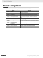
Manual Configuration
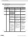
This manual is compiled section by section for user's convenience as follows.
Section
Section 1
Section 2
Section 3
Section 4
Section 5
Section 6
Section 7
Section 8
Section 9
2
Overview
This section describes an overview and the system configuration
Overview
of the Drive Programming.
Specifications
This section describes the specifications of the Drive Programming.
Operation Procedure for Drive This section describes the operation procedure of the Drive
Programming
Programming, related parameters, and program structures.
This section describes how to start the Drive Programming
Drive Programming Editor
Editor, saving and loading data, and details on parts of the
Editor.
This section describes the user variables provided for
Drive Programming User Variables
Drive Programming.
Drive Programming
This section describes the commands provided for Drive Programming.
Commands
Precautions for Use of
This section describes the precautions for use of parameters for
Parameters for Drive
the Drive Programming.
Programming
This section describes the program operation at the time of error
Errors and Remedies
occurrence, the errors that are specific to the Drive
Programming, as well as the causes and remedies.
LX inverter
This section describes the LX inverter specific functions.
Drive Programming User’s Manual (I580-E2)
Manual Structure
Manual Structure
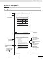
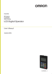
Page Structure
The following page structure and symbol icons are used in this user's manual.
Level 1 heading
Level 2 heading
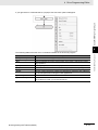
8 Errors and Remedies
8-1
Troubleshooting
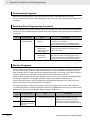
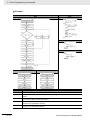
This section describes the program operation at the time of error occurrence, the error codes that are
specific to the DriveProgramming, and the remedies for them.
Level 3 heading
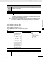
8-1-1
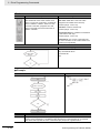
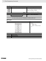
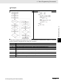
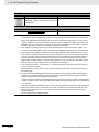
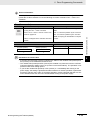
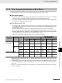
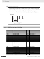
DriveProgramming Operation on Error
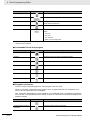
Basically, even if the inverter detects a trip during the DriveProgramming operation, the operation is
continued. However, if any of E43 to E45 trips related to the DriveProgramming is detected, the operation is stopped. Or, with the “on trip goto” command, the program can jump to other process after a trip
occurred.
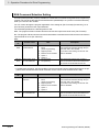
With/without
“on trip goto”
Without
With
User trip
E50 to E59
Operation is continued.
After the “on trip goto”
command is executed, the
program jumps to the
specified label and the
operation is continued.
Error status
DriveProgramming-related
Trip E43 to E45
Program is stopped.
Program is stopped.
Other trips
Operation is continued.
After the “on trip goto”
command is executed, the
program jumps to the
specified label and the
operation is continued.
Precautions for Safe Use
When execution of the DriveProgramming program is stopped, the status before the program
stop is retained for multi-function outputs controlled by the DriveProgramming.
For this reason, the wiring must be made so that the stop of the DriveProgramming program in
the inverter can be detected by the DriveProgramming start signal and the alarm (trip) signal,
and the inverter's peripheral devices can be stopped safely.
8-2
Manual Name
DriveProgramming User’s Manual (I580-E2)
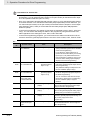
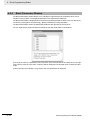
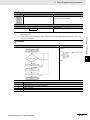
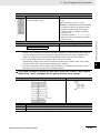
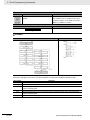
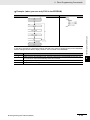
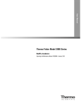
4 DriveProgramming Editor
4-7
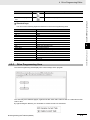
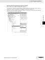
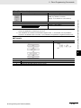
Click the [Transfer from Drive] icon in the toolbar of the DriveProgramming Editor.
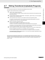
4-7 Editing Transferred (Uploaded) Programs
4-7-1
Editing Transferred (Uploaded) Programs
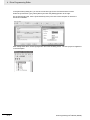
A program is transferred from the drive (inverter) and automatically displayed in the designer
area of the DriveProgramming Editor.
4
Editing Transferred (Uploaded) Programs
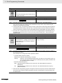
You can edit the program which is saved in the inverter after transferring (uploading) it from the inverter.
Follow the steps described below to edit the program.
1
Operation Steps
Open the DriveProgramming Editor.
The DriveProgramming auxiliary windows (Command box, User Parameters and Properties)
are displayed automatically.
Describes the
operation steps.
2
3
4
Go online with the CX-Drive. From the Menu, select [Drive] - [Work Online]. Or, click the [Work
Online] icon in the CX-Drive toolbar.
Edit the transferred (uploaded) program.
Therefore, the transferred (uploaded) program will be displayed as a text program.
To display it as a flowchart program, click [Convert whole program to Flowchart] in the toolbar of
the DriveProgramming Editor and convert the program to flowchart.
Note, Supplementary
Information, Reference
Target
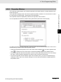
Precautions for Safe Use
Perform operations such as program compilation, transferring to the inverter, and data saving.
• Execute compilation and check for any compilation errors in the program.
• You can transfer the program to the inverter when the compilation is finished successfully.
• To save the program, save the whole project. Or, you can save the program separately by
using the function that exports programs.
A note, supplementary
information, reference
target, etc. are provided
with difference icons.
When the DriveProgramming programs exist, you can transfer them to/from the inverter by using
[Transfer to Drive] or [Transfer from Drive] icon in the CX-Drive toolbar. In this case, you need to select
"programs" when a message dialog appears and asks you whether to transfer the parameters, programs, or both.
DriveProgramming User’s Manual (I580-E2)
4-7-1 Editing Transferred (Uploaded) Programs
The programs that exist in the inverter are the downloaded "programs after compilation".
Level 2 heading
Shows which sub-section
the content of the current
page belongs to.
Section Number of Level 1
heading
Shows which section the
content of the current
page belongs to.
Level 3 heading
Shows which paragraph
the content of the current
page belongs to.
4 - 21
Note The above page is only a sample for illustrative purposes. It is not the actual content of the manual.
Drive Programming User’s Manual (I580-E2)
3
Manual Structure
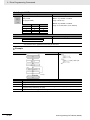
Special Information
Special information in this user's manual is classified as follows:
Precautions for Safe Use
Precautions on what to do and what not to do to ensure safe usage of the product.
Precautions for Correct Use
Precautions on what to do and what not to do to ensure proper operation and performance.
Additional Information
Additional information to read as required.
This information is provided to increase understanding or make operation easier.
Version Information
Information on differences in specifications and functionality for inverters with different unit versions and for different versions of the CX-Drive is given.
4
Drive Programming User’s Manual (I580-E2)
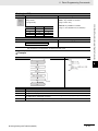
Sections in this Manual
Sections in this Manual
1
2
1
Overview
3
2
Specifications
4
3
Operation Procedure for Drive Programming
4
Drive Programming Editor
6
5
Drive Programming User Variables
7
6
5
8
Drive Programming Commands
9
7
Precautions for Use of Parameters for Drive Programming
8
Errors and Remedies
9
LX inverter
Drive Programming User’s Manual (I580-E2)
5
CONTENTS
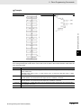
CONTENTS
Introduction .............................................................................................................. 1
Manual Configuration .............................................................................................. 2
Manual Structure ...................................................................................................... 3
Sections in this Manual ........................................................................................... 5
CONTENTS................................................................................................................ 6
Terms and Conditions Agreement .......................................................................... 9
Safety Precautions ................................................................................................. 10
Precautions for Safe Use....................................................................................... 12
Regulations and Standards ................................................................................... 13
Related Manuals ..................................................................................................... 14
Revision History ..................................................................................................... 15
Section 1
Overview
1-1
Overview of Drive Programming.......................................................................................... 1-2
1-2
Preparation and System Configuration ............................................................................... 1-4
Section 2
2-1
Section 3
Specifications
Specifications ........................................................................................................................ 2-2
Operation Procedure for Drive Programming
3-1
Operation Procedure............................................................................................................. 3-2
3-2
Parameters Related to Drive Programming ........................................................................ 3-5
3-3
Program Structure ............................................................................................................... 3-13
3-3-1
3-3-2
3-3-3
3-3-4
3-3-5
3-3-6
6
Tasks ......................................................................................................................................... 3-13
Subroutines ............................................................................................................................... 3-13
Task Processing ........................................................................................................................ 3-13
Drive Programming Start/Stop and Task Operation .................................................................. 3-15
Drive Programming Restart....................................................................................................... 3-17
Task Operation on Trip.............................................................................................................. 3-18
Drive Programming User’s Manual (I580-E2)
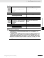
CONTENTS
Section 4
4-1
4-2
Drive Programming Editor
Starting Drive Programming Editor ..................................................................................... 4-2
Parts of Drive Programming Editor...................................................................................... 4-6
4-2-1
4-2-2
4-2-3
4-2-4
4-2-5
4-2-6
4-2-7
Drive Programming Editor .......................................................................................................... 4-6
Toolbar ........................................................................................................................................ 4-6
Drive Programming Area ............................................................................................................ 4-9
Toolbox Window........................................................................................................................ 4-13
Block Parameters Window........................................................................................................ 4-14
Properties Window.................................................................................................................... 4-15
Error List Tab in Output Window ............................................................................................... 4-16
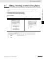
4-3
Adding, Deleting and Renaming Tasks ............................................................................. 4-17
4-4
Inserting, Deleting and Calling Subroutines..................................................................... 4-18
4-5
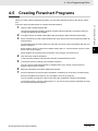
Creating Flowchart Programs ............................................................................................ 4-19
4-6
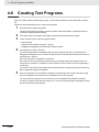
Creating Text Programs ...................................................................................................... 4-20
4-7
Editing Transferred (Uploaded) Programs ........................................................................ 4-21
4-8
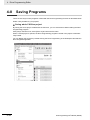
Saving Programs ................................................................................................................. 4-22
4-9
Transferring and Verifying Programs ................................................................................ 4-24
4-10 Executing Programs (Drive Programming Function Selection)...................................... 4-25
4-11 Other Useful Functions....................................................................................................... 4-28
Section 5
Drive Programming User Variables
5-1
User Variables and User Parameters................................................................................... 5-2
5-2
Input/Output Terminal Variables .......................................................................................... 5-5
5-3
Timer Variables .................................................................................................................... 5-10
5-4
Inverter Setting Variables ................................................................................................... 5-12
5-5
Inverter Monitor Variables .................................................................................................. 5-14
5-6
Multi-function Input Variables ............................................................................................ 5-17
5-7
Multi-function Output Variables ......................................................................................... 5-20
Section 6
Drive Programming Commands
6-1
Command Categories ........................................................................................................... 6-2
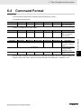
6-2
Command Format.................................................................................................................. 6-3
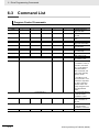
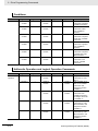
6-3
Command List........................................................................................................................ 6-4
6-4
Program Control Commands ............................................................................................. 6-10
6-5
Arithmetic Operation and Logical Operation Commands ............................................... 6-23
6-6
I/O Control Commands ....................................................................................................... 6-36
6-7
Timer Control Commands .................................................................................................. 6-46
6-8
Parameter Control Commands........................................................................................... 6-52
6-9
Inverter Control Commands ............................................................................................... 6-58
Drive Programming User’s Manual (I580-E2)
7
CONTENTS
Section 7
Precautions for Use of Parameters for Drive Programming
7-1
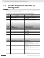
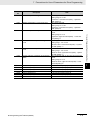
Inverter Parameters Affected by Setting Order .................................................................. 7-2
7-2
Parameters Affected by Rated Current [%] ......................................................................... 7-4
7-3
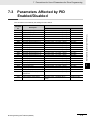
Parameters Affected by PID Enabled/Disabled .................................................................. 7-5
Section 8
8-1
Errors and Remedies
Troubleshooting .................................................................................................................... 8-2
8-1-1
8-1-2
8-1-3
Section 9
LX inverter
9-1
Preparation and System Configuration ............................................................................... 9-2
9-2
Specifications ........................................................................................................................ 9-3
9-3
Drive Programming Editor.................................................................................................... 9-5
9-3-1
9-4
9-5
Input/Output Terminal Variables .................................................................................................. 9-6
Multi-function Input Variables .................................................................................................... 9-10
Multi-function Output Variables ................................................................................................. 9-11
Drive Programming Commands......................................................................................... 9-12
9-5-1
9-5-2
9-6
Executing a Program................................................................................................................... 9-5
Drive Programming User Variables ..................................................................................... 9-6
9-4-1
9-4-2
9-4-3
I/O Control Commands ............................................................................................................. 9-12
Inverter Control Commands ...................................................................................................... 9-16
Precautions for Use of Parameters for Drive Programming ........................................... 9-18
9-6-1
8
Drive Programming Operation on Error ...................................................................................... 8-2
Drive Programming Operation on Error Reset ............................................................................ 8-3
Alarm Code List........................................................................................................................... 8-4
Parameters Affected by Rated Current (%) .............................................................................. 9-18
Drive Programming User’s Manual (I580-E2)
Terms and Conditions Agreement
Terms and Conditions Agreement
WARRANTY
• The warranty period for the Software is one year from the date of purchase, unless otherwise specifically agreed.
• If the User discovers defect of the Software (substantial non-conformity with the manual), and
return it to OMRON within the above warranty period, OMRON will replace the Software without
charge by offering media or download from OMRON’s website. And if the User discovers defect of
media which is attributable to OMRON and return it to OMRON within the above warranty period,
OMRON will replace defective media without charge. If OMRON is unable to replace defective
media or correct the Software, the liability of OMRON and the User’s remedy shall be limited to
the refund of the license fee paid to OMRON for the Software.
LIMITATION OF LIABILITY
• THE ABOVE WARRANTY SHALL CONSTITUTE THE USER’S SOLE AND EXCLUSIVE REMEDIES AGAINST OMRON AND THERE ARE NO OTHER WARRANTIES, EXPRESSED OR
IMPLIED, INCLUDING BUT NOT LIMITED TO, WARRANTY OF MERCHANTABILITY OR FITNESS FOR PARTICULAR PURPOSE. IN NO EVENT, OMRON WILL BE LIABLE FOR ANY
LOST PROFITS OR OTHER INDIRECT, INCIDENTAL, SPECIAL OR CONSEQUENTIAL DAMAGES ARISING OUT OF USE OF THE SOFTWARE.
• OMRON SHALL HAVE NO LIABILITY FOR DEFECT OF THE SOFTWARE BASED ON MODIFICATION OR ALTERNATION TO THE SOFTWARE BY THE USER OR ANY THIRD PARTY.
• OMRON SHALL HAVE NO LIABILITY FOR SOFTWARE DEVELOPED BY THE USER OR ANY
THIRD PARTY BASED ON THE SOFTWARE OR ANY CONSEQUENCE THEREOF.
APPLICABLE CONDITIONS
USER SHALL NOT USE THE SOFTWARE FOR THE PURPOSE THAT IS NOT PROVIDED IN
THE ATTACHED USER MANUAL.
CHANGE IN SPECIFICATION
The software specifications and accessories may be changed at any time based on improvements
and other reasons.
ERRORS AND OMISSIONS
The information in this manual has been carefully checked and is believed to be accurate; however,
no responsibility is assumed for clerical, typographical, or proofreading errors, or omissions.
Drive Programming User’s Manual (I580-E2)
9
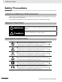
Safety Precautions
Safety Precautions
Indications and Meanings of Safety Information
In this manual, the following precautions and signal words are used to provide information to ensure the
safe use of the Drive Programming.
The information provided here is vital to safety. Strictly observe the precautions provided.
Meanings of Signal Words
WARNING
Caution
Indicates a potentially hazardous situation which, if not avoided, could
result in death or serious injury. Additionally, there may be severe property
damage.
Indicates a potentially hazardous situation which, if not avoided, may result
in minor or moderate injury, or property damage.
Alert Symbols in this Document
This symbol indicates a prohibited item (an item you must not do).
The specific instruction is indicated using an illustration or text inside or near
.
The symbol shown to the left indicates "disassembly prohibited."
This symbol indicates danger and caution.
The specific instruction is indicated using an illustration or text inside or near
.
The symbol shown to the left indicates "beware of electric shock."
This symbol indicates danger and caution.
The specific instruction is indicated using an illustration or text inside or near
.
The symbol shown to the left indicates "non-specific general danger."
This symbol indicates caution (warnings included).
The specific instruction is indicated using an illustration or text inside or near
.
The symbol shown to the left indicates "risk of hot surface."
This symbol indicates a compulsory item (an item that must be done).
The specific instruction is indicated using an illustration or text inside or near
.
The symbol shown to the left indicates "general compulsory items."
This symbol indicates a compulsory item (an item that must be done).
The specific instruction is indicated using an illustration or text inside or near
.
The symbol shown to the left indicates "grounding required."
10
Drive Programming User’s Manual (I580-E2)
Safety Precautions
WARNING
Turn off the power supply and implement wiring correctly.
Not doing so may result in a serious injury due to an electric shock.
Wiring work must be carried out only by qualified personnel.
Not doing so may result in a serious injury due to an electric shock.
Do not change wiring and slide switches, put on or take off Operator and optional devices,
replace cooling fans while the input power is being supplied.
Doing so may result in a serious injury due to an electric shock.
Be sure to ground the unit. Not doing so may result in a serious injury due to an electric shock
or fire.
(200-V class: type-D grounding, 400-V class: type-C grounding)
Do not remove the terminal cover during the power supply and 10 minutes after the power shut off.
Doing so may result in a serious injury due to an electric shock.
Do not operate the Operator or switches with wet hands.
Doing so may result in a serious injury due to an electric shock.
Inspection of the inverter must be conducted after the power supply was turned off.
Not doing so may result in a serious injury due to an electric shock.
The main power supply is not necessarily shut off even if the emergency shut off function is activated.
Do not touch the inverter fins, braking resistors and the motor, which become too hot during the
power supply and for some time after the power shut off.
Doing so may result in a burn.
Caution
Do not connect resistors to the terminals (1, P/2, N/) directly.
Doing so might result in a small-scale fire, heat generation, or damage to the unit.
Install a stop motion device to ensure safety. Not doing so might result in a minor injury.
(A holding brake is not a stop motion device designed to ensure safety.)
Be sure to use a specified type of braking resistor/regenerative braking unit. In case of a braking resistor, install a thermal relay that monitors the temperature of the resistor. Not doing so
might result in a moderate burn due to the heat generated in the braking resistor/regenerative
braking unit. Configure a sequence that enables the inverter power to turn off when unusual
over eating is detected in the braking resistor/regenerative braking unit.
The Inverter has high voltage parts inside which, if short-circuited, might cause damage to itself
or other property. Place covers on the openings or take other precautions to make sure that no
metal objects such as cutting bits or lead wire scraps go inside when installing and wiring.
Take safety precautions such as setting up a molded-case circuit breaker (MCCB) that
matches the Inverter capacity on the power supply side.
Not doing so might result in damage to property due to the short circuit of the load.
Do not dismantle, repair or modify the product.
Doing so may result in an injury.
Drive Programming User’s Manual (I580-E2)
11
Precautions for Safe Use
Precautions for Safe Use
Operation and Adjustment
• If a parameter is set incorrectly when starting up, adjusting, maintaining, or replacing, an unexpected
operation may occur. Perform the operation after enough confirmation.
• If the Drive Programming stops during multi-function output, the output status is held. Take safety
precautions such as stopping peripheral devices.
• If the clock command is used in the Drive Programming, an unexpected operation may occur due to
weak battery of the LCD Digital Operator.
Take measures such as detecting a weak battery by a check that the clock data returns to the initial
setting and stopping the inverter or programs.
When the LCD Digital Operator is removed or disconnected, Drive Programming is in a waiting status
by the clock command.
• When using the Drive Programming, check that program data is downloaded successfully before
starting operation.
12
Drive Programming User’s Manual (I580-E2)
Regulations and Standards
Regulations and Standards
To export (or provide to nonresident aliens) any part of this product that falls under the category of
goods (or technologies) for which an export certificate or license is mandatory according to the Foreign
Exchange and Foreign Trade Control Law of Japan, an export certificate or license (or service transaction approval) according to this law is required.
Drive Programming User’s Manual (I580-E2)
13
Related Manuals
Related Manuals
You need information on the devices connected for operating this product.
Please see the manuals below for related product information.
Name
MX2 User's Manual
RX User's Manual
CX-Drive Operation Manual
Catalog number
I570-E2
I560-E2
W453
Additional Information
For the inverter operation, refer to the MX2 User's Manual (I570-E2) or the RX User's Manual
(I560-E2).
14
Drive Programming User’s Manual (I580-E2)
Revision History
Revision History
The manual revision code is a number appended to the end of the catalog number found on the front
and back covers.
Example
Cat.No.
I580-E2-01
Revision code
Revision code
01
01A
Revision date
August 2014
February 2015
Drive Programming User’s Manual (I580-E2)
Revised Content
Original production
Small correction
15
Revision History
16
Drive Programming User’s Manual (I580-E2)
1
Overview
This section describes an overview and the system configuration of the Drive
Programming.
1-1 Overview of Drive Programming . . . . . . . . . . . . . . . . . . . . . . . . . . . . . . . . . 1-2
1-2 Preparation and System Configuration . . . . . . . . . . . . . . . . . . . . . . . . . . . . 1-4
Drive Programming User’s Manual (I580-E2)
1-1
1 Overview
1-1
Overview of Drive Programming
The Drive Programming is the simple sequence function built into the inverter.
To create sequence programs and check their status, you use the Inverter/Servo supporting tool,
CX-Drive.
Transfer (download) the created programs to the 3G3MX2/3G3RX Series Inverter so that the
stand-alone inverter can perform simple sequence control.
Features of Drive Programming
The Drive Programming has the following features.
• The Drive Programming supports both flowchart and text language method programming.
• You can create a program divided into up to five tasks.
• Five tasks can be processed in parallel.
• It is possible to execute user programs externally by settings of multi-function input terminals.
• You can use the multi-function I/O terminals by allocating them to the parameters.
• The Digital Operator enables you to change the settings of the frequency, acceleration/deceleration
time, and other parameters (variables) that require on-site adjustment by specifying the user parameters (P100 to P131), without connecting the computer.
• Because user programs are stored in the internal EEPROM of the inverter, you can start a program
immediately after the inverter power supply is turned on.
• The optional LCD Digital Operator (Model: 3G3AX-OP05) has a built-in clock function. By purchasing
and connecting the LCD Digital Operator, you can create programs that use the LCD Digital Operator’s clock function.
Precautions for Safe Use
If the clock command is used in the Drive Programming, an unexpected operation may occur
due to weak battery of the LCD Digital Operator.
Take measures such as detecting a weak battery by a check that the clock data returns to the
initial setting and stopping the inverter or programs.
When the LCD Digital Operator is removed or disconnected, Drive Programming is in a waiting
status by the clock command.
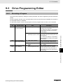
The following table shows the main functions of the Drive Programming Editor available in CX-Drive.
Function
Programming
Compilation
Transfer
Debugging support
1-2
Description
Supports the creation, editing, saving, reading, and printing of user programs.
Performs check of user programs and generates intermediate codes.
Downloads a user program to the inverter.
Uploads a user program from the inverter.
Starts and stops the execution of a program.
The user can check the inverter status monitor etc.
Drive Programming User’s Manual (I580-E2)
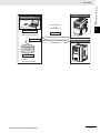
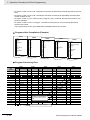
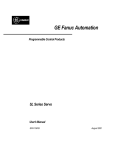
1 Overview
1-1 Overview of Drive Programming
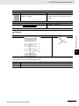
3G3MX2 Series Inverter
Monitoring software
CX-Drive
Ver. 2.7 or higher
Connect directly
or via
communications
(Drive Programming)
1
Programming
Creation, editing and
saving of user programs
Transmission
Upload
Compilation
Ver. 2.0 or later
3G3RX Series Inverter
Download
User Programs
Debugging support
Program execution
Monitor
Parameter changed
Drive Programming User’s Manual (I580-E2)
Ver. 2.0 or later
1-3
1 Overview
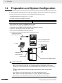
1-2
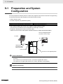
Preparation and System Configuration
You must prepare the following items to create user programs with functions of the Drive Programming
in CX-Drive and execute the programs in the 3G3MX2/3G3RX Series Inverter.
• 3G3MX2/3G3RX Series Inverter (Ver. 2.0 or later)
• Personal computer (PC) (Windows system)
32-bit PC
Windows XP SP3, Windows Vista, and Windows 7
64-bit PC
Windows Vista and Windows 7
• The CX-Drive requires the following versions.
MX2: Version 2.8 or higher for 3G3MX2 Series Inverter
RX: Version 2.7 or higher for 3G3RX Series Inverter
(The CX-Drive is included in the FA Integrated Tool Package, CX-One.)
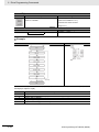
• Prepare the following PC-inverter connection cable.
MX2: Commercially-available USB cable (mini-B)
RX: USB to RJ-45 Converter Cable (Model: 3G3AX-PCACN2)
Commercially-available
USB cable (mini-B)
Remove the Digital Operator
(A) and the connector (B).
CX-Drive
(A)
USB
(B)
USB-RS422
Converter cable
3G3AX-PCACN2
RJ45 connector
Connector for the Digital Operator
Version Information
• Only the 3G3MX2/3G3RX Series Inverters have the Drive Programming function.
Be sure to check the version (Ver. 2.0 or later) printed on the nameplate of the inverter
because the conventional models of 3G3MX2/3G3RX Series Inverters do not have the function.
• The Drive Programming function is included in the following or higher versions of the
CX-Drive.
If the version of your CX-Drive is lower, you need to upgrade the version.
MX2: Version 2.8 or higher (with version 2.7 or lower, operation is not possible.)
RX: Version 2.7 or higher (with version 2.6 or lower, operation is not possible.)
1-4
Drive Programming User’s Manual (I580-E2)
1 Overview
For how to install or upgrade the CX-Drive, refer to the CX-Drive Operation Manual (W453).
EtherCAT/CompoNet/DeviceNet Communications
The CX-Drive can be connected to the inverter via communication through the Position Control Unit
(Model: CJ1W-NC82) of EtherCAT master, CompoNet Master Unit (Model:
CJ1W-CRM21/CS1W-CRM21), or DeviceNet Unit (Model: CJ1W-DRM21/CS1W-DRM21-V1) mounted
to the programmable controller.
To establish communication connection between the inverter and the CX-Drive through the programmable controller, you must configure the following settings in the CX-Drive in advance.
• Select properties of the drive project, and click [Settings] under [Drive Type] to set the option board
type to the inverter communication unit.
• Select properties of the drive project, and select the connection network under [Connection type].
Then, click [Settings] to set the network configuration under the [Network] and the connection method
to connect CX-Drive and PLC under [Gateway PLC].
Configuration
Communication Unit
EtherCAT Unit (Model: CJ1W-NC82)
CJ2 Series
Power supply unit
CPU Unit
CompoNet Master Unit (Model: CJ1W-CRM21)
DeviceNet Unit (Model: CJ1W-DRM21)
CX-Drive
RS-232C port connection
EtherCAT/CompoNet/DeviceNet
Peripheral (USB) port
connection
• For peripheral (USB) port connection, use commercially-available
USB cable.
• For peripheral port connection
Model: CS1W-CN226/-CN626
• For RS-232C port connection
Model: XW2Z-200S-CV/-500S-CV
Inverter
and EtherCAT Communication
Unit, CompoNet Communication Unit, or DeviceNet Communication Unit
Install the CX-Drive in your Windows personal computer. Connect the computer with the programmable
controller, and go online with the inverter via EtherCAT, CompoNet or DeviceNet communications.
When the online connection is established, you can use the Drive Programming Editor to create user
programs and transfer (download) them to the inverter.
Drive Programming User’s Manual (I580-E2)
1-5
1-2 Preparation and System
Configuration
Additional Information
1
1 Overview
1-6
Drive Programming User’s Manual (I580-E2)
2
Specifications
This section describes the specifications of the Drive Programming.
2-1 Specifications . . . . . . . . . . . . . . . . . . . . . . . . . . . . . . . . . . . . . . . . . . . . . . . . . 2-2
Drive Programming User’s Manual (I580-E2)
2-1
2 Specifications
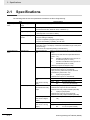
2-1
Specifications
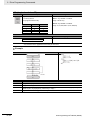
The following table shows the specifications related to the Drive Programming.
Program specifications
Item
Programming language
Input device
Program capacity
Programming support
function
Specifications
Flowchart and text language method
Windows personal computer
(OS: Windows XP-SP3, Windows Vista, or Windows 7)
1,024 steps max.: 6 KB
(1,024 steps max. for a total of 5 tasks)
Functions supported in Inverter/Servo support tool CX-Drive
• Program editing and display
• Program compilation (Program syntax check)
Execution format
• Program downloading, uploading, and all clear
• Execution by interpreter
• Execution cycle: 2 ms/step (5 commands executable through 5-task parallel processing)
Input/output functions
External input
• Subroutine call supported (Nesting in 8 levels max.)
Drive Programming
Select in the Drive Programming Function Selection
start
(A017)
Multi-function Input
Frequency reference
input
External output
(Multi-function analog
input)
Multi-function output/multi-function relay
output
Monitor output
(Multi-function digital
output)
Monitor output
(Multi-function analog
output)
2-2
• Start/stop via multi-function input PRG terminal
(A017 01)
MX2:
Allocate to the Multi-function Input S1 to
S7 Selection (C001 to C007).
RX:
Allocate to the Multi-function Input S1 to
S8 Selection (C001 to C008)
• Start/stop at power on/off (A01702)
MX2:
X(00) to X(07)/8 points
• Multi-function input S1 to S7 terminals
• X(07) is for the pulse train input RP terminal
(enabled only when P003 02)
RX:
X(00) to X(07)/8 points
• Multi-function input S1 to S8 terminals
XA(0):
0 to 10 V (FV terminal)
XA(1):
4 to 20 mA (FI terminal)
XA(2):
MX2:
No applicable function
RX:
10 to 10 V (FE terminal)
MX2:
Y(00) to Y(02)/3 points
• Multi-function output P1 and P2 terminals
• Multi-function relay output terminals (MA, MB)
RX:
Y(00) to Y(05)/6 points
• Multi-function output P1 to P5 terminals
• Multi-function relay output terminals (MA, MB)
YA(0):
PWM output in 6.4 ms cycle (MP terminal)
YA(1):
YA(2):
0 to 10 V (AM terminal)
MX2:
No applicable function
RX:
4 to 20 mA (AMI terminal)
Drive Programming User’s Manual (I580-E2)
2 Specifications
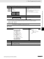
Commands
Item
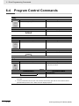
Program control commands
Specifications
• Loop ("for")
• Unconditional branch ("goto")
• Time control ("wait")
2-1 Specifications
• Conditional branch ("if then", "ifs then", "select case", "until", "while")
• Subroutine ("call", "sub")
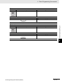
Arithmetic commands
• Others ("entry", "end", "inc", "dec")
• Four arithmetic operations (, , *, and /)
• Remainder ("mod") and assignment ()
• Absolute value ("abs")
I/O control
• Logical operations ("or", "and", "xor", "not")
• Multi-function I/O (bit input, word input, bit output, and word output)
2
• Reads inverter input terminals
Timer control
Parameter control
• Reads/writes inverter output terminals
Contacts control by timer and timer counter control
• Changes setting data of specified parameter number
• Saves parameter setting data in EEPROM
Inverter control
RX only: current time reading (once/continuous)
• Executes and stops forward/reverse operation
• Generates a trip by the Drive Programming (E50 to E59/10 points)
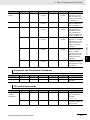
Function variable
User parameter variable
Internal user variable
Frequency reference
variable
Acceleration time variable
Deceleration time variable
Inverter monitor variable
Multi-function input
variable
• Frequency reference and acceleration/deceleration time settings
U(00) to U(31)/32 points
UL(00) to UL(07)/8 points
SET-Freq
ACCEL
DECEL
The monitor functions (d001 to d102) for the inverter are available as variables.
MX2 and RX:
FM, Iout, Dir, PID-FB, F-CNV, Tmon, Vout, Power, RUN-Time, ON-Time,
POS, STATUS, DCV, ERR-CNT, ERR(1) to ERR(6), and UMon(0) to
UMon(2)
The function options of the Multi-function Input S1 Selection (C001) for the
inverter are available.
MX2 and RX:
FW, RV, CF1, CF2, CF3, CF4, JG, DB, SET, TCH, FRS, EXT, USP, CS, SFT,
AT, RS, STA, STP, F-R, PID, PIDC, UP, DWN, UDC, OPE, SF1, SF2, SF3,
SF4, SF5, SF6, SF7, OLR, TL, TRQ1, TRQ2, BOK, LAC, PCLR, ADD, F-TM,
ATR, KHC, AHD, CP1, CP2, CP3, ORL, ORG, and SPD
MX2 only:
RS485, HLD, ROK, and DISP
RX only:
SET3, CAS, PPI, ORT, STAT, SON, FOC, FOT, ROT, PCNT, and PCC
Drive Programming User’s Manual (I580-E2)
2-3
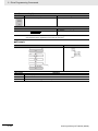
2 Specifications
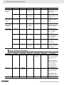
Function variable
Item
Multi-function output
variable
Specifications
The function options of the Multi-function Output P1 Selection (C021) for the
inverter are available.
MX2 and RX:
RUN, FA1, FA2, OL, OD, AL, FA3, OTQ, UV, TRQ, RNT, ONT, THM, BRK,
BER, ZS, DSE, POK, FA4, FA5, OL2, ODc, OIDc, FBV, NDc, LOG1, LOG2,
LOG3, WAC, WAF, FR, OHF, LOC, IRDY, FWR, RVR, MJA, WCO, and
WCOI
MX2 only:
FREF, REF, SETM, and EDM
RX only:
Input terminal variable
Output terminal variable
Internal user contact
Timer output contact
Timer counter variable
Analog input terminal
variable
Analog output terminal variable
2-4
IP, O2Dc, LOG4, LOG5, LOG6, and WCO2
MX2:
X(00) to X(07)/8 points
Note: X(07) is for the Pulse Train Input RP Selection (enabled only
when P003 02)
RX:
X(00) to X(07)/8 points
MX2:
Y(00) to Y(02)/3 points
RX:
Y(00) to Y(05)/6 points
UB(0) to UB(7)/8 points
TD(0) to TD(7)/8 points
TC(0) to TC(7)/8 points
MX2:
XA(0) and XA(1)
RX:
XA(0) to XA(2)
MX2:
YA(0) and YA(1)
RX:
YA(0) to YA(2)
Drive Programming User’s Manual (I580-E2)
Operation Procedure for Drive
Programming
3
This section describes the operation procedure of the Drive Programming, related
parameters, and program structures.
3-1 Operation Procedure . . . . . . . . . . . . . . . . . . . . . . . . . . . . . . . . . . . . . . . . . . . 3-2
3-2 Parameters Related to Drive Programming . . . . . . . . . . . . . . . . . . . . . . . . . 3-5
3-3 Program Structure . . . . . . . . . . . . . . . . . . . . . . . . . . . . . . . . . . . . . . . . . . . . 3-13
3-3-1
3-3-2
3-3-3
3-3-4
3-3-5
3-3-6
Drive Programming User’s Manual (I580-E2)
Tasks . . . . . . . . . . . . . . . . . . . . . . . . . . . . . . . . . . . . . . . . . . . . . . . . . . . . . . . .
Subroutines . . . . . . . . . . . . . . . . . . . . . . . . . . . . . . . . . . . . . . . . . . . . . . . . . . .
Task Processing . . . . . . . . . . . . . . . . . . . . . . . . . . . . . . . . . . . . . . . . . . . . . . .
Drive Programming Start/Stop and Task Operation . . . . . . . . . . . . . . . . . . . .
Drive Programming Restart . . . . . . . . . . . . . . . . . . . . . . . . . . . . . . . . . . . . . .
Task Operation on Trip . . . . . . . . . . . . . . . . . . . . . . . . . . . . . . . . . . . . . . . . . .
3-13
3-13
3-13
3-15
3-17
3-18
3-1
3 Operation Procedure for Drive Programming
3-1
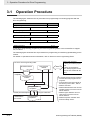
Operation Procedure
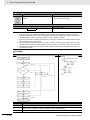
The following figure shows the flow of procedure from programming to executing programs with the
Drive Programming.
Item
Reference
P. 3-3
Programming
Compiling Programs
P. 3-3
Downloading Programs
P. 3-4
Selecting Drive Programming Functions
P. 3-4
Starting Programs
P. 3-4
Create Drive Programming programs by the Drive Programming Editor in the Inverter/Servo support
tool, CX-Drive.
The following figure shows the flow of procedure from programming to transferring (downloading) to the
inverter.
For details on operation and other information, refer to Section 4 Drive Programming Editor.
CX-Drive: Drive Programming Editor
Flowchart method
Text language
method
Convert
CX-Drive
compilation
Text language
method
Compilation
Programs after
compilation
Transfer (download/upload)
Programs
downloaded to
the inverter
3-2
Programs after
compilation
Upload
Program verification
Save
Saving user programs
• Saving as CX-Drive project
file
• Saving as exported file
Note: Saved programs are the
same as that created with the
Editor.
The compiler performs following operations:
• Converts flowchart programs to text
programs.
• Converts label names automatically to
the following names: label 1, label 2....
• Deletes comments.
• Deletes alias definitions and converts
specified names to the same ones as
before definition.
• Deletes region definitions and converts forms to the same ones as
before definition.
• Deletes all spaces and blank lines.
• Performs validity checks.
Drive Programming User’s Manual (I580-E2)
3 Operation Procedure for Drive Programming
Programming
You can create user programs in the flowchart method or the text language method. It is also possible
to select between two methods for each task or subroutine.
Use the Drive Programming Editor in CX-Drive to input user programs.
• In the Drive Programming area, you can create programs in the flowchart method or text language
method.
• The Toolbox window displays the command blocks in categories.
• In the Block Parameter window, you can set parameters that are used when the program execution is
started.
• In the Properties window, you can edit the properties of a block which is currently selected in flowchart.
• The Output window displays compilation errors and warnings after a compilation is finished.
Compiling Programs
Programs created in the Drive Programming area are compiled and converted into the final "programs
after compilation". Then, the programs are transferred (downloaded) to the inverter.
The compiler performs checks for the items such as program validity, program syntax, parameter input
limitation and maximum number of steps. If there is any input which is not permitted, the compilation is
stopped and an error message is displayed.
The compiler also performs the operations as shown below, and creates the final "programs after compilation". Therefore, if you transfer (upload) the program once saved in the inverter to the CX-Drive, the
program which is read out is the "program after compilation". While its operation is the same as before
compilation, its form and contents are partially different.
• Converts flowchart programs to text programs.
• Automatically converts the label names specified in the program to the following names: label 1, label
2...
• Deletes comments entered in the program.
• Deletes alias definitions and converts specified names to the same ones as before definition.
• Deletes region definitions and converts forms to the same ones as before definition.
• Deletes all spaces and blank lines in the program.
• Performs validity checks.
Precautions for Correct Use
• The specified comments, alias definitions and region definitions are deleted when a compilation is performed for program conversion or transferring (downloading) to the inverter.
To save those contents, save the program before you execute program conversion or you
transfer (download) the program to the inverter.
You can save the program by saving the whole project in the CX-Drive or export file of the
program.
• Program verification means a comparison between "program after compilation" and the program inside the inverter. Therefore, comments, alias definitions, region definitions, etc. are
not verified.
Drive Programming User’s Manual (I580-E2)
3-3
3-1 Operation Procedure
Drive Programming Editor consists of the Drive Programming area, Toolbox window, Block Parameter
window, Properties window, and Output window.
3
3 Operation Procedure for Drive Programming
Downloading Programs
Download compiled programs to the inverter and save them in the EEPROM of the inverter.
You can start programs saved in the EEPROM after turning on the power supply, without using the tool
(CX-Drive).
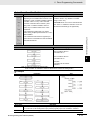
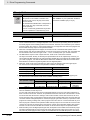
Selecting Drive Programming Functions
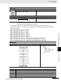
Set Drive Programming Function Selection (A017) to Enabled (01 or 02) to use the Drive Programming
function. You can change the Drive Programming Function Selection (A017) even when the operation is
in progress.
Parameter
No.
A017
Function name
Drive Programming
Function Selection
Data
Description
00: Disabled (default
setting)
01: Enabled
(Start/stop via
multi-function input
PRG terminal)
02: Enabled
(Start/stop at
power on/off)
Disables the Drive Programming function.
Programs are not executed.
If you change the setting to 00 (Disabled) during
program execution, the program will be stopped.
Starts the Drive Programming program when the
multi-function input terminal*1 which is set to 82
(PRG) is turned ON.
Starts the Drive Programming program automatically after the inverter power supply is turned on.
If you change the setting to 02 (Enabled) while the
program is stopped, the program will be started.
*1. Multi-function input terminals for MX2 are S1 to S7, and for RX are S1 to S8.
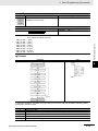
Starting Programs
When the Drive Programming Function Selection (A017) is set to 01 (Enabled: Start/stop via multi-function input PRG terminal), set one of Multi-function Input S1 to S7/S8 Selection to 82 (PRG). The program is started when the multi-function input terminal set to PRG is turned ON. The program execution
continues while the PRG terminal is ON and stops when the terminal is turned OFF.
When the Drive Programming Function Selection (A017) is set to 02, the program is started right after
the setting is completed. The program will also be started automatically at next power on.
Once the program reaches “end” command after it was started and a series of processes was completed, the program is not executed unless it is restarted.
To repeat the program, create a loop program so that the program does not reach “end” command.
The downloaded Drive Programming program is saved in the EEPROM of the inverter. Therefore, after
downloading, you can start the program without using the support tool.
Parameter
No.
C001 to
C007
C008
3-4
Function name
Data
Description
MX2 and RX:
Multi-function Input S1
to S7 Selection
RX only:
Multi-function Input S8
Selection
82: PRG
(Drive Programming start)
When the Drive Programming Function
Selection (A017) is set to 01 (Enabled:
Start/stop via multi-function input PRG
terminal), the program is started via the
multi-function input terminal with this setting.
Drive Programming User’s Manual (I580-E2)
3 Operation Procedure for Drive Programming
Parameters Related to Drive Programming
This section describes the inverter parameters that are related to the Drive Programming.
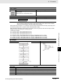
Selecting Drive Programming Functions
Set the Drive Programming Function Selection (A017) to Enabled (01 or 02) to use the Drive Programming function. You can change the Drive Programming Function Selection (A017) even when the operation is in progress.
Parameter
No.
A017
C001 to
C007
C008
Function name
Drive Programming
Function Selection
MX2 and RX:
Multi-function Input S1
to S7 Selection
RX only:
Multi-function Input S8
Selection
Data
3
Description
00: Disabled (default setting)
Disables the Drive Programming function.
Programs are not executed.
If you change the setting to 00 (Disabled)
during program execution, the program
will be stopped.
Starts the Drive Programming program
01: Enabled (Start/stop via
when the multi-function input terminal*1
multi-function input PRG
terminal)
which is set to 82 (PRG) is turned ON.
02: Enabled
Starts the Drive Programming program
(Start/stop at power on/off) automatically after the inverter power supply is turned on.
If you change the setting to 02 (Enabled)
while the program is stopped, the program
will be started.
82: PRG
When the Drive Programming Function
(Drive Programming start) Selection (A017) is set to 01 (Enabled:
Start/stop via multi-function input PRG terminal), the program is started via the
multi-function input terminal with this setting.
*1. Multi-function input terminals for MX2 are S1 to S7, and for RX are S1 to S8.
Initializing Programs
To initialize the Drive Programming program downloaded to the inverter, select 04 (Clear fault monitor +
initialize data + Clear Drive Programming) for the Initialization Selection (b084), and execute initialization by Initialization Execution (b180).
Parameter
No.
b084
b180
Function name
Initialization Selection
Initialization Execution
Drive Programming User’s Manual (I580-E2)
Data
04: Clear fault monitor + initialize
data + Clear Drive Programming
01: Execute initialization
3-2 Parameters Related to Drive Programming
3-2
Description
Select 04 to initialize the Drive Programming program as well.
Executes initialization of the selected
data.
3-5
3 Operation Procedure for Drive Programming
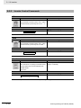
RUN Command Selection Setting
Use FW (forward) and RV (reverse) variables to control RUN commands through the Drive Programming
program. Be sure to set the RUN Command Selection (A002/A202) to 01 (Control circuit terminal block)
when you use FW or RV variable.
You can control through the program regardless of the setting 00 (FW: Forward) (for MX2 only) or 01
(RV: Reverse) in Multi-function Input Selection.
The relationship between the following items is OR:
MX2: The program's RUN command and the multi-function input terminal set to 00 (FW: Forward).
RX: The program's RUN command and the forward RUN command terminal FW and the multi-function
input terminal set to 01 (RV: Reverse).
MX2:
Parameter
No.
A002/
A202
1st/2nd RUN Command Selection
C001 to
C007
Multi-function Input
S1 to S7 Selection
Function name
Data
01: Control circuit terminal
block
(Drive Programming)
02: Digital Operator
03: Modbus communication
04: Option 1
05: Option 2
00: FW (Forward)
01: RV (Reverse)
Description
Select 01 (Control circuit terminal block) to
control the RUN command through the program with FW or RV variable.
If you select other setting, FW and RV variable are disabled.
The relationship between the program's
RUN command and the RUN command via
the control circuit terminal block is OR.
RX:
• Forward RUN command : the forward RUN command terminal FW (the relationship between the program's RUN command and the RUN command via the control circuit terminal block is OR.)
Parameter
No.
A002
C001 to
C008
3-6
Function name
RUN Command
Selection
Multi-function Input
S1 to S8 Selection
Data
01: Control circuit terminal
block
(Drive Programming)
02: Digital Operator
03: Modbus communication
04: Option 1
05: Option 2
01: RV (Reverse)
Description
Select 01 (Control circuit terminal block) to
control the RUN command through the program with FW or RV variable.
If you select other setting, FW and RV variable are disabled.
The relationship between the program's
RUN command and the RUN command via
the control circuit terminal block is OR.
Drive Programming User’s Manual (I580-E2)
3 Operation Procedure for Drive Programming
In the Drive Programming, you can use the inverter's I/O functions (multi-function I/O and analog I/O)
as the I/O functions of the program.
To use the I/O functions, it is necessary to set each I/O function according to the purpose.
This section describes how to set I/O functions for the Drive Programming.
By configuring the following settings, you can control I/O functions by the function variables of the Drive
Programming.
In the case that you use the functions for purpose other than Drive Programming I/O functions, refer to
the MX2 User's Manual (I570-E2) or the RX User's Manual (I560-E2).
MX2:
Parameter
No.
A001/
A201
1st/2nd Frequency
Reference Selection
07: Drive Programming
C001 to
C007
Multi-function Input
S1 to S7 Selection
56 to 62: MI1 to MI7
(General-purpose
input 1 to 7)
P003
Pulse Train Input RP
Selection
02: MI8
(General-purpose input 8
for Drive Programming)
C021
and
C022
C026
Multi-function Output
P1 and P2 Selection
44 to 46: MO1 to MO3
(General-purpose
output 1 to 3)
Function name
Data
C027
Multi-function Relay
Output (MA, MB)
Function Selection
MP Selection
C028
AM Selection
13: Drive Programming
(YA(1))
P031
Acceleration/Deceleration Time Input
Type
03: Drive Programming
Drive Programming User’s Manual (I580-E2)
12: Drive Programming
(YA(0))
3-2 Parameters Related to Drive Programming
Setting Inverter I/O Functions
Description
Use this setting to specify the inverter frequency reference by the function variables
of the Drive Programming.
If you select any other option than 01 (Control circuit terminal block), the analog inputs
(FV, FI) will be disconnected from the frequency reference and you can use them as
the analog inputs XA(00) and XA(01) for the
Drive Programming.
Set 56 to 62 (MI1 to MI7) to use the terminals for the general-purpose inputs for the
Drive Programming.
The parameter settings correspond to the
function variables X(00) to X(06).
Set 02: MI8 (General-purpose input 8 for
Drive Programming) to use the RP terminal
for the general-purpose input for the Drive
Programming.
The RP terminal corresponds to the function
variable X(07).
Set 44 to 46 (MO1 to MO3) to use the terminals for the general-purpose outputs for the
Drive Programming.
You can control the multi-function output terminals by changing the corresponding function variables Y(00) to Y(02) to ON/OFF.
Set 12 (Drive Programming) to use the terminal for the general-purpose pulse output
YA(0) for the Drive Programming.
Set 13 (Drive Programming) to use the terminal for the general-purpose analog output
(voltage) YA(1) for the Drive Programming.
Set this parameter to control the
acceleration/deceleration time through the
Drive Programming.
3-7
3
3 Operation Procedure for Drive Programming
Precautions for Correct Use
• Even if you select MI1 to MI7 (General-purpose input 1 to 7) for the Multi-function Input S1 to
S7 Selection, you can select NO (NO contact) or NC (NC contact) for the Multi-function Input
S1 to S7 Operation Selection (C011 to C017).
• Even if you select MO1 to MO3 (General-purpose output 1 to 3) for the Multi-function Output
P1 and P2 Selection or for the Multi-function Relay Output (MA, MB) Function Selection, you
can select NO (NO contact) or NC (NC contact) for the Multi-function Output P1 and P2 Operation Selection (C031, C032) or for the Multi-function Relay Output (MA, MB) Operation
Selection (C036).
• In the Drive Programming, the analog I/O functions are allocated to XA(0), XA(1), YA(0) and
YA(1). You can monitor the analog I/O status in the programs by using these function variables regardless of the settings for A001, A201, C027 and C028.
• In the Drive Programming programs, you cannot monitor the status of multi-function I/O terminals for which the general-purpose I/Os are not set in C001 to C007, C021, C022 or C026.
RX:
Parameter
No.
A001
3-8
Function name
Data
Frequency Reference Selection
07: Drive Programming
C001 to
C008
Multi-function Input
S1 to S8 Selection
56 to 63: MI1 to MI8
(General-purpose
input 1 to 8)
C021 to
C025
Multi-function Output
P1 to P5 Selection
44 to 49: MO1 to MO6
(General-purpose
output 1 to 6)
C026
Multi-function Relay
Output (MA, MB)
Function Selection
C027
MP Selection
12: Drive Programming
(YA(0))
C028
AM Selection
13: Drive Programming
(YA(1))
C029
AMI Selection
14: Drive Programming
(YA(2))
P031
Acceleration/Deceleration Time Input
Type
03: Drive Programming
Description
• Use this setting to specify the inverter frequency reference by the function variables
of the Drive Programming.
• If you select any other option than 01
(Control circuit terminal block), the analog
inputs (FV, FI, FE) will be disconnected
from the frequency reference and you can
use them as the analog inputs XA(00) to
XA(02) for the Drive Programming.
• Set 56 to 63 (MI1 to MI8) to use the terminals for the general-purpose inputs for the
Drive Programming.
• The parameter settings correspond to the
function variables X(00) to X(07).
• Set 44 to 49 (MO1 to MO6) to use the terminals for the general-purpose outputs for
the Drive Programming.
• You can control the multi-function output
terminals by changing the corresponding
function variables Y(00) to Y(05) to
ON/OFF.
Set 12 (Drive Programming) to use the terminal for the general-purpose pulse output
YA(0) for the Drive Programming.
Set 13 (Drive Programming) to use the terminal for the general-purpose analog output
(voltage) YA(1) for the Drive Programming.
Set 14 (Drive Programming) to use the terminal for the general-purpose pulse analog output (current) YA(2) for the Drive
Programming.
Set this parameter to control the
acceleration/deceleration time through the
Drive Programming.
Drive Programming User’s Manual (I580-E2)
3 Operation Procedure for Drive Programming
• Even if you select MI1 to MI8 (General-purpose input 1 to 8) for the Multi-function Input S1 to
S8 Selection, you can select NO (NO contact) or NC (NC contact) for the Multi-function Input
S1 to S8 Operation Selection (C011 to C018).
• Even if you select MO1 to MO6 (General-purpose output 1 to 6) for the Multi-function Output
P1 to P5 Selection or for the Multi-function Relay Output (MA, MB) Function Selection, you
can select NO (NO contact) or NC (NC contact) for the Multi-function Output P1 to P5 Operation Selection (C031 to C035) or for the Multi-function Relay Output (MA, MB) Operation
Selection (C036).
• If you enable the emergency shutoff function of the 3G3RX Series Inverter (SW1 ON), the
Multi-function Input S1 Selection (C001) will be set to 18 (RS) and the Multi-function Input S3
Selection (C003) will be set to 64 (EMR) automatically. In this condition, the Multi-function
Input S3/S4 Operation Selection (C011/C013) are fixed to NO (NO contact) and NC (NC contact) respectively and you cannot change them.
To allocate general-purpose inputs to Multi-function Input S1/S3 Selection, disable the emergency shutoff function.
• In the Drive Programming, the analog I/O functions are allocated to XA(0) to XA(2), and
YA(0) to YA(2). You can monitor the analog I/O status in the programs by using these function variables regardless of the settings for A001, C027 to C029.
• In the Drive Programming programs, you cannot monitor the status of multi-function I/O terminals for which the general-purpose I/Os are not set in C001 to C008 and C021 to C026.
Drive Programming User’s Manual (I580-E2)
3-9
3-2 Parameters Related to Drive Programming
Precautions for Correct Use
3
3 Operation Procedure for Drive Programming
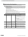
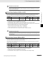
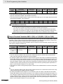
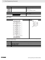
Monitor Function of Drive Programming
The following functions are provided to monitor the status of the Drive Programming.
Precautions for Correct Use
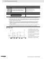
• For the data that exceeds four digits, the upper four digits of the data is displayed on the Digital Operator, as shown below.
A dot at the end of number represents the decimal point position. You can use this to figure
out the number of digits.
Display for data 0 to 9,999: 0. to 9999.
Display for data 10,000 to 65,535: 1000 to 6553
Display for data 1,230,000 and 1,230,000: 123 and 1230
• Since the Digital Operator displays only upper four digits, you cannot check or set lower digits
of data.
Use the CX-Drive to check or set the data that exceeds four digits.
Parameter
No.
d023
Function name
Program Counter
Data
0 to 1,024
(Drive Programming)
Description
Displays the line number of the program during the
Drive Programming execution.
The numbers that are displayed are the line numbers
of task 1 (the leftmost tab on the Drive Programming
Editor).
• The line numbers of the "program after compilation" are displayed.
• The number of line for which a subroutine execution is in progress is also displayed.
d024
Program Number Monitor 1
d025
(Drive Programming)
User Monitor 0
(Drive Programming)
d026
User Monitor 1
(Drive Programming)
d027
User Monitor 2
(Drive Programming)
3 - 10
2,147,483,647 to
2,147,483,647
2,147,483,647 to
2,147,483,647
2,147,483,647 to
2,147,483,647
Note: While program execution is stopped, "0000" is
displayed.
Displays the downloaded program number.
This monitor function corresponds to the function
variable UMon(0) and can display any data in the
program.
This monitor function corresponds to the function
variable UMon(1) and can display any data in the
program.
This monitor function corresponds to the function
variable UMon(2) and can display any data in the
program.
Drive Programming User’s Manual (I580-E2)
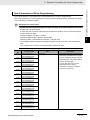
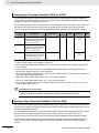
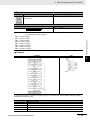
3 Operation Procedure for Drive Programming
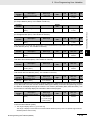
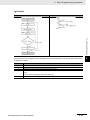
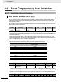
Up to 32 parameters are provided as the user parameters for the Drive Programming.
Use these parameters for various purposes such as program initial data setting, parameter for adjustment, and saving calculation results.
Precautions for Correct Use
• For the data that exceeds four digits, the upper four digits of the data is displayed on the Digital Operator, as shown below.
A dot at the end of number represents the decimal point position. You can use this to figure
out the number of digits.
Display for data 0 to 9,999: 0. to 9999.
Display for data 10,000 to 65,535: 1000 to 6553
3
Display for data 1,230,000 and 1,230,000: 123 and 1230
• As the Digital Operator displays only upper four digits, you cannot check or set lower digits of
data.
Use the CX-Drive to check or set the data that exceeds four digits.
Parameter
No.
P100
Drive Programming
P101
User Parameter U00
Drive Programming
P102
User Parameter U01
Drive Programming
P103
User Parameter U02
Drive Programming
P104
User Parameter U03
Drive Programming
P105
User Parameter U04
Drive Programming
P106
User Parameter U05
Drive Programming
P107
User Parameter U06
Drive Programming
P108
User Parameter U07
Drive Programming
P109
User Parameter U08
Drive Programming
P110
User Parameter U09
Drive Programming
P111
User Parameter U10
Drive Programming
P112
User Parameter U11
Drive Programming
P113
User Parameter U12
Drive Programming
Function name
Data
0 to 65,535
Description
• These user parameters correspond to
the function variables U(00) to U(28).
• You can change the data by using the
Digital Operator. The changed data is
saved in the EEPROM.
• The set data will be saved in the
EEPROM when the Write to
EEPROM command is executed in
the Drive Programming.
User Parameter U13
Drive Programming User’s Manual (I580-E2)
3-2 Parameters Related to Drive Programming
User Parameters of Drive Programming
3 - 11
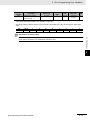
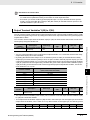
3 Operation Procedure for Drive Programming
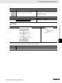
Parameter
No.
P114
Drive Programming
P115
User Parameter U14
Drive Programming
P116
User Parameter U15
Drive Programming
P117
User Parameter U16
Drive Programming
P118
User Parameter U17
Drive Programming
P119
User Parameter U18
Drive Programming
P120
User Parameter U19
Drive Programming
P121
User Parameter U20
Drive Programming
P122
User Parameter U21
Drive Programming
P123
User Parameter U22
Drive Programming
P124
User Parameter U23
Drive Programming
P125
User Parameter U24
Drive Programming
P126
User Parameter U25
Drive Programming
P127
User Parameter U26
Drive Programming
P128
User Parameter U27
Drive Programming
P129
User Parameter U28
Drive Programming
P130
User Parameter U29
Drive Programming
P131
User Parameter U30
Drive Programming
Function name
Data
0 to 65,535
Description
• These user parameters correspond to
the function variables U(00) to U(28).
• You can change the data by using the
Digital Operator. The changed data is
saved in the EEPROM.
• The set data will be saved in the
EEPROM when the Write to
EEPROM command is executed in
the Drive Programming.
User Parameter U31
3 - 12
Drive Programming User’s Manual (I580-E2)
3 Operation Procedure for Drive Programming
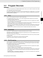
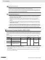
3-3
Program Structure
In the Drive Programming for 3G3MX2/3G3RX Series Inverter, you can create a maximum of five tasks.
The created tasks are processed in parallel.
3-3-1
Tasks
Task is a unit of program executed in the Drive Programming.
For 3G3MX2/3G3RX Series Inverter, you can create a program which consists of up to five tasks.
• All tasks are started simultaneously.
• All function variables such as user parameters are shared among the tasks. For transmission of information between tasks, use the user parameters, internal user contacts, etc.
• At the end of 2-ms processing time, the operation result of each task is reflected to the inverter operation, external output, etc. At the same time, the status of the inverter and external input terminals,
etc. are read in.
• When the "end" command is executed, the task is completed and waits for the next start.
3-3-2
Subroutines
Subroutine is a separated program processing executed only when it is called.
Subroutines are useful to organize your program into parts that you can execute multiple times in the
same task or reuse in other programs.
In the Drive Programming, it is necessary to insert subroutines into each task. They cannot be shared
among the tasks.
It is possible to call a subroutine from another subroutine (nesting).
However, the maximum nesting of subroutines is eight levels.
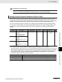
3-3-3
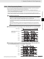
Task Processing
UP to five tasks are started simultaneously, and one command of each task (one line of the "program
after compilation") is executed in 2-ms processing time. The following figure Programs After Compilation (Example) shows the flow of the program processing.
• All tasks are started simultaneously.
• In the order of task from 1 to 5, one command of each task (one line of the "program after compilation") is executed in 2-ms processing time.
• All function variables such as user parameters are shared among the tasks.
• At the end of 2-ms processing time, the operation result of each task is reflected to the inverter operation, external output, etc. At the same time, the status of the inverter and external input terminals,
etc. are read in.
• As shown in Task 1, if a subroutine is called by the “call” command, the statement of the subroutine
will be executed from the next step of processing.
Drive Programming User’s Manual (I580-E2)
3 - 13
3
3-3-1 Tasks
• In the order of task from 1 to 5, one command of each task (one line of the "program after compilation") is executed in 2-ms processing time.
3-3 Program Structure
By dividing one application into several processes and allocating them to multiple tasks, you can adjust
execution condition, execution order, etc. for each process. Furthermore, parallel task processing can
provide shorter processing time.
3 Operation Procedure for Drive Programming
• As shown in Task 2, if the “end” command is executed, the task will be finished and wait for the next
start.
• As shown in Task 3, if the “wait” command is executed, the task will be repeatedly executed until a
certain condition is met.
• As shown in Task 4, if you create a loop by using the “goto” command, the task process will be continuously repeated.
• As shown in Task 5, if the “on trip goto” command is executed once, the processing data will be
stored in the inverter.
The program jumps to the “goto” destination immediately after a trip occurred.
Programs After Compilation (Example)
Task1
1
2
3
4
5
6
7
8
9
10
11
12
13
entry
label1
•••
call label2
•••
•••
•••
goto label1
end
sub label2
***
***
end sub
Task2
1
2
3
4
5
6
7
8
9
10
11
12
13
Task3
entry
•••
•••
•••
•••
•••
end
1
2
3
4
5
6
7
8
9
10
11
12
13
Task4
entry
wait 1 (0.01s)
•••
•••
•••
•••
end
1
2
3
4
5
6
7
8
9
10
11
12
13
Task5
entry
label1
•••
•••
•••
goto label1
end
1
2
3
4
5
6
7
8
9
10
11
12
13
entry
•••
on trip goto label2
label1
•••
•••
goto label1
label2
***
***
***
end
Program Processing Flow
Processing
time
[ms]
Task1
Line
No.
Task2
Line
No.
Task3
Line
No.
Task4
Line
No.
Task5
Line
No.
2
1
entry
1
entry
1
entry
1
entry
1
entry
4
2
label1
2
---
2
wait 1 (0.01s)
2
label1
2
---
6
3
---
3
---
2
wait 1 (0.01s)
3
---
3
on trip goto label2
8
4
call label2
4
---
2
wait 1 (0.01s)
4
---
4
label1 [Trip occurred]
10
10
sub label2
5
---
2
wait 1 (0.01s)
5
---
5
label2
12
11
***
6
---
2
wait 1 (0.01s)
6
goto label1
6
***
14
12
***
7
end
3
---
2
label1
7
***
16
13
end sub
4
---
3
---
2
***
18
5
---
5
---
4
---
3
end
20
6
---
6
---
5
---
8
22
7
---
7
end
6
goto label1
9
24
8
goto label1
2
label1
10
26
2
label1
3
---
11
28
3
---
4
---
12
30
4
call label2
5
---
32
10
sub label2
6
goto label1
34
11
***
36
12
38
13
Label2 is executed due to
occurrence of an inverter
trip.
2
label1
***
3
---
end sub
4
---
Program Counter (d023) display
3 - 14
Drive Programming User’s Manual (I580-E2)
3 Operation Procedure for Drive Programming
3-3-4
Drive Programming Start/Stop and Task Operation
You set the start/stop method of the Drive Programming programs in the Drive Programming Function
Selection (A017).
• When the Drive Programming Function Selection (A017) is set to 01 (Enabled: Start/stop via
multi-function input PRG terminal):
The program starts when the multi-function input terminal set to PRG is turned ON.
• When the Drive Programming Function Selection (A017) is set to 02 (Enabled: Start/stop at power
on/off):
The program starts when the power supply for the inverter is turned ON.
Stop
• When the Drive Programming Function Selection (A017) is set to 01 (Enabled: Start/stop via
multi-function input PRG terminal):
• When the Drive Programming Function Selection (A017) is set to 02 (Enabled: Start/stop at power
on/off):
The program stops when the power supply for the inverter is turned OFF.
Also, regardless of the A017 setting, the Drive Programming program stops if any of E43 to E45 trips is
detected due to a program error, or when the “end” command is executed in all tasks.
Precautions for Safe Use
When the Drive Programming program is stopped, the status before the program stop is
retained for multi-function outputs controlled by the Drive Programming
For this reason, configure the system so that the stop of the Drive Programming program in the
inverter can be detected by the Drive Programming start signal and the alarm (trip) signal, and
the inverter's peripheral devices can be stopped safely.
Precautions for Correct Use
The following are the status of function variables when the Drive Programming program is
stopped. Take necessary measures in consideration of each status.
• For the multi-function outputs (the inverter's actual output terminals), the status before the
program stop is retained.
However, the output terminals that are not set to MO1 to MO6 (general-purpose outputs of
the Drive Programming) operate as the inverter's normal multi-function outputs.
• When the Drive Programming function is selected for the frequency reference, acceleration/deceleration time or analog outputs, the set values for these functions before the program stop are retained.
• The data of the user parameter variables, internal user variables and internal user contacts
before the program stop is retained.
• The status of the inverter's actual input terminals such as the multi-function and analog input
terminals is not retained but always updated.
• The data of the multi-function output variables (function bits such as RUN, FA1 and AL) and
inverter monitor variables is not retained but always updated according to the status of the
inverter.
• Only the Drive Programming's multi-function input variables (function bits such as FW, RV
and CF1) and timer variables are cleared at the same time as the program stop, and all data
are changed to zero.
Drive Programming User’s Manual (I580-E2)
3 - 15
3
3-3-4 Drive Programming Start/Stop and Task Operation
The program stops when the multi-function input terminal set to PRG is turned OFF.
3-3 Program Structure
Start
3 Operation Procedure for Drive Programming
When the Drive Programming function is started/stopped through the CX-Drive, the value of the
inverter parameter, Drive Programming Function Selection (A017) is temporarily changed to 02
(start) or 00 (stop) only in the RAM data.
Take the following measures after you started/stopped the Drive Programming function through
the CX-Drive.
• Turn ON the power supply for the inverter again and return the value of A017 to that saved in
the EEPROM.
• Do not perform the following EEPROM saving operations before you turn ON the power supply for the inverter.
• Transferring (downloading) a part of parameters from the CX-Drive.
• Issuing the “enter” command via the Modbus communication or a communication option.
When the Drive Programming program is started, five tasks are started simultaneously.
If you create a loop construction in a task by using commands such as the “goto”, the task will repeat
the loop after it is started.
When the Drive Programming program is stopped, five tasks are stopped simultaneously.
If the program is stopped while the Motor is running, the Motor will be stopped according to the setting
for the Stop Selection (b091) (deceleration stop or free-run stop).
The task operations for different settings are shown below.
When the Drive Programming Function Selection (A017) is set to 01 (Enabled):
Power supply
Multi-function input terminal
MX2: S1 to S7
RX: S1 to S8
Power ON
PRG terminal ON
Power OFF
PRG terminal OFF
Task1
Start First
Stop
Task2
Start First
Stop
Task3
Start First
Task4
Start First
Task5
Start First
Stop
Stop
Stop
When the Drive Programming Function Selection (A017) is set to 02 (Enabled):
Power supply
Task1
Task2
Task3
Task4
Task5
3 - 16
Power ON
Power OFF
Start First
Stop
Start First
Stop
Start First
Start First
Start First
Stop
Stop
Stop
Drive Programming User’s Manual (I580-E2)
3 Operation Procedure for Drive Programming
3-3-5
Drive Programming Restart
You can restart the stopped program by performing the following operations. When the program is
restarted, all tasks are started simultaneously from the beginning.
• When the Drive Programming Function Selection (A017) is set to 02 (Enabled: Start/stop at power
on/off): a reset input via the control circuit terminal, or turning ON the power supply for the inverter again.
Precautions for Correct Use
• You cannot restart the Drive Programming by pressing the STOP/RESET key of the Digital
Operator or the LCD Digital Operator (optional). Set one of the Multi-function input terminals
(MX2: S1 to S7/RX: S1 to S8) to 18 (RS: Reset) and turn ON that terminal.
• When the Reset Selection (C102) is set to 00 (Trip reset at power-on) or 01 (Trip reset at
power-off), the Drive Programming can be restarted by a reset input even when there is no
trip.
Restart when the Drive Programming Function Selection (A017) is set to 01 (Enabled):
Power supply
Multi-function input terminal
MX2: S1 to S7
RX: S1 to S8
Task1
Task2
Task3
Task4
Task5
Power ON
Power OFF
PRG terminal
ON
PRG terminal OFF PRG terminal
ON
Stop
Start
PRG terminal OFF
Stop
Start
First
First
Stop
Start
Stop
Start
First
First
Stop
Start
Stop
Start
First
First
Stop
Start
Start
First
Stop
First
Stop
Start
Stop
Start
First
First
Restart after trip when the Drive Programming Function Selection (A017) is
set to 02 (Enabled) (without “on trip goto” command):
Power ON
Trip
Trip reset
Power OFF
Power supply
Task1
Task2
Task3
Stop
Start
Start
Stop
Start
Stop
Start
Stop
First
Stop
First
Stop
First
First
Start
Drive Programming User’s Manual (I580-E2)
First
First
Task4
Stop
Start
First
Start
Task5
First
Stop
Start
Stop
Start
First
Stop
Start
First
3 - 17
3
3-3-5 Drive Programming Restart
• To restart the Drive Programming by reset input, set the Reset Selection (C102) to the value
other than 03 (Trip reset only). You cannot restart the Drive Programming when 03 (Trip reset
only) is set.
3-3 Program Structure
• When the Drive Programming Function Selection (A017) is set to 01 (Enabled: Start/stop via
multi-function input PRG terminal): a reset input via the control circuit terminal while the PRG terminal
is ON, or turning ON the PRG terminal again.
3 Operation Procedure for Drive Programming
3-3-6
Task Operation on Trip
Basically, even if the inverter detects a trip during the Drive Programming operation, the operation is
continued. However, if any of E43 to E45 trips related to the Drive Programming is detected, the operation is stopped.
Or, with the “on trip goto” command, the program can jump to other process after a trip occurred.
With/without
“on trip goto”
Without
With
User trip
E50 to E59
Operation is continued.
After the “on trip goto”
command is executed, the
program jumps to the
specified label and the
operation is continued.
Error status
Drive Programming
related trip E43 to E45
Program is stopped.
Program is stopped.
Other trips
Operation is continued.
After the “on trip goto”
command is executed, the
program jumps to the
specified label and the
operation is continued.
For details on the trips E43 to E59, refer to Section 8 Errors and Remedies.
3 - 18
Drive Programming User’s Manual (I580-E2)
Drive Programming Editor
This section describes how to start the Drive Programming Editor, saving and loading
data, and details on parts of the Editor.
4-1 Starting Drive Programming Editor . . . . . . . . . . . . . . . . . . . . . . . . . . . . . . . 4-2
4-2 Parts of Drive Programming Editor . . . . . . . . . . . . . . . . . . . . . . . . . . . . . . . 4-6
4-2-1
4-2-2
4-2-3
4-2-4
4-2-5
4-2-6
4-2-7
Drive Programming Editor . . . . . . . . . . . . . . . . . . . . . . . . . . . . . . . . . . . . . . . . 4-6
Toolbar . . . . . . . . . . . . . . . . . . . . . . . . . . . . . . . . . . . . . . . . . . . . . . . . . . . . . . . 4-6
Drive Programming Area . . . . . . . . . . . . . . . . . . . . . . . . . . . . . . . . . . . . . . . . . 4-9
Toolbox Window . . . . . . . . . . . . . . . . . . . . . . . . . . . . . . . . . . . . . . . . . . . . . . . 4-13
Block Parameters Window . . . . . . . . . . . . . . . . . . . . . . . . . . . . . . . . . . . . . . . 4-14
Properties Window . . . . . . . . . . . . . . . . . . . . . . . . . . . . . . . . . . . . . . . . . . . . . 4-15
Error List Tab in Output Window . . . . . . . . . . . . . . . . . . . . . . . . . . . . . . . . . . . 4-16
4-3 Adding, Deleting and Renaming Tasks . . . . . . . . . . . . . . . . . . . . . . . . . . . 4-17
4-4 Inserting, Deleting and Calling Subroutines . . . . . . . . . . . . . . . . . . . . . . . 4-18
4-5 Creating Flowchart Programs . . . . . . . . . . . . . . . . . . . . . . . . . . . . . . . . . . . 4-19
4-6 Creating Text Programs . . . . . . . . . . . . . . . . . . . . . . . . . . . . . . . . . . . . . . . . 4-20
4-7 Editing Transferred (Uploaded) Programs . . . . . . . . . . . . . . . . . . . . . . . . . 4-21
4-8 Saving Programs . . . . . . . . . . . . . . . . . . . . . . . . . . . . . . . . . . . . . . . . . . . . . 4-22
4-9 Transferring and Verifying Programs . . . . . . . . . . . . . . . . . . . . . . . . . . . . . 4-24
4-10 Executing Programs (Drive Programming Function Selection) . . . . . . . 4-25
4-11 Other Useful Functions . . . . . . . . . . . . . . . . . . . . . . . . . . . . . . . . . . . . . . . . 4-28
Drive Programming User’s Manual (I580-E2)
4-1
4
4 Drive Programming Editor
4-1
Starting Drive Programming Editor
To create Drive Programming programs, you use the Drive Programming Editor in the support tool for
the Inverter/Servomotor, CX-Drive.
This section explains the configuration of the Drive Programming Editor in the CX-Drive and the operations you carry out before starting the Drive Programming Editor.
Precautions for Correct Use
• The Drive Programming function is included in the following or higher versions of the CX-Drive.
If the version of your CX-Drive is lower, you need to upgrade the version.
MX2: Version 2.8 or higher (with version 2.7 or lower, operation is not possible.)
RX: Version 2.7 or higher (with version 2.6 or lower, operation is not possible.)
• A password is required when you start the Drive Programming Editor in the CX-Drive for the
first time.
Please contact your OMRON representative.
CX-Drive and Drive Programming Editor Screen Layout
The Drive Programming Editor is included as one of the functions of the support tool for the
Inverter/Servomotor, CX-Drive. When the Drive Programming Editor is started, the screen layout of the
CX-Drive will be changed as shown below.
Workspace
Drive Programming area
Toolbar
Block Parameters
window
Properties window
Toolbox window
Status bar
4-2
Error List tab
Output window
Drive Programming User’s Manual (I580-E2)
4 Drive Programming Editor
Starting CX-Drive
Use the following method to start the CX-Drive: from the Windows [Start] Menu, select [All Programs] [OMRON] - [CX-One] - [CX-Drive]. Click the CX-Drive icon in the CX-Drive folder.
Select 3G3MX2 or 3G3RX series from the pull-down list under the [Drive Type]. Click the [Settings] button to the right.
In the [Drive Type Settings] dialog box, set [Installation Type/Option], [Voltage Class], and [Maximum
Motor Capacity].
After setting these items, click the [OK] button to close the [Drive Type Settings] dialog box.
4-1 Starting Drive Programming Editor
After the CX-Drive is started, select [File] from the CX-Drive Menu and click [New] to create a new
CX-Drive file. The [New Drive] dialog box will appear.
4
Drive Programming User’s Manual (I580-E2)
4-3
4 Drive Programming Editor
In the [New Drive] dialog box, you set the connection type for the CX-Drive and the inverter.
Under the [Connection Type], select [Direct] and click the [Settings] button to the right.
On the [Driver] tab page, set the [Port Selection] to the port name of the computer on which the
CX-Drive is installed.
After setting these items, click the [OK] button and close all dialog boxes. The new project is registered
in the workspace.
4-4
Drive Programming User’s Manual (I580-E2)
4 Drive Programming Editor
Starting Drive Programming Editor
There are three ways to display the Drive Programming Editor:
• Double click the [Drive Programming] in the workspace.
4-1 Starting Drive Programming Editor
• Click
button on the CX-Drive toolbar.
• From the [Drive] Menu, select [Program] - [Program Editor].
4
Precautions for Correct Use
To start the Drive Programming Editor for the first time after you started the CX-Drive, a password is required.
Please contact with your sales representative to request the access code, and enter it in the following dialog box.
Drive Programming User’s Manual (I580-E2)
4-5
4 Drive Programming Editor
4-2
Parts of Drive Programming Editor
This section provides the detailed information on each function of the Editor and windows related to the
Drive Programming in the CX-Drive.
4-2-1
Drive Programming Editor
The Drive Programming Editor is the main widow for the Drive Programming function.
Toolbar
Drive Programming area
This window consists of the toolbar in which common commands are included and the Drive Programming area in which the program is displayed as text or flowchart.
4-2-2
Toolbar
The Drive Programming Editor provides the following commands:
Common commands
Command
New Task (flowchart)
4-6
Icon
Description
Creates a new flowchart task for the program. Task is a unit of
program executed in the Drive Programming.
New Task (text)
Creates a new text task for the program. Task is a unit of program executed in the Drive Programming.
New Subroutine (flowchart)
Creates a new flowchart subroutine. A subroutine is a part of
the program which is executed only when it is called.
New Subroutine (text)
Creates a new text subroutine. A subroutine is a part of the
program which is executed only when it is called.
Rename Current Task
Renames the current task or subroutine.
Delete Current Task
Deletes the current task or subroutine.
Undo
Undoes the latest change.
Redo
Redoes the undone operation.
Drive Programming User’s Manual (I580-E2)
4 Drive Programming Editor
Command
Transfer to Drive
Icon
Description
Compiles the program and, if there are no errors, transfers
(downloads) it to the drive (inverter).
Compile
Set Password
Compiles the program in the Drive Programming area.
Compile errors and warnings that occurred in the program will
be displayed on the Error List tab page in the Output window.
Starts the program in the inverter. The CX-Drive will first
compare the program in the inverter with the program in the
Drive Programming area. The program will be started only
when they are the same. If they differ, the program will not be
started.
This starting method for the program is enabled only when the
CX-Drive is connected.
To start the program with a stand-alone inverter, be sure to set
the Drive Programming Function Selection (A017).
Stops the program in the inverter. This operation is performed
independently of the program on the Drive Programming area
in the CX-Drive.
Sets a program number from 0 to 9,999. After the program is
transferred (downloaded) to the drive (inverter), the program
number is updated and you can see that by the Program Number Monitor (Drive Programming) (d024).
Enables to set, change or delete the program password.
Help
Displays the CX-Drive help.
Start
Stop
Set Program Number
Commands for the flowchart program
Command
Zoom in
Icon
Description
Increases the zoom level.
Zoom out
Decreases the zoom level.
Zoom Reset
Restores the zoom to its initial value.
Select Mode
Selects one or more blocks*1 of the program by dragging with
the mouse cursor.
Pan Mode
By dragging, moves the field of the view in any direction while
keeping the same scale.
Horizontal Align Left
Aligns horizontally the left sides of the currently selected
blocks*1.
Horizontal Align Middle
Aligns horizontally the middles of the currently selected
blocks*1.
Horizontal Align Right
Aligns horizontally the right sides of the currently selected
blocks*1.
Vertical Align Top
Aligns vertically the top sides of the currently selected
blocks*1.
Vertical Align Middle
Drive Programming User’s Manual (I580-E2)
Aligns vertically the middles of the currently selected blocks*1.
4-7
4
4-2-2 Toolbar
Transfers (uploads) the program from the drive (inverter) to
the Drive Programming Editor.
4-2 Parts of Drive Programming Editor
Transfer from Drive
4 Drive Programming Editor
Command
Vertical Align Bottom
Icon
Description
Aligns vertically the bottoms of the currently selected blocks*1.
Orientation
Selects an orientation for connecting the blocks*1.
Auto-arrange
Arranges the blocks*1 of the flowchart automatically in the currently selected orientation.
Show Contacts
Switches display/hide of the contacts of the blocks*1.
Show
Enables to select a display style of the program from options
below.
• Text only
• Icon only
• Icon and text
• Name, icon and arguments
*1. A unit of display on the flowchart is called "Block". A block consists of a command, or a command and a label
attached to the command.
Commands for the text program
Command
Icon
Find
Description
Looks for a text in the Drive Programming Editor.
Replace
Replaces a text in the Drive Programming Editor.
Increment Indentation
Increases the indentation of the selected text.
Decrement Indentation
Decreases the indentation of the selected text.
Format selected text
Formats automatically the selected text.
Comment selected text
Transforms the selected lines of text to comments.
Uncomment selected text
Uncomments the selected lines of text.
Program conversion
You can convert a flowchart program to a text program, and vice versa.
When a conversion is performed, the program is once compiled. Note that if a compilation error
occurs, the conversion will not be completed.
Also, comments, alias definition, region definition, etc. are deleted when a compilation is performed
for conversion. The operation does not change, however, the forms and contents of the program are
partially changed.
Command
Convert Text to Flowchart
Convert whole program to
Flowchart
4-8
Icon
Description
Converts current text task/subroutine to flowchart.
Converts whole program to flowchart.
Drive Programming User’s Manual (I580-E2)
4 Drive Programming Editor
Command
Convert Flowchart to Text
Icon
Convert whole program to
Text
Description
Converts current flowchart task/subroutine to text.
Converts whole program to text.
4-2 Parts of Drive Programming Editor
Shortcut keys
You can use the following keyboard shortcuts in the Drive Programming area.
Shortcut
4-2-3
Description
Cut
Copy
Paste
Undo
Redo
Select all
Find and replace
Command list
Select next (flowchart only)
Move selected block
Scroll to top (flowchart only)
Scroll to bottom (flowchart only)
Move the cursor to line head
Move the cursor to end of the line
Zoom in
Zoom out
4
4-2-3 Drive Programming Area
Ctrl X
Ctrl C
Ctrl V
Ctrl Z
Ctrl Y
Ctrl A
Ctrl F
Ctrl space
Tab
Arrow Keys
Home
End
Page Up
Page Down
Drive Programming Area
The Drive Programming area displays the current design of the program.
This area may have different pages, organized in tabs. Each tab is either a task or a subroutine in flowchart or text.
By right-clicking the tab title, you can delete or rename a task or a subroutine.
Drive Programming User’s Manual (I580-E2)
4-9
4 Drive Programming Editor
Flowchart Program
In the flowchart program method, a unit of display is called "Block".
You create a program by placing more than one block in the area and setting interaction between them.
In a flowchart program, when a program is compiled successfully, an icon with a white arrow in a green
circle highlights the starting point of each flowchart task.
Also, after the program is compiled successfully, the block number will appear on the upper left of each
block.
Block numbers are the consecutive numbers starting with "0". A block number is given to each block of
the whole program.
The numbers do not match the line numbers of the program converted to text.
The Output window will indicate if the program is compiled successfully. For programs compiled with
errors, a red icon with an exclamation mark identifies the erroneous blocks in the flowchart program.
Placing the mouse on the error icon displays the compile error, which you can see in the Error List in
the Output window.
If you right-click on a blank area in the flowchart, a popup menu will be displayed. It allows you to paste
blocks that you copied last, or to select all the blocks.
4 - 10
Drive Programming User’s Manual (I580-E2)
4 Drive Programming Editor
If you right-click on a flowchart block, a popup menu with more options will appear.
4-2 Parts of Drive Programming Editor
4
The following table shows the menu commands available in the flowchart program.
[Lock]
[Cut]
[Copy]
[Paste]
[Set Label]
[Set Subroutine]
Description
Places the selected block graphically in front of other blocks.
Places the selected block graphically in back of other blocks.
Fixes the selected block to its current position in the graph. It will not be moved in
drag operations.
Acts like [Pin] and, besides, sets the properties of the block as read-only.
Deletes the selected block and saves it in the clipboard, for further pasting.
Saves the selected block in the clipboard, for further pasting.
Puts the contents previously copied in the clipboard into the design area. Note that
you can also paste them as images in other applications.
Sets the label name for the selected block.
Sets the subroutine name for the selected block. This menu command is available
only for blocks for which you can set subroutines.
Drive Programming User’s Manual (I580-E2)
4 - 11
4-2-3 Drive Programming Area
Command
[Bring To Front]
[Send To Back]
[Pin]
4 Drive Programming Editor
Text Program
In the text program method, you create a program by using text language.
For text programs that were not compiled successfully, the program errors will be displayed in the Output window. The statement with errors will be highlighted with a red line.
Right-click the selected text to display a popup menu.
The following table shows the menu commands available in the text program.
Command
[Find]
[Replace]
[Cut]
[Copy]
[Paste]
[Go to Subroutine]
[Go to Label]
[Undo]
[Redo]
[Help]
4 - 12
Description
Looks for the selected text on the program code.
Replaces the selected text on the program code.
Deletes the selected text and saves it in the clipboard, for further pasting.
Saves the selected text in the clipboard, for further pasting.
Puts the contents previously copied in the clipboard into the design area. Note that
you can also paste them as images in other applications.
Jumps to the selected text subroutine.
Jumps to the selected text label.
Undoes the latest change.
Redoes the undone operation.
Displays the CX-Drive help.
Drive Programming User’s Manual (I580-E2)
4 Drive Programming Editor
4-2-4
Toolbox Window
The Toolbox window allows you to add blocks to the Drive Programming area by drag and drop. It displays the blocks supported for a particular command, organized in categories.
The Toolbox window is displayed by default at the right side of the CX-Drive.
You can separate the window by double-clicking the title bar (wide frame of the window).
4-2 Parts of Drive Programming Editor
The Toolbox is displayed when the Drive Programming Editor is started. You can also show or hide it by
clicking [Drive Programming] - [Toolbox] in the [View] Menu.
4
4-2-4 Toolbox Window
You can also select its display style by right-clicking on it with the mouse. Three styles are available:
large icons, small icons, and list. In any style, a short help text will be shown when you place the mouse
cursor on a block.
Click on any category title to display the blocks which belong to that category.
Drive Programming User’s Manual (I580-E2)
4 - 13
4 Drive Programming Editor
4-2-5
Block Parameters Window
The Block Parameters window allows you to edit Drive Programming user parameters which act as
variables of the program. The displayed parameters are organized in categories.
The Block Parameters is displayed when the Drive Programming Editor is started. You can also show
or hide it by clicking [Drive Programming] - [Block Parameters] in the [View] Menu.
The Block Parameters window is displayed by default at the right side of the CX-Drive.
You can separate the window by double-clicking the title bar (wide frame of the window).
To change the value of a parameter, place the cursor at its row and click on the edition box to the right
of its number. Enter the new value. A warning will be displayed if the entered value exceeds the valid
range.
At the lower part of the window, a help text for the user parameters is displayed.
4 - 14
Drive Programming User’s Manual (I580-E2)
4 Drive Programming Editor
4-2-6
Properties Window
The Properties window allows you to edit the properties of the block which is currently selected in the
flowchart program.
The Properties window is displayed by default at the right side of the CX-Drive.
You can separate the window by double-clicking the title bar (wide frame of the window).
4-2 Parts of Drive Programming Editor
The Properties is displayed when the Drive Programming Editor is started. You can also show or hide it
by clicking [Drive Programming] - [Properties] in the [View] Menu.
4
4-2-6 Properties Window
To change one block command argument, select the block in the flowchart and place the cursor on the
section where you want to edit in the Properties window.
• If the block argument has options, click on the current value to display
Click
icon at the rightmost side.
or double-click the current value to unfold the available options in the pulldown menu.
• If the block argument does not have options, click its current value and enter the new one to change
the value. A warning will be displayed if the entered value exceeds the valid range.
• If the block argument can have both an option and a custom value, you can set a value directly by
clicking the current value. Also, double-clicking the current value will unfold the available options in
the pulldown menu.
Drive Programming User’s Manual (I580-E2)
4 - 15
4 Drive Programming Editor
4-2-7
Error List Tab in Output Window
The list of errors related to the Drive Programming is displayed when you click the Error List tab in the
Output window.
The error list shows the compilation errors and warnings of the program currently created with the Drive
Programming Editor after it is compiled.
If any compilation errors is shown, the program is not correctly compiled.
In this case, transferring to the inverter or converting between flowchart and text is not performed.
Even in the case of successful compilation, warnings may be displayed to show points to correct in the
program.
The error list is updated automatically every time a compilation is completed, and fixed errors and warnings are cleared.
The Output window is displayed by default at the bottom of the CX-Drive.
You can separate the window by double-clicking the title bar (wide frame of the window).
[Errors] button switches the display of errors in the list.
[Warnings] button switches the display of warnings in the list.
[Messages] button switches the display of informative messages in the list.
The messages in the list contain the following information:
Information
Date
Component
Name
4 - 16
Description
Shows the date and time when the error occurred.
Identifies the block with an error.
Shows names or descriptions of the error or warning message.
Drive Programming User’s Manual (I580-E2)
4 Drive Programming Editor
4-3
Adding, Deleting and Renaming Tasks
To add a new task, select [New Tab] in the toolbar of the Drive Programming Editor,
and select [New Task (flowchart)] or [New Task (text)].
A new task appears on the Drive Programming Editor.
Among the displayed tasks, the task which is closer to the leftmost side takes higher priority in processing in a 2-ms period.
All tasks must begin with "entry" command, and finish with "end" command.
Flowchart
Text
4-3 Adding, Deleting and Renaming Tasks
The Drive Programming Editor will display an empty task by default when it is started from the
CX-Drive.
4
You can delete or rename the selected task by right-clicking on its tab in the Drive Programming Editor.
Drive Programming User’s Manual (I580-E2)
4 - 17
4 Drive Programming Editor
4-4
Inserting, Deleting and Calling Subroutines
To insert a subroutine, select the tab of the task in which you want to insert a subroutine, and select [New
Tab] - [New Subroutine (flowchart)] or [New Subroutine (text)] in the toolbar of the Drive Programming
Editor.
A new subroutine appears on the Drive Programming Editor.
Similar to tasks, you can delete or rename a subroutine by right-clicking on its tab.
The subroutine name is displayed as "Task name: Subroutine name", next to the task name to which
the subroutine belongs.
All subroutines must begin with "sub" command, and finish with "endsub" command.
Flowchart
Text
To execute a subroutine, specify the subroutine name in the "call" command.
It is only possible to call a subroutine that belongs to the task. Tasks cannot share the same subroutine.
To use a subroutine with multiple tasks, insert the same subroutine in each task.
Flowchart
4 - 18
Text
Drive Programming User’s Manual (I580-E2)
4 Drive Programming Editor
4-5
Creating Flowchart Programs
When you create a Drive Programming program, you can select flowchart or text for each task or subroutine.
1
Open the Drive Programming Editor.
The Drive Programming auxiliary windows (Toolbox, Block Parameters, Properties and Error
List tab) are displayed automatically.
2
3
From [New Tab] in the toolbar, select [New Task (flowchart)] or [New Subroutine (flowchart)].
Select commands from the Toolbox window and move them to the Drive Programming Editor by
drag-and-drop.
On the upper left of each block placed on the Editor, the block number will appear after the compilation is finished.
Block numbers are the consecutive numbers starting with "0". A block number is given to each
block of the whole program.
Block numbers do not match the line numbers of the program converted to text.
4
Click the block to edit its properties.
In the Properties window, edit arguments that are associated with the block.
5
Connect the blocks according to the program sequence.
You can connect a block with another by dragging from one's orange-colored contact to
another's green-colored contact.
6
7
Edit user parameters in the Block Parameters window.
Perform operations such as program compilation, transferring to the inverter, and data saving.
Execute compilation and check for any compilation errors in the program.
You can transfer the program to the inverter when the compilation is finished successfully.
To save the program, save the whole project. Or, you can save the program separately by using
the function that exports programs.
Drive Programming User’s Manual (I580-E2)
4 - 19
4-5 Creating Flowchart Programs
Follow the steps described below to create a flowchart program.
4
4 Drive Programming Editor
4-6
Creating Text Programs
When you create a Drive Programming program, you can select flowchart or text for each task or subroutine.
Follow the steps described below to create a text program.
1
Open the Drive Programming Editor.
The Drive Programming auxiliary windows (Toolbox, Block Parameters, Properties and Error
List tab) are displayed automatically.
2
3
From [New Tab] in the toolbar, select [New Task (text)] or [New Subroutine (text)].
There are three ways to edit text program codes:
• Manual typing
• Calling the text command list (Ctrl space)
• Dragging and dropping commands from Toolbox window
4
Set arguments of each command.
The required arguments are displayed with a green background for the commands that are
dragged and dropped from the Toolbox window and the commands selected from the text command list (Ctrl space).
Set each argument to complete the command.
Each time you edit a command by manual typing, the popup support will appear to help you
complete the command. For details on each command, refer to Section 6 Drive Programming
Commands.
You need not care about unnecessary lines and spaces when creating a program because they
will be deleted by program compilation.
5
Perform operations such as program compilation, transferring to the inverter, and data saving.
Execute compilation and check for any compilation errors in the program.
You can transfer the program to the inverter when the compilation is finished successfully.
To save the program, save the whole project. Or, you can save the program separately by using
the function that exports programs.
4 - 20
Drive Programming User’s Manual (I580-E2)
4 Drive Programming Editor
4-7
Editing Transferred (Uploaded) Programs
Follow the steps described below to edit the program.
1
Open the Drive Programming Editor.
The Drive Programming auxiliary windows (Toolbox, Block Parameters and Properties) are displayed automatically.
2
3
Go online with the CX-Drive. From the Menu, select [Drive] - [Work Online]. Or, click the [Work
Online] icon in the CX-Drive toolbar.
Click the [Transfer from Drive] icon in the toolbar of the Drive Programming Editor.
A program is transferred from the drive (inverter) and automatically displayed in the Drive
Programming area of the Drive Programming Editor.
4
Edit the transferred (uploaded) program.
4
"Programs after compilation" are downloaded to the inverter.
Therefore, the transferred (uploaded) program will be displayed as a text program.
To display it as a flowchart program, click [Convert whole program to Flowchart] in the toolbar of
the Drive Programming Editor and convert the program to flowchart.
5
4-7 Editing Transferred (Uploaded) Programs
You can edit the program which is transferred (uploaded) from the inverter.
Perform operations such as program compilation, transferring to the inverter, and data saving.
Execute compilation and check for any compilation errors in the program.
You can transfer the program to the inverter when the compilation is finished successfully.
To save the program, save the whole project. Or, you can save the program separately by using
the function that exports programs.
When the Drive Programming programs exist, you can transfer them to/from the inverter by using
[Transfer to Drive] or [Transfer from Drive] icon in the CX-Drive toolbar. In this case, you need to select
"programs" when a message dialog appears and asks you whether to transfer the parameters, programs, or both.
Drive Programming User’s Manual (I580-E2)
4 - 21
4 Drive Programming Editor
4-8
Saving Programs
There are two ways to save programs created with the Drive Programming function as described below.
Select a way suitable for your purpose.
Saving whole CX-Drive project
By saving the whole project created with the CX-Drive, you can save all drive data including the Drive
Programming program.
Click [File] in the Menu bar, select [Save As] and enter the file name.
When a saved project is opened, the Drive Programming program included in the project is automatically loaded.
You can display the program by double-clicking the Drive Programming in the Workspace and start the
Drive Programming Editor.
4 - 22
Drive Programming User’s Manual (I580-E2)
4 Drive Programming Editor
Saving Dive Programming program by export
You can save a Drive Programming program separately.
Click [Drive] in the Menu bar, select [Program] - [Export Program] and enter the file name. CX-Drive
separates the program from other drive information and saves the program only.
To import the exported program files into the CX-Drive, click [Drive] in the Menu bar, select [Program] [Import Program] and select the file name.
4-8 Saving Programs
4
Drive Programming User’s Manual (I580-E2)
4 - 23
4 Drive Programming Editor
4-9
Transferring and Verifying Programs
Program transfer and verification are possible between the inverter and the Drive Programming function of the CX-Drive. At the same time, you can also execute parameter transfer and verification.
Transfer (from PC to Inverter)
The created programs are compiled (program-checked) and transferred (downloaded) to the inverter if
there is no error.
From the [Drive] Menu, select [Transfer]- [To Drive] to transfer (download) data.
Transfer (from Inverter to PC)
The programs and parameters in the inverter are transferred (uploaded) to the Drive Programming.
From the [Drive] Menu, select [Transfer]- [From Drive] to transfer (upload) data.
Verification (between PC and Inverter)
The Drive Programming programs and parameters are compared with the data in the inverter.
From the [Drive] Menu, select [Transfer] - [Compare with Drive] to execute verification.
Partial Transfer (from PC to Inverter)
From the [Drive] Menu, select [Transfer] - [Selection To Drive] to transfer (download) the selected data.
Partial Transfer (from Inverter to PC)
From the [Drive] Menu, select [Transfer] - [Selection From Drive] to transfer (upload) the selected data.
4 - 24
Drive Programming User’s Manual (I580-E2)
4 Drive Programming Editor
There are two ways to execute programs after you transferred (downloaded) them to the inverter as
described below.
Executing Program via CX-Drive
Executing via CX-Drive is a convenient way to debug the created program.
Use
icon in the toolbar of the Drive Programming Editor to start the program. To stop the program,
use
icon. Note that executing program via the CX-Drive is enabled only when the following conditions are met.
4-10 Executing Programs (Drive Programming Function Selection)
4-10 Executing Programs (Drive Programming Function Selection)
• When the CX-Drive is connected to the inverter.
Once the program is started, it does not stop even if the CX-Drive is disconnected. Therefore, when
executing the program, make sure that you can stop the inverter immediately by turning off the power
supply, etc.
• When the program in the CX-Drive matches the program in the inverter through verification after
compilation.
• The program stop is executed regardless of the program in the CX-Drive.
Executing Program in Applications
You execute the program by setting the inverter parameter, the Drive Programming Function Selection
(A017).
Once the program reaches "end" command after a series of processes was completed, the program is
not executed unless it is restarted.
To repeat the program, create a loop program so that the program does not reach “end” command.
If the Drive Programming function is stopped while the Motor is running, the Motor will be stopped
according to the setting for the Stop Selection (b091) (deceleration stop or free-run stop).
Parameter
No.
A017
Function name
Drive Programming
Function Selection
Data
00: Disabled (default setting)
01: Enabled (Start/stop via
multi-function input PRG
terminal)
Description
Disables the Drive Programming function.
Programs are not executed.
If you change the setting to 00 (Disabled)
during program execution, the program
will be stopped.
The Drive Programming program is
started when the multi-function input ter-
minal*1 set to 82 (PRG) is turned ON.
02: Enabled
Starts the Drive Programming program
(Start/stop at power on/off) automatically after the inverter power supply is turned on.
If you change the setting to 02 (Enabled)
while the program is stopped, the program
will be started.
Drive Programming User’s Manual (I580-E2)
4 - 25
4
4 Drive Programming Editor
Parameter
No.
C001 to
C007
C008
Function name
Data
Description
MX2 and RX:
Multi-function Input S1
to S7 Selection
RX only:
Multi-function Input S8
Selection
82: PRG
(Drive Programming start)
When the Drive Programming Function
Selection (A017) is set to 01 (Enabled:
Start/stop via multi-function input PRG terminal), the program is started via the
multi-function input terminal with this setting.
*1. Multi-function input terminals for MX2 are S1 to S7, and for RX are S1 to S8.
Precautions for Safe Use
When execution of the Drive Programming program is stopped, the status before the program
stop is retained for multi-function outputs controlled by the Drive Programming.
For this reason, configure the system so that the stop of the Drive Programming program in the
inverter can be detected by the Drive Programming start signal and the alarm (trip) signal, and
the inverter's peripheral devices can be stopped safely.
Precautions for Correct Use
The following are the status of function variables when the Drive Programming program is
stopped. Take necessary measures in consideration of each status.
• For the multi-function outputs (the inverter's actual output terminals), the status before the
program stop is retained.
However, the output terminals that are not set to MO1 to MO6 (general-purpose outputs of
the Drive Programming) operate as the inverter's normal multi-function outputs.
• When the Drive Programming function is selected for the frequency reference, acceleration/deceleration time or analog outputs, the set values for these functions before the program stop are retained.
• The data of the user parameter variables, internal user variables and internal user contacts
before the program stop is retained.
• The status of the inverter's actual input terminals such as the multi-function and analog input
terminals is not retained but always updated.
• The data of the multi-function output variables (function bits such as RUN, FA1 and AL) and
inverter monitor variables is not retained but always updated according to the status of the
inverter.
• Only the Drive Programming's multi-function input variables (function bits such as FW, RV
and CF1) and timer variables are cleared at the same time as the program stop, and all data
are changed to zero.
When the Drive Programming function is started/stopped through the CX-Drive, the value of the
inverter parameter, Drive Programming Function Selection (A017) is temporarily changed to 02
(start) or 00 (stop) only in the RAM data.
Take the following measures after you started/stopped the Drive Programming function through
the CX-Drive.
• Turn ON the power supply for the inverter again and return the value of A017 to that saved in
the EEPROM.
• Do not perform the following EEPROM saving operations before you turn ON the power supply for the inverter.
• Transferring (downloading) a part of parameters from the CX-Drive.
• Issuing the "enter" command via the Modbus communication or a communication option.
4 - 26
Drive Programming User’s Manual (I580-E2)
4 Drive Programming Editor
If any program that was started at power ON is running, the CX-Drive cannot restart the program.
In the CX-Drive, if you click the button to start the program when inverter is already in operation, the following message will be displayed in the final step.
"The program is running, so it cannot be transferred to the drive."
If you click [OK] here, the program is started forcibly regardless of the operation status of the
inverter.
Before you start the program, check the status of the equipment and ensure safety.
4-10 Executing Programs (Drive Programming Function Selection)
When A017 is set to 02, stop the running program that was started at power ON before you
restart the program via the CX-Drive.
4
Drive Programming User’s Manual (I580-E2)
4 - 27
4 Drive Programming Editor
4-11 Other Useful Functions
Converting Flowchart to Text
There are two ways to convert flowchart programs to text programs.
Command
Convert Flowchart to Text
Icon
Convert Whole Program
to Text
Description
Converts current flowchart task or subroutine to text.
Converts whole program to text.
Precautions for Correct Use
• When a flowchart program is converted to a text program, the program is once compiled. If a
compilation error occurs, the conversion fails.
• On the upper left of each block in the flowchart program, the block number will appear after
the compilation is finished.
Block numbers are the consecutive numbers starting with "0". A block number is given to
each block of the whole program.
Block numbers do not match the line numbers of the program converted to text.
Converting Text to Flowchart
There are two ways to convert text programs to flowchart programs.
Command
Convert Text to Flowchart
Icon
Convert Whole Program
to Flowchart
Description
Converts current text task or subroutine to flowchart.
Converts whole program to flowchart.
Precautions for Correct Use
• When a text program is converted to a flowchart program, the program is once compiled. If a
compilation error occurs, the conversion fails.
• On the upper left of each block in the flowchart program, the block number will appear after
the compilation is finished.
Block numbers are the consecutive numbers starting with "0". A block number is given to
each block of the whole program.
Block numbers do not match the line numbers of the program converted to text.
• Comments, alias definition, region definition, etc. created in the text program are deleted
when a compilation is performed for conversion. The operation does not change, however,
the forms and contents of the program are partially changed.
4 - 28
Drive Programming User’s Manual (I580-E2)
4 Drive Programming Editor
Find and Replace Functions
Find and replace functions are only available in text programs. You can look for or replace any character strings inside the text program by using the find and replace functions.
To use the Find function, click
icon or press the shortcut keys Ctrl F and select [Find] tab.
To use the Replace function, click
icon or press the shortcut keys Ctrl F and select [Replace] tab.
4-11 Other Useful Functions
4
Find
Replace
Adding Comments (Text Program)
You can add comments to text tasks or subroutines. You cannot add comments to flowchart programs.
To add a comment in a text line, type the comment after putting a ' (single quote) mark. Comments are
displayed in green.
Example
Precautions for Correct Use
• The comments created in a text program are deleted when the program is transferred (downloaded) to the inverter or compiled for program conversion. To save the created comments,
save the program before you execute program compilation. You can save the program by
saving the whole project in the CX-Drive or export file of the program.
• In the verification process, the "program after compilation" is compared with the program
inside the inverter. Therefore, the comments, alias definitions, region definitions, etc. are not
verified.
Drive Programming User’s Manual (I580-E2)
4 - 29
4 Drive Programming Editor
Alias Definition (Text Program)
You can define aliases before the "entry" command in a task of the text program. You cannot define
aliases in a subroutine or flowchart program.
Alias definition refers to specifying names for parameters, variables, commands and numeric constants.
By using the alias definition, you can handle these names specified in the program in the same way as
parameters, variables, commands and numeric values. This is useful for enhancing program readability.
• Local alias: you can use this definition with currently selected task or subroutine. You cannot use it
with other tasks or subroutines in the program. The format of the local alias definition in a task is
shown below.
Example
• Global alias: you can use this definition with all tasks and subroutines in the program. You can set
alias definitions in any of up to five tasks. The format of the global alias definition is shown below.
Example
Precautions for Correct Use
• The alias definition created in the text program is deleted when the program is compiled for
transferring (downloading) to the inverter or for program conversion. The specified names
are converted to the normal names and numeric values. To save the created alias definition,
save the program before you execute program compilation. You can save the program by
saving the whole project in the CX-Drive or export file of the program.
• In the verification process, the "program after compilation" is compared with the program
inside the inverter. Therefore, the comments, alias definitions, region definitions, etc. are not
verified.
• For alias definitions, you cannot use the variables or commands that are already used. If you
do this, a compile error will be displayed.
4 - 30
Drive Programming User’s Manual (I580-E2)
4 Drive Programming Editor
Region Definition (Text Program)
You can define regions in tasks or subroutines of the text program. You cannot define regions in flowchart programs.
Region definition refers to dividing a program into groups of lines by specifying their areas.
By using the region definition, you can divide a program into parts and fold each of them in the display.
This helps the program look easy to read.
4-11 Other Useful Functions
Example
4
Precautions for Correct Use
• The region definition created in the text program is deleted when the program is compiled for
transferring (downloading) to the inverter or for program conversion.
To save the created region definition, save the program before you execute program compilation. You can save the program by saving the whole project in the CX-Drive or export file of
the program.
• In the verification process, the "program after compilation" is compared with the program
inside the inverter. Therefore, the comments, alias definitions, region definitions, etc. are not
verified.
Drive Programming User’s Manual (I580-E2)
4 - 31
4 Drive Programming Editor
4 - 32
Drive Programming User’s Manual (I580-E2)
Drive Programming User Variables
This section describes the user variables provided for Drive Programming.
5-1 User Variables and User Parameters . . . . . . . . . . . . . . . . . . . . . . . . . . . . . . 5-2
5-2 Input/Output Terminal Variables . . . . . . . . . . . . . . . . . . . . . . . . . . . . . . . . . . 5-5
5-3 Timer Variables . . . . . . . . . . . . . . . . . . . . . . . . . . . . . . . . . . . . . . . . . . . . . . . 5-10
5-4 Inverter Setting Variables . . . . . . . . . . . . . . . . . . . . . . . . . . . . . . . . . . . . . . 5-12
5-5 Inverter Monitor Variables . . . . . . . . . . . . . . . . . . . . . . . . . . . . . . . . . . . . . . 5-14
5-6 Multi-function Input Variables . . . . . . . . . . . . . . . . . . . . . . . . . . . . . . . . . . . 5-17
5-7 Multi-function Output Variables . . . . . . . . . . . . . . . . . . . . . . . . . . . . . . . . . 5-20
Drive Programming User’s Manual (I580-E2)
5-1
5
5 Drive Programming User Variables
5-1
User Variables and User Parameters
The following variables are provided for creating programs: User parameter variables, internal user
variables, and internal user contacts.
Use these variables for the program user interface, initial data for calculation, data saving during calculation, data saving, etc.
User Parameter Variables U(00) to U(31)
The Drive Programming user parameter variables U(00) to U(31) are the unsigned 1-word variables.
The Drive Programming user parameters U00 to U31 (P100 to 131) for the inverter correspond to the
Drive Programming user parameter variables U(00) to U(31), respectively. Use these variables for the
following applications.
Application
User interface
Initial data for calculation
Data saving during calculation
Data saving
Description
Use the variables as parameters to adjust calculation results. You can adjust
them using the inverter parameters (P100 to P131) according to the status of
application.
You can use the user parameter variables U(00) to U(31) as the variables for
calculation. The data of parameters P100 to P131 saved in the EEPROM
can be used as the initial data for calculation.
You can use the variables for saving data temporarily while the calculation is
in progress.
By using the “eepwrt” command, you can store the calculation result in the
EEPROM to save it after turning off the power supply.
With the parameters U(29) to U(31), the calculation result is stored in the
EEPROM automatically during power interruption of the inverter. The saved
data can be used as the initial data when the power supply is turned on
again.
Function
variable
U(00) to
U(31)
Description
Data range
User parameter variable
0 to 65,535
(corresponding to P100 to P131)
Default
data
0
Unit
Data size
R/W
Unsigned
1 word
R/W
• The data of the parameters P100 to P131 saved in the EEPROM are automatically set to the user
parameter variables U(00) to U(31) when the power is turned on.
• By monitoring the parameters P100 to P131, you can check the data of the user parameter variables
U(00) to U(31) after the program execution is started. Note that the data displayed on the Digital
Operator is the data at the moment when it is displayed. To update the data, once display the parameter number and then display the data again.
• When you change the parameters P100 to P131 by the Digital Operator and press the Enter key, the
changed data is saved in the EEPROM and reflected in the current user parameter variables U(00) to
U(31). The data saved in the EEPROM is set to the variables U(00) to U(31) automatically when the
power supply is turned on again.
• Even if the data of the user parameter variables U(00) to U(31) is changed in the program, the changed
data is not saved in the EEPROM for the parameters P100 to P131.
• To save in the EEPROM the data set to the user parameter variables U(00) to U(31) in the program,
execute the “eepwrt” command and then the “ChgParam” command and specify the data you want to
save. The data is saved in the EEPROM area that is allocated to the parameters P100 to P131.
• Only for the user parameter variables U(29) to U(31), the data is saved automatically during power
interruptions. The data is saved in the EEPROM for the corresponding parameters P129 to P131. The
data of the user parameter variables U(00) to U(28) is not saved during the power interruption.
5-2
Drive Programming User’s Manual (I580-E2)
5 Drive Programming User Variables
Precautions for Correct Use
When the Drive Programming program is stopped, the data of the user parameter variables
before the program stop is retained. When the program execution is started again, the process
begins with the retained data.
The Drive Programming's internal user variables UL(00) to UL(07) are the signed 2-word variables.
Use these variables for saving data during calculations such as four arithmetic operations.
Function
variable
UL(00) to
UL(07)
Description
Internal user variable
Data range
2,147,483,648 to
2,147,483,647
Default
data
0
Unit
Data size
R/W
Signed
2 words
R/W
• The internal user variables UL(00) to UL(07) are cleared to zero when the power supply is turned on.
Any data saving measure like EEPROM is not provided.
• To set initial data, create a program in which the initial data is set to UL(00) to UL(07).
• To move the upper word data of the internal user variables UL(00) to UL(07) to the 1-word size user
parameter variables U(00) to U(31), use the following operation.
Assign the positive upper word data: U(00) UL(00)/65536
Assign the negative upper word data: U(00) UL(00)/65535
The lower word data will move to U(00) when U(00) UL(00) is executed.
Precautions for Correct Use
When the Drive Programming program is stopped, the data of internal user variables before the
program stop is retained. When the program execution is started again, the process begins with
the retained data.
Internal User Contacts UB(0) to UB(7)
The Drive Programming's internal user contacts UB(0) to UB(7) are the bit-access variables.
Use these variables for saving data during bit operations.
You can also use the variable UBw as a word-access data which contains the internal user contacts
UB(0) to UB(7) in its lower byte.
Function
variable
UB(0) to
UB(7)
Description
Data range
Internal user contact
0: OFF
(bit access)
1: ON
Default
data
0
Unit
Data size
R/W
bit
R/W
• You can use the internal user contacts UB(0) to UB(7) as bit-size variables.
• UB(0) to UB(7) are cleared to zero when the power supply is turned ON.
Any data saving measure like EEPROM is not provided.
• To set initial data, create a program in which the initial data is set to UB(0) to UB(7).
Drive Programming User’s Manual (I580-E2)
5-3
5-1 User Variables and User Parameters
Internal User Variables UL(00) to UL(07)
5
5 Drive Programming User Variables
Function
variable
UBw
Description
Default
data
0
Data range
Internal user contact
0 to 255
Unit
Data size
R/W
Unsigned
1 word
R/W
(word access)
• The internal user contact (word access) UBw is a function to use the internal user contacts UB(0) to
UB(7) as a word-size variable.
• The internal user contacts UB(0) to UB(7) are set in the lower byte. For the upper byte data, zero is
read out. If any data is written to the upper byte, the data is ignored.
Bit
8 to 15
Function Not used
7
UB(7)
6
UB(6)
5
UB(5)
4
UB(4)
3
UB(3)
2
UB(2)
1
UB(1)
0
UB(0)
Precautions for Correct Use
When the Drive Programming program is stopped, the data of internal user contacts before the
program stop is retained. When the program execution is started again, the process begins with
the retained data.
5-4
Drive Programming User’s Manual (I580-E2)
5 Drive Programming User Variables
5-2
Input/Output Terminal Variables
This section describes the variables provided for using the following inverter terminals for the Drive
Programming function: Multi-function input terminals, multi-function output terminals, multi-function
relay outputs, analog input terminals, and analog output terminals. Use these variables as the interface
between the inverter's peripheral devices and the Drive Programming function.
You can use the inverter's multi-function input terminals as the input terminal variables X(00) to X(07)
for the Drive Programming function by setting these multi-function input terminals to the general-purpose input MI1 to MI8.
You can also use the input terminal variables X(00) to X(07) as word-access data, which are set to the
lower byte by using the variable Xw.
Function
variable
X(00) to
X(07)
Description
Data range
Input terminal variable
0: OFF
(bit access)
1: ON
Default
data
0
Unit
Data size
R/W
bit
R
MX2:
• The status of the multi-function input terminals S1 to S7 and pulse train input RP terminal is captured
and set as bit-size variables.
This variable is read-only.
• When the Multi-function Input S1 to S7 Selection (C001 to C007) are set to 56 to 62 (MI1 to MI7:
General-purpose input), and the Pulse Train Input RP Selection (P003) is set to 02 (MI8: General-purpose input 8 for Drive Programming), the status of the input terminals S1 to S7 and the RP
terminal is captured and set as the input terminal variables X(00) to X(07) of the Drive Programming.
Numbers are given to the input terminal variables X(00) to X(07) according to the numerical order of
the set general-purpose inputs MI1 to MI7, not the terminal numbers S1 to S7.
RX:
• The status of the multi-function input terminals S1 to S8 is captured and set as bit-size variables. This
variable is read-only.
• When the Multi-function Input S1 to S8 Selection (C001 to C008) are set to 56 to 63 (MI1 to MI8:
General-purpose input), the status of the input terminals S1 to S8 is captured and set as the input terminal variables X(00) to X(07) of the Drive Programming.
Numbers are given to the input terminal variables X(00) to X(07) according to the numerical order of
the set general-purpose inputs MI1 to MI8, not the terminal numbers S1 to S8.
Function variable
X(00)
X(01)
X(02)
X(03)
X(04)
X(05)
X(06)
X(07)
Drive Programming User’s Manual (I580-E2)
Setting for Multi-function Input Selection and
Pulse Train Input RP Selection
(MX2: C001 to C007 and P003/RX: C001 to C008)
56: MI1
57: MI2
58: MI3
59: MI4
60: MI5
61: MI6
62: MI7
MX2 P003 = 02/RX 63: MI8
5-5
5-2 Input/Output Terminal Variables
Input Terminal Variables X(00) to X(07)
5
5 Drive Programming User Variables
Function
variable
Xw
Description
Default
data
0
Data range
Input terminal variable
(word access)
0 to 255
Unit
Data size
R/W
Unsigned
1 word
R
• The input terminal variable (word access) Xw is a function to use the input terminal variables X(00) to
X(07) as a word-size variable. This variable is read-only.
• The input terminal variables X(00) to X(07) are set to the lower byte. For the upper byte and unused
input terminal variables, zero is read out.
Bit
8 to 15
Function Not used
7
X(07)
6
X(06)
5
X(05)
4
X(04)
3
X(03)
2
X(02)
1
X(01)
0
X(00)
Precautions for Correct Use
• When the Drive Programming program is stopped, the status of the input terminal variables is
not retained but updated according to the status of actual input terminals.
• Even when you set MI1 to MI8 (genera-purpose input 1 to 8) for the Multi-function Input terminals (MX2: S1 to S7/RX: S1 to S8), you can select NO (NO contact) or NC (NC contact) for the
Multi-function Input S1 to S7 Operation Selection (MX2: C011 to C017/RX: C011 to C018).
Output Terminal Variables MX2: Y(00) to Y(02)/RX: Y(00) to Y(05)
You can use the inverter's multi-function output terminals as the output terminal variables MX2: Y(00) to
Y(02)/RX: Y(00) to Y(05) for the Drive Programming function by setting the multi-function output terminals to the general-purpose outputs MX2: MO1 to MO3/RX: MO1 to MO6.
You can also use the input terminal variables Y(00) to Y(05) as word-access data, which are set to the
lower byte by using the variable Yw.
Function
variable
MX2:
Y(00) to Y(02)
RX:
Y(00) to Y(05)
Description
Data range
Output terminal variable 0: OFF
(bit access)
1: ON
Default
data
0
Unit
Data size
R/W
bit
R
MX2:
• You can control the status of the multi-function output terminals P1 and P2 and the multi-function
relay output terminals (MA and MB) as bit-size variables.
• By setting the Multi-function Output P1 and P2 Selection (C021 and C022) or the Multi-function Relay
Output (MA, MB) Function Selection (C026) to 44 to 46 (MO1 to MO3: General-purpose output), you
can control the output terminals P1 and P2 or the relay output terminals (MA and MB) as the output
terminal variables Y(00) to Y(02) of the Drive Programming. Numbers are given to the output terminal
variables Y(00) to Y(02) according to the numerical order of the set general-purpose inputs MO1 to
MO3, not the terminal numbers P1, P2, MA or MB.
• The maximum number of the general-purpose outputs for the 3G3MX2 Series Inverter is three (MO1
to MO3).
RX:
• You can control the status of the multi-function output terminals P1 to P5 and the multi-function relay
output terminals (MA and MB) as bit-size variables.
• By setting the Multi-function Output P1 to P5 Selection (C021 to C025) or the Multi-function Relay
Output (MA, MB) Function Selection (C026) to 44 to 49 (MO1 to MO6: General-purpose output), you
can control the output terminals P1 to P5 or the relay output terminals (MA and MB) as the output terminal variables Y(00) to Y(05) of the Drive Programming. Numbers are given to the output terminal
variables Y(00) to Y(05) according to the numerical order of the set general-purpose outputs MO1 to
MO6, not the terminal numbers P1 to P5, MA or MB.
5-6
Drive Programming User’s Manual (I580-E2)
5 Drive Programming User Variables
Setting for Multi-function Output Selection
(MX2: C021, C022 and C026/RX: C021 to C026)
MX2 and RX 44: MO1
MX2 and RX 45: MO2
MX2 and RX 46: MO3
RX only 47: MO4
RX only 48: MO5
RX only 49: MO6
Function variable
Y(00)
Y(01)
Y(02)
Y(03)
Y(04)
Y(05)
Description
Data range
Output terminal variable
(word access)
0 to 255
Default
data
0
Unit
Data size
R/W
Unsigned
1 word
R
• The output terminal variables (word access) Yw is a function to use the output terminal variables MX2:
Y(00) to Y(02)/RX: Y(00) to Y(05) as a word-size variable.
• The output terminal variables Y(00) to Y(05) are set in the lower byte. For the upper byte and unused
output terminal variables, zero is read out. If any data is written to the upper byte, the data is ignored.
Model
MX2
Bit
Function
RX
Function
8 to 15
Not
used
Not
used
7
Not
used
Not
used
6
Not
used
Not
used
5
Not
used
Y(05)
4
Not
used
Y(04)
3
Not
used
Y(03)
2
Y(02)
1
Y(01)
0
Y(00)
Y(02)
Y(01)
Y(00)
Precautions for Safe Use
When the Drive Programming program is stopped, the status before the program stop is
retained for multi-function outputs controlled by the Drive Programming.
For this reason, configure the system so that the stop of the Drive Programming program in the
inverter can be detected by the Drive Programming start signal and the alarm (trip) signal, and
the inverter's peripheral devices can be stopped safely.
Precautions for Correct Use
• When the Drive Programming program is stopped, the data of the output terminal variables
before the program stop is retained. When the program execution is started again, the process begins with the retained data.
However, the outputs with MO1 to MO6 (General-purpose output) not set for the Drive
Programming are controlled as the inverter's multi-function outputs independently of the
program.
• If multiple tasks use the same multi-function terminal, the output status of the task which is
executed last will be effective. Considering safe control, we recommend you to avoid using
multiple tasks for control.
• Even if you select MO1 to MO6 (General-purpose output 1 to 6) for the Multi-function Output
Selection (MX2: P1 and P2/RX: P1 to P5) or for the Multi-function Relay Output (MA, MB)
Function Selection, you can select NO (NO contact) or NC (NC contact) for the Multi-function
Output Operation Selection (MX2: C031 and C032/RX: C031 to C035) or for the Multi-function Relay Output (MA, MB) Operation Selection (C036).
Drive Programming User’s Manual (I580-E2)
5-7
5-2 Input/Output Terminal Variables
Function
variable
Yw
5
5 Drive Programming User Variables
Analog Input Terminal Variables XA(0) to XA(2)
You can use the inverter's frequency reference input (analog voltage input) FV terminal and the frequency reference input (analog current input) FI terminal as the analog input terminal variables XA(0)
and XA(1) of the Drive Programming function.
For the 3G3RX Series Inverter, it is also possible to use the frequency reference auxiliary input (analog voltage input) FE terminal as the analog input terminal variable XA(2) of the Drive Programming function.
You can continuously monitor the status of the analog inputs regardless of the parameter settings.
Function
variable
XA(0)
XA(1)
XA(2)
Description
Data range
MX2 and RX:
Analog input terminal variable
(between FV and FC terminals: 0 to 10 V input)
MX2 and RX:
Analog input terminal variable
(between FI and FC terminals: 4 to 20 mA input)
RX only:
Analog input terminal variable
(between FE and FC terminals: 10 to 10 V input)
0 to 10,000
Default
data
0
10,000 to 10,000
Unit
Data size
R/W
0.01%
Unsigned
1 word
R
Signed
1 word
• The analog input terminal variables XA(0) and XA(1) are unsigned 1-word variables, and XA(2) is a
signed 1-word variable. This variable is read-only.
• The variables are displayed in increments of 0.01% as a percentage of the maximum analog input
10 V or 20 mA.
• You can allocate inverter functions to the analog input terminals with the inverter parameters as
shown below. Select a function in each parameter.
If you use the analog input terminals only for the Drive Programming, do not select the analog input
terminal in the following parameters.
MX2: A001, A201, A005, A076, A079, A141, A142, b040, and P033
RX: A001, A005, A006, A076, A079, A141, A142, b040, and P033
• To adjust the analog inputs, use the following inverter parameters: (FV: A011 to A016, FI: A101 to
A105, and FE: A111 to A114).
Precautions for Correct Use
When the Drive Programming program is stopped, the status of the analog input terminal variables is not retained but updated according to the status of actual input terminals.
Analog Output Terminal Variables YA(0) to YA(2)
You can use the inverter's multi-function digital output (PWM output) MP terminal and the multi-function
analog output (voltage output) AM terminal as the analog output terminal variables YA(0) and YA(1) of
the Drive Programming function.
For the 3G3RX Series Inverters, it is also possible to use the multi-function analog output (current output)
AMI terminal as the analog output terminal variables YA(2) of the Drive Programming function.
You can continuously monitor the status of the analog outputs regardless of the parameter settings.
To control the analog outputs via the Drive Programming function, select Drive Programming for the
setting of the inverter parameters MP Selection (C027), AM Selection (C028) and AMI Selection
(C029).
5-8
Drive Programming User’s Manual (I580-E2)
5 Drive Programming User Variables
Function
variable
YA(0)
YA(1)
Data range
MX2 and RX:
Analog output terminal
variable
(MP terminal: 6.4 ms
cycle, PWM output)
MX2 and RX:
Analog output terminal
variable
(AM terminal: 0 to 10 V
output)
RX only:
Analog output terminal
variable
(AMI terminal: 4 to 20 mA
output)
0 to 10,000
Default
data
0
Unit
Data size
R/W
0.01%
Unsigned
1 word
R/W
• The analog output terminal variables YA(0) to YA(2) are unsigned 1-word variables.
• Set the variables in increments of 0.01% as a percentage of the maximum output duty, 10 V or 20 mA.
• Select Drive Programming for the setting of the inverter parameters MP Selection (C027), AM Selection (C028) and AMI Selection (C029) to control the analog output terminals via the Drive Programming function. Even if you do not select Drive Programming for the parameters, it is possible to
monitor the status of the analog output terminals.
Function variable
YA(00)
YA(01)
YA(02)
Parameter Setting
Set the MP Selection (C027) to 12 (Drive Programming: YA(0))
Set the AM Selection (C028) to 13 (Drive Programming: YA(1))
Set the AMI Selection (C029) to 14 (Drive Programming: YA(2))
• Use the inverter parameters (C105 to C107, C109 and C110) to adjust analog output.
Precautions for Correct Use
• When the Drive Programming program is stopped, the data of the analog output terminal
variables before the program stop is retained. When the program execution is started again,
the process begins with the retained data. However, the outputs with the Drive Programming
not set are controlled as the inverter's analog outputs independently of the program.
• The multi-function digital output (PWM output) MP terminal provides PWM signal outputs.
The terminal outputs the value of 0.00 to 100.00% (variable) as the pulse width (duty ratio
t/T) in a 6.4 ms cycle.
PWM output
t
T
Cycle T: Constant (6.4 ms)
Duty ratio t/T: Variable
Drive Programming User’s Manual (I580-E2)
5-9
5-2 Input/Output Terminal Variables
YA(2)
Description
5
5 Drive Programming User Variables
5-3
Timer Variables
This section describes the timer variables provided for the Drive Programming's timer control commands.
Timer Variables TC(0) to TC(7) and TD(0) to TD(7)
These are the timer counter variables and the timer output contacts used in the timer control commands of the Drive Programming.
When the timer output contact is specified in the timer control command “delay on/off” or “timer set”, the
timer counter variable corresponding to the specified contact starts counting. When the counter
reaches the specified value, the timer output contact is turned ON.
When the variables are not used in the timer control commands, they acts as the free-running counters.
Function
variable
TC(0) to
TC(7)
Description
Timer counter variable
Data range
0 to 2,147,483,647
Default
data
0
Unit
Data size
R/W
10 ms
Unsigned
2 words
R
• The timer counter variables TC(0) to TC(7) are unsigned 2-word variables. This variable is read-only.
• The timer counter variables TC(0) to TC(7) correspond to the timer output contacts TD(0) to TD(7),
respectively.
• The timer counter variables TC(0) to TC(7) act as the 31-bit free-running counters. They start counting with zero when the program is started and count up every 10 ms.
• When the timer output contact is specified in the “delay on/off” command or the “timer set” command,
the corresponding timer counter variable among TC(0) to TC(7) acts as the counter for timer control.
When the command is executed, the variable TC(0) to TC(7) is cleared to zero and count up every 10
ms. When they reach the specified values, the counting stops.
• When the “timer off” command is executed, the corresponding timer counter variable is cleared to
zero, and it starts the operation as the 31-bit free-running counter and counts up every 10 ms.
Function
variable
TD(0) to
TD(7)
Description
Data range
Timer output contact
0: OFF
(bit access)
1: ON
Default
data
0
Unit
Data size
R/W
bit
R
• The timer output contacts TD(0) to TD(7) are bit-size variables. This variable is read-only.
• When the program is started, the values of the timer output contacts TD(0) to TD(7) are cleared to
zero.
• The timer output contacts TD(0) to TD(7) start their operation after they are specified in the “delay
on/off” command or the “timer set” command. TD(0) to TD(7) are set to 0 (OFF) when the corresponding timer counter variables are cleared to zero. When the timer counter variable reaches the
specified value, the contact is set to "1" (ON) and the status is retained. If the “timer off” command is
executed, the status of TD(0) to TD(7) are cleared to zero.
• When the timer counter variables TC(0) to TC(7) operate as free-running counters, the status of corresponding timer output contacts TD(0) to TD(7) do not change.
5 - 10
Drive Programming User’s Manual (I580-E2)
5 Drive Programming User Variables
Function
variable
TDw
Description
Default
data
0
Data range
Timer output contact
0 to 255
Unit
Data size
R/W
0.01 Hz
Unsigned
1 word
R
(word access)
• The timer output contact (word access) TDw is a function to use the timer output contacts TD(0) to
TD(7) as a word-size variable. This variable is read-only.
• The timer output contacts TD(0) to TD(7) are set in the lower byte. Zero is read out for upper byte
data.
Bit
8 to 15
Function Not used
7
TD(7)
6
TD(6)
5
TD(5)
4
TD(4)
3
TD(3)
2
TD(2)
1
TD(1)
0
TD(0)
Precautions for Correct Use
5-3 Timer Variables
If the Drive Programming program is stopped, the data of the timer counter variables and the
timer output contacts is not retained but cleared to zero.
5
Drive Programming User’s Manual (I580-E2)
5 - 11
5 Drive Programming User Variables
5-4
Inverter Setting Variables
This section describes the variables provided for setting inverter's frequency reference and acceleration/deceleration time.
Use these variables to control the inverter via the Drive Programming program.
Frequency Reference Variable SET-Freq
When you directly control the frequency reference by the Drive Programming function, set the inverter's
parameter Frequency Reference Selection to 07 (Drive Programming) to enable the frequency reference variable SET-Freq.
Function
variable
SET-Freq
Description
Data range
Frequency reference variable
0 to 40,000
Default
data
0
Unit
Data size
R/W
0.01 Hz
Unsigned
1 word
R/W
• The frequency reference variable SET-Freq is an unsigned 1-word variable.
• The variable is enabled only when you set the Frequency Reference Selection to 07 (Drive Programming).
MX2:
RX:
Set in the 1st/2nd Frequency Reference Selection (A001/A201).
Allocate one of the Multi-function Input S1 to S7 Selection (C001 to C007) to 08 (SET: 2nd
control) to switch the control.
Set in the Frequency Reference Selection (A001). Switching between 1st/2nd/3rd controls
is not allowed.
• The frequency reference variable SET-Freq is cleared to zero when the power supply is turned ON.
Any data saving measure like EEPROM is not provided.
• To set initial data, create a program in which the initial data is set to SET-Freq.
• The range of frequency that the inverter can actually output is from the Starting Frequency (b082) to
the maximum frequency.
If the set data is out of range, the inverter operates as follows.
• Less than Starting Frequency (b082)
MX2 and RX: Operates at the frequency of 0.00 Hz.
RX only:
When the 1st Control Method (A044) is set to 04 (0SLV: 0-Hz sensorless vector
control) or 05 (V2: Sensor vector control), the Starting Frequency (b082) is disabled
and the specified frequency is output.
• More than maximum frequency
MX2: Limits the frequency reference to the value set in the 1st/2nd Maximum Frequency
(A004/A204).
RX: Limits the frequency reference to the value set in the 1st/2nd/3rd Maximum Frequency
(A004/A204/A304).
• You can monitor the frequency reference set in the frequency reference variable SET-Freq by using
the inverter's parameter Output Frequency Setting/Monitor (F001).
Precautions for Correct Use
When the Drive Programming program is stopped, the data of the frequency reference variable
before the program stop is retained. When the program execution is started again, the process
begins with the retained data.
5 - 12
Drive Programming User’s Manual (I580-E2)
5 Drive Programming User Variables
Acceleration/deceleration Time Variables ACCEL and DECEL
When you directly control the acceleration/deceleration time of the frequency reference by the Drive
Programming function, set the inverter's parameter Acceleration/Deceleration Time Input Type (P031)
to 03 (Drive Programming) to enable the acceleration time variable ACCEL and the deceleration time
variable DECEL.
Function
variable
ACCEL
DECEL
Description
Data range
Acceleration time variable MX2: 0 to 360,000
Deceleration time variable RX: 1 to 360,000
Default
data
Parameter
Setting
Unit
Data size
R/W
0.01
second
Unsigned
2 words
R/W
• The acceleration time variable ACCEL and the deceleration time variable DECEL are enabled only
when you set the Acceleration/Deceleration Time Input Type (P031) to 03 (Drive Programming).
• Only when the program is started for the first time after the power supply is turned ON, the value set
in the inverter's acceleration/deceleration time parameters are set for the Drive Programming's acceleration time variable ACCEL and deceleration time variable DECEL.
MX2:
RX:
The acceleration/deceleration time for the 1st/2nd Acceleration Time 1 (F002/F202) and the
1st/2nd Deceleration Time 1 (F003/F203) are set according to the 1st/2nd control selection.
The acceleration/deceleration time for the 1st/2nd/3rd Acceleration Time 1 (F002/F202/F302)
and 1st/2nd/3rd Deceleration Time 1 (F003/F203/F303) are set according to the 1st/2nd/3rd control selection.
• The data set in the acceleration time variable ACCEL and deceleration time variable DECEL are not
saved in the EEPROM.
If you want to save the data, use the “eepwrt” command to save it in the user parameter variables or
in the EEPROM for the inverter's acceleration/deceleration time parameters.
• The internal processing for the acceleration/deceleration time is performed in 40 ms cycles. Even if
the value of the acceleration time variable ACCEL or the deceleration time variable DECEL is
changed in the program, it takes up to 40 ms until the change is reflected in operation.
• In the following cases, the data that is set in the program is not reflected and the previously set data
is used for operation: the data set for the acceleration time variable ACCEL or the deceleration time
variable DECEL is out of range, or 0 is set for the 3G3RX Series Inverter.
Precautions for Correct Use
When the Drive Programming program is stopped, the data of the acceleration time variable
ACCEL and deceleration time variable DECEL before the program stop is retained. When the
program execution is started again, the process begins with the retained data.
Drive Programming User’s Manual (I580-E2)
5 - 13
5-4 Inverter Setting Variables
• The acceleration time variable ACCEL and the deceleration time variable DECEL are unsigned
2-word variables.
5
5 Drive Programming User Variables
5-5
Inverter Monitor Variables
You can use the inverter's internal monitor function and status monitor function as the variables of the
Drive Programming function.
For details on each monitor function, refer to the MX2 User's Manual (I570-E2) or the RX User's Manual
(I560-E2).
Note that the data unit used for the inverter may be different from that for Drive Programming. Be sure
to use the following units.
MX2 and RX
Function
variable
FM
Description
Data range
Output Frequency Monitor
[d001]
0 to 40,000
Default
data
Unit
Data size
R/W
0.01 Hz
Unsigned
1 word
R
Use this function to monitor the inverter output frequency. The monitored data is equivalent to the data
of the Output Frequency Monitor (d001). This variable is read-only.
Function
variable
Iout
Description
Output Current Monitor
(d002)
Data range
0 to 9,999
Default
data
Unit
Data size
R/W
0.1%
Unsigned
1 word
R
Use this function to monitor the inverter output current. The monitored data is equivalent to the data of
the Output Current Monitor (d002). The data is displayed in increments of 0.1% as a percentage of the
rated current of the inverter. This variable is read-only.
Function
variable
Dir
Description
RUN Direction Monitor
(d003)
Data range
0: Stop
1: Forward
2: Reverse
Default
data
Unit
Data size
R/W
Unsigned
1 word
R
Use this function to monitor the operation direction of the inverter. The monitored data is equivalent to
the data of the RUN Direction Monitor (d003). This variable is read-only.
Function
variable
PID-FB
Description
Data range
PID Feedback Value Monitor
(d004)
0 to 133,333
Default
data
Unit
Data size
R/W
0.01%
Unsigned
2 words
R
Use this function to monitor the PID feedback value. The monitored data is equivalent to the data of the
PID Feedback Value Monitor (d004). This variable is read-only.
Function
variable
F-CNV
Description
Data range
Output Frequency Monitor
(After Conversion) (d007)
0 to 3,999,600
Default
data
Unit
Data size
R/W
0.01
Unsigned
2 words
R
Use this function to monitor the output frequency after conversion. The monitored data is equivalent to
the data of the Output Frequency Monitor (After Conversion) (d007). This variable is read-only.
5 - 14
Drive Programming User’s Manual (I580-E2)
5 Drive Programming User Variables
Function
variable
Tmon
Description
Output Torque Monitor
(d012)
Data range
200 to 200
Default
data
Unit
Data size
R/W
%
Unsigned
1 word
R
Use this function to monitor the output torque. The monitored data is equivalent to the data of the Output Torque Monitor (d012). This variable is read-only.
Function
variable
Vout
Description
Output Voltage Monitor
(d013)
Data range
0 to 6,000
Default
data
Unit
Data size
R/W
0.1 V
Unsigned
1 word
R
Function
variable
Power
Description
Input Power Monitor
(d014)
Data range
0 to 9,999
Default
data
Unit
Data size
R/W
0.1 kW
Unsigned
1 word
R
Use this function to monitor the input power. The monitored data is equivalent to the data of the Input
Power Monitor (d014). This variable is read-only.
Function
variable
RUN-Time
Description
Total RUN Time Monitor
(d016)
Data range
0 to 999,999
Default
data
Unit
Data size
R/W
Time
Unsigned
2 words
R
Use this function to monitor the total operation time. The monitored data is equivalent to the data of the
Total RUN Time Monitor (d016). This variable is read-only.
Function
variable
ON-Time
Description
Total Power ON Time
Monitor (d017)
Data range
0 to 999,999
Default
data
Unit
Data size
R/W
Time
Unsigned
2 words
R
Use this function to monitor the total power ON time. The monitored data is equivalent to the data of the
Total Power ON Time Monitor (d017). This variable is read-only.
Function
variable
UMon(0) to
UMon(2)
Description
User Monitor 0 to 2
(d025 to d027)
Data range
2,147,483,647 to
2,147,483,647
Default
data
0
Unit
Data size
R/W
Signed
2 words
R/W
The Drive Programming's user monitor variables UMon(0) to UMon(2) are the signed 2-word variables.
If any data is set in the user monitor variables UMon(0) to UMon(2) in the Drive Programming program,
the data can be displayed through the inverter's user monitor parameters (d025, d026 and d027). Use
this function to externally display the calculation status of the program.
Function
variable
POS
Description
Current Position Monitor
(d030)
Data range
268,435,455 to
268,435,455
(1,073,741,823 to
Default
data
Unit
Data size
R/W
1
Signed
2 words
R
1,073,741,823)*1
Use this function to monitor the current position. The monitored data is equivalent to the data of the
Current Position Monitor (d030).
*1. The range of display shown in ( ) is for RX only.
This range of display is used when the V2 Control Mode Selection (P012) is set to 03 (HAPR: High-resolution
absolute position control mode).
Drive Programming User’s Manual (I580-E2)
5 - 15
5-5 Inverter Monitor Variables
Use this function to monitor the output voltage. The monitored data is equivalent to the data of the Output Voltage Monitor (d013). This variable is read-only.
5
5 Drive Programming User Variables
Function
variable
ERR-CNT
Description
Fault Counter (d080)
Data range
0 to 65,535
Default
data
Unit
Data size
R/W
Times
Unsigned
1 word
R
Use this function to monitor the inverter's total number of faults. The monitored data is equivalent to the
data of the Fault Counter (d080). This variable is read-only.
Function
variable
ERR(1) to
ERR(6)
Description
Data range
Fault Monitor 1 to 6 (d081
to 086)
0 to 127
Default
data
Unit
Data size
R/W
Unsigned
1 word
R
Use this function to monitor the data of the last six trips of the inverter. The monitored data is equivalent
to the data of the Fault Monitor 1 to 6 (d081 to 086). This variable is read-only. The trip data is displayed
with a code, which is the same as that in the Inverter Fault Monitor Factor List used in the inverter's
Modbus communications.
Function
variable
DCV
Description
Data range
DC Voltage Monitor
(d102)
0 to 10,000
Default
data
Unit
Data size
R/W
0.1 V
Unsigned
1 word
R
Use this function to monitor the inverter's internal DC voltage. The monitored data is equivalent to the
data of the DC Voltage Monitor (d102). This variable is read-only.
Function
variable
STATUS
Description
Inverter status monitor
Data range
Default
data
Unit
Data size
R/W
Unsigned
1 word
R
Use this function to monitor the inverter's status.
Each bit corresponds to the following status. This variables is read-only.
bit 0: Run
bit 1: Trip
bit 2: Reserve
bit 3: Retry
bit 4: Overload suppression
bit 5: Overcurrent suppression
bit 6: Overvoltage suppression
bit 7: Reset
bit 8: Undervoltage
bit 9 to 15: Reserve
5 - 16
Drive Programming User’s Manual (I580-E2)
5 Drive Programming User Variables
5-6
Multi-function Input Variables
You can execute the functions allocated to the multi-function input terminals by the Drive Programming
program. The following variables correspond to the functions which can be allocated to the multi-function input terminals.
If any of the variables is set to 1 (ON), the corresponding function is enabled in the same way as when
the multi-function input terminal is turned ON.
Example
If you set FW (forward) to 1, the forward RUN command is executed.
FW: 1 the inverter starts forward operation.
FW: 0 the inverter stops forward operation and starts deceleration.
Precautions for Correct Use
• If the Drive Programming program is stopped, the data of the multi-function input variables is
not retained but cleared to zero.
• The variable FW (forward) and RV (reverse) are enabled only when the inverter's RUN Command Selection (A002) is set to 01 (Control circuit terminal block). The inverter does not
operate with other setting options.
• Even if you set the variable FW (forward) or RV (reverse) to 1 immediately after turning on
the power supply, the setting is ignored and neither forward or reverse operation is performed. Set 0, and then set 1 again. To avoid this operation, create a program that has one
second of wait time after turning on the power supply, with such as “wait” command.
• Only for the variable AT (Analog input switching), it is required to set the Multi-function Input
Selection (MX2: C001 to C007/RX: C001 to C008). To use the variable AT (Analog input
switching), set one of the Multi-function Input Selection parameters to 16 (AT: Analog input
switching). If you do not set it, the expected operation is not performed even if the variable AT
(Analog input switching) is set to 1 in the program.
• The relationship between the inverter's multi-function input function set in the Multi-function
Input Selection and the multi-function input variable is logical OR.
MX2 and RX
Function variable
FW
RV
CF1 to CF4
JG
DB
SET
TCH (2CH)*1
FRS
EXT
USP
Description
Forward
R/W
R/W
Reverse
Multi-step speed setting binary 1 to 4
Jogging
External DC injection braking
2nd Control
2-step acceleration/deceleration
R/W
R/W
R/W
R/W
R/W
R/W
Reference
MX2: C001 to C007 00
RX: FW terminal
C001 to C008 01
C001 to C008 02 to 05
C001 to C008 06
C001 to C008 07
C001 to C008 08
C001 to C008 09
Free-run stop
External trip
Power recovery restart prevention function
R/W
R/W
R/W
C001 to C008 11
C001 to C008 12
C001 to C008 13
Drive Programming User’s Manual (I580-E2)
5 - 17
5-6 Multi-function Input Variables
If any of the variables is set to 0 (OFF), the corresponding function is disabled. You can execute the
functions by the program even if you do not allocate the functions to the Multi-function Input Selection
(MX2: C001 to C007/RX: C001 to C008). The Reference column in the following table shows the function setting data for the inverter. For details on each function, refer to the MX2 User's Manual (I570-E2) or
the RX User's Manual (I560-E2).
5
5 Drive Programming User Variables
Function variable
CS
SFT
AT
RS
STA
STP
F-R (F/R)*1
PID
PIDC
UP
DWN
UDC
OPE
SF1 to SF7
OLR
TL
TRQ1 and 2
BOK
LAC
PCLR
ADD
F-TM
ATR
KHC
AHD
CP1 to 3
ORL
ORG
SPD
Description
Commercial switching
Soft lock
(Analog input switching)
Reset
3-wire start
3-wire stop
3-wire forward/reverse
R/W
R/W
R/W
R/W
R/W
R/W
R/W
R/W
Reference
C001 to C008 14
C001 to C008 15
C001 to C008 16
C001 to C008 18
C001 to C008 20
C001 to C008 21
C001 to C008 22
PID disabled
PID integral reset
Remote operation accelerated
Remote operation decelerated
Remote operation data clear
Forced operator function
Multi-step speed setting bit 1 to 7
Overload limit switching
Torque limit enabled
Torque limit switching 1 and 2
Brake confirmation
LAD cancel
Current position clear
Set frequency A145 addition
Forced terminal block
Torque reference input permission
Integrated power clear
Analog command held
Position command selection 1 to 3
Origin search limit signal
Origin search startup signal
Speed/Position switching
R/W
R/W
R/W
R/W
R/W
R/W
R/W
R/W
R/W
R/W
R/W
R/W
R/W
R/W
R/W
R/W
R/W
R/W
R/W
R/W
R/W
R/W
C001 to C008 23
C001 to C008 24
C001 to C008 27
C001 to C008 28
C001 to C008 29
C001 to C008 31
C001 to C008 32 to 38
C001 to C008 39
C001 to C008 40
C001 to C008 41 and 42
C001 to C008 44
C001 to C008 46
C001 to C008 47
C001 to C008 50
C001 to C008 51
C001 to C008 52
C001 to C008 53
C001 to C008 65
C001 to C008 66 to 68
C001 to C008 69
C001 to C008 70
C001 to C008 73
*1. The shortened name of the function option for multi-function input is different from the function variable name.
The shortened name of the function option for multi-function input is shown in ( ).
MX2 only
Function variable
RS485 (485)*1
HLD
ROK
DISP
Description
Start co-inverter communication
R/W
R/W
Reference
C001 to C007 81
Retain output frequency
Permission of RUN command
Display fixed
R/W
R/W
R/W
C001 to C007 83
C001 to C007 84
C001 to C007 86
*1. The shortened name of the function option for multi-function input is different from the function variable name.
The shortened name of the function option for multi-function input is shown in ( ).
5 - 18
Drive Programming User’s Manual (I580-E2)
5 Drive Programming User Variables
RX only
Description
3rd Control
Control gain switching
P/PI switching
Orientation
Pulse train position command input permission
Servo ON
Preliminary excitation
Forward driving stop
Reverse driving stop
Pulse counter
Pulse counter clear
R/W
R/W
R/W
R/W
R/W
R/W
R/W
R/W
R/W
R/W
R/W
R/W
Reference
C001 to C008 17
C001 to C008 26
C001 to C008 43
C001 to C008 45
C001 to C008 48
C001 to C008 54
C001 to C008 55
C001 to C008 71
C001 to C008 72
C001 to C008 74
C001 to C008 75
5-6 Multi-function Input Variables
Function variable
SET3
CAS
PPI
ORT
STAT
SON
FOC
FOT
ROT
PCNT
PCC
5
Drive Programming User’s Manual (I580-E2)
5 - 19
5 Drive Programming User Variables
5-7
Multi-function Output Variables
You can execute the functions which can be allocated to the multi-function output terminals by using the
Drive Programming program. The following variables correspond to the functions which can be allocated to the multi-function output terminals.
Setting each variable to 1 (ON) or 0 (OFF) causes the same operation as when the multi-function output function turns the multi-function output terminal ON/OFF. You can monitor the status on the program even if you do not set each function in the parameters Multi-function Output Selection (MX2:
C021 and C022/RX: C021 to C025 ) or Multi-function Relay Output (MA, MB) Function Selection
(C026). The Reference column in the following table shows the function setting data for the inverter. For
details on each function, refer to the MX2 User's Manual (I570-E2) or the RX User's Manual (I560-E2).
Precautions for Correct Use
When the Drive Programming program is stopped, the status of the multi-function output variables is not retained but updated according to the actual function status.
MX2 and RX
Function variable
RUN
FA1
FA2
OL
OD
AL
FA3
OTQ
UV
TRQ
RNT
ONT
THM
BRK
BER
ZS
DSE
POK
FA4
FA5
OL2
ODc
OIDc
FBV
NDc
LOG1
LOG 2
LOG 3
WAC
WAF
FR
OHF
5 - 20
Description
Signal during RUN
Constant speed arrival signal
Set frequency exceeded signal
Overload warning
Excessive PID deviation
Alarm signal
Set-frequency only signal
Overtorque/Undertorque signal
Signal during undervoltage
Torque limit
RUN time over
Power ON time over
Electronic thermal warning
Brake release
Brake error
0 Hz detection signal
Excessive speed deviation
Position ready
Set frequency exceeded signal 2
Set-frequency only signal 2
Overload warning 2
Analog FV disconnection detection
Analog FI disconnection detection
PID feedback comparison signal
Communications disconnection detection
Logic operation output 1
Logic operation output 2
Logic operation output 3
Capacitor life warning signal
Cooling fan life warning signal
Starting contact signal
Cooling fin overheat warning
R/W
R
R
R
R
R
R
R
R
R
R
R
R
R
R
R
R
R
R
R
R
R
R
R
R
R
R
R
R
R
R
R
R
Reference
C021 to C026 00
C021 to C026 01
C021 to C026 02
C021 to C026 03
C021 to C026 04
C021 to C026 05
C021 to C026 06
C021 to C026 07
C021 to C026 09
C021 to C026 10
C021 to C026 11
C021 to C026 12
C021 to C026 13
C021 to C026 19
C021 to C026 20
C021 to C026 21
C021 to C026 22
C021 to C026 23
C021 to C026 24
C021 to C026 25
C021 to C026 26
C021 to C026 27
C021 to C026 28
C021 to C026 31
C021 to C026 32
C021 to C026 33
C021 to C026 34
C021 to C026 35
C021 to C026 39
C021 to C026 40
C021 to C026 41
C021 to C026 42
Drive Programming User’s Manual (I580-E2)
5 Drive Programming User Variables
Function variable
LOC
IRDY
FWR
RVR
MJA
WCO
WCOI
Description
Low current signal
Operation ready
Forward run signal
Reverse run signal
Fatal fault signal
Window comparator FV
Window comparator FI
R/W
R
R
R
R
R
R
R
Reference
C021 to C026 43
C021 to C026 50
C021 to C026 51
C021 to C026 52
C021 to C026 53
C021 to C026 54
C021 to C026 55
Description
Frequency command source
RUN command source
Motor 2 selection
Safety device monitor
R/W
R
R
R
R
Reference
C001 to C007 58
C001 to C007 59
C001 to C007 60
C001 to C007 62
Description
Signal during momentary power interruption
Analog FE disconnection detection
Logic operation output 4
Logic operation output 5
Logic operation output 6
Window comparator FE
R/W
R
R
R
R
R
R
Reference
C021 to C026 08
C021 to C026 29
C021 to C026 36
C021 to C026 37
C021 to C026 38
C021 to C026 56
MX2 only
5-7 Multi-function Output Variables
Function variable
FREF
REF
SETM
EDM
RX only
Function variable
IP
O2Dc
LOG 4
LOG 5
LOG 6
WCO2
Drive Programming User’s Manual (I580-E2)
5
5 - 21
5 Drive Programming User Variables
5 - 22
Drive Programming User’s Manual (I580-E2)
Drive Programming Commands
This section describes the commands provided for Drive Programming.
6-1 Command Categories . . . . . . . . . . . . . . . . . . . . . . . . . . . . . . . . . . . . . . . . . . 6-2
6-2 Command Format . . . . . . . . . . . . . . . . . . . . . . . . . . . . . . . . . . . . . . . . . . . . . 6-3
6-3 Command List . . . . . . . . . . . . . . . . . . . . . . . . . . . . . . . . . . . . . . . . . . . . . . . . 6-4
6-4 Program Control Commands . . . . . . . . . . . . . . . . . . . . . . . . . . . . . . . . . . . 6-10
6-5 Arithmetic Operation and Logical Operation Commands . . . . . . . . . . . . 6-23
6-6 I/O Control Commands . . . . . . . . . . . . . . . . . . . . . . . . . . . . . . . . . . . . . . . . 6-36
6-7 Timer Control Commands . . . . . . . . . . . . . . . . . . . . . . . . . . . . . . . . . . . . . . 6-46
6-8 Parameter Control Commands . . . . . . . . . . . . . . . . . . . . . . . . . . . . . . . . . . 6-52
6-9 Inverter Control Commands . . . . . . . . . . . . . . . . . . . . . . . . . . . . . . . . . . . . 6-58
Drive Programming User’s Manual (I580-E2)
6-1
6
6 Drive Programming Commands
6-1
Command Categories
The commands are divided into the following categories.
• Program control commands
• Arithmetic operation and logical operation commands
• I/O control commands
• Timer control commands
• Parameter control commands
• Inverter control commands
6-2
Drive Programming User’s Manual (I580-E2)
6 Drive Programming Commands
6-2
Command Format
Each command consists of the command and its arguments (0 up to 5).
An example is shown below.
Command
entry
Argument 1
Argument 2
Argument 3
Argument 4
Argument 5
Description
Indicates the beginning of the program.
Argument 4
Argument 5
Description
<wait time>
If there is no argument, the cell is blank.
Command
wait
Argument 1
<wait time>
Argument 2
Argument 3
Waits for (wait time
0.01) seconds.
There is one argument for the “wait” command. In this argument, input a wait time (variable or constant).
Argument 1
Argument 2
<condition>
Argument 3
<command set>
wend
Argument 4
Argument 5
Description
Executes <command
set> while <condition>
is met.
The command set that
is executed while
<condition> is met.
Goes to the “while”
(loop).
For the “while” command, set a condition in the argument. (For details, refer to Conditions on page 6-6.)
Between “while” and “wend”, write the command set that is executed while <condition> is met.
Drive Programming User’s Manual (I580-E2)
6-3
6-2 Command Format
Command
while
6
6 Drive Programming Commands
6-3
Command List
Program Control Commands
Command
entry
Argument 1
Argument 2
Argument 3
Argument 4
Argument 5
<label>
end
call
<subroutine>
sub
<subroutine>
end sub
goto
<label>
on trip goto
<label>
if
<condition>
goto
if
<condition>
then
Description
Indicates the beginning of the task.
Indicates the end of
the task.
Jumps to <subroutine>.
Indicates the beginning of the subroutine.
Indicates the end of
the subroutine.
Jumps to <label>
unconditionally.
Jumps to <label>
when a trip occurs.
Jumps to <label> when
the condition is met.
Starts the “if” structure.
If <condition> is met, it
executes <command
set 1> right after this
command until the
“else” command, and
goes to the next step
after the “endif”.
<command set 1>
else
<command set 2>
endif
6-4
If <condition> is not
met, it executes <command set 2> right after
the “else” command
until the “endif” command, and goes to the
next step after the
“endif”.
The command set that
is executed when
<condition> is met.
Starts the commands
when <condition> is
not met.
The command set that
is executed when
<condition> is not met.
Ends the “if” structure.
Drive Programming User’s Manual (I580-E2)
6 Drive Programming Commands
Command
select
Argument 1
<condition
variable>
case
<condition
value 1>
Argument 2
Argument 3
Argument 4
Argument 5
<command set 1>
[“case” condition value n]
[<command set n>]
case else
end select
for
<variable>
<start value>
<end value>
<incremental
value>
<command set>
next
while
<condition>
<command set>
wend
until
<condition>
<command set>
loop
wait
wait
<wait time>
Starts a loop from
<start value> until
<end value> with
<incremental value>.
The command set that
is executed repeatedly
Goes to “for” (loop).
Executes <command
set> while the <condition> is met.
The command set that
is executed while
<condition> is met.
Goes to “while” (loop).
Executes <command
set> until <condition>
is met.
The command set that
is executed while
<condition> is not met.
Goes to “until” (loop).
<wait time>
<condition>
Waits for (wait time
0.01) seconds.
Waits until <condition> is met.
Additional Information
For the format of <condition>, refer to Conditions on page 6-6.
Drive Programming User’s Manual (I580-E2)
6-5
6-3 Command List
<command set>
Description
Executes the commands after the “case”
command when <condition variable> is equal
to <condition value>.
Starts the commands
assigned to the condition value.
The command set
assigned to <condition value 1>
You can set one or
more conditions with
“case”.
Starts the commands
assigned to the values
other than the condition value.
The command set
assigned to the values
other than <condition
value>
Ends the “case” syntax.
6
6 Drive Programming Commands
Conditions
Command
Condition
Argument 1
<variable 1/
constant>
Argument 2
Argument 3
<variable 2/
constant>
<variable 1/
constant>
<
<variable 2/
constant>
<variable 1/
constant>
<
<variable 2/
constant>
<variable 1/
constant>
>
<variable 2/
constant>
<variable 1/
constant>
>
<variable 2/
constant>
<variable 1/
constant>
<>
<variable 2/
constant>
Argument 4
Argument 5
Description
TRUE if <variable
1/constant> is equal to
<variable 2/constant>.
TRUE if <variable
1/constant> is less
than <variable 2/
constant>.
TRUE if <variable
1/constant> is equal to
or less than <variable
2/constant>.
TRUE if <variable
1/constant> is greater
than <variable 2/
constant>.
TRUE if <variable
1/constant> is equal to
or greater than <variable 2/constant>.
TRUE if <variable
1/constant> is not
equal to <variable
2/constant>.
Arithmetic Operation and Logical Operation Commands
Command
Arithmetic
operation
6-6
Argument 1
<variable 1>
Argument 2
:
Argument 3
<variable 2/
constant>
Argument 4
Argument 5
<variable 1>
:
<variable 2/
constant>
<variable 3/
constant>
<variable 1>
:
<variable 2/
constant>
<variable 3/
constant>
<variable 1>
:
<variable 2/
constant>
*
<variable 3/
constant>
<variable 1>
:
<variable 2/
constant>
/
<variable 3/
constant>
Description
Assigns <variable
2/constant> to <variable 1>.
Adds <variable 2/constant> and <variable
3/constant> and
assigns the result to
<variable 1>.
Subtracts <variable
3/constant> from
<variable 2/constant>
and assigns the result
to <variable 1>.
Multiplies <variable
2/constant> by <variable 3/constant> and
assigns the result to
<variable 1>.
Divides <variable
2/constant> by <variable 3/constant> and
assigns the result to
<variable 1>.
Drive Programming User’s Manual (I580-E2)
6 Drive Programming Commands
Command
Remainder for
division
Argument 1
<variable 1>
Argument 2
:
Argument 3
<variable 2/
constant>
Argument 5
<variable 3/
constant>
Absolute value
<variable 1>
: abs
<variable 2/
constant>
Logical operation
<variable 1>
:
<variable 2/
constant>
and
<variable 3/
constant>
<variable 1>
:
<variable 2/
constant>
or
<variable 3/
constant>
<variable 1>
:
<variable 2/
constant>
xor
<variable 3/
constant>
<variable 1>
: not
<variable 2/
constant>
Description
Divides <variable
2/constant> by <variable 3/constant> and
assigns the remainder
to <variable 1>.
Assigns the absolute
value of <variable 2/constant> to <variable 1>.
Performs a logical
AND operation on
<variable 2/constant>
and <variable 3/constant> and assigns the
result to <variable 1>.
Performs a logical OR
operation on <variable
2/constant> and <variable 3/constant> and
assigns the result to
<variable 1>.
Performs a logical
exclusive OR operation on <variable
2/constant> and <variable 3/constant> and
assigns the result to
<variable 1>.
Reverses the bit of
<variable 2/constant>
and assigns the result
to <variable 1>.
Increment and Decrement Commands
Command
Increment
Decrement
Argument 1
inc
Argument 2
<variable>
Dec
<variable>
Argument 3
Argument 4
Argument 5
Description
Adds 1 to <variable>.
Subtracts 1 from
<variable>.
I/O control commands
Command
Input terminal
variable
assignment
Argument 1
<variable>
Argument 2
:
Argument 3
X(i)
<variable>
:
Xw
Drive Programming User’s Manual (I580-E2)
Argument 4
Argument 5
Description
Set current state of the
input terminal X(i) to
<variable>.
0 off, 1 on
Set the current state of
the Xw to <variable> in
units of words.
6-7
6-3 Command List
Argument 4
mod
6
6 Drive Programming Commands
Command
Output terminal variable
output
Argument 1
Y(**)
Argument 2
:
Argument 3
<variable/
constant>
Yw
:
<variable/
constant>
<Multi-function
input variable>
:
<variable/
constant>
Multi-function
output variable
assignment
<variable>
:
<Multi-function
output
variable>
Internal user
contact control
<variable>
:
UB(i)
<variable>
:
UBw
UB(**)
:
<variable/
constant>
UBw
:
<variable/
constant>
Multi-function
input variable
output
Argument 4
Argument 5
Description
Outputs data to the
output terminal Y(**) in
units of bits.
0 off, 1 on
Outputs data to the
output terminal in units
of words.
Outputs data to the
multi-function input
variable.
0 off, 1 on
Assigns the status of
the multi-function output
variable to <variable>.
0 off, 1 on
Assigns the internal
user contact information to <variable>.
0 off, 1 on
Assigns the internal
user contact information to <variable> in
units of words.
Outputs data to the
internal user contact in
units of bits.
0 off, 1 on
Outputs data to the
internal user contact in
units of words.
Timer Control Commands
Command
delay
Argument 1
on/off
Argument 2
<variable 1>
Argument 3
TD(i)
Argument 4
<variable 2/
constant>
Argument 5
Description
Sets <variable 2/constant> for the specified
timer and starts the
timer.
Changes <variable 1>
to ON or OFF after the
time of <variable
2/constant> elapsed.
timer set
timer off
6-8
TD(*)
TD(*)
<variable/
constant>
At the same time, it
changes TD(i) to ON.
Sets <variable/constant> for the specified
timer and starts the
timer.
Changes TD(i) to ON
after the time of <variable/constant> elapsed.
Stops the specified timer.
Drive Programming User’s Manual (I580-E2)
6 Drive Programming Commands
Parameter Control Commands
Command
ChgParam
MonParam
Argument 2
:
Argument 3
<variable/
constant>
<variable>
:
<parameter>
<parameter>
:
<variable/
constant>
on/off
<variable>
Argument 4
Argument 5
eepwrt
ChgParam
rtcset*1
Description
Replaces the content
of <parameter> with
<variable/constant>.
Assigns the content of
<parameter> to
<variable>.
Issues a request for
writing to the inverter's
EEPROM when the
following parameter
writing command is
executed (only once).
Replaces the content of
<parameter> with <variable/constant> and
save it in the EEPROM
simultaneously.
Assigns clock information of the LCD Digital
Operator to <variable>.
6-3 Command List
Argument 1
<parameter>
*1. The “rtcset” command is provided only for the 3G3RX Series Inverter.
6
Inverter Control Commands
Command
FW
RV
Argument 1
:
Argument 2
1
:
1
stop
trip
<variable/
constant>
SET-Freq
:
<variable/
constant>
ACCEL
:
<variable/
constant>
DECEL
:
<variable/
constant>
Drive Programming User’s Manual (I580-E2)
Argument 3
Argument 4
Argument 5
Description
Operates the inverter
in the forward direction.
Operates the inverter
in the reverse direction.
Decelerates the
inverter to a stop.
Note: This command
acts as a reset when the
inverter is in a trip state.
Issues a user trip
according to <variable/
constant>.
Assigns <variable/constant> (0.01 Hz) to
the inverter frequency
reference variable.
Assigns <variable/constant> (10 ms) to the
inverter acceleration
time variable.
Assigns <variable/constant> (10 ms) to the
inverter deceleration
time variable.
6-9
6 Drive Programming Commands
6-4
Program Control Commands
Entry
Command
Description
Argument
Indicates the beginning of the task.
---
Format
Flowchart method
Text language method
entry
entry
Note It is necessary to have this command at the begging of each task.
End
Command
Description
Argument
Indicates the end of the task.
---
Format
Flowchart method
Text language method
end
end
Note It is necessary to have this command at the end of each task.
Call
Command
Description
Argument
Jumps to <subroutine>.
Subroutine: subroutine is identified by a name
or alias that you define.
Format
Flowchart method
call <subroutine>
Text language method
call <subroutine>
Note 1. When execution of the subroutine is completed, the next command line after the “call” command is
executed.
2. To set the subroutine name for the “call” command in flowchart, right-click the command and select
[Set Subroutine] from the menu. Select from the displayed options.
6 - 10
Drive Programming User’s Manual (I580-E2)
6 Drive Programming Commands
Sub
Command
Description
Argument
Indicates the beginning of the subroutine.
---
Format
Flowchart method
Text language method
sub
sub
Note It is necessary to have this command at the beginning of each subroutine.
Command
Description
6-4 Program Control Commands
End sub
Argument
Indicates the end of the subroutine.
---
Format
Flowchart method
Text language method
endsub
endsub
Note It is necessary to have this command at the end of each subroutine.
6
Drive Programming User’s Manual (I580-E2)
6 - 11
6 Drive Programming Commands
Example
Flowchart
Text
Main
Main
Main: RunFW
Main: RunRV
Main: RunFW
Main: RunRV
Block number
Operation
1 and 2
Sets the inverter output frequency to 60.00 Hz and changes the internal user contact UB(0) to ON.
3 to 7
If UB(0) is ON, it executes the subroutine RunFW. If UB(0) is OFF, it executes the subroutine
RunRV.
8 to 11
When execution of the subroutine is completed, it stops the inverter, waits for RUN to change to
OFF, reverses UB(0), and returns to block 3.
13 to 16
Operates the inverter in the forward direction and waits with the “wait” command until X(01)
changes to ON. (subroutine: RunFW)
17 to 20
Operates the inverter in the reverse direction and waits with the “wait” command until X(02)
changes to ON. (subroutine: RunRV)
6 - 12
Drive Programming User’s Manual (I580-E2)
6 Drive Programming Commands
Go To
Command
Description
Argument
Jumps to <label> unconditionally.
Label: a name that is used to identify a particular function block in the task.
Format
Flowchart method
goto
Text language method
goto <label>
Note 1. This command must be connected to the command that is executed next. This is necessary to clarify
the program flow.
Example
Flowchart
Text
6-4 Program Control Commands
2. To set the label name in flowchart, right-click the command and select [Set Label] from the menu. You
can specify any name.
6
Block number
1
2
3
4
Operation
If U(00) is 1, it jumps to the block 3: Condit_True. If U(00) is 0, it goes to the next block 2.
Jumps to the block 1: Ini unconditionally.
Adds 1 to U(01).
Jumps to the block 1: Ini unconditionally.
Drive Programming User’s Manual (I580-E2)
6 - 13
6 Drive Programming Commands
On Trip
Command
Description
Argument
Jumps to <label> when a trip occurs in the
inverter.
Label: a name that is used to identify a particular function block in the task.
Format
Flowchart method
on trip goto
Note 1.
2.
3.
4.
5.
Text language method
on trip goto <label>
The “on trip goto” command branches the processing when a trip occurs in the inverter.
Once the “on trip goto” command is executed, the execution log is saved in the inverter, and every
scanned trip status is checked. When the program reaches the next step after a trip occurred, it jumps
to the destination of “goto” command. If there is no trip, nothing is executed.
If the “end” command in the task is executed, the “on trip goto” command is canceled and the program
does not branch even if a trip occurs.
Once the program branches with the “on trip goto” command, it will not branch again under any conditions. Be sure to restart the program after the program branches once with the “on trip goto” command.
To set the label name in flowchart, right-click the command and select [Set Label] from the menu. You
can specify any name.
Example
Flowchart
Text
Block number
Operation
Executes the “on trip goto” command once so that the program jumps to the block 7: count if a trip occurs.
1
2 to 6
If X(00) is 1, it adds 1 to U(00), waits for 1.00 second with the “wait” command, and returns to the
block 2: loop_. If X(00) is 0, jumps to the block 2: loop_ unconditionally.
7 to 8
Adds 1 to U(03) and jumps to the block 2: loop_ unconditionally.
6 - 14
Drive Programming User’s Manual (I580-E2)
6 Drive Programming Commands
If
Command
Description
Argument
Jumps to <label> when <condition> is met.
Condition: a comparison between two variables
or constants with the format <left hand value>
<comparison operator> <right hand value>.
• Left hand value: any variable or constant
(range 128 to 127)
• Comparison operator: , <, >, <, >, or <>
• Right hand value: any variable or constant
(range 128 to 127)
Label: a name that is used to identify a particular function block in the task.
Format
Text language method
if <condition> goto <label>
Note To set the label name in flowchart, right-click the command and select [Set Label] from the
menu. You can specify any name.
6
Example
Flowchart
Text
Block number
Operation
1
If U(00) is 1, it jumps to the block 3: condit. If U(00) is not 1, it goes to the next block 2.
2
Jumps to the block 1: loop_ unconditionally.
3 to 4
Adds 1 to U(01) and jumps to the block 1: loop_ unconditionally.
Drive Programming User’s Manual (I580-E2)
6-4 Program Control Commands
Flowchart method
6 - 15
6 Drive Programming Commands
Ifs/Else/End If
Command
Description
Argument
If <condition> is met, it executes <command set
1> right after this command until the “else” command, and goes to the next step after the “endif”
command.
Condition: a comparison between two variables
or constants with the format <left hand value>
<comparison operator> <right hand value>.
If <condition> is not met, it executes <command
set 2> right after the “else” command until the
“endif” command, and goes to the next step
after the “endif” command.
• Left hand value: any variable or constant
(range 128 to 127)
• Comparison operator: , <, >, <, >, or <>
• Right hand value: any variable or constant
(range 128 to 127)
Command set 1: one or more commands until
the “else” command. It can contain nested commands (up to eight levels).
Command set 2: one or more commands until
the “endif” command. It can contain nested
commands (up to eight levels).
Format
Flowchart method
Text language method
if <condition> then
<command set 1>
else
<command set 2>
endif
Example
Flowchart
Text
Block number
Operation
1 to 5
If U(00) is greater than U(01), it assigns 20 to U(03) right after the “if” and jumps to the “endif” command. If U(00) is not greater than U(01), it assigns 10 to U(03) right after the “else” command and
goes to the “endif” command.
6
Jumps to the block 1: loop_ unconditionally.
6 - 16
Drive Programming User’s Manual (I580-E2)
6 Drive Programming Commands
Select/Case/Case Else/EndSelect
Command
Description
Argument
Allows the execution of multiple program sections Condition variable: a condition variable you use
depending on the variable value. Executes <com- Condition value n: any variable or constant
mand set n> when <condition variable> matches (range 128 to 127)
<condition value n> of any “case” command.
Command set n: one or more commands until
Executes <command set for others> (“case
next “case” or “endselect” command. It can conelse”) when <condition variable> does not
tain nested commands (up to eight levels).
match any of condition values of the “case”
commands.
This command is useful when you need to
select among multiple options based on a <condition variable>.
6-4 Program Control Commands
This command is also useful to organize programs when it is used with the “call” commands
that calls subroutines.
Format
Flowchart method
Text language method
select <condition variable>
case <condition value 1>
<command set 1>
…
case <condition value n>
<command set n>
…
case else
<command set for others>
endselect
6
Note A "select” is counted as nesting level 1.
A set of "select” to “endselect” used in a subroutine is counted as nesting level 2.
Example
Flowchart
Text
Block number
Operation
Based on the value of U(00), 100 is assigned to U(01) if U(00) is 1, and 200 is assigned to U(01) if U(00)
1 to 8
is 2. In the case 3, 500 is assigned to U(01) and the program jumps to the “endselect” command.
9
Jumps to the block 1: loop_ unconditionally.
Drive Programming User’s Manual (I580-E2)
6 - 17
6 Drive Programming Commands
For/Next
Command
Description
Argument
Executes <command set> repeatedly until <variable> started with <start value> reaches <end
value>. In every time of execution, <incremental
value> is added to <variable>. When the “next”
command is executed, a judgment with <end
value> is executed and <incremental value> is
added to <variable>.
Variable: any variable
Start value: initial value. This is the value
assigned to the variable in the first loop.
Constant (range 128 to 127)
End value: a value to exit the loop.
Constant (range 128 to 127)
Incremental value: the variable is incremented
by this value in each loop.
Constant (range 128 to 127)
Command set: one or more commands until
the “next” command. It can contain nested commands (up to eight levels).
Format
Flowchart method
Text language method
for <variable> : <start value> to <end value>
step <incremental value>
<command set>
next
Example
Flowchart
Text
Block number
Operation
1 to 4
Assigns 1 to U(01) and the value of U(01) to U(00). Waits for 1.00 second with the “wait” command. If U(01) is less than 8, 1 is added to U(01) and the next command after “for” is executed.
Goes to the next step after the “next” command if U(01) is equal to or greater than 8.
6 - 18
Drive Programming User’s Manual (I580-E2)
6 Drive Programming Commands
While/Wend
Command
Description
Argument
Executes <command set> while a condition is
met.
Condition: a comparison between two variables
or constants with the format <left hand value>
<comparison operator> <right hand value>.
• Left hand value: any variable or constant
(range 128 to 127)
• Comparison operator: , <, >, <, >, or <>
• Right hand value: any variable or constant
(range 128 to 127)
Command set: one or more commands until
the “wend” command. It can contain nested
commands (up to eight levels).
6-4 Program Control Commands
Format
Flowchart method
Text language method
while <condition>
<command set>
wend
6
Example
Flowchart
Text
Block number
Operation
1 to 4
If X(00) is 1, it adds 1 to U(01), waits for 1.00 second with the “wait” command, and jumps to the
“while” command. If X(00) is not 1, it executes the next command after the “wend” command.
5
Jumps to the block 1: loop_ unconditionally.
Drive Programming User’s Manual (I580-E2)
6 - 19
6 Drive Programming Commands
Until/Loop
Command
Description
Argument
Executes <command set> until <condition> is
met.
Condition: a comparison between two variables
or constants with the format <left hand value>
<comparison operator> <right hand value>.
• Left hand value: any variable or constant
(range 128 to 127)
• Comparison operator: , <, >, <, >, or <>
• Right hand value: any variable or constant
(range 128 to 127)
Command set: one or more commands until
the “loop” command. It can contain nested commands (up to eight levels).
Format
Flowchart method
Text language method
until <condition>
<command set>
loop
Example
Flowchart
Text
Block number
Operation
1 to 3
If X(00) is not 1, it waits for 1.00 second with the “wait” command and jumps to the “until” command. If X(00) is 1, it executes the “loop” command and goes to the next command.
4 to 5
Adds 1 to U(00) and jumps to the block 1: again unconditionally.
6 - 20
Drive Programming User’s Manual (I580-E2)
6 Drive Programming Commands
Wait
Command
Description
Argument
Makes the program wait for specified seconds
or until a condition is met.
Value: any variable or constant (specified time
10 ms)
Wait time value (0 to 32767 10 ms)
Condition: a comparison between two variables
or constants with the format <left hand value>
<comparison operator> <right hand value>.
• Left hand value: any variable or constant
(range 0 to 127)
• Comparison operator: , <, >, <, >, or <>
• Right hand value: any variable or constant
(range 0 to 127)
Flowchart method
wait <value> or <condition>
Text language method
wait <value> or <condition>
Note 1. With the “wait” command, the program does not go to next command and waits until the set wait time
elapses or set condition is met. Therefore, the task processing is not executed during the wait time of
the “wait” command. If there is any processing which requires periodic monitoring, separate it and
assign it to another task so that it is executed periodically without using the “wait” command.
2. Do not set a negative value for the constant used in the “wait” command.
Otherwise, the program cannot check if the wait time elapsed or the condition is met, and it continuously stops at the “wait” command without performing any operation.
3. The “wait” command is not an accurate way to measure time. To measure time accurately, use the
internal timer or the clock function of the LCD Digital Operator.
A program example in which the wait time is set with <value>: the program
waits at the “wait” command for the period of time set in <value>.
Flowchart
Text
Block number
Operation
1
Waits for 1.00 second with the “wait” command.
2 to 3
Adds 1 to U(00) and unconditionally jumps to 1: loop_ to wait one more second.
Drive Programming User’s Manual (I580-E2)
6 - 21
6-4 Program Control Commands
Format
6
6 Drive Programming Commands
A program example in which the condition to end the wait state is set in
<condition>: the program waits until the condition is met.
Flowchart
Text
Block number
Operation
1
Waits until X(00) changes to 1.
2 to 3
Adds 1 to U(00) and jumps to the block 1: loop_ unconditionally.
6 - 22
Drive Programming User’s Manual (I580-E2)
6 Drive Programming Commands
6-5
Arithmetic Operation and
Logical Operation Commands
Command
Description
Argument
Assigns <value> to <result>.
Result: any variable
Value: any variable or constant
(range 2,147,483,648 to 2,147,483,647)
Format
Flowchart method
<result> : <value>
Text language method
<result> : <value>
Note If an overflow or underflow occurs, the Drive Programming detects it as an error. Take necessary measures in the application so that they do not occur.
Example
Flowchart
Text
6-5 Arithmetic Operation and Logical Operation Commands
(Substitution)
6
Block number
1
2
3
4
5
6
7
8
Operation
Assigns 200 to U(00).
Assigns the value of U(00) to U(01).
Assigns the sum of U(00) and U(01) to U(02).
Assigns the difference between U(00) and 100 to U(03).
Assigns the product of U(03) and 2 to U(04).
Assigns the quotient of U(00) and U(03) to U(05).
Assigns the remainder after dividing 17 by U(05) to U(06).
Assigns the absolute value of UL(07) to U(07).
Drive Programming User’s Manual (I580-E2)
6 - 23
6 Drive Programming Commands
(Addition)
Command
Description
Argument
Adds <value 1> and <value 2>.
Result: any variable
Value 1: any variable or constant (range 128 to 127)
Value 2: any variable or constant
(range 2,147,483,648 to 2,147,483,647)
Format
Flowchart method
<result> : <value 1> <value 2>
Text language method
<result> : <value 1> <value 2>
Note If an overflow or underflow occurs, the Drive Programming detects it as an error. Take necessary measures in the application so that they do not occur.
Example
Flowchart
Text
Block number
Operation
1
Assigns 200 to U(00).
2
Assigns 500 to U(01).
3
Assigns the sum of U(00) and U(01) to U(02).
6 - 24
Drive Programming User’s Manual (I580-E2)
6 Drive Programming Commands
(Subtraction)
Command
Description
Argument
Subtracts <value 2> from <value 1>.
Result: any variable
Value 1: any variable or constant (range 128 to 127)
Value 2: any variable or constant
Flowchart method
<result> : <value 1> <value 2>
Text language method
<result> : <value 1> <value 2>
Note If an overflow or underflow occurs, the Drive Programming detects it as an error. Take necessary measures in the application so that they do not occur.
Example
Flowchart
Text
6-5 Arithmetic Operation and Logical Operation Commands
(range 2,147,483,648 to 2,147,483,647)
Format
6
Block number
Operation
1
Assigns 200 to U(00).
2
Assigns 500 to U(01).
3
Assigns the difference between U(01) and U(00) to U(02).
Drive Programming User’s Manual (I580-E2)
6 - 25
6 Drive Programming Commands
* (Multiplication)
Command
Description
Argument
Multiplies <value 1> by <value 2>.
Result: any variable
Value 1: any variable or constant (range 128 to 127)
Value 2: any variable or constant
(range 2,147,483,648 to 2,147,483,647)
Format
Flowchart method
<result> : <value 1> * <value 2>
Text language method
<result> : <value 1> * <value 2>
Note If an overflow or underflow occurs, the Drive Programming detects it as an error. Take necessary measures in the application so that they do not occur.
Example
Flowchart
Text
Block number
Operation
1
Assigns 2 to U(00).
2
Assigns 500 to U(01).
3
Assigns the product of U(00) and U(01) to U(02).
6 - 26
Drive Programming User’s Manual (I580-E2)
6 Drive Programming Commands
/ (Division)
Command
Description
Argument
Divides <value 1> by <value 2>.
Result: any variable
Value 1: any variable or constant (range 128 to 127)
Value 2: any variable or constant
Flowchart method
<result> : <value1> / <value2>
Text language method
<result> : <value1> / <value2>
Note If an overflow, underflow, or division by zero occurs, the Drive Programming detects it as an
error. Take necessary measures in the application so that they do not occur.
Example
Flowchart
Text
6-5 Arithmetic Operation and Logical Operation Commands
(range 2,147,483,648 to 2,147,483,647)
Format
6
Block number
Operation
1
Assigns 2 to U(00).
2
Assigns 500 to U(01).
3
Assigns the quotient of U(01) and U(00) to U(02).
Drive Programming User’s Manual (I580-E2)
6 - 27
6 Drive Programming Commands
Mod (Modulo-division)
Command
Description
Argument
Remainder for division of <value 1> by <value 2>. Result: any variable
Value 1: any variable or constant (range 128 to 127)
Value 2: any variable or constant
(range 2,147,483,648 to 2,147,483,647)
Format
Flowchart method
<result> : <value 1> mod <value 2>
Text language method
<result> : <value 1> mod <value 2>
Note If an overflow, underflow, or division by zero occurs, the Drive Programming detects it as an
error. Take necessary measures in the application so that they do not occur.
Example
Flowchart
Text
Block number
Operation
1
Assigns 2 to U(00).
2
Assigns 500 to U(01).
3
Assigns the remainder for division of U(01) and U(00) to U(02).
6 - 28
Drive Programming User’s Manual (I580-E2)
6 Drive Programming Commands
Abs (Absolute value)
Command
Description
Argument
Finds the absolute value of <value>.
Result: any variable
Value: any variable or constant
(Range 2,147,483,647 to 2,147,483,647)
Flowchart method
<result> : abs <value>
Text language method
<result> : abs <value>
Note 1. If an overflow or underflow occurs, the Drive Programming detects it as an error. Take necessary measures in the application so that they do not occur.
2. If the variable or the constant is the maximum negative value, 2,147,483,648, it is not possible to
convert it to an absolute value. The value 2,147,483,648 is recognized as a negative number as it is.
Example
Flowchart
Text
6-5 Arithmetic Operation and Logical Operation Commands
Format
6
Block number
Operation
1
Assigns 200 to UL(00).
2
Assigns the absolute value of UL(00) to UL(01).
Drive Programming User’s Manual (I580-E2)
6 - 29
6 Drive Programming Commands
And (Logical AND)
Command
Description
Argument
Logical AND on <value 1> and <value 2> in
binary format
Result: any variable
and (Logical AND)
(range 128 to 127)
Value 1
0
0
1
1
Value 2
0
1
0
1
Result
0
0
0
1
Value 1: any variable or constant
Value 2: any variable or constant
(range 2,147,483,648 to 2,147,483,647)
Format
Flowchart method
<result> : <value 1> and <value 2>
Text language method
<result> : <value 1> and <value 2>
Note If an overflow or underflow occurs, the Drive Programming detects it as an error. Take necessary measures in the application so that they do not occur.
Example
Flowchart
Text
Block number
Operation
1
Assigns 6 to U(02).
2
Assigns 12 to U(03).
3
Assigns 4 (binary: 00000100), which is the result of logical AND on 6 (U(02) binary: 00000110) and
12 (U(03) binary: 00001100), to U(04).
4
Jumps to the block 3: loop_ unconditionally.
6 - 30
Drive Programming User’s Manual (I580-E2)
6 Drive Programming Commands
Or (Logical OR)
Command
Description
Argument
Logical OR on <value 1> and <value 2> in
binary format
Result: any variable
or (Logical OR)
(range 128 to 127)
Value 2
0
1
0
1
Result
0
1
1
1
Value 2: any variable or constant
(range 2,147,483,648 to 2,147,483,647)
Format
Flowchart method
<result> : <value 1> or <value 2>
Text language method
<result> : <value 1> or <value 2>
Note If an overflow or underflow occurs, the Drive Programming detects it as an error. Take necessary measures in the application so that they do not occur.
Example
Flowchart
Text
6-5 Arithmetic Operation and Logical Operation Commands
Value 1
0
0
1
1
Value 1: any variable or constant
6
Block number
Operation
1
Assigns 6 to U(02).
2
Assigns 12 to U(03).
3
Assigns 14 (binary: 00001110), which is the result of logical OR on 6 (U(02) binary: 00000110) and
12 (U(03) binary: 00001100), to U(04).
4
Jumps to the block 3: loop_ unconditionally.
Drive Programming User’s Manual (I580-E2)
6 - 31
6 Drive Programming Commands
XOr (Logical exclusive OR)
Command
Description
Argument
Logical exclusive OR on <value 1> and <value
2> in binary format.
Result: any variable
XOr (Logical exclusive OR)
(range 128 to 127)
Value 1
0
0
1
1
Value 2
0
1
0
1
Result
0
1
1
0
Value 1: any variable or constant
Value 2: any variable or constant
(range 2,147,483,648 to 2,147,483,647)
Format
Flowchart method
<result> : <value 1> xor <value 2>
Text language method
<result>: <value 1> xor <value 2>
Note If an overflow or underflow occurs, the Drive Programming detects it as an error. Take necessary measures in the application so that they do not occur.
Example
Flowchart
Text
Block number
Operation
1
Assigns 6 to U(02).
2
Assigns 12 to U(03).
3
Assigns 10 (binary: 00001010), which is the result of logical exclusive OR on 6 (U(02) binary:
00000110) and 12 (U(03) binary: 00001100), to U(04).
4
Jumps to the block 3: loop_ unconditionally.
6 - 32
Drive Programming User’s Manual (I580-E2)
6 Drive Programming Commands
Not (Negation in binary format)
Command
Description
Argument
Negation on <value 1> in binary format (bit
reversal)
Result: any variable except variables with bit
data size*1
not (Negation)
Value: any variable except variables and con-
Value 1
0
1
Result
1
0
(range 2,147,483,648 to 2,147,483,647)
Format
Flowchart method
<result> : not <value>
Text language method
<result> : not <value>
*1. You cannot obtain a correct result with commands such as UB(1) not UB(0).
Use “xor” command to reverse variables with bit data size as shown in the following examples.
• Example 1: UB(1) UB(0) xor 1
• Example 2: UB(2) X(00) xor 1
Note If an overflow or underflow occurs, the Drive Programming detects it as an error. Take necessary measures in the application so that they do not occur.
Example
Flowchart
Text
6
Block number
Operation
1
Assigns 12 to U(03).
2
Assigns 65523 (binary: 111110011), which is the result of negation (bit reversal) on 12 (U(03)
binary: 00000110), to U(04).
3
Jumps to the block 3: loop_ unconditionally.
Drive Programming User’s Manual (I580-E2)
6-5 Arithmetic Operation and Logical Operation Commands
stants with bit data size*1
6 - 33
6 Drive Programming Commands
Inc (Increment by 1)
Command
Description
Argument
Increments <value> by 1.
Value: any variable
Format
Flowchart method
inc <value>
Text language method
inc <value>
Note If an overflow or underflow occurs, the Drive Programming detects it as an error. Take necessary measures in the application so that they do not occur.
Example
Flowchart
Text
Block number
Operation
1
Adds 1 to U(02).
2
Waits for 1.00 second with the “wait” command.
3
Jumps to the block 1: loop_ unconditionally.
6 - 34
Drive Programming User’s Manual (I580-E2)
6 Drive Programming Commands
Dec (Decrement by 1)
Command
Description
Argument
Decrements <value> by 1.
Value: any variable
Flowchart method
dec <value>
Text language method
dec <value>
Note If an overflow or underflow occurs, the Drive Programming detects it as an error. Take necessary measures in the application so that they do not occur.
Example
Flowchart
Text
6-5 Arithmetic Operation and Logical Operation Commands
Format
6
Block number
1
2
3
4
Operation
Assigns 100 to U(02).
Subtracts 1 from U(02).
Waits for 1.00 second with the “wait” command.
Jumps to the block 2: loop_ unconditionally.
Drive Programming User’s Manual (I580-E2)
6 - 35
6 Drive Programming Commands
6-6
I/O Control Commands
Use these I/O control commands to control inputs and outputs. Although you can control I/Os with the
(Assignment) command, the I/O control commands can efficiently use the program capacity because
their arguments require smaller data size.
var X(i)
Command
Description
Argument
Assigns one bit of the status of the input terminal variable to <variable>.
variable: any variable (the variable value is 0 or 1)
i: input terminal variable (range 00 to 07)
Format
Flowchart method
<variable> : X(i)
Text language method
<variable> : X(i)
Note The input terminal variable is a variable that detects the status of the inverter's input terminal.
The following settings are required. The numerical order of input terminal variables follows the
numerical order of the set general-input numbers.
MX2: Set the Multi-function Input S1 to S7 Selection (C001 to C007) to 56 to 62 (MI1 to MI7: General-purpose input).
Set the Pulse Train Input RP Selection (P003) to 02 (MI8: General-purpose input 8 for Drive Programming).
RX:
Set the Multi-function Input S1 to S8 Selection (C001 to C008) to 56 to 63 (MI1 to MI8: General-purpose input).
<Assignment example>
X(00) MI1 (function No. 56)
X(01) MI2 (function No. 57)
X(02) MI3 (function No. 58)
X(03) MI4 (function No. 59)
X(04) MI5 (function No. 60)
X(05) MI6 (function No. 61)
X(06) MI7 (function No. 62)
X(07) MI8 (MX2: P003 02/RX: function No. 63)
Note For details, refer to 5-2 Input/Output Terminal Variables on page 5-5.
Example
Flowchart
Text
In the above example, the status of the input terminal X(01) is monitored with the parameter UMon(0) (d025).
Block number
Operation
1
Assigns X(01) to UMon(0).
2
Jumps to the block 1: loop_ unconditionally.
6 - 36
Drive Programming User’s Manual (I580-E2)
6 Drive Programming Commands
var Xw
Command
Description
Argument
Assigns the status of the input terminal variable
to <variable> in units of words.
Variable: any variable
Format
Flowchart method
<variable> : Xw
Text language method
<variable> : Xw
When the data is assigned in units of words, zero is read out for the upper byte data and unset input terminal variables.
<Assignment example>
X(00) MI1 (function No. 56) to Xw 1 (bit 0)
X(01) MI2 (function No. 57) to Xw 2 (bit 1)
X(02) MI3 (function No. 58) to Xw 4 (bit 2)
X(03) MI4 (function No. 59) to Xw 8 (bit 3)
X(04) MI5 (function No. 60) to Xw 16 (bit 4)
X(05) MI6 (function No. 61) to Xw 32 (bit 5)
X(06) MI7 (function No. 62) to Xw 64 (bit 6)
X(07) MI8 (MX2: P003 02/RX: function No. 63) to Xw 128 (bit 7)
For details, refer to 5-2 Input/Output Terminal Variables on page 5-5.
6
Example
Flowchart
Text
In the above example, the status of the input terminals X(02) to X(05) is captured and output to the output terminals Y(00) to Y(03).
Block number
1
2
3
4
5
Operation
Assigns the value of Xw (value of input terminal) to U(00).
Divides the value of U(00) by 4 (2-bit right shift) to assign X(02) to bit 0.
Performs a logical AND operation on U(00) and 15 (binary: 00001111) and changes the bits higher than X(06) to zero.
Assigns U(00) to Yw.
Jumps to the block 1: loop_ unconditionally.
Drive Programming User’s Manual (I580-E2)
6-6 I/O Control Commands
Note The input terminal variable is a variable that detects the status of the inverter's input terminal.
The following settings are required. The numerical order of input terminal variables follows the
numerical order of the set general-input numbers.
MX2: Set the Multi-function Input S1 to S7 Selection (C001 to C007) to 56 to 62 (MI1 to MI7: General-purpose input).
Set the Pulse Train Input RP Selection (P003) to 02 (MI8: General-purpose input 8 for Drive Programming).
RX:
Set the Multi-function Input S1 to S8 Selection (C001 to C008) to 56 to 63 (MI1 to MI8: General-purpose input).
6 - 37
6 Drive Programming Commands
Y(i) value
Command
Description
Argument
Outputs data to the output terminal variable in
units of bits.
i: output terminal variable
(range 0 to 6)
Value: any variable or constant
Format
Flowchart method
Y(i) : <value>
Text language method
Y(i) : <value>
Note The output terminal variable is a variable that controls the status of the inverter's output terminal. The following settings are required. The numerical order of the output terminal variables
follows the numerical order of the set general-output numbers.
MX2: Set the Multi-function Output P1 and P2 Selection (C021 and C022) and the Multi-function Relay Output (MA, MB) Function Selection (C026) to 44 to 46 (MO1 to MO3: General-purpose output).
RX:
Set the Multi-function Output P1 to P5 Selection (C021 to C025) and the Multi-function Relay Output (MA, MB) Function Selection (C026) to 44 to 49 (MO1 to MO6: General-purpose output).
<Assignment example>
Y(00) MO1 (multi-function No. 44)
Y(01) MO2 (multi-function No. 45)
Y(02) MO3 (multi-function No. 46)
Y(03) MO4 (RX only: multi-function No. 47)
Y(04) MO5 (RX only: multi-function No. 48)
Y(05) MO6 (RX only: multi-function No. 49)
For details, refer to 5-2 Input/Output Terminal Variables on page 5-5.
Example
Flowchart
Text
In the above example, the status of X(00) to X(02) is monitored with the parameter UMon(0) (d025), and X(02) is output to Y(00).
Block number
1
2 to 4
5
6
7
6 - 38
Operation
Assigns 0 to UBw.
Assigns the variables X(00) to X(02) to the variables UB(0) to UB(2).
Assigns UBw to UMon(0).
Assigns UB(2) to Y(00).
Jumps to the block 1: loop_ unconditionally.
Drive Programming User’s Manual (I580-E2)
6 Drive Programming Commands
Yw value
Command
Description
Argument
Outputs data to the output terminal variable in
units of words.
Value: any variable or constant
Reflect each bit in corresponding output.
Format
Flowchart method
Yw : <value>
Text language method
Yw : <value>
For details, refer to 5-2 Input/Output Terminal Variables on page 5-5.
Example
Flowchart
Text
In the above example, the status of the input terminals X(02) to X(05) is captured and output to the output terminals Y(00) to Y(03).
Block number
1
2
3
4
5
Operation
Assigns the value of Xw (value of input terminal) to U(00).
Divides the value of U(00) by 4 (2-bit right shift) to assign X(02) to bit 0.
Performs a logical AND operation on U(00) and 15 (binary: 00001111) and changes the bits higher than X(06) to zero.
Assigns U(00) to Yw.
Jumps to the block 1: loop_ unconditionally.
Drive Programming User’s Manual (I580-E2)
6 - 39
6-6 I/O Control Commands
Note The output terminal variable is a variable that controls the status of the inverter's output terminal. The following settings are required. The numerical order of the output terminal variables
follows the numerical order of the set general-output numbers.
MX2: Set the Multi-function Output P1 and P2 Selection (C021 and C022) and the Multi-function Relay
Output (MA, MB) Function Selection (C026) to 44 to 46 (MO1 to MO3: General-purpose output).
RX:
Set the Multi-function Output P1 to P5 Selection (C021 to C025) and the Multi-function Relay Output (MA, MB) Function Selection (C026) to 44 to 49 (MO1 to MO6: General-purpose output).
When the data is assigned in units of words, zero is read out for the upper byte data and unset input terminal variables. If there is any setting, the setting is ignored.
<Assignment example>
Yw 1 (bit 0) to Y(00) MO1 (multi-function No. 44)
Yw 2 (bit 1) to Y(01) MO2 (multi-function No. 45)
Yw 4 (bit 2) to Y(02) MO3 (multi-function No. 46)
Yw 8 (bit 3) to Y(03) MO4 (RX only: multi-function No. 47)
Yw 16 (bit 4) to Y(04) MO5 (RX only: multi-function No. 48)
Yw 32 (bit 5) to Y(05) MO6 (RX only: multi-function No. 49)
6
6 Drive Programming Commands
func value
Command
Description
Argument
Assigns <value> to the multi-function input
variable.
Function: any function bit of the multi-function
input variable (refer to 5-6 Multi-function Input
Variables on page 5-17 for details on each bit.)
Value: any variable or constant
Format
Flowchart method
<function> : <value>
Text language method
<function> : <value>
Example
Flowchart
Text
In the above example, the following operation is repeated: a forward operation is performed at 60.00 Hz
until X(01) changes to ON. Then, a reverse operation is performed until X(02) changes to ON.
Block number
Operation
1
Sets the output frequency to 60.00 Hz.
2
Operates the inverter in the forward direction.
3 to 5
Waits until X(01) changes to ON, stops the inverter and waits with the “wait” command until the
inverter completely stops.
6
Operates the inverter in the reverse direction.
7 to 9
Waits until X(02) changes to ON, stops the inverter and waits with the “wait” command until the
inverter completely stops.
10
Jumps to the block 2: loop_ unconditionally.
6 - 40
Drive Programming User’s Manual (I580-E2)
6 Drive Programming Commands
var func
Command
Description
Argument
Assigns the status of the multi-function output
variable to <variable>.
Variable: any variable
Function: any bit of the multi-function output
variable
Format
Flowchart method
<variable> : <function>
Text language method
<variable> : <function>
For details, refer to 5-7 Multi-function Output Variables on page 5-20.
Example
Text
6-6 I/O Control Commands
Flowchart
6
In the above example, 1 is assigned to U(00) when ZS (0 Hz detection signal) is ON, and 0 is assigned
to U(00) when ZS (0 Hz detection signal) is OFF.
Block number
Operation
1
Assigns the status of ZS to U(00).
2
Jumps to the block 1: loop_ unconditionally.
Drive Programming User’s Manual (I580-E2)
6 - 41
6 Drive Programming Commands
var UB(i)
Command
Description
Argument
Assigns one bit of the value of the internal user
contact to <variable>.
Variable: any variable
(value of the variable is 0 or 1.)
i: internal user contact number
(range 0 to 7)
Format
Flowchart method
<variable> : UB(i)
Text language method
<variable> : UB(i)
Example
Flowchart
Text
In the above example, the status of X(00) to X(02) is monitored with the parameter UMon(0) (d025),
and X(02) is output to Y(00).
Block number
1
2 to 4
5
6
7
6 - 42
Operation
Assigns 0 to UBw.
Assigns the variables X(00) to X(02) to the variables UB(0) to UB(2).
Assigns UBw to UMon(0).
Assigns UB(2) to Y(00).
Jumps to block 1: loop_ unconditionally.
Drive Programming User’s Manual (I580-E2)
6 Drive Programming Commands
var UBw
Command
Description
Argument
Assigns the value of the internal user contact to
<variable> in units of words.
Variable: any variable
Format
Flowchart method
<variable> : UBw
Text language method
<variable> : UBw
Note When the data is assigned in units of words, zero is read out for the unused upper byte. If there
is any setting, the setting is ignored.
6-6 I/O Control Commands
UB(0) to UBw 1 (bit 0)
UB(1) to UBw 2 (bit 1)
UB(2) to UBw 4 (bit 2)
UB(3) to UBw 8 (bit 3)
UB(4) to UBw 16 (bit 4)
UB(5) to UBw 32 (bit 5)
UB(6) to UBw 64 (bit 6)
UB(7) to UBw 128 (bit 7)
Example
Flowchart
Text
6
In the above example, the status of X(00) to X(02) is monitored with the parameter UMon(0) (d025),
and X(02) is output to Y(00).
Block number
1
2 to 4
5
6
7
Operation
Assigns 0 to UBw.
Assigns the variables X(00) to X(02) to the variables UB(0) to UB(2).
Assigns UBw to UMon(0).
Assigns UB(2) to Y(00).
Jumps to the block 1: loop_ unconditionally.
Drive Programming User’s Manual (I580-E2)
6 - 43
6 Drive Programming Commands
UB(i) value
Command
Description
Argument
Assigns <value> to the internal user contact.
i: internal user contact number
(range 0 to 7)
Value: any variable or constant
Format
Flowchart method
UB(i) : <value>
Text language method
UB(i) : <value>
Example
Flowchart
Text
In the above example, the status of X(00) to X(02) is monitored with the parameter UMon(0) (d025),
and X(02) is output to Y(00).
Block number
1
2 to 4
5
6
7
6 - 44
Operation
Assigns 0 to UBw.
Assigns the variables X(00) to X(02) to the variables UB(0) to UB(2).
Assigns UBw to UMon(0).
Assigns UB(2) to Y(00).
Jumps to the block 1: loop_ unconditionally.
Drive Programming User’s Manual (I580-E2)
6 Drive Programming Commands
UBw value
Command
Description
Argument
Assigns <value> to the internal user contact in
units of words.
Value: any variable or constant
Format
Flowchart method
UBw : <value>
Text language method
UBw : <value>
Note When the data is assigned in units of words, zero is read out for the unused upper byte. If there
is any setting, the setting is ignored.
6-6 I/O Control Commands
UBw 1 (bit 0) to UB(0)
UBw 2 (bit 1) to UB(1)
UBw 4 (bit 2) to UB(2)
UBw 8 (bit 3) to UB(3)
UBw 16 (bit 4) to UB(4)
UBw 32 (bit 5) to UB(5)
UBw 64 (bit 6) to UB(6)
UBw 128 (bit 7) to UB(7)
Example
Flowchart
Text
6
In the above example, the status of X(00) to X(02) is monitored with the parameter UMon(0) (d025),
and X(02) is output to Y(00).
Block number
1
2 to 4
5
6
7
Operation
Assigns 0 to UBw.
Assigns the variables X(00) to X(02) to the variables UB(0) to UB(2).
Assigns UBw to UMon(0).
Assigns UB(2) to Y(00).
Jumps to the block 1: loop_ unconditionally.
Drive Programming User’s Manual (I580-E2)
6 - 45
6 Drive Programming Commands
6-7
Timer Control Commands
Delay on/off
Command
Description
Argument
Starts the timer(k). The the timer counter TC(k)
is started with 0 and incremented every 10 ms
until it reaches <value 2>. When <value 2> is
reached, the timer contact TD(k) changes to ON
and the processing (on or off) specified for
<value 1> is executed.
on/off: operation setting (on/off) after the delay
time
Value 1: any contact variable or variable
Value 2: any variable or constant
(specified time 10 ms)
TD(k): the timer output contact of the timer that
you use (range of k is 0 to 7)
Format
Flowchart method
Text language method
delay on/off <value 1> TD(k) <value 2>
delay on/off <value 1> TD(k) <value 2>
Note 1. The timer (k) is started when the “delay on/off” command is executed. If TD(k) is ON, it is changed to
OFF when the timer (k) is started. However, the variable of <value 1> does not change from its original
value.
After the timer (k) is started, the program goes to the next command.
2. When the “delay on/off” command is executed, the data of <value 1>, TD(k) and <value 2> are saved
internally. Even if the variable values set to <value 1> and <value 2> are changed after the “delay
on/off” command is executed, the operation of the command does not change.
3. After the “delay on/off” command is executed, if the same timer (k) is restarted before its processing is
completed, the ongoing processing is canceled and the timer (k) is started with the new settings.
Therefore, create a program so that the timer (k) which is started once is not restarted until its processing is completed.
4. You can monitor the data of the started timer (k) with the timer counter variable TC(k). Check the completion of the timer processing with the timer output contact TD(k) (changes ON at completion).
Timing chart
(1) The timer is in a free-run state.
(2) The “delay on” command is started.
(3) The delay operation is in progress.
(4) The time elapsed.
(5) The “delay off” command is started.
(6) The delay operation is in progress.
(7) The time elapsed.
(1)
6 - 46
(2)(3)
(4)
(5)(6)
(7)
Drive Programming User’s Manual (I580-E2)
6 Drive Programming Commands
Example
Flowchart
Text
6-7 Timer Control Commands
In the above example, when X(00) is not 0, a forward operation is started with the “delay on” command
and the operation is stopped with the “delay off” command.
Block number
1
2
3
4
5 to 7
8
9 to 11
12
Operation
Assigns 200 to U(00).
Assigns 300 to U(01).
Jumps to the block 8: GT001 if X(00) is 0. Goes to the next step if X(00) is not 0.
Starts the timer (0) for the set value U(00) with the “delay on” command.
Assigns the status of FW to U(02) until FW changes to 1. Goes to the next step when FW changes
to 1.
Starts the timer (0) for the set value U(01) with the “delay off” command.
Assigns the status of FW to U(02) until FW changes to 0. Goes to the next step when FW changes
to 0.
Jumps to the block 3: loop_ unconditionally.
Drive Programming User’s Manual (I580-E2)
6 - 47
6
6 Drive Programming Commands
Timer set
Command
Description
Argument
Starts the timer (k). The the timer counter TC(k)
is started with 0 and incremented every 10 ms
until it reaches <value>. When <value> is
reached, the timer contact TD(k) changes to
ON.
TD(k): the timer output contact of the timer that
you use (range of k is 0 to 7)
Value: any variable or constant
(specified time 10 ms)
Format
Flowchart method
Text language method
timer set TD(k) <value>
timer set TD(k) <value>
Note 1. The timer (k) is started when the “timer set” command is executed. If TD(k) is ON, it is changed to OFF
when the timer (k) is started. After the timer (k) is started, the program goes to the next command.
2. When the “timer set” command is executed, the data of TD(k) and <value> are saved internally. Even
if the variable values set to <value> is changed after the “timer set” command is executed, the operation of the command does not change.
3. After the “timer set” command is executed, if the same timer (k) is restarted before its processing is
completed, the ongoing processing is canceled and the timer (k) is started with the new settings.
Therefore, create a program so that the timer (k) which is started once is not restarted until its processing is completed.
4. You can monitor the data of the started timer (k) with the timer counter variable TC(k). Check the completion of the timer processing with the timer output contact TD(k) (changes ON at completion).
Timing chart
(1) The timer is in a free-run state.
(2) The “timer set” command is started.
(3) The delay operation is in progress.
(4) The time elapsed.
(5) The “timer set” command is started.
(6) The delay operation is in progress.
(7) The time elapsed.
(8) The “timer off” command is started.
(1)
6 - 48
(2)(3)
(4)
(5)(6)
(7)
(8)(9)
(9) The timer is in a free-run state.
Drive Programming User’s Manual (I580-E2)
6 Drive Programming Commands
Example
Flowchart
Text
6-7 Timer Control Commands
In the above example, the set value of TD(0) is incremented by 1 every time the timer execution is completed, and the time required for each loop gets longer every execution. The current value of the timer
is reflected in U(02).
Block number
1
2
3
4
5
Operation
Adds 1 to U(01).
Starts the timer (0) for the “timer set” command with the set value U(01).
Assigns the current value TC(0) of the timer (0) to U(02).
Jumps to the block 3: LB00 if the current value TC(0) of the timer (0) is less than the set value
U(01).
In other cases, the program goes to the next step.
Jumps to the block 1: loop_ unconditionally.
Drive Programming User’s Manual (I580-E2)
6 - 49
6
6 Drive Programming Commands
Timer Off
Command
Description
Argument
Resets the timer counter TC(k) to 0 and starts
the timer in free-run mode.
TD(k): the timer output contact of the timer that
you use (range of k is 0 to 7)
Format
Flowchart method
Text language method
timer off TD(k)
timer off TD(k)
Timing chart
(1) The timer is in a free-run state.
(2) The “timer set” command is started.
(3) The delay operation is in progress.
(4) The time elapsed.
(5) The “timer set” command is started.
(6) The delay operation is in progress.
(7) The time elapsed.
(8) The “timer off” command is started.
(1)
6 - 50
(2)(3)
(4)
(5)(6)
(7)
(8)(9)
(9) The timer is in a free-run state.
Drive Programming User’s Manual (I580-E2)
6 Drive Programming Commands
Example
Flowchart
Text
6-7 Timer Control Commands
6
In the above example, the start/end operation of the timer (0) is repeated when X(01) is not 0. If X(01)
changes to 0, the timer is stopped and X(01) is monitored.
Block number
1
2
3
4 to 9
10
Operation
Assigns 20 to U(01).
Jumps to the block 1: loop_ if X(01) is 0. Goes to the next step if X(01) is not 0.
Starts the timer (0) for the “timer set” command with the set value U(01).
Monitors X(01) and jumps to the block 10: LB0001_ when TD(0) is 1 and X(01) is not 0.
When X(01) changes to 0, the timer (0) stops and the program goes to the next step.
Jumps to the block 1: loop_ unconditionally.
Drive Programming User’s Manual (I580-E2)
6 - 51
6 Drive Programming Commands
6-8
Parameter Control Commands
ChgParam
Command
Description
Argument
Changes the data of the inverter parameter
specified in <parameter> to <value>.
Parameter: parameter code
You can change any inverter parameter.
Value: any variable or constant
(Fxxx, Axxx, bXXX, Cxxx, Hxxx, or Pxxx)
Format
Flowchart method
<parameter> : <value>
Text language method
<parameter> : <value>
Note 1. Similar to the settings with the inverter's Digital Operator, each parameter has the following restrictions. If any of the
event listed in the restrictions occurs, the inverter detects the command error 1 (E45) and the Drive Programming
program is stopped. For details on restrictions for each parameter, refer to Section 7 Precautions for Use of Parameters for Drive Programming and the MX2 User's Manual (I570-E2) or the RX User's Manual (I560-E2).
•
•
•
•
•
Data that exceeds the setting range was set to the parameter.
A matching error occurred between the parameter to set and relevant parameters.
A function which is not available with the selected mode was set.
The parameter that cannot be changed during operation was changed during operation.
A parameter was set while parameter data change is prohibited with the Soft Lock Selection (b031).
2. Even if you change the set parameter data by using the “ChgParam” command, the data of the corresponding parameter is not changed in the EEPROM. To change the data both in the program and in
the EEPROM, execute the “ChgParam” command immediately after the “eepwrt” command.
Example
Flowchart
Text
In the above example, the value of F002 (1st Acceleration Time 1) is incremented by 1 every second.
Block number
1
2
3
4
6 - 52
Operation
Adds 1 to U(02).
Assigns U(02) to the parameter F002.
Waits for 1.00 second with the “wait” command.
Jumps to the block 1: loop_ unconditionally.
Drive Programming User’s Manual (I580-E2)
6 Drive Programming Commands
MonParam
Command
Description
Argument
Assigns the content of the inverter parameter
specified in <parameter> to <variable>.
Parameter: parameter code
(Fxxx, Axxx, bxxx, Cxxx, dxxx, Hxxx, or Pxxx)
Variable: any variable
Format
Flowchart method
<variable> : <parameter>
Text language method
<variable> : <parameter>
Example
6-8 Parameter Control Commands
Flowchart
Text
6
In the above example, the value of the parameter F001 (Output Frequency Setting/Monitor) is assigned
to the parameter UMon(0) (d025) (User Monitor) and monitored.
Block number
Operation
1
Assigns the parameter F001 to UMon(0).
2
Jumps to the block 1: loop_ unconditionally.
Drive Programming User’s Manual (I580-E2)
6 - 53
6 Drive Programming Commands
EepWrt
Command
Description
Argument
Enables the “ChgParam” command executed
immediately after this command to write data in
the EEPROM.
---
Format
Flowchart method
eepwrt
Text language method
eepwrt
Note 1. Set the parameter data with the “ChgParam” command immediately after executing the “eepwrt” command.
The parameter data is changed in the program, and also saved in the EEPROM. You can use the data
saved in the EEPROM as the initial data when you turn on the power supply again. If you do not execute the “ChgParam” command immediately after the “eepwrt” command, the data is not saved in the
EEPROM. Also, if you execute two “ChgParam” commands immediately after the “eepwrt” command,
the latter “ChgParam” command cannot save the data in the EEPROM.
2. Each “eepwrt” command requires up to 10-ms processing time. The task in which the “eepwrt” command is executed waits until the “eepwrt” command is completed and then goes to the next command.
3. Avoid executing the “eepwrt” commands simultaneously in multiple tasks or executing them in a row.
Each “eepwrt” command requires up to 10-ms processing time. If you execute the “eepwrt” commands
in a row, the second command is executed after the first one is completed. During that time, the task
which executed the “eepwrt” commands in a row does not goes to the next command and enters a
waiting state. If multiple “eepwrt” commands are executed in a row, processing for other tasks may be
delayed or an error may be detected due to insufficient processing time.
4. If you execute the “eepwrt” command within a second after turning on the power supply, the processing is not performed correctly.
Create a program that has one second of wait time with such as the “wait” command after turning on
the power supply.
5. The inverter's built-in EEPROM has a limit on the number of writing (approximately 100,000 times).
Therefore, if you use the “eepwrt” command frequently, the inverter's service life may be shortened.
Consider taking the following measures in the program.
• Create a program so that the latest data before turning off the power supply is written to the EEPROM.
• Create a program so that writing to the EEPROM is performed only when the data such as parameters
are changed.
• Use the user parameter variables U(29) to U(31) to save the data when the power supply is turned off.
6. When it is necessary to save consecutively more than one parameter in the EEPROM with the "EepWrt" command, at least 30 ms or more may be required as the interval of execution between each
EepWrt command.
The next page shows a possible example.
6 - 54
Drive Programming User’s Manual (I580-E2)
6 Drive Programming Commands
Example: (when you save only F002 in the EEPROM)
Flowchart
Text
Block number
Operation
1
Sets to save the data in the EEPROM for the following “ChgParam” command.
2
Assigns U(02) to the parameter F002. The data is also saved in the EEPROM because the “eepwrt” command is executed immediately before this command.
3
Assigns U(03) to the parameter F003. This value is not saved in the EEPROM.
4
Jumps to the block 1: loop_ unconditionally.
Drive Programming User’s Manual (I580-E2)
6 - 55
6-8 Parameter Control Commands
In the above example, the parameter F002 is changed to the value of U(02) and saved in the EEPROM.
F003 is changed to the value of U(03), however, it is not saved in the EEPROM.
6
6 Drive Programming Commands
RX only: RtcSet
Command
Description
Argument
Sets a 6-byte clock data sent from the LCD Dig- On/off: continuous/once
ital Operator in the variable. This data correUser variable: any user parameter variable or
sponds to year, month, day, day of the week,
internal user variable U(xx) or UL(xx)
hour and minute.
The hexadecimal variable value corresponds to
year, month, day, day of the week, hour and
minute (decimal).
rtcset on: continuously updates the 6-byte data.
rtcset off: updates the 6-byte data only once.
Format
Flowchart method
rtcset on/off <user variable>
Text language method
rtcset on/off <user variable>
Note 1. This function uses the clock function of the LCD Digital Operator (optional). If you execute the “rtcset
on/off” command when the LCD Digital Operator is not connected, its processing does not finish and
the whole program enters a waiting state for the command. Therefore, we recommend you to create a
program in which the “rtcset on” command is started only once right after the start of the program and
the clock data is always output to the specified variable.
2. When the LCD Digital Operator is shipped, its clock time is set to the default data (2009/1/1/THU
00:00). Set the clock time accurately before you use the “rtcset on/off” command. Also, remember that
the clock function has a time error (per month: 1.5 to 1.5 minutes) when you use this command.
3. The BCD data is output in units of bytes when the “rtcset on/off” command is executed.
The days of the week, Sunday to Saturday are represented as 00 to 06, respectively. However, you
cannot detect the BCD data using the user parameter variable U(k) or the internal user variable. When
you create a program, note that the BCD data is detected as hexadecimal data and converted to the
decimal data in the Drive Programming Editor and the Digital Operator.
4. When the “rtcset on/off” U(k) is executed, the data is set in the following order from upper bytes.
You must ensure continuous three user parameter variables including U(k).
User parameter variable
Upper byte
Lower byte
U(k)
Year BCD data
Month BCD data
U(k1)
Day BCD data
Day of the week BCD data
U(k2)
Hour BCD data
Minute BCD data
5. When the “rtcset on/off” UL(k) is executed, the data is set in the following order from upper bytes.
You must ensure continuous two internal user variables including UL(k).
Lower word
Upper byte
Lower byte
Day of the week
UL(k)
Day BCD data
BCD data
UL(k1)
Hour BCD data
Minute BCD data
0 (padding)
0 (padding)
6. You must perform the installation and removal of the Digital Operator with the inverter power supply
shut off. Otherwise, a fault may occur.
If an error that causes disconnection from the LCD Digital Operator occurs, the clock data is retained for at
least 1 minute and 45 seconds. Therefore, it is possible to execute the “rtcset on/off” command within 1 minute
and 45 seconds after disconnection. Although, when the time exceeds 1 minute and 45 seconds, the clock
function processing does not finish and the whole program enters a waiting state for the command. When the
connection with the LCD Digital Operator is restored, the program goes to the next step. To prevent the whole
program from entering a waiting state, create a program so that the “rtcset on” command is started only once
when the program is started and the specified variable is always output to the clock data. Do not execute the
“rtcset on/off” command for checking time in the program. Instead, use the specified variable. When the time
exceeds 1 minute and 45 seconds after disconnection, an all-zero data is output to the specified variable.
7. When the battery of the LCD Digital Operator gets weak, the Operator cannot maintain the clock data any longer.
The data is maintained with the control circuit power supply while the power supply for the inverter is on. However, when the power supply is turned on again, the clock data returns to the initial data (2009/1/1 THU 00:00).
User parameter variable
6 - 56
Upper word
Upper byte
Lower byte
Year BCD data
Month BCD data
Drive Programming User’s Manual (I580-E2)
6 Drive Programming Commands
Precautions for Safe Use
If the clock command is used in the Drive Programming, an unexpected operation may occur
due to weak battery of the LCD Digital Operator.
Take measures such as detecting a weak battery by a check that the clock data returns to the
initial setting and stopping the inverter or programs.
When the LCD Digital Operator is removed or disconnected, Drive Programming is in a waiting
status by the clock command.
Example
Text
If you execute this program example on October 18th (Thursday) of 2012 at 2:29 P.M., then U(00),
U(01) and U(02) will be displayed on the Drive Programming Editor and the Digital Operator as follows:
User parameter
variable
Clock function BCD data
(actual hexadecimal data)
U(00)
1210
Display
(converts hexadecimal
BCD data to decimal)
4624
6
Meaning of clock function BCD data
"12" for year 2012, "10" for October
U(01)
1804
6148
"18" for 18th day, "04" for Thursday
U(02)
1429
5161
"14" for 2 p.m., "29" for 29 minutes
Drive Programming User’s Manual (I580-E2)
6-8 Parameter Control Commands
Flowchart
6 - 57
6 Drive Programming Commands
6-9
Inverter Control Commands
Run FW
Command
Description
Argument
Makes the inverter start a forward operation.
---
This command is a shortcut of the “func value”
command which is previously set as “FW : 1”.
Format
Flowchart method
Text language method
FW : 1
FW : 1
Run RV
Command
Description
Argument
Makes the inverter start a reverse operation.
---
This command is a shortcut of the “func value”
command which is previously set as “RV : 1”.
Format
Flowchart method
Text language method
RV : 1
RV : 1
Stop FW
Command
Description
Argument
Makes the inverter decelerate to stop from a forward operation.
---
This command is a shortcut of the “func value”
command which is previously set as “FW : 0”.
Format
Flowchart method
Text language method
FW : 0
FW : 0
Stop RV
Command
Description
Argument
Makes the inverter decelerate to stop from a
reverse operation.
---
This command is a shortcut of the “func value”
command which is previously set as “RV : 0”.
Format
Flowchart method
RV : 0
Text language method
RV : 0
6 - 58
Drive Programming User’s Manual (I580-E2)
6 Drive Programming Commands
Version Information
The “Stop FW” and “Stop RV” command are added to CX-Drive version 2.9 or higher. Either
update the CX-Drive software or use the following I/O control command “func = value” as a
substitute.
Stop (func value)
Command
Description
Makes the operating inverter decelerate to stop
by using the “func value” command.
Argument
function: select either of the following variables.
Refer to "func = value" in 6-6 I/O Control Commands on page 6-40.
”FW”: In a forward operation by the “Run FW”
value: set 0 (stop) for deceleration to stop the
inverter.
Format
Flowchart method
(Forward operation)
FW : 0
Text language method
(Forward operation)
(Reverse Operation)
(Reverse Operation)
or
RV : 0
FW : = 0
RV : = 0
Precautions for Correct Use
• If the Drive Programming program is stopped, the status of the variables FW (forward) and
RV (reverse) is not retained but cleared to zero.
• The variable FW (forward) and RV (reverse) are enabled only when the inverter's 1st RUN
Command Selection (A002) is set to 01 (Control circuit terminal block). The operation is not
performed with other setting options.
• If you set the variable FW (forward) or RV (reverse) to 1 immediately after turning on the
power supply, the setting is ignored and neither forward nor reverse operation is performed.
Set 0 first, and then set 1 again. To avoid this operation, create a program that has one second of wait time with such as “wait” command after turning on the power supply.
Drive Programming User’s Manual (I580-E2)
6 - 59
6-9 Inverter Control Commands
<value> is assigned to the selected <function>
variable.
”RV”: In a reverse operation by the “Run RV”
6
6 Drive Programming Commands
Stop
Command
Description
Argument
Makes the operating inverter decelerate and
stop.
---
When a trip is detected by the inverter, this command acts as a reset.
Format
Flowchart method
Text language method
stop
stop
Note 1. The “stop” command has the same function as the STOP/RESET key of the Digital Operator.
This command makes the operating inverter decelerate and stop. When a trip is detected by the
inverter, this command acts as a reset.
2. To prevent the “stop” command from acting as a reset, set the inverter's STOP Key Selection (b087) to
01 (Disabled). With this setting, while the “stop” command makes the inverter decelerate and stop, a
reset is not performed. However, note that the Digital Operator's STOP/RESET key will be disabled.
3. Since the “stop” command may act as a reset and cause the Digital Operator's STOP/RESET key to
be disabled, we recommend you to use the previously mentioned Stop (func value) command to
stop the inverter.
Set Freq
Command
Description
Argument
Sets the frequency of the Inverter.
Value: any variable or constant
This command is a (Assign) command whose
left-hand side is set to the frequency reference
variable SET-Freq.
(range 0 to 40,000)
Unit: 0.01 Hz
Format
Flowchart method
SET-Freq : <value>
Text language method
SET-Freq : <value>
Note 1. The range of frequency that the inverter can actually output is from the Starting Frequency (b082) to
the maximum frequency.
If the set data is out of range, the inverter operates as follows.
• Less than Starting Frequency (b082)
MX2 and RX: Operates at the frequency of 0.00 Hz.
RX only:
When the 1st Control Method (A044) is set to 04 (0SLV: 0-Hz sensorless vector control) or 05 (V2: Sensor vector control), the Starting Frequency (b082) is disabled and
the specified frequency is output.
• More than maximum frequency
MX2: Limits the frequency reference to the value set in the 1st/2nd Maximum Frequency
(A004/A204).
RX: Limits the frequency reference to the value set in the 1st/2nd/3rd Maximum Frequency
(A004/A204/A304).
2. When the Drive Programming program is stopped, the data of the frequency reference variable before
the program stop is retained. When the program execution is started again, the process begins with
the retained data.
6 - 60
Drive Programming User’s Manual (I580-E2)
6 Drive Programming Commands
Example
Flowchart
Text
6-9 Inverter Control Commands
6
In the above example, if the general-input contact Xw is 1, the motor runs at 10 Hz in the forward direction. If the general-input contact Xw is 2, the motor runs at 15 Hz in the reverse direction. With other values, the motor stops.
Block number
Operation
1
After the "select” command, the program branches to the following “case” commands depending
on the value of Xw.
2 to 4
5 to 7
8 to 10
11
Branches to the “case 1” if Xw1, to the “case 2” if Xw2, and to the “case else” if Xw = a value
other than 1 and 2.
Executes if Xw 1. Sets the frequency reference variable to 10.00 Hz, operates the inverter in the
forward direction, and executes the next steps after the “endselect” command.
Executes if Xw 2. Sets the frequency reference variable to 15.00 Hz, operates the inverter in
reverse direction, and executes the next steps after “endselect” command.
Executes if Xw a value other than 1 and 2. Stops the inverter and executes the next steps after
the “endselect” command.
Jumps to the block 1: Top unconditionally.
Drive Programming User’s Manual (I580-E2)
6 - 61
6 Drive Programming Commands
Trip
Command
Description
Argument
Generates the inverter trip.
Value: any variable or constant
The inverter stops when it detects a trip.
(range 0 to 9)
0 to 9 correspond to the alarm code E50 to E59.
Format
Flowchart method
trip <value>
Text language method
trip <value>
Note 1. Even if an inverter trip occurs in one task, the Drive Programming program does not stop the other
possible tasks in the program, and the processing is continued.
2. You can set 10 or greater values by using any variable and constant (up to 127), however, even if a
trip occurs, the displayed error code will always be E59.
Example
Flowchart
Text
In the above example, a user trip occurs in the inverter when the input terminal variable X(01) is set to
ON.
Block number
1
2
3
4
5
6 - 62
Operation
Operates the inverter in the forward direction.
If X(01) is 0, jumps to the block 5: jmp. If X(01) is not 0, the program goes to the next step.
Generates the user trip 1 in the inverter.
Stops the inverter.
Jumps to the block 1: loop_ unconditionally.
Drive Programming User’s Manual (I580-E2)
6 Drive Programming Commands
Accel
Command
Description
Argument
Sets the inverter acceleration time.
Value: any variable or constant
This command is a (Assign) command whose
left-hand side is set to the acceleration time
variable ACCEL.
(MX2: range 0 to 360,000/RX: range 1 to
360,000)
Unit: 10 ms
Format
Flowchart method
Text language method
ACCEL : <value>
ACCEL : <value>
Command
Description
6-9 Inverter Control Commands
Decel
Argument
Sets the inverter deceleration time.
Value: any variable or constant
This command is a (Assign) command whose
left-hand side is set to the deceleration time
variable DECEL.
(MX2: range 0 to 360,000/RX: range 1 to
360,000)
Unit: 10 ms
Format
Flowchart method
DECEL : <value>
Text language method
DECEL : <value>
6
Precautions for Correct Use
• The acceleration time variable ACCEL and the deceleration time variable DECEL are
enabled only when you set the Acceleration/Deceleration Time Input Type (P031) to 03
(Drive Programming).
• In the following cases, the data that is set in the program is not reflected and the previously
set data is used for operation: the data set for the acceleration time variable ACCEL or the
deceleration time variable DECEL is out of range, or 0 is set for the 3G3RX Series Inverter.
• When the Drive Programming program is stopped, the data of the acceleration time variable
ACCEL and deceleration time variable DECEL before the program stop is retained. When
the program execution is started again, the process begins with the retained data.
Drive Programming User’s Manual (I580-E2)
6 - 63
6 Drive Programming Commands
Example
Flowchart
Text
In the above example, the acceleration time is set to 1.00 second and the deceleration time is set to
20.00 seconds when the input terminal variable X(00) is set to ON.
Block number
Operation
1 to 6
If X(00) is 1, the acceleration time is set to 1.00 second, the deceleration time is set to 20.00 seconds, and the output frequency is set to 10.00 Hz. The inverter is operated in the forward direction.
7 to 8
9
6 - 64
If X(00) is not 1, the program goes to the next step after the “else” command.
Stops the inverter.
Jumps to the block 1: loop_ unconditionally.
Drive Programming User’s Manual (I580-E2)
Precautions for Use of Parameters
for Drive Programming
This section describes the precautions for use of parameters for the Drive
Programming.
7-1 Inverter Parameters Affected by Setting Order . . . . . . . . . . . . . . . . . . . . . . 7-2
7-2 Parameters Affected by Rated Current [%] . . . . . . . . . . . . . . . . . . . . . . . . . 7-4
7-3 Parameters Affected by PID Enabled/Disabled . . . . . . . . . . . . . . . . . . . . . . 7-5
7
Drive Programming User’s Manual (I580-E2)
7-1
7 Precautions for Use of Parameters for Drive Programming
7-1
Inverter Parameters Affected by
Setting Order
In some cases, the setting range of the parameters are restricted by the setting data of other parameters.
The following are the representative examples.
For details, refer to the MX2 User's Manual (I570-E2) or the RX User's Manual (I560-E2).
Parameter
No.
A003
A004
1st Base Frequency
1st Maximum Frequency
30. to 1st Maximum Frequency (A004)
MX2: 1st Base Frequency (A003) to 400.
A203
A204
2nd Base Frequency
2nd Maximum Frequency
RX: 30. to 400.
30. to 2nd Maximum Frequency (A204)
MX2: 2nd Base Frequency (A203) to 400.
A303
A304
A013
A014
A103
A104
A113
A114
A020
RX only: 3rd Base Frequency
RX only: 3rd Maximum Frequency
FV Start Ratio
FV End Ratio
FI Start Ratio
FI End Ratio
RX only: FE Start Ratio
RX only: FE End Ratio
1st Multi-step Speed Reference 0
A220
2nd Multi-step Speed Reference 0
A320
RX only: 3rd Multi-step Speed Reference 0
A021 to
A035
b015
b017
b019
b051
b052
b060
Description
Multi-step Speed Reference 1 to 15
Free-electronic Thermal Frequency 1
Free-electronic Thermal Frequency 2
Free-electronic Thermal Frequency 3
Starting Voltage on Power Interruption
Deceleration Hold Level on Power Interruption
Window Comparator FV Upper Limit Level
Data
RX: 30. to 400.
30. to 3rd Maximum Frequency (A304)
30. to 400.
0. to FV End Ratio (A014)
FV Start Ratio (A013) to 100.
0. to FI End Ratio (A104)
FI Start Ratio (A103) to 100.
100. to FE End Ratio (A114)
FE Start Ratio (A113) to 100.
0.00/Starting Frequency to 1st Maximum Frequency (A004)
0.00/Starting Frequency to 2nd Maximum Frequency (A204)
0.00/Starting Frequency to 3rd Maximum Frequency (A304)
0.00/Starting Frequency to 1st Maximum Frequency (A004)
0. to Free-electronic Thermal Frequency 2
Free-electronic Thermal Frequency 1 to Free-electronic Thermal Frequency 3
Free-electronic Thermal Frequency 2 to 400.
0.0 to 999.9/1000.
0.0 to 999.9/1000.
Set an upper limit level.
Setting range: 0. to 100.
b061
Window Comparator FV Lower Limit Level
Lower limit: Lower limit level (b061) Hysteresis
width (b062) 2
Set a lower limit level.
Setting range: 0. to 100.
b062
Window Comparator FV Hysteresis Width
Upper limit: Upper limit level (b060) Hysteresis
width (b062) 2
Set a hysteresis width for the upper and lower limit
levels.
Setting range: 0. to 10.
Upper limit: (Upper limit level (b060) Lower limit
level (b061)) /2
7-2
Drive Programming User’s Manual (I580-E2)
7 Precautions for Use of Parameters for Drive Programming
Parameter
No.
b063
Description
Window Comparator FI Upper Limit Level
Data
Set an upper limit level.
Setting range: 0. to 100.
b064
Window Comparator FI Lower Limit Level
Lower limit: Lower limit level (b064) Hysteresis
width (b065) x 2
Set a lower limit level.
Setting range: 0. to 100.
b065
Window Comparator FI Hysteresis Width
Upper limit: Upper limit level (b063) Hysteresis
width (b065) x 2
Set a hysteresis width for the upper and lower limit
levels.
b066
b067
b068
RX only: Window Comparator FE Upper Limit
Level
RX only: Window Comparator FE Lower Limit
Level
RX only: Window Comparator FE Hysteresis
Width
Upper limit: (Upper limit level (b063) Lower limit
level (b064)) /2
Set an upper limit level.
Setting range: 100. to 100.
Minimum value: Lower limit level (b067) Hysteresis width (b068) 2
Set a lower limit level.
Setting range: 100. to 100.
Maximum value: Upper limit level (b066) Hysteresis width (b068) 2
Set a hysteresis width for the upper and lower limit
levels.
Setting range: 0. to 10.
b100
b102
b104
b106
b108
b110
b112
Free V/f Frequency 1
Free V/f Frequency 2
Free V/f Frequency 3
Free V/f Frequency 4
Free V/f Frequency 5
Free V/f Frequency 6
Free V/f Frequency 7
Drive Programming User’s Manual (I580-E2)
Maximum value: (Upper limit level (b066) Lower
limit level (b067)) /2
0. to Free V/f Frequency 2 (b102)
0. to Free V/f Frequency 3 (b104)
0. to Free V/f Frequency 4 (b106)
0. to Free V/f Frequency 5 (b108)
0. to Free V/f Frequency 6 (b110)
0. to Free V/f Frequency 7 (b112)
0. to 400.
7-3
7-1 Inverter Parameters Affected by Setting Order
Setting range: 0. to 10.
7
7 Precautions for Use of Parameters for Drive Programming
7-2
Parameters Affected by Rated Current [%]
In the case of parameters for which a current value is set, the parameter's default data and setting
range are restricted by the rated current of the inverter.
When you set those parameters, set a percentage [%] of the inverter rated current in the Drive Programming program.
The following are the representative examples.
For details, refer to the MX2 User's Manual (I570-E2) or the RX User's Manual (I560-E2).
Parameter
No.
b012
b212
b312
b022
b222
b025
b028
b126
C030
Description
1st Electronic Thermal Level
2nd Electronic Thermal Level
RX only: 3rd Electronic Thermal Level
1st Overload Limit Level
MX2 only: 2nd Overload Limit Level
1st Overload Limit Level 2
Frequency Pull-in Restart Level
Data
0.20 to 1.00 Rated current
0.20 to 1.00 Rated current
0.20 to 1.00 Rated current
<Heavy load>
0.20 to 2.00 Rated current (0.4 to 55 kW)
0.20 to 1.80 Rated current (75 to 132 kW)
<Light load>
Brake Release Current
0.20 to 1.50 Rated current
0.20 to 2.00 Rated current (0.4 to 55 kW)
Digital Current Monitor Reference Value
0.20 to 1.80 Rated current (75 to 132 kW)
<Heavy load>
0.20 to 2.00 Rated current
<Light load>
C039
Low Current Detection Level
0.20 to 1.50 Rated current
<Heavy load>
0.00 to 2.00 Rated current (0.4 to 55 kW)
0.00 to 1.80 Rated current (75 to 132 kW)
<Light load>
C041
1st Overload Warning Level
0.00 to 1.50 Rated current
0.0: Function not active
<Heavy load>
C241
MX2 only: 2nd Overload Warning Level
0.00 to 2.00 Rated current (0.4 to 55 kW)
0.00 to 2.00 Rated current (75 to 132 kW)
<Light load>
C111
1st Overload Warning Level 2
0.00 to 1.50 Rated current
<Heavy load>
0.00 to 2.00 Rated current (0.4 to 55 kW)
0.00 to 1.80 Rated current (75 to 132 kW)
<Light load>
0.00 to 1.50 Rated current
7-4
Drive Programming User’s Manual (I580-E2)
7 Precautions for Use of Parameters for Drive Programming
7-3
Parameters Affected by PID
Enabled/Disabled
The set values are scaled by the settings for A071/A075.
Parameter
No.
F001
d004
FV Start Frequency
FV End Frequency
1st Multi-step Speed Reference 0
Multi-step Speed Reference 1
Multi-step Speed Reference 2
Multi-step Speed Reference 3
Multi-step Speed Reference 4
Multi-step Speed Reference 5
Multi-step Speed Reference 6
Multi-step Speed Reference 7
Multi-step Speed Reference 8
Multi-step Speed Reference 9
Multi-step Speed Reference 10
Multi-step Speed Reference 11
Multi-step Speed Reference 12
Multi-step Speed Reference 13
Multi-step Speed Reference 14
Multi-step Speed Reference 15
FI Start Frequency
FI End Frequency
Frequency Addition Amount Setting
2nd Multi-step Speed Reference 0
RX only: 3rd Multi-step Speed
Reference 0
Output Frequency Setting/Monitor
PID Feedback Value Monitor
Drive Programming User’s Manual (I580-E2)
Data
A071 01 or 02
A071 00
Converted value set value (A075)
Converted value set value (A075)
Converted value set value (A075)
Converted value set value (A075)
Converted value set value (A075)
Converted value set value (A075)
Converted value set value (A075)
Converted value set value (A075)
Converted value set value (A075)
Converted value set value (A075)
Converted value set value (A075)
Converted value set value (A075)
Converted value set value (A075)
Converted value set value (A075)
Converted value set value (A075)
Converted value set value (A075)
Converted value set value (A075)
Converted value set value (A075)
Converted value set value (A075)
Converted value set value (A075)
Converted value set value (A075)
Converted value set value (A075)
Converted value set value (A075)
Set value
Set value
Set value
Set value
Set value
Set value
Set value
Set value
Set value
Set value
Set value
Set value
Set value
Set value
Set value
Set value
Set value
Set value
Set value
Set value
Set value
Set value
Set value
Converted value set value (A075)
Converted value feedback value
(A075)
Set value
Feedback value
7-3 Parameters Affected by PID Enabled/Disabled
A011
A012
A020
A021
A022
A023
A024
A025
A026
A027
A028
A029
A030
A031
A032
A033
A034
A035
A101
A102
A145
A220
A320
Description
7
7-5
7 Precautions for Use of Parameters for Drive Programming
7-6
Drive Programming User’s Manual (I580-E2)
Errors and Remedies
This section describes the program operation at the time of error occurrence, the errors
that are specific to the Drive Programming, as well as the causes and remedies.
8-1 Troubleshooting . . . . . . . . . . . . . . . . . . . . . . . . . . . . . . . . . . . . . . . . . . . . . . . 8-2
8-1-1
8-1-2
8-1-3
Drive Programming Operation on Error . . . . . . . . . . . . . . . . . . . . . . . . . . . . . . 8-2
Drive Programming Operation on Error Reset . . . . . . . . . . . . . . . . . . . . . . . . . 8-3
Alarm Code List . . . . . . . . . . . . . . . . . . . . . . . . . . . . . . . . . . . . . . . . . . . . . . . . 8-4
8
Drive Programming User’s Manual (I580-E2)
8-1
8 Errors and Remedies
8-1
Troubleshooting
This section describes the program operation at the time of error occurrence, the error codes that are
specific to the Drive Programming, and the remedies for them.
8-1-1
Drive Programming Operation on Error
Basically, even if the inverter detects a trip during the Drive Programming operation, the operation is
continued. However, if any of E43 to E45 trips related to the Drive Programming is detected, the operation is stopped. Or, with the “on trip goto” command, the program can jump to other process after a trip
occurred.
With/without
“on trip goto”
Without
With
User trip
E50 to E59
Operation is continued.
After the “on trip goto”
command is executed, the
program jumps to the
specified label and the
operation is continued.
Error status
Drive Programming
related trip E43 to E45
Program is stopped.
Program is stopped.
Other trips
Operation is continued.
After the “on trip goto”
command is executed, the
program jumps to the
specified label and the
operation is continued.
Precautions for Safe Use
When the Drive Programming program is stopped, the status before the program stop is
retained for multi-function outputs controlled by the Drive Programming.
For this reason, configure the system so that the stop of the Drive Programming program in the
inverter can be detected by the Drive Programming start signal and the alarm (trip) signal, and
the inverter's peripheral devices can be stopped safely.
8-2
Drive Programming User’s Manual (I580-E2)
8 Errors and Remedies
8-1-2
Drive Programming Operation on Error Reset
The Drive Programming operation on error reset varies with the reset input method and the setting for
the Reset Selection (C102). The following table shows the operation for each case.
Reset input method
• To restart the Drive Programming, set the Multi-function Input Selection (MX2: C001 to C007/RX:
C001 to C008) to 18 (RS (Reset)) and turn ON the corresponding input terminal.
• You cannot restart the Drive Programming by pressing the STOP/RESET key of the Digital Operator or the LCD Digital Operator (optional).
Reset Selection (C102)
• To restart the Drive Programming by reset input, it is necessary to set the Reset Selection (C102)
to the value other than 03 (Trip reset only). You cannot restart the Drive Programming when 03
(Trip reset only) is set.
• When the Reset Selection (C102) is set to 00 (Trip reset at power-on) or 01 (Trip reset at
power-off), the Drive Programming can be restarted by a reset input even when there is no trip.
• When the Reset Selection (C102) is set to 02 (Enabled only during trip), the Drive Programming
can be restarted only when there is a trip detected by the inverter.
It does not restart with a reset input when there is no trip in the inverter.
Drive Program-
Trip
status
During run
Normal
status
During
trip
Normal
status
ming operation*1
During
stop
C102 03
Keep run
Keep run
Restart
Restart
Keep run
Keep run
Keep run
Keep run
Restart
Keep
Keep
Keep
Keep
Keep
stop*2
stop*2
stop*2
stop*2
Restart
Keep
Keep
Keep
stop*2
Keep
stop*2
stop*2
stop*2
Disabled
Reset*3
C102 00
or 01
Restart
During
trip
Restart
Normal
status
During
trip
Reset
Disabled
Disabled
Reset
stop*2
Disabled
Reset
Reset
Reset*3
Reset
Reset
*1. The table assumes that the PRG terminal is ON in the case that the Drive Programming Function Selection
(A017) is set to 01. If the PRG terminal is OFF, the Keep stop operation applies to all cases, because the program does not run.
*2. To restart the program, set the Drive Programming Function Selection to 00 (Disabled) first, and then change
it to 02 (Enabled (Start/stop at power on/off)). Also, you can restart it by turning ON the PRG terminal again, if
A017 01.
*3. If C102 03, only the trip is cleared by the reset operation. The internal calculation data such as current values are not initialized.
Drive Programming User’s Manual (I580-E2)
8-3
8
8-1-2 Drive Programming Operation on Error
Reset
Inverter's reset operation
C102 02
Reset with Operator's
STOP/RESET key
C102 00
C102 02 C102 03
or 01
Keep run
Keep run
Keep run
Reset with control terminal
8-1 Troubleshooting
Operation
Program
status
8 Errors and Remedies
8-1-3
Alarm Code List
This section describes the alarm codes that are specific to the Drive Programming, as well as the
causes and remedies.
For other errors, refer to the MX2 User's Manual (I570-E2) or the RX User's Manual (I560-E2).
Alarm
code
E43
E44
E45
Alarm
(cause of
Possible cause
inverter trip)
Invalid command The terminal PRG was
turned ON although no
program was downloaded
into the inverter.
Nesting count
A subroutine is nested
error
over eight levels.
The “for next” command is
nested over eight levels.
The “if” command is
nested over eight levels.
Command error 1 The jump destination of
the “goto” command
points to the “next” command that terminates the
“for” or other loop.
The variable referenced
through U(i), etc. could not
be found.
A four arithmetic operation
results in the following
error:
Overflow, underflow, or
division by zero
The “ChgParam” command results in the following error:
• Change to a parameter
that does not exist
• The written value is out
of the setting range
• Change of a parameter
value that cannot be
changed during inverter
operation
• Change of a parameter
value that is protected
against change by the
Soft Lock Selection
(when this setting is
enabled)
8-4
Check
Remedy
Upload the program and
check if it actually exists in
the inverter.
Create the program again
and download it to the
inverter.
Upload the program and
check the number of nesting levels.
Correct the program so
that the number of nesting
levels is eight or less.
Check if the jump destination of the “goto” command is an command that
terminates a loop.
Correct the jump destination of the “goto” command.
Check the numeric value
specified for U(i).
Correct the variable value
for U(i), or, restrict the
data range of the variable
for U(i).
Correct the program so
that its four arithmetic
operation does not cause
overflow, underflow, or
division by zero.
00 i 31
Check the program and
identify the command
which causes overflow,
underflow, or division by
zero.
• Check the parameter or
the value to write to the
parameter.
• In the case that an error
occurs during inverter
operation, check if the
parameter can be
changed during inverter
operation.
• Check the setting of the
Soft Lock Selection
(b031).
• Correct the parameter
or the value to write to
the parameter so that it
is within the setting
range.
• Disable the soft lock
function.
• If the parameter can be
changed during operation, change the setting
of the Soft Lock Selection (b031) to 10 to
enable a parameter
change during inverter
operation.
Drive Programming User’s Manual (I580-E2)
LX inverter
This section describes the LX inverter specific functions.
9-1 Preparation and System Configuration . . . . . . . . . . . . . . . . . . . . . . . . . . . . 9-2
9-2 Specifications . . . . . . . . . . . . . . . . . . . . . . . . . . . . . . . . . . . . . . . . . . . . . . . . . 9-3
9-3 Drive Programming Editor . . . . . . . . . . . . . . . . . . . . . . . . . . . . . . . . . . . . . . 9-5
9-3-1
Executing a Program . . . . . . . . . . . . . . . . . . . . . . . . . . . . . . . . . . . . . . . . . . . . 9-5
9-4 Drive Programming User Variables . . . . . . . . . . . . . . . . . . . . . . . . . . . . . . . 9-6
9-4-1
9-4-2
9-4-3
Input/Output Terminal Variables . . . . . . . . . . . . . . . . . . . . . . . . . . . . . . . . . . . . 9-6
Multi-function Input Variables . . . . . . . . . . . . . . . . . . . . . . . . . . . . . . . . . . . . . 9-10
Multi-function Output Variables . . . . . . . . . . . . . . . . . . . . . . . . . . . . . . . . . . . . .9-11
9-5 Drive Programming Commands . . . . . . . . . . . . . . . . . . . . . . . . . . . . . . . . . 9-12
9-5-1
9-5-2
I/O Control Commands . . . . . . . . . . . . . . . . . . . . . . . . . . . . . . . . . . . . . . . . . . 9-12
Inverter Control Commands . . . . . . . . . . . . . . . . . . . . . . . . . . . . . . . . . . . . . . 9-16
9-6 Precautions for Use of Parameters for Drive Programming . . . . . . . . . . 9-18
9-6-1
Drive Programming User’s Manual (I580-E2)
Parameters Affected by Rated Current (%) . . . . . . . . . . . . . . . . . . . . . . . . . . 9-18
9-1
9
9 LX inverter
9-1
Preparation and System
Configuration
You must prepare the following items to create user programs with functions of the Drive Programming
in CX-Drive and execute the programs in the 3G3LX Series Inverter.
• 3G3LX Series Inverter
• Personal computer (PC) (Windows system)
32-bit PC
Windows XP SP3, Windows Vista, and Windows 7
64-bit PC
Windows Vista and Windows 7
• The CX-Drive requires the version 2.5 or higher for 3G3LX Series Inverter
(The CX-Drive is included in the FA Integrated Tool Package, CX-One.)
• Prepare the following PC-inverter connection cable.
USB to RJ-45 Converter Cable (Model: 3G3AX-PCACN2 or USB CONVERTERCABLE)
Remove the Digital Operator
(A) and the connector (B).
CX-Drive
(A)
USB
(B)
USB-RS422
Converter cable
3G3AX-PCACN2
RJ45 connector
Connector for the Digital Operator
Version Information
• The Drive Programming function is included in the following or higher versions of the
CX-Drive.
If the version of your CX-Drive is lower, you need to upgrade the version.
LX: Version 2.5 or higher (with version 2.4 or lower, operation is not possible.)
Additional Information
For how to install or upgrade the CX-Drive, refer to the CX-Drive Operation Manual (W453).
9-2
Drive Programming User’s Manual (I580-E2)
9 LX inverter
9-2
Specifications
The following table shows the specifications related to the Drive Programming:
Program specifications
Item
Programming language
Input device
Program capacity
Programming support
function
Specifications
Flowchart and text language method
Windows personal computer
(OS: Windows XP-SP3, Windows Vista, or Windows 7)
1,024 steps max.: 6 KB
(1,024 steps max. for a total of 5 tasks)
Functions supported in CX-Drive:
• Program editing and display
• Program compilation (Program syntax check)
Execution format
• Program downloading, uploading, and all clear
• Execution by interpreter
• Execution cycle: 2 ms/step (5 commands executable through 5-task parallel processing)
Input/output functions
External input
output)
Monitor output
Commands
Program control commands
(Multi-function analog
output)
• Loop ("for")
YA(1):
YA(2):
0 to 10 V (AM terminal)
4 to 20 mA (AMI terminal)
• Unconditional branch ("goto")
• Time control ("wait")
• Conditional branch ("if then", "ifs then", "select case", "until", "while")
• Subroutine ("call", "sub")
Arithmetic commands
• Others ("entry", "end", "inc", "dec")
• Four arithmetic operations (, , *, and /)
• Remainder ("mod") and assignment ()
• Absolute value ("abs")
I/O control
• Logical operations ("or", "and", "xor", "not")
• Multi-function I/O (bit input, word input, bit output, and word output)
• Reads inverter input terminals
Timer control
Parameter control
• Reads/writes inverter output terminals
Contacts control by timer and timer counter control
• Changes setting data of specified parameter number
• Saves parameter setting data in EEPROM
Drive Programming User’s Manual (I580-E2)
9-3
9-2 Specifications
External output
• Subroutine call supported (Nesting in 8 levels max.)
Multi-function Input
X(00) to X(06)/7 points
• Multi-function input S1 to S7 terminals
Frequency reference
XA(0):
0 to 10 V (O terminal)
input
XA(1):
4 to 20 mA (OI terminal)
XA(2):
10 to 10 V (O2 terminal)
(Multi-function analog
input)
Y(00) to Y(03)/4 points
Multi-function output/multi-function relay • Multi-function output P1 and P3 terminals
output
• Multi-function relay output terminal (RY)
Monitor output
YA(0):
PWM output in 6.4 ms cycle (FM terminal)
(Multi-function digital
9
9 LX inverter
Commands
Item
Inverter control
Specifications
• Executes and stops forward/reverse operation
• Generates a trip by the Drive Programming (E50 to E59/10 points)
Function variable
User parameter variable
Internal user variable
Frequency reference
variable
Acceleration time variable
Deceleration time variable
Inverter monitor variable
Multi-function input
variable
Multi-function output
variable
Input terminal variable
Extended I/O option
input variable
Output terminal variable
Extended I/O option
output variable
Internal user contact
Timer output contact
Timer counter variable
9-4
• Frequency reference and acceleration/deceleration time settings
U(00) to U(31)/32 points
UL(00) to UL(07)/8 points
SET-Freq
ACCEL
DECEL
FM, Iout, Dir, PID-FB, F-CNV, Tmon, Vout, Power, RUN-Time, ON-Time,
POS, STATUS, DCV, ERR-CNT, ERR(1) to ERR(6), and UMon(0) to
UMon(2)
The function options of the Multi-function Input S1 Selection (C001) for the
inverter are available.
UP, DWN, SPD1, SPD2, SPD3, SET, FRS, EXT, SFT, RS, OLR, TL, TRQ1,
TRQ2, PCLR, EMP, INSP, RL, COK, BOK, FP1 to FP6, PAL, TCL, LVS, NFS,
PRG, CMC, GS1, and GS2
The function options of the Multi-function Output P1 Selection (C021) for the
inverter are available.
RUN, FA1, FA2, OL, AL, FA3, OTQ, IP, UV, TRQ, RNT, ONT, THM, ZS, POK,
FA4, FA5, OL2, TH-C, NDc, WAC, WAF, FR, OHF, LOC, IRDY, FWR, RWR,
MJA, CON, BRK, UPS, UPD, GMON, MPS, and SEQ
X(00) to X(06)/7 points
X(07) to X(11)/5 points (with 3G3AX-EIO-E expansion card)
Y(00) to Y(03)/4 points
Y(04) to Y(06)/3 points (with 3G3AX-EIO-E expansion card)
UB(0) to UB(7)/8 points
TD(0) to TD(7)/8 points
TC(0) to TC(7)/8 points
Drive Programming User’s Manual (I580-E2)
9 LX inverter
9-3
9-3-1
Drive Programming Editor
Executing a Program
You execute the program by setting the inverter parameter, the Drive Programming Function Selection
(F025).
Once the program reaches "end" command after a series of processes was completed, the program is
not executed unless it is restarted.
To repeat the program, create a loop program so that the program does not reach “end” command.
Parameter
No.
F025
Function name
Drive Programming
Function Selection
Data
00: Disabled (default setting)
01:
Drive Programming
RUN Trigger Selection
00:
01:
C001 to
C007
Multi-function Input S1
to S7 Selection
76:
Disables the Drive Programming function.
Programs are not executed.
If you change the setting to 00 (Disabled)
during program execution, the program
will be stopped.
Enabled
Starts the Drive Programming program
(Start/stop at power on/off) automatically after the inverter power supply is turned on.
If you change the setting to 01 (Enabled)
while the program is stopped, the program
will be started.
TRM (“PRG” terminal)
Drive Programming program will run by
terminal. Set terminal to PRG function.
PARAM (setting F025 =
Drive Programming program will run if
enable)
F025 = enable
PRG
When the Drive Programming Function
(Drive Programming start) Selection (F025) is set to 01 (Enabled:
Start/stop at power on/off), the program is
started via the multi-function input terminal
with this setting.
9-3 Drive Programming Editor
F026
Description
9
9-3-1 Executing a Program
Drive Programming User’s Manual (I580-E2)
9-5
9 LX inverter
9-4
Drive Programming User Variables
9-4-1
Input/Output Terminal Variables
Input Terminal Variables X(00) to X(11)
You can use the inverter's multi-function input terminals as the input terminal variables X(00) to X(11)
for the Drive Programming function by setting these multi-function input terminals to the general-purpose input MI1 to MI12.
You can also use the input terminal variables X(00) to X(11) as word-access data, which are set to the
lower byte by using the variable Xw.
Function
variable
X(00) to
X(11)
Description
Data range
Input terminal variable
0: OFF
(bit access)
1: ON
Default
data
0
Unit
Data size
R/W
bit
R
• The status of the multi-function input terminals S1 to S7 is captured and set as bit-size variables. This
variable is read-only.
• When the Multi-function Input S1 to S7 Selection (C001 to C007) are set to 49 to 60 (MI1 to MI11:
General-purpose input), the status of the input terminals S1 to S7 is captured and set as the input terminal variables X(00) to X(11) of the Drive Programming.
Numbers are given to the input terminal variables X(00) to X(11) according to the numerical order of
the set general-purpose inputs MI1 to MI11, not the terminal numbers S1 to S7.
Function variable
X(00)
X(01)
X(02)
X(03)
X(04)
X(05)
X(06)
X(07)
X(08)
X(09)
X(10)
X(11)
Function
variable
Xw
Description
Input terminal variable
(word access)
Setting for Multi-function Input Selection
(C001 to C007)
49: MI1
50: MI2
51: MI3
52: MI4
53: MI5
54: MI6
55: MI7
56: MI8
57: MI9
58: MI10
59: MI11
60: MI12
Data range
0 to 255
Default
data
0
Unit
Data size
R/W
Unsigned
1 word
R
• The input terminal variable (word access) Xw is a function to use the input terminal variables X(00) to
X(11) as a word-size variable. This variable is read-only.
• The input terminal variables X(00) to X(11) are set to the lower byte. For the upper byte and unused
input terminal variables, zero is read out.
Bit
12 to 15
11
10
9
8
7
6
5
4
3
2
1
0
Function Not used X(11) X(10) X(09) X(08) X(07) X(06) X(05) X(04) X(03) X(02) X(01) X(00)
9-6
Drive Programming User’s Manual (I580-E2)
9 LX inverter
Precautions for Correct Use
• When the Drive Programming program is stopped, the status of the input terminal variables is
not retained but updated according to the status of actual input terminals.
• Even when you set MI1 to MI12 (general-purpose input 1 to 12) for the Multi-function Input terminals, you can select NO (NO contact) or NC (NC contact) for the Multi-function Input S1 to S7
Operation Selection (C011 to C017).
Output Terminal Variables Y(00) to Y(06)
You can use the inverter's multi-function output terminals as the output terminal variables Y(00) to Y(06)
for the Drive Programming function by setting the multi-function output terminals to the general-purpose
outputs MO1 to MO7.
You can also use the input terminal variables Y(00) to Y(06) as word-access data, which are set to the
lower byte by using the variable Yw.
Description
Data range
Output terminal variable 0: OFF
(bit access)
1: ON
Default
data
0
Unit
Data size
R/W
bit
R
• You can control the status of the multi-function output terminals 11 to 13 and the multi-function relay
output terminal (RY) as bit-size variables.
• By setting the Multi-function Output 11 to 13 Selection (C021 to C023) or the Multi-function Relay
Output (RY) Function Selection (C026) to 35 to 41 (MO1 to MO7: General-purpose output), you can
control the output terminals 11 to 13 or the relay output terminal (RY) as the output terminal variables
Y(00) to Y(06) of the Drive Programming. Numbers are given to the output terminal variables Y(00) to
Y(06) according to the numerical order of the set general-purpose outputs MO1 to MO7, not the terminal numbers 11 to 13, RY.
Setting for Multi-function Output Selection
(C021, C022, C023 and C026)
35: MO1
36: MO2
37: MO3
38: MO4
39: MO5
40: MO6
41: MO7
Function variable
Function
variable
Yw
Description
Output terminal variable
(word access)
Data range
0 to 255
Default
data
0
9
Unit
Data size
R/W
Unsigned
1 word
R
• The output terminal variables (word access) Yw is a function to use the output terminal variables Y(00)
to Y(06) as a word-size variable.
• The output terminal variables Y(00) to Y(06) are set in the lower byte. For the upper byte and unused
output terminal variables, zero is read out. If any data is written to the upper byte, the data is ignored.
Bit
Function
7 to 15
Not used
Drive Programming User’s Manual (I580-E2)
6
Y(06)
5
Y(05)
4
Y(04)
3
Y(03)
2
Y(02)
1
Y(01)
0
Y(00)
9-7
9-4-1 Input/Output Terminal Variables
Y(00)
Y(01)
Y(02)
Y(03)
Y(04)
Y(05)
Y(06)
9-4 Drive Programming User Variables
Function
variable
Y(00) to Y(06)
9 LX inverter
Precautions for Safe Use
When the Drive Programming program is stopped, the status before the program stop is
retained for multi-function outputs controlled by the Drive Programming.
For this reason, configure the system so that the stop of the Drive Programming program in the
inverter can be detected by the Drive Programming start signal and the alarm (trip) signal, and
the inverter's peripheral devices can be stopped safely.
Precautions for Correct Use
• When the Drive Programming program is stopped, the data of the output terminal variables
before the program stop is retained. When the program execution is started again, the process begins with the retained data.
However, the outputs with MO1 to MO7 (General-purpose output) not set for the Drive
Programming are controlled as the inverter's multi-function outputs independently of the
program.
• If multiple tasks use the same multi-function terminal, the output status of the task which is
executed last will be effective. Considering safe control, we recommend you to avoid using
multiple tasks for control.
• Even if you select MO1 to MO7 (General-purpose output 1 to 7) for the Multi-function Output
Selection (11 to 13) or for the Multi-function Relay Output (RY) Function Selection, you can
select NO (NO contact) or NC (NC contact) for the Multi-function Output Operation Selection
(C031 and C033) or for the Multi-function Relay Output (RY) Operation Selection (C036).
Analog Input Terminal Variables XA(0) to XA(2)
You can use the inverter's frequency reference input (analog voltage input) O terminal, the frequency
reference input (analog current input) OI terminal and the frequency reference auxiliary input (analog voltage input) O2 terminal as the analog input terminal variables XA(0) to XA(2) of the Drive Programming
function.
You can continuously monitor the status of the analog inputs regardless of the parameter settings.
Function
variable
XA(0)
XA(1)
XA(2)
Description
Data range
Analog input terminal variable
(O terminal: 0 to 10 V input)
Analog input terminal variable
(OI terminal: 4 to 20 mA input)
Analog input terminal variable
(O2 terminal: -10 to 10 V
input)
0 to 10,000
10,000 to 10,000
Default
data
0
Unit
Data size
R/W
0.01%
Unsigned
1 word
R
Signed
1 word
• The analog input terminal variables XA(0) and XA(1) are unsigned 1-word variables, and XA(2) is a
signed 1-word variable. This variable is read-only.
• The variables are displayed in increments of 0.01% as a percentage of the maximum analog input
10 V or 20 mA.
• To adjust the analog inputs, use the following inverter parameters: (O: A150 to A154, OI: A155 to
A159, and O2: A160 to A163).
9-8
Drive Programming User’s Manual (I580-E2)
9 LX inverter
Precautions for Correct Use
When the Drive Programming program is stopped, the status of the analog input terminal variables is not retained but updated according to the status of actual input terminals.
Analog Output Terminal Variables YA(0) to YA(2)
You can use the inverter's multi-function digital output (PWM output) FM terminal, the multi-function
analog output (voltage output) AM terminal and the multi-function analog output (current output) AMI terminal as the analog output terminal variables YA(0) to YA(2) of the Drive Programming function.
You can continuously monitor the status of the analog outputs regardless of the parameter settings.
To control the analog outputs via the Drive Programming function, select Drive Programming for the
setting of the inverter parameters FM Selection (C027), AM Selection (C028) and AMI Selection
(C029).
YA(1)
YA(2)
Description
Data range
Analog output terminal
variable
(FM terminal: 6.4 ms
cycle, PWM output)
Analog output terminal
variable
(AM terminal: 0 to 10 V
output)
Analog output terminal
variable
(AMI terminal: 4 to 20 mA
output)
0 to 10,000
Default
data
0
Unit
Data size
R/W
0.01%
Unsigned
1 word
R/W
• The analog output terminal variables YA(0) to YA(2) are unsigned 1-word variables.
• Set the variables in increments of 0.01% as a percentage of the maximum output duty, 10 V or 20 mA.
Function variable
YA(00)
YA(01)
YA(02)
Parameter Setting
Set the FM Selection (C027) to 14 (Drive Programming: YA(0))
Set the AM Selection (C028) to 15 (Drive Programming: YA(1))
Set the AMI Selection (C029) to 16 (Drive Programming: YA(2))
• Use the inverter parameters (C105 to C107, C109 and C110) to adjust analog output.
Drive Programming User’s Manual (I580-E2)
9-9
9
9-4-1 Input/Output Terminal Variables
• Select Drive Programming for the setting of the inverter parameters FM Selection (C027), AM Selection (C028) and AMI Selection (C029) to control the analog output terminals via the Drive Programming function. Even if you do not select Drive Programming for the parameters, it is possible to
monitor the status of the analog output terminals.
9-4 Drive Programming User Variables
Function
variable
YA(0)
9 LX inverter
Precautions for Correct Use
• When the Drive Programming program is stopped, the data of the analog output terminal
variables before the program stop is retained. When the program execution is started again,
the process begins with the retained data. However, the outputs with the Drive Programming
not set are controlled as the inverter's analog outputs independently of the program.
• The multi-function digital output (PWM output) FM terminal provides PWM signal outputs.
The terminal outputs the value of 0.00 to 100.00% (variable) as the pulse width (duty ratio
t/T) in a 6.4 ms cycle.
PWM output
t
T
Cycle T: Constant (6.4 ms)
Duty ratio t/T: Variable
9-4-2
Multi-function Input Variables
Function variable
UP
DWN
SPD1
SPD2
SPD3
SET
FRS
EXT
SFT
RS
OLR
TL
TRQ1
TRQ2
PCLR
KHC
X(00) to X(11)
EMP
INSP
RL
COK
BOK
FP1 to FP6
PAL
TCL
LVS
9 - 10
Description
Upward RUN
Downward RUN
Multi-speed 1 setting
Multi-speed 2 setting
Multi-speed 3 setting
2nd Control
Free-run stop
External trip
Soft lock
Reset
Change OL-level
Torque limit enable
Change Torque limit 1
Change Torque limit 2
Clear the current position
Kwh clear
Drive Programming MI1 to MI12
Em-Power operation
Inspection
Releveling
Contactor check signal
Brake check signal
Floor position 1 to 6
Auto learning data latch trigger
Torque bias latch trigger
Levelling signal
R/W
R/W
R/W
R/W
R/W
R/W
R/W
R/W
R/W
R/W
R/W
R/W
R/W
R/W
R/W
R/W
R/W
R/W
R/W
R/W
R/W
R/W
R/W
R/W
R/W
R/W
R/W
Reference
C001 to C007 00
C001 to C007 01
C001 to C007 02
C001 to C007 03
C001 to C007 04
C001 to C007 08
C001 to C007 11
C001 to C007 12
C001 to C007 15
C001 to C007 18
C001 to C007 32
C001 to C007 33
C001 to C007 34
C001 to C007 35
C001 to C007 40
C001 to C007 46
C001 to C007 49 to 60
C001 to C007 61
C001 to C007 62
C001 to C007 63
C001 to C007 64
C001 to C007 65
C001 to C007 66 to 71
C001 to C007 72
C001 to C007 73
C001 to C007 74
Drive Programming User’s Manual (I580-E2)
9 LX inverter
Function variable
NFS
PRG
CMC
GS1
GS2
Description
Near floor signal
Program run
Control mode change
Gate suppress 1
Gate suppress 2
R/W
R/W
R/W
R/W
R/W
R/W
Reference
C001 to C007 75
C001 to C007 76
C001 to C007 77
C001 to C007 78
C001 to C007 79
Note The LX inverter functions are available for the digital multifunction input terminals P140 to P144 (Multi-Input
[ExIN1-5) with the 3G3AX-EIO-E extra I/O board.
9-4-3
Multi-function Output Variables
R/W
R
R
R
R
R
R
R
R
R
R
R
R
R
R
R
R
R
R
R
R
R
R
R
R
R
R
R
R
R
R
R
R
R
R
R
R
R
Reference
C021 to C023, C026: 00
C021 to C023, C026: 01
C021 to C023, C026: 02
C021 to C023, C026: 03
C021 to C023, C026: 05
C021 to C023, C026: 06
C021 to C023, C026: 07
C021 to C023, C026: 08
C021 to C023, C026: 09
C021 to C023, C026: 10
C021 to C023, C026: 11
C021 to C023, C026: 12
C021 to C023, C026: 13
C021 to C023, C026: 14
C021 to C023, C026: 16
C021 to C023, C026: 17
C021 to C023, C026: 18
C021 to C023, C026: 19
C021 to C023, C026: 20
C021 to C023, C026: 23
C021 to C023, C026: 30
C021 to C023, C026: 31
C021 to C023, C026: 32
C021 to C023, C026: 33
C021 to C023, C026: 34
C021 to C023, C026: 35 to 41
C021 to C023, C026: 44
C021 to C023, C026: 45
C021 to C023, C026: 46
C021 to C023, C026: 47
C021 to C023, C026: 51
C021 to C023, C026: 52
C021 to C023, C026: 54
C021 to C023, C026: 55
C021 to C023, C026: 56
C021 to C023, C026: 57
C021 to C023, C026: 58
Note The LX inverter functions are available for the digital multifunction output terminals P145 to P147
(Multi-Output [ExOUT1-3) with the 3G3AX-EIO-E extra I/O board.
Drive Programming User’s Manual (I580-E2)
9 - 11
9
9-4-3 Multi-function Output Variables
Description
Signal during RUN
Constant speed arrival signal
Set frequency exceeded signal
Overload warning
Alarm signal
Set frequency only signal
Overtorque/Undertorque signal
Signal during momentary power interruption
Signal during undervoltage
Torque limit
RUN time over
Power ON time over
Electronic thermal warning
0 Hz detection signal
Position ready
Set frequency exceeded signal 2
Set frequency only signal
Overload warning 2
Thermal alarm signal
Communications disconnection detection
Capacitor life warning signal
Cooling fan life warning signal
Starting contact signal
Cooling fin overheat warning
Low current signal
Drive Programming MO1 to MO7
Operation ready
Forward run signal
Reverse run signal
Fatal fault signal
Contactor control signal
Brake control signal
UPS protect direction search status
UPS protect direction
Gate suppress monitor
Magnet pole position search
SEQ error
9-4 Drive Programming User Variables
Function variable
RUN
FA1
FA2
OL
AL
FA3
OTQ
IP
UV
TRQ
RNT
ONT
THM
ZS
POK
FA4
FA5
OL2
TH-C
NDc
WAC
WAF
FR
OHF
LOC
Y(00) to Y(06)
IRDY
FWR
RWR
MJA
CON
BRK
UPS
UPD
GMON
MPS
SEQ
9 LX inverter
9-5
9-5-1
Drive Programming Commands
I/O Control Commands
var X(i)
Command
Description
Argument
Assigns one bit of the status of the input terminal variable to <variable>.
variable: any variable (the variable value is 0 or 1)
i: input terminal variable (range 00 to 11)
Format
Flowchart method
<variable> : X(i)
Text language method
<variable> : X(i)
Note The input terminal variable is a variable that detects the status of the inverter's input terminal.
The following settings are required. The numerical order of input terminal variables follows the
numerical order of the set general-input numbers.
Set the Multi-function Input S1 to S7 Selection (C001 to C007) to 49 to 60 (MI1 to MI12: General-purpose input).
<Assignment example>
X(00) MI1 (function No. 49)
X(01) MI2 (function No. 50)
X(02) MI3 (function No. 51)
X(03) MI4 (function No. 52)
X(04) MI5 (function No. 53)
X(05) MI6 (function No. 54)
X(06) MI7 (function No. 55)
X(07) MI8 (function No. 56)
X(08) MI9 (function No. 57)
X(09) MI10 (function No. 58)
X(10) MI11 (function No. 59)
X(11) MI12 (function No. 60)
Example
Flowchart
Text
In the above example, the status of the input terminal X(01) is monitored with the parameter UMon(0) (d025).
Block number
Operation
1
Assigns X(01) to UMon(0).
2
Jumps to the block 1: loop_ unconditionally.
9 - 12
Drive Programming User’s Manual (I580-E2)
9 LX inverter
var Xw
Command
Description
Argument
Assigns the status of the input terminal variable
to <variable> in units of words.
Variable: any variable
Format
Flowchart method
<variable> : Xw
Text language method
<variable> : Xw
Note The input terminal variable is a variable that detects the status of the inverter's input terminal.
The following settings are required. The numerical order of input terminal variables follows the
numerical order of the set general-input numbers.
Set the Multi-function Input S1 to S7 Selection (C001 to C007) to 49 to 60 (MI1 to MI12: General-purpose input).
When the data is assigned in units of words, zero is read out for the upper byte data and unset input terminal variables.
9-5 Drive Programming Commands
<Assignment example>
X(00) MI1 (function No. 49) to Xw 1 (bit 0)
X(01) MI2 (function No. 50) to Xw 2 (bit 1)
X(02) MI3 (function No. 51) to Xw 4 (bit 2)
X(03) MI4 (function No. 52) to Xw 8 (bit 3)
X(04) MI5 (function No. 53) to Xw 16 (bit 4)
X(05) MI6 (function No. 54) to Xw 32 (bit 5)
X(06) MI7 (function No. 55) to Xw 64 (bit 6)
X(07) MI8 (function No. 56) to Xw 128 (bit 7)
X(08) MI9 (function No. 57) to Xw 256 (bit 8) (only if expanded I/O for LX is used)
X(09) MI10 (function No. 58) to Xw 512 (bit 9) (only if expanded I/O for LX is used)
X(10) MI11 (function No. 59) to Xw 1024 (bit 10) (only if expanded I/O for LX is used)
X(11) MI12 (function No. 60) to Xw 2048 (bit 11) (only if expanded I/O for LX is used)
Example
Flowchart
Text
9
9-5-1 I/O Control Commands
In the above example, the status of the input terminals X(02) to X(05) is captured and output to the output terminals Y(00) to Y(03).
Block number
1
2
3
4
5
Operation
Assigns the value of Xw (value of input terminal) to U(00).
Divides the value of U(00) by 4 (2-bit right shift) to assign X(02) to bit 0.
Performs a logical AND operation on U(00) and 15 (binary: 00001111) and changes the bits higher than X(06) to zero.
Assigns U(00) to Yw.
Jumps to the block 1: loop_ unconditionally.
Drive Programming User’s Manual (I580-E2)
9 - 13
9 LX inverter
Y(i) value
Command
Description
Argument
Outputs data to the output terminal variable in
units of bits.
i: output terminal variable
(range 0 to 6)
Value: any variable or constant
Format
Flowchart method
Y(i) : <value>
Text language method
Y(i) : <value>
Note The output terminal variable is a variable that controls the status of the inverter's output terminal. The following settings are required. The numerical order of the output terminal variables
follows the numerical order of the set general-output numbers.
Set the Multi-function Output 11 to 13 Selection (C021 to C023) and the Multi-function Relay Output (RY) Function Selection (C026) to 35 to 41 (MO1 to MO7: General-purpose output).
<Assignment example>
Y(00) MO1 (multi-function No. 35)
Y(01) MO2 (multi-function No. 36)
Y(02) MO3 (multi-function No. 37)
Y(03) MO4 (multi-function No. 38)
Y(04) MO5 (multi-function No. 39)
Y(05) MO6 (multi-function No. 40)
Y(06) MO7 (multi-function No. 41)
Example
Flowchart
Text
In the above example, the status of X(00) to X(02) is monitored with the parameter UMon(0) (d025), and X(02) is output to Y(00).
Block number
1
2 to 4
5
6
7
9 - 14
Operation
Assigns 0 to UBw.
Assigns the variables X(00) to X(02) to the variables UB(0) to UB(2).
Assigns UBw to UMon(0).
Assigns UB(2) to Y(00).
Jumps to the block 1: loop_ unconditionally.
Drive Programming User’s Manual (I580-E2)
9 LX inverter
Yw value
Command
Description
Argument
Outputs data to the output terminal variable in
units of words.
Value: any variable or constant
Reflect each bit in corresponding output.
Format
Flowchart method
Yw : <value>
Text language method
Yw : <value>
Example
Flowchart
Text
9-5 Drive Programming Commands
Note The output terminal variable is a variable that controls the status of the inverter's output terminal. The following settings are required. The numerical order of the output terminal variables
follows the numerical order of the set general-output numbers.
Set the Multi-function Output 11 to 13 Selection (C021 to C023) and the Multi-function Relay Output (RY) Function Selection (C026) to 35 to 41 (MO1 to MO7: General-purpose output).
When the data is assigned in units of words, zero is read out for the upper byte data and unset input terminal
variables. If there is any setting, the setting is ignored.
<Assignment example>
Yw 1 (bit 0) to Y(00) MO1 (multi-function No. 35)
Yw 2 (bit 1) to Y(01) MO2 (multi-function No. 36)
Yw 4 (bit 2) to Y(02) MO3 (multi-function No. 37)
Yw 8 (bit 3) to Y(03) MO4 (multi-function No. 38) (only if expanded I/O for LX is used)
Yw 16 (bit 4) to Y(04) MO5 (multi-function No. 39) (only if expanded I/O for LX is used)
Yw 32 (bit 5) to Y(05) MO6 (multi-function No. 40) (only if expanded I/O for LX is used)
Yw 64 (bit 6) to Y(06) MO7 (multi-function No. 41) (only if expanded I/O for LX is used)
9
9-5-1 I/O Control Commands
In the above example, the status of the input terminals X(02) to X(05) is captured and output to the output terminals Y(00) to Y(03).
Block number
1
2
3
4
5
Operation
Assigns the value of Xw (value of input terminal) to U(00).
Divides the value of U(00) by 4 (2-bit right shift) to assign X(02) to bit 0.
Performs a logical AND operation on U(00) and 15 (binary: 00001111) and changes the bits higher than X(06) to zero.
Assigns U(00) to Yw.
Jumps to the block 1: loop_ unconditionally.
Drive Programming User’s Manual (I580-E2)
9 - 15
9 LX inverter
9-5-2
Inverter Control Commands
UP
Command
Description
Argument
Makes the inverter start a forward operation.
---
This command is a shortcut of the “func value”
command which is previously set as “UP : 1”.
Format
Flowchart method
Text language method
UP : 1
UP : 1
DWN
Command
Description
Argument
Makes the inverter start a reverse operation.
---
This command is a shortcut of the “func value”
command which is previously set as “DWN :
1”.
Format
Flowchart method
Text language method
DWN : 1
DWN : 1
Accel
Command
Description
Argument
Sets the inverter acceleration time.
Value: any variable or constant
This command is a (Assign) command whose
left-hand side is set to the acceleration time
variable ACCEL.
(range 1 to 360,000)
Unit: 10 ms
Format
Flowchart method
ACCEL : <value>
Text language method
ACCEL : <value>
Note The A052 parameter must be set to value 03 (Drive Programming) for the command to become effective.
9 - 16
Drive Programming User’s Manual (I580-E2)
9 LX inverter
Decel
Command
Description
Argument
Sets the inverter deceleration time.
Value: any variable or constant
This command is a (Assign) command whose
left-hand side is set to the deceleration time
variable DECEL.
(range 1 to 360,000)
Unit: 10 ms
Format
Flowchart method
DECEL : <value>
Text language method
DECEL : <value>
Note The A052 parameter must be set to value 03 (Drive Programming) for the command to become effective.
9-5 Drive Programming Commands
9
9-5-2 Inverter Control Commands
Drive Programming User’s Manual (I580-E2)
9 - 17
9 LX inverter
9-6
9-6-1
Precautions for Use of Parameters
for Drive Programming
Parameters Affected by Rated Current (%)
Parameter
No.
b012
b212
b016
b018
b020
b022
9 - 18
Description
1st Electronic Thermal Level
2nd Electronic Thermal Level
Free Setting Electronic Thermal Current 1
Free Setting Electronic Thermal Current 2
Free Setting Electronic Thermal Current 3
1st Overload Limit Level
Data
0.20 to 1.00 x Rated current
0.0 to Rated current
<Heavy load>
0.20 to 2.00 x Rated current
<Light load>
0.20 to 1.50 x Rated current
b025
1st Overload Limit Level 2
C039
Low Current Detection Level
<Heavy load>
0.00 to 2.00 x Rated current
<Light load>
0.00 to 1.50 x Rated current
C041
1st Overload Warning Level
0.0: Function not active
<Heavy load>
0.00 to 2.00 x Rated current
<Light load>
0.00 to 1.50 x Rated current
C111
1st Overload Warning Level 2
<Heavy load>
0.00 to 2.00 x Rated current
<Light load>
0.00 to 1.50 x Rated current
Drive Programming User’s Manual (I580-E2)
OMRON Corporation
Industrial Automation Company
Tokyo, JAPAN
Authorized Distributor:
Contact: www.ia.omron.com
Regional Headquarters
OMRON EUROPE B.V.
Wegalaan 67-69-2132 JD Hoofddorp
The Netherlands
Tel: (31)2356-81-300/Fax: (31)2356-81-388
OMRON ELECTRONICS LLC
One Commerce Drive Schaumburg,
IL 60173-5302 U.S.A.
Tel: (1) 847-843-7900/Fax: (1) 847-843-7787
OMRON ASIA PACIFIC PTE. LTD.
No. 438A Alexandra Road # 05-05/08 (Lobby 2),
Alexandra Technopark,
Singapore 119967
Tel: (65) 6835-3011/Fax: (65) 6835-2711
OMRON (CHINA) CO., LTD.
Room 2211, Bank of China Tower,
200 Yin Cheng Zhong Road,
PuDong New Area, Shanghai, 200120, China
Tel: (86) 21-5037-2222/Fax: (86) 21-5037-2200
© OMRON Corporation 2014 All Rights Reserved.
In the interest of product improvement,
specifications are subject to change without notice.
Cat. No. I580-E2-01A
0514