1
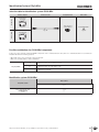
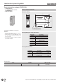
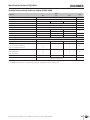
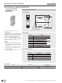
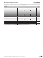
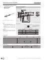
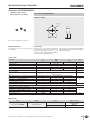
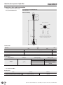
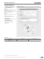
Identification System CIS3A-Mini Inductive Identification System CISA-Mini One of the smallest plug-in read heads Interface adapter for fitting on the DIN rail in the control cabinet Miniature data carrier, diameter 10 x 4 mm Read distance maximum 6.5 mm (static, on installation in non-metallic material) Data carrier memory capacity 116 bytes E2PROM read/write Easy connection of the read-only adapter to I/O on any control system via 4-bit parallel interface (24 V), max. 4 bytes of the data carrier usable via parallel interface Read/write interface adapter with serial interface RS22 or RS422, complete memory of 116 bytes usable via serial interface The innovative identification system CIS3A-Mini is used if there is very little space to fit a data carrier to the product to be identified, or if there is very little space available for the read head. Incredibly small dimensions characterize the CIS3A-Mini where the read/ write head and data carrier are concerned. Typical applications are for example tool identification or modern, very complex compact assembly installations with small product carriers. The round data carriers are bonded in a countersunk hole. Due to the high quality design of the data carrier with ferrite core, a relatively large read distance is even achieved on installation in metal, despite the small antenna. The antenna and the interface electronics are located in separate housings and are connected via a special connection cable. The data carrier and the head contain round-shaped antennae. The orientation of the data carrier in relation to the head is unimportant. This fact means that the data carrier can approach the head from any direction. The data carrier can only be read or written if it is static in front of the read head. The following components are necessary for the operation of a read station: Read head Read-only interface adapter Connection cable for connection of read head to interface adapter The following components are necessary for the operation of a read/write station: Read head (here with read/write functionality) Read/write interface adapter Connection cable for connection of read head to interface adapter Subject to technical modifications; no responsibility is accepted for the accuracy of this information. 1 Identification System CIS3A-Mini 32 Subject to technical modifications; no responsibility is accepted for the accuracy of this information. Identification System CIS3A-Mini Selection table for identification system CIS3A-Mini Read only Interface adapter Connection cable Read/write head Data carrier Read/write head CIT3ASX1N12ST CIS3AP10D05KH01K... Parallel interface CIA3PLG08 Page 34 Read / write 0815EEEE Page 40 Serial interface CIA3SX1R1G08 Page 38 Page 39 Page 36 Possible combinations for CIS3A-Mini components To give you a quick overview of which CIS3A-Mini components can be combined with each other, there is a combinations table for each read head. The table will answer the following questions: Which data carrier can be read by the selected read head? What is the operating distance of this combination? L 6.5 Key to symbols S6 Combination possible, max. read distance 6.5 mm Combination possible, max. write distance 6 mm Combination not permissible Identification system CIS3A-Mini Data carriers Read/write station CIS3AP10D05KH01K... All items Interface adapter CIA3... All items with read/write head CIT3ASX1N12ST L 6.5 S6 077 940 Subject to technical modifications; no responsibility is accepted for the accuracy of this information. 33 Identification System CIS3A-Mini Read-only interface adapter CIA3PL1G08 Parallel interface In combination with read head CIT3ASX1N12ST DIN rail mounting Interface adapter CIA3PL1G08 Dimension drawing 114 22,50 H1 H2 LED+ LEDUB OV SH RST 99 CIS3 STATE ACTIVE Str.1 Str.2 OV Skip D C B A Suitable for 35 mm DIN rail acc. to DIN EN 60715 TH35 For possible combinations see page 33 Attention: The connection cable to the control system is allowed to be max. 15 m long. On the usage of a screened cable the connection cable to the read head is allowed to be max. 15 m long. It is only ever possible to connect 1 read head per interface adapter. Pin assignment power supply and interface Designation Description 0V/GND Ground, DC 0 V 24 V/UB Power supply, DC 24 V A Output data wire A B Output data wire B C Output data wire C D Output data wire D SKIP Input data clock STROBE 1 Output data carrier active RST Input RESET Pin assignment read head Designation Description H1 Read head antenna Wire color BN H2 Read head antenna WH LED + Read head LED YE LED - Read head LED GN SH Read head screen BK Ordering table 34 Series Interface Order no. / item Read-only adapter for CIS3A-Mini Parallel 091 875 CIA3PL1G08 Subject to technical modifications; no responsibility is accepted for the accuracy of this information. Identification System CIS3A-Mini Technical data read-only interface adapter CIA3PL1G08 Parameter Value min. typ. Housing material 0.12 0 - Degree of protection according to EN 60529 kg +55 35 mm DIN rail acc. to DIN EN 60715 TH35 Connection type Plug-in screw terminals Cable length to control system - - 15 Cable length to read head - - 15 20 24 28 - 65 100 Current consumption IB (without load current) °C IP20 Mounting Operating voltage UB (regulated, residual ripple < 5 %) Unit Plastic Weight Ambient temperature at UB = DC 24 V max. m V DC 1) mA Interface/data transfer Interface to I/O on a control system Load current per output IA (push-pull) 4-bit parallel, binary coded via HIGH/LOW level - - 30 mA A, B, C, D, STROBE = 1 (HIGH level) UB - 3 - UB V DC A, B, C, D, STROBE = 0 (LOW level) 0 - 2 SKIP = 1 (HIGH level) 15 - UB SKIP = 0 (LOW level) 0 - 2 Input resistance Ri (RESET input and SKIP input) - 4.5 - Output voltage UA Input voltage UE LED indication V DC kOhm Green: Ready (in operation) Yellow: Data carrier active 2) 1) Continuous current in operation. 2) The LED illuminates yellow if there is a functional data carrier in the operating distance in front of the read head. Subject to technical modifications; no responsibility is accepted for the accuracy of this information. 35 Identification System CIS3A-Mini Read/write interface adapter CIA3SX1R1G08 Serial interface RS232/RS422 In combination with read head CIT3ASX1N12ST DIN rail mounting Interface adapter CIA3SX1R1G08 Dimension drawing 114 22,50 H1 H2 LED+ LEDUB OV SH1 OUT 99 CIS3 STATE ACTIVE RXD TDX OV SH2 A B A1 B1 Suitable for 35 mm DIN rail acc. to DIN EN 60715 TH35 For possible combinations see page 33 Serial interface The individual commands for reading and writing the data carrier are in accordance with the common 3964R protocol and are described in the EUCHNER CIS3 system manual (order no. 084 727). For data carrier programming away from the system, a convenient WINDOWS®-compatible PC software application is available (Software Transponder Coding, see page 41). Attention: On the usage of a screened cable the connection cable for the serial interface is allowed to be max. 5 m long for RS232 and max. 1000 m long for RS422. On the usage of a screened cable the connection cable to the read/write head is allowed to be max. 15 m long. It is only ever possible to connect 1 read head per interface adapter. Pin assignment Designation 0V/GND Description Ground, DC 0 V 24 V/UB Power supply, DC 24 V TxD Serial interface transmit RxD Serial interface receive A/TxD+ Serial interface transmit + B/TxD- Serial interface transmit - A1/RxD+ Serial interface receive + RS232 RS422 B1/RxD- Serial interface receive - OUT Output data carrier active, 24 V SH2 Screen data wire Pin assignment read head Designation Description H1 Read head antenna Wire color BN H2 Read head antenna WH LED + Read head LED YE LED - Read head LED GN SH1 Read head screen BK Ordering table Series Interface Order no. / item Read/write interface adapter for CIS3A-Mini Serial RS232 / RS422 077 910 CIA3SX1R1G08 36 Subject to technical modifications; no responsibility is accepted for the accuracy of this information. Identification System CIS3A-Mini Technical data read/write interface adapter CIA3SX1R1G08 Parameter Value min. typ. Housing material 0.12 0 - Degree of protection according to EN 60529 °C 35 mm DIN rail acc. to DIN EN 60715 TH35 Connection type Current consumption IB (without load current) kg +55 IP20 Mounting Operating voltage UB (regulated, residual ripple < 5 %) Unit Plastic Weight Ambient temperature at UB = DC 24 V max. Plug-in screw terminals 20 24 28 V DC - 65 100 mA 28.8 kbaud Interface/data transfer Interface to the PC or to the control system Serial RS232 / RS422 (can be changed using rotary switch) Transfer protocol Data transfer rate (selectable with DIP switch) 3964R 9.6 Data format - 1 start bit, 8 data bits, 1 parity bit (even parity), 1 stop bit Cable length RS232 interface - - 5 Cable length RS422 interface - - 1000 LED indication m Green: Ready (in operation) Yellow: Data carrier active 1) 1) The LED illuminates yellow if there is a functional data carrier in the operating distance in front of the read/write head. Subject to technical modifications; no responsibility is accepted for the accuracy of this information. 37 Identification System CIS3A-Mini Read/write head CIT3ASX1N12ST Use with interface adapter CIA3... Cylindrical design M12 M8 plug connector Axial connection Read/write head CIT3ASX1N12ST M8 plug, 4-pin, axial connection Dimension drawing s Read distance 38 inserted 50 to insert SW 17 19,7 M12x1 m 32 1) 4 EUCHNER For possible combinations see page 33 1) Clear zone M8x1 Center offset Active face 1) 5 8 30 39 For connection cable see page 40 Note The read head CIT3ASX1N12ST has Read-only functionality in combination with the read-only interface adapter with parallel interface Read/write functionality in combination with the read/write interface adapter with serial interface Pin assignment Attention: On the usage of a screened cable the connection cable to the interface adapter is allowed to be max. 15 m long. Pin Designation Description Wire color 1 H1 Antenna H1 BN 2 LED + LED connection + YE 3 H2 Antenna H2 WH 4 LED - LED connection - GN Screen BK 2 (LED+) 4 (LED-) 1 (H1) 3 (H2) The screen on the connection cable is connected to the read/write head's housing via the knurled nut on the M8 plug connector. View on the connection side of the read head - Technical data Value Parameter min. Housing material typ. max. Unit Brass (CuZn) nickel-plated Weight 0.02 Degree of protection according to EN 60529 IP65 Ambient temperature -25 Type of installation - kg +50 °C Non-flush Ordering table Series Read/write head for CIS3A-Mini 38 Use Connection Order no. / item With interface adapter CIA3 M8 plug connector axial connection 077 940 CIT3ASX1N12ST Subject to technical modifications; no responsibility is accepted for the accuracy of this information. Identification System CIS3A-Mini Data carrier CIS3AP10D05KH01K... Cylindrical design ∅ 10 mm Unprogrammed or programmed Data carrier CIS3AP10D05KH01K... Dimension drawing Active face 0815EEEE 0 9,98 -0,05 4 +0,2 0 For possible combinations see page 33 Mounting instructions For fastening use e.g. two-component epoxy resin adhesive. Programming The data carrier can be written (programmed) for read-only operation with a maximum of 8 hexadecimal digits (value from 0hex to Fhex) on customer request. Standard filler digit after the customer-specific defined digits is Ehex. The housing is permanently laser marked with the digits programmed (not including filler digits) in hexadecimal notation. Technical data Value Parameter min. Memory capacity (read/write) - Housing material typ. max. 116 - Unit bytes Plastic PPS Weight 0.001 Degree of protection according to EN 60529 kg IP67 Ambient temperature -25 Type of installation - +70 °C Bonded, flush (also in metal) Memory organization Write Read Only possible in 4-byte blocks Possible byte by byte Operating parameters on reading using read/write head CIT3ASX1N12ST and interface adapter CIA3PL1G08 or CIA3SX1R1G08 Read distance sL for non-metallic environment 0 3 6.5 Read distance sL on flush installation in iron 0 3 6 Read distance sL on flush installation in aluminum 0 3 5 Center offset mL (for sL = 3 mm) - - ± 2.5 Number of read cycles mm Not limited Operating parameters on writing using read/write head CIT3ASX1N12ST and interface adapter CIA3SX1R1G08 Write distance sS for non-metallic environment 0 3 6 Write distance sS on flush installation in iron 0 3 5.5 Write distance sS on flush installation in aluminum 0 3 4.5 - - ±2 100,000 - - Center offset mS (for sS = 3 mm) Number of write cycles mm cycles Ordering table Series Design Data carrier for CIS3A-Mini Cylindrical ∅ 10 mm Version Unprogrammed Programmed Subject to technical modifications; no responsibility is accepted for the accuracy of this information. Order no. / item 077 785 CIS3AP10D05KH01K 092 320 CIS3AP10D05KH01K-P 39 Identification System CIS3A-Mini Connection cables and documentation For read/write head CIT3ASX1N12ST M8 socket, 4-pin Dimension drawing 22,5 ∅10 31 Screened connection cable for read/ write head CIT3ASX1N12ST View of connection side 2 (LED+) 4 (LED-) 3 (H2) "l" 1 = BN 2 = YE 3 = WH 4 = GN BK ∅4,6 1 (H1) H1 LED + H2 LED Screen 30 Crimped ferrules The screen on the connection cable is connected to the read head's housing via the knurled nut on the M8 plug connector. Technical data Value Parameter min. typ. Plug connectors 4-pin M8 female plug, straight Connection type Screw terminal, knurled nut electrically connected to cable screen Conductor cross-section Unit max. 4 x 0.25 screened Material, outer sheath mm² PVC Ordering table Plug connectors Cable type Cable length l [m] 2 Straight 5 V Cable PVC 10 15 Order no / item 084 641 C-M08F04-04X025PV02,0-ES-084641 084 642 C-M08F04-04X025PV05,0-ES-084642 084 643 C-M08F04-04X025PV10,0-ES-084643 084 644 C-M08F04-04X025PV15,0-ES-084644 User manual CIS3A-Mini Ordering table Series Manual Inductive Identification System CIS3A-Mini Comment PDF file as download Order no. 1) 084 727 1) Downloads available at www.euchner.de in Download/Manuals/Automation/Identification systems. 40 Subject to technical modifications; no responsibility is accepted for the accuracy of this information. Identification System CIS Transponder Coding (TC) Software for writing the data carriers In conjunction with read/write stations with serial RS232 interface Transponder Coding (TC) Description The Transponder Coding (TC) software is an ASCII/hex editor that can be used to read and write the data carrier on the PC. The software is used in conjunction with a read/ write station with serial interface. Overview Display of the data in ASCII and in hex notation Byte-wise editing of the data Storage of the data as ASCII or hex file on PC System requirements Operating system: Microsoft Windows® 98/ ME/NT/2000/XP/Vista/7 Processor: from Pentium 2 Available memory: min. 64 MB Hard disk space for the installation: approx. 20 MB Interface: serial Ordering table Designation Comment Order no. / item Software Transponder Coding On CD 067 190 Windows® is a registered trademark of Microsoft Corporation Subject to technical modifications; no responsibility is accepted for the accuracy of this information. 41