1
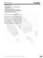
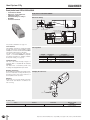
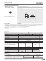
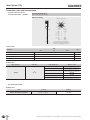
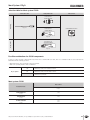
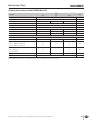
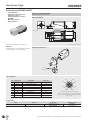
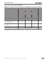
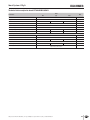
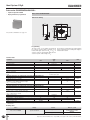
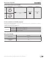
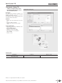
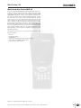
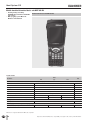
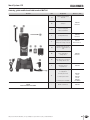
Ident System CIS More than safety. Automation More than safety. Around the world – the Swabian specialists in motion sequence control for mechanical and systems engineering. Emil Euchner, the company’s founder and inventor of the multiple limit switch, circa 1928. EUCHNER’s history began in 1940 with the establishment of an engineering office by Emil Euchner. Since that time, EUCHNER has been involved in the design and development of switchgear for controlling a wide variety of motion sequences in mechanical and systems engineering. In 1953, Emil Euchner founded EUCHNER + Co., a milestone in the company’s history. In 1952, he developed the first multiple limit switch – to this day a symbol of the enterprising spirit of this familyowned company. Automation – Safety – ManMachine Today, our products range from electromechanical and electronic components to complex system solutions. With this wide range of products we can provide the necessary technologies to offer the right solution for special requirements – regardless of whether these relate to reliable and precise positioning or to components and systems for safety engineering in the automation sector. EUCHNER products are sold through a world-wide sales network of competent partners. With our closeness to the customer and the guarantee of reliable solutions throughout the globe, we enjoy the confidence of customers all over the world. Quality, reliability, precision Quality, reliability and precision are the hallmarks of our corporate philosophy. They represent concepts and values to which we feel totally committed. At EUCHNER, quality means that all our employees take personal responsibility for the company as a whole and, in particular, for their own field of work. This individual commitment to perfection results in products which are ideally tailored to the customers’ needs and the requirements of the market. After all: our customers and their needs are the focus of all our efforts. Through efficient and effective use of resources, the promotion of personal initiative and courage in finding unusual solutions to the benefit of our customers, we ensure a high level of customer satisfaction. We familiarize ourselves with their needs, requirements and products and we learn from the experiences of our customers’ own customers. EUCHNER – More than safety. Quality – made by EUCHNER 2 Contents Ident Systems CIS General Information 4-5 System Overview 6-8 Ident System CIS3 Read-only heads CIS3 with parallel interface Read/write head CIS3 with serial interface Data carrier CIS3 Connection cables and documentation CIS3 9 12 14 16 18 Ident System CIS3A Read-only heads CIS3A with parallel interface Read/write head CIS3A with serial interface Data carrier CIS3A Connection cables and documentation CIS3A 19 22 26 28 29 Ident System CIS3A-Mini31 Read-only interface adapter CIS3A-Mini with parallel interface 34 Read/write interface adapter CIS3A-Mini with serial interface 36 Read/write head CIS3A-Mini 38 Data carrier CIS3A-Mini 39 Connection cables and documentation CIS3A-Mini 40 Transponder Coding (TC) 41 Mobile Hand-Held Terminal MHT-G2 Mobile hand-held terminal Basic unit MHT-G2-BU Ordering guide mobile hand-held terminal 43 44 45 Item Index 46 Product Guide 49 076660-01-04/10 General Inductive Ident Systems CIS Applications Integration for read-only operation Inductive ident systems are used for the non-contact identification of products such as tools, product carriers or containers in the entire manufacturing and logistics sector. The data carriers for the ident systems CIS are mostly programmed with a unique sequential number. The product is identified at a read station using this number and the related production data are then assigned to the product. The ident system CIS is mostly used in installation as a read-only system with the 4-bit parallel interface. The advantage of the parallel interface is simple integration into the control system and the transparent representation of the data. Quick and therefore low-cost integration into any type of PLC is possible. The data carriers are read using a completely wear-free inductive coupling. The read heads and data carriers are of robust design, have a high degree of protection and are designed for harsh industrial usage. The ident system will also work without problems when subject to dirt and moisture. System overview and function The ident system CIS essentially comprises the following components: Data carrier Read-only station or read/write station with data interface The ident systems CIS3, CIS3A and CIS3A-Mini are very similar with regard to the interfaces to the higher level control system. As a result the integration into the control system is similar. There are differences, on the one hand, in the design of the antenna and, on the other hand, in the design of the components. The special features and advantages of the individual systems as well as the related system components are divided into separate sections for the systems CIS3, CIS3A and CIS3A-Mini. The components for the different ident systems CIS3, CIS3A and CIS3A-Mini must not be mixed between the systems, i. e. a CIS3 read head is not suitable for reading a CIS3A data carrier. The read stations and read/write stations for the CIS3 and CIS3A are fitted compactly in one housing. In the case of the CIS3A-Mini the stations are split in two for space reasons, that is interface adapter and antenna are connected via an antenna cable. Power is supplied to the transponder and the data are transferred between the read/write station and the data carrier without using any contacts. The CIS ident system operates on the principle of inductive coupling in the near field, based on a carrier frequency of 125 kHz. This standard frequency at the low end of the frequency band used for RFID applications makes it possible, if necessary, to even install the data carrier flush in metal. However, it will certainly be of advantage if a non-metallic material is used in the immediate area around the data carrier. A memory chip and an antenna are fitted in the data carrier, in various shapes (transponder). The E2PROM to which data can be written (programmable) retains the data in non-volatile form. For all standard data carriers used for CIS the following applies: Transponder without battery Robust encapsulated data carrier housing with degree of protection IP67 The read-only stations communicate with the higher level control system via a 4-bit parallel interface and the read/write stations via a serial interface. 4 The 4 data wires, which are connected directly to the PLC via inputs and outputs (I/O), represent at a point in time a related hex digit using high/low levels (24 V/0 V). After the read station is switched on, the level on all 4 wires is initially high. If a data carrier now enters the operating distance of the read station, first the data are automatically transferred from the data carrier to the memory in the read station and stored there temporarily. In the second step, the data are actively retrieved from the memory in the read station by the control system. For the second step it is no longer necessary for the data carrier to be in the read head's operating distance. The read station saves the data from a data carrier read until the next data carrier is fed to the read station or the read station is switched off and on again. In the case of the CIS3A-Mini it is also possible to delete the temporary memory in the read station via a reset pulse. If there is a data carrier in front of the read head, the data are transferred again automatically. In the first step, it is signaled to the control system via the high level on the STROBE output on the read station that there is a data carrier in the operating distance and new data are available in the memory on the read station. The STROBE output is set to the high level when the first 4 hex digits on the CIS3/CIS3A and the first 8 hex digits on the CIS3A Mini are available in the memory on the read station. If in the case of the CIS3/CIS3A more than 4 hex digits are required in the application, it is necessary to wait long enough until all the digits have been transferred to the memory in the read station (see pulse diagram in the manual for the read station). If, for some reason (e. g. excessively high relative speed), it was not possible to read all the digits, on the output of the data Fhex is output as an error message from the point at which the data were no longer read from the data carrier. In the second step, the data can be retrieved from the temporary memory in the read station by the control system. A value between 0 and 15 is represented at a point in time via a combination of high/low levels on the data outputs on the read station using binary coding (high level on A=1, B=2, C=4, D=8). The first digit from the data carrier is indicated immediately on the 4-bit data wire. Using pulses from the control system on the SKIP input on the read station, a maximum of 32 hex digits (16 bytes) can be read with the CIS3/CIS3A and 8 hex digits (4 bytes) with the CIS3A Mini. Reference is to be made to the pulse diagram in the manual for the read station for information on the timing of the pulses. If the SKIP input on the read station is maintained static at a high level, no data are transferred from the data carrier into the memory in the read station. By maintaining the SKIP signal at the high level prior to the entry of the data carrier in the operating distance, on the change in the SKIP signal to the low level the data can be read statically at this defined point in time. As long as the SKIP input is maintained at the high level, the STROBE output remains at the low level, even if there is a data carrier in the operating distance of the read head. The signaling that there is a read head in front of the read head must therefore be provided separately if you want to use this reading method. On the application of this method of control, a CIS3 data carrier can, for instance, approach the read head in the opposite direction to the arrow. Subject to technical modifications; no responsibility is accepted for the accuracy of this information. General In typical applications 2, 3 or 4 digits of these 8 (CIS3AMini) or 32 (CIS3/ CIS3A) possible digits are combined to form a number and used in the application. Hereby, e. g. 150 product carriers (3 digits) with 001, 002, 003 to 150 are sequentially numbered in decimal notation. The definition of the sequence of numbers with leading zeros produces a logical series. The data carrier then has a data record address that is used to store the actual production information in the control system. In this example with 3 available digits, 999 different product carriers could be addressed in decimal notation. In the case of a 3-digit number, the data are provided on the 4-bit data wire in the following sequence: the first digit is displayed automatically, the second digit is displayed after the first SKIP pulse from the control system and the third digit is displayed after the second SKIP pulse. the data carriers (programming). For this purpose the programming software Transponder Coding (TC) is installed on the PC. TC is an ASCII/hex editor with which it is easy to write to and read from the data carrier on the PC. There exist the following possible ways of programming the data carriers with digits: In the case of read/write stations with serial interface, the data communication is according to the 3964R transfer protocol. The individual commands, e. g. for reading the data or writing the data, are described in the device-specific manuals. For unusual CIS applications in which data carriers must also be re-programmed during production, the application is programmed in the control system with the aid of these commands based on the 3964R transfer protocol. It is also possible to write to and read from data carriers with the aid of the portable mobile hand-held terminal MHT-G2. For this purpose a read/write head to suit the related ident system is fitted. The data carriers can be read and written (programmed) using the software Transponder Coding CE (TCCE). TCCE is an ASCII/hex editor with which it is easy to write to and read from the data carrier on the MHT. Integration for read/write operation Order programmed data carriers Program in-house using read/write station with serial interface Program in-house using mobile hand-held terminal The data carrier can be written (programmed) for read-only operation on customer request and also visibly labelled using a laser. In this case a data carrier programming and labelling information form is to be completed with the order. This form is available for download from www.euchner.de. Interfacing of a read/write station with serial interface to the user's PC-based application is supported by the optionally available ActiveX® modules (can be used if Microsoft Windows®-based user programs support ActiveX®). CIS can thus be used in conjunction with PC-based control software or visualization software. The ActiveX® module is used here as a protocol driver for the 3964R transfer protocol. You can obtain further information on the usage of an ActiveX® module on request. You will have significantly more flexibility if you have your own facility for data carrier programming. The read/write station for the related ident system with a serial interface can be used on a PC for easy writing to Block diagram ident system CIS3/CIS3A Read/write head Serial interface Input Parallel interface Control system PLC PC Input Input Input Input Output Static reading/ writing, data carriers with 32 digits can be used max. 5 m screened STROBE A Value 1 B Value 2 C Value 4 D Value 8 Read-only head Static or dynamic reading, data carriers with 32 digits can be used max. 50 m screened SKIP Block diagram ident system CIS3A-Mini Read/write station Serial interface Input Parallel interface Control system PLC PC Input Input Input Input Output Output max. 5 m for RS232 / max. 1000 m for RS422 max. 15 m screened screened 0815EEEE Static reading/ writing, data carriers with 116 bytes can be used STROBE A Value 1 B Value 2 C Value 4 Read-only station max. 15 m max. 15 m 0815EEEE D Value 8 SKIP screened Static reading, data carriers with 8 digits can be used RESET Microsoft Windows® and ActiveX® are registered trademarks of Microsoft Corporation Subject to technical modifications; no responsibility is accepted for the accuracy of this information. System Overview Features and possible combinations for CIS components Combination possible Key to symbols Combination not permissible Read distance max. 18 mm CIS3 Dynamic reading up to 410 mm/s Coding of recirculating product carriers or larger tools with standard read distances All items CIS3AP10D05KH01K... All items CIS3AP50X50SH16YSNO... Interface adapter, read/write head All items Applications CIS3P16D08KH16YSNO... Features All items Ident system CIS3P35X16SH16Y... Data carriers Read-only head CIT3PL1N30-STA 071 552 Read-only head CIT3PL1N30-STR 071 950 Read/write head CIT3SX1R1G05KX 096 560 Read distance max. 28 mm CIS3A Dynamic reading up to 230 mm/s Coding of slowly recirculating product carriers or very large tools at increased read distances Read-only head CIT3APL1N30-STA 071 900 Read-only head CIT3APL1G05ST 077 805 Read/write head CIT3ASX1R1G05KX 1) 077 890 CIS3A-Mini Miniature dimensions Read distance max. 6.5 mm Coding of tools or small product carriers Interface adapter CIA3... All items with read/write head CIT3ASX1N12ST 077 940 1) To set up a programming station for CIS3A-Mini data carriers, a CIS3A read/write head can be used. Subject to technical modifications; no responsibility is accepted for the accuracy of this information. System Overview Ident system CIS3 Read / write Read only Interface adapters Parallel interface integrated in the read head Serial interface integrated in the read/write head Read/write heads CIT3PL1N30-ST... Read-only head Cylindrical design M30 M12 plug connector Axial or radial connection (see page 12) CIT3SX1R1G05KX Read/write head Housing according to EN 50041 Connection terminals (see page 14) Data carriers CIS3P35X16SH16YHNO... Cube-shaped Approach direction horizontal (see page 16) CIS3P35X16SH16YVNO... Cube-shaped Approach direction vertical (see page 16) CIS3P16D08KH16YSNO... Cylindrical ∅ 16 mm (see page 17) Ident system CIS3A Read / write Read only Interface adapters Parallel interface integrated in the read head Serial interface integrated in the read/write head Read/write heads Data carriers CIT3APL1N30-STA Read-only head Cylindrical design M30 M12 plug connector Axial connection (see page 22) CIT3APL1G05ST Read-only head Housing according to EN 50041 M12 plug connector Axial connection (see page 24) CIS3AP50X50SH16YSNO... Square (see page 28) CIT3ASX1R1G05KX Read/write head Housing according to EN 50041 Connection terminals (see page 26) Ident system CIS3A-Mini Interface adapters Read/write heads Data carriers Read / write Read only Parallel interface CIA3PL1G08 Plug-in screw terminals (see page 34) Serial interface CIA3SX1R1G08 Plug-in screw terminals (see page 36) CIT3ASX1N12ST Read/write head Cylindrical design M12 M8 plug connector Axial connection (see page 38) Subject to technical modifications; no responsibility is accepted for the accuracy of this information. CIS3AP10D05KH01K... Cylindrical ∅ 10 mm (see page 39) System Overview Mobile hand-held terminal MHT-G2 Basic unit Accessories Rechargeable battery MHT-G2-BA (see page 45) SD memory card MHT-G2-SD-TCCE With software Transponder Coding CE (TCCE) (see page 45) MHT-G2-BU For reading and programming the data carriers With touch-pen and cover for rechargeable battery compartment (see page 44) Docking station MHT-G2-DS With power supply unit and USB connecting cable (see page 45) Extension cable For read/write head (see page 45) Read/write head CIT3-H2 For ident system CIS3 (see page 45) Read/write head CIT3A-H2 For ident system CIS3A (see page 45) Read/write head CIT3A-MINI-H2 For ident system CIS3A-Mini (see page 45) Subject to technical modifications; no responsibility is accepted for the accuracy of this information. Ident System CIS3 Ident System CIS Low-cost read/write system with predominantly used, separate read-only heads Extremely compact head design, no separate interface adapter required Read distance maximum 18 mm Dynamic reading with a relative speed up to 410 mm/s Data carrier memory capacity 16 bytes E2PROM read/write Easy connection of the read-only heads to I/O on any control system via 4-bit parallel interface (24 V) Read/write heads with serial interface RS22 The ident system CIS3 is the predominantly used standard system in the CIS system family. The CIS3 features compact data carriers. Typical applications are, e. g., the coding of recirculating product carriers or larger tools. The data carriers are screwed on the product to be identified or the round design is bonded in a countersunk hole. The antenna and the interface electronics are fully integrated in the read heads and the read/write head. The data carrier and the head contain stick-shaped antennae. This configuration requires mounting with the same orientation of the head and data carrier. This orientation can be seen from a printed arrow marking. This fact means that the data carrier must approach the head in the direction of the arrow. The data carriers can be read when static or even moving at relative speed in front of the read head, i. e. on moving past. As a result the system is suitable, for instance, for moving product carriers. The data carrier must always be static for writing. Subject to technical modifications; no responsibility is accepted for the accuracy of this information. 9 Ident System CIS3 10 Subject to technical modifications; no responsibility is accepted for the accuracy of this information. Ident System CIS3 Selection table for ident system CIS3 Connection cable Read/write heads Data carriers Read-only head CIT3PL1N30-STA Horizontal CIS3P35X16SH16YHNO... Page 16 Read only Page 12 Page 18 Read-only head CIT3PL1N30-STR Vertical CIS3P35X16SH16YVNO... Page 16 Page 12 Read / write Read/write head CIT3SX1R1G05KX CIS3P16D08KH16YSNO... 4322ABCD Page 17 Page 14 Possible combinations for CIS3 components To give you a quick overview of which CIS3 components can be combined with each other, there is a combinations table for each read head. The table will answer the following questions: Which data carrier can be read by the selected read head? What is the operating distance of this combination? Key to symbols L 18 Combination possible, max. read distance 18 mm S9 Combination possible, max. write distance 9 mm Combination not permissible Ident system CIS3 Data carriers Read/write heads Read-only head CIT3PL1N30-STA CIS3P35X16SH16Y... CIS3P16D08KH16YSNO... All items All items L 18 L 14 L 18 L 14 L 18 S 10 L 14 S9 071 552 Read-only head CIT3PL1N30-STR 071 950 Read/write head CIT3SX1R1G05KX 096 560 Subject to technical modifications; no responsibility is accepted for the accuracy of this information. 11 Ident System CIS3 Read-only heads CIT3PL1N30-ST... Parallel interface Cylindrical design M30 M12 plug connector Axial or radial connection Read-only head CIT3PL1N30-STA M12 plug, 8-pin, axial connection Dimension drawing 90 SW 36 LED 42 M12x1 m 5 Data carrier M30x1,5 s Center offset 90 1) Read distance 16 1) Clear zone 1) Active face Crossing direction 20 60 80 For connection cable see page 18 For possible combinations see page 11 Read-only head CIT3PL1N30-STR M12 plug, 8-pin, radial connection Dimension drawing 35 5 s M12x1 LED Data carrier m Center offset 90 1) Read distance 1) Clear zone 42 Attention: On the usage of a screened cable the connection cable is allowed to be max. 50 m long. M 30x1,5 Mounting instructions On mounting the read head and data carrier, it is to be ensured the crossing direction as per the direction of the arrow on the active face of the read head is observed. 16 SW36 1) 150° Adjustment range Active face Crossing direction 20 58 80 For connection cable see page 18 Pin assignment 5 Pin Designation Description Wire color 1 0V/GND Ground, DC 0 V WH 2 24 V/UB Power supply, DC 24 V BN 3 A Output data wire A GN 4 B Output data wire B YE 5 C Output data wire C GY 6 D Output data wire D PK 7 SKIP Input data clock BU 8 STROBE - Output data carrier active RD Screen Open 8 6 4 7 3 1 2 View on the connection side of the read head The screen on the connection cable is connected to the read head's housing via the knurled nut on the M12 plug connector. Ordering table Series Read-only head for CIS3 12 Interface Parallel Connection Order no. / item M12 plug connector axial connection 071 552 CIT3PL1N30-STA M12 plug connector radial connection 071 950 CIT3PL1N30-STR Subject to technical modifications; no responsibility is accepted for the accuracy of this information. Ident System CIS3 Technical data read-only heads CIT3PL1N30-ST... Parameter Value min. Housing material typ. 0.2 -25 Operating voltage UB (regulated, residual ripple < 5 %) Current consumption IB (without load current) +50 °C IP67 Type of installation Cable length kg - Degree of protection according to EN 60529 Connection type Unit Brass (CuZn) nickel-plated Weight Ambient temperature at UB = DC 24 V max. Non-flush M12 plug connector, 8-pin, axial or radial connection, screw terminal - - 50 m 20 24 28 V DC - 65 100 1) mA Interface/data transfer Interface to I/O on a control system Load current per output IA (push-pull) 4-bit parallel, binary coded via HIGH/LOW level - - 30 mA A, B, C, D, STROBE = 1 (HIGH level) UB - 3 - UB V DC A, B, C, D, STROBE = 0 (LOW level) 0 - 2 SKIP = 1 (HIGH level) 15 - UB SKIP = 0 (LOW level) 0 - 2 Input resistance Ri (SKIP input) - 4.5 Output voltage UA Input voltage UE LED indication Yellow: Data carrier active - V DC kOhm 2) 1) Continuous current in operation. 2) The LED illuminates yellow if there is a functional data carrier in the operating distance in front of the read head. Subject to technical modifications; no responsibility is accepted for the accuracy of this information. 13 Ident System CIS3 Read/write head CIT3SX1R1G05KX Read/write head CIT3SX1R1G05KX Dimension drawing 16,5 12,5 40 40,5 Serial interface RS232 Active face can be adjusted to 5 different positions Standard housing according to EN 50041 Connection terminals M20x1,5 s Datenträger Screen bonding clamp 60 ±0,1 <30> 5,3 40 46,5 m Read distance Center offset LED status indication 7,3 Data carrier 40 Crossing direction 30 ±0,1 Active face 119 For possible combinations see page 11 Serial interface The individual commands for reading and writing the data carrier are in accordance with the common 3964R protocol and are described in the EUCHNER CIS3 system manual (order no. 071 652). For data carrier programming away from the system, a convenient WINDOWS®-compatible PC software application is available (Software Transponder Coding, see page 41). Pin assignment Standard housing The size of the robust housing in degree of protection IP65 is compliant with the standard EN 50041. The division into 3 assemblies permits easy mounting and straightforward replacement. Mounting instructions On mounting the read/write head and data carrier, it is to be ensured the crossing direction as per the direction of the arrow on the active face of the read/write head is observed. Terminal Designation Description 1 24 V/UB Power supply, DC 24 V 2 RxD Serial interface receive 3 0V/GND Ground, DC 0 V 4 TxD Serial interface transmit Changing the active face Attention: On the usage of a screened cable the connection cable for the serial interface is allowed to be max. 5 m long. B A 1 Undo screws Ordering table 14 Series Interface Connection Order no. / item Read/write head for CIS3 Serial RS232 Connection terminals 096 560 CIT3SX1R1G05KX Subject to technical modifications; no responsibility is accepted for the accuracy of this information. Ident System CIS3 Technical data read/write head CIT3SX1R1G05KX Parameter Value min. typ. Housing material 0.29 0 - Degree of protection according to EN 60529 +55 °C Non-flush Connection type Current consumption IB (without load current) kg IP65 Type of installation Operating voltage UB (regulated, residual ripple < 5 %) Unit Plastic Weight Ambient temperature at UB = DC 24 V max. Screw terminals 20 24 28 V DC - 80 120 mA - kbaud 5 m Interface/data transfer Interface to the PC or to the control system Serial RS232 Transfer protocol Data transfer rate 3964R - Data format Cable length RS232 interface LED indication 9.6 1 start bit, 8 data bits, 1 parity bit (even parity), 1 stop bit - Green: Ready (in operation) Yellow: Data carrier active 1) 1) The LED illuminates yellow if there is a functional data carrier in the operating distance in front of the read/write head. Subject to technical modifications; no responsibility is accepted for the accuracy of this information. 15 Ident System CIS3 Data carrier CIS3P35X16SH16Y... Cube-shaped design 35 x 16 mm Data carrier horizontal or vertical Unprogrammed or programmed Data carrier CIS3P35X16SH16Y... Dimension drawing 35 4,6 O8 8 16 Data carrier horizontal O 4,5 25 Crossing direction Active face 8 Crossing direction Mounting instructions On mounting the read head and data carrier, it is to be ensured the crossing direction as per the direction of the arrow on the active face of the read head or read/write head is observed. O 4,5 25 35 Data carrier vertical O8 4,6 16 For possible combinations see page 11 Active face Programming The data carrier can be written (programmed) for read-only operation with a maximum of 32 hexadecimal digits (value from 0hex to Fhex) on customer request. Standard filler digit after the customer-specific defined digits is Ehex. The housing is permanently laser marked with the digits programmed (not including filler digits) in hexadecimal notation. Technical data Value Parameter min. Memory capacity (read/write) - Housing material typ. max. 16 - Unit bytes Plastic PPS Weight 0.005 Degree of protection according to EN 60529 kg IP67 Ambient temperature -40 Type of installation - +85 °C Screw fixing, not flush (also on metal) Memory organization Write Read Only possible in 2-byte blocks Possible byte by byte Operating parameters on reading using read-only head CIT3PL1N30-STA or CIT3PL1N30-STR Read distance sL 0 7 18 Center offset mL in x direction (for sL = 7 mm) - - ± 23 Center offset mL in y direction (for sL = 7 mm) - - ±8 Relative speed for reading 4 hexadecimal digits Reduction for each additional hexadecimal digit (at sL = 7 mm and mL = 0 mm in y direction) - - 410 25 Number of read cycles mm mm/s Not limited Operating parameters on reading and writing using read/write head CIT3SX1R1G05KX Read distance sL 0 7 Write distance sS 0 5 10 Center offset mL /mS in x direction (at sL /sS = 5 mm) - - ± 10 - - ±8 100,000 - - Center offset mL /mS in y direction (at sL /sS = 5 mm) Number of write cycles 18 mm cycles Ordering table Series Design Version Horizontal, unprogrammed Data carrier for CIS3 Cube-shaped 35 x 16 mm Horizontal, programmed Vertical, unprogrammed Vertical, programmed 16 Order no. / item 084 746 CIS3P35X16SH16YHNOU 084 747 CIS3P35X16SH16YHNOP 095 950 CIS3P35X16SH16YVNOU 095 951 CIS3P35X16SH16YVNOP Subject to technical modifications; no responsibility is accepted for the accuracy of this information. Ident System CIS3 Data carrier CIS3P16D08KH16YSNO... Cylindrical design ∅ 16 mm Unprogrammed or programmed Data carrier CIS3P16D08KH16YSNO... Dimension drawing O 16 8 For possible combinations see page 11 4322EEEE Crossing direction Notes on installation On mounting the read head and data carrier, it is to be ensured the crossing direction as per the direction of the arrow on the active face of the read head or read/write head is observed. For fastening use e.g. two-component epoxy resin adhesive. Programming The data carrier can be written (programmed) for read-only operation with a maximum of 32 hexadecimal digits (value from 0hex to Fhex) on customer request. Standard filler digit after the customer-specific defined digits is Ehex. Active face The housing is permanently laser marked with the digits programmed (not including filler digits) in hexadecimal notation. Technical data Value Parameter min. Memory capacity (read/write) - Housing material typ. max. 16 - Unit bytes Plastic PPS Weight 0.003 Degree of protection according to EN 60529 kg IP67 Ambient temperature -40 - Type of installation Bonded, flush (also in metal) 1) Memory organization Write Read Only possible in 2-byte blocks Possible byte by byte +85 °C Operating parameters on reading using read-only head CIT3PL1N30-STA or CIT3PL1N30-STR 1) Read distance sL 0 5 14 Center offset mL in x direction (for sL = 5 mm) - - ± 18 Center offset mL in y direction (for sL = 5 mm) - - ±6 Relative speed for reading 4 hexadecimal digits Reduction for each additional hexadecimal digit (at sL = 5 mm and mL = 0 mm in y direction) - - 320 25 Number of read cycles mm mm/s Not limited Operating parameters on reading and writing using read/write head CIT3SX1R1G05KX 1) Read distance sL 0 5 Write distance sS 0 5 9 Center offset mL /mS in x direction (at sL /sS = 5 mm) - - ± 10 - - ±6 100,000 - - Center offset mL /mS in y direction (at sL /sS = 5 mm) Number of write cycles 14 mm cycles 1) On flush installation in a non-metallic material, better operating parameters as for the data carriers CIS3P35X16SH16Y... are obtained Ordering table Series Design Data carrier for CIS3 Cylindrical ∅ 16 mm Version Unprogrammed Programmed Subject to technical modifications; no responsibility is accepted for the accuracy of this information. Order no. / item 088 832 CIS3P16D08KH16YSNOU 088 833 CIS3P16D08KH16YSNOP 17 Ident System CIS3 Connection cables and documentation Screened connection cable for read-only heads CIT3PL.../CIT3APL... For read-only heads CIT3 M12 socket, 8-pin, silicone-free Dimension drawing View of connection side ∅ 14 8 5 4 6 3 7 2 "l" 1 2 3 4 5 6 7 8 = = = = = = = = ∅6 WH BN GN YE GY PK BU RD Open 1 0 V/GND 24 V/UB A B C D SKIP STROBE Screen The screen on the connection cable is connected to the read head's housing via the knurled nut on the M12 plug connector. Technical data Value Parameter min. typ. Plug connector 8-pin M12 female connector, straight Connection type Screw terminal, knurled nut electrically connected to cable screen Conductor cross-section Unit max. 8 x 0.25 screened Material, outer sheath mm² PVC Ordering table Plug connectors Cable type Cable length l [m] 5 10 Straight 15 V Cable PVC 20 25 50 Order no / item 077 751 C-M12F08-08X025PV05,0-ZN-077751 077 752 C-M12F08-08X025PV10,0-ZN-077752 077 753 C-M12F08-08X025PV15,0-ZN-077753 077 871 C-M12F08-08X025PV20,0-ZN-077871 077 872 C-M12F08-08X025PV25,0-ZN-077872 077 873 C-M12F08-08X025PV50,0-ZN-077873 User manual CIS3/CIS3A Ordering table Series Manual Inductive Ident System CIS3/CIS3A Comment PDF file as download Order no. 1) 071 652 1) Downloads available at www.euchner.de in Download/Manuals/Automation/Ident systems. 18 Subject to technical modifications; no responsibility is accepted for the accuracy of this information. Ident System CIS3A Inductive Ident System CISA Low-cost read/write system with predominantly used, separate read-only heads Extremely compact head design, no separate interface adapter required Read distance maximum 28 mm Dynamic reading with a relative speed up to 20 mm/s Data carrier memory capacity 16 bytes E2PROM read/write Easy connection of the read-only heads to I/O on any control system via 4-bit parallel interface (24 V) Read/write heads with serial interface RS22 The ident system CIS3A is used if somewhat larger read distances are required. As a result a larger data carrier is necessary. The data carrier is screwed on the product to be identified. The antenna and the interface electronics are fully integrated in the read heads and the read/write head. The data carrier and the head contain round-shaped antennae. The orientation of the data carrier in relation to the head is unimportant. This fact means that the data carrier can approach the head from any direction. The data carriers can be read when static or moving at low relative speed in front of the read head, i. e. on moving past. The data carrier must always be static for writing. Subject to technical modifications; no responsibility is accepted for the accuracy of this information. 19 Ident System CIS3A 20 Subject to technical modifications; no responsibility is accepted for the accuracy of this information. Ident System CIS3A Selection table for ident system CIS3A Connection cable Read/write heads Data carriers Read-only head CIT3APL1N30-STA Read only Page 22 Page 29 Read-only head CIT3APL1G05ST CIS3AP50X50SH16YSNO... Page 24 Page 28 Read / write Read/write head CIT3ASX1R1G05KX Page 26 Possible combinations for CIS3A components To give you a quick overview of which CIS3A components can be combined with each other, there is a combinations table for each read head. The table will answer the following questions: Which data carrier can be read by the selected read head? What is the operating distance of this combination? Key to symbols L 20 Combination possible, max. read distance 20 mm S 28 Combination possible, max. write distance 28 mm Combination not permissible Ident system CIS3A Data carriers Read/write heads CIS3AP50X50SHYSNO... All items Read-only head CIT3APL1N30-STA L 20 071 900 Read-only head CIT3APL1G05ST L 28 077 805 Read/write head CIT3ASX1R1G05KX 077 890 Subject to technical modifications; no responsibility is accepted for the accuracy of this information. L 28 S 28 21 Ident System CIS3A Read-only head CIT3APL1N30-STA Read-only head CIT3APL1N30-STA M12 plug, 8-pin, axial connection Dimension drawing m 5 16 1) Clear zone SW 36 LED Data carrier M30x1,5 s Center offset 90 1) Read distance 90 42 Parallel interface Cylindrical design M30 M12 plug connector Axial connection M12x1 1) Active face 20 60 80 For connection cable see page 29 For possible combinations see page 21 Attention: On the usage of a screened cable the connection cable is allowed to be max. 50 m long. Pin assignment Pin Designation Description Wire color 1 0V/GND Ground, DC 0 V WH 2 24 V/UB Power supply, DC 24 V BN 3 A Output data wire A GN 4 B Output data wire B YE 5 C Output data wire C GY 6 D Output data wire D PK 7 SKIP Input data clock BU 8 STROBE Output data carrier active RD Screen Open - 5 8 6 4 7 3 1 2 View on the connection side of the read head The screen on the connection cable is connected to the read head's housing via the knurled nut on the M12 plug connector. Ordering table Series Read-only head for CIS3A 22 Interface Connection Order no. / item Parallel M12 plug connector axial connection 071 900 CIT3APL1N30-STA Subject to technical modifications; no responsibility is accepted for the accuracy of this information. Ident System CIS3A Technical data read-only head CIT3APL1N30-STA Parameter Value min. Housing material typ. 0.2 -25 Operating voltage UB (regulated, residual ripple < 5 %) Current consumption IB (without load current) +50 °C IP67 Type of installation Cable length kg - Degree of protection according to EN 60529 Connection type Unit Brass (CuZn) nickel-plated Weight Ambient temperature at UB = DC 24 V max. Non-flush M12 plug connector, 8-pin, axial connection, screw terminal - - 50 m 20 24 28 V DC - 65 100 1) mA Interface/data transfer Interface to I/O on a control system Load current per output IA (push-pull) 4-bit parallel, binary coded via HIGH/LOW level - - 30 mA A, B, C, D, STROBE = 1 (HIGH level) UB - 3 - UB V DC A, B, C, D, STROBE = 0 (LOW level) 0 - 2 SKIP = 1 (HIGH level) 15 - UB SKIP = 0 (LOW level) 0 - 2 Input resistance Ri (SKIP input) - 4.5 Output voltage UA Input voltage UE LED indication Yellow: Data carrier active - V DC kOhm 2) 1) Continuous current in operation. 2) The LED illuminates yellow if there is a functional data carrier in the operating distance in front of the read head. Subject to technical modifications; no responsibility is accepted for the accuracy of this information. 23 Ident System CIS3A Read-only head CIT3APL1G05ST Parallel interface Active face can be adjusted to 5 different positions Standard housing according to EN 50041 M12 plug connector Axial connection Read-only head CIT3APL1G05ST M12 plug, 8-pin, axial connection 40 16,5 12,5 40,5 Dimension drawing Read distance LED status indication 7,3 s 13 Screen bonding clamp 60 ±0,1 5,3 40 46,5 119 m Center offset Data carrier M12x1 40 30 ±0,1 Active face For connection cable see page 29 For possible combinations see page 21 Attention: On the usage of a screened cable the connection cable is allowed to be max. 50 m long. Changing the active face B A 1 Undo screws Pin assignment 5 Pin Designation Description Wire color 1 0V/GND Ground, DC 0 V WH 2 24 V/UB Power supply, DC 24 V BN 3 A Output data wire A GN 4 B Output data wire B YE 5 C Output data wire C GY 6 D Output data wire D PK BU 7 SKIP Input data clock 8 STROBE Output data carrier active RD Screen Open - 8 6 4 7 3 1 2 View on the connection side of the read head The screen on the connection cable is connected to the read head's screen bonding clamp via the knurled nut on the M12 plug connector. Ordering table Series Read-only head for CIS3A 24 Interface Connection Order no. / item Parallel M12 plug connector axial connection 077 805 CIT3APL1G05ST Subject to technical modifications; no responsibility is accepted for the accuracy of this information. Ident System CIS3A Technical data read-only head CIT3APL1G05ST Parameter Value min. typ. Housing material 0.3 0 - Degree of protection according to EN 60529 Cable length Operating voltage UB (regulated, residual ripple < 5 %) Current consumption IB (without load current) kg +50 °C IP65 Type of installation Connection type Unit Plastic Weight Ambient temperature at UB = DC 24 V max. Non-flush M12 plug connector, 8-pin, axial connection, screw terminal - - 50 m 20 24 28 V DC - 90 120 1) mA Interface/data transfer Interface to I/O on a control system Load current per output IA (push-pull) 4-bit parallel, binary coded via HIGH/LOW level - - 30 mA A, B, C, D, STROBE = 1 (HIGH level) UB - 3 - UB V DC A, B, C, D, STROBE = 0 (LOW level) 0 - 2 SKIP = 1 (HIGH level) 15 - UB SKIP = 0 (LOW level) 0 - 2 Input resistance Ri (SKIP input) - 4.5 - Output voltage UA Input voltage UE LED indication V DC kOhm Green: Ready (in operation) Yellow: Data carrier active 2) 1) Continuous current in operation. 2) The LED illuminates yellow if there is a functional data carrier in the operating distance in front of the read head. Subject to technical modifications; no responsibility is accepted for the accuracy of this information. 25 Ident System CIS3A Read/write head CIT3ASX1R1G05KX Read/write head CIT3ASX1R1G05KX Dimension drawing 16,5 12,5 40 40,5 Serial interface RS232 Active face can be adjusted to 5 different positions Standard housing according to EN 50041 Connection terminals M20x1,5 Datenträger Screen bonding clamp 60 ±0,1 30 5,3 40 46,5 m s Data carrier Read distance 30 ±0,1 40 LED status indication 7,3 Center offset Active face 119 For possible combinations see page 21 Serial interface The individual commands for reading and writing the data carrier are in accordance with the common 3964R protocol and are described in the EUCHNER CIS3 system manual (order no. 071 652). For data carrier programming away from the system, a convenient WINDOWS®-compatible PC software application is available (Software Transponder Coding, see page 41). Pin assignment Standard housing The size of the robust housing in degree of protection IP65 is compliant with the standard EN 50041. The division into 3 assemblies permits easy mounting and straightforward replacement. Attention: On the usage of a screened cable the connection cable for the serial interface is allowed to be max. 5 m long. Terminal Designation Description 1 24 V/UB Power supply, DC 24 V 2 RxD Serial interface receive 3 0V/GND Ground, DC 0 V 4 TxD Serial interface transmit Changing the active face B A 1 Undo screws Ordering table 26 Series Interface Connection Order no. / item Read/write head for CIS3A Serial RS232 Connection terminals 077 890 CIT3ASX1R1G05KX Subject to technical modifications; no responsibility is accepted for the accuracy of this information. Ident System CIS3A Technical data read/write head CIT3ASX1R1G05KX Parameter Value min. typ. Housing material 0.29 0 - Degree of protection according to EN 60529 +55 °C Non-flush Connection type Current consumption IB (without load current) kg IP65 Type of installation Operating voltage UB (regulated, residual ripple < 5 %) Unit Plastic Weight Ambient temperature at UB = DC 24 V max. Screw terminals 20 24 28 V DC - 80 120 mA - kbaud 5 m Interface/data transfer Interface to the PC or to the control system Serial RS232 Transfer protocol Data transfer rate 3964R - Data format Cable length RS232 interface LED indication 9.6 1 start bit, 8 data bits, 1 parity bit (even parity), 1 stop bit - Green: Ready (in operation) Yellow: Data carrier active 1) 1) The LED illuminates yellow if there is a functional data carrier in the operating distance in front of the read/write head. Subject to technical modifications; no responsibility is accepted for the accuracy of this information. 27 Ident System CIS3A Data carrier CIS3AP50X50SH16YSNO... Square design 50 x 50 mm Unprogrammed or programmed Data carrier CIS3AP50X50SH... Dimension drawing 0 50 - 0,25 0 50 - 0,25 40 ±0,15 20,2 Ø 4,5 For possible combinations see page 21 40 ±0,15 6 Active face Programming The data carrier can be written (programmed) for read-only operation with a maximum of 32 hexadecimal digits (value from 0hex to Fhex) on customer request. Standard filler digit after the customer-specific defined digits is Ehex. The housing is permanently laser marked with the digits programmed (not including filler digits) in hexadecimal notation. Technical data Value Parameter min. Memory capacity (read/write) - Housing material typ. max. 16 - Unit bytes Plastic PPS Weight 0.07 Degree of protection according to EN 60529 IP67 Ambient temperature -20 Type of installation - kg +85 °C Screw fixing, not flush (also on metal) Memory organization Write Read Only possible in 2-byte blocks Possible byte by byte Operating parameters on reading using read-only head CIT3APL1N30-STA Read distance sL 7 1) 12 20 Center offset mL (for sL = 12 mm) - - ± 11 Relative speed for reading 4 hexadecimal digits Reduction for each additional hexadecimal digit (at sL = 12 mm and mL = 0 mm) - - 200 25 Number of read cycles mm mm/s Not limited Operating parameters on reading using read-only head CIT3APL1G05-STA Read distance sL 14 1) 20 28 Center offset mL (for sL = 20 mm) - - ± 13 Relative speed for reading 4 hexadecimal digits Reduction for each additional hexadecimal digit (at sL = 20 mm and mL = 0 mm) - - 230 25 Number of read cycles mm mm/s Not limited Operating parameters on reading and writing using read/write head CIT3ASX1R1G05KX Read distance sL and write distance sS 0 20 28 Center offset mL /mS (at sL /sS = 20 mm) - - ± 13 100,000 - - Number of write cycles mm cycles 1)It is necessary to maintain the minimum distance on the approach of the data carrier from the side if the data must be transferred correctly to the read head in one transmission. Ordering table 28 Series Design Version Data carrier for CIS3A Square 50 x 50 mm Unprogrammed Programmed Order no. / item 088 822 CIS3AP50X50SH16YSNOU 088 823 CIS3AP50X50SH16YSNOP Subject to technical modifications; no responsibility is accepted for the accuracy of this information. Ident System CIS3A Connection cables and documentation Screened connection cable for readonly heads CIT3PL.../CIT3APL... For read-only heads CIT3 M12 socket, 8-pin, silicone-free Dimension drawing View of connection side ∅ 14 8 5 4 6 3 7 2 "l" 1 2 3 4 5 6 7 8 = = = = = = = = ∅6 WH BN GN YE GY PK BU RD Open 1 0 V/GND 24 V/UB A B C D SKIP STROBE Screen The screen on the connection cable is connected to the read head's housing via the knurled nut on the M12 plug connector. Technical data Value Parameter min. typ. Plug connector 8-pin M12 female connector, straight Connection type Screw terminal, knurled nut electrically connected to cable screen Conductor cross-section Unit max. 8 x 0.25 screened Material, outer sheath mm² PVC Ordering table Plug connectors Cable type Cable length l [m] 5 10 Straight 15 V Cable PVC 20 25 50 Order no / item 077 751 C-M12F08-08X025PV05,0-ZN-077751 077 752 C-M12F08-08X025PV10,0-ZN-077752 077 753 C-M12F08-08X025PV15,0-ZN-077753 077 871 C-M12F08-08X025PV20,0-ZN-077871 077 872 C-M12F08-08X025PV25,0-ZN-077872 077 873 C-M12F08-08X025PV50,0-ZN-077873 User manual CIS3/CIS3A Ordering table Series Manual Inductive Ident System CIS3/CIS3A Comment PDF file as download Order no. 1) 071 652 1) Downloads available at www.euchner.de in Download/Manuals/Automation/Ident systems. Subject to technical modifications; no responsibility is accepted for the accuracy of this information. 29 Ident System CIS3A 30 Subject to technical modifications; no responsibility is accepted for the accuracy of this information. Ident System CIS3A-Mini Inductive Ident System CISA-Mini One of the smallest plug-in read heads Interface adapter for fitting on the DIN rail in the control cabinet Miniature data carrier, diameter 10 x 4 mm Read distance maximum 6.5 mm (static, on installation in non-metallic material) Data carrier memory capacity 116 bytes E2PROM read/write Easy connection of the read-only adapter to I/O on any control system via 4-bit parallel interface (24 V), max. 4 bytes of the data carrier usable via parallel interface Read/write interface adapter with serial interface RS22 or RS422, complete memory of 116 bytes usable via serial interface The innovative ident system CIS3A-Mini is used if there is very little space to fit a data carrier to the product to be identified, or if there is very little space available for the read head. Incredibly small dimensions characterize the CIS3A-Mini where the read/ write head and data carrier are concerned. Typical applications are for example tool identification or modern, very complex compact assembly installations with small product carriers. The round data carriers are bonded in a countersunk hole. Due to the high quality design of the data carrier with ferrite core, a relatively large read distance is even achieved on installation in metal, despite the small antenna. The antenna and the interface electronics are located in separate housings and are connected via a special connection cable. The data carrier and the head contain round-shaped antennae. The orientation of the data carrier in relation to the head is unimportant. This fact means that the data carrier can approach the head from any direction. The data carrier can only be read or written if it is static in front of the read head. The following components are necessary for the operation of a read station: Read head Read-only interface adapter Connection cable for connection of read head to interface adapter The following components are necessary for the operation of a read/write station: Read head (here with read/write functionality) Read/write interface adapter Connection cable for connection of read head to interface adapter Subject to technical modifications; no responsibility is accepted for the accuracy of this information. 1 Ident System CIS3A-Mini 32 Subject to technical modifications; no responsibility is accepted for the accuracy of this information. Ident System CIS3A-Mini Selection table for ident system CIS3A-Mini Read only Interface adapter Connection cable Read/write head Data carrier Read/write head CIT3ASX1N12ST CIS3AP10D05KH01K... Parallel interface CIA3PLG08 Page 34 Read / write 0815EEEE Page 40 Serial interface CIA3SX1R1G08 Page 38 Page 39 Page 36 Possible combinations for CIS3A-Mini components To give you a quick overview of which CIS3A-Mini components can be combined with each other, there is a combinations table for each read head. The table will answer the following questions: Which data carrier can be read by the selected read head? What is the operating distance of this combination? L 6.5 Key to symbols S6 Combination possible, max. read distance 6.5 mm Combination possible, max. write distance 6 mm Combination not permissible Ident system CIS3A-Mini Data carriers Read/write station CIS3AP10D05KH01K... All items Interface adapter CIA3... All items with read/write head CIT3ASX1N12ST L 6.5 S6 077 940 Subject to technical modifications; no responsibility is accepted for the accuracy of this information. 33 Ident System CIS3A-Mini Read-only interface adapter CIA3PL1G08 Parallel interface In combination with read head CIT3ASX1N12ST DIN rail mounting Interface adapter CIA3PL1G08 Dimension drawing 114 22,50 H1 H2 LED+ LEDUB OV SH RST 99 CIS3 STATE ACTIVE Str.1 Str.2 OV Skip D C B A Suitable for 35 mm DIN rail acc. to DIN EN 60715 TH35 For possible combinations see page 33 Attention: The connection cable to the control system is allowed to be max. 15 m long. On the usage of a screened cable the connection cable to the read head is allowed to be max. 15 m long. It is only ever possible to connect 1 read head per interface adapter. Pin assignment power supply and interface Designation Description 0V/GND Ground, DC 0 V 24 V/UB Power supply, DC 24 V A Output data wire A B Output data wire B C Output data wire C D Output data wire D SKIP Input data clock STROBE 1 Output data carrier active RST Input RESET Pin assignment read head Designation Description H1 Read head antenna Wire color BN H2 Read head antenna WH LED + Read head LED YE LED - Read head LED GN SH Read head screen BK Ordering table 34 Series Interface Order no. / item Read-only adapter for CIS3A-Mini Parallel 091 875 CIA3PL1G08 Subject to technical modifications; no responsibility is accepted for the accuracy of this information. Ident System CIS3A-Mini Technical data read-only interface adapter CIA3PL1G08 Parameter Value min. typ. Housing material 0.12 0 - Degree of protection according to EN 60529 kg +55 35 mm DIN rail acc. to DIN EN 60715 TH35 Connection type Plug-in screw terminals Cable length to control system - - 15 Cable length to read head - - 15 20 24 28 - 65 100 Current consumption IB (without load current) °C IP20 Mounting Operating voltage UB (regulated, residual ripple < 5 %) Unit Plastic Weight Ambient temperature at UB = DC 24 V max. m V DC 1) mA Interface/data transfer Interface to I/O on a control system Load current per output IA (push-pull) 4-bit parallel, binary coded via HIGH/LOW level - - 30 mA A, B, C, D, STROBE = 1 (HIGH level) UB - 3 - UB V DC A, B, C, D, STROBE = 0 (LOW level) 0 - 2 SKIP = 1 (HIGH level) 15 - UB SKIP = 0 (LOW level) 0 - 2 Input resistance Ri (RESET input and SKIP input) - 4.5 - Output voltage UA Input voltage UE LED indication V DC kOhm Green: Ready (in operation) Yellow: Data carrier active 2) 1) Continuous current in operation. 2) The LED illuminates yellow if there is a functional data carrier in the operating distance in front of the read head. Subject to technical modifications; no responsibility is accepted for the accuracy of this information. 35 Ident System CIS3A-Mini Read/write interface adapter CIA3SX1R1G08 Serial interface RS232/RS422 In combination with read head CIT3ASX1N12ST DIN rail mounting Interface adapter CIA3SX1R1G08 Dimension drawing 114 22,50 H1 H2 LED+ LEDUB OV SH1 OUT 99 CIS3 STATE ACTIVE RXD TDX OV SH2 A B A1 B1 Suitable for 35 mm DIN rail acc. to DIN EN 60715 TH35 For possible combinations see page 33 Serial interface The individual commands for reading and writing the data carrier are in accordance with the common 3964R protocol and are described in the EUCHNER CIS3 system manual (order no. 084 727). For data carrier programming away from the system, a convenient WINDOWS®-compatible PC software application is available (Software Transponder Coding, see page 41). Attention: On the usage of a screened cable the connection cable for the serial interface is allowed to be max. 5 m long for RS232 and max. 1000 m long for RS422. On the usage of a screened cable the connection cable to the read/write head is allowed to be max. 15 m long. It is only ever possible to connect 1 read head per interface adapter. Pin assignment Designation 0V/GND Description Ground, DC 0 V 24 V/UB Power supply, DC 24 V TxD Serial interface transmit RxD Serial interface receive A/TxD+ Serial interface transmit + B/TxD- Serial interface transmit - A1/RxD+ Serial interface receive + RS232 RS422 B1/RxD- Serial interface receive - OUT Output data carrier active, 24 V SH2 Screen data wire Pin assignment read head Designation Description H1 Read head antenna Wire color BN H2 Read head antenna WH LED + Read head LED YE LED - Read head LED GN SH1 Read head screen BK Ordering table Series Interface Order no. / item Read/write interface adapter for CIS3A-Mini Serial RS232 / RS422 077 910 CIA3SX1R1G08 36 Subject to technical modifications; no responsibility is accepted for the accuracy of this information. Ident System CIS3A-Mini Technical data read/write interface adapter CIA3SX1R1G08 Parameter Value min. typ. Housing material 0.12 0 - Degree of protection according to EN 60529 °C 35 mm DIN rail acc. to DIN EN 60715 TH35 Connection type Current consumption IB (without load current) kg +55 IP20 Mounting Operating voltage UB (regulated, residual ripple < 5 %) Unit Plastic Weight Ambient temperature at UB = DC 24 V max. Plug-in screw terminals 20 24 28 V DC - 65 100 mA 28.8 kbaud Interface/data transfer Interface to the PC or to the control system Serial RS232 / RS422 (can be changed using rotary switch) Transfer protocol Data transfer rate (selectable with DIP switch) 3964R 9.6 Data format - 1 start bit, 8 data bits, 1 parity bit (even parity), 1 stop bit Cable length RS232 interface - - 5 Cable length RS422 interface - - 1000 LED indication m Green: Ready (in operation) Yellow: Data carrier active 1) 1) The LED illuminates yellow if there is a functional data carrier in the operating distance in front of the read/write head. Subject to technical modifications; no responsibility is accepted for the accuracy of this information. 37 Ident System CIS3A-Mini Read/write head CIT3ASX1N12ST Use with interface adapter CIA3... Cylindrical design M12 M8 plug connector Axial connection Read/write head CIT3ASX1N12ST M8 plug, 4-pin, axial connection Dimension drawing s Read distance 38 inserted 50 to insert SW 17 19,7 M12x1 m 32 1) 4 EUCHNER For possible combinations see page 33 1) Clear zone M8x1 Center offset Active face 1) 5 8 30 39 For connection cable see page 40 Note The read head CIT3ASX1N12ST has Read-only functionality in combination with the read-only interface adapter with parallel interface Read/write functionality in combination with the read/write interface adapter with serial interface Pin assignment Attention: On the usage of a screened cable the connection cable to the interface adapter is allowed to be max. 15 m long. Pin Designation Description Wire color 1 H1 Antenna H1 BN 2 LED + LED connection + YE 3 H2 Antenna H2 WH 4 LED - LED connection - GN Screen BK 2 (LED+) 4 (LED-) 1 (H1) 3 (H2) The screen on the connection cable is connected to the read/write head's housing via the knurled nut on the M8 plug connector. View on the connection side of the read head - Technical data Value Parameter min. Housing material typ. max. Unit Brass (CuZn) nickel-plated Weight 0.02 Degree of protection according to EN 60529 IP65 Ambient temperature -25 Type of installation - kg +50 °C Non-flush Ordering table Series Read/write head for CIS3A-Mini 38 Use Connection Order no. / item With interface adapter CIA3 M8 plug connector axial connection 077 940 CIT3ASX1N12ST Subject to technical modifications; no responsibility is accepted for the accuracy of this information. Ident System CIS3A-Mini Data carrier CIS3AP10D05KH01K... Cylindrical design ∅ 10 mm Unprogrammed or programmed Data carrier CIS3AP10D05KH01K... Dimension drawing Active face 0815EEEE 0 9,98 -0,05 4 +0,2 0 For possible combinations see page 33 Mounting instructions For fastening use e.g. two-component epoxy resin adhesive. Programming The data carrier can be written (programmed) for read-only operation with a maximum of 8 hexadecimal digits (value from 0hex to Fhex) on customer request. Standard filler digit after the customer-specific defined digits is Ehex. The housing is permanently laser marked with the digits programmed (not including filler digits) in hexadecimal notation. Technical data Value Parameter min. Memory capacity (read/write) - Housing material typ. max. 116 - Unit bytes Plastic PPS Weight 0.001 Degree of protection according to EN 60529 kg IP67 Ambient temperature -25 Type of installation - +70 °C Bonded, flush (also in metal) Memory organization Write Read Only possible in 4-byte blocks Possible byte by byte Operating parameters on reading using read/write head CIT3ASX1N12ST and interface adapter CIA3PL1G08 or CIA3SX1R1G08 Read distance sL for non-metallic environment 0 3 6.5 Read distance sL on flush installation in iron 0 3 6 Read distance sL on flush installation in aluminum 0 3 5 Center offset mL (for sL = 3 mm) - - ± 2.5 Number of read cycles mm Not limited Operating parameters on writing using read/write head CIT3ASX1N12ST and interface adapter CIA3SX1R1G08 Write distance sS for non-metallic environment 0 3 6 Write distance sS on flush installation in iron 0 3 5.5 Write distance sS on flush installation in aluminum 0 3 4.5 - - ±2 100,000 - - Center offset mS (for sS = 3 mm) Number of write cycles mm cycles Ordering table Series Design Data carrier for CIS3A-Mini Cylindrical ∅ 10 mm Version Unprogrammed Programmed Subject to technical modifications; no responsibility is accepted for the accuracy of this information. Order no. / item 077 785 CIS3AP10D05KH01K 092 320 CIS3AP10D05KH01K-P 39 Ident System CIS3A-Mini Connection cables and documentation For read/write head CIT3ASX1N12ST M8 socket, 4-pin Dimension drawing 22,5 ∅10 31 Screened connection cable for read/ write head CIT3ASX1N12ST View of connection side 4 (LED-) 3 (H2) "l" 1 = BN 2 = YE 3 = WH 4 = GN BK ∅4,6 2 (LED+) 1 (H1) H1 LED + H2 LED Screen 30 Crimped ferrules The screen on the connection cable is connected to the read head's housing via the knurled nut on the M8 plug connector. Technical data Value Parameter min. typ. Plug connectors 4-pin M8 female plug, straight Connection type Screw terminal, knurled nut electrically connected to cable screen Conductor cross-section Unit max. 4 x 0.25 screened Material, outer sheath mm² PVC Ordering table Plug connectors Cable type Cable length l [m] 2 Straight 5 V Cable PVC 10 15 Order no / item 084 641 C-M08F04-04X025PV02,0-ES-084641 084 642 C-M08F04-04X025PV05,0-ES-084642 084 643 C-M08F04-04X025PV10,0-ES-084643 084 644 C-M08F04-04X025PV15,0-ES-084644 User manual CIS3A-Mini Ordering table Series Manual Inductive Ident System CIS3A-Mini Comment PDF file as download Order no. 1) 084 727 1) Downloads available at www.euchner.de in Download/Manuals/Automation/Ident systems. 40 Subject to technical modifications; no responsibility is accepted for the accuracy of this information. Ident System CIS Transponder Coding (TC) Software for writing the data carriers In conjunction with read/write stations with serial RS232 interface Transponder Coding (TC) Description The Transponder Coding (TC) software is an ASCII/hex editor that can be used to read and write the data carrier on the PC. The software is used in conjunction with a read/ write station with serial interface. Overview Display of the data in ASCII and in hex notation Byte-wise editing of the data Storage of the data as ASCII or hex file on PC System requirements Operating system: Microsoft Windows® 98/ ME/NT/2000/XP/Vista/7 Processor: from Pentium 2 Available memory: min. 64 MB Hard disk space for the installation: approx. 20 MB Interface: serial Ordering table Designation Comment Order no. / item Software Transponder Coding On CD 067 190 Windows® is a registered trademark of Microsoft Corporation Subject to technical modifications; no responsibility is accepted for the accuracy of this information. 41 Ident System CIS 42 Subject to technical modifications; no responsibility is accepted for the accuracy of this information. Ident System CIS Mobile Hand-Held Terminal MHT-G2 The mobile hand-held terminal MHT-G2 supplements the ident systems CIS. It makes it possible to read from and write to data carriers independent of location. The basic unit is based on the hand-held computer PSION WORKABOUT PRO with the operating system Windows® Embedded CE. The device is powered using a rechargeable lithium-ion battery. The battery in the Basic unit is charged using a docking station. The docking station can also be used for data transfer between the basic unit and a PC via a USB port. An SD memory card is inserted in the basic unit, which contains the software Transponder Coding CE (TCCE) for writing (programming) and reading the data carriers. A read/write head to suit the data carrier is fitted to the basic unit. To achieve even more flexibility in use, the read/write head can be connected to the hand-held terminal via an optionally available coiled cable. The robust, splash-proof design (IP54) guarantees correct function even in difficult conditions in a harsh, industrial environment. The following components are necessary for the operation of a mobile hand-held terminal: Basic unit Rechargeable battery Docking station SD memory card with Transponder Coding CE (TCCE) CIS3, CIS3A or CIS3A-Mini read/write head Coiled extension cable (optional) Windows® is a registered trademark of Microsoft Corporation Subject to technical modifications; no responsibility is accepted for the accuracy of this information. 4 Ident System CIS Mobile hand-held terminal basic unit MHT-G2-BU Reading, writing and editing EUCHNER CIS3, CIS3A and CIS3A-Mini data carriers With operating system Microsoft Windows® Embedded CE Mobile hand-held terminal MHT-G2-BU Technical data Parameter Value min. typ. max. Unit Basic unit MHT-G2-BU for the connection of 1 read/write head (via TTL port) Read/write head used To suit the data carrier used Screen Color, touch-sensitive Housing material Plastic Degree of protection according to EN 60529 IP54 Dimensions Approx. 222 x 76 x 31 Weight (incl. rechargeable battery and read/write head) Ambient temperature Operating voltage UB (via lithium-ion rechargeable battery) mm Approx. 0.68 kg -20 - 50 - 3.7 - V DC 240 V AC Docking station MHT-G2-DS for a basic unit MHT-G2-BU Housing material Plastic Power supply unit for docking station with plug adapter for the countries EU, GB, USA, AUS Operating voltage (primary, 50 ... 60 Hz) 100 - Windows® is a registered trademark of Microsoft Corporation 44 Subject to technical modifications; no responsibility is accepted for the accuracy of this information. Ident System CIS Ordering guide mobile hand-held terminal MHT-G2 Overview Item Designation Order no. / item 1a Mobile hand-held terminal basic unit 1b Touch-pen 1c Cover for rechargeable battery compartment 2 Rechargeable battery 099 981 MHT-G2-BA 3 SD memory card with software Transponder Coding CE (TCCE) 099 982 MHT-G2-SD-TCCE 4a Docking station for recharge and for PC communication via USB 4b Power supply unit for docking station 4c USB cable for the connection of the docking station to a PC 5 Extension cable for read/write head 099 975 MHT-G2-BU 099 976 MHT-G2-DS 071 759 Read/write head depending on configuration: For ident system CIS3 071 755 CIT3-H2 For ident system CIS3A 071 778 CIT3A-H2 For ident system CIS3A-Mini 077 970 CIT3A-MINI-H2 PDF file as download 1) 103 702 6 Manual Mobile hand-held terminal MHT - 1) Downloads available at www.euchner.de in Download/Manuals/Automation/Ident systems. Subject to technical modifications; no responsibility is accepted for the accuracy of this information. 45 Item Index Index by item designation Item CIA3PL1G08 CIA3SX1R1G08 CIS3AP10D05KH01K CIS3AP10D05KH01K-P CIS3AP50X50SH16YSNOP CIS3AP50X50SH16YSNOU CIS3P16D08KH16YSNOP CIS3P16D08KH16YSNOU CIS3P35X16SH16YHNOP CIS3P35X16SH16YHNOU CIS3P35X16SH16YVNOP CIS3P35X16SH16YVNOU CIT3A-H2 CIT3A-MINI-H2 CIT3APL1G05ST CIT3APL1N30-STA CIT3ASX1N12ST CIT3ASX1R1G05KX CIT3-H2 CIT3PL1N30-STA CIT3PL1N30-STR CIT3SX1R1G05KX C-M08F04-04X025PV02,0-ES-084641 C-M08F04-04X025PV05,0-ES-084642 C-M08F04-04X025PV10,0-ES-084643 C-M08F04-04X025PV15,0-ES-084644 C-M12F08-08X025PV05,0-ZN-077751 C-M12F08-08X025PV10,0-ZN-077752 C-M12F08-08X025PV15,0-ZN-077753 C-M12F08-08X025PV20,0-ZN-077871 C-M12F08-08X025PV25,0-ZN-077872 C-M12F08-08X025PV50,0-ZN-077873 Extension cable for read/write head Manual inductive ident system CIS3/CIS3A Manual inductive ident system CIS3A-Mini Manual mobile hand-held terminal MHT MHT-G2-BA MHT-G2-BU MHT-G2-DS MHT-G2-SD-TCCE Transponder Coding software 46 Index by order numbers Order no. 091 875 077 910 077 785 092 320 088 823 088 822 088 833 088 832 084 747 084 746 095 951 095 950 071 778 077 970 077 805 071 900 077 940 077 890 071 755 071 552 071 950 096 560 084 641 084 642 084 643 084 644 077 751 077 752 077 753 077 871 077 872 077 873 071 759 071 652 084 727 103 702 099 981 099 975 099 976 099 982 067 190 Page 34 36 39 39 28 28 17 17 16 16 16 16 45 45 24 22 38 26 45 12 12 14 40 40 40 40 18/29 18/29 18/29 18/29 18/29 18/29 45 18/29 40 45 45 45 45 45 41 Order no. 067 190 071 552 071 652 071 755 071 759 071 778 071 900 071 950 077 751 077 752 077 753 077 785 077 805 077 871 077 872 077 873 077 890 077 910 077 940 077 970 084 641 084 642 084 643 084 644 084 727 084 746 084 747 088 822 088 823 088 832 088 833 091 875 092 320 095 950 095 951 096 560 099 975 099 976 099 981 099 982 103 702 Item Transponder Coding software CIT3PL1N30-STA Manual inductive ident system CIS3/CIS3A CIT3-H2 Extension cable for read/write head CIT3A-H2 CIT3APL1N30-STA CIT3PL1N30-STR C-M12F08-08X025PV05,0-ZN-077751 C-M12F08-08X025PV10,0-ZN-077752 C-M12F08-08X025PV15,0-ZN-077753 CIS3AP10D05KH01K CIT3APL1G05ST C-M12F08-08X025PV20,0-ZN-077871 C-M12F08-08X025PV25,0-ZN-077872 C-M12F08-08X025PV50,0-ZN-077873 CIT3ASX1R1G05KX CIA3SX1R1G08 CIT3ASX1N12ST CIT3A-MINI-H2 C-M08F04-04X025PV02,0-ES-084641 C-M08F04-04X025PV05,0-ES-084642 C-M08F04-04X025PV10,0-ES-084643 C-M08F04-04X025PV15,0-ES-084644 Manual inductive ident system CIS3A-Mini CIS3P35X16SH16YHNOU CIS3P35X16SH16YHNOP CIS3AP50X50SH16YSNOU CIS3AP50X50SH16YSNOP CIS3P16D08KH16YSNOU CIS3P16D08KH16YSNOP CIA3PL1G08 CIS3AP10D05KH01K-P CIS3P35X16SH16YVNOU CIS3P35X16SH16YVNOP CIT3SX1R1G05KX MHT-G2-BU MHT-G2-DS MHT-G2-BA MHT-G2-SD-TCCE Manual mobile hand-held terminal MHT Page 41 12 18/29 45 45 45 22 12 18/29 18/29 18/29 39 24 18/29 18/29 18/29 26 36 38 45 40 40 40 40 40 16 16 28 28 17 17 34 39 16 16 14 45 45 45 45 45 For your notes 47 For your notes 48 Product Guide Automation Position Switches Position Switches Position Switches according to EN 50 041 Precision Multiple Limit Switches Inductive Limit Switches Plug Connectors Trip Rails/Trip Dogs Inductive Ident Systems Safety Safety Switches, Metal Housing Safety Switches NZ/ TZ Safety Switches NX / TX Safety Switches, Plastic Housing Safety Switches NM Safety Switches NP / GP/ TP Safety Switches STM Safety Switches STP Non-Contact Safety Switches Non-Contact Safety Switches CES /CEM, Transponder Coding Non-Contact Safety Switches CMS, Magnetic Coding Safety Products with integrated Bus Interface Bolts for Safety Guards Enabling Switches Safety Relays Safety Relays ESM Modular Safety System ESM-F Rope Pull Switches ManMachine Joystick Switches Electronic Handwheels Pendant Stations Pendant Stations HBA Pendant Stations HBE/ HBL Electronic-Key-System 49 Int ern ation al rrepr epr esent ation Intern ernation ational epre sentation Australia Micromax Sensors & Automation 112 Beaconsfield St Auburn NSW 2144 Tel. +61-2-4271-1300 Fax +61-2-4271-8091 [email protected] Austria EUCHNER G.m.b.H. Süddruckgasse 4 2512 Tribuswinkel Tel. +43-2252-421-91 Fax +43-2252-452-25 [email protected] Benelux EUCHNER (BENELUX) BV Visschersbuurt 23 3350 AC Papendrecht Tel. +31-78-6154-766 Fax +31-78-6154-311 [email protected] France EUCHNER France S.A.R.L. Parc d'Affaires des Bellevues Allée Rosa Luxembourg Bâtiment le Colorado 95610 ERAGNY sur OISE Tel. +33-1-3909-9090 Fax +33-1-3909-9099 [email protected] Mexico SEPIA S.A. de C.V. Maricopa # 10 302, Col. Napoles. Del. Benito Juarez 03810 Mexico D.F. Tel. +52-55-5536-7787 Fax +52-55-5682-2347 [email protected] Hong Kong Imperial Engineers & Equipment Co. Ltd. Unit B 12/F Cheung Lee Industrial Building 9 Cheung Lee Street Chai Wan Hong Kong Tel. +852-2889-0292 Fax +852-2889-1814 [email protected] Poland ELTRON Pl. Wolnosci ´ 7B 50-071 Wroclaw ´ Tel. +48-71-3439-755 Fax +48-71-3460-225 [email protected] Hungary EUCHNER Ges.mbH Magyarországi Fióktelep 2045 Törökbálint FSD Park 2. Tel. +36-2342-8374 Fax +36-2342-8375 [email protected] Brazil EUCHNER Ltda Av. Prof. Luiz Ignácio Anhaia Mello, no. 4387 S. Lucas São Paulo - SP - Brasil CEP 03295-000 Tel. +55-11-2918-2200 Fax +55-11-2301-0613 [email protected] India EUCHNER Electric (India) Pvt. Ltd. West End River View 40, First Floor Survey No. 169/1, Aundh Pune 411007 Tel. +91-20-6401 6384 Fax +91-20-2588 5148 [email protected] Canada IAC & Associates Inc. 2180 Fasan Drive Unit A Oldcastle, Ontario N0R 1L0 Tel. +1-519-737-0311 Fax +1-519-737-0314 [email protected] Teknic Euchner Pvt. Ltd. 64, Electronics City Hosur Road Bangalore 560100 Tel. +91-80-28520711 Fax +91-80-28520900 [email protected] China EUCHNER (Shanghai) Trading Co., Ltd. Unit C, Floor 20 Cross Region Plaza No. 899 Lingling Road Xuhui District Shanghai, 200030 Tel. +86-21-5774-7090 Fax +86-21-5774-7599 [email protected] Israel Ilan At Gavish Automation Service Ltd. 26 Shenkar St. Qiryat Arie 49513 P.O. Box 10118 Petach Tikva 49001 Tel. +972-3-922-1824 Fax +972-3-924-0761 [email protected] Italy TRITECNICA S.r.l. Viale Lazio 26 20135 Milano Tel. +39-02-5419-41 Fax +39-02-5501-0474 [email protected] Czech Republic EUCHNER electric s.r.o. Spielberk Office Center Holandská 8 639 00 Brno Tel. +420-533-443-150 Fax +420-533-443-153 [email protected] Japan Solton Co. Ltd. 2-13-7, Shin-Yokohama Kohoku-ku, Yokohama Japan 222-0033 Tel. +81-45-471-7711 Fax +81-45-471-7717 [email protected] Denmark Duelco A/S Mommarkvej 5 6400 Sønderborg Tel. +45-7010-1007 Fax +45-7010-1008 [email protected] Korea EUCHNER Korea Co., Ltd. RM 810 Daerung Technotown 3rd #448 Gasang-Dong Kumchon-Gu, Seoul Tel. +82-2-2107-3500 Fax +82-2-2107-3999 [email protected] Finland Sähkölehto Oy Holkkitie 14 00880 Helsinki Tel. +358-9-774-6420 Fax +358-9-759-1071 [email protected] Switzerland EUCHNER AG Grofstrasse 17 8887 Mels Tel. +41-81-720-4590 Fax +41-81-720-4599 [email protected] Taiwan Daybreak Int'l (Taiwan) Corp. 3F, No. 124, Chung-Cheng Road Shihlin 11145, Taipei Tel. +886-2-8866-1234 Fax +886-2-8866-1239 [email protected] Republic of South Africa RUBICON ELECTRICAL DISTRIBUTORS 4 Reith Street, Sidwell 6061 Port Elizabeth Tel. +27-41-451-4359 Fax +27-41-451-1296 [email protected] Turkey Entek Otomasyon Urunleri San.ve Tic.Ltd.Sti. Perpa Tic.Mer. B Blok Kat: 11 No:1622 - 1623 34384 Okmeydani / Istanbul Tel. +90-212-320-2000 / 01 Fax +90-212-320-1188 [email protected] Romania First Electric SRL 5, Luterana Street App. 27, Sector 1 010161 Bucharest Tel. +40-21-31231-39 Fax +40-21-31131-93 [email protected] Singapore Sentronics Automation & Marketing Pte Ltd. Blk 3, Ang Mo Kio Industrial Park 2A #05-06 Singapore 568050 Tel. +65-6744-8018 Fax +65-6744-1929 [email protected] United Kingdom EUCHNER (UK) Ltd. Unit 2 Petre Drive, Sheffield South Yorkshire S4 7PZ Tel. +44-114-256-0123 Fax +44-114-242-5333 [email protected] Slovakia EUCHNER electric s.r.o. Spielberk Office Center Holandská 8 639 00 Brno Tel. +420-533-443-150 Fax +420-533-443-153 [email protected] USA EUCHNER USA Inc. 6723 Lyons Street East Syracuse, NY 13057 Tel. +1-315-7010-315 Fax +1-315-7010-319 [email protected] Slovenia SMM d.o.o. Jaskova 18 2000 Maribor Tel. +386-2450-2326 Fax +386-2462-5160 [email protected] EUCHNER USA Inc. Detroit Office 130 Hampton Circle Rochester Hills, MI 48307 Tel. +1-248-537-1092 Fax +1-248-537-1095 [email protected] Spain EUCHNER, S.L. Gurutzegi 12 - Local 1 Polígono Belartza 20018 San Sebastian Tel. +34-943-316-760 Fax +34-943-316-405 [email protected] Sweden Censit AB Box 331 33123 Värnamo Tel. +46-370-6910-10 Fax +46-370-1888-8 [email protected] 50 Adressen_Grau_DT_EN_FR_IT_SP.pmd 50 Thailand Aero Automation Co., Ltd. 600/441 Moo 14 Phaholyothin Rd. Kukot, Lamlukka Patumthanee 12130 Tel. +66-2-536-7660-1 Fax +66-2-536-7877 [email protected] 17.06.2010, 09:14 He ad offic e Hea office EUCHNER GmbH + Co. KG Kohlhammerstraße 16 70771 Leinfelden-Echterdingen Germany Tel. +49-(0)711-7597-0 Fax +49-(0)711-753316 [email protected] www.euchner.com 06/10 www hner www..euc euchner hner..com More than safety. More than safety. than safety. More than safety. More safety. More than safety. More than More than safety. More than safety. than safety. More than safety. More safety. More than safety. More than More than safety. More than safety. than safety. More than safety. More safety. More than safety. More than More than safety. More than safety. than safety. More than safety. More safety. More than safety. More than More than safety. More than safety. than safety. More than safety. More safety. More than safety. More than More than safety. More than safety. than safety. More than safety. More safety. More than safety. More than More than safety. More than safety. than safety. More than safety. More safety. More Automation than safety. More than More than safety. More than safety. than safety. More than safety. More safety. More than safety. More than More than safety. More than safety. than safety. More than safety. More safety. More than safety. More than More than safety. More than safety. than safety. More than safety. More safety. More than safety. More than More than safety. More Safety than safety. than safety. More than safety. More safety. More than safety. More than More than safety. More than safety. than safety. More than safety. More safety. More than safety. More than More than safety. More than safety. than safety. More ManMachine than safety. More safety. More than safety. More than More than safety. More than safety. than safety. More than safety. More safety. More than safety. More than More than safety. More than safety. than safety. More than safety. More safety. More than safety. More than More than safety. More than safety. Adressen_Grau_DT_EN_FR_IT_SP.pmd More than safety. than safety. More safety. More than More than safety. than safety. More safety. More than More than safety. than safety. More safety. More than More than safety. than safety. More safety. More than More than safety. than safety. More safety. More than More than safety. than safety. More safety. More than More than safety. than safety. More safety. More than More than safety. than safety. More safety. More than More than safety. than safety. More safety. More than More than safety. than safety. More safety. More than More than safety. than safety. More safety. More than More than safety. than safety. More safety. More than More than safety. than safety. More safety. More than More than safety. than safety. More safety. More than More than safety. than safety. More safety. More than More than safety. 51 51 17.06.2010, 09:14 More than safet More than safet More than safet More than safet More than safet More than safet More than safet More than safet More than safet More than safet More than safet More than safet More than safet More than safet More than safet More More than safety. 076660-01-04/10 Subject to technical modifications without notice, no liability will be assumed for any detail. © EUCHNER GmbH + Co. KG · TA EUCHNER GmbH + Co. KG Kohlhammerstraße 16 70771 Leinfelden-Echterdingen Germany Tel.+49-(0)711-7597- 0 Fax +49-(0)711-753316 [email protected] www.euchner.com