1
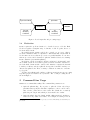
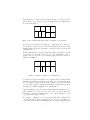
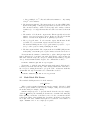
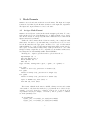
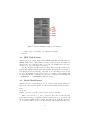
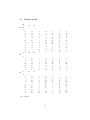
Makeflo User’s Guide
Center for Simulation of Advanced Rockets
March 18, 2004
1
Introduction
1.1
Goal and Scope
The goal of this guide is to allow users to create input files for the structuredgrids fluid dynamics solvers in the Center for Simulation of Advanced Rockets
coupled physical simulation code. This document describes Makeflo, a small
command-line utility program used to create structured-grids input files.
This document describes the inputs required by Makeflo, the purpose and
results of Makeflo, and the outputs produced.
1.2
Related Documents
• Makeflo Developer’s Guide
• RocfloMP User’s Guide
• Rocflo User’s Guide
• Gridgen(tm)
1.3
1
User’s Manual, http://www.pointwise.com/
Summary
Makeflo reads a serial mesh, for example, as generated by Gridgen, splits the
mesh into a user-specified number of pieces, and writes out the resulting mesh
pieces and a topology file describing how the pieces fit together. The mesh
pieces and topology files can then be passed to a structured-grids solver such as
Rocflo. Makeflo is a necessary step in any structured-grids rocket simulation
run.
1 Gridgen is a commercial gridding product by Pointwise, Inc., which is not in any way
affiliated with CSAR or the University of Illinois.
1
Input Serial Mesh
Split Mesh
Makeflo
Rocflo
External
Boundary
Conditions
All
Boundary
Conditions
Figure 1: Rocflo input files and processing stages.
1.4
Motivation
Rocflo requires the problem domain to be described as a set of blocks. Each
block is a regular, rectangular array of elements or cells. Together, the set of
blocks is called a mesh.
In parallel, Rocflo assigns each block to exactly one processor– that is,
blocks are indivisible units of computation. This means that a mesh with 16
blocks cannot use more2 than 16 processors of a parallel machine. To use more
than 16 processors, the blocks must be split into smaller blocks before running
Rocflo. Makeflo performs this splitting.
In addition, each block requires boundary conditions– both internal boundaries, which describe how block fit together; as well as external boundaries between the fluid domain and the outside world. Makeflo computes the internal
boundary conditions, and also splits the user-specified external boundary conditions as it splits blocks. These boundary conditions are written to a Rocflo
topology file.
Together, the splitting and boundary condition generation form a pre-processing
step that prepares a mesh for use by Rocflo. The overall processing flow is
shown in Figure 1.
2
Command-Line Usage
Makeflo is a command-line utility. The command-line parameters are:
1. Optional -splitaxis flag. If you prefer to split the blocks only along a
particular axis, specify the axis with “-splitaxis a”, where a is 0 for the i
axis, 1 for the j axis, and 2 for the k axis. The default is to recursively
split along the longest axis, which produces much better results.
2. Optional -splitrcb flag. By default, makeflo shifts partition boundaries to
ensure the best possible load balance. For example, in cutting a 2-block
2 Since several blocks can co-exist on a processor, a 16-block mesh may be used with fewer
processors.
2
input mesh into 9 output blocks, if makeflo allocates 5 output blocks to
the left input, and 4 output blocks to the right input, the resulting mesh
is as shown in Figure 2.
Figure 2: The default partitioning method optimizes for load balance.
Note how the left input block is split into 5 equal-sized pieces. However,
note that the boundary between the left and right input blocks is offset
slightly, which can increase the number of messages sent between the left
and right halves.
If this communication cost is more important than load imbalance, it may
be preferable to divide the blocks in a more conformal manner. The “splitrcb” flag forces blocks to be recursively split down their centers, as
illustrated in Figure 3.
Figure 3: -splitrcb optimizes for communication.
Note that now the left and right block boundaries line up, which should
minimize the number of messages sent. However, note that this mesh
is not as well load balanced as the mesh of Figure 2. In general, meshes
generated with “-splitrcb” will be less well balanced than meshes generated
normally; but will have slightly better communication.
3. Optional -multilevel flag. To use RocfloMP’s multi-level multigrid solver,
pass “-multilevel m”, where m is a positive integer at least 1 that gives
the number of separate, smaller grids to create. By default there is only
one grid, which can have any size.
For example, “-multilevel 2” creates another smaller grid of half the size
on each axis, and requires each input block to have an even number of
cells along each axis. In general multigrid level m requires all input blocks
3
to have a multiple of 2m cells; and will restrict Makeflo to only cutting
along 2m -cell boundaries.
4. The first input mesh file. The input mesh can be in either HDF (.hdf),
Rocflo mesh (.msh), or Gridgen (.grd) formats, as described in Section 3.
The external boundary condition location (.inp) and boundary condition
definition (.bc or .bcmp) files must have the same base name as the mesh
file.
5. The number of blocks in the output mesh. This is typically at least the
number of processors, but may be larger. If there are already at least this
number of blocks in the input mesh, no splitting is performed.
6. The topology file name. To select Rocflo output, this filename should
end with “.flo”; for RocfloMP output, it should end with “.top”.
The standard CSAR pattern for topology file names is “prefix.flo” or “prefix.top”, where prefix is a string identifying the mesh.
7. The first output mesh file. The output mesh can be in HDF (.hdf), Rocflo
mesh (.msh), or RocfloMP .grda or .grdb formats, as described in Section 3.
For RocfloMP, the Makeflo command line to split a Gridgen input mesh
named “labScale.grd”, boundary location file “labScale.inp”, and boundary definition file “labScale.bcmp” into 256 pieces; writing the RocfloMP topology file
“ls.top” and RocfloMP mesh file “ls.grda”, the command line would be:
> makeflo labScale.grd 256 ls.top ls.grda
For Rocflo, to split the same Gridgen input mesh named “labScale.grd”,
boundary location file “labScale.inp”, and boundary definition file “labScale.bc”
into 256 pieces; writing the Rocflo topology file “ls.flo” and Rocflo mesh files
“ls 001.msh” through “ls 256.msh”, the command line would be:
> makeflo labScale.grd 256 ls.flo ls_001.msh
2.1
Mesh Block File Names
The standard CSAR pattern for block file names is:
prefix NNN.ext
Where prefix is a string identifying the run (for example, “labScale”); NNN
is the zero-padded number of the block (for example, “001”); and ext describes
the mesh format (for example, “hdf”).
Makeflo always expects to be given the first block in the series (for example,
“labScale 0001.hdf”); the remaining block names are determined automatically.
When splitting a mesh into a thousand or more blocks, you must should the
4-digit form “0001”; when splitting into less than a thousand you should use
the 3-digit form “001”. Makeflo itself places no restriction on the number of
digits– “0000001” and “1” are completely acceptable.
4
3
Mesh Formats
Makeflo can read and write meshes in several formats. The input and output
formats are determined by the filename extensions on the input and output files.
The input and output formats need not be the same.
3.1
Gridgen Mesh Format
Makeflo can read (but not write) meshes in the Gridgen .grd format. To create
such a mesh: select a model in Gridgen; choose “Export Mesh”; select “Ascii”
and “Double Precision”; and specify a file name. This is the most common mesh
input format used by Makeflo.
Unlike the other formats, all the blocks in a mesh go into a single file with
this format. As such, no special numbering conventions are needed or used,
but the file must have the appropriate extension. Use “.grd” for files written
using ASCII mode, “.grds” for files written using binary single-precision mode,
and “.grdd” for files written using binary double-precision mode. Note that
Gridgen’s binary output files are not compatible across machine architectures,
but binary files are substantially smaller than ASCII files.
In Gridgen, to output a .grd file from the top-level menu choose:
Input/Output (e) ->
Grid Pts Export (8) ->
Block Volumes (4) ->
Name (k) ->
(type in name, ending with ".grd", ".grds", or ".grdd") ->
For .grd:
format == ascii (a), precision == double (d),
For .grds:
format == binary (^b), precision == single (s),
For .grdd:
format == binary (^b), precision == double (d),
style == PLOT3D (2), Done (ent) ->
Pick All (a), Done (ent)
The format of this file is the same for ASCII or binary versions, and consists
of the number of blocks in the mesh, the (i, j, k) dimensions of each block (for
example, “8 15 17”), then the coordinates of the nodes of each block in C
exponential notation (for example, “3.456e-01”). The x, y, and z coordinates
are in the (unusual) order:
do b=1,nBlocks
(((x(i,j,k), i=1,ni(b)),j=1,nj(b)),k=1,nk(b))
(((y(i,j,k), i=1,ni(b)),j=1,nj(b)),k=1,nk(b))
5
Figure 4: Grid Points Export dialog box in Gridgen.
(((z(i,j,k), i=1,ni(b)),j=1,nj(b)),k=1,nk(b))
end do
3.2
HDF Mesh Format
Makeflo can read or write meshes in the HDF4 Single-File Scientific Data Set
(DFSD API) format. This format is binary, double precision, and platformindependent. Note that these files do not write the CSAR hdf block header,
and hence are not yet readable by Rocketeer.
The file extension for this format is “.hdf”. Each block is contained in a
separate file, with the numeric part of the filename indicating the block number.
You always provide the filename of the first block, and must provide enough
zeros in the filename for the largest block—for example, when writing 5000
blocks, a filename like “out01.hdf” does not have enough zeros and will fail; but
“out00001.hdf” or “out000001.hdf” will work nicely.
3.3
Rocflo Mesh Format
Makeflo can read or write meshes to Rocflo’s native binary format, which consists of the following fields written to a Fortran unformatted binary data file:
time
ni nj nk
(((x(i,j,k),y(i,j,k),z(i,j,k),i=1,ni),j=1,nj),k=1,nk)
Where time and the x, y, and z arrays are all double-precision floating
point numbers in the local machine’s native format; and ni, nj, and nk are all
integers in the machine’s native format. As such, Rocflo mesh files generated
on one machine will not work on another machine with a different architecture.
6
The file extension for this format is “.msh”. Like HDF, each block of the
mesh comes in its own file, and you provide the filename of the first block.
3.4
RocfloMP Mesh Format
Makeflo can write (but not read) meshes to RocfloMP’s native binary format,
which consists of the following fields written to a Fortran unformatted data file:
time
for each block:
block, ni-1,
(((x(i,j,k),
(((y(i,j,k),
(((z(i,j,k),
nj-1, nk-1
i=1,ni), j=1,nj), k=1,nk)
i=1,ni), j=1,nj), k=1,nk)
i=1,ni), j=1,nj), k=1,nk)
The “.grda” version is ASCII-formatted, the “.grdb” version is Fortran unformatted binary. In both cases, the entire mesh is written to a single file.
7
4
Boundary Condition Formats
Makeflo automatically determines and inserts internal boundary conditions,
which form the boundaries between blocks of a mesh. External boundary conditions, such as the location of the ignition boundary, reflection walls, and outflow
boundaries, must be specified by the user.
The external boundary conditions are described in two steps: first, a boundary location file maps block locations to boundary condition numbers; then a
boundary definition file maps boundary condition numbers into a Rocflo or
RocfloMP boundary condition type and parameters.
Both the boundary location and boundary definition files are found by replacing the extension of the first input file with the corresponding extension.
For example, if the input block file is “test001.hdf”, the boundary location
file must be named “test001.inp” and the boundary definition file must be
named “test001.bcmp” (RocfloMP) or “test001.bc” (Rocflo). Because Rocflo
or RocfloMP handle boundary conditions differently, the boundary definition file
has a different extension and format for each solver, as described below.
4.1
Boundary Locations
The only supported format for boundary locations is Gridgen .inp format. To
export this format from Gridgen: choose “Boundary Conditions”, then “Export
Database”.
The .inp format is line-oriented ASCII. The first line is the Gridgen solver
number (always “1”, for the generic solver). The second line gives the number
of blocks in the mesh. The remainder of the file consists of descriptions for each
block.
The first line of a block description gives the (i, j, k) dimensions of the block.
The second line gives the block name, as a human-readable ASCII string. The
third line gives the number of distinct boundary conditions applied over the
block– typically 6 (one per face), but can be as large as desired. Makeflo fully
supports sub-block boundary conditions.
Each boundary condition begins with a line that gives the 1-based i, j, and
k spans covered by the condition; and then a boundary condition number. For
example, a number 5 boundary condition over the large-i face of a 8x11x17
block would be described by the line “ 8 8 1 11 1 17 5”. A number -1 boundary
condition describes an internal boundary, and is followed by an extra line which
Makeflo ignores. All other boundary condition numbers are described by a
single line.
See Section 5.3 for an example boundary location file.
4.2
RocfloMP Boundary Definition .bcmp
A RocfloMP boundary definition file maps Gridgen boundary condition numbers
to RocfloMP boundary condition numbers. The boundary definition file has
extension “.bcmp”, and is typically written manually by the user.
8
This is a line-oriented ASCII text file. The file consists of a sequence of
definitions, each of which fits on a single line. For example, the line:
5 10 1
Lists the mapping between
• The input file boundary condition number, here 5 for a Gridgen inflow
• The output RocfluMP boundary condition number, here 10 for a RocfloMP
burning surface
• Flag indicating this boundary type should participate in mesh motion,
here 1 for a moving boundary
Any line starting with ‘#’ is a comment and hence ignored. See Section 5.1
for a complete RocfloMP boundary definition file.
The RocfloMP boundary definition file and the Rocflo boundary definition
file (described below) have different formats. This is because the RocfloMP .top
file requires different information from the Rocflo .flo file.
4.3
Rocflo Boundary Definition .bc
A Rocflo boundary definition file maps Gridgen boundary condition numbers
to Rocflo boundary condition types and parameters. The boundary definition
file has extension “.bc”, and is typically written manually by the user.
This is a line-oriented ASCII text file. The file consists of a sequence of
definitions, each of which describes a single boundary condition number. An
’@’ character begins a new definition, and is followed by the Gridgen boundary
number to be described. For example, the definition for Gridgen boundary
condition number 8 would begin with a line containing “@ 8”.
The remainder of a definition consists of plain text that is copied directly into
the .flo file except for the ’$’ character and the ’#’ character. A ’$’ character
is replaced in the .flo file by the coordinates of the location of the boundary
condition in the current block. A ’#’ character at the start of a line begins a
comment line, which is ignored. The ’#’ character is special only at the start
of a line. Empty lines are also ignored.
Each block begins with the definition of the special number -1, which defines
the fluid initial conditions and which must be present. Boundaries for which no
external boundary condition is specified (for example, because no .inp input file
was available) are given boundary number 0 by default. These numbers, and
any other boundary number referenced in the .inp file, must all be defined in
the boundary definition file.
4.3.1
Example Rocflo Boundary Definition
A typical section in the boundary definition file, then, is:
9
# Gridgen boundary number 8-- "generic #1"
#
Models the fuel face at the head end.
@ 8
119 $
! Ignition boundary
2855.
FIXGRD
IGNITION
NO_TURB_WALL
119 is the Rocflo boundary condition number, the ’$’ gets replaced with
the location of the boundary, and the remaining lines are parameters for the
boundary condition. See the Rocflo user’s manual for a detailed description of
the acceptable boundary condition numbers and their parameters.
The above definition would expand to the following text if a number 8 boundary was encountered on the small-i face of an 8x12x16 block:
119 1 1 1 12 1 16
2855.
FIXGRD
IGNITION
NO_TURB_WALL
! Ignition boundary
See Section 5.2 for a complete Rocflo boundary definition file.
10
5
5.1
Sample Files
Sample RocfloMP .bcmp file
# RocfloMP boundary condition types for fluid dynamics
# Center for Simulation of Advanced Rockets
# University of Illinois at Urbana-Champaign
#
##################################################
#Gridgen type 2-- "solid surface"; map to slip wall
2 60 0
##################################################
# Gridgen type 5-- "inflow"
# This is an ignition boundary-- a burning surface
5 10 1
##################################################
# Gridgen type 6-- "outflow"
# This is a supersonic/subsonic exit
6 20 0
################################################
# Unspecified condition (default)
0 999 0
##################################################
# Gridgen type 8-- "generic #1"
# Currently used to model fuel face at head end. Change
# these BC to be whatever type is desired to either allow
# burning or inhibit this fuel surface.
8 10 1
5.2
Sample Rocflo .bc file
# Boundary condition types for fluid dynamics
# Center for Simulation of Advanced Rockets
# University of Illinois at Urbana-Champaign
#
###################################################
# These are the initial conditions of the fluid:
@ -1
5 100000. 293. 0. 0. 0.
! number of vars, initial: pressure, temp, velocities
1. 1. 1. 1. 1.
! Reynolds’ number and reference values
1 1 1 5
! Diagnostics to write out each step
11
0 0 0
! Adaptive mesh control (disabled)
##################################################
#Gridgen type 2-- "solid surface"
@ 2
16 $
##################################################
# Gridgen type 5-- "inflow"
# This is an ignition boundary-- a burning surface
@ 5
119 $
! Ignition boundary
2855.
FIXGRD
NO_IGNITION
NO_TURB_WALL
##################################################
# Gridgen type 6-- "outflow"
# This is a supersonic/subsonic exit
@ 6
25 $
! Supersonic/subsonic exit
100000.
#################################################
# The user is expected to go in later and fix these
# unspecified conditions using the fix_bc.sh script.
################################################
# Unspecified condition (default)
@ 0
%bc_unspecified% $
! External BC %bc_unspecified_desc%
%bc_unspecified_params%
12
5.3
Sample .inp file
1
141
8
Block1
6
-1
-1
-1
-1
1
15
8
1
-1
-1
8
8
15
BA
6
1
1
1
15
15
1
1
15
FD
6
1
1
1
1
1
15
15
-1
-1
1
17
17
-8
-8
-8
-8
1
15
8
1
-8
-8
1
1
17
1
1
1
1
1
1
1
1
1
1
17
1
17
1
17
1
17
17
17
17
1
1
17
1
1
17
17
1
-17
-17
-17
-17
1
1
-17
-1
1
1
17
17
-1
-1
-1
-1
17
17
-1
-17
-1
24
-1
26
-1
117
-1
2
-1
25
-1
27
1
1
1
1
1
1
17
17
17
17
17
17
1
17
1
17
-17
-17
17
1
17
1
17
-1
-1
1
17
1
2
2
-1
136
6
2
2
-1
-1
-1
-1
-1
-1
1
1
15
15
-15
-15
-15
-15
-15
-15
15
1
15
15
1
17
17
1
1
1
1
1
1
1
1
17
17
1
17
17
17
17
17
17
-1
132
-1
130
-1
129
8
-1
125
2
17
15
15
1
15
15
15
15
15
17
15
15
15
15
1
15
15
-15
-15
15
...file continues...
13