1
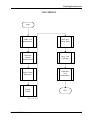
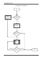
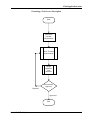
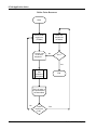
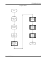
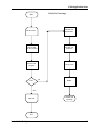
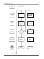
ICAM Application Notes
ICAM Application Notes
Series 2040 Test System
1
ICAM Application Notes
INTRODUCTION
The purpose of this document is to aid the application engineer in taking an in-circuit test
project from its inception to completion. These notes are generic enough to be used in most
projects. They include project essentials, such as generating a test specification and process
description, and include fixture creation and testing using the UniSoft 2000 and AutoGen
software packages.
An application engineer should benefit from some or all of these notes in developing a test
strategy for whatever project they are assigned to.
2
Series 2040 Test System
ICAM Application Notes
Table Of Contents
INTRODUCTION .................................................................................................................... 2
APPLICATION OVERVIEW ...................................................................................................... 5
Generating a Test Specification ..................................................................................... 5
Generating a Test Process Description ........................................................................... 5
Tester Resources ........................................................................................................... 5
Fixture Design............................................................................................................... 5
Write and Debug Tests .................................................................................................. 6
Verify Test Coverage ...................................................................................................... 6
Test Repeatability .......................................................................................................... 6
TEST STRATEGY ...................................................................................................................... 7
Generating a Test Specification ..................................................................................... 8
Generating a Test Process Description ........................................................................... 9
Define Tester Resources .............................................................................................. 10
Design the Fixture ....................................................................................................... 11
Write and Debug Tests ................................................................................................ 12
Verify Test Coverage .................................................................................................... 13
Test Repeatability ........................................................................................................ 14
PROCEDURES ....................................................................................................................... 15
GENERATING A TEST SPECIFICATION ....................................................................... 15
GENERATING A TEST PROCESS DESCRIPTION .......................................................... 15
TESTER RESOURCES .................................................................................................. 16
FIXTURE DESIGN (Using UniSoft Factory 2000 & AutoGen) ........................................ 16
Preparing Files for AutoGen Import .................................................................. 16
Import Files Into AutoGen ................................................................................ 23
Fixture Manufacturing File Requirements.......................................................... 24
FIXTURING NOTES: .............................................................................................................. 26
Fixture Status Wiring ................................................................................................... 26
Matrix Relay Bus Wiring .............................................................................................. 26
Matrix Relay Measurement Boards .............................................................................. 27
Fixture ID and Kelvin Boards ....................................................................................... 28
Kelvin Matrix Relay Channel Wiring ............................................................................ 29
Connecting the Fixture to Earth Ground ...................................................................... 29
Verify Test Fixture........................................................................................................ 29
WRITE AND DEBUG TESTS ................................................................................................... 30
Nets Tests ................................................................................................................... 30
SHORTS TEST ............................................................................................................ 30
SHORTS TEST PARAMETERS ...................................................................................... 30
PARTS TESTS .............................................................................................................. 32
VERIFY TEST COVERAGE............................................................................................ 33
TEST REPEATABILITY .................................................................................................. 33
Series 2040 Test System
3
ICAM Application Notes
4
Series 2040 Test System
ICAM Application Notes
APPLICATION OVERVIEW
Generating a Test Specification
The product’s test specification is the central document around which the entire in-circuit test is
written. Digalog personnel cannot begin work on an in-circuit test application without a
complete test specification. This document is a product-specific publication usually generated by
the manufacturer of the product. It contains a list of objectives, procedures, and requirements
for testing.
Generating a Test Process Description
The largest amount of code within an in-circuit test program may be attributed to the need to fit
within the customer’s manufacturing process. This code, commonly called an “Executive,”
allows the tester to interface with the operator, handling equipment, and information systems.
Failure to clearly define what is required before starting to write the in-circuit test is almost a
guarantee of having to rewrite or heavily modify this section of code. For this reason, it is
necessary to have the test process defined before going any further.
Because of the large amount of resources that are invested into an Executive, many companies
develop a standard software library that may be used. Digalog Systems provides such a library
with its standard AutoGen software package.
Tester Resources
The process of allocating tester resources to achieve the goals set out in the test specification and
the process requirements dictates that the programmer review each test and determine what
part of the tester is going to be used. To fulfill each test specification listed, a sequence of tester
operations is executed. These “test sequences,” if properly documented, may serve as the
pseudo code or model for the actual code to be written when the in-circuit test program is
developed.
Once all of the test sequences have been determined, the hardware configuration of the tester
may be reviewed. If additional hardware is required but not available, some of the test
sequences may have to be modified. If this is not possible, the tester resources will have to be
increased.
Fixture Design
Fixture design should always follow good documentation practices. Complete up-front
documentation will ensure customer satisfaction. Poor documentation on a single fixture may
result in selling only one test system to a customer. Every customer looks at a test system and
fixture supplied by Digalog as one product. In order to repeat that product, proper engineering
practices must be adhered to.
AutoGen, Digalog’s test development environment, can provide accurate fixture documentation
in the form of a net list and wirelist.
Series 2040 Test System
5
ICAM Application Notes
Write and Debug Tests
This procedure should be a relatively straightforward part of the whole project. Difficulties are
usually due to errors and/or lack of definition in earlier phases of the project. Again, good
engineering practices should be followed throughout this phase of the project. As a minimum:
1) It is required that all programs written by Digalog personnel in Visual Basic™ adhere
to the Visual Basic Style Guidelines published by the Digalog engineering department.
2) It is required that all programs written by Digalog personnel be spell checked and
formatted with the VB Polisher program. Settings for this program may be obtained from
the engineering manager.
3) It is required that a version control system be used as an integral part of the software
development process at Digalog Systems (i.e. use on a daily basis rather than when the
project is completed). This version control system must be RCS compatible with the inhouse version control system being CVS.
Comments for the code being written should be clearly understandable by the customer. It is the
desire of Digalog that the customer maintain his own test programs, rather than have Digalog
maintain them.
Verify Test Coverage
This part of the application software procedure is designed to prove that the test really does
work. It is a way to insure that tests that are written will fail when they should. The scope of this
part of the test needs to be discussed with the customer as it could involve a great deal of time
and resources. For example:
A product has 25 components on it. It is desired to make sure that if a component is omitted,
the product will fail the functional test. Twenty-five products must be made, each with a specific
part missing, and tested to ensure this will happen. An alternative would be to have someone
remove and replace each part. As a second phase of this part of the project, the customer
desires to make sure that all open pins are detected. Boards are made to have one open pin ...
This part of the application software procedure is one of the most crucial to get defined up front.
It defines what “completed” means to this project. Once the test coverage goals are met, the
project is almost over. All that remains is repeatability.
Test Repeatability
The last thing to discuss is test repeatability. This portion of the project will help insure that the
customer won’t be calling every few days wondering why a certain part of the test program fails
with borderline values. By examining the variance of the test values of each test, the program
can be made more robust by applying that knowledge to the limits chosen.
6
Series 2040 Test System
ICAM Application Notes
TEST STRATEGY
Start
Obtain Test
Specifications
Write and
Debug Tests
Determine
Process
Requirements
Verify Test
Coverage
Define Tester
Resources
Determine
Test
Repeatability
Design
Fixture
End
Series 2040 Test System
7
ICAM Application Notes
Generating a Test Specification
Start
Obtain
purchase order
to write test
application
No
Test
specification
exists?
Yes
Review test
specification
Modification
necessary?
No
Yes
Write test
spec.
Rejected
8
Get customer
approval
Approved
End
Series 2040 Test System
ICAM Application Notes
Generating a Test Process Description
Start
Determine
process
requirements
Write "Process
Requirements"
Design
graphical
user
interface
Get customer
approval
Rejected
Approved
End
Series 2040 Test System
9
ICAM Application Notes
Define Tester Resources
Start
Define tester
resources
(TRMan)
For each test
in the test
sequence ...
Have test
sequences
reviewed
No
O.K.?
Yes
Write the
test
sequence
description
End
Until all tests in
the specification
are described
No
10
Tester
resources
O.K.?
Yes
Series 2040 Test System
ICAM Application Notes
Design the Fixture
Start
Obtain CAD
Files
Wire
Fixture ID
Run UniSoft
Software
Wire
Matrix
Relay
Buses
Run
AutoGen
Software
Verify
Test
Fixture
Send
Appropriate
files to Fixture
House
End
Series 2040 Test System
11
ICAM Application Notes
Write and Debug Tests
Start
For each test
sequence
defined
Review test
specification
Generate Nets
Test & Parts
Test
as applicable
review test
sequence
Next test
sequence
Review code
Run tests on
product
Modify
No
Pass?
Yes
End
12
Series 2040 Test System
ICAM Application Notes
Verify Test Coverage
Start
For each test ...
Review test
specification
Insert a fault
into the product
Review test
sequence
Run the test
program
review code
No
Fail?
Modify
Yes
Next test
Restart test
coverage
End
Series 2040 Test System
13
ICAM Application Notes
Test Repeatability
Start
For test run
1 to 5
Calculate
standard
deviation of test
Review test
specification
Log data
Compare
nominal –3 SD
against test
limits
Review test
sequence
No
Next test run
Good??
Review Code
Yes
14
For each test ...
Next test
Modify
Extract
data from
logs
Done
Restart test
repeatability
Series 2040 Test System
ICAM Application Notes
PROCEDURES
GENERATING A TEST SPECIFICATION
As mentioned before, a test specification is a document containing a list of objectives,
procedures, and requirements for testing each individual product. Many variables besides testing
the actual product need to be considered. These include available resources, budget
considerations, time schedule, type of testing, and level of electronics to be tested, etc.
In addition, consumer requirements must be included. These include reliability, complexity of
repair, volume, Y2K compliance, and even ISO 9000 compliance. All of these variables and
more must be considered and included in a test specification. A general specification will not
suffice in most cases since testing on some products may lack required capabilities and testing
on other products may be too expensive and complex.
For these reasons, each test specification should be a product-specific solution to testing needs.
GENERATING A TEST PROCESS DESCRIPTION
The first step in generating a test process description is determining which parts of the product
need to be tested, and the best way to test each individual part. In some cases, a simple “shorts”
test may suffice. For other parts, specific values need to be measured. For this reason, Digalog
has developed a “Test Executive” which is flexible enough to include a vast variety of test
schemes including everything from single resistors to complex RC networks and ICs. The
executive also provides an interface to the operator, automated material handling equipment,
and information handling systems such as networks and/or data collection devices.
Generate a test process description as follows:
1) Classify parts by type, such as R Resisters), C (capacitors), D (diodes), Q (transistors),
etc.
2) Determine a test method for each device type, and the required accuracy such as:
R=
C=
D=
measure ohms
measure capacitance
check polarity
check leakage
measure forward drop
measure reverse breakdown voltage (Zener)
etc.
By carefully writing the process description, extensive modification in later steps of the
application can be avoided. In addition, software libraries can be developed for use in future
projects. When the test process description is completed, the executive may be modified to suit
the individual needs of the manufacturer.
Series 2040 Test System
15
ICAM Application Notes
TESTER RESOURCES
Now the programmer must review each individual test and determine if the tester resources are
adequate to properly test each component. These tester resources include:
1) ICAM specifications.
2) Functional test resources.
The tester resources can be defined using Digalog’s TRMAN software (see Tester Resource
Manager in the 2040 Maintenance Manual PN#4200-0163). This program will investigate the
test system and determine all of the resources in the Testhead and what power supplies are
present. Once this is accomplished, each individual test or test sequence can be defined.
1) Compare the parts test process requirements to the ICAM test specifications, and note
any exceptions.
2) Determine if the available functional test resources will resolve these exceptions and
note specific methods where applicable.
3) If it is determined that some components cannot be tested using the current
resources, the test process may be modified to utilize the current hardware.
A) Determine new test methods using existing hardware.
B) If this is not realistic, the tester hardware may need to be increased to include
these components.
C) Change the requirements by expanding the tolerances, or skip the part test
entirely.
Once this step is completed, the tests or sequence of tests can be used as the basis for the actual
code used in the in-circuit testing.
FIXTURE DESIGN (Using UniSoft Factory 2000 & AutoGen)
Preparing Files for AutoGen Import
Before any testing scheme or fixture design can be implemented, the UUT CAD, BOM, and
Parts information must be put into an importable format. This section will walk you through the
process of designing a fixture with the UniSoft Factory 2000 and Digalog AutoGen software.
Create a project folder
Open AutoGen and create a new project so that AutoGen can create the project folder
structure. The Hardware dialog box will be displayed. Enter the MRly and Fixture ID
information. If you’re unsure about the current configuration of the tester, use TRMan to
display the information. If the project is being created on a development computer not
16
Series 2040 Test System
ICAM Application Notes
attached to a 2040 Test System, use the Manual Configuration feature of TRMan to
register the proper configuration.
Save the project “As” the desired project name. A messagebox will appear advising you
that the project is not an AutoGen project, and would you like to create one. Click “Yes,”
then close AutoGen.
Create a CAD folder
Use the Windows™ Explorer to create a \CAD folder under the
\Digalog\Projects\<projectname> folder. Note that AutoGen has already created an
\AutoGen folder for you.
Add new CAD data to the folder
Copy the output file from your CAD system, the BOM (Bill of Material) text file, and the
Parts List text file for your project into the newly-created \CAD folder. The UniSoft
Import dialog supports the following formats:
Factory 2000 Files (*.F2B)
Board Files (*.F2B)
Property Files (*.F2P)
ICP-D-356 Files (*.356)
PADS Files (*.ASC)
GENCAD Files (*.CAD)
CAD-Star Files (*.CDI)
Old Cells/Fixture Files (*.CFF)
AutoCad Files (*.DXF)
FabMaster Files (*.FAB)
Fab All Files (*.FBA)
Gerber Layer Files (*.GER)
HPGL Files (*.HPG)
Intergraph Files (*.LST)
OrCad Files (*.MIN)
Mentor Neutral Files (*.NEU)
Accel Tango Files (*.PCB)
Accel PCAD Files (*.PDF)
Protel Files (*.PRO)
Valid Allegro Files (*.VAL)
Veribest Files (*.VRB)
Cadon Files (*.XED)
NOTE: Factory 2000
uses the file extension to
determine the import
method. If your CAD data
uses a different
extension, rename the
file as needed.
The format for the BOM file must conform to the format specified in the [BOM] section
of the digalog.ini file located in your \Windows (Windows 95) or \Winnt (Windows NT)
folder. This file is installed on your computer when the UniSoft Factory 200 software
package is installed. The [BOM] section should be manually modified if necessary to
match the specific BOM format for whatever type of file is being imported. A sample
[BOM] format is shown on the next page:
Series 2040 Test System
17
ICAM Application Notes
[BOM]
Style=Tabs
PartNo=1
Quantity=2
RefDes=3
User1=0
User2=0
User3=0
User4=0
Note that this is a tab-delimited text file (Style=Tabs) with the field name first and the
field position after the “=” sign. The following is a sample section of a matching BOM
file:
PartNo Quantity
1500-1300
4
1500-1321
12
1500-1322
6
1500-1390
2
1500-1400
7
1500-1405
4
1500-1410
2
1500-1416
2
1500-1426
4
RefDes
C194,C199-C200,C205
C115,C121,C123,C132
C66,C70,C73,C76,C212,C217
C74,C77
C48,C54-C58,C69
C184,C186,C189,C191
C213,C216
C214-C215
C1-C4
The Parts List file must be in the format of a tab-delimited text file with the first field
containing the in-house part number, the second field containing the nominal value to be
measured, and the third field containing the plus and minus test tolerances separated by
a comma. For example, a 10uF, +80% / -20% capacitor with a part number of 15001300 would be entered as:
1500-1300
10uF 80,20
A section of a sample file is shown below:
Partnumber
1500-2030
1500-3020
1500-1300
1500-1304
1500-1305
1500-1310
Value
0.1uf
10uf
5.6pf
8.2pf
10pf
10pf
Tolerance
20,20
20,20
10,10
6,6
10,10
10,10
The tolerance field should reflect the test tolerance, not the part tolerance. For example,
a 10K, 5% resistor should be tested with a 7% tolerance. 5% for the part, and 2% for the
test.
18
Series 2040 Test System
ICAM Application Notes
Ideally, this would take the form of a “master” parts list containing all the electronic parts
used in all of the products of your company, so that the list can be used in every
AutoGen project created.
At this time, the Tester Resource requirements should be reviewed to ensure that
enough MRly channels are present for additional nets and Kelvin channels. Also
note, some components (such as transistors tested as two diodes, ICs, etc.) may
require additional channels to be properly tested.
5) Open the “Unisoft PCB-Test for Digalog” program from the Unisoft Factory 2000
program group. From the File Open dialog, select the proper filter (filename extension)
for your CAD file, then navigate to the folder \Digalog\projects\<projectname>\CAD
and select the CAD file for your project. If you receive a message stating that a “traces”
file is missing, just cancel the message box. The program will import your CAD file and
display a textbox which reports any errors or discrepancies in the import process. If errors
are displayed, they may need to be corrected later. You can save the errors to a file for
reference.
6) From the File Options dialog (shown below), select the Misc. Settings tab and set the
maximum character length for net names. A value of 20 is usually sufficient, but check
your CAD file to be sure that you set a sufficient length and no net names are truncated.
7) Open the Renumber Nets dialog from the Edit menu to define the minimum and
maximum valid net numbers. The Minimum net number should be set to 1 in order to
reserve “0” for the fixture probe channel, and so that net numbers are mapped to
corresponding numbered MRly channels. The maximum should be set to the highest
Series 2040 Test System
19
ICAM Application Notes
MRly channel.
8) From the Renumber Nets dialog, scroll
through the list of nets and locate the ground
net. Assign net #1 to it. This will make the
Test Debug process easier by forcing the large
nets to the “front” of the line. You may also
wish to assign 2, 3, and so forth to other large
multiple-node nets like power buses.
9) If there were any errors displayed during
the CAD file import process, you may need to
edit the properties of the affected
components. Use the error file from step #5
as a part number reference. From the Edit
menu, open the Find dialog. Go to the Part#
and locate the desired part, then click Apply. Open the Edit Properties dialog, click the
Details tab, and make whatever changes are needed.
An example might be a connector that mounts on the solder side but is not actually
attached until after the in-circuit test is done. “PCB-Test for Digalog” may report a
potential probe point as being inaccessible because it is located underneath the
connector. You will need to edit the connector properties to “lie” to the program and
change the connector to a topside mount (uncheck the Bottom Side box) so the program
“knows” that the probe points are available.
10) Your original CAD file may contain the bill of materials (BOM) information already.
In order to import your BOM file, click the “Clear BOM Data” under the Edit menu,
then click “Import BOM File.” Locate your BOM file in the dialog box and import it. If
any errors are reported, such as duplicate parts or parts in the BOM but not in the CAD
file, you must investigate and correct them.
11) At this time, save the file, <filename>.F2B, in the CAD directory. The .F2B file is
the principal file produced by PCB-Test for Digalog and encapsulates the entire project
up to this point. It can be used here or with the UniSoft Viewer as a tool to examine
every aspect of the board on-screen.
12) From the File Export menu, select “To Pronto Fixture.” The “Pull to RefDes” dialog
will appear. Enter the reference designators for the part types which should be given
priority when Pronto Fixture assigns nodes to receive pogo pins in the fixture. The
reference designators MUST be the same as your
CAD file, and are CASE SENSITIVE. For example, if
you want Pronto Fixture to assign the pogo to an IC
pin, to a resistor pin, to a capacitor pin, or to a VIA
on the board, you would enter:
U, R, C, VIA
20
Series 2040 Test System
ICAM Application Notes
This assumes that ICs in your CAD file are designated by the letter U, resistors by R,
capacitors by C, and VIAs by VIA. Click OK when done.
13) The Save As dialog will now appear. Specify <projectname>.xed as the filename
and save the file in your project’s \CAD directory.
14) The Pronto Fixture window should now open as Pronto imports the file. When the
import operation is completed, select Options |
Nail Rank. The resulting dialog box will display
the criteria which Pronto will use in deciding
which node on each net it will “nail” with a probe.
The “1” criterion receives preference. A “0”
means that a node type will not be nailed under
any circumstances. Since surface mount nodes
(generally not desirable for nailing) are 0 by default and the previously designated “pull”
nodes are 1, it may be best to simply accept the defaults.
15) Now open the Options | Probe Spacing dialog. By default, Probe Space [1] should
be 100, [2] should be 75, and [3] should be
50. This means that Pronto will attempt to
place pogo pins no closer than 100 mils (0.1
inch) apart if it can do so. If not, it will try to
maintain 75 mils, and if not, 50 mils. Due to
the small size and fragile nature of the
required probes, it is best not to attempt
smaller spacing.
16) Pronto will attempt to place a nail (probe) on every net, using your specific criteria
as its guidelines. Any nets which cannot be nailed without violating the criteria will be
reported after the nail assignment operation. Open the Options | Analysis Filter dialog.
This dialog allows you to specify the reasons to be included in the report. As a general
rule, all reasons except “< 5 pins” should be selected.
17) Finally, open the Options | Automatic selection. The nail rank criteria dialog box
will be displayed once more, allowing you to confirm your choices or make changes.
Click Accept and Pronto will begin the process of assigning probes (“nailing the nets”).
This will take some time, depending on the size and complexity of your board.
18) Once the nailing process is complete, open the Fixture | Fixture Analysis dialog to
check and see if any nets could not be probed and if so, why not. Nets may not be
probed for a number of reasons. In the on-screen display, red points represent probe
locations and yellow points represent nets that were not probed. To further investigate
individual nets and probes, click on the Selection tool in the toolbar (resembles a target),
then click on the node of interest. All nodes connected to that same net will turn white. If
all of the nodes on that net were yellow, the net is not probed. Further information is
displayed in the white bar at the bottom of the screen.
Series 2040 Test System
21
ICAM Application Notes
19) If any nets are not probed, you may need to modify your probe spacing criteria in
Pronto (Step 15) and/or your reference designator “pull” list in PCB-Test for Digalog (Step
12), and the repeat the probe placement procedure (Step 16). The specific steps will
depend on the exact nature and complexity of your project.
20) Once you are satisfied with the probe placement, select the Build | Fixture Build
Files routine. Pronto will build the .FBP file which contains the probe information. This is
one of the principal project files to be imported into AutoGen and be sent to the fixture
house. When this operation is complete, exit Pronto in the normal manner.
21) Once Pronto Fixture exits, you will return to the PCB-Test for Digalog screen. The
next step is to import the probe information created by Pronto. Select the
<projectname.FBP> file from the Import Probes dialog and click OK. The dialog will
close and the import process will begin. This procedure will take several minutes, during
which time the program will give absolutely no indication that it is doing anything (a
minor bug which will be fixed in a later release). When the import process is complete,
the Importing Probes text message box will appear showing the number of probes
imported. Click Close to exit this box.
22) You should now save the <projectname.F2B> file again in order to merge the
imported probe information from Pronto with the original CAD file information. It is a
complete project file and can be viewed in the free UniSoft viewer or in the PCB-Test for
Digalog software.
23) Open the Digalog | Create Wirelist dialog to generate the .NET wirelist, which is
one of the two files AutoGen will eventually import from UniSoft (the other is the .FBP
probe file which was created by the Pronto Fixture program). Select the “Include Parts...“
checkboxes. If you intend to use VIAs as probe points, select them also. If not, leave this
box unchecked. This will hold down the size of the list. Use the Browse button to locate
your parts library, then click OK. At this time, open NotePad and visually inspect the Net
List. Any parts that are not correctly formatted here indicate that the part is missing from
the library. The only other place that parts are checked is at AutoGen | Import. After a
brief delay, the Digalog Output File
dialog box will open, offering to save
the file as <projectname>.NET in the
\CAD folder. You may save it here or
navigate to the AutoGen folder and save
it there. You should receive a report
dialog stating the number of
components, nodes, and nets which
qualify.
24) You are now finished with the Unisoft portion of the project generation. Exit UniSoft
and open AutoGen.
22
Series 2040 Test System
ICAM Application Notes
Import Files Into AutoGen
Open AutoGen and select File | Open. The listbox to the right should
appear with a directory listing of the available projects in the
\Digalog\Projects directory. Select the desired project from the dialog. If
the project is not an AutoGen project, a prompt appears to create one. If
the project was already created as an AutoGen project, disregard any
error messages about one line files and continue.
From the File menu, click on Import and a listbox will appear with the
<projectname.net> file in it. Select this file to create the parts and nets
lists in AutoGen. A Hardware dialog box should appear to assign Matrix
Relay boards for Measurement or Kelvin. Usually on a system with four Matrix Relay boards, #0
to #2 would be assigned for measurement and #3 would be used for Kelvin. Each project’s
requirements will vary. Check the net count from the Factory-2000 program to ensure that
enough MRly boards (64 channels/board) are assigned as Measurement Boards.
For example, the net count is 137. This requires that MRly boards 0, 1, and 2 are assigned as
measurement boards. If the net count is 192 or higher, additional MRLY boards need to be
assigned for measurement. In addition, at least one MRly board should be designated as Kelvin.
If enough measurement or Kelvin channels are not present, AutoGen will flag error messages in
the Log Window for measurement or Kelvin nets that could not be assigned channels when
channels are assigned as instructed below.
The Part Editor should now contain all of the parts in the project. From the Nets tab, select
“Assign Channels” and “Read Probe.” From the listbox, select <projectname.fbp>. When the
Hardware dialog pops up again, click OK. Now select File | Save As. Under \Digalog\Projects
select <projectname> and click OK. When the prompt appears about replacing files, click OK.
The ICAM board provides 16 patchboard pins to create the identification code for the test
fixture. The 16 fixture ID pins are in the left and right columns of rows 23 through 30 on the
ICAM board. They are used to represent a 16 bit hexadecimal number that identifies the test
fixture. They are labeled as FID0 through FIDF on the patchboard map. See the patchboard
map to get the bit number associated with each patchboard pin. The pin labeled FID0 is the
lowest significant bit of the hexadecimal number and pin FIDF is the most significant bit. This
hexadecimal number representing the fixtures ID can be read with the ‘FixID()’ functional call.
Any fixture ID pin connected to a digital ground patchboard pin on the ICAM board will be read
as a 0. Fixture ID pins that are not connected to digital ground will be read as a 1. Therefore,
to wire the fixture to have an ID of 0xFFEE, fixture ID bits #0 (FID0) and #4 (FID4) would be
connected to digital ground and the rest would be left alone. The digital ground patchboard
pins are labeled as DGND in the patchboard map. Typically, the Fixture ID is the last 4 digits of
the part number of the DUT.
Lastly, open File | Wirelist. When a message appears saying a wire list was created, click OK.
Backup the project and prepare to send the required files to the fixture manufacturer.
Series 2040 Test System
23
ICAM Application Notes
Fixture Manufacturing File Requirements
The files required for manufacturing a fixture are generated by using Digalog Systems’ AutoGen,
Unisoft’s CAD Connect (or Factory-2000), and Unisoft’s Pronto Fixture programs. The purpose
of some of these files is described below according to their file extension.
FBS:
FBR:
FBA:
FB1:
FBP:
FBT:
FDB:
FDT:
The FBS file is a drilling file containing a sorted probe size list and all of the probe hole
locations. It is the standard file used for solder-side fixture fabrication.
The FBR file is a report file listing the net-related problems found by the software while
placing test probes and a summary regarding the required probes and holes, which can
be used in creating the fixture quotation request.
The FBA file is a user-only reference file containing all of the component pin locations
and connection information and is not normally used in the fixture fabrication process. It
may be useful for other applications.
The FB1 file is a user-only reference file containing all of the components sorted by their
reference designator.
The FBP file is a drilling file composed of solder-side and component/top-side
information. It contains a sorted probe size list and all of the probe hole locations.
The FBT file is a drilling file containing a sorted probe size list and all of the probe hole
locations. It is the standard file used for component/top-side fixture fabrication.
The FDB file contains the same information as the .FBS file, but in a different drill format.
The FDT file contains the same information as the .FBT, but in a different drill format.
The remaining files produced by the Unisoft programs are either temporary files used by the
programs themselves or files which are generated during the process in order to be compatible
with earlier versions of CAD Connect and Pronto Fixture if present. To prepare a fixture
quotation, the fixture manufacturer will need the following items:
•
•
•
24
Dimensions of the printed circuit board
FBP file (produced by Pronto Fixture)
LST file (produced by AutoGen)
Series 2040 Test System
ICAM Application Notes
To produce the fixture for solder-side probing only, the fixture manufacturer will also need the
following items:
•
•
•
FBR file (produced by Pronto Fixture)
FBS file (produced by Pronto Fixture)
Fully assembled, stuffed printed circuit board.
To produce the fixture for solder-side and component/top-side probing, the fixture manufacturer
will also need the following items:
•
•
•
•
FBR file (produced by Pronto Fixture)
FBS file (produced by Pronto Fixture)
FBT file (produced by Pronto Fixture)
Fully assembled, stuffed printed circuit board.
It is recommended that the F2B database viewer file (created by CAD Connect) and the board
viewer program EZ-Viewer (Uniview.exe) also be sent to the fixture manufacturer. This allows the
user and the fixture manufacturer personnel to more easily communicate and thus resolve any
problems by using a common file for referencing.
In addition to the standard .lst file, it is recommended that the following be added to the end of
the file:
Banana Jacks:
Place 2 female Banana Jacks through the right side of the fixture:
Wire one Banana Jack to channel 0 (probe channel)
Wire one Banana Jack to DGND
Discharge Resistors
Wire a 100 ohm resistor between Patchboard locations NN14 (SB00) and PP11 (AGND).
Wire a 100 ohm resistor between Patchboard locations NN17 (SB12) and PP11 (AGND).
Wire the Matrix Relay Measurement and Kelvin boards per attached diagram. (Enclose page 25)
Notes:
Digalog 2040 Fixture
ESD top Plate
Plexi Cover
All probes on bottom side
Provide plot with node numbers
Cycle Counter
Silk-screen node numbers
Drill all holes
Two Banana Jacks mounted through pan
Single strand wiring
Include 20 spare probes and sockets for each type used
Include 40 spare interface pins.
Series 2040 Test System
25
ICAM Application Notes
FIXTURING NOTES:
Before any further development can be done, a complete calibration and functional test routine
MUST be completed on the target development 2040 Test System to ensure accuracy and
consistency of the debugging procedure.
Mount the fixture on the target tester and power
the system up. Open AutoGen and load the
<projectname> project. Use the File |
Hardware option to assign the proper Matrix
Relay channels for Measurement and Kelvin. This
dialog can also be used to check the Fixture ID. If
the Fixture ID has not been wired by the fixture
manufacturer, it should be wired now.
Fixture Status Wiring
In addition, the ICAM board provides two patchboard pins used to determine the status of up to
two fixture vacuum wells. The status pin for the first well is in the left column of row 9 and the
status pin for the second well is in the right column of row 9. See the patchboard map to view
their location. The ‘FixStat()’ functional call is used to read the current status of the vacuum
wells. A fixture status pin needs to be brought low to signal the vacuum is engaged for that well.
Please note that when a vacuum well is engaged (the pin is brought low), the ‘FixStat()’
functional call will return a 1 to signal that the well is engaged (i.e. the functional call does not
return the high/low state of the pin itself). A typical wiring method is to have an isolated pad on
the UUT and have two pogo pins that will make contact with the pad when the UUT is
engaged. One of the pogo pins is wired to the fixture status pin for that well and the other pin is
wired to a digital ground patchboard pin on the ICAM board. Therefore, when the UUT is
engaged and both pogo pins are in contact with the pad, the fixture status pin is connected to
digital ground. The digital ground patchboard pins are labeled as DGND in the patchboard
map.
If a switch of some sort is used to signal when the UUT is engaged, it must be wired such that
digital ground is applied to the corresponding fixture status pin when that vacuum well is
engaged.
Matrix Relay Bus Wiring
In addition to connecting a Matrix Relay channel to each of the nodes on the UUT, the four
measurement/source ICAM patchboard pins need to be bussed to each of the Matrix Relay
boards that are assigned to be used as measurement boards. The four ICAM Patchboard pins
are in the left and right columns of rows 33 and 34. The four pins are used for the guard bus,
the current source bus, the measurement bus, and the voltage source bus. In the patchboard
map they are labeled as GrdB, CrSB, MsrB, and VtSB respectively. The connections are made as
follows: The guard bus (left column row 33 on the ICAM) is bussed to the patchboard pin in the
left column row 33 on each of the Matrix Relay boards assigned to be used as measurement
boards. The current source bus (right column row 33 on the ICAM) is bussed to the patchboard
26
Series 2040 Test System
ICAM Application Notes
MRLY #1
(Measurement)
MRLY #2
(Measurement)
Series 2040 Test System
•
•
•
•
•
•
•
•
Row 33
Row 34
SKvn
MKvn
ICAM Board
MRLY #3
(Kelvin)
Row 31
Row 32
Matrix Relay Measurement Boards
MRLY #0
(Measurement)
27
28
Bus2
Bus4
B34
Bus1
Bus3
T34
MRly
T33 B33
34
To MeasAmp via NC Relay; associated w/SBus0
CrSB
VtSB
33
To Guard via NC Relay; associated w/SBus3
GrdB
MsrB
Mkvn VOUT
32
FIDF
Skvn IOUT
FIDE
30
FIDD
FIDB
FID9
31
FIDC
29
FID8
27
FIDA
FID6
26
28
FID5
FID4
25
FID7
FID2 FID3
24
FID1
FID0
23
22 DGND DGND
Wire to Bus 2 of the Kelvin MRly Bd (Source)
KELVIN
Wire to Bus 3 of the Kelvin MRly Bd (Measure)
Range: &H0000 to &HFFFF
(65,536 possible fixture IDs)
To VOUT via NC Relay associated w/SBus1
To IOUT via NC Relay associated w/SBus2
Connected directly to VSource
Connected directly to ISource
16-Bit Fixture ID
(GND = 0)
Digital Ground
Fixture ID and Kelvin Boards
ICAM Application Notes
Series 2040 Test System
ICAM Application Notes
pin in the right column row 33 on each of the Matrix Relay boards assigned to be used as
measurement boards. The measurement bus (left column row 34 on the ICAM) is bussed to the
patchboard pin in the left column row 34 on each of the Matrix Relay boards assigned to be
used as measurement boards. And the voltage source bus (right column row 34 on the ICAM) is
bussed to the patchboard pin in the right column row 34 on each of the Matrix Relay boards
assigned to be used as measurement boards.
Kelvin Matrix Relay Channel Wiring
The source kelvin and measure kelvin patchboard pins on the ICAM board need to be wired to
each of the Matrix Relay boards that have been assigned to be kelvin boards. The source kelvin
and measure kelvin patchboard pins are in the left column of the ICAM board in rows 31 and
32 respectively. See the patchboard map to view their location. The source kelvin will be
labeled as Skvn and the measure kelvin is labeled as Mkvn. The source kelvin pin on the ICAM
needs to be bussed to the pin in the right column in row 33 on each of the kelvin Matrix Relay
boards. The measure kelvin pin on the ICAM needs to be bussed to the pin in the left column
in row 34 on each of the kelvin Matrix Relay boards.
Connecting the Fixture to Earth Ground
The fixture should be connected to earth ground to minimize the effects of 60 Hz noise during
ICAM measurements. This can be accomplished by connecting one of the analog ground
patchboard pins on the ICAM board to the fixture. An analog ground pin will be labeled as
AGND in the patchboard map. The connection to the fixture must be placed at a location that
also comes into contact with the tester’s earth ground. A common location to connect to is the
base of the fixture. The base of the fixture is the framework that holds the fixture’s Patchboard
with all of the pins inserted into it. There usually is a screw that mounts the base to the fixture
well. The connection to the fixture can be made by loosening the screw, wrapping the wire
around it, and then tightening the screw again.
Verify Test Fixture
Open the AutoGen Nets | Shorts Test tabs. The Verify Test Fixture
dialog is displayed. The Probe Channel (usually channel 0 left open
from the fixture design stage) is used to guard (connect to analog
ground) a chosen assigned channel, and the program executes a
Shorts Test when the Probe command button is selected. The channel and net shorted by the
probe should be displayed in the textbox at the bottom of the form. All assigned channels
should be checked in this manner to avoid potential problems in the debugging stage. If no
channel or the wrong channel is displayed, the fixture has a possible wiring problem.
Series 2040 Test System
29
ICAM Application Notes
WRITE AND DEBUG TESTS
Nets Tests
Open AutoGen and open <projectname>. When the Hardware dialog appears, verify the
assignment of the Measurement and Kelvin Matrix Relay boards. Also, verify the Fixture ID
value. Click OK when done. The screen should look similar to the screen displayed below. Since
the fixture has already been verified using the Verify Test Fixture routine (Page 19), proceed to
the debugging routines.
Before any individual parts tests are run, the Shorts/Opens tests on the nets need to be run.
Switch to the Nets tab and the dialog on the next page will be displayed. This dialog is used to
run all of the net tests. Tests on individual nets can be performed by selecting an individual net
from the Net Editor grid and selecting Execute from the Execute menu or using the Execute tool
from the Toolbar. However, before performing any Shorts/Opens tests, select the Shorts Test
subtab to display the Shorts Test Parameters dialog.
SHORTS TEST
This test checks all activated nets for net-to-net shorts. The test is performed by sequentially
measuring the resistance between an individual net and all the other nets.
SHORTS TEST PARAMETERS
The conditions for the test are setup using the
Shorts Test Parameter functions, as shown to the
right.
30
Series 2040 Test System
ICAM Application Notes
Source Voltage - Value of the source voltage to be used during the test. Default value is
300 mV.
Default Test Time - Establishes the default test time for the test.
Current Limit - Establishes the default current limit for the test.
Source Impedance - Sets the source impedance limit for the test.
Max Shorts Resistance - Used to establish the resistance value below which a net short
condition is said to exist. If the calculated Net impedance is greater than this value, this
value is used instead.
Min Opens Resistance - Used to establish the resistance value above which a net open
condition is said to exist. If the calculated Net impedance is less than this value, this
value is used instead.
Shorts Value % - Percentage of calculated parallel resistance to be subtracted when
setting the maximum resistance for a specific shorts test.
Opens Value % - Percentage of calculated parallel resistance to be added when setting
the minimum resistance for a specific opens test.
Min Shorts Threshold - Calculated values below this default will disable the shorts test
for the corresponding nets.
When the Generate Test Parameters command button is selected, AutoGen calculates the
parallel resistance and the sum of the capacitance for every individual net in the project with the
Test Type designated as “Shorts&Opens”. From this calculated value, AutoGen subtracts the
“Shorts Value %” to determine the maximum resistance for a short, and AutoGen adds “Opens
Value %” to determine a minimum resistance for an open. If the maximum resistance for a short
is greater than the default Max Shorts Resistance, the default is used during the shorts test. If
the minimum resistance for an open is less than the default Min Opens Resistance, the default
is used during the opens test. If the maximum resistance for a short is less than the Min Shorts
Threshold, the shorts test is disabled. Typically, the resistance for the shorts and opens values
should be between the shorts and opens thresholds. The test time is determined by the RC time
constant based on the parallel resistance and the sum of the capacitance.
For nets with a Test Type designated as either just Shorts or just Opens, no calculations are
performed, and the shorts and opens thresholds in the Net Editor will remain unchanged. For
nets with high total capacitance, test times for these nets may be increased.
As mentioned above, when the maximum resistance for a short is calculated to be less than the
Min Shorts Threshold, the shorts test is disabled. This prevents the program from designating
two or more nets connected by a resistance less than the Min Shorts Threshold as shorted.
Since the Shorts test and Opens test are automatically run before any parts test, this group of
nets is skipped. To properly test these nets, the ShortsMeas functional call may be placed in a
Series 2040 Test System
31
ICAM Application Notes
user test routine to determine the resistance. Each net in the group may be individually tested
while the other nets in the group are manually unguarded.
The functional call parameters are covered on in the ICAM User Manual, PN#4200-0165, and
the measured resistance values for the group of nets are returned to the programmer in the Log
Window.
As an example, nets 17, 29, and 42 are connected by 4Ω resistors. The resistance is less than
the Min Shorts Threshold and the shorts test for these nets is disabled. From the Net Editor, set
the Test Type for net 17 to User. In the Comment field, enter “NET17.” Open the Basic subtab,
and view the “Proc:” drop-down listbox. Note that a ShortsNET17 and OpensNET17 processes
have been created. Sample code for the User test for net 17 is shown below. Since the
OpenPinCheck for this net is of no significance, the condition flag is set to IPASS.
Public Sub ShortsNET17(sd As ShortsData)
Dim r As Double
Unguard 29
Unguard 42
ShortsMeas r, 17, 0.100, 3, .001
sd.Resistance = r
sd.Condition = IIf(sd.Resistance > 10, IPASS, IFAIL)
Guard 42
Guard 29
End Sub
Public Sub OpensNET17(sd As ShortsData)
sd.Condition = IPASS
End Sub
For more information on the Net Editor,
consult the ICAM User Manual, PN#4200-0165.
PARTS TESTS
After the Shorts Tests have been determined, each individual parts test must
be run and debugged. Individual tests or groups of tests can be run from the
Execute menu. The specific parameters for executing each of these tests may
be “tweaked” or modified from the Part Editor grid. For example, the normal
test time for an individual test from the Test Parameters frame (Parts Parameters) is 1.000mS. However, larger than normal capacitors may take
longer to charge. Obviously, the characteristics of some components will
dictate longer test times or different forcing values. The Graph function can
be used to view the stability and/or range of specific tests.
In some situations, the normal test strategy will not properly test a
component. In these situations, the programmer may need to develop a
User test. From the Parts Editor, select the Test Type cell for the component in question and click
on the down arrow. A drop-down listbox is displayed with the available choices. Select “User.”
32
Series 2040 Test System
ICAM Application Notes
This designates that a user-defined test will be used for that specific component. The specific
name of the used-defined test should also be placed in the comment field. For example, part
Q1 is a transistor. Since testing this component is not covered by the normal set of Test Types, a
User test must be defined. For this part, set the Test Type to User. Under the Comment column,
reference the test as PartQ1. Now open the Basic subtab. Notice, AutoGen has already created
a process for the test. Select the process from the list, and create and save the test. The test will
automatically be run whenever it is within the range determined by the Execute menu.
VERIFY TEST COVERAGE
This is an important part of the testing process. As an example, a 250 component board would
have 250 parts tests executed on it. Ideally, 250 separate boards would be built, each with a
different part missing. Then each separate test would be checked for validity by failing its
respective part on one of the 250 boards. As previously mentioned, an alternative would be to
have someone remove and replace each of the 250 parts, one part at a time.
Since this could be costly and time consuming, most board manufacturers will remove cerrtain
components they consider problem parts. This eliminates removing some common parts such as
resistors, diodes, and certain capacitors. For all tests determined not to be valid, the test must be
modified and executed again until its validity is confirmed.
As an alternative, a parallel component could be added to the component under test to shift the
value out of tolerance while the test engineer observes the changes in results or failures.
TEST REPEATABILITY
Test Repeatability is the last consideration of a test strategy. Multiple test runs need to be
performed and the data logged. The standard deviation of each individual test needs to be
calculated. If the test results are within the limits determined in the test specification, the process
is completed. If the standard deviation of some of the tests is not within limits, the specification
and the individual tests themselves need to be reviewed.
Series 2040 Test System
33
ICAM Application Notes
34
Series 2040 Test System