1
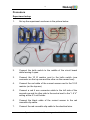
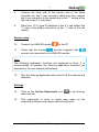
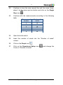
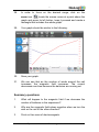
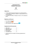
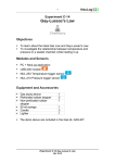
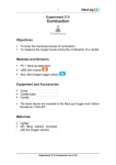
1 Experiment P-16 Basic Electromagnetism Objectives To learn about electromagnets. To build an electromagnet with a nail, a wire and additional electrical elements. To investigate how the number of winds affect the magnetic field of the electromagnet. Modules and Sensors PC + NeuLog application USB-200 module NUL-202 Current logger sensor NUL-214 Magnetic field logger sensor Equipment and Accessories Circuit Board 6V cell holder 1.5 V battery (type D) Knife switch 1 m electrical wire Red 4 mm connector cable Red crocodile clip cable Black crocodile clip and 4 mm connector cable 10Ω mounted resistor Large iron nail 1 1 4 1 1 1 1 1 1 1 The items above are included in the NeuLog Electricity kit, ELE-KIT. Experiment P-16 Basic Electromagnetism Ver 3.3.2 2 Introduction Electromagnets are devices that create a magnetic field through the application of an electric current. An electromagnet consists of a conductive wire wrapped around a piece of metal. A current is introduced from a battery or another voltage source, and flows through the wire. This creates a magnetic field around the wire, magnetizing the metal. It is possible to turn the magnet on and off by completing or interrupting the circuit, this is why electromagnets are so useful. The atoms of certain metals such as iron, nickel and cobalt, each behave like tiny magnets. They normally point in random directions and the magnetic fields tend to cancel each other. The magnetic field produced by the wire wrapped around the core forces some of the atoms to point in one direction. All of the tiny magnetic fields add together, creating a stronger magnetic field. As the current flowing increases, the number of aligned atoms increases and the magnetic field becomes stronger. This happens until all the atoms are aligned and the magnet is saturated (then the magnetic field stays the same). In this activity, you will build an electromagnet and use a sensor to measure the magnetic field strength as a function of the number of wire winds. You will use a current sensor to measure the current during the experiment. Experiment P-16 Basic Electromagnetism Ver 3.3.2 3 Procedure Experiment setup 1. Set up the experiment as shown in the picture below. 2. Connect the knife switch to the middle of the circuit board while leaving it open. 3. Connect the 10 Ω resistor next to the knife switch (one connector on the top row and the other on the second row). 4. Connect the red cable of the current sensor next to the 10 Ω resistor (on the top row). 5. Connect a red 4 mm connector cable to the left side of the second row and its other side to the socket next to the "+ 6 V" writing at the 6 V cell holder. 6. Connect the black cable of the current sensor to the red crocodile clip cable. 7. Connect the red crocodile clip cable to the electrical wire. Experiment P-16 Basic Electromagnetism Ver 3.3.2 4 8. Connect the other side of the electric wire to the black crocodile clip and 4 mm connector cable and then connect the 4 mm connector to the socket next to the "-" writing at the left side of the 6 V cell holder. 9. Place four 1.5 V (type D) batteries in the 6 V cell holder (the "+" side of the battery should be on the "+" side of the cell holder). Sensor setup 10. Connect the USB-200 module to the PC. 11. Check that the current and the magnetic field sensors are connected to the USB-200 module. Note: The following application functions are explained in short. It is recommended to practice the NeuLog application functions (as described in the user manual) beforehand. 12. Run the NeuLog application and check that the sensors are identified. Settings 13. Click on the On-line Experiment icon main icon bar. in the NeuLog 14. This experiment is done in single step mode so the experiment duration and sample rate will not be set. Experiment P-16 Basic Electromagnetism Ver 3.3.2 5 Testing and measurements 15. Rotate the magnetic field sensor to a point where the measured magnetic field is closest to zero (the sensor measures the Earth's magnetic field). 16. Tightly turn the wire 5 times around the nail as shown in the picture below. 17. Hold the nail about 5 mm from the magnetic field sensing part (as seen in the picture). 18. If you see that the magnetic field is negative, remove the wire from the nail and turn it 5 times to the other direction. 19. Click on the Single Step icon 20. Click on the Table icon on the bottom part of the screen. A table will be displayed for data record. 21. Change the "Manual values" column name to "Number of winds" (clicking on the title of the column will allow you to do so). . Experiment P-16 Basic Electromagnetism Ver 3.3.2 6 22. Continue to turn the wire around the nail five more times, place it at the same spot as before and click on the Single Step icon . 23. Continue with the measurements according to the following table. Measurement Number of number winds 1 5 2 10 3 15 4 20 5 25 6 30 24. Open the knife switch. 25. Insert the number of winds into the "Number of winds" column. 26. Click on the Graph icon 27. Click on the Experiment Setup icon X-axis to "Number of winds". . and change the Experiment P-16 Basic Electromagnetism Ver 3.3.2 7 28. In order to focus on the desired range, click on the zoom icon , locate the mouse cursor at a point above the graph and press its left button; keep it pressed and create a rectangle that includes the whole graph. 29. Your graph should be similar to the following: 30. Save your graph. 31. We can see that as the number of winds around the nail increases, the magnetic field increases. The current decreases over time because the batteries are running out. Summary questions 1. What will happen to the magnetic field if we decrease the number of batteries in the experiment? 2. Why are the magnetic field values negative when we turn the wire on the nail to the other direction? 3. Point out two uses of electromagnets. Experiment P-16 Basic Electromagnetism Ver 3.3.2