1
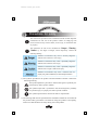
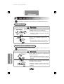
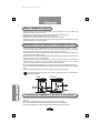
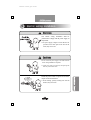
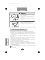
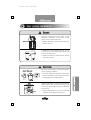
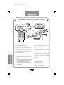
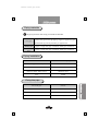
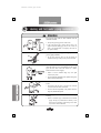
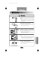
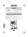
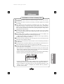
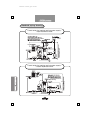
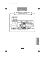
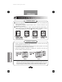
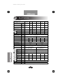
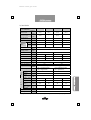
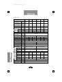
Medium-sized gas boiler
Table of contents
1. Precautions for safety--------------------------------------30
2. Outside drawing of the boiler ----------------------------31
3. Safe and correct installation method --------------------34
4. Electric wiring installation--------------------------------37
5. Gas piping installation-------------------------------------39
6. Heating and hot water piping installation --------------41
7. Exhaust / Intake vent installation ------------------------47
8. Temperature controller installation----------------------52
9. Check points for test operation---------------------------53
10. Electric wiring diagram---------------------------------55
11. Specifications------------------------------------------------56
※ This installation manual is subject to change without notice for quality improvement.
29
Medium-sized gas boiler
1
Precautions for safety
The instructions provided in this installation manual include important
information for safe use of this product. Failure of complying with
those instructions may result in death, severe injury, or tremendous loss
of property.
The instructions for safe use are classified into ‘Danger’, ‘Warning’,
‘Caution’ by the degree of danger, which respectively contains the
following meaning.
Violation of instructions may cause a seriously dangerous
situation such as death or a severe injury
Violation of instructions may cause a potentially dangerous
situation such as death or severe injury.
Violation of instructions may cause a potentially dangerous
situation such as a light or half-serious injury.
Violation of instructions may cause a situation such as a
property loss, product malfunction, or deteriorated performance.
1) The symbols provided in the product and the installation manual contains the
following meaning.
This symbol implies that “precautions” shall be taken against a possibility of a
personal injury under a specific condition.
This symbol implies that a “prohibition” shall be made against a possibility
of a personal injury or a property loss under a specific condition.
This symbol implies that the instructions shall be complied with.
2) The warnings and cautions specified in the installation manual do not include all
the possible safety precautions to be taken for using the product. Consequently,
utmost care shall be taken for safety during use of the product.
30
Medium-sized gas boiler
2
Outside drawing of the boiler
Model no.: KDB-535GTD, GTS, GTG
※ The sizes in the blank “( )” are applied to the model no..
※ A dedicated boiler (GTS, GTG) is not supplied with the hot water inlet and outlet on the rear of
the boiler.
Model no.: KDB-535GPD, GPS
※ The sizes in the blank “( )” are applied to the model no.
※ A dedicated boiler (GPS) is not supplied with the hot water inlet and outlet on the rear of the
boiler.
31
Medium-sized gas boiler
Model no.: KDB-735GTD, GTS, GTG
※ The sizes in the blank “( )” are applied to the model no..
※ A dedicated boiler (GTS, GTG) is not supplied with the hot water inlet and outlet on the rear of
the boiler.
Model no.: KDB-735GPD, GPS
※ The sizes in the blank “( )” are applied to the model no.
※ A dedicated boiler (GPS) is not supplied with the hot water inlet and outlet on the rear of the
boiler.
32
Medium-sized gas boiler
Model no.: KDB-1035GPD, GPS, GPG
1535GPD, GPS, GPG
2035GPD, GPS, GPG
※ The sizes in the blank “( )” are applied to the model no. 1535, and those in the bracket “[ ]” are to the
model no. 2035GPD, GPS, GPG.
※ A dedicated boiler (GPS, GPG) is not supplied with the hot water inlet and outlet on the rear of the
boiler.
33
Medium-sized gas boiler
3
Safe and correct installation method
After completion of installation, be sure to return the user’s (installation) manual to the user.
Before installation
Be sure to check the gas to be used in the
installation place, prior to installation.
Use of the gas, other than the one specified on the
name plate on the front of the boiler, may result
in a fire or explosion.
Be sure to check the power supply gas to be
used in the installation place, prior to
installation.
The power supply, if higher or lower than the one
specified on the front of the boiler, may cause a fire.
Selection of the installation place
After reading the following instructions, install the product in a safe and correct way as
specified in the instructions.
Never install the boiler in a place with
inflammable objects.
Highly inflammable materials, such as volatile
oil or alcohol, may cause a fire during ignition of
the boiler.
Install the boiler in a boiler room free froml
the impact of rain and wind.
Incomplete combustions, resulting from rain and
wind, may eventually lead to a carbon oxide
poisoning.
34
Medium-sized gas boiler
Never install the boiler in a moist or enclosed
place such as a bathroom, a toilet.
Incomplete combustion, caused by oxygen
deficiency, may lead to a carbon oxide poisoning.
Installation in the above place may also cause
earlier product malfunctions.
Never install the product with corrosive gas
such as ammonia, chlorine, sulfur, acids.
Corrosive gas may damage the boiler and cause
incomplete combustion, eventually leading to a
carbon oxide poisoning.
Other considerations
Never install the boiler in the following areas.
Do not install the boiler near the electric equipment.
Do not install the boiler in an uneven or unstable place.
Do not install the boiler in a place with highly combustible materials.
Do not install the boiler in a place inadequate for safe gas piping installation.
Do not install the boiler in a place with special chemical agents
(generating combustible or corrosive gas).
Do not install the boiler in a place where it is difficult to get access to the
stairway or the exit for escaping.
Do not install the boiler in a place which is not well drained.
Do not install the boiler below the shelf with unstable objects.
Do not install the boiler in a place where it is difficult to conduct
maintenance of the boiler after installation.
Do not install the boiler in a place with noise and air pollution.
Do not install the boiler in a place where the wind generated from a vent, a
range, and a hood have an impact on the air intake and exhaust.
Do not install the boiler in a place which is not well-ventilated.
Do not install the boiler in a place with strong wind.
Do not install the boiler in a place where it is difficult to install the
chimney pipe (chimney).
Be sure to install the boiler in a sufficient place for check up and repair of
the boiler.
A space of more than 1m shall be provided in front of the boiler, in order to
perform maintenance and checks.
35
Medium-sized gas boiler
Boiler installation method
Install the boiler on the surface with a structure capable of enduring the load of the boiler (weight). (Refer to the
specifications presented in the user’s manual.)
Install the boiler in a horizontal, upright position so that the boiler does not lean toward one side.
Installation shall be made for the front side of the boiler to face forward.
Install the boiler to be fixed on the floor, in order to prevent vibration during operation.
Sufficient light shall be provided with the boiler room in order to help to observe the boiler equipment by sight
and offer the after-sales service for the equipment.
Precautions for boiler installation in a dedicated boiler room
Be sure to install the boiler in the dedicated boiler room. (The boiler room shall be designed so that the gas
emitted from the boiler does not flow into the living room, and the wall between the boiler room and the
living room shall be made of the fireproof materials, except for the entrance / exit door.)
The dedicated boiler room shall not be equipped with the ventilating fan which causes the negative pressure (the
pressure lower than the atmosphere pressure).
The dedicated boiler room shall not be equipped with the exhaust duct of the gas range (hood) which leads to air
flowing in and out of the living room and the kitchen.
Installation of the boiler shall not be made nearby the place for storage and treatment of the combustible or
inflammable objects. A sufficient space shall be provided for boiler installation as presented in the following
figure, in order to perform the control, combustion, check-ups and repair of the boiler.
The top of the boiler body shall be kept at least 1.2m away from the structures such as the ceiling and the piping.
The boiler body shall be kept at least 450mm away from other structures such as the wall and the piping on the side of the
boiler.
The front of the boiler shall be kept more than 1m away from the structures in front of the wall.
The boiler shall be kept away from the nearby combustible objects, as illustrated in
the following figure.
Precautions for installation of the boiler in the outdoors
Appropriate facilities such as the casing shall be equipped with the boiler to prevent the rain from permeating into
the boiler.
The waterproof treatment shall be applied to the exposed insulation materials or lagging.
Proper measures shall be taken to protect the water pipe outside the boiler from getting frozen.
Proper measures shall be taken for boiler combustion to be protected against snow, rain and wind.
36
Medium-sized gas boiler
4
Electric wiring installation
The electric wiring installation shall be
performed to comply with the power supply of
the product.
The power supply, if higher or lower than the one
specified on the name plate on the front of the
boiler, may cause a fire.
Do not connect the power supply to the boiler until the
electric wiring installation is completed.
With the power supply on, the electricity flowing through the
boiler may cause an electric shock.
Install the power outlet in a place free from the
impact of rain and moisture.
Electric leakage, possibly resulting from rain and
moisture, may cause a fire.
37
Medium-sized gas boiler
Never make a ground connection to the lightning
rods and the gas pipe.
Ground connection to the lightning rod may result in a boiler
malfunction.
Ground connection to the gas pipe may result in an explosive
accident.
Be sure to use the magnet switch for connection of the
circulation pump with more than 1.5kW.
The boiler may malfunction, without the magnet switch.
Correct electric wiring installation
Install the electric wiring as presented in the electric wiring drawing in the installation manual.
Install the dedicated power outlet for the boiler, with a length of less than the effective length of
the power cord. Installation shall be made for the power outlet not to get in contact with the drain
valve of the boiler.
Use the power outlet with a cover attached, and install the outlet at more than 300m above
ground level.
If the power outlet is not provided with a cover, install the outlet in a place free from the impact
of rain or moisture, or in the waterproof box or the indoor distribution box.
Never install a switch onto the power cord, nor use the power outlet with a switch attached. (The
boiler does not operate, when the switch is set at off.)
A ground connection shall be installed, if not, on the side of the power outlet.
The wires of the room temperature controller shall be connected through the insulation pipe with
a thickness of more than 4mm. The insulation pipe shall be installed and concealed with an
upper gradient toward the indoors.
The wires of the circulation pump, connected to the controller, shall not be
short-circuited.
38
Medium-sized gas boiler
5
Gas piping installation
Be sure to perform the gas leak test after gas pipe
installation, replacement of the burner, or the
supply pressure or head pressure test.
Retention of the leaked gas, combined with static electricity or
spark, may cause a fire
In preparaion for the unexpected gas leak, be sure
to install the gas leak alarm device and the gas
breaker in the boiler room.
Retention of the leaked gas, combined with static electricity
or spark, may cause a fire
Be sure to check the gas to be used for the product
prior to gas piping installation.
Use of the gas, other than the one specified on the name plate
on the front of the boiler, may cause incomplete combustion,
eventually leading to a fire or explosive ignition.
Install the gas holder, if used, in the well-ventilated
outdoor without above ground high voltage power
line. The gas holder shall be fixed not to fall down
on the ground.
If the gas holder falls down or gets in contact with the high
voltage power line, an explosive accident may occur.
39
Medium-sized gas boiler
The gas piping installation shall be performed by the gas
company and the gas piping installation company.
1 Refer to the “Specifications” presented in this installation
manual, with regard to the connection size.
2 Use the metal pipe or the metal flexible pipe which
passed a gas appliance test for gas piping. When LP gas
is used, never install the fuse cock, and be sure to install
the gas middle valve. (Installation of the fuse cock may
cause a boiler malfunction.)
3 The following shall be kept in mind, when using LP gas.
The domestic low pressure regulator, appropriate for the
indicated gas consumption, shall be used as the LP gas
regulator.
2 or more vessels with a weight of 50kg shall be installed
to be used for the LP gas vessel. (Connect the twin valve
to simultaneously supply the gas from 2 vessels.)
※ The vessels with a small capacity may result in gas loss
for lack of vaporization volume, which may cause a
boiler malfunction.
40
4 Be sure to connect the gas pipe directly to the main
pipe. Never connect the gas pipe in common with
other gas appliances.
5 A separable union connection or a nut connection
shall be made on the connection points.
6 The gas pipe shall be installed with its surface
exposed to the outside. However, the copper pipe, the
stainless steel pipe, or other pipes made of heat- and
corrosion-resistant materials without connection
joints (except for welding joints) may be buried for
installation.
7 Be sure to install the gas leak alarm device and the
gas breaker in the boiler room.
LP gas: lower than the boiler
(300mm above the ground level)
LNG
: higher than the boiler
Medium-sized gas boiler
Piping materials
The piping materials shall comply with the Korea Standard.
Carbon steel pipe for fuel gas piping, Copper or copper alloy pipe,
Gas pipe
Metal flexible pipe which passed the gas appliance test
Heating pipe
Copper or copper alloy pipe+Insulation, XLPE pipe+Insulation
Hot water
pipe
Copper or copper alloy pipe+Insulation, XLPE pipe+Insulation
Piping installation
Items
Distance from the gas pipe
Flue pipe & chimney
300mm or more
Electric switch, Power outlet
300mm or more
Electricity meter, Safety cutout
600mm or more
Wire
150mm
Fixing the pipe
Size of the pipe
Interval
13mm or less
To fix every 1m
13mm~33mm
To fix every 2m
33mm or more
To every 3m
41
Medium-sized gas boiler
6
Heating and hot water piping installation
The exposed pipes shall be heat insulated with the
insulation material.
The exposes pipes may get frozen in the winter.
If the water supply pipe is frozen, the hot water is not
supplied. When the heating pipe has run out of water, the
water is not supplemented. Consequently, the boiler can
not operate normally.
Fix the parts of the boiler pipes with appropriate tools,
prior to piping installation.
Do not exert excessive force on the pipe during the
installation, Damages on the parts may cause a water leak.
Be sure to use the insulation flange on the heating
inlet and outlet in case of installation of the copper
pipe (the hot water inlet and outlet for a boiler
dedicated for hot water supply).
Failure to use the insulation flange may cause rapid
corrosion (rusty water).
We do not take the responsibility of the problems arising from
failure to use the insulation flange.
Do not use water, other than the tap water, for the
boiler.
Salt content in the sea water or spa water may accelerate
corrosion and shorten the life of the boiler.
We do not take the responsibility of the problems caused by
using water, other than the tap water.
Install the pipes as illustrated in the standard pipe
drawing.
Failure to install the pipe as illustrated in the standard
piping drawing may deteriorate the efficiency of the
boiler and the circulation of the heating water, which
may result in a boiler malfunction.
42
Medium-sized gas boiler
Precautions for piping installation
Considerations in common
A separable union connection or a nut connection shall be performed on the connection points.
The piping materials shall comply with the Korea Standard.
Do not use the metals with different electric potentials to install the piping in the
dedicated boiler for hot water supply, (For example, do not install the copper pipe in the
iron boiler.) which may cause galvanic corrosion, eventually generating rusty water.
Do not use the rubber hose for the faucet, when installing the piping.
Be sure to remove foreign objects inside the pipe prior to the piping installation.
Install the piping correctly for the water supply, the hot water supply, the heating, and
the drain.
The heating pipe shall be equipped with the heating strainer.
If the water supply pressure exceeds the allowable working pressure specified on the
name plate, be sure to install the depressurizing valve.
Proper measures shall be taken against a water leak through a water leak test for the
entire piping after completion of installation.
The entire pipelines, except for the gas pipe, shall be provided with heat insulation to
protect against getting frost, after completion of installation. (Especially, care shall
be taken for the water supply and the hot water pipes.)
Be sure to install the pressure release pipe for installation of the boiler. If it is
impossible to install the pressure release pipe, the safety valve, operating below the
maximum allowable working pressure of the boiler, shall be installed.
(The maximum allowable working pressure of the boiler is presented in the
“Specifications”.)
Never install the valve and the check valve in the pipeline where the pressure release
pipe or the safety valve is installed.
Select the boiler expansion tank, if necessary, with a capacity suitable for the boiler
in use.
Do not use the water inlet for the purpose of the drain, and vice versa.
If the water is supplied to the boiler from the rooftop water tank, be sure to install the
water supply pipe in the auxiliary tank, separate from the rooftop water tank, for
water supply to the boiler.
Install the pipes as illustrated in the standard pipe drawing.
43
Medium-sized gas boiler
Precautions for the piping installation for the combi boiler for
heating and hot water supply / the dedicated boiler for heating
Model no. : KDB-535, 735 GTD, GTS
KDB-535, 735, 1035, 1535, 2035 GPD, GPS
Open piping system
- Be sure to comply with the instructions presented in the “Considerations in common”.
- Be sure to install the air vent valve in the distributor.
- The return water distributor shall be installed below the heating inlet on the boiler.
- The pressure release pipe shall be installed to exceed 25A.
- Never supply the water with a pressure higher than the maximum allowable working
pressure of the boiler specified on the name plate, nor connect the water pipe directly
for the piping.
- The reverse flow of the heating water into the expansion tank, while operating or
stopping the circulation pump, results from too much air in the pipe. (Open the valve in
the distributor one by one and remove the air from the pipe, while operating the
circulation pump.)
- The expansion tank shall be installed at least 1.5m above the heat dissipation surface in
case of the upward type, and at least 1.5m above the top of the boiler in case of the
downward type.
- The piping installation shall be performed not to mix the heating water and the hot
water.
Closed piping system
- Be sure to comply with the instructions presented in the “Considerations in common”.
- Be sure to install the strainer, the depressurizing valve, the check valve, and the closed
expansion tank, in order to directly connect the boiler to the water pipe.
- Be sure to install the depressurizing valve and the check valve in the water supply pipe.
- Install the air vent on top of the heat dissipation surface to facilitate air vent.
- Be sure to install the strainer in the water supply pipe, in order to prevent metal and
foreign objects from flowing into the water supply pipe.
- Be sure to install the safety valve.
- Be sure to install the closed expansion tank with an appropriate capacity.
44
Medium-sized gas boiler
STRAINER
Composition
1. Body
2. Cap
3. Cap gasket
4. Strainer screen
Features: The device is to remove foreign objects in the boiler and the heating pipeline.
1. Prevention of corrosion in the pipe: The portion of accumulated foreign objects inside the pipe
gets corroded first. Accordingly, the foreign objects shall be strained to prevent corrosion.
2. Extension of the boiler life: The accumulated foreign objects obstruct heat transfer, and the
accumulated portion is overheated, which shortens the life of the boiler. Consequently, the
foreign objects shall be strained to extend the boiler life.
3. Protection of main equipment: The heating circulation pump, the valve, and other equipment
are protected from being damaged by foreign objects.
Installation method
1. Install the strainer in the direction of the heating water flow, as indicated in the body of the
heating strainer.
2. You may install the strainer in a horizontal or vertical direction, as desired.
3. Install the valves on each end of the heating strainer, in order to prevent the heating water
from draining during cleaning of the strainer.
4. The pocket shall be installed to face the ground surface, and a sufficient space shall be
provided for cleaning the strainer.
The method of cleaning (Removal of foreign objects)
1. Close the valves on each side of the strainer, to
completely shut off the heating water.
2. Open the cap to remove the foreign objects on the
strainer screen.(! Caution: Care shall be taken against
a burn, possibly caused by the heating water.)
3. After cleaning, check if there is a leak of the heating
water. Then, open the valve to use the strainer.
4. The heating strainer shall be cleaned periodically. At
the beginning of use, foreign objects usually remain
in the pipe, which shall be cleaned out.
45
Medium-sized gas boiler
Precautions for the piping installation for the
dedicated boiler for hot water supply
Model no.: KDB-535, 735 GTG
KDB-1035, 1535, 2035 GPG
Open piping system
- Be sure to comply with the instructions presented in the “Considerations in common”.
- Never supply the water with a pressure higher than the maximum allowable working
pressure of the boiler specified on the name plate, nor connect the water pipe directly
for the piping.
- Be sure to use the coated piping material and the stainless piping material for the
dedicated boiler for hot water supply.
- The pressure release pipe shall be installed to exceed 25A.
- The expansion tank shall be installed at least 1.5m above the maximum height of the
hot water pipe in case of the upward type, and at least 1.5m above the top of the boiler
in case of the downward type.
- When installing the hot water storage tank, connect the hot water outlet to lower part (inlet)
of the hot water tank, and the hot water inlet to the upper part (outlet) of the hot water tank.
- Use the connection wire to the circulation pump of the boiler to install the hot water
storage tank separately.
- If the water pressure is too low, attach an additional pump to the hot water outlet.
- When attaching an additional pump, be sure to install the pressure switch (S/W) and the
check valve. (Do not connect them to the wire of the circulation pump of the boiler.)
Closed piping system
- “Be sure to comply with the instructions presented in the “Considerations in common”.
- Be sure to install the strainer, the depressurizing valve, the check valve, the safety valve,
and the closed expansion tank, in order to directly connect the boiler to the water pipe.
- Be sure to use the coated piping material and the stainless piping material for the dedicated
boiler for hot water supply.
- Be sure to install the depressurizing valve and the check valve in the water supply pipe.
- Install the air vent on top of the hot water supply pipe to facilitate air vent.
- Be sure to install the safety valve.
- Be sure to install the closed expansion tank with an appropriate capacity.
- When installing the hot water storage tank, connect the hot water outlet to lower part (inlet)
of the hot water tank, and the hot water inlet to the upper part (outlet) of the hot water tank.
- Use the connection wire to the circulation pump of the boiler, in order to install the hot
water storage tank separately.
- If the water pressure is too low, attach an additional pump to the hot water outlet.
- When attaching an additional pump, be sure to install the pressure switch (S/W) and the
check valve. (Do not connect them to the wire of the circulation pump of the boiler.)
46
Medium-sized gas boiler
7
Exhaust / Intake vent installation
Installation of the exhaust and intake chimney
pipe (chimney) shall be performed in a specified
method.
Incorrect installation of the exhaust and intake
chimney pipe (chimney) may lead to an exhaust
gas poisoning.
The connection points of the exhaust and intake
pipes shall be free from any leakage.
The exhaust gas, if flowing into the indoors, may
cause carbon oxide poisoning.
The air intake or the exhaust vent shall be
installed in the outdoors or a well-ventilated
place where the exhaust gas emitted from the
vent does not flow into the indoors.
The exhaust gas, if flowing into the indoors, may
cause carbon oxide poisoning.
Be sure to install the air intake and the exhaust
vent.
Failure of ventilation may lead to incomplete
combustion due to oxygen deficiency, which may
eventually result in carbon oxide poisoning.
The boiler of the forced exhaust type (FE) can
not employ the multiple exhaust ducts.
The reverse flow of the exhaust gas may cause
carbon oxide poisoning.
47
Medium-sized gas boiler
The horizontal section of the chimney pipe shall
be installed to be inclined downward at an angle
of 5°, to prevent the condensed water or rain
from flowing in reverse into the boiler.
Flow of the condensed water or rain into the
boiler may deteriorate the performance of the
boiler and shorten the life of the boiler.
r
Installation of the chimney pipe for the forced exhaust type (FE) boiler
■ The exhaust duct type of the forced exhaust type (FE) boiler: the single exhaust type, the
chamber type, the shared exhaust type
■ The total length of the exhaust duct shall be kept to 10m or less, and the curved parts to 3
segments or less. (except for the curve on the edge point of the exhaust duct)
■ The connection size of the exhaust duct shall comply with the specifications. (Refer to the
specifications.)
■ Care shall be taken to prevent the middle part of the exhaust duct from getting narrower. The
exhaust duct shall be installed to keep the radius of the curved part at maximum as possible.
■ The exhaust duct shall be heat insulated with the non-flammable insulation material.
48
Medium-sized gas boiler
Installation of the chimney pipe
■ The exhaust duct shall be made of the stainless steel (pipe) or the heat- and corrosionresistant metal.
■ The exhaust duct shall be connected, if necessary, to the boiler tightly not to be pulled
out or shaken.
■ If the exhaust duct passes through the combustible wall or the ceiling made of
combustible material, the exhaust duct shall be heat insulated with a non-flammable
material with a thickness of more than 20mm, and kept at least 50mm away from the
wall or the ceiling. In addition, the exhaust duct, if passing through the ceiling, shall be
equipped with the inspection hole.
■ The exhaust duct shall be installed as a single unit, if possible. Never use the exhaust
duct in common with the heaters of the natural exhaust type or those using other fuel
(briquette, petroleum).
■ The air intake shall be provided in a well-ventilated place such as the outdoors, into
which the exhaust gas emitted from the exhaust duct does not flow.
(※ Make sure that failure of air intake and ventilation causes oxygen deficiency,
eventually leading to incomplete combustion.)
■ Bore holes in the wall to install the vent on the upper side of the wall and the air intake
on the lower side, to facilitate ventilation.
■ The effective cross-sectional area of the air intake or the vent shall be larger than that of
the exhaust duct.
■ The bird protection net shall be installed on top of the exhaust duct so that birds, mice or
objects with a diameter of more 16mm can not go into the exhaust duct.
■ A space of more than 300mm shall be provided between the top of the exhaust duct and
the outer wall surface, if non-flammable.
If the exhaust duct is to be installed and concealed into the ceiling, the connection points
shall be securely connected to prevent exhaust gas leakage. Then, wind a non-flammable
material, other than the metal, around the connection points.
Finish the connection points using the heat resistant silicon (except for the plaster bandage).
Install the inspection hole to check and repair the exhaust pipe in a dark side.
In order to extend the exhaust pipe, install one hanger at least every 900mm and tighten the
installed hangers securely. (in case of the pipe extension with a length of more than 1m)
Incorrect installation of the exhaust pipe may cause deteriorated performance of the
product as well as a disaster. Consequently, the installation shall be performed in
accordance with this manual.
49
Medium-sized gas boiler
Standard piping drawing
Combi boiler for heating and hot water supply“Open expansion tank”
Combi boiler for heating and hot water supply“Closed expansion tank”
50
Medium-sized gas boiler
Dedicated boiler for hot water supply
“Closed expansion tank”
51
Medium-sized gas boiler
8
Installation of the temperature controller
Installation place
■ Install the temperature controller on the wall of the room to be provided with
frequent indoor heating.
The temperature controller shall be installed 1.2m to 1.5m above the floor, with
sufficient air circulation.
■ Do not install the controller in a place nearby the frequently opened door, or
where cold wind blows, or under direct sunlight, or easily accessible by children.
(The example of the installation place, ● : Temperature controller
Installation method
1. Connect 2 temperature controller wires from the boiler to 2 wires on the rear side
of the temperature controller securely.
2. Fix the bracket of the temperature controller onto the desired position on the wall,
or into the holes of the wall outlet using a bolt.
3. Install the temperature controller by hanging the connection wire onto the
bracket carefully in the desired direction.
Note : Do not exert excessive force while connecting the wire, and secure the bolt tightly. Pushing the
temperature controller upward will separate the temperature controller and the bracket. If the cover of
the wire peels off or the terminal connection is inferior, the temperature controller may not function
normally. Consequently, care shall be taken for the insulation treatment of the temperature controller.
52
Medium-sized gas boiler
9
Check points for test operation
1) Check if the boiler is installed correctly.
① Check if the floor surface is made of strong and flat non-flammable materials
such as concrete and if the surrounding area is also made of non-flammable
materials.
② Check the air intake and vent in the boiler room.
③ Check if the boiler room is provided with a drain, and if the boiler is equipped
with the drain valve.
④ Check if the boiler and the pipeline are heat insulated to prevent frost damage.
⑤ Check if the flue pipe is correctly installed.
⑥ Check if rain does not permeate through the penetration portion of the exhaust
pipe.
⑦ Check if the boiler is evenly installed.
⑧ Check if there is water leakage near the piping connection joint.
⑨ Check if there is any leakage near the gas pipe connection joint.
⑩ Check if the boiler room is equipped with the gas leak alarm device and the gas
breaker.
- The location of installation of the gas leak alarm device
LNG : 300mm from the ceiling
LPG : 300mm from the floor
⑪ Check if the fuel is the same as the gas specified on the name plate of the boiler.
⑫ Check if the pressure release pipe or the safety valve are installed in the boiler.
⑬ Check if the ground wire is connected. (If the ground connection is made on the
fuel pipe or the lightning rod, change the position.)
53
Medium-sized gas boiler
Test operation
1) Open the water supply valve to supplement water in the boiler.
The water supply pressure shall be kept to less than the allowable working pressure,
specified on the name plate of the boiler.
- Upon completion of water supplement, the makeup water lamp on the controller
goes out.
2) Connect the boiler to the power supply.
Do not touch the power cord with wet hands.
3) Push the power switch of the boiler controller to on.
4) Open the valve on the fuel line.
5) Set the room temperature controller S/W at the operation mode.
6) After ignition of the boiler, check the combustion mode and the heating
circulation mode.
① Set the temperature on the temperature controller → Set the room temperature
controller button (High speed, Temperature, Time) at ON → Operation of the
burner fan → Check the gas pressure → Check the wind pressure →
Operation of the ignition transformer → Open the 1st and 2nd gas valve →
Ignition → Flame detection → Combustion → ON/OFF in accordance with
the temperature setting (operation of the circulation pump)
② Check if the boiler stops operation and the circulation pump is operating, by
adjusting the temperature controller from the boiler controller.
7) Press the “Hot water” button on the room temperature controller (DR-1), in
order to check if the circulation pump stops operation and hot water is supplied.
8) Press the “Outside” button on the room temperature controller to check if the
boiler stops operation.
54
Medium-sized gas boiler
10
Electric Wiring Diagram
55
Medium-sized gas boiler
11
Specifications
1) Stainless boiler
Classification
Heating output
Hot water output
Hot water supply
capacity (△ 40℃)
Model no.
535GTD
535GTS
535GTG
735GTD
735GTS
735GTG
kcal/h
(kW)
kcal/h
(kW)
50,000
(58.1)
50,000
(58.1)
50,000
(58.1)
-
70,000
(81.3)
-
-
50,000
(58.1)
70,000
(81.3)
70,000
(81.3)
-
70,000
(81.3)
ℓ/min
21
-
21
29
Purpose
Combi
%
Efficieny LNG
(Total) LPG
%
Fuel
Maximim allowable kgf/cm2
working pressure
(MPa)
Heat transfer area
m2
Heating area
m2
Volume of pipe water
ℓ
Weight
kg
Power supply
Burner Model no.
Power consumption
W
Gas pressure
-
29
Heating
only
92.8
92.8
Hot water
only
92.8
92.8
2.78
140
68
102
68
102
3.5 (0.343)
100
40
100
1.96
100
46
93
140
46
60
93
110
1φ, 220V, 50Hz
KPG-50A
143
KPG-70A
208
LN gas : 200+50
-100, LP gas : 280±50
mmH2O
LNG : 61,000kcal/h(70.9kW)
LPG : 5.1kg/h(70.9kW)
Fuel consumption
Width
Depth +
size
Burner
Height
Heating inlet
·Outlet
Drain
Piping Discharge
size outlet
Hot water
inout·Outlet
Gas inlet
Chimney size
Exhaust gas
92.3
92.3
Heating Hot water Combi
only
only
92.2
92.2
92.6
92.2
92.2
92.6
City gas (13A), LP gas
LNG : 84,000kcal/h(97.6kW)
LPG : 7kg/h(97.6kW)
Ng mm
547
547
mm
848
837
mm
1,032
1,240
A
40
40
-
40
40
-
A
40
40
40
40
40
40
A
40
40
40
40
40
40
A
20
-
40
20
-
40
A
φ
℃
15
148
250 or less
※ The specifications presented in this manual is subject to change without notice for quality improvement.
56
Medium-sized gas boiler
2) Steel boiler
Classification
Heating output
Hot water output
Hot water supply
capacity (△ 40℃)
Purpose
Efficiency
(Total)
Model
535GPD
535GPS
735GPD
735GPS
kcal/h
(kW)
kcal/h
(kW)
50,000
(58.1)
50,000
(58.1)
50,000
(58.1)
70,000
(81.3)
-
70,000
(81.3)
70,000
(81.3)
ℓ/min
21
-
29
-
Combi
Heating only
Combi
Heating only
-
LNG
%
92.6
92.7
92.8
92.8
LPG
%
92.6
92.7
92.8
92.8
Fuel
Maximum allowable
working pressure
Heat transfer area
City gas (13A), LP gas
kgf/cm2
(MPa)
m2
3.5 (0.343)
2.34
3.10
Heating area
m2
Volume of pipe water
ℓ
56
63
72
85
kg
151
146
180
173
Weight
Power supply
Burner Model no.
Power consumption
Gas pressure
100
140
140
1φ, 220V, 50Hz
KPG-50A
143
W
KPG-70A
208
LP gas: 280±50, LNG : 200+50
-100
mmH2O
LNG : 61,000kcal/h(70.9kW),
LPG : 5.1kg/h(70.9kW)
Fuel consumption
Width
Prod
uct Depth +
size Burner
Height
Heating inlet
·outlet
Pipi Drain
ng
Discharge
outlet
size Hot water
inlet·outlet
Gas inlet
Flue size
Exhaust gas
100
LNG : 84,000kcal/h(97.6kW),
LPG : 7kg/h(97.6kW)
mm
547
547
mm
850
838
mm
1,148
1,410
A
40
40
40
40
A
40
40
40
40
A
40
40
40
40
A
20
-
20
-
15
148
250 or less
A
φ
℃
※ The specifications presented in this manual is subject to change without notice for quality improvement.
57
Medium-sized gas boiler
3) Steel boiler
Classifications
Heating Output
Hot water Output
Capacity of hot water
supply (△ 40℃)
Model
1035GPD
1035GPS
1035GPG
1535GPD
1535GPS
1535GPG
kcal/h
(kW)
kcal/h
(kW)
100,000
(116.2)
100,000
(116.2)
-
150,000
(174.4)
150,000
(174.4)
-
100,000
(116.2)
-
100,000
(116.2)
130,000
(151.1)
-
150,000
(174.4)
ℓ/min
42
-
42
54
-
63
Combi
Heating
only
91.2
91.2
Heating
only
91.5
91.5
Hot water
only
91.5
91.5
4.77
992
188
370
188
370
Purpose
Efficiency LNG
(Total)
LPG
Fuel
Maximum allowable
working pressure
Heat transfer area
Heating area
Volume of pipe water
Weight
Power supply
Burner Model no.
Power consumption
Gas pressure
%
%
kgf/cm2
(MPa)
m2
m2
ℓ
kg
3.5 (0.343)
662
135
267
3.32
662
148
248
992
148
173
248
390
1φ, 220V, 50Hz
KPG-100A
224
W
KPG-150A
232
LP gas: 280±50, LNG : 200+50
-100
mmH2O
mm
LNG : 124,000kcal/h(144.1kW)
LPG : 10.3kg/h(144.1kW)
687
LNG : 178,000kcal/h(206.9kW)
LPG : 14.8kg/h(206.9kW)
796
mm
994
1,094
mm
1,403
1,411
Fuel consumption
Width
Product Depth+
Size Burner
Height
Heating inlet
·outlet
Drain
Piping Discharge
size outlet
Hot water
inlet·outlet
Gas inlet
Flue size
Exhaust gas
91.2
91.2
Hot water Combi
only
91.2
91.5
91.2
91.5
Citygas (13A), LP gas
A
65
65
-
80
80
-
A
65
65
65
80
80
80
A
65
65
65
80
80
80
A
20
-
65
20
-
80
A
φ
℃
20
25
200
250 or less
※ The specifications presented in this manual is subject to change without notice for quality improvement.
58
Medium-sized gas boiler
4) Iron boiler
Classification
Model
2035GPD
2035GPS
2035GPG
HeatingOutput
kcal/h
(kW)
200,000
(232.5)
200,000
(232.5)
-
Hot waterOutput
kcal/h
(kW)
130,000
(151.1)
-
200,000
(232.5)
ℓ/min
63
-
83
Combi
Heating only
Hot water only
%
92.0
92.0
92.0
%
92.0
92.0
92.0
Hot water supply
capacity (△ 40℃)
Purpose
Effici LNG
ency
(Total) LPG
City gas (13A), LP Gas
Maximum allowable
working pressure
Heat transfer area
Heating area
kgf/cm2
(MPa)
m2
3.5 (0.343)
6.46
m2
1323
1323
-
Volume of pipe water
ℓ
237
255
255
Weight
kg
475
450
450
Power supply
Burner Model no.
Power consumption
Gas pressure
1φ, 220V, 50Hz
W
KPG-200A
366
mmH2O
LP gas: 280±50, LNG : 200+50
-100
LNG : 24Nm3/h, 252,000kcal/h(293.0kW), LPG : 21kg/h
Fuel consumption
Width
Product Depth +
size
Burner
Height
Hot water
inlet·outlet
Drain
Piping Discharge
size outlet
Hot water
inlet·outlet
Gas inlet
mm
796
mm
1,165
mm
1,716
A
32
Flue size
Exhaust gas
φ
℃
200
250 or less
A
80
80
-
A
80
80
80
A
80
80
80
A
20
-
80
※ The specifications presented in this manual is subject to change without notice for quality improvement.
59
Medium-sized gas boiler
MEMO
60
Medium-sized gas boiler
MEMO
61
Medium-sized gas boiler
MEMO
62
Medium-sized gas boiler
MEMO
63
Medium-sized gas boiler
MEMO
64