1
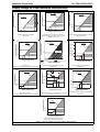
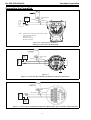
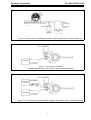
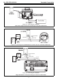
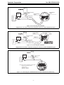
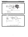
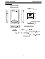
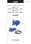
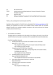
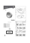
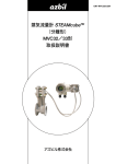
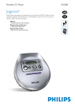
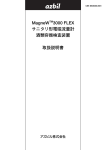
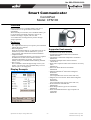
No. SS2-CFN100-0100
Smart Communicator
CommPad
Model: CFN100
Overview
Smart Communicator CommPad Model CFN100 is a
communicator to set up and monitor smart field
instruments.
With a friendly user interface, the CommPad enables you
to set and check instrument parameters such as tag
numbers and ranges, outputs, and view data.
A saved data can be managed with your PC through
simple operations.
Features
• Easy to handle
The simple menus allow you to operate your CommPad
without the user's manual.
• Data management
Since the instrument data set or collected on site can be
loaded into your PC without modification, you can
easily manage and maintain the instrument database.
• Comparison table
Using a list comparison function, you can see at a glance
the differences in data between before and after
parameter adjustments or settings. You can work
steadily with your CommPad without making mistakes.
• Easy to carry
The CommPad is small and light enough to fit in your
pocket, you can bring your CommPad safely even in a
narrow space or at a high place.
Supported Instruments
• AT9000 Advanced Transmitter
• ST3000 Series 900 Smart Transmitter
• ST3000 Smart Multivariable Flow Transmitter
Model JTD720A
• ThermoPLUS Advanced Temperature Transmitter
Model ATT
• SVP3000 Alphaplus Smart Valve Positioner
Model AVP
• Smart Valve eXplorer Smart Valve Positioner for rotary
Valve
Model SVX
• PTG series Smart Pressure Transmitter
Model PTG
• MagneW3000 PLUS+ Smart Electromagnetic
Flowmeter
Model MGG
(Not compatible with versions earlier than 6.0.)
• MagneW Two-wire PLUS+ Smart Electromagnetic
Flowmeter
Model MTG
(Not compatible with versions earlier than 5.0.)
• Steam Flowmeter STEAMcube
Model MVC
• Smart Displacement type Level Transmitter
Model SLX
• Smart ALTJ3000 Immersion Type Liquid Level
Transmitter
Model JTL
Display Example
Specifications are subject to change without notice.
- 1-
1st Edition: Issued in Apr. 2006
5th Edition: Issued in Apr. 2008
No. SS2-CFN100-0100
Yamatake Corporation
Specifications
Model number structure
Ambient temperature: 0 to 40°C
Ambient humidity: 30 to 80% RH (provided there is no
condensation)
Power source:
Operation - a lithium-ion rechargeable battery
Operation period - approx. 27 hours *1
Memory backup - a nickel hydride battery (built-in)
Environmental performances:
Dust/Water-splash proof - JIS splash-proof model (IP54
equivalent) *2
Drop durability: 1.0 m *3
Weight:
Communication interface card - approx. 10 g
Communication cable - approx. 30 g
Pocket PC (CASIO DT-10) - approx. 290 g (including a
rechargeable battery)
Product configuration:
Pocket PC (CASIO DT-10), communication interface
card, communication cable, software (CD-R), and AC
Adapter
Smart Field Communicator CommPad Model CFN100
Basic model number
CFN100
-
Communication interface Communication card
1 S
1
Communication method SFN analog
Comunication Cable
*1 Battery life varies depending on the environment in which
you use your CommPad.
*2 When all covers are closed.
*3 When the card is not installed.
-2-
- X
S
Alligator clips
1
Easy hooks
2
Alligator clips + Easy hooks
3
PDA model/ Display
DT-10 (Japanese v ersion)
1
language
IT-10 (English v ersion)
2
Options
None
X
Cradle
C
Screen protection sheet (5 sheets)
S
Yamatake Corporation
No. SS2-CFN100-0100
Supply voltage vs. Load resistance characteristics
1560
R= E - 12.5
0.0219
Operable range
R=
Load resistance R(Ω)
Operative limit
605
Operable range
250
245
0
0
12.5 17.9
42 45
Supply voltage E (V DC)
AT9000 Advanced Transmitter
Model GTX
24
0
Load resistance R(Ω)
Operable range
250
11.5 17.5
24
Supply voltage E (V DC)
45
1243
R=
E-11.5
0.0218
Operable range
250
42
17 23.4 24
Supply voltage E (V DC)
ST3000 Smart Multivariable Flow Transmitter Model JTD720A
850
521
Operable range
280
250
45
ST3000 Series 900 Smart Transmitter,
SVP3000 Alphaplus Smart Valve Positioner
Model AVP 301/201
R= E - 11.5
0.024
Load resistance R(Ω)
10.8 16.3
R= E - 17.9
0.0218
Supply voltage E (V DC)
1271
0
1243
E - 10.8
0.0218
Load resistance R(Ω)
Load resistance R(Ω)
1345
Load resistance R(Ω)
1482
0
16.9
11.5
Communication and
No communication type
E - 16.7
R= 0.0229
1000
750
500
320
Operable range
250
245
30
24
16.7
22.28 22.4
Supply voltage E (V DC)
No communication type
45
Supply voltage E (V DC)
E - 8.5
R=
0.025
620
Operable range
300
250
Load resistance R(Ω)
1164
1460
Load resistance R(Ω)
PTG series Smart Pressure Transmitter
Model PTG
8.5
16
24
Supply voltage E (V DC)
R= E-15.6
0.0218
2 30<E<42
R= E-14.25
0.02383
661
2
1
385
Operable range
250
15.6 21.05 24 30
Supply voltage E (V DC)
45
MagneW3000 PLUS+
Smart Electromagnetic Flowmeter Model MGG
1467
1 21.05<E<30
0
0
Steam Flowmeter STEAMcube
Model MVC
42
MagneW Two-wire PLUS+ Smart Electromagnetic
Flowmeter Model MTG
Load resistance R( )
ThermoPLUS
Advanced Temperature Transmitter Model ATT
R= E-13
0.0218
500
Operable
fi
´ range
\ ˝ ˝
250
0
13.0
24
18.5
Supply voltage E (V DC)
Smart Displacement type Level Transmitter
Model SLX
Load resistance R(Ω)
1510
R= E - 12.1
0.0218
Operable range
545
250
0
12.1 17.6 24
Supply voltage E (V DC)
45
Smart ALTJ3000 Immersion Type
Liquid Level Transmitter Model JTL
Figure 1 Supply voltage vs. Load resistance characteristics
-3-
45
No. SS2-CFN100-0100
Yamatake Corporation
Connecting the CommPad
24V DC
power
supply
+
Receiver
-
Red lead
Communications
cable
Black lead
+
250 Ω
Note:
A lways connect CommPad's communications cable
to the loop wiring asfollows:
Always connect
Red lead: S+ terminal
Back lead: S- terminal
Figure 2-1 Connecting the CommPad
(Wiring for connection with Model GTX)
DC24V
power
supply
+
Receiver
-
Red lead
Communication
cable
Black lead
CH
K -/S
- @ @ @S+
+
DISP FLOW
250 W
¢UP ZERO DOWN ⁄
E
CH
K+
/M -
M+
Figure 2-1
Figure 2-2 Connecting the CommPad (ST3000 Series 900 Smart Transmitter)
Receiver
Communication
cable
250 Ω
+
Black lead
Red lead
-
+
24V DC
power
supply
Figure 2-3 Connecting the CommPad (ST3000 Smart Multivariable Flow Transmitter Model JTD720A)
-4-
Yamatake Corporation
No. SS2-CFN100-0100
Input wiring on
the sensor side
DC24V
power supply
Output wiring
Load resistance
(250 W)
Receiver (recorder,
etc.)
Figure 2-4 Connecting the CommPad (ThermoPLUS Advanced Temperature Transmitter Model ATT)
Controller
Figure 2-5 Connecting the CommPad
(SVP3000 Alphaplus Smart Valve Positioner Model AVP300/302/200/202)
Monitoring
system
250 W
DC24V
resistance power
supply
Controller
Figure 2-6 Connecting the CommPad (SVP3000 Alphaplus Smart Valve Positioner Model AVP301/201)
-5-
No. SS2-CFN100-0100
Yamatake Corporation
Controller
Figure 2-7 Connecting the CommPad
(Smart Valve eXplorer Smart Valve Positionerfor rotary Valve Model SVX)
24V DC
power
supply
Receiver
-
+
Communication
cable
Black lead
Red lead
ZERO
+
Ð
SUPPLY
+
CHK
+
250 Ω
Figure 2-8 Connecting the CommPad (PTG series Smart Pressure Transmitter Model PTG)
Receiver
24V DC
power
supply
Red lead
Communication
cable
Black lead
IPUT+
+
IPUT-
250 Ω
E
STATUS IN 1 STATUS IN 2
SB
+
+
P. OUT
POWER AC
X
Y
+
L
N
SA
C
I. OUT
+
-
A
B
AC
POWER
Figure 2-9 Connecting the CommPad
(MagneW3000 PLUS+ Smart Electromagnetic Flowmeter Model MGG)
-6-
Yamatake Corporation
24V DC
power
supply
Receiver
-
No. SS2-CFN100-0100
Communication
cable
Power/Analog
output
Red lead
+
Pulse/Status
output
Black lead
-
IPUT+
+
IPUT-
250 W
Figure 2-10 Connecting the CommPad
(MagneW Two-wire PLUS+ Smart Electromagnetic Flowmeter Model MTG/Integral type)
Excitation
Power/Analog
output
Communication
cable
24V DC
power
supply
+
Red lead
+
Pulse/Status
output
Black lead
-
IPUT+
IPUT-
250 W
Figure 2-11 Connecting the CommPad
(MagneW Two-wire PLUS+ Smart Electromagnetic Flowmeter Model MTG/Remoto type))
24V DC
power
supply
Receiver
Receiver
-
Signal
+
Communications
cable
Black lead
Red lead
+
250 Ω
Note: Always connect CommPad's communications
cable to the loop wiring as follows:
Always connect
Red lead: S+ terminal
Back lead: S- terminal
Figure 2-12 Connecting the CommPad (Steam Flowmeter STEAMcube Model MVC)
-7-
No. SS2-CFN100-0100
Yamatake Corporation
SUPPL Y - (CHK-/S- terminal)
24 V DC
power supply
Resistor of
250 ½ or more
SUPPL Y + (S+ terminal)
L
DI
Receiving
instrument
(Current input.) +
T9ÙÝŒ ÝŒ ÝŒ T9×
9Ù9Û
[
EJTQ GMPX‹VQQ [FSP EPXO‹
9Ñ
F
Red lead
DI
L
9×
9ÛN
9Ù
Ground
terminal
N9×
Black lead
Communication
cable
Note:
Class D grounding
A lways connect CommPad's communications cable to the loop wiring as
follows:
Always connect
Red lead: S+ terminal
Back lead: S- terminal
Figure 2-13 Connecting the CommPad (Smart Displacement type Level Transmitter Model SLX)
Red
Black
Dedicated hollow cable
2-core shielded cable
24V
DC
power
supply
Standard resistor R (Note)
Detector
Figure 2-14 Connecting the CommPad
(Smart ALTJ3000 Immersion Type Liquid Level Transmitter Model JTL)
-8-
Yamatake Corporation
No. SS2-CFN100-0100
Dimensions
Cable connection port
Compact flash connection portboard
Communication interface card
Alligator clips
Communication cable
-9-
Easy hooks
Advanced Automation Company
1-12-2 Kawana, Fujisawa-shi
Kanagawa-ken, 251-8522 Japan
URL:http://www.azbil.com
This has been printed on recycled paper.