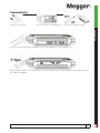
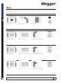
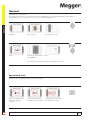
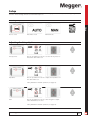
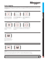
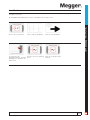
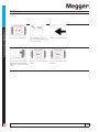
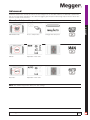
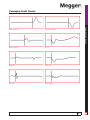
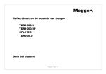
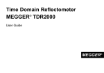
1
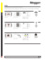
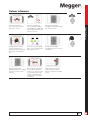
Time Domain Reflectometers
TDR2000/3 - TDR 2000/3P - CFL535G
TDR2010 - TDR2050
User Guide
For all units released after 2014. If your instrument differs significantly from this guide then please use the guide supplied
with your instrument or call technical services for advice.
Safety warnings must be observed during use
Safety Warnings and Battery Information
NOTE - THE INSTRUMENT MUST ONLY BE USED BY SUITABLY TRAINED AND COMPETENT PERSONS
Users of this equipment and/or their employers are reminded that National Health and Safety Legislation requires them to
carry out valid risk assessments of all works so as to identify potential sources of danger and risk.
Please refer to the full list of safety warnings for further information. This was supplied in the box your instrument arrived in
or can also be found on the support CD and is downloadable from the Megger website.
CAT II
Measurement category II: Equipment
connected between the electrical outlets
and the user’s equipment.
CAT III
Measurement category III: Equipment
connected between the distribution
panel and the electrical outlets.
CAT IV
Measurement category IV: Equipment
connected between the origin of the
low-voltage mains supply and the
distribution panel.
Measurement equipment may be safely connected to circuits at the marked rating or lower.
Battery information
This instrument runs on a Lithium Ion battery which should be maintained to maximise health, reliability and longevity. There
are a few simple things that you can do to help maintain your battery health and power potential.
1. Allow your battery to charge fully before using the instrument. Fully charging the battery before use will ensure it
can perform at peak performance and make maintaining performance easier.
2. Keep your battery charged up whenever possible while in use. A Li-Ion battery prefers frequent top-ups and
should never be left in a flat state for extended periods as this can cause permanent damage.
3. Maintain a charge during storage. If your battery is to be stored for extended periods maintain a charge of 40%,
allowing for some discharge and maintaining the protection circuit.
4. Store your battery in a cool, dry place. Li-ion batteries can get stressed when exposed to heat which can reduce its
life. Do not store above 30°C (86°F) for extended periods.
WEEE Directive
The crossed out wheeled bin symbol placed on Megger products is a reminder not to dispose of the product at the end of its
life with general waste.
Megger is registered in the UK as a Producer of Electrical and Electronic Equipment. The Registration No is WEE/HE0146QT.
For further information about disposal of the product consult your local Megger company or distributor or visit your local
Megger website.
Battery disposal
The crossed out wheeled bin symbol placed on the batteries is a reminder not to dispose of them with general waste at the
end of their life.
This product contains the following batteries Li-ion rechargeable battery.
They are located under the battery cover at the rear of the instrument.
They can be safely removed by following the instructions in the battery replacement section of this guide.
Spent Li-ion batteries packs are classified as Industrial Batteries. For disposal in the UK contact Megger Ltd.
For disposal of batteries in other parts of the EU contact your local Megger branch or distributor.
Megger is registered in the UK as a producer of batteries.
The Registration number is BPRN00142.
For Further information see www.megger.com
www.megger.com
2
2
Battery
2
Features
4
Connectivity
5
Accessories
6
Mounting possibilities
7
Mode
8
General
10
Setup
11
Trace tagging
13
Trace functions (TDR2050 only)
14
Zoom
18
Advanced
19
Battery
20
Results
21
Tools
22
Colour schemes
23
Glossary
24
Troubleshooting
25
Common fault traces
27
Specifications
28
Repair and warranty, Calibration, service and spare parts
29
www.megger.com
3
Contents
Safety
Hold
Mode
Features
Accept
Selection
Navigation
Standby
Back
Standard
tripod mount
Battery
Battery
Access
www.megger.com
4
Connectivity
Used for PC connectivity.
Lift cover for access – avoid stressing.
Power lead dependant on region.
Connectivity
The main connectivity is made via standard 4 mm test leads plugged into the dual channel ports.
Using the supplied adapter, connectivity can also be made to the dual F-type ports. Other standard push-on adapters also fit.
Not available on TDR2050.
www.megger.com
5
Accessories
Accessories
6231-652
6231-654
1002-015
Single miniature clip lead set 4mm
Dual miniature clip lead set 4mm
Single Fused test leads
1002-136
6231-655
6231-653
Dual Fused test leads
Bed of Nails Test Leads (1 Pair)
Bed of Nails Test Leads (2 Pairs)
1003-352
1002-552
1003-218
Mains Charger
Replacement Battery
Terminal adaptor kit
www.megger.com
6
There are various mounting and carrying options for the TDR2000 series to ensure the user can position their instrument
securely and efficiently.
Mounting Possibilities
www.megger.com
7
Mode
The TDR2000 series can be set up to work for several different applications. This will allow the user to specify how the
instrument receives, processes and displays test readings. The testing options for each mode are shown on the line adjacent
to the icon for the specific mode.
Mode
Selecting Mode
Change mode
Press to select
Use cursor keys
Single Channel mode
Choose T1 or T2
Press key indicated to change
Dual Channel mode
Choose T1-T2, T2-T1, T1&T2
Press key indicated to change
Crosstalk
Choose T1 or T2
Press key indicated to change
Choosing a mode
www.megger.com
8
Choose T1-M, T2-M, M
Press key indicated to change
Intermittent mode
Choose T1 or T2
Press key indicated to change
Mode
Load saved trace
www.megger.com
9
General
General
General functions are available from the main screen and be accessed using the left and right navigation keys and
appropriate selection buttons.
The instrument is also able to save and preview traces, enabling the user to maintain a database of information for
downloading to a PC to create reports or to use in other custom applications.
Navigation
Use cursor keys
Use soft keys to select
Range
10 m min to 20 km max in 11 steps
(30 - 60,000 ft)
The currently selected range is shown at top right of the screen
Operational state
The current operational state is shown at the top left of the screen and identifies the current operational setting for the
chosen screen. Icons displayed are specific to the function.
Current operational state.
Currently in Manual
operation
www.megger.com
Current operational state.
Currently in Setup operation
Change current state using
the appropriate button
10
Setup
The user has the ability to change various settings for the live trace ranging from the velocity factor to the gain applied to
the trace. These settings can be accessed via the setup icon.
Accessing Setup
Setup
Press to select
Automatic mode
Manual mode
Adjusting the Setup Options
Velocity Factor
Use the up and down cursors to set the Velocity Factor to
match the cable under test.
Impedance
Use the up and down cursors to adjust the impedance for
the cable under test.
*Only available in manual operation (see page 13).
Gain
Use the up and down cursors to alter the gain to adjust
visible disturbances on trace.
*Only available in manual operation (see page 13).
www.megger.com
11
Setup
Pulse width
Use the up and down cursors to change the instrument
pulse width.
*Only available in manual operation (see page 13).
Cable Range
Use the up and down cursors to change the length of the
cable under test.
Saving Current Trace
Save
Preview
Selected trace displayed
Manage Memory
Use cursor keys
Selecting the tick saves
the results to the selected
memory location and the bin
deletes the result from the
selected memory location
www.megger.com
12
Trace tagging
Trace Tagging is only available on the TDR2010 and TDR2050 models. Trace Tagging allows the user to add a name to all
saved traces. This could be the circuit ID, building name or any other identifying text the user wishes to save with the trace.
A text string of up to 32 alphanumeric characters can be stored against each trace and this can consist of upper case letters
including accents.
Use the navigation buttons
to select a letter and the soft
keys to action
You can also press the
OK button to accept the
selection
Press the shift icon to change Press the backspace icon to
the keyboard to the extended delete the last character
characters
Trace Tagging
This function is activated
when choosing a memory
location to save a trace to
Press the hand icon to
add the currently selected
character
Once all characters have
been chosen, press the save
icon to complete the save
process
You can edit a current trace tag either when you save a trace, or when you are choosing a trace for a memory mode
function.
Once you enter edit mode, simply use the technique for new trace tags in the previous section.
When you have finished editing, press the save icon to complete the edit and save your changes.
www.megger.com
13
Trace functions (TDR2050 only)
Trace Functions (TDR2050 only)
TDR2050 has a suite of trace tools which provide additional test capabilities. These can be found in the Trace Tools menu
item.
Press to access Trace Tools
Choose required function
Standard trace function
The standard trace function allows the instrument to be set up to work as a standard pulse TDR. This function should be
chosen to turn off other trace functions.
Standard trace function
www.megger.com
Change settings as required
Press to choose another trace
function
14
AutoFind
AutoFind allows the automatic detection of disturbances along the result trace, making it easier to target disturbances
amongst a noisy trace.
On TDR2000/3 and TDR2010 this function is avaliable from the main screen.
Cursor snaps to disturbance
Trace Functions (TDR2050 only)
Press to choose AutoFind
Press for next disturbance
To cancel the next
The Trace Tools icon will then Press choose another trace
disturbance feature, press the show
function
back button to return to the
main screen
www.megger.com
15
FindEnd
Trace Functions (TDR2050 only)
The FindEnd function allows the automatic detection of the end of the cable. On busy or noisy cables this may need to be
repeated.
Press to choose FindEnd
Automatically positions a
Press to repeat detect end.
cursor at the detected end of
the current cable
To cancel the repeat detect
end feature, press the back
button to return to the main
screen
The Trace Tools icon will then Press choose another trace
show
function
www.megger.com
16
Distance dependent gain - DDG
DDG counteracts the effects of signal loss on a cable by gradually increasing the gain along the trace result. DDG is suitable
for longer length cables and is available on ranges of 1000m and above.
Adjust DDG.
Single press increments by
0.1 dB
Press and hold increments by
0.5 DB
Press choose another trace
function
Step TDR feature
The injected signal is started and then maintained at the same level giving a constant signal. The receiver is also constantly
set to receive any reflections. This function is ideal for near-end testing as it is more sensitive than a Pulse TDR due to
the constant signal. The Step TDR function is only suitable for shorter length cables and is available on ranges up to and
including 500m.
Step TDR function activation
www.megger.com
Change settings as for pulse
TDR
Press choose another trace
function
17
Trace Functions (TDR2050 only)
Distance dependent gain
Zoom
Zoom
The zoom capabilities are limited by the range chosen and only zoom modes suitable for the chosen ranges are displayed.
Zoom function
www.megger.com
Press to select
Zooms at cursor position
Minimum range
Range/Capability
18
Advanced
The TDR2000 series have two methods of operation. Both options allow the user to set operational parameters.
In Manual operation the user has full control over the settings in use for the cable under test. In Automatic operation the
TDR sets the appropriate impedance to the cable and suggests gain and pulse width settings. Expert Function allows auto
detection of faults on the live traces.
Manual and Automatic operation
Press to swap modes
Manual
Adjustable in this mode
Automatic
Adjustable in this mode
Advanced
Manual/Automatic
Changes with each press
NOTE: Auto in DDG only performs AutoZ; not ‘auto settings’
www.megger.com
19
Battery
The TDR2000 series have built in intelligent charge management technology so that the maximum charge rate is
maintained, meaning a longer battery life is possible.
Battery
Battery information
Battery state
Capacity
Typical life remaining
Warnings
Charging
Charging paused
Charged
www.megger.com
20
Results
The cursor lines on the TDR2000 series allow the user to identify disturbances at strategic points to determine distances and
positions of potential faults on the trace.
Cursors and measurements
Results
Cursor choice
Press to select
Swap between cursors
Cursor movement
C1-C2 Trace 1
(Single Trace Mode)
C3-C4 Trace 2
(Dual Trace Mode)
Use cursor keys
Cursor position on trace
Distance measurement
Distance to cursor
Delta measurement
www.megger.com
21
Tools
When in the Setup screen, access can be made to a selection of user tools. Within the tools function the user can change
basic settings and locate current instrument setup information.
Tools
Adjustable setting include Volume, Standby, Units of measure, NVP formats, Colour scheme, Brightness and Language.
Preferences
Use cursor keys
Up/Down to select
Left/Right to change
Help
Use cursor keys
Function information
Custom
Press to select
Left/Right to select
Up/Down to change
www.megger.com
22
Colour schemes
There are a number of
colour schemes available
as standard, plus additional
custom schemes where you
can set your own
Use the left and right
navigation buttons to change
the current scheme
You can use the current
scheme as a basis for a
custom scheme by pressing
the custom scheme pallet
icon
From here you can change
any of seven elements that
make up all screens
Use the left and right
navigation buttons to choose
an element
Use the up and down
navigation buttons to change
the colour for the chosen
element
Once finished setting your
colours, press either the
custom 1 or custom 2 icons
to save that scheme. The
scheme currently stored
in that custom slot will be
overwritten.
After saving your custom
scheme, press the back
button to return to the main
screen
www.megger.com
Colour Schemes
Press the preferences
icon to access the system
preferences screen
23
Glossary
Appendix A
Glossary
Function
Z
Mode
Preferences
Impedance
Single channel mode
Settings
Gain
Dual channel mode
Auto/Manual choice
Pulse Width
Intermittent mode
Press for next fault
Range
Crosstalk
Delete
Edit Trace Tag
Save
Accept
Select current character
Load saved trace
Preview
Shift character set
Cursor controls
T1 Trace 1
Backspace delete
Zoom function
T2 Trace 2
Complete and save
Help
M
Memory
Trace Functions
Trace Functions
Standard Trace
AutoFind function
FindEnd
DDG
Step Trace
Preferences
Speaker
On/Off
Velocity format
Ratio
Brightness
1 - 10
m/µs
Power down timer
ft/µs
1, 5, 10 min, Never
Language
English
Dutch
Unit of measurement
Colour scheme
Swedish
Meters
Default/Outdoor
Spanish
Feet
Scheme 1 - 6
Italian
Nanoseconds
Custom 1 - 2
German
French
www.megger.com
24
TroubleShooting
Appendix B
Fault
Problem
Solution
Instrument won’t turn on
Battery not charged up
TroubleShooting
Plug in charger and charge for 6 hours.
Instrument won’t charge
Battery not functioning (Flashing charge icon)
Contact your local Megger dealer for a replacement battery.
Instrument won’t charge
Charger not functioning (LED)
Contact your local Megger dealer for a replacement charger.
Instrument keeps turning itself off
Battery not sufficiently charged
Plug in charger and charge for 6 hours
Instrument keeps turning itself off
Standby set too low
Access user settings and change standby time.
Display not visible
Colour settings incorrect
Access user settings and change colours.
Display not visible
Instrument in power save mode
Press standby button to return to display.
Distance to fault is inaccurate
Incorrectly set Velocity Factor
Check VF value for the cable under test and change settings.
Can’t set Velocity Factor
Cable Velocity Factor unknown
Test a known length of cable to determine Velocity Factor.
VF, Impedance, Gain, Pulse inaccessible
Instrument set to Automatic
Press the escape button and then change to manual.
Instrument keeps ticking
Dual input function chosen
Ticking is normal due to relays switching input.
www.megger.com
25
TroubleShooting
Appendix B
Fault
Problem
Solution
TroubleShooting
Instrument keeps ticking on single input
Incorrect connection to cable under test
End of cable not determined so unable to reach max range.
Buttons not responding
Keypad error
Contact Megger for repair.
Can’t see end of cable on trace
Wrong range chosen
From main screen press up navigation button to extend range.
Can’t see fault I know is there
Gain set too low
In manual mode select and change gain with navigation buttons.
The trace is very noisy
Gain set too high
In manual mode select and change gain with navigation buttons.
No trace even though leads connected
Leads plugged in to wrong channel
Connect test leads to correct channel.
Instrument not uploading/downloading
USB cable damaged or wrong type
Use only genuine Megger cable and check before connecting.
Instrument won’t download data
No saved results on TDR
Take readings and save results before download.
TraceXpert won’t load up
Incorrect or unstable installation
Obtain correct user rites if required and re-install TraceXpert.
TraceXpert won’t install on PC
Incompatible operating system
TraceXpert is compatible with Windows XP, Vista, 7 and 8.
www.megger.com
26
Common fault traces
Appendix C
Shorted conductor
Cable splice/joint
T-joint
Bridge tap
Spilt/resplit
Wet splice
Water ingress
www.megger.com
Common fault traces
Open conductor
27
Specifications
Except where otherwise stated, this specification applies at an ambient temperature of 20ºC
General
Range
Up to 20000m with a minimum resolution of 0.1m
Accuracy
±1% of range ± 1 pixel at 0.67VF
Specifications
Note- The measurement accuracy is for the indicated cursor position only and is conditional on the velocity factor being
correct
Resolution
1% of range
Input Protection
This instrument complies with IEC61010-1 to protect the user in the event of connection to
live systems. TDR2050 is rated at 600 V CAT IV whilst all other models are rated at
150 V CAT IV. TDR2050 is specifically designed to allow use on energised systems up to the
rated voltage.
All other models are designed for use on de-energised systems and Megger fused leads
must be used on power cables.
Output pulse
Up to 20 volts peak to peak into open circuit. Pulse widths determined by
range, cable and model used.
Gain
Set for each range with user selectable steps (in Manual operating mode)
Velocity Factor
Variable from 0.2 to 0.99 in steps of 0.01
TX Null
Automatic mode
Trace Tagging 32 alphanumeric characters chosen from upper case letters including accents
Colour schemes Selectable
TDR2000/3 x2
TDR2010, TDR2050 x8
Custom
TDR2000/3 x1
TDR2010, TDR2050 x2
Step TDR Eliminates the Dead Zone effect.
DDG Available in ranges 1000 m and above
Adjust DDG.
Single press increments by 0.1 dB
Press and hold increments by 0.5 DB
Cable Impedance 25, 50, 75, 100, 125, 140 ohm + AUTO (model dependent)
Power Down
User programmable auto power off timer 1, 5, 10 minutes or off
Batteries
Li-Ion rechargeable battery with 12 hours typical life
Safety
IEC61010-1 compliant for live systems. TDR2050 600 V CATIV
All other models 150 V CAT IV or 300 V CAT III.
EN60950-1, EN61010-1, UN38.3 and EN62133
EMC
Complies with Electromagnetic Compatibility Specifications BS EN 61326-1,
B min. for all immunity tests
Mechanical
The instrument is designed for use indoors or outdoors and is rated to IP54
Case Dimensions
290 mm (11.4 inches) x 190 mm (7.5 inches) x 55 mm (2.2 inches)
Instrument weight
1.7 kg (3.8lbs)
Case material
ABS
Display
800 x 480 pixel WVGA colour graphics LCD, viewable in external environments,
user selectable colour schemes
Connectors
Four 4mm-safety terminals and two F connectors.
Other standard push on adapters will fit. F connectors not available on TDR2050
Test leads
TDR2000/3, TDR2010
2 m 2 x 4 mm shrouded connector to miniature crocodile clips
TDR2000/3P, TDR2050
2 x 1.5 m fused leads
CFL535G
2 x Bed-of-Nails lead set
www.megger.com
28
Environmental
Operational Temperature
-15ºC to +50ºC (5ºF to 122ºF)
Storage Temperature
-20ºC to 70ºC (-4ºF to 158ºF)
Charging Temperature
0ºC to 40ºC
Repair and warranty
New instruments are covered by a two year warranty from the date of purchase by the user, the second year being
conditional on the free registration of the product on www.megger.com. You will need to log in, or first register and then
login to register your product. The second year warranty covers faults, but not recalibration of the instrument which is only
warranted for one year. Any unauthorised prior repair or adjustment will automatically invalidate the warranty.
These products contain no user repairable parts and if defective should be returned to your supplier in original packaging or
packed so that it is protected from damage during transit. Damage in transit is not covered by this warranty and replacement/
repair is chargeable.
Megger warrants this instrument to be free from defects in materials and workmanship, where the equipment is used for
its proper purpose. The warranty is limited to making good this instrument (which shall be returned intact, carriage paid,
and on examination shall disclose to their satisfaction to have been defective as claimed). Any unauthorised prior repair or
adjustment will invalidate the warranty. Misuse of the instrument, from connection to excessive voltages, fitting incorrect
fuses, or by other misuse is excluded from the warranty. The instrument calibration is warranted for one year.
This Warranty does not affect your statutory rights under any applicable law in force, or your contractual rights arising from a
sale and purchase contract for the product. You may assert your rights at your sole discretion
Calibration, service and spare parts
For service requirements for Megger Instruments contact Megger or your local distributor or authorised repair centre.
Megger operates fully traceable calibration and repair facilities, ensuring your instrument continues to provide the high
standard of performance and workmanship you expect. These facilities are complemented by a worldwide network of
approved repair and calibration companies to offer excellent in-service care for your Megger products.
See the back of this user guide for Megger contact details.
Details of your Authorised Service Centre is available by contacting [email protected] and giving details of your
location.
www.megger.com
29
Repair and Warranty, Calibration, Service and Spare Parts
If the protection of an instrument has been impaired it should not be used, but sent for repair by suitably trained and
qualified personnel. The protection is likely to be impaired if, for example, the instrument shows visible damage, fails to
perform the intended measurements, has been subjected to prolonged storage under unfavourable conditions, or has been
exposed to severe transport stresses.
Megger Limited
Archcliffe Road
Dover Kent, CT17 9EN
England
Tel: +44 (0) 1304 502100
Fax: +44 (0) 1304 207342
Megger
4271 Bronze Way
Dallas, TX 75237-1017 U.S.A.
Tel: +1 (800) 723-2861 (U.S.A. only)
Tel: +1 (214) 330-3203 (International)
Fax: +1 (214) 337-3038
Megger
Valley Forge Corporate Center
2621 Van Buren Avenue
Norristown, PA 19403, USA
Tel: +1 (610) 676-8500
Fax: +1 (610) 676-8610
Megger SARL
Z.A. Du Buisson de la Couldre
23 rue Eugène Henaff
78190 TRAPPES
France
Tel : +33 (1) 30.16.08.90
Fax : +33 (1) 34.61.23.77
Megger GmbH
Obere Zeil 2
61440 Oberursel
Germany
Tel: +49 6171-92987-0
Fax: +49 6171-92987-19
Megger Sweden AB
Rinkebyvägen 19
182 36 Danderyd
Tel: +46 8 510 195 00
Fax: +46 8 510 195 95
Seba Hungária Kft.
1027 Budapest, Vitéz u. 14/a.
Magyarország
Tel./FAX: +36 1 214-2512
Mobil: +36 20 9654-297
Megger Pty Limited
Unit 26 9 Hudson Avenue
Castle Hill
Sydney NSW 2125 Australia
T +61 (0)2 9659 2005
F +61 (0)2 9659 2201
Megger Limited
Unit 106-550 Alden Road
Markham, Ontario L3R6A8
Canada
T +1 416 298 9688 (Canada only)
T +1 416 298 6770
F +1 416 298 0848
This instrument is manufactured in the United Kingdom.
The company reserves the right to change the specification or design without prior notice.
Megger is a registered trademark
www.megger.com
TDR20003--TDR20003P--TDR2010--TDR2050--CFL525G_UG_EN_V01