1
Over 100 years cumulative experience
24 hour rush turnaround / technical support service
Established in 1993
The leading independent repairer of servo motors and drives in North America.
Visit us on the web:
www.servo-repair.com
www.servorepair.ca
www.ferrocontrol.com
www.sandvikrepair.com
www.accuelectric.com
Scroll down to view your document!
For 24/7 repair services :
USA: 1 (888) 932 - 9183
Canada: 1 (905) 829 -2505
Emergency After hours: 1 (416) 624 0386
Servicing USA and Canada
YASNAC PC NC
Connecting Manual
Version: Beta 1.0
YASNAC PCNC Connecting Manual
Preface/Table of Contents
SAFETY INFORMATION
PRECAUTIONS
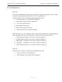
1. Read this instruction manual in its entirety before using the YASNAC PC NC Connecting Manual.
2. The following warning symbols are used to indicate precautions that the user must be aware of
to safely use this equipment. Failure to follow these precautions can result in serious or possibly
even fatal injury and damage to products or related equipment or system.
WARNING
This symbol indicates the presence of a potentially hazardous condition which, if not avoided,
could result in serious personal injury or death.
This precautionary symbol appears in labels attached to YASNAC products to alert the user to
conditions requiring concern for safety.
SPECIAL SAFETY NOTE: This symbol indicates that ELECTRICAL SHOCK HAZARD
condition exists. DO NOT TOUCH any electrical connection terminals when the power is ON,
and for at least 5 minutes after switching off the power supply.
CAUTION
This symbol indicates the presence of a potentially hazardous condition which, if not avoided,
could result in minor or moderate personal injury and/or damage to equipment.
NOTICE
Printed _______. 1999. The information contained within this document is the proprietary property of
Yasakawa Electric America, Inc., and may not be copied, reproduced or transmitted to other parties without
the expressed written authorization of Yasakawa Electric America, Inc.
No pattent liability is assumed with respect to the uses of the information contained herein. Moreover,
because Yaskawa is constantly improving its high quality product, the information contained in this manual
is subject to change without notice. Every precaution has been taken in the preparation of this document.
Nevertheless, Yasakawa assumes no responsibility for damages resulting from the use of the information
contained within this publication.
i
YASNAC PCNC Connecting Manual
Preface/Table of Contents
Table of Contents
1. GENERALS
1.1
System Configuration . . . . . . . . . . . . . . . . . . . . . . . . . . . . . . . . . . . . . . . . . . . . . . 1 - 2
1.1.1
System Configuration . . . . . . . . . . . . . . . . . . . . . . . . . . . . . . . . . . . . . . . . 1 - 2
1.1.2
Connection between Devices . . . . . . . . . . . . . . . . . . . . . . . . . . . . . . . . . . 1 - 3
1.1.3
Connector Layout NC side . . . . . . . . . . . . . . . . . . . . . . . . . . . . . . . . . . . . 1 - 4
1.1.4
Connector Layout PC side . . . . . . . . . . . . . . . . . . . . . . . . . . . . . . . . . . . . 1 - 5
1.2
General Specifications . . . . . . . . . . . . . . . . . . . . . . . . . . . . . . . . . . . . . . . . . . . . . 1 - 6
1.3
Thermal Design of Enclosure . . . . . . . . . . . . . . . . . . . . . . . . . . . . . . . . . . . . . . . . 1 - 7
1.3.1
Thermal Design . . . . . . . . . . . . . . . . . . . . . . . . . . . . . . . . . . . . . . . . . . . . . 1 - 7
1.3.2
Dust Proof Design . . . . . . . . . . . . . . . . . . . . . . . . . . . . . . . . . . . . . . . . . . . 1 - 11
1.3.3
Countermeasure Against Magnetic Fields . . . . . . . . . . . . . . . . . . . . . . . . 1 - 12
1.4
Cable Clamp and Shielding. . . . . . . . . . . . . . . . . . . . . . . . . . . . . . . . . . . . . . . . . . 1 - 13
1.5
Packaging . . . . . . . . . . . . . . . . . . . . . . . . . . . . . . . . . . . . . . . . . . . . . . . . . . . . . . . 1 - 14
1.5.1
General Notes . . . . . . . . . . . . . . . . . . . . . . . . . . . . . . . . . . . . . . . . . . . . . . 1 - 14
1.5.2
Installation of CNC Unit . . . . . . . . . . . . . . . . . . . . . . . . . . . . . . . . . . . . . . 1 - 15
1.5.3
Installation of Feed/Spindle Servopacks. . . . . . . . . . . . . . . . . . . . . . . . . . 1 - 16
2. POWER SUPPLY CONNECTIONS
2.1
2.2
Connection between Devices . . . . . . . . . . . . . . . . . . . . . . . . . . . . . . . . . . . . . . . . 2 - 2
2.1.1
Power Supply specifications for PCNC and I/O units . . . . . . . . . . . . . . 2 - 2
2.1.2
Power Supply connections to PCNC
2.1.3
Power Supply Connections to PCNC and I/O units . . . . . . . . . . . . . . . . . 2 - 3
2.1.4
Power Supply to Converter unit . . . . . . . . . . . . . . . . . . . . . . . . . . . . . . . . 2 - 4
........................... 2-3
Detailed Connections . . . . . . . . . . . . . . . . . . . . . . . . . . . . . . . . . . . . . . . . . . . . . . 2 - 5
2.2.1
Power Supply to PCNC unit . . . . . . . . . . . . . . . . . . . . . . . . . . . . . . . . . . . 2 - 5
ii
YASNAC PCNC Connecting Manual
2.3
Preface/Table of Contents
2.2.2
Power Supply to Converter . . . . . . . . . . . . . . . . . . . . . . . . . . . . . . . . . . . . 2 - 7
2.2.3
Example of Circuit Diagram . . . . . . . . . . . . . . . . . . . . . . . . . . . . . . . . . . 2 - 8
LED for Power Input /Output . . . . . . . . . . . . . . . . . . . . . . . . . . . . . . . . . . . . . . . . 2 - 9
2.3.1
LED for PCNC Power Input . . . . . . . . . . . . . . . . . . . . . . . . . . . . . . . . . . . 2 - 10
3. CONNECTION OF PCNC OPERATION PANEL
3.1
Connection between Devices . . . . . . . . . . . . . . . . . . . . . . . . . . . . . . . . . . . . . . . . . . 3 - 2
3.1.1
3.2
Detailed Connection of PCNC Operation panel . . . . . . . . . . . . . . . . . . . . . . . . . . . . 3 - 3
3.2.1
3.3
Connection with the Operation panel . . . . . . . . . . . . . . . . . . . . . . . . . . . . . . 3 - 2
Connection with Operation panel . . . . . . . . . . . . . . . . . . . . . . . . . . . . . . . . . 3 - 3
General notes on Connection with operation Panel . . . . . . . . . . . . . . . . . . . . . . . . . 3 - 8
3.3.1
JANCD-JSPO4/JANCD-J861. . . . . . . . . . . . . . . . . . . . . . . . . . . . . . . . . . . . 3 - 8
3.3.2
PCNC Connections Layout . . . . . . . . . . . . . . . . . . . . . . . . . . . . . . . . . . . . . . 3 - 9
4. CONNECTION OF MANUAL PULSE GENERATOR
4.1
Connection between Devices . . . . . . . . . . . . . . . . . . . . . . . . . . . . . . . . . . . . . . . . 4 - 2
4.1.1
4.2
Connection with CNC Operation Panel . . . . . . . . . . . . . . . . . . . . . . . . . . 4 - 2
Detailed Connection of Manual Pulse Generator . . . . . . . . . . . . . . . . . . . . . . . . . 4 - 3
4.2.1
Parallel I/F. . . . . . . . . . . . . . . . . . . . . . . . . . . . . . . . . . . . . . . . . . . . . . . . . 4 - 3
4.2.2
Non-Parallel I/F . . . . . . . . . . . . . . . . . . . . . . . . . . . . . . . . . . . . . . . . . . . . 4 - 4
5. CONNECTION OF POWER ON/OFF EXCLUSIVE SIGNAL
5.1
Connection between Devices . . . . . . . . . . . . . . . . . . . . . . . . . . . . . . . . . . . . . . . . 5 - 2
5.1.1
5.2
Detailed Connection of Power ON/OFF Exclusive Signal . . . . . . . . . . . . . . . . . . 5 - 3
5.2.1
5.3
Connection to PCNC Unit. . . . . . . . . . . . . . . . . . . . . . . . . . . . . . . . . . . . . 5 - 2
Connection to PCNC Unit. . . . . . . . . . . . . . . . . . . . . . . . . . . . . . . . . . . . . 5 - 3
Details of Signal . . . . . . . . . . . . . . . . . . . . . . . . . . . . . . . . . . . . . . . . . . . . . . . . . . 5 - 4
iii
YASNAC PCNC Connecting Manual
Preface/Table of Contents
5.3.1
Servo Power ON (SVMX), Brake Release (BKX) Output . . . . . . . . . . . . 5 - 4
5.3.2
Emergency Stop (*ESP) Input . . . . . . . . . . . . . . . . . . . . . . . . . . . . . . . . . 5 - 5
5.3.3
External Power ON/OFF (EON, EOF, ECOM) Input. . . . . . . . . . . . . . . . 5 - 5
6. CONNECTION WITH SERVOPACK
6.1
Connection between Devices . . . . . . . . . . . . . . . . . . . . . . . . . . . . . . . . . . . . . . . . 6 - 2
6.1.1
6.2
Connection between PCNC Unit, Servopack and Motor . . . . . . . . . . . . . 6 - 2
Connection Details . . . . . . . . . . . . . . . . . . . . . . . . . . . . . . . . . . . . . . . . . . . . . . . . 6 - 3
6.2.1
Connection between PCNC Unit and Servopack . . . . . . . . . . . . . . . . . . . 6 - 3
6.2.2
Connection of the Servomotor . . . . . . . . . . . . . . . . . . . . . . . . . . . . . . . . . 6 - 4
6.2.3
Connection of the Spindle Motor . . . . . . . . . . . . . . . . . . . . . . . . . . . . . . . 6 - 7
6.2.4
Selection of the Converter. . . . . . . . . . . . . . . . . . . . . . . . . . . . . . . . . . . . . 6 - 9
7. CONNECTION OF RS-232C
8. CONNECTION OF DIRECT IN/OUT SIGNALS TO THE PCNC UNIT
8.1
Connection between Devices . . . . . . . . . . . . . . . . . . . . . . . . . . . . . . . . . . . . . . . . 8 - 2
8.1.1
8.2
Connection to the CNC Unit . . . . . . . . . . . . . . . . . . . . . . . . . . . . . . . . . . . 8 - 2
Detailed Connection of Direct IN/OUT . . . . . . . . . . . . . . . . . . . . . . . . . . . . . . . . 8 - 2
8.2.1
Connection to the CNC Unit . . . . . . . . . . . . . . . . . . . . . . . . . . . . . . . . . . . 8 - 2
8.2.2
Description of Signal . . . . . . . . . . . . . . . . . . . . . . . . . . . . . . . . . . . . . . . . 8 - 4
8.2.3
I/O Circuits on CNC side . . . . . . . . . . . . . . . . . . . . . . . . . . . . . . . . . . . . . 8 - 4
9. CONNECTION OF I/O MODULE
9.1
Connection between Devices . . . . . . . . . . . . . . . . . . . . . . . . . . . . . . . . . . . . . . . . 9 - 2
9.1.1
Connection between Units . . . . . . . . . . . . . . . . . . . . . . . . . . . . . . . . . . . . 9 - 2
iv
YASNAC PCNC Connecting Manual
9.2
Detailed Connection of I/O Module . . . . . . . . . . . . . . . . . . . . . . . . . . . . . . . . . . . 9 - 3
9.2.1
9.3
Connection between Units . . . . . . . . . . . . . . . . . . . . . . . . . . . . . . . . . . . . 9 - 3
Connection between Additional I/O Module devices . . . . . . . . . . . . . . . . . . . . . . 9 - 4
9.3.1
9.4
Preface/Table of Contents
Connection between Units . . . . . . . . . . . . . . . . . . . . . . . . . . . . . . . . . . . . 9 - 4
Detailed Connection of Additinal I/O Module . . . . . . . . . . . . . . . . . . . . . . . . . . . 9 - 5
9.4.1
Connection between Units . . . . . . . . . . . . . . . . . . . . . . . . . . . . . . . . . . . . 9 - 5
10. CONNECTION OF GENERAL PURPOSE I/O
10.1
Connection between Devices . . . . . . . . . . . . . . . . . . . . . . . . . . . . . . . . . . . . . . . . 10 - 2
10.1.1 Connection of Signal Line with I/O Module . . . . . . . . . . . . . . . . . . . . . . 10 - 2
10.1.2 Connection between Devices . . . . . . . . . . . . . . . . . . . . . . . . . . . . . . . . . . 10 - 3
10.2
Detailed Connection of General Purpose I/O . . . . . . . . . . . . . . . . . . . . . . . . . . . . 10 - 4
10.2.1 FC810/FC815/FC860 Module . . . . . . . . . . . . . . . . . . . . . . . . . . . . . . . . . 10 - 4
10.2.2 FC861 Module . . . . . . . . . . . . . . . . . . . . . . . . . . . . . . . . . . . . . . . . . . . . . 10 - 27
10.2.3 JSP02/JSP04 Module . . . . . . . . . . . . . . . . . . . . . . . . . . . . . . . . . . . . . . . . 10 - 36
10.3
Description of General Purpose I/O Signal. . . . . . . . . . . . . . . . . . . . . . . . . . . . . . 10 - 45
10.3.1 I/O Port . . . . . . . . . . . . . . . . . . . . . . . . . . . . . . . . . . . . . . . . . . . . . . . . . . . 10 - 45
10.3.2 /O Circuit of I/O Port . . . . . . . . . . . . . . . . . . . . . . . . . . . . . . . . . . . . . . . . 10 - 47
10.3.3 Power Supply for I/O Signal . . . . . . . . . . . . . . . . . . . . . . . . . . . . . . . . . . . 10 - 57
11. REPLACEMENT OF BATTERY/FUSE
11.1
Battery Replacement . . . . . . . . . . . . . . . . . . . . . . . . . . . . . . . . . . . . . . . . . . . . . . . .11 - 2
11.1.1 Checking the battery life . . . . . . . . . . . . . . . . . . . . . . . . . . . . . . . . . . . . . . .11 - 2
11.1.2 Replacement procedure of battery . . . . . . . . . . . . . . . . . . . . . . . . . . . . . . .11 - 3
11.2
Fuse Replacement . . . . . . . . . . . . . . . . . . . . . . . . . . . . . . . . . . . . . . . . . . . . . . . . . .11 - 4
v
YASNAC PCNC Connecting Manual
Preface/Table of Contents
APPENDIX 1. DIMENSIONS
1.1
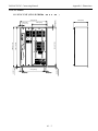
PCNC Module. . . . . . . . . . . . . . . . . . . . . . . . . . . . . . . . . . . . . . . . . . . . . . . . . . . . A1-3
o - oooo - oo )A1-3
1.1.1 PCNC UNIT (JZNC-JPCRKM
1.2
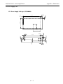
Power Supply Unit . . . . . . . . . . . . . . . . . . . . . . . . . . . . . . . . . . . . . . . . . . . . . . . . A1-4
1.2.1
1.3
Operation Panel . . . . . . . . . . . . . . . . . . . . . . . . . . . . . . . . . . . . . . . . . . . . . . . . . . . A1-5
1.3.1
1.4
Power Supply Unit type ( UPS00004) . . . . . . . . . . . . . . . . . . . . . . . . . . . .A1-4
Display Unit Type ( JZNC-JPCOP-
ooo -oo ) . . . . . . . . . . . . . . . . . . .A1-5
I/O Module . . . . . . . . . . . . . . . . . . . . . . . . . . . . . . . . . . . . . . . . . . . . . . . . . . . . . . A1-6
1.4.1 ANCD-FC810/FC815/FC860 Model-A1-6
1.4.2
JZNC-IAU59 (JANCD-FC861) Model. . . . . . . . . . . . . . . . . . . . . . . . . . . .A1-6
1.5
AC Servopack (including Converter and Spindle Drive) . . . . . . . . . . . . . . . . . . . A1-7
1.6
AC Servomotor S Series (Model SGMG, for 200VAC) . . . . . . . . . . . . . . . . . . . . A1-9
1.7
1.6.1
Standard Specifications. . . . . . . . . . . . . . . . . . . . . . . . . . . . . . . . . . . . . . . .A1-9
1.6.2
Dimensions . . . . . . . . . . . . . . . . . . . . . . . . . . . . . . . . . . . . . . . . . . . . . . . . .A1-10
Spindle Motor M5 Series (Model UAASKA for 200VAC) . . . . . . . . . . . . . . . . . A1-11
1.7.1
Flange-mounted type Motor Dimensions . . . . . . . . . . . . . . . . . . . . . . . . . .A1-11
1.7.2
Foot-mounted type Motor Dimensions(Drwg. 1.1.1) . . . . . . . . . . . . . . . . .A1-13
1.8
Power Supply Unit for Brake (OPR109F, OPR109A) . . . . . . . . . . . . . . . . . . . . . A1-15
1.9
Noise Filter . . . . . . . . . . . . . . . . . . . . . . . . . . . . . . . . . . . . . . . . . . . . . . . . . . . . . . A1-16
1.10
Manual Pulse Generator (OSM-01-2GA-15) . . . . . . . . . . . . . . . . . . . . . . . . . . . . A1-17
1.11
Spindle Pulse Generator . . . . . . . . . . . . . . . . . . . . . . . . . . . . . . . . . . . . . . . . . . . . A1-18
1.11.1 NE-1024-2MDF-068-11 (6000 r/min) . . . . . . . . . . . . . . . . . . . . . . . . . . . .
NE-1024-2MDF-068-12 (6000 r/min) . . . . . . . . . . . . . . . . . . . . . . . . . . . A1-18
1.11.2 NE-1024-2MD-11 (6000 r/min) . . . . . . . . . . . . . . . . . . . . . . . . . . . . . . . . .A1-19
1.12
Heat Exchanger . . . . . . . . . . . . . . . . . . . . . . . . . . . . . . . . . . . . . . . . . . . . . . . . . . . A1-20
1.12.1 External Dimensions of REX1550 . . . . . . . . . . . . . . . . . . . . . . . . . . . . . . .A1-20
1.12.2 HEATEX02 . . . . . . . . . . . . . . . . . . . . . . . . . . . . . . . . . . . . . . . . . . . . . . . . .A1-21
1.13
AC Reator (UZBA-B: for Input, for 50.60Hz) . . . . . . . . . . . . . . . . . . . . . . . . . . . A1-22
vi
YASNAC PCNC Connecting Manual
Preface/Table of Contents
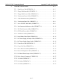
APPENDIX 2.CABLE SPECIFICATIONS
2.1
2.2
2.3
Cable Manufacturing Drawings . . . . . . . . . . . . . . . . . . . . . . . . . . . . . . . . . . . . . . .A2-3
2.1.1
Connection with the Power Supply. . . . . . . . . . . . . . . . . . . . . . . . . . . . . . .A2-3
2.1.2
Connection with the Operation Panel . . . . . . . . . . . . . . . . . . . . . . . . . . . . .A2-5
2.1.3
Connection with the Pulse Generator . . . . . . . . . . . . . . . . . . . . . . . . . . . . .A2-11
2.1.4
Connection with the Power ON/OFF Circuit . . . . . . . . . . . . . . . . . . . . . . .A2-11
2.1.5
Connection of the Direct IN Signals . . . . . . . . . . . . . . . . . . . . . . . . . . . . . .A2-12
2.1.6
Connection with I/O Boards . . . . . . . . . . . . . . . . . . . . . . . . . . . . . . . . . . . .A2-12
2.1.7
Connection between I/O Boards . . . . . . . . . . . . . . . . . . . . . . . . . . . . . . . . .A2-13
2.1.8
Connection with the Servo Unit . . . . . . . . . . . . . . . . . . . . . . . . . . . . . . . . .A2-15
Cable Specifications . . . . . . . . . . . . . . . . . . . . . . . . . . . . . . . . . . . . . . . . . . . . . . . .A2-17
2.2.1
Cable Drwg. No. DE 8400093 (KQVV-SB Type, 0.2mm2 x 20 pairs) . . .A2-17
2.2.2
Cable Drwg. No. DE 8402398 (VCT Type, 0.2mm2 x 5 pairs) . . . . . . . . .A2-18
2.2.3
Cable Drwg. No. DE9405671 . . . . . . . . . . . . . . . . . . . . . . . . . . . . . . . . . . .A2-19
Cable and Connector Details. . . . . . . . . . . . . . . . . . . . . . . . . . . . . . . . . . . . . . . . . A2-2
2.3.1
Main Power Cable (UWR00264-1) . . . . . . . . . . . . . . . . . . . . . . . . . . . . . .A2-3
2.3.2
Floppy Disk data cable (UWR00265-1) . . . . . . . . . . . . . . . . . . . . . . . . . . .A2-4
2.3.3
Floppy Disk Power Cable (UWR00266-1 ) . . . . . . . . . . . . . . . . . . . . . . . .A2-5
2.3.4
Touchscreen Power Cable (UWR00267-1). . . . . . . . . . . . . . . . . . . . . . . . .A2-6
2.3.5
Video Extension cable (UWR00270-1) . . . . . . . . . . . . . . . . . . . . . . . . . . .A2-7
2.3.6
Touchscreen Data Cable (UWR00271-1 ) . . . . . . . . . . . . . . . . . . . . . . . . .A2-8
2.3.7
Servo ON/OFF Main Cable (UWR00272-1 ) . . . . . . . . . . . . . . . . . . . . . . .A2-9
2.3.8
Push-button switch harness cable (UWR00273-1) . . . . . . . . . . . . . . . . . . .A2-10
2.3.9
PS/2 Port Extension Cable (UWR00275-1 ). . . . . . . . . . . . . . . . . . . . . . . .A2-11
2.3.10 CPU Rack Power cable (UWR00276-1) . . . . . . . . . . . . . . . . . . . . . . . . . .A2-12
vii
YASNAC PCNC Connecting Manual
Preface/Table of Contents
2.3.11 CRT Power Cable (UWR00262-1) . . . . . . . . . . . . . . . . . . . . . . . . . . . . . . .A2-13
2.3.12 Serial Mouse Data Cable (UWR00318-1) . . . . . . . . . . . . . . . . . . . . . . . . .A2-14
2.3.13 NC Power Supply AC Input Cable (UWR00229-1) . . . . . . . . . . . . . . . . . .A2-15
2.3.14 NC Power Supply Output Cable (UWR00228-3). . . . . . . . . . . . . . . . . . . .A2-16
2.3.15 Yenet Servo Cable (UWR00249-2). . . . . . . . . . . . . . . . . . . . . . . . . . . . . . .A2-17
2.3.16 Yenet I/O Cable (UWR00251-4). . . . . . . . . . . . . . . . . . . . . . . . . . . . . . . . .A2-18
2.3.17 Servo Drive I/O Cable (UWR00214-2) . . . . . . . . . . . . . . . . . . . . . . . . . . .A2-19
2.3.18 Power ON Sequence Cable (UWR00263-1). . . . . . . . . . . . . . . . . . . . . . . .A2-20
2.3.19 I/O Board Power Output Cable (UWR00258-7). . . . . . . . . . . . . . . . . . . . .A2-21
2.3.20 Drive Jumper Connectors (UWR00219-2) . . . . . . . . . . . . . . . . . . . . . . . . .A2-22
2.3.21 I/O Cable (UWR00305-7). . . . . . . . . . . . . . . . . . . . . . . . . . . . . . . . . . . . . .A2-23
2.3.22 I/O Cable (UWR00306-3). . . . . . . . . . . . . . . . . . . . . . . . . . . . . . . . . . . . . .A2-24
2.3.23 I/O Cable (UWR00307-3). . . . . . . . . . . . . . . . . . . . . . . . . . . . . . . . . . . . . .A2-25
viii
YASNAC PCNC Connecting Manual
Preface/Table of Contents
USING THIS MANUAL
This manual decribes the procedures for connecting the<$61$&3&1& to machines, machine interfaces and
peripheral equipment.
Connections provided by the machine tool builder differ from the types provided in Yaskawa CNC enclosures. Therefore, it may be necessary to make connection changes in accordance with the needs of standard
cabinets and integrated equipment.
The programmable controller system (hereafter called PLC) is installed in the <$61$&3&1& unit.
For PLC details, refer to the<$61$&3&1& PLC Programming Manual.
RELATED INFORMATION SOURCES
For additonal information, refer to the following manuals:
Title Of Document
Contents
YASNAC PCNC Operating Manual
( YEA-SIA-C844-2.1 )
Basic configuration and operating procedures
also describes Human machine interface(HMI)
YASNAC PCNC Programming Manual
( YEA-SIA-C844-2.2 )
PCNC Program creation instructions
YASNAC PCNC PLC Programming Manual
( YEA-SIA-C844-0.1 )
PLC Program creation instructions
YASNAC PCNC I/O Signal Function
( YEA-SIA-C844-2.3 )
Describes functions between PCNC, PLC
and Machine Tool
YASNAC PCNC Connecting Manual
( YEA-SIA-C844-0.2 )
Instructions for connecting PCNC with machines,
machine interface and peripheral equipment
MEMOCON GL120,G130 120 Series I/O Module User’s Manual
(Document No. SIEZ-C825-20.22)
Describes I/O connections and power supply
specifications
MEMOCON GL120,G130 Hardware User’s Manual
(Document No. SIEZ-C825-20.1)
Describes the AC input power supply specifications for I/O.
YASNAC PCNC Maintenance Manual
( YEA-SIA-C844-2.9 )
Describes service and maintenance procedures.
ix
YASNAC PCNC Connecting Manual
Preface/Table of Contents
NOTES FOR SAFE OPERATION
It is important that the user should read this connecting manual before installing, operating, performing any
maintenance or inspecting the<$61$&3&1& Also, the functions and performance of a NC machine tool are
not determined by the PCNC unit itself, therefore, thoroughly read and familiarize yourself with the machine
builder’s documentation concerning the safe and most efficient ways to use the machine tool.
The following symbols are used in this connection manual to emphasize particular information to the
user:
POINT
Indicates important information to be remembered, i.e., precautionary alarm displays
to prevent damaging devices.
x
YASNAC PCNC Connecting Manual
Preface/Table of Contents
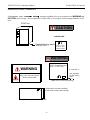
OPERATING SAFETY WARNINGS
In this <$61$&3&1&&RQQHFWLQJ0DQXDO warnings regarding safe use are categorized as WARNING and
CAUTION (refer to Page 1 for an explanation of these terms). An example of this warning method is as follows:
PCNC Unit
CAUTION
WARNING LABEL
Read all Warning label’s
of PCNC Unit.
BE SURE TO CONNECT
GROUNDING LINE TO
GROUNDING TERMINAL
WARNING
PCNC Opeartion panel
with 14” CRT Unit
WARNING
14 “ CRT UNIT or
LCD ( Expected)
rear side warning
Label
May cause electrical shock.
Do not touch inside.
(Make sure to connect grounding )
( Make sure to connect grounding )
Read all the cautions and warnings
24 DC Power supply unit ( UPS 000004 )
xi
YASNAC PCNC Connecting Manual
Preface/Table of Contents
TRANSPORT PRECAUTONS
CAUTION
•
When moving the product, do not lift by the cable.
•
Once the product has been installed on the machine and the eyebolts have been removed, insert
suitable size machine bolts in the mounting holes.
•
The product should not be exposed to harmful environmental conditions, i.e., water, harmful
gases or liquids.
Failure to observe these precautions may result in personal injury or product damage.
STORAGE
CAUTION
•
This product should not be exxposed to harmful environmental conditions, i.e, water, harmful
gases or liquids.
•
Product should be stored in a clean indoor area that meets the following temperature and humidity
conditions:
• Ambient temperature: -15oC to 65oC (-5oF to 149oF)
• Relative humidity
: 10% to 90%
• Altitude
: 1000 m or less ( 10000ft or less )
Failure to observe these precautions may result in personal injury or product damage.
xii
YASNAC PCNC Connecting Manual
Preface/Table of Contents
INSTALLATION
CAUTION
•
Install peripheral equipment in accordance with the following:
1. A rust preventative substance has been applied to the motor shaft’s end and flange. Remove
the substance using a clean cloth.
2. When connecting the motor shaft to a driven machine, be sure to center-align accurately to
prevent vibration.
3. Mount the servo unit(Converter,Inverter and Amplifier ) vertcally and fasten firmly in place
with screws or bolts.
4. Since the servo unit (Converter,Inverter and Amplifier ) will generate heat, install the unit with
sufficient clearance for cooling air flow.
5. In order to reduce heat generation, position the servo unit’s(Converter,Inverter and Amplifier)
cooling fan outside of the enclosure for exposure to the external atmosphere for cooling.
6. When circulating air inside of the enclosure, do not blow air directly onto the servo unit since
dust contamination could occur.
7. Position and mount components so that they are easily accessible for inspection and maintenance.
Failure to observe these precautions may result in product failure.
CAUTION
•
When installing this product, do not close the intake or exhaust ports, but take precautions to
prevent foreign matter from entering this device
•
Do not subject this product to any strong physical impacts.
•
Set the power line capacity higher than this product’s power consumption level.
Failure to observe these precautions may result in personal injury or product damage.
xiii
YASNAC PCNC Connecting Manual
Preface/Table of Contents
WIRING
CAUTION
•
Use the shortest wires when making connections.This helps prevent malfunction.
•
Connect the +24V DC power supply to the PC NC unit.
1. The power supply should be provided at the customer’s site.
(The power supply unit, UPS000004, is available as an option.)
2. Supply the power in the range of +24V DC +10% to the PC NC unit’s inlet (CN05).
•
Do not run the I/O signal wires with power wires or in the same duct. Ample separation of signal
wires from power wires will reduce the noise influence.
•
If noise occurs, use a noise suppressor to eliminate it. Refer to the section in this connection
manual for noise filter specifications and capacities.Use of the correct noise filter will reduce
noise influence.
•
Be sure to complete the end-terminal-processing to the last module of the remote I/O module.
Set the “TERMINATION” shorting pin to “ON”.
Failure to follow these instructions could result in malfunction.
CAUTION
•
Electrical wiring and connections should be performed by qualified personnel only.
Failure to observe this precaution could result in product failure, fire and/ or
personal injury or death due to electrical shock.
•
Never connect a three-phase power supply to motor output terminals, U,V or W of the drive unit.
Damage to the device will occur if incorrectly connected.
•
Select the type and size of wire based on your requirements and current capacity. When the
ambient temperature exceeds 30oC (86oF), the allowable current drops. Select the cable size to
conform to the local electrical codes and cable manufacturer’s specifications.
Failure to comply could result in an electrical fire.
•
Use twisted wire or multi-core twisted pair shielded wire for general signal wires and feedback
signal wires for the encoder.
These wire types help prevent malfunction.
xiv
YASNAC PCNC Connecting Manual
Preface/Table of Contents
CAUTION
•
The current capacity of 24V DC (external power unit for input/output contacts) is determined by
the number of contact points to be used. When the current capacity is low, install an additional
external power unit.
•
An enclosure for this product should be designed and constructed to meet the following:
1. Use an airtight enclosure.
2. Limit the average temperature rise of air within the enclosure to less than 10oC (50oF)
compared to the ambient temperature.
3. Use a UL approved fan to circuate the air in a closed enclosure to improve cooling efficiency,
and to prevent abnormal heat rise.
4. Seal the cable inlet, door, etc. completely.
5. Since a CRT display attracts airborne particles due to its high voltage that could result in
malfunction, therefore, provide an enclosure capable of preventing dust from entering the CPU.
6. Ambient magnetic field may cause CRT screen fluctuations, therefore, prevent this with a
layout and magentism shield.
7.In PC NC Unit,printed circuit boards,various units may accumlate dust from air,may result in
malfunction,therfore ,make structures to prevent the entry of dust.
8.Install packing on the cable inlet,doors,back covers,etc. to eliminate gaps or openings.
Failure to observe these precautions may result in product failure.
xv
YASNAC PCNC Connecting Manual
Preface/Table of Contents
CAUTION
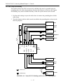
•
Connect each unit’s grounding line individually to the housing or grounding plate.
See the following example:
.
200VAC
LF
S, V
.
U
V
. .
W
M
E
CN
CN
E
External
Box
F, B
Operation relay
sequence
LF
AVR
Grounding at one
point (100Ω / less)
•
Select the wire for grounding in conformance with local electrical codes.
•
Be sure to connect the motor’s grounding terminal to the drive unit’s grounding terminal.
•
Ground at one point. (Ground resistance 100Ω or less).
•
Be sure to seperate the grounding line of the unit from the power unit’s grounding line.
Failure to perform correct grounding can lead to malfunction.
xvi
YASNAC PCNC Connecting Manual
Preface/Table of Contents
APPLICATION SAFETY PRECAUTIONS
CAUTION
•
When operating the unit, be sure to observe the following electrical safety procedures
1.Do not touch the unit or terminal wire while the unit is operating.
2. Even though the unit has been turned OFF, it is still in charged status, so do not touch any
component parts for a minimum of five minutes.
Failure to observe this precaution could result in product failure, fire and/ or personal injury
or death due to electrical shock.
•
Do not mishandle, pinch or cause excessive stress to cables.
Excessive load on the cable could cause electric shock.
•
While the unit is turned ON, never touch any rotating parts.
Failure to observe this precaution could result in personal injury.
Never modify the product
Free from explosive gases or steam
Free from oil,organic solvent,corrosive liquids etc.
Vibration under (0.5 G).
Never disassmble or modify the components of the unit.
Never change the set values of the components and any variable resistors used in control panel.
Failure to observe this warning could result product failure, fire and/ or personal injury
or death due to electrical shock.
xvii
YASNAC PCNC Connecting ManualChapter 1: General
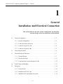
1
General
Installation And Electrical Connection
This section addresses the basic system: configuration, specifications,
enclosure design, electrical connections and installation.
1.1
System Configuration . . . . . . . . . . . . . . . . . . . . . . . . . . . . . . . . . . . . . . . . . . . . . . .1 - 2
1.1.1
System Configuration . . . . . . . . . . . . . . . . . . . . . . . . . . . . . . . . . . . . . . . . .1 - 2
1.1.2
Connection between Devices . . . . . . . . . . . . . . . . . . . . . . . . . . . . . . . . . . .1 - 3
1.1.3
Connector Layout NC side . . . . . . . . . . . . . . . . . . . . . . . . . . . . . . . . . . . . .1 - 4
1.1.4
Connector Layout PC side . . . . . . . . . . . . . . . . . . . . . . . . . . . . . . . . . . . . .1 - 5
1.2
General Specifications . . . . . . . . . . . . . . . . . . . . . . . . . . . . . . . . . . . . . . . . . . . . . .1 - 6
1.3
Thermal Design of Enclosure . . . . . . . . . . . . . . . . . . . . . . . . . . . . . . . . . . . . . . . . .1 - 7
1.3.1
Thermal Design. . . . . . . . . . . . . . . . . . . . . . . . . . . . . . . . . . . . . . . . . . . . . .1 - 7
1.3.2
Dust Proof Design. . . . . . . . . . . . . . . . . . . . . . . . . . . . . . . . . . . . . . . . . . . .1 - 11
1.3.3
Countermeasure Against Magnetic Fields . . . . . . . . . . . . . . . . . . . . . . . . .1 - 12
1.4
Cable Clamp and Shielding . . . . . . . . . . . . . . . . . . . . . . . . . . . . . . . . . . . . . . . . . .1 - 13
1.5
Packaging . . . . . . . . . . . . . . . . . . . . . . . . . . . . . . . . . . . . . . . . . . . . . . . . . . . . . . . .1 - 14
1.5.1
General Notes . . . . . . . . . . . . . . . . . . . . . . . . . . . . . . . . . . . . . . . . . . . . . . .1 - 14
1.5.2
Installation of PCNC Unit. . . . . . . . . . . . . . . . . . . . . . . . . . . . . . . . . . . . . .1 - 15
1.5.3
Installation of Feed/Spindle Servopacks. . . . . . . . . . . . . . . . . . . . . . . . . . .1 - 16
1-1
YASNAC PCNC Connecting ManualChapter 1: General
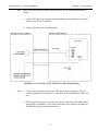
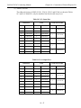
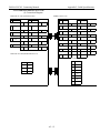
1.1 System Configuration
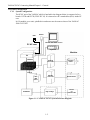
1.1.1
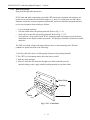
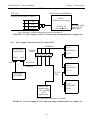
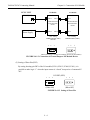
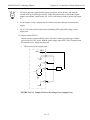
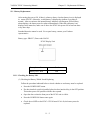
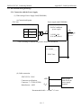
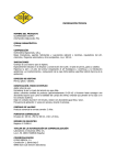
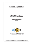
System Configuration
The PCNC unit of the YASNAC which is hatched in the diagram below is composed of two
boards: JCP20 and JFC20 (JZNC-JFC10). It is inserted to a PC extended bus (ISA) inside PC
case.
Its I/O module, servo unit, spindle drive and motor are the same as those of the YASNAC
J100 CNC UNIT.
FDD
Mouse
Monitor with Touch screen
PC NC case
Keyboard
Machine
PC
ISA bus
Feeding
servo unit
Feeding
motor
JFC10
DC
+24V
power
I/O Module
Spindle
drive unit
Spindle motor
High voltage
Device
on
machine side
Figure 1.1.1 YASNAC PCNC System Structure Diagram
1-2
YASNAC PCNC Connecting ManualChapter 1: General
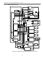
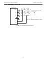
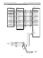
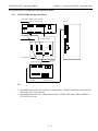
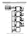
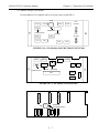
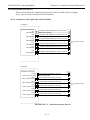
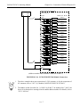
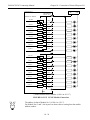
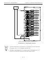
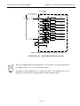
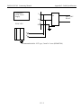
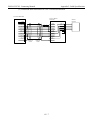
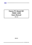
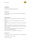
1.1.2
Connection Between Devices
C P U R A C K U N IT
CRT
KEYBO AR D
DA TA
HDD
ATX
MOTHER
BO ARD
M O U SE
PW R
TB3
FDD
DA TA
PWR
ID E I/F
KBD
TS
CONTROL
COM2
TOUCH
SC R EEN
FDD
SE RVO ON
COM1
SH UT D OW N
P S /2 M O U S E
LP T 1
DC
OUT
2 4V D C F O R
M A C H IN E I/O
V ID E O
CARD
V ID E O
M A C H IN E O P . P A N E L I/O
C N1~6
P CI
JF C 20
M A C H IN E
C ONTROL
S IG N A LS
I/O B O A R D C N 14
F O R M A C H IN E S IG N A L
(F C 8X X )
C N11
C N5
C N13
C N3
C N 12
I/O B O A R D C N 1
F O R M A C H IN E
O P. PNL.
(J S P 0 2 /0 4)
HPG
C N 7,8,9
M A C H IN E P A N E L
S IG N A LS
C N 01
S E N S O R S IG N A L
C N 02
S E R V O U N IT
C N 03
C N 04
IS A
4C N
S G D C -* *A J A
SG M G **A 2A B *
3C N
M
2C N
PG
3C N
M
2C N
PG
3C N
M
2C N
PG
C N 05
1C N
Z A X IS
5 2C N
5 1C N
4C N
FA N1
S G D C -* *A J A
1C N
JC P 20 -1
C N 11
Y A X IS
5 2C N
C N 12
5 1C N
C N 13
CPU
FAN
C N 14
4C N
S G D C -* *A J A
1C N
5 2C N
X A X IS
5 1C N
FAN 3
CASE FA N
IN V E R T E R U N IT
U A A S K *-**F Z *
C 1M R -M 5N
M
4C N
PC PO W ER
SU P PLY OUT
O UT
1C N
5 2C N
PG S
(P O W E R
GOOD
S IG N A L )
IN P U T
2C N
PG
5 1C N
C O N V E R T E R U N IT
C 1 M R -M R 5N
N C PO W ER
SU PPLY
IN P U T
5C N
R /S /T
REACTO R
X 0 10 0 **
A 1 /A 2
O U TPU T
IN P U T P O W E R U N IT
TB2
SVM
TB1
NFB
SVM
A C 2 30 V
A 1/A 2
Figure 1.1.2.1 Detail Connection of PCNC Unit with various devices.
1-3
FA
N
YASNAC PCNC Connecting ManualChapter 1: General
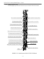
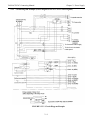
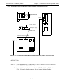
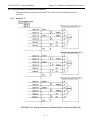
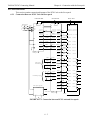
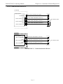
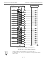
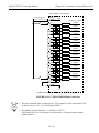
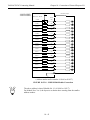
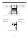
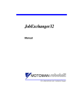
1.1.3
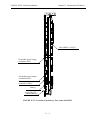
Connector Layout NC Side
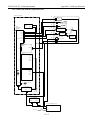
The following figure gives the detail Connectors Layout of YASNAC JZNC-JFC10 board.
Servo controller connector (CN01)
Servo controller I/O connector (CN11)
I/O module connector (CN02)
Power On/Off connector (CN12)
Power good signal connector (CN03)
Fuse (HM03, 0.3A) (F1)
Interruption setting short pin (S11)
RS232C connector (CN14)
Memory address setting rotary switch (S12)
I/O module power output verification LED
Direct IN/OUT connector (CN14)
I/O module power output connector (CN04)
System load switch (S1)
I/O module power input connector (CN05)
System load switch (S1)
(from top: 1, 2, 3, 4)
I/O module power input verification LED
Battery alarm LED
Battery power reply supply connector (CN06)
System load rotary switch (S1)
Battery
FIGURE 1.1.3.1: Details Layout of YASNAC JZNC-JFC10 Board
1-4
YASNAC PCNC Connecting ManualChapter 1: General
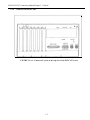
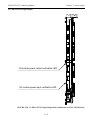
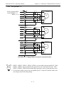
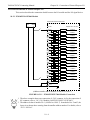
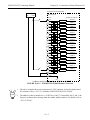
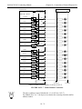
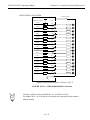
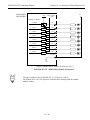
1.1.4
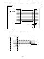
Connector Layout PC Side
FIGURE 1.1.4.1: Connector Layout on the top view of the PCNC CPU rack
1-5
YASNAC PCNC Connecting ManualChapter 1: General
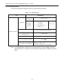
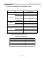
1.2 General Specifications
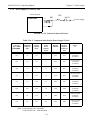
The enclosure should be designed to meet all of the following conditions.
Table 1.2.1: Specifications
Item
Specifications
Storage and
Transportation
Temperature*
Operating
(around
enclosure)
Humidity
-15oC to +65oC
PCNC unit
I/O module
Servopack
14” Color monitor with
touch screen
0oC to +53oC
20% to 80% RH (with operation)
10% to 90% RH (with non-operation)
Ambient Conditions
Vibration
during operation
Less than 4.9m/s
Others
Free from dust, coolant or organic solvent
PCNC Unit input power supply
+24VDC+10%
180V-264V AC
Power Supply Unit UPS000004
• Input power supply voltage: 180V-264VAC
• Frequency: 47 Hz to 63 Hz
• Momentary interruption: 0.5 cycle (0 VDC)
Note: Avoid installing the control panel in a location subject to direct sunlight, near heat
generating devices or outdoors even if the ambient temperature is within the specified
range.
1-6
YASNAC PCNC Connecting ManualChapter 1: General
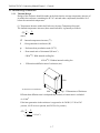
1.3 Thermal Design of Enclosure
1.3.1
Thermal Design
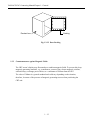
Design of the enclosure should be made on the basis that the average temperature increase of
air within the enclosure (containing the PC NC unit and other components) should be 10oC
below the external air temperature.
(1) Temperature Increase within the Enclosure (Average Temperature Increase)
The internal temperature increase (sheet metal enclosure) is generally as follows:
∆Τ= P = .P
qe k A
where,
∆Τ : Internal temperature increase (oC)
P
: Heat generation in enclosure (W)
qe
: Enclosure heat percolation ratio (W/oC)
k
: Heat transit ratio of sheetmetal (W/m2oC)
6W/m2oC: With internal cooling fan
4W/m2oC: Without internal cooling fan
A
: Efficient heat diffusion area of enclosure (m2)
1200
All dimensions in millimeters
Fig 1.5 Dimensions of Enclosure
700
Efficient heat diffusion area is independently located, so bottom area is excluded.
800
A=4.16m2.
If the heat generation in the enclosure is supposed to be 246W (113 W in CNC
portion, 104 W in servo portion, and 29 W in I/o portion),
P
∆Τ= qe = kP
.A
= 246 = 9.9 (oC)
6 x 4.16
1-7
YASNAC PCNC Connecting ManualChapter 1: General
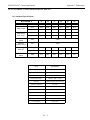
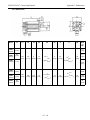
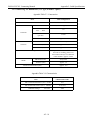
(2) Heat Exchanger Cooling Capacity
Where cooling capacity is insufficient even with a circulating fan mounted in the
enclosure, Yaskawa can provide heat exchangers.
Table 1.3.1.1: Heat Exchangers
Heat Exchanger
Cooling Capacity
External Dimensions (mm)
REX1550
100W /10oC
295 width x 890 height x 50 depth
HEATEX02
250W /10oC
440 width x 924 height x 50 depth
The heat generation indicated in the above table is the allowable heat generated when the
internal temperature increase in the enclosure is limited to under 10oC.
Example: Allowable Heat Generated in the Enclosure with Heat Exchanger
The amount of internal heat generated to make the internal temperature under 10oC when
the enclosure is equipped with a HEATEX02 Heat Exchanger is expressed by the
following equation:
.....................................................
P= k.A.∆Τ+ 250 W/10oC
= 6 x 4.16 x 10 + 250
= 499 W/10oC
therefore, it is necessary to be under 499W.
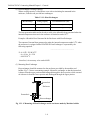
(3) Mounting Heat Exchanger
Heat exchanger should be mounted on the enclosure provided by the machine tool
builder. Fig. 1.5 shows a mounting example. Mount the exchanger so that the internal air
is drawn from the upper portion and discharged through the lower portion, while external
air is drawn in from the lower portion and discharged through the upper portion.
Internal air
Enclosure
External air
Heat exchanger
Fig 1.3.1.1: Mounting of Heat Exchanger on the enclosure made by Machine builder
1-8
YASNAC PCNC Connecting ManualChapter 1: General
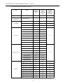
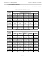
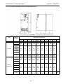
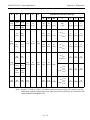
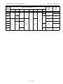
(4)Heat Generation by Respective Units
Unit
Type
PCNC rack
JZNC-JPCRKM_-_
14” Color CRT with
Touchscreen
JZNC-JPCOP-_ _ _
I/O Module
Total Heat
Generation
(W)
Internal
Heat
Generation
(W)
Minimum
Wind
Velocity for
Cooling
JANCD-FC810*
29
29
0
JANCD-FC860*
29
29
0
JANCD-FC861*
14.5
14.5
0
CIMR-MR5N23P7
84
44
CIMR-MR5N25P5
84
44
CIMR-MR5N27P5
119
61
CIMR-MR5N2011
152
70
CIMR-MR5N2015
204
88
CIMR-MR5N2018
273
108
CIMR-MR5N2022
335
132
CIMR-MR5N2030
392
160
CIMR-MR5N23P7
84
44
CIMR-MR5N25P5
185
58
CIMR-MR5N27P5
244
77
CIMR-MR5N2011
307
89
CIMR-MR5N2015
454
119
CIMR-MR5N2018
565
144
CIMR-MR5N2022
717
180
CIMR-MR5N2030
869
219
UZBA-B 20A 0.53 mH
35
35
0
UZBA-B 30A 0.35 mH
45
45
0
UZBA-B 40A 0.265 mH
50
50
0
UZBA-B 60A 0.18 mH
65
65
0
UZBA-B 80A 0.13 mH
75
75
0
UZBA-B 90A 0.12 mH
90
90
0
UZBA-B 120A 0.09 mH
90
90
0
UZBA-B 160A 0.07 mH
100
100
0
Converter
2.5
Spindle Inverter
2.5
Reactor
1-9
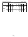
YASNAC PCNC Connecting ManualChapter 1: General
Unit
Type
Total Heat
Generation
(W)
Internal
Heat
Generation
(W)
SGDC-05AJ A
28
10
SGDC-10AJ A
48
12
SGDC-15AJ A
73
15
SGDC-20AJ A
108
18
SGDC-30AJ A
148
22
SGDC-50AJ A
208
28
Servo Unit
POINT
Minimum
Wind
Velocity for
Cooling
2.5
1. The heat generated by the CNC unit varies depending on the addition
of options. The heat generated by the I/O module varies with I/O
status.
2. Internal heat generation is the heat remaining inside of the enclosure
when the servo unit’s fin is exposed outside of the enclosure, and
when the external air is applied to the fin at greater than 2.5m/s
3. Thermal design of the enclosure to house the servo unit varies with
machine specifications, but is acknowledged to use a value of 70% of
the load factor.
1 - 10
YASNAC PCNC Connecting ManualChapter 1: General
1.3.2
Dust proof Design
Dust proof Design and Construction
PCNC units and other components (especially CRTs) housed in a machine tool enclosure are
exposed to an environment with airborne matter, e.g., dust. oil, coolant mist, etc.Since these
elements could cause control component malfunction, enclosures should be designed and built
to prevent such matter from entering as follows:
•
•
•
•
Use an air-tight enclosure.
Seal the cabinet inlet with packing material. Refer to Fig. 1.3.2.1.
Secure the rear door lid with packing material. Refer to Fig, 1.3.2.2.
The enclosure’s front surfaces with PCNC operating panels and are dust proof, but do not
install them where liquid coolants are present. The periphery should be sealed with suitable
materials.
The CRT unit’s high voltage will attract airborne dust, so when mounting the CRT unit’s
pendant box please take note of the following:
1. Seal the cable inlet, door, rear lid opening clearances with packing material.
2. The CRT Unit’s mounting surface has been factory sealed.
3. Seal any other openings.
4. Since oil will enter the enclosure through screw holes and collect on the
internal ceiling surface, apply suitable packing material to seal these holes.
Metal fitting
Packing
Cable
Fig. 1.3.2.1 Cable Inlet
1 - 11
YASNAC PCNC Connecting ManualChapter 1: General
Pendant box
Packing
Fig. 1.3.2.2 Door Packing
1.3.3
Countermeasures against Magnetic Fields
The CRT screen’s display may fluctuate due to ambient magnetic fields. To prevent this, keep
magnetic generating materials, e.g., transformers, reactors, fans, electro-magnetic switches,
solenoid relays, exchange power cables, etc. a minimum of 300mm from the CRT.
The value of 300mm is a general standard and could vary depending on the situation,
therefore, be aware of the presence of magnetic generating sources when positioning the
CRT unit.
1 - 12
YASNAC PCNC Connecting ManualChapter 1: General
1.4 Cable Clamp and Shielding
If the cables wired to the PCNC unit need to be shielded, they must be grounded using the
grounding plate with cable clamp hardware. Because this clamp serves both as cable support
and shielding, they must be installed carefully so that safe system motion can be assured.
1. Peel the cable coating to expose the cable where it connects the grounding plate with the
cable clamp.
CD-ROM
ZIP
2. The cable clamps (with the cables) must be installed to the grounding plate as shown in the
following diagram:
VGA
CRT
POWER
DATA
Touch
Panel
POWER
DATA
FDD
2m max.
Keyboard
SERIAL
CARD
(OPTION)
CPU
RACK
IPU
PS/2
Drive IO
FDD
YENET D
COM1
YENET IO
EX.DC
24VDC
VGA
PARALLEL
Mouse
IPU
Drive IO
YENET
YENET
24VDC
Drive
Pack
IO
Ferrite Core
YENET
Shield Clamp
Last IO
24VDC
FIGURE 1.4.1: Yasnac PCNC Shielding and Ferrite core clamping points
1 - 13
YASNAC PCNC Connecting ManualChapter 1: General
1.5 Packaging
When designing the enclosure to house the CNC unit and other equipment, the construction
should provide for the following:
1.5.1
General Notes:
•
The enclosure must be air-tight.
•
Internal layout of components should provide for ease of mounting, inspection maintenance,
and removal.
•
There should be a physical gap of 100mm between components and the enclosure’s wall so
not to restrict air flow for cooling.
•
If the operation panel is built into the machine’s enclosure door, provisions to prevent vibration from the machine is necessary.
•
The average temperature increase in the enclosure should be limited to 10oC compared to the
external air.
•
Use a fan to circulate air to improve cooling efficiency within the enclosure. As a general rule,
the fan should blow air upward at 1m/s over the p.c. board’s surface.
•
The fan should not blow air directly onto the p.c.board.
•
To prevent malfunctions due to noises, keep noise generating elements 10m away from AC
power supply cables and components (over 90VDC).
•
When wiring, separate AC from DC lines, and separate primary side from the transformers’s
secondary side, line filter, etc.
1 - 14
YASNAC PCNC Connecting ManualChapter 1: General
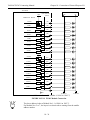
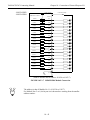
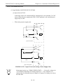
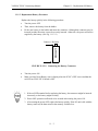
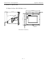
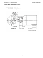
1.5.2
Installing the PCNC Unit
•
•
The PCNC unit has a built-in fan that blows air (1 m/s) over the upper side of the PCNC unit.
Provide clearances of 50 mm minimum above the 100 mm minimum below the PCNC unit for
ventilation and maintenance.
10.16 [0.40]
DETAIL 1
R2.54 [0.10]
F1
CN03 (PGS)
CN12 (IPU)
CN0 2 (RIO)
CN11 (DRV I/O)
CN01 (SV/SP)
JZNC - JFC10
BATTERY
SW3
BAT 4
3 2
1
CN06 (BAT)
CN05
+2 4V (IN +24V)
SW1
CN14 (DIN)
CN0 4
(OUT +5V/+24V) +5V
CN13 (COM PLC)
R6.35 [0.25]
FIGURE 1.5.2.1: Mounting of PCNC Unit
1 - 15
YASNAC PCNC Connecting ManualChapter 1: General
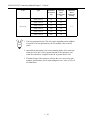
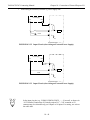
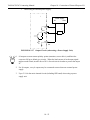
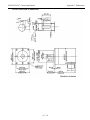
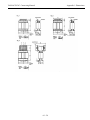
1.5.3
Installing the Feed/Spindle Servopacks (Amplifiers)
•
The Servopack is to be wall-mounted vertically using screws or bolts.
•
Locate the Servopack so that inspection, maintenance and part replacement can be easily
made.
•
The Servopack will generate some heat, so mount with sufficient space around the unit.
•
To reduce heat generation, mount the cooling fin external to the Servopack’s enclosure with
the fan blowing air on the cooling fin @ 2.5m/s.
•
Internal air should not be blown directly onto the Servopack since this could cause dust contamination.
Cooling fin
Feed Servopack
Converter & Inverter
External Air
Fig. 1.5.3.1 Cooling Fin Installed Outside of Enclosure
1 - 16
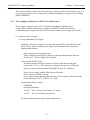
YASNAC PCNC Connecting Manual
Chapter 2: Power Supply
2
Power Supply Connection
Connecting Power Supply To Components.This section addresses the following electrical
connections: power supply to components, detailed connections and LED connections.
2.1
2.2
2.3
Connection between Devices . . . . . . . . . . . . . . . . . . . . . . . . . . . . . . . . . . . . . . . . .2 - 2
2.1.1
Power Supply specifications for PCNC and I/O units . . . . . . . . . . . . . . . .2 - 2
2.1.2
Power Supply connections to PCNC . . . . . . . . . . . . . . . . . . . . . . . . . . . . .2 - 3
2.1.3
Power Supply Connections to PCNC and I/O units . . . . . . . . . . . . . . . . . .2 - 3
2.1.4
Power Supply to Converter unit . . . . . . . . . . . . . . . . . . . . . . . . . . . . . . . . .2 - 4
Detailed Connections . . . . . . . . . . . . . . . . . . . . . . . . . . . . . . . . . . . . . . . . . . . . . . .2 - 5
2.2.1
Power Supply to PCNC unit . . . . . . . . . . . . . . . . . . . . . . . . . . . . . . . . . . . .2 - 5
2.2.2
Power Supply to Converter. . . . . . . . . . . . . . . . . . . . . . . . . . . . . . . . . . . . .2 - 7
2.2.3
Example of Circuit Diagram . . . . . . . . . . . . . . . . . . . . . . . . . . . . . . . . . . .2 - 8
LED for Power Input /Output . . . . . . . . . . . . . . . . . . . . . . . . . . . . . . . . . . . . . . . . .2 - 9
2.3.1
LED for PCNC Power Input . . . . . . . . . . . . . . . . . . . . . . . . . . . . . . . . . . . .2 - 10
2-1
YASNAC PCNC Connecting Manual
Chapter 2: Power Supply
2.1 Connection between Devices
This section describes connections between devices, connector numbers and connector type. For
power supply connection use a commercially available standard power supply or Power Supply
Model UPS000004.
2.1.1
Power Supply specifications for PCNC Unit and I/O units.
Power supply connection to the PCNC unit differs depending on whether using a
commercially available standard power supply for both PCNC and I/O units or use a
recommended power supply unit only for PCNC and use another power supply for I/O units.
(1) Selection of Power Supply
(a) Using a Standard Power Supply
Excluding +24V power supply for I/O input and output,90W is required for the total
PCNC system. Select a suitable power supply with consideration for temperature
derating characteristics.
•
Power supply for I/O input and output
Select a suitable power supply by referring to the calculation example shown in
Section 10.3.3 “Power Supply for I/O Signal”.
•Power supply for PCNC Unit
In order to provide 90W power capacity or greater when the internal panel
temperature is 55oC, a +24V output power supply with capacity of 150W and
greater is required: (Recommended UPS000004 is rated for 150 Watts.)
Select a power supply with the following specifications:
Power capacity of 150W or greater.
Power supply with the derating characteristics of 60% or greater when the internal
panel temperature is 55oC. (150W x .06 = 90W)
•Recommended Power Supply:
UPS000004
Operating Conditions:
At 50oC - 100% ( Out put rated Current 6.5 Amps)
At 55oC - 80 % ( Derated Output Current )
For more details contact the power supply manufacturer.
2-2
YASNAC PCNC Connecting Manual
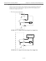
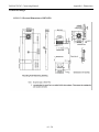
2.1.2
Chapter 2: Power Supply
Power Supply Connections to PCNC
CNC unit
Power supply unit(UPS00004)
JANCD-JFC10 CN05(1-178293-2)
1
+24V
2
024V
3
FANALM
+24VDC
Stabilized power supply
+24VDC+10%
3.0 A min. (Note*)
AC Power Supply
180V-264V AC
Single phase
*Note: Derating for ambient temperature should be considered.
FIGURE 2.1.2.1 Power Supply to PCNC Unit when using recommended Power Supply Unit.
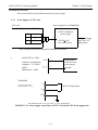
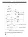
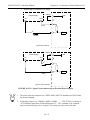
2.1.3
Power Supply Connections to PCNC and I/O Units
UWR00306
PCNC UNIT
JANCD-JIF10
CN05
* Terminal
Block
CN04
+24VDC
CN 13
JANCD-FC8_ _
CN 14
24V
5V
UWR00305
5V DC & GND
CN 13
JANCD-FC8_ _
UWR00307
CN 14
24V DC
GND
+24V supply
(UPS00004)
Machine Tool
Builder supply
+24V according
to I/O
requirements.
CN 05
JSP04/JSP02
CN 06
* To be provided by Machine Tool builder
FIGURE 2.1.3.1 Power Supply to PCNC unit when using recommended Power Supply Unit
2-3
YASNAC PCNC Connecting Manual
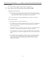
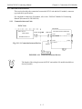
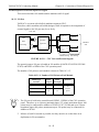
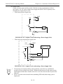
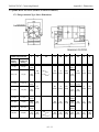
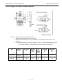
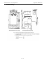
2.1.4
Chapter 2: Power Supply
Power Supply to Converter Unit
Converter unit
CIMR-MR5
L
TXR
MC
MCCB
Power supply
FIGURE 2.1.4.2 Connection between Devices
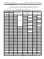
Table 2.1.4.2 Component Selection for Power Supply Circuit
Reator*
1L
Converter
Type CIMRMR5N2
Applicable
Capacity
(kW)
Output
Capacity
(kW)
Power
Source
Capacity
(KVA)
Breaker
1MCCB
Electromagnetic
Contactor
1MC
3P7
3.7
4.6
7
30A
20A
20 A 0.53 mH
(x 002491)
(x 010057)
5P5
5.5
6.8
9
40A
30A
30 A 0.35 mH
(x 002492)
(x 010058)
7P5
7.5
9.3
12
50A
40A
40 A 0.265 mH
(x 002493)
(x 010059)
011
11
13.6
19
75A
60A
60 A 0.18 mH
(x 002495)
(x 010060)
015
15
18.6
24
100A
75A
80 A 0.13 mH
(x 002497)
(x 010061)
018
18.5
22.9
30
125A
100A
90 A 0.12 mH
(x 002498)
(x 010062)
022
22
27.2
36
150A
125A
120 A 0.09 mH
(x 002555)
(x 010063)
030
30
37.1
48
175A
150A
160 A 0.07 mH
(x 002556)
(x 010064)
ooo
*Note: Code in upper row: with leads
Code in lower row : with terminals
2-4
YASNAC PCNC Connecting Manual
Chapter 2: Power Supply
2.2 Detailed Connection
This section describes the detailed connection of power supply.
2.2.1
Power Supply to PCNC unit
CNC unit
Power Supply Unit (UPS000004)
JANCD-JFC10 CN05(1-178293-2)
1
+24V
2
024V
3
+24VDC Stabilized
power supply
+24VDC+10%
3.0 A min. (Note*)
FANALM
ó
AC Power Supply
180V-264V AC
Single phase
*Note: Derating for ambient temperature should be considered.
JANCD-JFC10 CN05
+24V
Connector specifications
Connector : 1-178288-3
(3PIN)
Manufacturer : AMP
024V
1
2
Select proper
cable fit for the
power supply
terminal.
UPS000004
Connector specification
Criimp terminal : 1.25 -4
L
200 VAC Single-phase
N
FG
Recommended cable : VCT type, 2mm2 x 5 cores (DE8402398)
FIGURE 2.2.1.1 Power supply connections to PCNC Unit and 24V DC Power supply unit.
2-5
YASNAC PCNC Connecting Manual
ó
UPS000004
24 DC Power
Supply
Chapter 2: Power Supply
L
LF
180V~264V
1Ph AC
N
PCNC CPU
FG
L
N
LF - Line Filter. Use line filter. For selection of Line filter
refer Appendix-1.
Note: Use 3.5mm sq or more for the Frame ground wire
FIGURE 2.2.1.2 Power supply connections to PCNC Unit and 24V DC Power supply
PCNC Power Socket and Frame ground details
10.16 [0.40]
DETAIL 1
R2.54 [0.10]
F1
CN03 (PGS)
CN12 (IPU)
CN02 (RIO)
CN11 (DRV I/O)
CN01 (SV/SP)
JZNC - JFC10
BATTERY
SW3
BAT 4
3 2
1
CN06 (BAT)
CN05
+24V (IN +24V)
SW1
CN14 (DIN)
CN04
(OUT +5V/+24 V) +5V
CN13 (COM PLC)
R6.35 [0.25]
FIGURE 2.2.1.3 PCNC unit frame ground wire to be connected
2-6
YASNAC PCNC Connecting Manual
Chapter 2: Power Supply
Note: Please follow the Frame Ground connection details for the machine and electrical
cabinet.
1. Connect FG Cable from customers main grounding point to Machine’s electrical
cabinet where PCNC is mounted.
2. Connect FG cable from customers mains
FIGURE 2.2.1.4 YASNAC PCNC CRT Power and Ground Wiring
Note: 1. Connect CRT ground wire only to the CRT chassis ground terminal. Do NOT
connect ground wire to terminal “E” on the main power terminal block of the CRT
unit.
2. CRT Ground wire must be a separate wire directly connected to the main cabinet
ground plate or ground bar. Any other connections to the machine operation box
should be done using separate ground wires.
2-7
YASNAC PCNC Connecting Manual
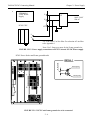
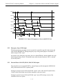
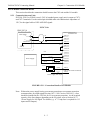
2.2.2
Chapter 2: Power Supply
Power Supply to Converter Unit
Converter unit
CIMR-MR5
R/L1
1L
.
MC
TXR
MC
S/L2
R
TXR
MCCB
1L
200/220/230 VAC-15% to 10%
50/60 Hz +2Hz
S
MC
.
TXR
1L
T/L3
A1
MCCB
MCCB
T
Fig. 2.2.2.1 Detailed Connection of Power
r
t
A2
FIGURE 2.2.2.1 Detailed Connection of Power
2-8
YASNAC PCNC Connecting Manual
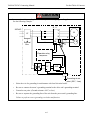
2.2.3
Chapter 2: Power Supply
Circuit Diagram Example (Power magnets & PCNC CN12 Control Signals)
To Customer PWR supply
To fan for air circulation
inside panel
CN12 (IPU)
FIGURE 2.2.3.2 Circuit Diagram Example
2-9
YASNAC PCNC Connecting Manual
Chapter 2: Power Supply
2.3 LED for Power Input/Output
I/O module power output verification LED
I/O module power input verification LED
FIGURE 2.3.0.1 LED for PCNC Input/Output Power Indication on JCNC-JFC10 Board
2 - 10
YASNAC PCNC Connecting Manual
2.3.0
Chapter 2: Power Supply
LED for PCNC Power input
The status of +24V power supply to the CNC unit can be confirmed by the LED.
The LED is lit when +24V power is supplied properly.
When +24V power is not supplied or when the fuse inside the PCNC unit is blown out due to a
fault of PCNC unit, the LED will be unlit.
2 - 11
YASNAC PCNC Connecting Manual
Chapter 3: Connection of PCNC Operation Panel
3
Connection of PCNC Operation Panel
CONNECTING PCNC OPERATOR PANEL AND PCNC
This section addresses the electrical connection between the PCNC unit
and the CNC Operator panel.
3.1
Connection between Devices . . . . . . . . . . . . . . . . . . . . . . . . . . . . . . . . . . . . . . . . . . 3 - 2
3.1.1
3.2
Detailed Connection of PCNC Operation panel . . . . . . . . . . . . . . . . . . . . . . . . . . . . 3 - 3
3.2.1
3.3
Connection with the Operation panel . . . . . . . . . . . . . . . . . . . . . . . . . . . . . . 3 - 2
Connection with Operation panel . . . . . . . . . . . . . . . . . . . . . . . . . . . . . . . . . 3 - 3
General notes on Connection with operation Panel . . . . . . . . . . . . . . . . . . . . . . . . . 3 - 8
3.3.1
JANCD-JSPO4/JANCD-J861 . . . . . . . . . . . . . . . . . . . . . . . . . . . . . . . . . . . 3 - 8
3.3.2
PCNC Connections Layout. . . . . . . . . . . . . . . . . . . . . . . . . . . . . . . . . . . . . . 3 - 9
3.3.3
Extended I/O board FC861 and Remote Machine Pendant connections . . . 3 - 10
3-1
YASNAC PCNC Connecting Manual
Chapter 3: Connection of PCNC Operation Panel
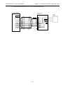
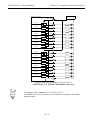
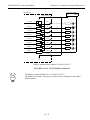
3.1 Connection Between Devices
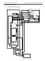
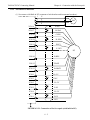
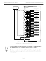
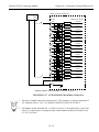
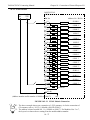
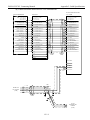
3.1.1
Connection with Operation Panel
C P U R A C K U N IT
(a)
CRT
(b)
KEYBO ARD
(c)
D ATA
HDD
ATX
MOTHER
BO ARD
MOUSE
PWR
TB3
(d)
DATA
FD D
PW R
ID E I/ F
KBD
(e)
COM2
TS
CONTRO L
FD D
COM1
(h)
SHUT DOW N
P S /2 M O U S E
( f)
LP T1
DC
OUT
(g)
V ID E O
CARD
V ID E O
PCI
JFC 20
CN 01
CN 02
CN 03
CN 04
IS A
CN 05
FAN1
J C P 2 0 -1
CN 11
CN 12
CN 13
CPU
FAN
CN 14
FAN 3
C A S E FA N
OUT
SERVO O N
PC PO W ER
SU PPLY O UT
PGS
(P O W E R
GOOD
S IG N A L )
IN P U T
NC PO W ER
SU PP LY
IN P U T
OUTPUT
IN P U T P O W E R U N IT
TB2
TB1
NFB
AC 230V
SVM
3-2
TOUCH
SCREEN
YASNAC PCNC Connecting Manual
Chapter 3: Connection of PCNC Operation Panel
3.2 Detailed Connection of PCNC Operation Panel
3.2.1
Connection with Operation Panel
(a) Connection details between PCNC CPU unit and CRT display unit
ATX M OTHERBO AR D
D IS P L A Y C A R D (P T 7 5 )
P C I1
PCI BUS
1 4 IN C H C R T
J1
V ID E O
RED
-1
-1
RED
GREEN
-2
-2
G REEN
BLU E
-3
-3
BLU E
G ND
-4
-4
G ND
G ND
-5
-5
G ND
RED GND
-6
-6
RED GND
G REEN G ND
-7
-7
G REEN G ND
BLUE G ND
-8
-8
BLU E G ND
N /A
-9
-9
N /A
G ND
-1 0
-1 0
G ND
G ND
-1 1
-1 1
G ND
N /A
-1 2
-1 2
N /A
HSYNC
-1 3
-1 3
H SYN C
VSYN C
-1 4
-1 4
VSYNC
N /A
-1 5
-1 5
N /A
SHELL
SH ELL
POW ER
L
FRO M CR T PO W ER
(2-10 E )
N
N .C .
(b) Connection detail between PCNC CPU Unit and Key board
ATX MOTHERBOARD
KEYBO ARD
KB
KBD DATA
-1
-1
KBD DATA
GND
-3
-3
GND
KBD PW R
-4
-4
KBD PW R
KBD C LK
-5
-5
K BD CLK
-2
-6
SH ELL
3-3
E
YASNAC PCNC Connecting Manual
Chapter 3: Connection of PCNC Operation Panel
(c) Connection detail between PCNC CPU Unit and Serial Mouse
ATX M O THERBO AR D
PS/2 TO SER IAL
AD APTER
S ER IAL
M O U SE
CO M 2
DCD
-1
RX
-2
-1
DCD
G ND
-2
RX D
DATA
TX
-1
-3
-3
TXD
+5V
-4
CLK
-5
ZD
R
-3
DTR
-4
-4
DTR
G ND
-5
-5
G ND
-2
DSR
-6
-6
DS R
-6
RTS
-7
-7
RTS
CTS
-8
-8
CTS
RI -9
-9
RI
SHE LL
SHE LL
F ER RITE
C O RE
F ER R ITE
CORE
3-4
YASNAC PCNC Connecting Manual
Chapter 3: Connection of PCNC Operation Panel
(d) Connection details between PCNC CPU unit and FDD
ATX MO TH ER BO AR D
FDC
GND
F LO PPY D ISK D R IVE UN IT
3.5" 1.44MB
FD D POR T
-1,3,5,7,9,11,13
-15,17,19,21,23
-25,27,29,31,33
FDD PO RT
FDD DATA
-1,2,3,4,5,6,7 G ND
-8,9,10,11,12
-13,14,15,16,17
-1,3,5,7,9,11,13
-15,17,19,21,23
-25,27,29,31,33
G ND
NORM AL/-HD
-2
-20
NORM AL/-HD
-2
NORM AL/-HD
IN US E/-SIDE LD.
-4
-21
IN USE /-SIDE LD.
-4
IN USE /-SIDE LD.
-DRIV E S ELECT 3
-6
-22
-DRIVE SELE CT 3
-6
-DRIVE S ELECT 3
-INDEX
-8
-23
-INDEX
-8
-INDEX
-DRIVE SELECT 0
-10
-24
-DRIVE SELE CT 0
-10
-DRIVE SELECT 0
-DRIVE SELECT 1
-12
-25
-DRIVE SELE CT 1
-12
-DRIVE SELECT 1
-DRIVE SELECT 2
-14
-26
-DRIVE SELE CT 2
-14
-DRIVE SELECT 2
-M O TO R O N
-16
-27
-M OTO R O N
-16
-M OT OR O N
-DIRECTIO N
-18
-28
DIR SE LECT
-18
DIR S ELECT
-STEP
-20
-29
-STE P
-20
-STE P
W RIT E DATA
-22
-30 W RITE DA TA
-22 W RITE DATA
-W RITE ENABLE
-24
-31
-W RITE ENAB LE
-24
-W RITE ENAB LE
-T RA CK 00
-26
-32
-TRACK00
-26
-TRACK00
-W RITE PROT ECT
-28
-33
-W RITE PRO TECT
-28
-W RITE PRO TECT
REA D DATA
-30
-34
READ DAT A
-30
READ DAT A
-SIDE SELE CT
-32
-35
-SIDE SELECT
-32
-SIDE SELECT
DISK CHG ./-RE ADY
-34
-36
DISK CHG ./-READY
-34
DISK CHG./-READY
-18
F ERR ITE
CORE
-19
-37
FE RR IT E
C O RE
S HE LL
FDD PO W ER
-1
-2
-3
GND
-4
+5V
TB3
FR O M A UX
D C O U TPU T
(3-8B )
-4
+12V
-3
G ND
-2
G ND
GND
-1
+5V
+5V
+12V
GND
FER RITE
CORE
T O T/S
C O N TR O LLER
POWE R
(7-13E)
3-5
YASNAC PCNC Connecting Manual
Chapter 3: Connection of PCNC Operation Panel
(e) Connection details Between PCNC CPU unit and Touch screen
ATX M O THERBO ARD
CO M 1
TO UCHSCREEN
C O N TR O LLE R
F E R R IT E
CORE
F E R R IT E
CORE
TO UCHSCREEN
P2
P3
DCD
-1
-1
DCD
-1
DCD
H
-1
RX
-2
-2
RX
-3
RXD
X
-2
TX
-3
-3
TX
-5
TXD
S
-3
DTR
-4
-4
DTR
-7
DTR
Y
-4
G ND
-5
-5
GND
-9
G ND
L
-5
DS R
-6
-6
DS R
-2
DSR
RTS
-7
-7
RTS
-4
RTS
CTS
-8
-8
CTS
-6
CTS
RI
-9
-9
RI
-8
RI
S H E LL
F R O M T /S
C O N TR O LLE R
PO W ER
(6-1 4B )
S H E LL
-1 0
key
-1
+5V
P4
-1
+5V
-2
GND
-2
GND
-3
-4
(f) Connection detailed between PCNC CPU UNIT and SERVO ON/ SHUT DOWN
MACHINE OPERATION BOX
MACHINE CONTROL CABINET
TOUCH SCREEN POWER
CABLE UWR00267
12V
CPU RACK
GND
WIRE DUCT
AUX DC
OUTPUT
(5/12 VDC)
JUMPER
GND
GND
GND
JUMPER
5V
5V
5V
MAIN DC
POWER
CABLE
UWR00264
Shield
FDD POWER
CABLE
UWR00266
TOUCH SCREEN
SERIAL
CONTROLLER
POWER
TOUCH
SCREEN
POWER MIDCABLE
UWR00298
FLOPPY DISK DRIVE
POWER
6P DOUBLE ROW COVERED TERMINAL STRIP
(SUCH AS BEAU # 18006-10A OR EQUIVALENT)
Terminal block
To be arranged by MTB
3-6
YASNAC PCNC Connecting Manual
Chapter 3: Connection of PCNC Operation Panel
(g) CRT Power Cable
PCNC CRT
(Touch Screen)
Rear Side
ON
1 Phase, AC
Power Supply
OE
OL FG
(Ground wire to be connected to FG)
(h) Servo ON/OFF
3-7
N to N
L to L
G to FG
YASNAC PCNC Connecting Manual
Chapter 3: Connection of PCNC Operation Panel
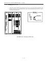
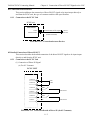
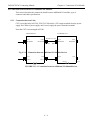
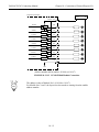
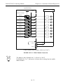
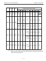
3.3 General Notes on Connection with Operation Panel
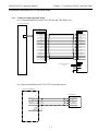
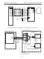
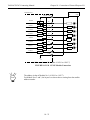
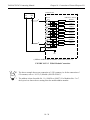
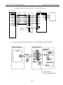
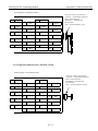
3.3.1
JANCD-JSP04 and Operator Panel
M A C H IN E O PER A TO R PA N EL
B A CK SID E V IEW
PC N C
C N 02
U R W 00205-1
JA N CD -JSP04
CN7
CN 8
CN 9
CNA
CN 04
U R W 00205-1
JA N C D -FC 861
C N 11
Y EN ET
Y EN ET
U R W 00251-2
C N 12
U R W 00251-2
This figure gives the general I/O card connections with PCNC.
1. Extended I/O board, FC 861, needs to be connected by a YENET cable from CN02 of PCNC
unit to the CN11 of FC 861 unit
2. Extended I/O board FC 861 is then connected by a YENET cable from CN04 of JSP04 to
CN12 of FC 861 unit.
3-8
YASNAC PCNC Connecting Manual
3.3.2
Chapter 3: Connection of PCNC Operation Panel
PCNC Connection Layout (Top View)
FIGURE 3.3.2.1 PCNC Connections Layout to CRT and PC Accessories
3-9
YASNAC PCNC Connecting Manual
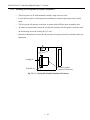
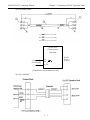
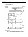
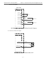
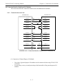
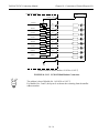
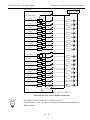
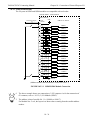
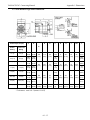
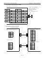
3.3.3
Chapter 3: Connection of PCNC Operation Panel
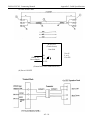
Extended I/O board FC861 and Remote machine pendent connections
REMOTE MACHINE PENDENT
PCNC UNIT
Manual Pulse
Generator
CN02
power supply
Connector
Emergency signal
Male
Female
YENET Cable
JANCD-FC861 (I/O Board)
CN11
CN12
UWR00251-2
YENET Cable
FIGURE 3.3.3.1 External FC861, Remote Machine Pendant, and PCNC connections
The figure illustrates the general I/O card and Remote Machine Pendant card connections with
the PCNC Unit.
Note: 1. FC861 board needs to be connected by a YENET cable from CN02 of the PCNC
Unit to CN11 of the FC861 I/O board.
2. Remote Machine Pendant is connected via a YENET cable from CN12 of the
FC861 I/O board to female connector for the Remote Machine Pendant.
3 - 10
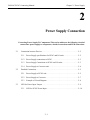
YASNAC PCNC Connecting Manual
Chapter 4: Connection of Manual Pulse Generator
4
Connection of Manual Pulse Generator
Connecting PCNC Operation Panel And Manual Pulse Generator
This section addresses the electrical connection of the Manual Pulse Generator.
4.1
Connection between Devices . . . . . . . . . . . . . . . . . . . . . . . . . . . . . . . . . . . . . . . . .4 - 2
4.1.1
4.2
Connection with PCNC Operation Panel . . . . . . . . . . . . . . . . . . . . . . . . . .4 - 2
Detailed Connection of Manual Pulse Generator . . . . . . . . . . . . . . . . . . . . . . . . . .4 - 3
4.2.1
Parallel I/F. . . . . . . . . . . . . . . . . . . . . . . . . . . . . . . . . . . . . . . . . . . . . . . . . .4 - 3
4.2.2
Non-Parallel I/F . . . . . . . . . . . . . . . . . . . . . . . . . . . . . . . . . . . . . . . . . . . . .4 - 4
4-1
YASNAC PCNC Connecting Manual
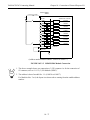
Chapter 4: Connection of Manual Pulse Generator
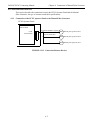
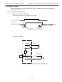
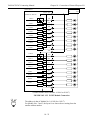
4.1 Connection Between Devices
This section describes the connection between the PCNC Operator Panel and the Manual
Pulse Generator, the type of connector and cable specifications.
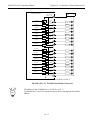
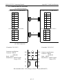
4.1.1
Connection of the PCNC operator Panel to the Manual Pulse Generator.
PCNC Operator Panel
JANCD-JSP02
JANCD-JSP04
.
.
UL20276 AWG28 x 10 pairs
CN01
10220-6202JL
10120-3000VE
(10120-52A0-008)
1HPG Manual pulse generator No.1
2HPG Manual pulse generator No.2
3HPG Manual pulse generator No.3
FIGURE 4.1.1.1 Connection Between Devices
4-2
YASNAC PCNC Connecting Manual
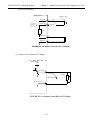
Chapter 4: Connection of Manual Pulse Generator
4.2 Connection Details of Manual Pulse Generator
Following connection details between the PCNC Operator Panel and the Manual pulse
generator
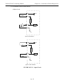
4.2.1
Parallel I / F
FIGURE 4.2.1.1 Detailed Connection of Manual Pulse Generator (Parallel I/F)
4-3
YASNAC PCNC Connecting Manual
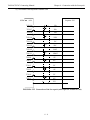
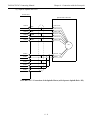
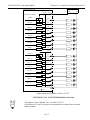
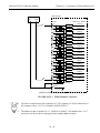
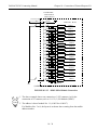
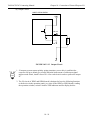
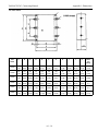
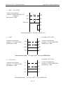
4.2.2
Chapter 4: Connection of Manual Pulse Generator
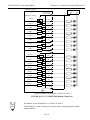
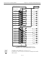
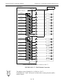
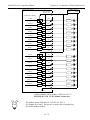
Non - parallel I / F
PCNC Operator Panel
JANCD-JSP02-1,-2
-JSP04-1,-2,-4
CN01-16
PAH1
CN01-17
0V
CN01-18
PBH1
CN01-19
0V
CN01-3
0V
CN01-6
5V
A
P
.
P
FG
CN01-12
PAH2
CN01-13
0V
CN01-14
PBH2
CN01-15
0V
CN01-2
0V
CN01-5
5V
PAH3
CN01-7
0V
CN01-10
PBH3
CN01-9
0V
CN01-1
0V
CN01-4
5V
..
B
P
P
1PHG
0V
+5V ~ 12V
A
..
B
MPG NO 2
2PHG
0V
P
.
FG
CN01-8
MPG NO 1
P
+5V ~ 12V
A
P
P
.
..
B
MPG NO 3
3PHG
0V
P
FG
+5V ~ 12V
FIGURE 4.2.2.1 Manual Pulse Generator Connection Details
POINT
1. JSP02-1, JSP02-2, JSP04-1, JSP04-2, JSP04-4 are provided with non-parallel I/F. With
JSP02-1, JSP04-1 only one manual pulse generator can be connected (one axis). With
JSP02-2, JSP04-2, JSP04-4 three manual pulse generators can be connected (three axis).
2. Use the cable within 5 meters for non-parallel type I/F. Connect FG and the cable to the
case using a metal cable clamp fitting.
4-4
YASNAC PCNC Connecting Manual
Chapter 5: Connection of Power ON/OFF Excluisve Signal
5
Connection of Power ON/OFF Exclusive Signal
This section addresses the connection of the Power On/Off Exclusive Signal
5.1
Connection between Devices . . . . . . . . . . . . . . . . . . . . . . . . . . . . . . . . . . . . . . . . . 5 - 2
5.1.1
5.2
Detailed Connection of Power ON/OFF Exclusive Signal . . . . . . . . . . . . . . . . . . 5 - 3
5.2.1
5.3
Connection to PCNC Unit . . . . . . . . . . . . . . . . . . . . . . . . . . . . . . . . . . . . . 5 - 2
Connection to PCNC Unit . . . . . . . . . . . . . . . . . . . . . . . . . . . . . . . . . . . . . 5 - 3
Details of Signal . . . . . . . . . . . . . . . . . . . . . . . . . . . . . . . . . . . . . . . . . . . . . . . . . . . 5 - 4
5.3.1
Servo Power ON (SVMX), Brake Release (BKX) Output . . . . . . . . . . . . 5 - 4
5.3.2
Emergency Stop (*ESP) Input . . . . . . . . . . . . . . . . . . . . . . . . . . . . . . . . . . 5 - 5
5.3.3
External Power ON/OFF (EON, EOF, ECOM) Input . . . . . . . . . . . . . . . . 5 - 5
5-1
YASNAC PCNC Connecting Manual
Chapter 5: Connection of Power ON/OFF Excluisve Signal
5.1 Connection between Devices
This section describes the connection between devices related to the Servo ON Shut Down
Exclusive signal, type of connector and cable specifications.
5.1.1
Connection to the PCNC Unit
PCNC
JZNC-JFC10
CN12
10220-52A2JL
UWR00263-1
UWR00272-1
Power magnetics,
Servo ON button,
Shut Down button
FIGURE 5.1.1.1 Connection between Devices
5-2
YASNAC PCNC Connecting Manual
Chapter 5: Connection of Power ON/OFF Excluisve Signal
5.2 Power ON/OFF Exclusive Signal Connection Details
This section describes the Power ON/OFF Exclusive Signal.
5.2.1
Connection to PCNC Unit
FIGURE 5.2.1.1 Power ON/OFF Exclusive Connection Details
POINT
For the relay of SVMX, NCMX and BKX use miniature relay 24V DC.
(Recommended part: Omron MY-4Z )
5-3
YASNAC PCNC Connecting Manual
Chapter 5: Connection of Power ON/OFF Excluisve Signal
5.3 Details of signals
This section describes the signals used in the power supply sequence.
5.3.1
Servo Power ON (SVMX) and Brake Release (BKX) Output
(1) Signal Names and Descriptions
SVMX:This output signal is closed when we press Power ON button after PCNC boots
up. The PLC starts working as soon as PCNC boots up. Use SVMX to turn ON the
main Contactor MC or (1MC) to feed main power to the Servo Pack.
BKX: This is the output to release the holding brake of the feed axis (vertical axis).
(2) Power Supply Sequence
Power supply sequence is executed as shown below:
a. Turn ON the power to the PCNC controller and I/O Power (DC 24V) simultaneously.
Power will be supplied to JCNC-JFC10 CNC board from the ISA bus of the PC.
PCNC will start booting up.
b. When the PCNC boots up, perform the Servo ON operation ( “closed”between EON
and ECOM ). SVMX output is closed and the servo power is turned ON.
c. After completion of servo ready (servo clamp status), BKX output is closed after the
time set by parameter. For the motor equipped with a brake, release the brake by this
signal.
d. After SVMX output is closed and the controller is ready, if external preparation has
been completed, close the MRD (machine ready completed) input of the general
purpose output module. Now Alarm lamp icon on the PCNC CRT is green and
operation is now possible.
.
5-4
YASNAC PCNC Connecting Manual
Chapter 5: Connection of Power ON/OFF Excluisve Signal
EON input
EOF input
*ESP input
SVMX output
Servo ready
completed
pm5400
pm5400
BKX output
MRD input
“RDY” “3302”
Alarm code
“3000” “2900”
“3000”
“RDY”
FIGURE 5.3.1.1 Power ON Sequence of Servo with PCNC Unit
5.3.2
Emergency Stop (*ESP) Input
When the emergency stop input circuit is opened, the controller stops all of the actions and
turns SVMX and BKX Off. During emergency stop of the general purpose I/O module, it
makes output (*ESP) “open”.
In response to the emergency stop input, the servo should DB stop, and the spindle stop with
brake using the delay circuit. (The spindle coasts after the main connector 1MC is “opened”
by the delay timer).
5.3.3
External Power ON/OFF (ECON, EOF, ECOM) Input
The controller may be turned ON/OFF by external input just like through the POWER ON/
OFF push button on the PCNC operator panel.
Setting the portion between EON and ECOM “closed” is like when the EOF and ECOM is
“closed” turns ON the logic circuit of the controller or the servo power.
Setting the portion between EON and ECOM “open” turns OFF the logic circuit of the
controller or the servo power.
5-5
YASNAC PCNC Connecting Manual
Chapter 6: Connection with the Servopack
6
Connection With The Servopack
Connection of the ServoPack to the PCNC Unit.
This section addresses the connection of the Servopack (Servo unit, Inverter,
and Converter Unit).
6.1
Connection between Devices . . . . . . . . . . . . . . . . . . . . . . . . . . . . . . . . . . . . . . . . .6 - 2
6.1.1
6.2
Connection between PCNC Unit, Servopack and Motor . . . . . . . . . . . . . .6 - 2
Connection Details . . . . . . . . . . . . . . . . . . . . . . . . . . . . . . . . . . . . . . . . . . . . . . . . .6 - 3
6.2.1
Connection between PCNC Unit and Servopack . . . . . . . . . . . . . . . . . . . .6 - 3
6.2.2
Connection of the Servomotor . . . . . . . . . . . . . . . . . . . . . . . . . . . . . . . . . .6 - 4
6.2.3
Connection of the Spindle Motor . . . . . . . . . . . . . . . . . . . . . . . . . . . . . . . .6 - 7
6.2.4
Selection of the Converter . . . . . . . . . . . . . . . . . . . . . . . . . . . . . . . . . . . . .6 - 9
6-1
YASNAC PCNC Connecting Manual
Chapter 6: Connection with the Servopack
6.1 Connection between Devices
6.1.1
Connection between PCNC, Servopack (Servo, Inverter and Converter units) and Motor
PCNC
PCNC Unit
MR8F
(MR8)
CNO1 (SVSP)
DUSB-ARA42-T11
SGDC
AJA(No.3axis)
4CN
2CN
MR-8RMA
1CN
10220-52A2JL
UWR00249-2
UWR00214-2
CN11
10220-52A2JL
10226-52A2JL
52CN
10120-300VE
10120-300VE
(10320-52A0-008)(10320-52A0-008)
Flat cable
.
PG
51CN
7CN
10220-52A2JL
SGDC
4CN
AJA(No.2axis)
2CN
.
10120-3000 E
(10320-52A0-008)
KQOO-SB type DE8400093
10120-3000VE
Separate PG
DC Bus bar
1CN
52CN
Flat cable
.
PG
51CN
7CN
.
SGDC
4CN
Separate PG
AJA(No.1axis)
2CN
DC Bus bar
1CN
52CN
Flat cable
.
PG
51CN
7CN
Seperate PG
.
Inverter Unit
10120-3000E
(1D320-52A0000 )
CIMR-M5N
4CN
2CN
Terminator MR-8RMA
connector 1CN
10220-52A2JL
DC Bus bar
10226-52A2JL
52CN
PG
10120-3000VE
51CN
.
.
8CN
10220-52A2JL
(10320-52A0-008)
Separate PG
Converter Unit
CIMR-MR5N
DC Bus bar
5CN
.
.
.
..
P/N
3φ
1φ
200/220/230V (AC Mains Power)
FIGURE 6.1.1.1 Connection between PCNC unit, Servopack and Motor
6-2
YASNAC PCNC Connecting Manual
Chapter 6: Connection with the Servopack
6.2 Connection Details
This section contains connection diagrams of the PCNC unit to the Servopack.
6.2.1
Connection Between PCNC Unit and Servopack
Converter unit
200/220/230 VAC
3Φ 1MCCB
R
P+
1MC L
N-
P+
CIMR-MR5N
R/L1
S
S/L2
T
T/L3
P1
P2
N1
N1
5 16 17 18
19 20 21 22
A1
A2
Inverter unit
24 V
Servo unit
N-
P+
N-
AJA (No.1 axis)
CIMR-M5N
SGDC-
15 16 17 18 15 16 17 18
19 20 21 22 19 20 21 22
24 V
51CN
52CN
1,2,7,8,9,10 1,2,7,8,9,10
11 12 13 14 11 12 13 14
0V
15 16 17 18 15 16 17 18
19 20 21 22 19 20 21 22
5CN1,2,7,8,9,10
11 12 13 14
0V
5CN-26
CONRDY
51CN-25
52CN-26
CONRDY
51CN-25
51CN-26
5CN-25
CONFLT
51CN-26
52CN-25
CONFLT
51CN-26
51CN-25
5CN-24
AXRUN
51CN-23
52CN-24
AXRUN
51CN-23
51CN-24
5CN-23
CONRST
51CN-24
52CN-23
CONRST
51CN-24
51CN-23
52CN-33
+24VIN
51CN-34
52CN-33
52CN-32
ESPO
51CN-31
52CN-32
52CN-30
ALM+
51CN-29
52CN-30
52CN-28
ALMC
51CN-27
52CN-28
52CN-3
S
51CN-4
52CN-3
52CN-5
*S
51CN-6
52CN-5
52CN-31
/EXT1
51CN-32
52CN-31
/EXT2
51CN-30
52CN-29
52CN-27
ESP1
51CN-28
52CN-27
52CN-6
BAT+
51CN-5
52CN-6
52CN-4
BAT-
51CN-3
52CN-4
11 12 13 14
11 12 13 14
Base plate
mounting screw
ALM -
{
{
Always connect
for termination unit
For monitoring zero speed
ALMC
1CN-7
1CN-8
R
4CN-4
*S
4CN-6
PAO
1CN-13
* PAO
1CN-14
SS
1CN-17
52CN-29
Brake power supply unit
OPR109
1
3
To motor brake
2
4
5
Base plate
mounting screw
Flat cable
6
FIGURE 6.2.1.1 Connection between PCNC unit and Servopack
6-3
YASNAC PCNC Connecting Manual
Chapter 6: Connection with the Servopack
For the I/O signals directly connected to the inverter previously, use the general purpose I/O ports.
The I/O addresses at the PCNC are shown below. For details of the signals, refer to the inverter’s
instruction manual.
Table 6.2.1.1 No. 1 Spindle Control Inputs with M-series (PLC → CNC)
Signal No.
3120
3121
Bit No.
Symbol
Name
D0
SPRDY-1
Machine ready
D1
SPEMG-1
Emergency stop
D2
SPFWD-1
Forward rotation
D3
SPREV-1
Reverse rotation
D4
SPTLH-1
Torque limit H
D5
SPTLL-1
Torque limit L
D6
SPSSC-1
Soft start canel
D0
SPCHW-1
Winding changeover signal
D1
SPPPI-1
Speed controller P-PI
changeover signal
D2
SPORT-1
Orientation signal
D3
SPLGR-1
L gear selection signal
D4
SPMGR-1
M gear selection signal
Table 6.2.1.2 No. 1 Spindle Control Outputs with M-series (PLC → CNC)
Signal No.
Bit No.
Symbol
Name
D0
SPZSPD-1
Zero-speed signal
D1
SPAGR-1
Speed match signal
D2
SPSDET-1
Speed detection signal
D3
SPTDET-1
Torque detection signal
D4
SPTLE-1
In torque limit signal
D5
SPORG-1
Load axis zero point signal
D6
SPORE-1
Orientation completed signal
D7
SPCHWE-1
Winding changeover signal
D0
SPFLT-1
Fault signal
D1
SPTALM-1
Error/Alarm signal
3660
3661
6-4
YASNAC PCNC Connecting Manual
6.2.2
Chapter 6: Connection with the Servopack
Servomotor Connection
(1) Servomotor with Built-in PG (common to both absolute and incremental encoders).
AJA
SGDC-
1
3
5
8
2CN-16
1
2
3
4
U
V
W
E
SM
A-PAI
2CN-17
P
2CN-18
2CN-19
C-PBI
P
2CN-14
2CN-15
B-*PAI
D-*PBI
E-PCI
P
F-*PCI
PG
2CN-10
R-RES
2CN-12
T-BATI
2CN-13
P
2CN-6
2CN-3
H-+5V
P
P
G-0V
H-+5V
2CN-4
2CN-1
G-0V
H-+5V
2CN-5
2CN-2
S-OBATI
P
G-0V
J-FG
FIGURE 6.2.2.1 Connection of the Servopack (with built-in PG)
6-5
YASNAC PCNC Connecting Manual
Chapter 6: Connection with the Servopack
(2) Servomotor With Separate Feedback Unit
AJA
SGDC-
Separate PG
7CN-16
7CN-17
PA
P
7CN-18
7CN-19
PB
P
7CN-14
7CN-15
P
P
P
0V
5V
P
7CN-4
7CN-1
OBAT
5V
7CN-5
7CN-2
*PC
BAT
7CN-6
7CN-3
*PB
PC
7CN-12
7CN-13
*PA
0V
5V
P
0V
FG
FIGURE 6.2.2.2 Connection of the Servopack (with Separate Feedback Unit)
6-6
YASNAC PCNC Connecting Manual
6.2.3
Chapter 6: Connection with the Servopack
Spindle Motor Connection
(1) Spindle Motor with Built-in PG
FIGURE 6.2.3.1 Connection of the Spindle Motor (with Built-in PG)
6-7
YASNAC PCNC Connecting Manual
Chapter 6: Connection with the Servopack
(2) Separate Spindle Drive PG
Inverter unit
Spindle Pulse Generator
2CN-16
SPA
2CN-17
*SPA
2CN-18
SPB
2CN-19
*SPB
2CN-14
SPC
2CN-15
*SPC
CNS-A PA
CNS-A *PA
P
CSN-C PB
CSN-R *PB
P
CSN-B PC
CSN-P *PC
P
PG
8CN-4
8CN-1
P
8CN-5
8CN-2
P
8CN-6
8CN-3
8CN-7
.
..
.
CSN-H +5V
CSN-K
0V
P
.
FIGURE 6.2.3.2 Connection of the Spindle Motor (with Separate Spindle Drive PG)
6-8
YASNAC PCNC Connecting Manual
6.2.4
Chapter 6: Connection with the Servopack
Selection of the Converter
It is necessary to select the converter based on satisfying the following three conditions:
CONDITION 1:
•
The rated output of the selected converter must be larger than the following value:
(Rated spindle output x 1.1) + (Total rated servomotor’s outputs x 0.6)
CONDITION 2:
•
The one second rating of the selected converter (2 times the continuous rating) must be greater
than the value shown below.
CONDITION 3:
•
The one minute rating of the selected converter (1.2 times the continuous rating) must be
larger than the momentary max. output value of spindle motor.
An example of converter selection procedure is show below:
Motors used: X-axis:
SGMG-20 (Max. 2000 r/min)
Y-axis:
SGMG-20 (Max. 2000 r/min)
Z-axis:
SGMG-30 (Max. 1500 r/min)
Spindle:
UAASWD-22CX1:
7.5kW (10HP)(cont. rating)
11 kW (15HP)(30 min. rating)
26 kW (34.8HP)(1 min. rating)
•
Continuous rating:
7.5kW x 1.1 + (1.08kW x 2 + 1.74kW) = 12.12kW( Selected 15 kw Converter)
•
Maximum momentary servo output:
5.99kW x 2 + 7.12 kW = 19.1kW ( Selected 11 kW converter )
•
Spindle acceleration/deceleration
Momentary max. output value of spindle motor: 26kW : ( 22 kW * 1.2 )
(converter with 22kW ratings)
From the calculation indicated above, the converter with 22kW rating that satisfies all
conditions that should be selected.
6-9
YASNAC PCNC Connecting Manual
Chapter 7: Connection of RS-23C
7
Connection of RS-232C
(Awaiting technical details. Contact Yaskawa Electric America)
This page is left intentionally BLANK.
7-1
YASNAC PCNC Connecting Manual
Chapter 8: Connection of Direct-IN/OUT Signals to the CNC
8
Connection of Direct IN-OUT Signal
to the CNC Unit
This section addresses the connection of the direct IN/OUT signals to be input/output
directly to and from the CNC unit.
8.1
Connection between Devices . . . . . . . . . . . . . . . . . . . . . . . . . . . . . . . . . . . . . . . . .8 - 2
8.1.1
8.2
Connection to the CNC Unit. . . . . . . . . . . . . . . . . . . . . . . . . . . . . . . . . . . .8 - 2
Detailed Connection of Direct IN/OUT . . . . . . . . . . . . . . . . . . . . . . . . . . . . . . . . .8 - 2
8.2.1
Connection to the CNC Unit. . . . . . . . . . . . . . . . . . . . . . . . . . . . . . . . . . . .8 - 2
8.2.2
Description of Signal . . . . . . . . . . . . . . . . . . . . . . . . . . . . . . . . . . . . . . . . .8 - 4
8.2.3
I/O Circuits on CNC side . . . . . . . . . . . . . . . . . . . . . . . . . . . . . . . . . . . . . .8 - 4
8-1
YASNAC PCNC Connecting Manual
Chapter 8: Connection of Direct-IN/OUT Signals to the CNC
8.1 Connection between Devices
This section addresses the connection of direct IN/OUT signals to be input/output directly to
and from the PCNC unit, the type of connector and the cable specifications.
8.1.1
Connection to the PCNC Unit
PCNC unit
JZNC-JFC10
CN14
10220-52A2JL
UL20276 AWG 28 X 10 pairs
10120-3000VE
(10320-52A0-008)
Direct
IN/OUT
FIGURE 8.1.1.1 Connection between Devices
8.2 Detailed Connection of Direct-IN/OUT
This section describes the detailed connection of the direct IN/OUT signals to be input/output
directly to and from the PCNC unit.
8.2.1
Connection to the PCNC Unit
(1) Connection of Direct IN Signal
(a) For 0 V Common
PCNC UNIT
JZNC-JFC10
CN14-10
+24V
COM
CN14-14
CN14-18
DIN1
CN14-2
0V
CN14-17
DIN2
CN14-1
0V
Direct IN 1
Direct IN 2
FIGURE 8.2.1.1 Connection Details of Direct IN (for 0V Common)
8-2
YASNAC PCNC Connecting Manual
Chapter 8: Connection of Direct-IN/OUT Signals to the CNC
(b) For +24V common
PCNC UNIT
CN14-1
0V
COM
CN14-14
CN14-18
DIN1
CN14-11
CN14-17
Direct IN 1
+24V
DIN2
CN14-10
Direct IN 2
+24V
FIGURE 8.2.1.2 Connection Details of Direct IN (for 24V Common)
(2) Connection of Direct OUT Signal
JZNC-JFC10
CN14-20
DOUT
.
Relay
CN14-1,2,3,9
0V
.
FIGURE 8.2.1.3 Connection Details of Direct OUT
8-3
YASNAC PCNC Connecting Manual
Chapter 8: Connection of Direct-IN/OUT Signals to the CNC
8.3 Description of Signal
This section addresses the contents of Direct IN/OUT signals to be input/output directly to/
from the PCNC unit.
8.3.1
I/O Circuits on PCNC side
(1) Input Circuit of Direct IN Signals
The time chart of direct IN signal is shown below.
Input waveform
Signal to be
received by PCNC
Time
Within 40µs
Within 10µs
FIGURE 8.3.1.1 Time Chart
(a) For 0V common
JZNC-JFC10
CN14-10
+24V
CN14-14
3.3kΩ
RV
.
About 7 mA
CN14-18
CN14-2
FIGURE 8.3.1.2 Input Circuit (for 0V Common)
8-4
YASNAC PCNC Connecting Manual
Chapter 8: Connection of Direct-IN/OUT Signals to the CNC
(b) For 24V common
JZNC-JFC10
About 7 mA
CN14-11
+24V
CN14-18
RV
3.3kΩ
.
CN14-14
CN14-1
FIGURE 8.3.1.3 Input Circuit (for 24V Common)
(2) Output Circuit of Direct OUT Signal
JZNC-JFC10
+24V
.
.
.
CN14-20
Relay
Max. 60mA
.
CN14-1,2,3,9
FIGURE 8.3.1.4 Output Circuit (Direct OUT Signal)
8-5
YASNAC PCNC Connecting Manual
Chapter 9: Connection of I/O Module
9
Connection of I/O Module
Connection of I/O Modules And Devices
This section addresses the connections between the CNC unit and I/O module.
9.1
Connection between Devices . . . . . . . . . . . . . . . . . . . . . . . . . . . . . . . . . . . . . . . . .9 - 2
9.1.1
9.2
Detailed Connection of I/O Module . . . . . . . . . . . . . . . . . . . . . . . . . . . . . . . . . . . .9 - 3
9.2.1
9.3
Connection between Units . . . . . . . . . . . . . . . . . . . . . . . . . . . . . . . . . . . . .9 - 3
Connection between Additional I/O Module devices. . . . . . . . . . . . . . . . . . . . . . .9 - 4
9.3.1
9.4
Connection between Units . . . . . . . . . . . . . . . . . . . . . . . . . . . . . . . . . . . . .9 - 2
Connection between Units . . . . . . . . . . . . . . . . . . . . . . . . . . . . . . . . . . . . .9 - 4
Detailed Connection of Additional I/O Module . . . . . . . . . . . . . . . . . . . . . . . . . . .9 - 5
9.4.1
Connection between Units . . . . . . . . . . . . . . . . . . . . . . . . . . . . . . . . . . . . .9 - 5
9-1
YASNAC PCNC Connecting Manual
Chapter 9: Connection of I/O Module
9.1 Connection between Devices
This section describes the connection between the PCNC unit and the I/O module, connector
type and cable specifications.
For a method to connect the I/O module, refer to the “YASNAC Module I/O Connecting
Manual”(Document No. DE9410364).
9.1.1
Connection between Units
PCNC Unit
I/O Module
JZNC-JFC10
CNO2 (ROI)
JEPMC-W6010-
MRP-8F01
DUSB-ARA42-T11
Fig. 9.1.1.1 Connection between Devices
JANCD-FC810/FC860/FC861
CN11
MR-8RMD2
CN12
CN13
172037-1
CN14
1720261
CN7
Power Supply
FIGURE 9.1.1.1 Connection between Devices
POINT
The length of the wiring between the PCNC unit and the I/O module should be as
short as possible.
9-2
YASNAC PCNC Connecting Manual
Chapter 9: Connection of I/O Module
9.2 I/O Module Connection Details
This section describes the connection details between the CNC unit and the I/O module.
9.2.1
Connection between Units
If FC810, FC815 or FC860 is used, +24V of standard power supply unit is output to CN7-1
and CN7-2 terminals. Use the twisted-pair shielded cable with characteristic impedance of
120Ω for the signal cable of /SIG AND SIG signals.
PCNC Unit
JZNC-JFC10
CN02 (RIO)
2
JANCD-FC810/FC815
/FC860/FC681
CN11-1
*S
3
Hood case
S
CN11-2
SH
CN11-3
FG
CN11-5
CN11-8
+5V
CN13-1
05V
Power Supply
CN13-4
(See note)
+24V
FU
024V
CN13-3
CN13-5
(See note)
FU
+24V
CN7-1
024V
(Only for FC810/FC815/FC860)
CN7-2
Power supply unit output
FIGURE 9.2.1.1 Connection Details of I/O Module
Note: Without the power supply having overcurrent protection or overcurrent protection
countermeasure for output signal (Section 10.3.2 “I/O Circuit of I/O Port”), a fuse
should be installed in the +24V line for I/O overcurrent protection. As the required
capacity of the fuse changes depending on the I/O points, refer to Section 10.3.3
“Power Supply for I/O Signal” for details (e.g. A 7.5 Amp fuse is required for 112
inputs and 96 outputs).
9-3
YASNAC PCNC Connecting Manual
Chapter 9: Connection of I/O Module
9.3 Connection between Devices of Additional I/O Modules
This section describes the connection details between additional I/O modules, type of
connector and cable specifications.
9.3.1
Connection between Units
CN7 is provided only in FC810, FC815, FC860 and is a 24V output terminal from the power
supply unit. When a power supply unit is used, supply the power from this terminal.
Note that CN7 is not arranged in FC861.
I/O Module No.1
I/O Module No.2
JANCD-FC810/FC815/FC860/FC861
JANCD-FC810/FC815/FC860/FC861
KEV-SB 0.2 X 1 pair
CN11
CM12
MR-8RMD2
CN11
MR-8RMD2
CM12
MR-8RMD2
MRP-8F01
MR-8RMD2
MRP-8F01
Fig. 9.3.1.1 Connection between Additional I/O Module Devices
CN13
CN14
172037-1
CN13
CN14
172037-1
172037-1
172037-1
CN7
CN7
FIGURE 9.3.1.1 Connection between Additional I/O ModuleDevices
9-4
YASNAC PCNC Connecting Manual
Chapter 9: Connection of I/O Module
9.4 Connection Details of Additional I/O Modules
This section describes the connection details between the additional I/O modules.
9.4.1
Connection between Units
I/O Module No.2
I/O Module No.1
JANCD-FC810/FC815/FC860/FC861
JANCD-FC810/FC815/FC860/FC861
CN12-1
/SIG
CN12-2
SIG
CN11-1
P
CN11-2
CN12-3
CN11-3
CN12-5
CN11-5
CN12-8
CN11-8
FG FG
CN14-1
+5V
CN13-1
CN14-4
0V
CN13-4
CN14-3
+24V
CN13-3
CN14-5
024V
CN13-5
CN17-1
CN7-2
+24V
024V
+24V
024V
CN7-1
CN7-2
Power output
FIGURE 9.4.1.1 Connection Details of Additional I/O ModuleDevice
(1) Connection of General Purpose I/O Module
•
•
Up to four (4) general purpose I/O modules can be connected (when using FC810, FC815
or FC860).
It is necessary to carry-out end processing at the last module of the general purpose I/O
modules.
9-5
YASNAC PCNC Connecting Manual
Chapter 9: Connection of I/O Module
PCNC UNIT
I/O Module
I/O Module
CNO2 (ROI)
CN11
CN12
CN11
JANCD-FC810/
FC815/FC860/
FC861
CN13
Power Supply
CN14
No.1 setting
TERMINATION (SW3)
ON/OFF
1
JANCD-FC810/
FC815/FC860/
FC861
2
CN13
No.1 setting
TERMINATION (SW3)
1
3
2
3
(When transferring to another I/O module) (For the last I/O module)
FIGURE 9.4.1.2 Connection of General Purpose I/O Module Device
(2) Setting of Short Pin (SW2)
By setting shorting pin SW2 of the I/O module (FC810, FC815, FC860, FC861), it is
possible to make logic “1” when the input contact is “closed” irrespective of common 0V/
24V.
INVERT (SW2)
1
2
3
(When ON)
1
2
3
(When OFF)
FIGURE 9.4.1.3 Setting of Short Pin
9-6
YASNAC PCNC Connecting Manual
Chapter 9: Connection of I/O Module
(3) Address setting of I/O module
I/O port address of I/O module can be set by the rotary switch (SW1).
SW1
CN11
CN12
CN13
CN14
CN7
(FC860)
SW3
TERMINATION
ADDRESS
INVERT
CN6
CN7
(FC810)
CN2
CN1
CN3
CN4
CN5
FIGURE 9.4.1.4 I/O Module (JANCD-FC810, FC815, FC860)
CN11
CN12
SW3
SW2
CN13
CN14
SW1
CNINT CNEXT
CN2
CN3
CN15
TERMINATION
INVERT ADDRESS
CN1
CN10
CN09
TM1
CN04
CN03
CN02
CN01
CN06
ADDRESS
TERMINATION
SW1
CN05
CN07
CN08
FIGURE 9.4.1.5 I/O Module (JANCD-FC861)
FIGURE 9.4.1.6 I/O Module (JANCD-JSP02, JSP04)
9-7
YASNAC PCNC Connecting Manual
Chapter 9: Connection of I/O Module
(4) Reverse Bit Area of the Board
The reverse bit area by the common status of each board is shown in Tables 9.4.1.1 and 9.4.1.2.
Table 9.4.1.1: Table of Bit Reverse Area
Common
Connector
Terminal
Name
FC810, FC815, FC860 Reverse Area
SW1=1
SW1=3
SW1=5
SW1=7
SW1=9
COM30
#1000, #1001
#1016, #1017
#1032, #1033
#1048, #1049
#1064, #1065
COM31
#1002, #1003
#1018, #1019
#1034, #1035
#1050, #1051
#1066, #1067
COM32
#1004
#1020
#1036
#1052
#1068
COM40
#1005, #1006
#1021, #1022
#1037, #1038
#1053, #1054
#1069, #1070
COM41
#1007, #1008
#1023, #1024
#1039, #1040
#1055, #1056
#1071, #1072
COM42
#1009
#1025
#1041
#1057
#1073
COM20
#1010, #1011
#1026, #1027
#1042, #1043
#1058, #1059
#1074, #1075
COM21
#1012
#1028
#1044
#1060
#1076
COM30
#1013
#1029
#1045
#1061
#1077
Table 9.4.1.2: Table of Bit Reverse Area
Common
Connector
Terminal
Name
FC861 Reverse Area
SW1=1
SW1=2
SW1=3
SW1=4
SW1=5
COM00
#1000, #1001
#1016, #1017
#1032, #1033
#1048, #1049
#1064, #1065
COM01
#1002, #1003
#1018, #1019
#1034, #1035
#1050, #1051
#1066, #1067
COM02
#1004
#1020
#1036
#1052
#1068
COM03
#1005, #1006
#1021, #1022
#1037, #1038
#1053, #1054
#1069, #1070
COM04
#1007, #1008
#1023, #1024
#1039, #1040
#1055, #1056
#1071, #1072
SW1=6
SW1=7
SW1=8
SW1=9
SW1=A
COM00
#1040, #1041
#1048, #1049
#1056, #1057
#1064, #1065
#1072 #1073
COM01
#1042
#1050
#1058
#1066
#1074
COM02
#1043, #1044
#1051, #1052
#1059, #1060
#1067, #1068
#1075 #1076
COM03
#1045
#1053
#1061
#1069
#1077
COM04
#1046, #1047
#1054, #1055
#1062, #1063
#1070, #1071
#1078, #1079
-
9-8
YASNAC PCNC Connecting Manual
Chapter 10: Connection of General Purpose I/O
10
Connection of General Purpose I/O
This section addresses the connections of general purpose I/O.
10.1
Connection between Devices . . . . . . . . . . . . . . . . . . . . . . . . . . . . . . . . . . . . . . . . .10 - 2
10.1.1 Connection of Signal Line with I/O Module . . . . . . . . . . . . . . . . . . . . . . .10 - 2
10.1.2 Connection between Devices . . . . . . . . . . . . . . . . . . . . . . . . . . . . . . . . . . .10 - 3
10.2
Detailed Connection of General Purpose I/O . . . . . . . . . . . . . . . . . . . . . . . . . . . . .10 - 4
10.2.1 FC810/FC815/FC860 Module . . . . . . . . . . . . . . . . . . . . . . . . . . . . . . . . . .10 - 4
10.2.2 FC861 Module . . . . . . . . . . . . . . . . . . . . . . . . . . . . . . . . . . . . . . . . . . . . . .10 - 27
10.2.3 JSP02/JSP04 Module . . . . . . . . . . . . . . . . . . . . . . . . . . . . . . . . . . . . . . . . .10 - 36
10.3
Description of General Purpose I/O Signal . . . . . . . . . . . . . . . . . . . . . . . . . . . . . .10 - 45
10.3.1 I/O Port . . . . . . . . . . . . . . . . . . . . . . . . . . . . . . . . . . . . . . . . . . . . . . . . . . . .10 - 45
10.3.2 I/O Circuit of I/O Port. . . . . . . . . . . . . . . . . . . . . . . . . . . . . . . . . . . . . . . . .10 - 47
10.3.3 Power Supply for I/O Signal. . . . . . . . . . . . . . . . . . . . . . . . . . . . . . . . . . . .10 - 57
10 - 1
YASNAC PCNC Connecting Manual
Chapter 10: Connection of General Purpose I/O
10.1Connection Between Devices
This section describes the connection details between the I/O module and the I/O signal
device, type of connector and the cable specifications.
10.1.1 Connection of the Signal Line with I/O Module
I/O Module
JANCD-FC810/FC815
CN1
MR-50RMD2
CN2
MR-20RMD2
CN3
MR-50RMD2
CN4
MR-50RMD2
CN5
MR-50RMD2
CN6
MR-50RMD2
C811KQVV-SB (DE8400095) 0.2mm2 x 50 cores
MRF-50F01 (MR-50L)
C812KQVV-SB (DE6428693) 0.2mm2 x 20 cores
MRF-20F01 (MR-20L)
C813KQVV-SB (DE8400095) 0.2mm2 x 50 cores
MRF-50F01 (MR-50L)
C814KQVV-SB (DE8400095) 0.2mm2 x 50 cores
MRF-50F01 (MR-50L)
C815KQVV-SB (DE8400095) 0.2mm2 x 50 cores
MRF-50F01 (MR-50L)
C816KQVV-SB (DE8400095) 0.2mm2 x 50 cores
MRF-50F01 (MR-50L)
For machine signal
C861 B-50S61.OM (Made by Oki Flex)
FRC5-AA50-2TOS
C862 B-20S60.OM (Made by Oki Flex)
FRC5-AA20-2TOS
C863 B-50S61.OM (Made by Oki Flex)
FRC5-AA50-2TOS
C864 B-50S61.OM (Made by Oki Flex)
FRC5-AA50-2TOS
C865 B-50S61.OM (Made by Oki Flex)
FRC5-AA50-2TOS
C866 B-50S61.OM (Made by Oki Flex)
FRC5-AA50-2TOS
For machine signal
I/O Module
JANCD-FC810/FC815
CN1
FRC5-C50S52T-OL
CN2
FRC5-C20S52T-OL
CN3
FRC5-C50S52T-OL
CN4
FRC5-C50S52T-OL
CN5
FRC5-C50S52T-OL
CN6
FRC5-C50S52T-OL
FIGURE 10.1.1.1 Connection between Devices
10 - 2
YASNAC PCNC Connecting Manual
Chapter 10: Connection of General Purpose I/O
10.1.2 Connection between Devices
I/O Module
JANCD-FC861
CN15
10178313-2
CN1
FRC5-C50S52T-OL
CN2
FRC5-C50S52T-OL
CN3
FRC5-C50S52T-OL
To be used at external power supply
C861 B-50S61.OM (Made by Oki Flex)
FRC5-AA50-2TOS
C862 B-50S61.OM (Made by Oki Flex)
FRC5-AA50-2TOS
C863 B-50S61.OM (Made by Oki Flex)
FRC5-AA50-2TOS
For machine signal
I/O Module
JANCD-JSPO4
CN09
FRC5-C50S52T-OL
C229B-50S61.OM (Made by Oki Flex)
CN08
FRC5-C50S52T-OL
C228 B-50S61.OM (Made by Oki Flex)
FRC5-AA50-2TO
C227 B-50S61.OM (Made by Oki Flex)
FRC5-AA50-2TO
CN07
FRC5-C50S52T-OL
FIGURE 10.1.2.1 Connection between Devices
10 - 3
For machine signal
YASNAC PCNC Connecting Manual
Chapter 10: Connection of General Purpose I/O
10.2Connection Details of General Purpose I/O
This section describes the connection details between the I/O module and the I/O signal device.
10.2.1 FC810/FC816/FC860 Module
JANCD-FC810/FC815/FC860
Power Supply
0V
+24V
CN4 Connector
.
Pin No.
Address No. Bit No.
(33)
#1000.0
(19)
#1000.1
(34)
#1000.2
(20)
#1000.3
(35)
#1000.4
(5)
#1000.5
(21)
#1000.6
(36)
#1000.7
(6)
#1001.0
(22)
#1001.1
(37)
#1001.2
(7)
#1001.3
(23)
#1001.4
(36)
#1001.5
(8)
#1001.6
(24)
#1001.7
(4)
.
COM 30
(1-3)
024
(Address number and bit number: #1000.0 to #1001.7)
FIGURE 10.2.1.1 FC810/FC815/FC860 Module Connection
POINT
1. The above example shows one connection of +24V common. As for the connection of
0V common, refer to “10.3.2 (1) Module (JANCD-FC810/FC815/FC860).”
2. The address is that of module No. 1 (#1000.0 to #1001.7). In modules Nos. 2 and 3, the
layout is as shown above starting from the smaller address number. For details, refer to
“10.3.1 I/O Port”.
10 - 4
YASNAC PCNC Connecting Manual
Chapter 10: Connection of General Purpose I/O
JANCD-FC810/FC815/FC860
Power Supply
0V
+24V
CN4 Connector
.
Pin No.
.
Address No. Bit No.
(39)
#1002.0
(9)
#1002.1
(25)
#1002.2
(40)
#1002.3
(10)
#1002.4
(26)
#1002.5
(41)
#1002.6
(11)
#1002.7
(27)
#1003.0
(42)
#1003.1
(12)
#1003.2
(43)
#1003.3
(13)
#1003.4
(44)
#1003.5
(14)
#1003.7
(45)
#1000.7
(28)
COM 30
(1-3)
024
(Address number and bit number: #1002.0 to #1003.7)
FIGURE 10.2.1.2 FC810/FC815/FC860 Module Connection
POINT
1.
The above example shows one connection of +24V common. As for the connection of
0V common, refer to “10.3.2 (1) Module (JANCD-FC810/FC815/FC860).”
2.
The address is that of module No. 1 (#1002.0 to #1003.7). In modules Nos. 2 and 3, the
layout is as shown above starting from the smaller address number. For details, refer to
“10.3.1 I/O Port”.
10 - 5
YASNAC PCNC Connecting Manual
Chapter 10: Connection of General Purpose I/O
JANCD-FC810/FC815/FC860
Power Supply
0V
+24V
CN4 Connector
.
Pin No.
.
Address No. Bit No.
(15)
#1004.0
(46)
#1004.1
(16)
#1004.2
(47)
#1004.3
(17)
#1004.4
(48)
#1004.5
(18)
#1004.6
(49)
#1004.7
(29)
COM 32
024
(Address number and bit number: #1004.0 to #1004.7)
FIGURE 10.2.1.3 FC810/FC815/FC860 Module Connection
1. The above example shows one connection of +24V common. As for the connection of
0V common, refer to “10.3.2 (1) Module (JANCD-FC810/FC815/FC860).”
POINT
2. The address is that of module No. 1 (#1004.0 to #1004.7). In modules Nos. 2 and 3, the
layout is as shown above starting from the smaller address number. For details, refer to
“10.3.1 I/O Port”.
10 - 6
YASNAC PCNC Connecting Manual
Chapter 10: Connection of General Purpose I/O
JANCD-FC810/FC815/FC860
Power Supply
0V
+24V
CN5 Connector
.
.
Pin No.
Address No. Bit No.
(23)
#1005.0
(22)
#1005.1
(21)
#1005.2
(20)
#1005.3
(39)
#1005.4
(38)
#1005.5
(7)
#1005.6
(6)
#1005.7
(12)
#1006.0
(11)
#1006.1
(25)
#1006.2
(24)
#1006.3
(10)
#1006.4
(40)
#1006.5
(9)
#1006.6
(8)
#1006.7
(4)
COM 40
(1-3)
024
(Address number and bit number: #1005.0 to #1006.7)
FIGURE 10.2.1.4 FC810/FC815/FC860 Module Connection
1. The above example shows one connection of +24V common. As for the connection of
0V common, refer to “10.3.2 (1) Module (JANCD-FC810/FC815/FC860).”
POINT
2. The address is that of module No. 1 (#1005.0 to #1006.7). In modules Nos. 2 and 3, the
layout is as shown above starting from the smaller address number. For details, refer to
“10.3.1 I/O Port”.
10 - 7
YASNAC PCNC Connecting Manual
Chapter 10: Connection of General Purpose I/O
JANCD-FC810/FC815/FC860
Power Supply
0V
+24V
CN5 Connector
.
.
Pin No.
Address No. Bit No.
(18)
#1007.0
(17)
#1007.1
(16)
#1007.2
(15)
#1007.3
(14)
#1007.4
(5)
#1007.5
(37)
#1007.6
(13)
#1007.7
(36)
#1008.0
(35)
#1008.1
(34)
#1008.2
(33)
#1008.3
(19)
#1008.4
(27)
#1008.5
(26)
#1008.6
(41)
#1008.7
(28)
COM 41
(1-3)
024
(Address number and bit number: #1007.0 to #1008.7)
FIGURE 10.2.1.5 FC810/FC815/FC860 Module Connection
1. The above example shows one connection of +24V common. As for the connection of
0V common, refer to “10.3.2 (1) Module (JANCD-FC810/FC815/FC860).”
POINT
2. The address is that of module No. 1 (#1007.0 to #1008.7). In modules Nos. 2 and 3, the
layout is as shown above starting from the smaller address number. For details, refer to
“10.3.1 I/O Port”.
10 - 8
YASNAC PCNC Connecting Manual
Chapter 10: Connection of General Purpose I/O
JANCD-FC810/FC815/FC860
Power Supply
0V
+24V
CN5 Connector
.
Pin No.
Address No. Bit No.
(49)
#1009.0
(48)
#1009.1
(47)
#1009.2
(46)
#1009.3
(45)
#1009.4
(44)
#1009.5
(43)
#1009.6
(42)
#1009.7
(29)
.
COM 42
(1-3)
024
(Address number and bit number: #1009.0 to #1009.7)
FIGURE 10.2.1.6 FC810/FC815/FC860 Module Connection
1. The above example shows one connection of +24V common. As for the connection of
0V common, refer to “10.3.2 (1) Module (JANCD-FC810/FC815/FC860).”
POINT
2. The address is that of module No. 1 (#1009.0 to #1009.7). In modules Nos. 2 and 3,
the layout is as shown above starting from the smaller address number. For details,
refer to“10.3.1 I/O Port”.
10 - 9
YASNAC PCNC Connecting Manual
Chapter 10: Connection of General Purpose I/O
JANCD-FC810/FC815/FC860
Power Supply
0V
+24V
CN3 Connector
.
Pin No.
.
Address No. Bit No.
(39)
#1010.0
(9)
#1010.1
(25)
#1010.2
(40)
#1010.3
(10)
#1010.4
(26)
#1010.5
(41)
#1010.6
(11)
#1010.7
(27)
#1011.0
(42)
#1011.1
(12)
#1011.2
(43)
#1011.3
(13)
#1011.4
(44)
#1011.5
(14)
#1011.6
(45)
#1011.7
(28)
COM 20
(1-4)
024
(Address number and bit number: #1010.0 to #1011.7)
FIGURE 10.2.1.7 FC810/FC815/FC860 Module Connection
1. The above example shows one connection of +24V common. As for the connection of
0V common, refer to “10.3.2 (1) Module (JANCD-FC810/FC815/FC860).”
POINT
2. The address is that of module No. 1 (#1010.0 to #1011.7). In modules Nos. 2 and 3, the
layout is as shown above starting from the smaller address number. For details, refer
to “10.3.1 I/O Port”.
10 - 10
YASNAC PCNC Connecting Manual
Chapter 10: Connection of General Purpose I/O
JANCD-FC810/FC815/FC860
Power Supply
0V
+24V
CN3 Connector
.
Pin No.
Address No. Bit No.
(15)
#1012.0
(46)
#1012.1
(16)
#1012.2
(47)
#1012.3
(17)
#1012.4
(48)
#1012.5
(18)
#1012.6
(49)
#1012.7
(29)
.
COM 21
(1-4)
024
(Address number and bit number: #1012.0 to #1012.7)
FIGURE 10.2.1.8 FC810/FC815/FC860 Module Connection
1. The above example shows one connection of +24V common. As for the connection of
0V common, refer to “10.3.2 (1) Module (JANCD-FC810/FC815/FC860).”
POINT
2. The address is that of module No. 1 (#1012.0 to #1012.7). In modules Nos. 2 and 3, the
layoutis as shown above starting from the smaller address number. For details, refer to
“10.3.1 I/O Port”.
10 - 11
YASNAC PCNC Connecting Manual
Chapter 10: Connection of General Purpose I/O
JANCD-FC810/FC815/FC860
Power Supply
0V
+24V
CN2 Connector
.
Pin No.
Address No. Bit No.
(1)
#1013.0
(46)
#1013.1
(2)
#1013.2
(8)
#1013.3
(15)
#1013.4
(3)
#1013.5
(9)
#1013.6
(16)
#1013.7
(19)
.
COM 10
(18)
024
(Address number and bit number: #1013.0 to #1013.7)
FIGURE 10.2.1.9 FC810/FC815/FC860 Module Connection
1. The above example shows one connection of +24V common. As for the connection of
0V common, refer to “10.3.2 (1) Module (JANCD-FC810/FC815/FC860).”
POINT
2. The address is that of module No. 1 (#1013.0 to #1013.7). In modules Nos. 2 and 3, the
layout is as shown above starting from the smaller address number. For details, refer to
“10.3.1 I/O Port”.
10 - 12
YASNAC PCNC Connecting Manual
Chapter 10: Connection of General Purpose I/O
JANCD-FC810/FC860
CN1 connector
Pin No. (28)
#1100.0
.
POWER SUPPLY
+24V
0V
(25)
#1100.1
(26)
#1100.2
(27)
#1100.3
(41)
#1100.4
(8)
#1100.5
(7)
#1100.6
(6)
#1100.7
(5)
(29)
#1101.0
.
(24)
#1101.1
(23)
#1101.2
(22)
#1101.3
(21)
#1101.4
(20)
#1101.5
(19)
#1101.6
(10)
#1101.7
(9)
.
.
.
.
.
.
.
.
.
.
.
.
.
.
.
.
(1-4)
(Address number and bit number: #1100.0 to #1101.7)
FIGURE 10.2.1.10 FC810/FC860 Module Connection
POINT
The address is that of Module No.1 (#1100.0 to 1101.7).
For Module Nos. 2 and 3, the layout is as shown above starting from the smaller
address.
10 - 13
YASNAC PCNC Connecting Manual
Chapter 10: Connection of General Purpose I/O
JANCD-FC810/FC860
CN1 connector
Pin No. (30)
#1102.0
(40)
.
#1102.1
(39)
#1102.2
(38)
#1102.3
(37)
#1102.4
(36)
#1102.5
(35)
#1102.6
(34)
#1102.7
(33)
(31)
#1103.0
(18)
.
#1103.1
(17)
#1103.2
(16)
#1103.3
(15)
#1103.4
(14)
#1103.5
(13)
#1103.6
(12)
#1103.7
(11)
(1-4)
.
POWER SUPPLY
+24V
0V
.
.
.
.
.
.
.
.
.
.
.
.
.
.
.
.
(Address number and bit number: #1102.0 to #1103.7)
FIGURE 10.2.1.11 FC810/FC860 Module Connection
POINT
The address is that of Module No.1 (#1102.0 to 1103.7).
For Module Nos. 2 and 3, the layout is as shown above starting from the smaller
address number.
10 - 14
YASNAC PCNC Connecting Manual
Chapter 10: Connection of General Purpose I/O
JANCD-FC810/FC860
CN1 connector
Pin No. (32)
#1104.0
.
POWER SUPPLY
+24V
0V
(49)
#1104.1
(48)
#1104.2
(47)
#1104.3
(46)
#1104.4
(45)
#1104.5
(44)
#1104.6
(43)
#1104.7
(42)
(1-4)
.
.
.
.
.
.
.
.
024
(Address number and bit number: #1104.0 to #1104.7)
FIGURE 10.2.1.12 FC810/FC860 Module Connection
POINT
The address is that of Module No.1 (#1104.0 to 1104.7).
For Module Nos. 2 and 3, the layout is as shown above starting from the smaller
address number.
10 - 15
YASNAC PCNC Connecting Manual
Chapter 10: Connection of General Purpose I/O
JANCD-FC810/FC860
CN2 connector
Pin No. (20)
#1105.0
.
POWER SUPPLY
+24V
0V
(4)
#1105.1
(10)
#1105.2
(17)
#1105.3
(5)
#1105.4
(11)
#1105.5
(6)
#1105.6
(12)
#1105.7
(7)
(18)
.
.
.
.
.
.
.
.
024
(Address number and bit number: #1105.0 to #1105.7)
FIGURE 10.2.1.13 FC810/FC860 Module Connection
POINT
The address is that of Module No.1 (#1105.0 to 1105.7).
For Module Nos. 2 and 3, the layout is as shown above starting from the smaller
address number.
10 - 16
YASNAC PCNC Connecting Manual
Chapter 10: Connection of General Purpose I/O
JANCD-FC810/FC860
CN3 connector
Pin No. (31)
POWER SUPPLY
+24V
0V
Address No. Bit No.
#1106.0
(33)
.
#1106.1
(19)
#1106.2
(34)
#1106.3
(20)
#1106.4
(35)
#1106.5
(5)
#1106.6
(21)
#1106.7
(36)
(32)
#1107.0
(6)
.
#1107.1
(22)
#1107.2
(37)
#1107.3
(7)
#1107.4
(23)
#1107.5
(38)
#1107.6
(8)
#1107.7
(24)
(1-4)
.
.
.
.
.
.
.
.
.
.
.
.
.
.
.
.
024
(Address number and bit number: #1106.0 to #1107.7)
FIGURE 10.2.1.14 FC810/FC860 Module Connection
POINT
The address is that of Module No.1 (#1106.0 to 1107.7).
For Module Nos. 2 and 3, the layout is as shown above starting from the smaller
address number.
10 - 17
YASNAC PCNC Connecting Manual
Chapter 10: Connection of General Purpose I/O
JANCD-FC810/F860
CN6 connector
Pin No. (29)
Anchor No. Bit No.
#1108.0
.
POWER SUPPLY
+24V
0V
(18)
.
#1108.1
(17)
#1108.2
(16)
#1108.3
(15)
#1108.4
(14)
#1108.5
(13)
#1108.6
(12)
#1108.7
(11)
(30)
#1109.0
.
(49)
.
#1109.1
(48)
#1109.2
(47)
#1109.3
(46)
#1109.4
(45)
#1109.5
(44)
#1109.6
(43)
#1109.7
(42)
.
.
.
.
.
.
.
.
.
.
.
.
.
.
.
.
(1-4)
024
(Address number and bit number: #1108.0 to #1109.7)
FIGURE 10.2.1.15 FC810/FC860 Module Connection
POINT
The address is that of Module No.1 (#1108.0 to 1109.7).
For Module Nos. 2 and 3, the layout is as shown above starting from the smaller
address number.
10 - 18
YASNAC PCNC Connecting Manual
Chapter 10: Connection of General Purpose I/O
JANCD-FC810/FC860
CN6 connector
Pin No. (31)
Anchor No. Bit No.
#1110.0
.
POWER SUPPLY
+24V
0V
(26)
.
#1110.1
(25)
#1110.2
(24)
#1110.3
(23)
#1110.4
(22)
#1110.5
(21)
#1110.6
(20)
#1110.7
(19)
(32)
#1111.0
(40)
.
#1111.1
(39)
#1111.2
(38)
#1111.3
(37)
#1111.4
(36)
#1111.5
(35)
#1111.6
(34)
#1111.7
(33)
(1-4)
.
.
.
.
.
.
.
.
.
.
.
.
.
.
.
.
024
(Address number and bit number: #1110.0 to #1111.7)
FIGURE 10.2.1.16 FC810/FC860 Module Connection
POINT
The address is that of Module No.1 (#1110.0 to 1111.7).
For Module Nos. 2 and 3, the layout is as shown above starting from the smaller
address number.
10 - 19
YASNAC PCNC Connecting Manual
Chapter 10: Connection of General Purpose I/O
JANCD-FC815
CN1 connector
Pin No. (28)
Anchor No. Bit No.
#1100.0
.
POWER SUPPLY
0V
+24V
(25)
.
#1100.1
(26)
#1100.2
(27)
#1100.3
(41)
#1100.4
(8)
#1100.5
(7)
#1100.6
(6)
#1100.7
(5)
(29)
#1101.0
(24)
.
#1101.1
(23)
#1101.2
(22)
#1101.3
(21)
#1101.4
(20)
#1101.5
(19)
#1101.6
(10)
#1101.7
(9)
(1-4)
.
.
.
.
.
.
.
.
.
.
.
.
.
.
.
.
024
(Address number and bit number: #1100.0 to #1101.7)
FIGURE 10.2.1.17 FC815 Module Connection
POINT
The address is that of Module No.1 (#1100.0 to 1110.7).
For Module Nos. 2 and 3, the layout is as shown above starting from the smaller
address number.
10 - 20
YASNAC PCNC Connecting Manual
Chapter 10: Connection of General Purpose I/O
JANCD-FC810/FC815
CN1 connector
Pin No. (30)
Anchor No. Bit No.
#1102.0
.
POWER SUPPLY
0V
+24V
(40)
.
#1102.1
(39)
#1102.2
(38)
#1102.3
(37)
#1102.4
(36)
#1102.5
(35)
#1102.6
(34)
#1102.7
(33)
(31)
#1103.0
(18)
.
#1103.1
(17)
#1103.2
(16)
#1103.3
(15)
#1103.4
(14)
#1103.5
(13)
#1103.6
(12)
#1103.7
(11)
(1-4)
024
(Address number and bit number: #1102.0 to #1103.7)
FIGURE 10.2.1.18 FC815 Module Connection
POINT
The address is that of Module No.1 (#1102.0 to 1103.7).
For Module Nos.2 and 3, the layout is as shown above starting from
the smaller address number.
10 - 21
.
.
.
.
.
.
.
.
.
.
.
.
.
.
.
.
YASNAC PCNC Connecting Manual
Chapter 10: Connection of General Purpose I/O
JANCD-FC815
CN1 connector
Pin No. (32)
#1104.0
.
POWER SUPPLY
0V
+24V
(49 )
#1104.1
(48)
#1104.2
(47)
#1104.3
(46)
#1104.4
(45)
#1104.5
(44)
#1104.6
(43)
#1104.7
(42)
.
.
.
.
.
.
.
(1-4)
024
(Address number and bit number: #1104.0 to #1104.7)
FIGURE 10.2.1.19 FC815 Module Connection
POINT
The address is that of Module No.1 (#1104.0 to 1104.7).
For Module Nos.2 and 3, the layout is as shown above starting from the smaller
address number.
10 - 22
YASNAC PCNC Connecting Manual
Chapter 10: Connection of General Purpose I/O
JANCD-FC815
CN2 connector
Pin No. (20)
#1105.0
.
POWER SUPPLY
0V
+24V
(4 )
#1105.1
(10)
#1105.2
(17)
#1105.3
(5)
#1105.4
(11)
#1105.5
(6)
#1105.6
(12)
#1105.7
(7)
.
.
.
.
.
.
.
(18)
024
(Address number and bit number: #1105.0 to #1105.7)
FIGURE 10.2.1.20 FC815 Module Connection
POINT
The address is that of Module No.1 (#1105.0 to 1105.7).
For Module Nos. 2 and 3, the layout is as shown above starting from the smaller
address number.
10 - 23
YASNAC PCNC Connecting Manual
Chapter 10: Connection of General Purpose I/O
JANCD-FC815
CN3 connector
Pin No. (31)
POWER SUPPLY
+0V
+24V
Anchor No. Bit No.
#1106.0
(33)
.
#1106.1
(19)
#1106.2
(34)
#1106.3
(20)
#1106.4
(35)
#1106.5
(5)
#1106.6
(21)
#1106.7
(36)
(32)
#1107.0
(6)
.
#1107.1
(22)
#1107.2
(37)
#1107.3
(7)
#1107.4
(23)
#1107.5
(38)
#1107.6
(8)
#1107.7
(24)
.
.
.
.
.
.
.
.
.
.
.
.
.
.
.
(1-4)
024
(Address number and bit number: #1106.0 to #1107.7)
FIGURE 10.2.1.21 FC815 Module Connection
POINT
The address is that of Module No.1 (#1106.0 to 1107.7).
For Module Nos. 2 and 3, the layout is as shown above starting from the smaller
address number.
10 - 24
YASNAC PCNC Connecting Manual
Chapter 10: Connection of General Purpose I/O
JANCD-FC815
CN3 connector
Pin No. (29)
Anchor No. Bit No.
#1108.0
.
.
POWER SUPPLY
0V
+24V
(18)
#1108.1
(17)
#1108.2
(16)
#1108.3
(15)
#1108.4
(14)
#1108.5
(13)
#1108.6
(12)
#1108.7
(11)
(30)
#1109.0
.
(49)
#1109.1
(48)
#1109.2
(47)
#1109.3
(46)
#1109.4
(45)
#1109.5
(44)
#1109.6
(43)
#1109.7
(42)
(1-4)
(Address number and bit number: #1108.0 to #1109.7)
FIGURE 10.2.1.22 FC815 Module Connection
POINT
The address is that of Module No.1 (#1108.0 to 1109.7).
For Module Nos. 2 and 3, the layout is as shown above starting from the
smaller address number.
10 - 25
.
.
.
.
.
.
.
.
.
.
.
.
.
.
.
.
YASNAC PCNC Connecting Manual
Chapter 10: Connection of General Purpose I/O
JANCD-FC815
CN6 connector
Pin No. (31)
POWER SUPPLY
0V
+24V
Anchor No. Bit No.
#1110.0
(26)
.
#1110.1
(25)
#1110.2
(24)
#1110.3
(23)
#1110.4
(22)
#1110.5
(21)
#1110.6
(20)
#1110.7
(19)
(32)
#1111.0
(39)
.
#1111.1
(38)
#1111.2
(37)
#1111.3
(37)
#1111.4
(36)
#1111.5
(35)
#1111.6
(34)
#1111.7
(33)
.
.
.
.
.
.
.
.
.
.
.
.
.
.
.
.
(1-4)
024
(Address number and bit number: #1110.0 to #1111.7)
FIGURE 10.2.1.23 FC815 Module Connection
POINT
The address is that of Module No.1 (#1110.0 to 1111.7).
For Module Nos. 2 and 3, the layout is as shown above starting from the smaller
address number.
10 - 26
YASNAC PCNC Connecting Manual
Chapter 10: Connection of General Purpose I/O
10.2.2 FC861 Module
JANCD-FC861
Power Supply
0V
+24V
CN1Connector
.
Pin No.
Address No. Bit No.
(1)
#1000.0
(2)
(3)
#1000.1
#1000.2
(4)
#1006.3
(5)
#1000.4
(6)
#1000.5
(7)
#1000.6
(8)
#1000.7
(9)
.
.
. .
. .
. .
. .
. .
. .
. .
. .
. .
. .
. .
. .
. .
. .
. .
#1001.0
(10)
#1001.1
(11)
#1001.2
(12)
#1001.3
(13)
#1001.4
(14)
#1001.5
(15)
#1001.6
(16)
#1001.7
(17)
COM 00
(43-46)
(Address number and bit number: #1000.0 to #1001.7)
024
FIGURE 10.2.2.1 FC861 Module Connection
POINT
1. The above example shows one connection of +24V common. As for the connection of
0V common, refer to “10.3.2 (1) Module (JANCD-FC861).”
2. The address is that of module No. 1-1 (#1000.0 to #1001.7). For Modules Nos. 2 to 7,
the layout is as shown above starting from the smaller address number.
10 - 27
YASNAC PCNC Connecting Manual
Chapter 10: Connection of General Purpose I/O
JANCD-FC861
Power Supply
0V
+24V
CN1 Connector
.
Pin No.
.
.
.
.
.
.
.
.
Address No. Bit No.
(19)
(20)
(21)
(22)
(23)
(24)
(25)
(26)
(18)
.
#1002.0
.
.
.
.
.
.
.
#1002.1
#1002.2
#1002.3
#1002.4
#1002.5
#1002.6
#1002.7
COM 01
(43-46)
024
(Address number and bit number: #1002.0 to #1002.7)
FIGURE 10.2.2.2 FC861 Module Connection
POINT
1. The above example shows one connection of +24V common. As for the connection of
0V common, refer to “10.3.2 (2) Module (JANCD-FC861).”
2. The address is that of module No. 1-1 (#1002.0 to #1002.7). For Modules Nos. 2 to 7,
the layout is as shown above starting from the smaller address number.
10 - 28
YASNAC PCNC Connecting Manual
Chapter 10: Connection of General Purpose I/O
JANCD-FC861
Power Supply
0V
+24V
CN2 Connector
.
Pin No.
Address No. Bit No.
(1)
#1003.0
(2)
(3)
.
.
.
.
.
.
.
.
.
.
.
.
.
.
.
.
(4)
(5)
(6)
(7)
(8)
(9)
(10)
(11)
(12)
(13)
(14)
(15)
(16)
.
(17)
.
.
.
.
.
.
.
.
.
.
.
.
.
.
.
#1003.1
#1003.2
#1003.3
#1003.4
#1003.5
#1003.6
#1004.7
#1004.0
#1004.1
#1004.2
#1004.3
#1004.4
#1004.5
#1004.6
#1004.7
COM 02
(43-46)
024
(Address number and bit number: #1003.0 to #1004.7)
FIGURE 10.2.2.3 FC861 Module Connection
1.
The above example shows one connection of +24V common. As for the connection of
0V common, refer to “10.3.2 (1) Module (JANCD-FC861).”
2.
The address is that of module No. 1-1 (#1003.0 to #1004.7). For Modules Nos. 2 to 7,
the layout is as shown above starting from the smaller address number.
POINT
10 - 29
YASNAC PCNC Connecting Manual
Chapter 10: Connection of General Purpose I/O
JANCD-FC861
CN2 Connector
Power Supply
0V
+24V
.
Pin No.
.
.
.
.
.
.
.
.
Address No. Bit No.
(19)
(20)
(21)
(22)
(23)
(24)
(25)
(26)
.
(18)
#1005.0
.
.
.
.
.
.
.
#1005.1
#1005.2
#1005.3
#1005.4
#1005.5
#1005.6
#1005.7
COM 03
(43-46)
024
(Address number and bit number: #1005.0 to #1005.7)
FIGURE 10.2.2.4 FC861 Module Connection
1.
The above example shows one connection of +24V common. As for the connection
of 0V common, refer to “10.3.2 (2) Module (JANCD-FC861).”
2.
The address is that of module No. 1-1 (#1005.0 to #1005.7). For Modules Nos. 2 to 7,
the layout is as shown above starting from the smaller address number.
POINT
10 - 30
YASNAC PCNC Connecting Manual
Chapter 10: Connection of General Purpose I/O
JANCD-FC861
Power Supply
0V
+24V
CN3 Connector
.
Pin No.
Address No. Bit No.
(1)
#1006.0
(2)
(3)
.
.
.
.
.
.
.
.
.
.
.
.
.
.
.
.
(4)
(5)
(6)
(7)
(8)
(9)
(10)
(11)
(12)
(13)
(14)
(15)
(16)
(17)
.
.
.
.
.
.
.
.
.
.
.
.
.
.
.
.
#1006.1
#1006.2
#1006.3
#1006.4
#1006.5
#1006.6
#1006.7
#1007.0
#1007.1
#1007.2
#1007.3
#1007.4
#1007.5
#1007.6
#1007.7
COM 04
(43-46)
024
(Address number and bit number: #1006.0 to #1007.7)
FIGURE 10.2.2.5 FC861 Module Connection
POINT
1. The above example shows one connection of +24V common. As for the connection of
0V common, refer to “10.3.2 (2) Module (JANCD-FC861).”
2. The address is that of module No. 1-1 (#1006.0 to #1007.7). For Modules Nos. 2 to 7,
the layout is as shown above starting from the smaller address number.
10 - 31
YASNAC PCNC Connecting Manual
Chapter 10: Connection of General Purpose I/O
JANCD-FC861
+24V
CN1 connector
Pin No.
+24V
POWER SUPPLY
0V
Anchor No. Bit No.
#1100.0
.
.
.
.
.
.
.
.
.
.
.
.
.
.
.
.
(27)
.
#1100.1
(28)
#1100.2
(29)
#1100.3
(30)
#1100.4
(31)
#1100.5
(32)
#1100.6
(33)
#1100.7
(34)
+24V
#1101.0
(35)
.
#1101.1
(36)
#1101.2
(37)
#1101.3
(38)
#1101.4
(39)
#1101.5
(40)
#1101.6
(41)
#1101.7
(42)
(43-46)
024
To CN15-1
To CN15-3
(Address number and bit number: #1100.0 to #1101.7)
FIGURE 10.2.2.6 FC861 Module Connection
POINT
The above address is that of Module No.1-1 (#1100.0 to 1101.7).
For Module Nos. 2 to 7, the layout is as shown above starting from the smaller
address number.
10 - 32
YASNAC PCNC Connecting Manual
Chapter 10: Connection of General Purpose I/O
JANCD-FC861
+24V
CN2 connector
Pin No.
+24V
POWER SUPPLY
0V
Anchor No. Bit No.
#1102.0
.
.
.
.
.
.
.
.
.
.
.
.
.
.
.
.
(27)
.
#1102.1
(28)
#1102.2
(29)
#1102.3
(30)
#1102.4
(31)
#1102.5
(32)
#1102.6
(33)
#1102.7
(34)
+24V
#1103.0
(35)
.
#1103.1
(36)
#1103.2
(37)
#1103.3
(38)
#1103.4
(39)
#1103.5
(40)
#1103.6
(41)
#1103.7
(42)
(43-46)
024
To CN15-1
To CN15-3
(Address number and bit number: #1102.0 to #1103.7)
FIGURE 10.2.2.7 FC861 Module Connection
POINT
The above address is that of Module No.1-1 (#1102.0 to 1103.7).
For Module Nos. 2 to 7, the layout is as shown above starting from the smaller
address number.
10 - 33
YASNAC PCNC Connecting Manual
Chapter 10: Connection of General Purpose I/O
JANCD-861
+24V
CN3 connector
Pin No.
+24V
POWER SUPPLY
0V
Address No. Bit No.
#1104.0
.
.
.
.
.
.
.
.
.
.
.
.
.
.
.
.
(19)
.
#1104.1
(20)
#1104.2
(21)
#1104.3
(22)
#1104.4
(23)
#1104.5
(24)
#1104.6
(25)
#1104.7
(26)
+24V
#1105.0
(27)
.
#1105.1
(28)
#1105.2
(29)
#1105.3
(30)
#1105.4
(31)
#1105.5
(32)
#1105.6
(33)
#1105.7
(34)
(43-46)
024
To CN15-1
To CN15-3
(Address number and bit number: #1104.0 to #1105.7)
FIGURE 10.2.2.8 FC861 Module Connection
POINT
The above address is that of Module No.1-1 (#1104.0 to 1105.7).
For Module Nos. 2 to 7, the layout is as shown above starting from the smaller
address number.
10 - 34
YASNAC PCNC Connecting Manual
Chapter 10: Connection of General Purpose I/O
JANCD-FC861
+24V
CN3 connector
Pin No.
POWER SUPPLY
+24V
0V
Anchor No. Bit No.
#1106.0
.
.
.
.
.
.
.
.
(35)
.
#1106.1
(36)
#1106.2
(37)
#1106.3
(38)
#1106.4
(39)
#1106.5
(40)
#1106.6
(41)
#1106.7
(42)
(43-46)
CN15-1
024
+24EX
024V
CN15-3
(Address number and bit number: #1106.0 to #1106.7)
FIGURE 10.2.2.9 FC861 Module Connection
POINT
The address is that of Module No.1-1 (#1106.0 to 1106.7).
For Module Nos. 2 to 7, the layout is as shown above starting from the smaller
address number.
10 - 35
YASNAC PCNC Connecting Manual
Chapter 10: Connection of General Purpose I/O
10.2.3 JSP02/JSP04 Module
The I/O ports in JSP02 and JSP04 modules are compatible with each other.
JANCD--JSP04 -JANCD-JSP02
Connection example
CN09 connector
+24V
Pin No.
(47-50)
.
.
.
.
.
.
.
.
.
.
.
.
.
.
.
.
(1)
(2)
(3)
(4)
(5)
(6)
(7)
(8)
(9)
(10)
(11)
(12)
(13)
(14)
(15)
(16)
Address No. Bit No.
#1000.0
.
.
.
.
.
.
.
.
.
.
.
.
.
.
.
+24V
#1000.1
#1000.2
#1000.3
#1000.4
#1000.5
#1000.6
#1000.7
#1001.0
#1001.1
#1001.2
#1001.3
#1001.4
#1001.5
#1001.6
#1001.7
COM 30
(Address number and bit number: #1000.0 to #1001.7)
FIGURE 10.2.3.1 JSP02/JSP04 Module Connection
1. The above example shows one connection of +24V common. As for the connection of
0V common, refer to “10.3.2 (3) I/O Module (JSP02).”
POINT
2. The address is that of module No. 1-1 (#1000.0 to #1001.7).
For Module Nos. 2 to 8, the layout is as shown above starting from the smaller address
number.
10 - 36
YASNAC PCNC Connecting Manual
Connection example
+24V
Chapter 10: Connection of General Purpose I/O
JANCD-JSP02
-JSP04
CN09 Connector
Pin No.
.
.
.
.
.
.
.
.
.
.
.
.
.
.
.
.
(19)
(20)
(21)
(22)
(23)
(24)
(25)
(26)
(17,18)
Address No. Bit No.
#1002.0
#1002.1
#1002.2
#1002.3
#1002.4
#1002.5
#1002.6
#1002.7
COM 30
(43-46)
024
(Address number and bit number: #1002.0 to #1002.7)
FIGURE 10.2.3.2 JSP02/JSP04 Module Connection
1. The above example shows one connection of +24V common. As for the connection of
0V common, refer to “10.3.2 (3) I/O Module (JSP02).”
POINT
2. The address is that of module No. 1-1 (#1002.0 to #1002.7).
For Modules Nos. 2 to 8, the layout is as shown above starting from the smaller address
number.
10 - 37
YASNAC PCNC Connecting Manual
Chapter 10: Connection of General Purpose I/O
JANCD-JSP04
-JANCD-JSP02
CN08 connector
Connection example
Pin No.
(47-50)
+24V
.
.
.
.
.
.
.
.
.
.
.
.
.
.
.
.
Address No. Bit No.
(1)
(2)
(3)
(4)
(5)
(6)
(7)
(8)
(9)
(10)
(11)
(12)
(13)
(14)
(15)
(16)
#1003.0
.
.
.
.
.
.
.
.
.
.
.
.
.
..
#1003.1
#1003.2
#1003.3
#1003.4
#1003.5
#1003.6
#1003.7
#1004.0
#1004.1
#1004.2
#1004.3
#1004.4
#1004.5
#1004.6
#1004.7
COM 30
+24V
(Address number and bit number: #1003.0 to #1004.7)
FIGURE 10.2.3.3 JSP02/JSP04 Module Connection
1. The above example shows one connection of +24V common. As for the
connection of 0V common, refer to “10.3.2 (3) I/O Module (JSP02).”
POINT
2. The address is that of module No. 1-1 (#1003.0 to #1004.7).
For Modules Nos. 2 to 8, the layout is as shown above starting from the smaller
address number.
10 - 38
YASNAC PCNC Connecting Manual
Chapter 10: Connection of General Purpose I/O
JANCD-JSP02
-JSP04
Connection example
+24V
.
CN08 Connector
Pin No.
. .
. .
. .
. .
. .
. .
. .
. .
Address No. Bit No.
(19)
#1005.0
(20)
#1005.1
(21)
#1005.2
(22)
#1005.3
(23)
#1005.4
(24)
#1005.5
(25)
#1005.6
(26)
#1005.7
(17,18)
COM 30
(43-46)
024
(Address number and bit number: #1005.0 to #1005.7)
FIGURE 10.2.3.4 JSP02/JSP04 Module Connection
1. The above example shows one connection of +24V common. As for the connection of
0V common, refer to “10.3.2 (3) I/O Module (JSP02).”
POINT
2. The address is that of module No. 1-1 (#1005.0 to #1005.7). For Modules Nos. 2 to 8,
the layout is as shown above starting from the smaller address number.
10 - 39
YASNAC PCNC Connecting Manual
Connection example
.
Chapter 10: Connection of General Purpose I/O
JANCD-JSP02 JANCD-JSP04
CN07 Connector
Pin No.
+24V
(47-50)
Address No. Bit No.
(1)
#1006.0
(2)
(3)
(4)
(5)
(6)
.
.
.
.
.
.
.
.
.
.
.
.
.
.
.
.
(7)
(8)
(9)
(10)
(11)
(12)
(13)
(14)
(15)
(16)
(17,18)
.
.
.
.
.
.
.
.
.
.
.
.
.
.
.
#1006.1
#1006.2
#1006.3
#1006.4
#1006.5
#1006.6
#1006.7
#1007.0
#1007.1
#1007.2
#1007.3
#1007.4
#1007.5
#1007.6
#1007.7
COM 30
(43-46)
024
(Address number and bit number: #1006.0 to #1007.7)
FIGURE 10.2.3.5 JSP02/JSP04 Module Connection
POINT
1. The above example shows connection of +24V common. For the connection of OV
common, refer to “10.3.2 (3) I/O Module (JSP02).”
2. The address is that of Module 1-1. (#1006.0 to 1007.7).
For Module Nos. 2 to 8, the layout is as shown above, starting from the smaller
address number.
10 - 40
YASNAC PCNC Connecting Manual
Chapter 10: Connection of General Purpose I/O
JANCD-JSP02, JANCD-JSP04
+24V
CN09 connector
OV
Addresss No. Bit No.
#1100.0
Connection example
Pin No.
..
(27)
#1100.1
(28)
#1100.2
(29)
#1100.3
(30)
#1100.4
(31)
#1100.5
(32)
#1100.6
(33)
#1100.7
(34)
#1101.0
(35)
#1101.1
(36)
#1101.2
(37)
#1101.3
(38)
#1101.4
(39)
#1101.5
(40)
#1101.6
(41)
#1101.7
(42)
.
.
.
.
.
.
.
.
.
.
.
.
.
.
.
.
(43-46)
024
(Address number and bit number: #1100.0 to #1101.7)
FIGURE 10.2.3.6 JSP02/JSP04 Module Connection
POINT
The above address is that of Module No.1-1. (#1100.0 to 1101.7).
For Module Nos. 2 to 8, the layout is as shown above starting from the smaller
address number.
10 - 41
YASNAC PCNC Connecting Manual
JANCD-JSP02
JANCD-JSP04
Chapter 10: Connection of General Purpose I/O
+24V
CN08 connector
OV
Addresss No. Bit No.
#1102.0
Connection example
Pin No.
..
(27)
#1102.1
(28)
#1102.2
(29)
#1102.3
(30)
#1102.4
(31)
#1102.5
(32)
#1102.6
(33)
#1102.7
(34)
#1103.0
(35)
#1103.1
(36)
#1103.2
(37)
#1103.3
(38)
#1103.4
(39)
#1103.5
(40)
#1103.6
(41)
#1103.7
(42)
.
.
.
.
.
.
.
.
.
.
.
.
.
.
.
.
.
(43-46)
024
(Address number and bit number: #1102.0 to #1103.7)
FIGURE 10.2.3.7 JSP02/JSP04 Module Connection
POINT
The address is that of Module No.1-1 (#1102.0 to 1103.7).
For Module Nos. 2 to 8, the layout is as shown above starting from the smaller
address number.
10 - 42
YASNAC PCNC Connecting Manual
JANCD-JSP02
JANCD-JSP04
Chapter 10: Connection of General Purpose I/O
+24V
CN07 connector
OV
Addresss No. Bit No.
#1104.0
Connection example
Pin No.
..
(27)
#1104.1
(28)
#1104.2
(29)
#1104.3
(30)
#1104.4
(31)
#1104.5
(32)
#1104.6
(33)
#1104.7
(34)
#1105.0
(35)
#1105.1
(36)
#1105.2
(37)
#1105.3
(38)
#1105.4
(39)
#1105.5
(40)
#1105.6
(41)
#1105.7
(42)
.
.
.
.
.
.
.
.
.
.
.
.
.
.
.
.
(43-46)
024
(Address number and bit number: #1104.0 to #1105.7)
FIGURE 10.2.3.8 JSP02/JSP04 Module Connection
POINT
The above address is that of Module No.1-1 (#1104.0 to 1105.7).
For Module Nos. 2 to 8, the layout is as shown above starting from the smaller
address number.
10 - 43
YASNAC PCNC Connecting Manual
Chapter 10: Connection of General Purpose I/O
JANCD-JSPO2
JANCD-JSPO4
+24V
CN07 connector
Pin No.
OV
Address No. Bit No.
#1106.0
(35)
.
#1106.1
(36)
#1106.2
(37)
#1106.3
(38)
#1106.4
(39)
#1106.5
(40)
#1106.6
(41)
#1106.7
(42)
(43-46)
024
(Address number and bit number: #1106.0 to #1106.7)
FIGURE 10.2.3.9 JSP02/JSP04 Module Connection
POINT
The above address is that of Module No.1-1 (#1106.0 to 1106.7).
For Module Nos. 2 to 8, the layout is as shown above starting from the smaller
address number.
10 - 44
.
.
.
.
.
.
.
.
YASNAC PCNC Connecting Manual
Chapter 10: Connection of General Purpose I/O
10.3Description of General Purpose I/O Signal
This section describes I/O module and the machine side I/O signal.
10.3.1 I/O Port
YASNAC is a system with a built-in machine sequencer (PLC).
Therefore, when a machine tool builder designs a built-in sequencer, the assignment of
external signals to the I/O port may be set freely.
CNC unit
Panel I/O
CNC
main
#3500-
#1100-
#1000-
Machine
Machine
side
sequencer
processing
General
SXUSRVH
#3000-
I/O
#1116-
#1016-
Address setting Port setting
FIGURE 10.3.1.1 CNC Unit and External Signals
The general purpose I/O port is loaded on I/O modules (JANCD-FC810/FC815/FC860/
FC891) and JSP02 or JSP04 of the CNC operation panel.
The number of I/O points to each module is shown in Table 10.3.1.2.
Table 10.3.1.1: Number of I/O Points to Each Module
Module Type
JANCD-
Points
of Input
Points
of Output
FC810,FC815,FC860
112
96
64
56
FC861
JSP02,JSP04
Remarks
for
machine
panel
1.
The I/O port is built-in the control board (JUSP02, JUSP04) of the CNC operation
panel. Therefore, up to 4 sheets (maximum input: 512 points, maximum output: 440
points) may be connected for addition of FC810, FC815, FC860 and up to 9 sheets
(maximum input: 640 points, maximum output: 560 points) may be connected for
addition of FC861.
2.
Mixture of each I/O module is possible, but they must be set so that there is no
duplication in I/O area number.
POINT
10 - 45
YASNAC PCNC Connecting Manual
Chapter 10: Connection of General Purpose I/O
(1) Address Setting
The address and connector are as shown in Table 10.2. Setting is made with port 1, so
when specifying another port, the address should be changed. Refer to Tables 10.3 and
10.4.
Table 10.3.1.2: Address and Connector
Address
Input
Output
General Purpose
(JANCD-FC810/FC815/
FC860)
Panel I/O (JANCDJASP02/JSP04)
General Purpose I/O
(JANCD-FC861)
#1000
CN9
CN4
#1001
CN9
CN4
#1002
CN9
CN4
#1003
CN8
#1004
CN8
#1005
CN8
CN5
#1006
CN7
CN5
#1007
CN7
CN5
#1008
-
CN5
#1009
-
CN5
#1010
-
CN3
#1011
-
CN3
#1012
-
CN3
COM21
-
#1013
-
CN2
COM10
-
#1100
CN9
CN1
CN1
#1101
CN9
CN1
CN1
#1102
CN8
CN1
CN2
#1103
CN8
CN1
CN2
#1104
CN7
CN1
CN3
#1105
CN7
CN2
CN3
#1106
CN7
CN3
CN3
#1107
-
CN3
-
#1108
-
CN6
-
#1109
-
CN6
-
#1110
-
CN6
-
#1111
-
CN6
-
Total
CN4
COM30
CN4
64 Inputs, 56 Outputs
COM30
COM31
COM32
COM40
COM41
COM42
COM20
112 Inputs, 96 Outputs
10 - 46
CN1
CN1
CN1
CN2
CN2
CN2
CN3
CN3
COM00
COM01
COM02
COM03
COM04
-
64 Inputs, 56 Outputs
YASNAC PCNC Connecting Manual
Chapter 10: Connection of General Purpose I/O
(2) Address Division
The address divisions of JSP02, FC861, FC810, /FC815 and FC860 are shown in Tables
10.3 and10.4. With SW1, only the numbers listed in the table may be set.
Table 10.3.1.3: Input Port
JSP02/JSP04
FC861
SW1
Address Port
SW1
Address Port
1
#1000-#1007
1
#1000-#1007
2
#1008-#1015
2
#1008-#1015
3
#1016-#1023
3
#1016-#1023
4
#1024-#1031
4
#1024-#1031
5
#1032-#1039
5
#1032-#1039
6
#1040-#1047
6
#1040-#1047
7
#1048-#1055
7
#1048-#1055
FC810 /FC815/ FC860
SW1
Address Port
1
#1000-#1013
3
#1016-#1029
5
#1032-#1045
#1048-#1061
7
8
#1056-#1063
8
#1056-#1063
9
#1064-#1071
9
#1064-#1071
A
#1072-#1079
A
#1072-#1079
9
#1064-#1077
Table 10.3.1.4: Output Port
JSP02/JSP04
FC861
SW1
Address Port
SW1
Address Port
1
#1100-#1006
1
#1100-#1006
2
#1108-#1114
2
#1108-#1114
3
#1116-#1122
3
#1116-#1122
4
#1124-#1130
4
#1124-#1130
5
#1132-#1039
5
#1132-#1039
6
#1140-#1146
6
#1140-#1146
7
#1148-#1154
7
#1148-#1154
8
#1156-#1162
8
#1156-#1162
9
#1164-#1170
9
#1164-#1170
A
#1172-#1078
A
#1172-#1078
10 - 47
FC810 /FC815/ FC860
SW1
Address Port
1
#1100-#1111
3
#1116-#1127
5
#1132-#1143
7
#1148-#1159
9
#1164-#1175
YASNAC PCNC Connecting Manual
Chapter 10: Connection of General Purpose I/O
10.3.2 I/O Circuit of I/O Port
(1) Input Module (JANCD-F810/FC815/FC860)
(a) Input circuit (FC815)
In the input circuit, 0V common and 24V common may be set externally. For 24V
power, either the power supply unit (JZNC-JAU07(option)) or the external power
supply may be used.
•
When using a power supply unit:
CN7-1
+24V
CN7-2
024
COM
.
RV
10.2ma
024
(a) For 0V common
CN7-1
+24V
CN7-2
024
10.2ma
.
RV
COM
(b) For +24V common
024
FIGURE 10.3.2.1 Input Circuit (when using a Power Supply Unit)
POINT
In the input circuits (e.g. COM10,COM20,COM21, ____ 9 in total), as shown in
“10.2 Detailed Connection of General-purpose I/O”, +24V common or 0V
common may be selected freely per 8 inputs or 16 inputs. For setting, use wire at
the cable side.
10 - 48
YASNAC PCNC Connecting Manual
•
Chapter 10: Connection of General Purpose I/O
When using an external (customer’s) power supply unit:
Power Supply
0V
+24V
COM
.
.
RV
10.2mA
024
(a) For 0V common
FIGURE 10.3.2.2 Input Circuit (when using an External Power Supply)
Power Supply
0V
+24V
10.2 mA
.
.
RV
COM
024
(a) For 0V common
FIGURE 10.3.2.3 Input Circuit (when using an External Power Supply)
POINT
In the input circuits (e.g. COM10,COM20,COM21, ____ 9 in total), as shown in
“10.2 Detailed Connection of General-purpose I/O”, +24V common or 0V
common may be selected freely per 8 inputs or 16 inputs. For setting, use wire at
the cable side.
10 - 49
YASNAC PCNC Connecting Manual
Chapter 10: Connection of General Purpose I/O
(b) Output circuit (FC810/FC860)
Output uses non-contact polarity points. Limit the current at operation up to 60mA (per
circuit). For 24V power, either the power supply unit (JZNC-JAU07(option)) or the
external power supply may be used.
•
When using a power supply unit:
+24V CN7-1
CN7-2
024
24EX
.
Load
+
-
024
024
FIGURE 10.3.2.4 Output Circuit (when using a Power Supply Unit)
Power Supply
+24V
0V
24EX
.
Load
+
-
024
024
FIGURE 10.3.2.5 Output Circuit (when using a Power Supply Unit)
10 - 50
YASNAC PCNC Connecting Manual
POINT
Chapter 10: Connection of General Purpose I/O
1. 96 outputs are non-contact polarity points (transistor, source driver), and limit the
current atON up to 60mA (per circuit). When the load current of each output signal
might exceed 60mA, install a fuse of 0.1A for each circuit in order to protect the output
IC.
2. For 96 outputs, every 8 outputs may be connected to more than one external power
supply.
3. Up to 2.5A in the entire internal circuit (including JSP board) when using a power
supply unit.
(c) Output circuit (FC815)
Output uses non-contact polarity points. Limit the current at operation up to 60mA
(per circuit). For 24V power, both the power supply unit (JZNC-JAU07(option)) and
the external power supply may be used.
•
When using a power supply unit:
+24V
CN7-1
CN7-2
024
024EX
-
024
.
+
Load
.
024
024
FIGURE 10.3.2.6 Output Circuit (when using a Power Supply Unit)
10 - 51
YASNAC PCNC Connecting Manual
•
Chapter 10: Connection of General Purpose I/O
When using an external power supply:
Power Supply
0V
+24V
024EX
.0
24
Load
-
+
.
024
024
FIGURE 10.3.2.7 Output Circuit (when using a Power Supply Unit)
POINT
1. 96 outputs are non-contact polarity points (transistor, source driver), and limit the
current at ON up to 60mA (per circuit). When the load current of each output signal
might exceed 60mA, install a fuse of 0.1A for each circuit in order to protect the output
IC.
2. For 96 outputs, every 8 outputs may be connected to more than one external power
supply.
3. Up to 2.5A in the entire internal circuit (including JSP board) when using a power
supply unit.
10 - 52
YASNAC PCNC Connecting Manual
•
Chapter 10: Connection of General Purpose I/O
When using an external power supply
CNEXT
Power Supply
0V
+24V
+24V
COM
.
.
RV
10.2ma
(a) For 0V common
CNEXT
+24V
Power Supply
0V
+24V
10.2ma
.
.
RV
COM
(b) For +24V common
FIGURE 10.3.2.8 Input Circuit (when using an External Power Supply)
POINT
1. The power selection connector for CNINT AND CNEXT is installed on CNINT when
the board is shipped.
2. In the input circuits (e.g. COM00, COM01, COM02, _____ 5 IN TOTAL), as shown in
“10.2 Detailed Connection of General Purpose I/O”, +24V common or 0V common
may be selected freely per 8 or 16 inputs. For setting, use wire at the cable side.
10 - 53
YASNAC PCNC Connecting Manual
Chapter 10: Connection of General Purpose I/O
(b) Output circuit
Output uses non-contact polarity points. Limit the current at operation up to 60mA
(per circuit). For 24V power, either power supply unit (JZNC-JAU07 (option)) or the
externalpower supply may be used.
• When using a power supply unit
CNINT
+24V
.
Load
+
-
OV
024
024
•
FIGURE 10.3.2.9 Output Circuit (when using a Power Supply Unit)
When using an external power supply unit
CNEXT
+24V
.
Power Supply
+24V
OV
.
Load
CN15-3
OV
.
024
+
-
024
CN15-1
+24V
FIGURE 10.3.2.10 Output Circuit (when using a Power Supply Unit)
POINT
1. 56 output are non-contact polarity points (transistor, source driver), and limit the
current at ON up to 60mA (per circuit). When the load current of each output current
signal might exceed 60mA, install a fuse of 0.1A for each circuit in order to protect the
output IC.
2. Up to 2.5A in the entire internal circuit (including JSP board) when using a power
supply unit.
10 - 54
YASNAC PCNC Connecting Manual
Chapter 10: Connection of General Purpose I/O
(3) I/O Module (JANCD-JSP02/JSP04)
(a)Input circuit
+24V
COM
.
RV
5.1mA
024
(a) For 0V common
+24V
5.1mA
.
RV
COM
024
(b) For +24V common
FIGURE 10.3.2.11 Input Circuit
10 - 55
YASNAC PCNC Connecting Manual
Chapter 10: Connection of General Purpose I/O
(b) Output Circuit
JANCD-JSP02/JS0P04
.
+24V
.
60 mA
Load
+
0V
-
024
FIGURE 10.3.2.12 Output Circuit
POINT
1. 56 outputs are non-contact polarity points (transistor, source driver), and limit the
current at ON up to 60mA (per circuit).When the load current of each output signal
might exceed 60mA, install a fuse of 0.1A for each circuit in order to protect the output
IC.
2. The I/O circuit of JSP02 and JSP04 boards is designed to have the following functions
or the devices in the operation panel (very close to the JSP02 or JSP04 board): reading
the operation switches, resistive load for LED indicators and for display devices.
10 - 56
YASNAC PCNC Connecting Manual
Chapter 10: Connection of General Purpose I/O
10.3.3 Power Supply for I/O Signal
(1) Power Supply Unit Capacity Restriction
The +24V power supply for I/O, external power should be supplied by the machine tool
builder.
Use of power supply unit is possible, but current capacity is restricted by the number of
I/O ON points, therefore, calculate the load current by the number of I/O points and make
sure it is within the allowable limit value.
+24V power supply unit current capacity: 2.5A
(a) Power On unit current consumption (when using power supply unit): 100mA
(b) Panel I/O JANCD-JSP02/JSP04 current consumption (when using power supply unit):
Input current (1 point) : 5.1 mA (at ON)
Output current (1 point) : Varies with load, but up to 60mA
(c) General-purpose I/O signal I/O module (JANCD-FC810/FC860/FC861)
Input current (1 point)
: 10.2 mA (at ON)
Calculation example:
When all I/O points ON at JANCD-JSP02/JSP04 LED load (2.7kΩ)
51 mA x 64 = 326.4 mA (JANCD-JSP02/JSP04 input current consumption)
24 V/2.7 K x 56 = 497.8 mA (JANCD-JSP02/JSP04 output current consumption)
2500 mA - 326 mA - 498 mA - 100mA = 1576 mA (feedable capacity)
In this status, if power is supplied to JANCD-FC810 from the power supply unit, over
154
inputs are ON, so overcurrent alarm of the power supply unit results.
1576 mA / 10.2 mA = 154 inputs
(2) External Power Supply Specifications
Voltage 24VDC + 5%
Ripple 10%(9P-P)
Use power supply with overcurrent detection function.
10 - 57
YASNAC PCNC Connecting Manual
Chapter 11: Replacement Of Battery
11
Replacement Of Battery
Chapter 11 describes the replacement procedure of the battery and fuse
11.1
Battery Replacement . . . . . . . . . . . . . . . . . . . . . . . . . . . . . . . . . . . . . . . . . . . . .11 - 2
11.1.1 Checking the battery life . . . . . . . . . . . . . . . . . . . . . . . . . . . . . . . . . . . .11 - 2
11.1.2 Replacement procedure of battery . . . . . . . . . . . . . . . . . . . . . . . . . . . .11 - 3
11.2
Fuse Replacement . . . . . . . . . . . . . . . . . . . . . . . . . . . . . . . . . . . . . . . . . . . . . . .11 - 4
11 - 1
YASNAC PCNC Connecting Manual
Chapter 11: Replacement Of Battery
11.1 Battery Replacement
After turning the power ON, if there is a battery alarm, a broken battery icon is displayed
in status of PCNC. Otherwise, a solid battery is displayed to indicate everything is
normal. After two minutes this normal battery indicator will disappear. When battery
alarm displays, the battery must be replaced immediately. When the red battery icon
displays in the status bar, make sure to leave the PCNC unit power ON at least one hour
every three days.
Standard batteries cannot be used. For a spare battery, contact your Yaskawa
representative.
Battery type: ER6VC3, Parts code: BA510
PCNC Display Unit
Battery Icon - Green
Good
Battery Icon - Red
Bad
11.1.1 Checking the Battery Life
(1) Checking the Battery Which Needs Replacing
Follow the procedure indicated below to check whether or not battery must be replaced.
ó
ì
ö
ú
Press the POWER OFF button.
If a door interlock switch is installed, place the door interlock key in the OFF position.
This makes power ON possible with the door opened.
Open the door so that the front part of the PCNC unit is visible.
Press the POWER ON button once again.
Check the red LED on the JZNC • JFC10 board. If it is lit, the battery must be
replaced.
11 - 2
YASNAC PCNC Connecting Manual
Chapter 11: Replacement Of Battery
11.1.2 Replacement Battery Procedure
Replace the battery quickly in the following procedure.
ó
ì
Turn the power OFF.
Then, remove the battery from the holder.
Fit the new battery in the holder and insert the connector. Although the connector may be
inserted in either direction, it must be securely inserted. Otherwise, the power will not be
supplied by the battery. (See Fig. 11.1.2.1)
Connect + Red wire
LiTHIUM
Connect - Black wire
FIGURE 11.1.2.1: Connecting the Battery Connector
ö
ú
.
Turn the power ON.
Make sure that Green Battery icon is displayed on the PCNC’s CRT screen and that the
red LED on JZNC-JFC10 board is OFF.
1. If the red LED remains lit after replacing the battery, the connector might be inserted
incorrectly or the battery might be faulty.
2. Power OFF operation is allowed a few seconds after turning the power ON.
3. After turning the power OFF, replace the battery quickly. If the NC unit is left with the
battery removed, the data stored in the memory could be lost.
11 - 3
YASNAC PCNC Connecting Manual
Chapter 11: Replacement Of Battery
11.2 Fuse Replacement
Fuse F1 :
If the Servo ON/Shutdown buttons (refer to Chapter 5) and the direct signals (refer to Chapter
10) are not correctly connected, the Fuse F1 (0.3 A) could burn out.
When the Fuse F1 blows, the following abnormalities may occur.
1. “3002 Emergency stop” alarm will be displayed.
2. Servo power supply can not be turned ON.
3. +24V is not output from I/O.
4. Brake signal is not output.
5. Direct OUT signal is not output.
6. LED on JZNC-JFC10 board will not light.
When the Fuse F1 (0.3 A) is burnt out, check and correct the connection of the following signals, then replace the fuse. For the spare fuse, contact your Yaskawa representative.
1. SVMX signal (Connector CN-12 pin 17 : Refer to chapter 5)
2. NCMX signal (Connector CN12 pin 18 : Refer to Chapter 5)
3. BKK signal
(Connector CN-12 pin 16 : Refer to Chapter 5)
4. ESP signal
(Connector CN-12 pin 19 : Refer to Chapter 5)
5. DOUT Signal (Connector CN-14 pin 20 :Refer to Chapter 8)
Fuse F2 :
When the Fuse F2 blows, the following abnormalities may occur.
1. “3001 Servo alarm” will be displayed.
2. “3002 Emergency stop” alarm will be displayed.
11 - 4
YASNAC PCNC Connecting Manual
Chapter 11: Replacement Of Battery
Fuse (HM03, 0.3A)(F1)
I/O module power output
verification LED
I/O module power output
verification LED
Battery power supply
connector (CN06)
Battery
Fuse (5A) (F2)
(Behind Battery)
FIGURE 11.2.1: Location of the Battery, Fuse, and related LED
11 - 5
YASNAC PCNC Connecting Manual
Appendix 1: Dimensions
1
Appendix
Dimensions
Appendix 1 shows the external dimensions of the PCNC component parts.
1.1
PCNC Module. . . . . . . . . . . . . . . . . . . . . . . . . . . . . . . . . . . . . . . . . . . . . . . . . . . . A1-3
o - oooo - oo )A1-3
1.1.1 PCNC UNIT (JZNC-JPCRKM
1.2
Power Supply Unit . . . . . . . . . . . . . . . . . . . . . . . . . . . . . . . . . . . . . . . . . . . . . . . . A1-4
1.2.1
1.3
Operation Panel . . . . . . . . . . . . . . . . . . . . . . . . . . . . . . . . . . . . . . . . . . . . . . . . . . . A1-5
1.3.1
1.4
Power Supply Unit type ( UPS000004) . . . . . . . . . . . . . . . . . . . . . . . . . . .A1-4
Display Unit Type ( JZNC-JPCOP-
ooo -oo ) . . . . . . . . . . . . . . . . . . .A1-5
I/O Module . . . . . . . . . . . . . . . . . . . . . . . . . . . . . . . . . . . . . . . . . . . . . . . . . . . . . . A1-6
1.4.1 ANCD-FC810/FC815/FC860 Model-A1-6
1.4.2
JZNC-IAU59 (JANCD-FC861) Model. . . . . . . . . . . . . . . . . . . . . . . . . . . .A1-6
1.5
AC Servopack (including Converter and Spindle Drive) . . . . . . . . . . . . . . . . . . . A1-7
1.6
AC Servomotor S Series (Model SGMG, for 200VAC) . . . . . . . . . . . . . . . . . . . . A1-9
1.7
1.8
1.6.1
Standard Specifications. . . . . . . . . . . . . . . . . . . . . . . . . . . . . . . . . . . . . . . .A1-9
1.6.2
Dimensions . . . . . . . . . . . . . . . . . . . . . . . . . . . . . . . . . . . . . . . . . . . . . . . . .A1-10
Spindle Motor M5 Series (Model UAASKA for 200VAC) . . . . . . . . . . . . . . . . . A1-11
1.7.1
Flange-mounted type Motor Dimensions . . . . . . . . . . . . . . . . . . . . . . . . . .A1-11
1.7.2
Foot-mounted type Motor Dimensions (Drwg. 1.1.1) . . . . . . . . . . . . . . . .A1-13
Power Supply Unit for Brake (OPR109F, OPR109A) . . . . . . . . . . . . . . . . . . . . . A1-15
A1 - 1
YASNAC PCNC Connecting Manual
Appendix 1: Dimensions
1.9
Noise Filter . . . . . . . . . . . . . . . . . . . . . . . . . . . . . . . . . . . . . . . . . . . . . . . . . . . . . . .A1-16
1.10
Manual Pulse Generator (OSM-01-2GA-15) . . . . . . . . . . . . . . . . . . . . . . . . . . . . .A1-17
1.11
Spindle Pulse Generator . . . . . . . . . . . . . . . . . . . . . . . . . . . . . . . . . . . . . . . . . . . . .A1-18
1.11.1 NE-1024-2MDF-068-11 (6000 r/min) . . . . . . . . . . . . . . . . . . . . . . . . . . . .
NE-1024-2MDF-068-12 (6000 r/min) . . . . . . . . . . . . . . . . . . . . . . . . . . . .A1-18
1.11.2 NE-1024-2MD-11 (6000 r/min) . . . . . . . . . . . . . . . . . . . . . . . . . . . . . . . . .A1-19
1.12
Heat Exchanger. . . . . . . . . . . . . . . . . . . . . . . . . . . . . . . . . . . . . . . . . . . . . . . . . . . .A1-20
1.12.1 External Dimensions of REX1550 . . . . . . . . . . . . . . . . . . . . . . . . . . . . . . .A1-20
1.12.2 HEATEX02 . . . . . . . . . . . . . . . . . . . . . . . . . . . . . . . . . . . . . . . . . . . . . . . . .A1-21
1.13
AC Reactor (UZBA-B: for Input, for 50.60Hz) . . . . . . . . . . . . . . . . . . . . . . . . . . .A1-22
A1 - 2
4.3 [0.17]
SW3
BAT 4 3
2 1
CN06 (BAT)
SW1
CN14 (DIN)
CN04
(OUT +5V/+24V) +5V
CN13 (COM PLC)
F1
CN02 (RIO)
CN12 (IPU)
CN03 (PGS)
CN11 (DRV I/O)
CN01 (SV/SP)
26.9 [1.06]
24.6 [.97]
435.6 [17.15]
CN05
+24V (IN +24V)
188.4 [7.42]
5.7 [0.22]
1.1.1 PCNC UNIT (JZNC-JPCRKM
277.0 [10.91]
24.6 [.97]
A1 - 3
14.9 [0.59]
BATTERY
446.1 [17.56]
450.5 [17.74]
YASNAC PCNC Connecting Manual
Appendix 1: Dimensions
1.1 PCNC Module
o - oooo - oo )
330.9 [13.03]
178.9 [7.04]
JZNC - JFC10
YASNAC PCNC Connecting Manual
Appendix 1: Dimensions
1.2 Power Supply Unit
1.2.1 Power Supply Unit type ( UPS000004)
20.0 [0.79]
172.0 [6.77]
B
37.0 [1.46]
97.0 [3.82]
B
3.5 [0.14]
5.0 [0.20]
B
B
20.0 [0.79]
14.0 [0.55]
8.0 [0.31]
159.0 [6.26]
B
B
12.5 [0.49]
25.5 [1.00]
B
8.8 [0.34]
25.0 [0.98]
A
17.5 [0.69]
A1 - 4
23.5 [0.93]
3.5 [0.14] (x2)
72.0 [2.83]
YASNAC PCNC Connecting Manual
Appendix 1: Dimensions
1.3 APPENDIX 1.3 Operation Panel
ooo -oo )
1.3.1 Display Unit Type ( JZNC-JPCOP-
464.0 [18.27]
30.3 [1.19]
180.0 [7.09]
225.0 [8.86]
225.0 [8.86]
SERVO
ON
SHUT
DOWN
180.0 [7.09]
7.0 [0.28]
368.4 [14.50]
374.0 [14.72]
80.3 [3.16]
Dimensions in mm(inches)
A1 - 5
Ø5.3 [0.21]
(x8)
7.0 [0.28]
YASNAC PCNC Connecting Manual
Appendix 1: Dimensions
1.4 APPENDIX 1.4 I/O Module
1.4.1 JANCD- FC810/FC815/FC860 Model
Dimensions in mm (inch)
1.4.2 JZNC-IAU59 (JANCD- FC861) Model
Dimensions in mm (inch)
A1 - 6
YASNAC PCNC Connecting Manual
Appendix 1: Dimensions
1.5 AC Servopack (including Converter and Spindle Drive)
Unit
Capacity
kW (HP)
5.5 (7.5)
7.5 (10)
Dimensions in mm (inches)
W
H
D
W1
W2
H1
H2
D1
D2
99
(3.90)
350
(13.78)
320
(12.60)
75
(2.95)
12
(0.47)
330
(12.99)
10
(0.39)
190
(7.48)
130
(5.12)
149
(5.87)
350
(13.78)
320
(12.60)
100
(3.94)
24.5
(0.96)
330
(12.99)
10
(0.39)
190
(7.48)
130
(5.12)
199
(7.93)
350
(13.78)
320
(12.60)
150
(5.91)
24.5
(0.96)
330
(12.99)
10
(0.39)
190
(7.48)
130
(5.12)
99
(3.90)
350
(13.78)
320
(12.60)
75
(2.95)
12
(0.47)
330
(12.99)
10
(0.39)
190
(7.48)
130
(5.12)
149
(5.87)
350
(13.78)
320
(12.60)
100
(3.94)
24.5
(0.96)
330
(12.99)
10
(0.39)
190
(7.48)
130
(5.12)
199
(7.83)
350
(13.78)
320
(12.60)
150
(5.91)
24.5
(0.96)
320
(12.60)
10
(0.39)
190
(7.48)
130
(5.12)
Φ
11(15)
Converter
15 (20)
18.5 (24.8)
22 (30)
30 (40)
M5
3.7 (5)
5.5 (7.5)
7.5 (10)
11(15)
Inverter
(Spindle Axis)
15 (20)
18.5 (24.8)
22 (30)
30 (40)
A1 - 7
M6
YASNAC PCNC Connecting Manual
Unit
Appendix 1: Dimensions
Capacity
kW (HP)
Dimensions in mm (inches)
W
H
D
W1
W2
H1
H2
D1
D2
50
(1.97)
350
(13.78)
320
(12.60)
-
25
(0.98)
330
(12.99)
10
(0.39)
190
(7.48)
130
(5.12)
50
(1.97)
350
(13.78)
320
(12.60)
-
25
(0.98)
330
(12.99)
10
(0.39)
190
(7.48)
130
(5.12)
75
(2.95)
350
(13.78)
320
(12.60)
50
(1.97)
12.5
(0.49)
330
(12.99)
10
(0.39)
190
(7.48)
130
(5.12)
Φ
0.5 (0.7)
1 (1.3)
1.5 (2)
Servopack
2 (2.7)
3 (4)
5 (6.7)
A1 - 8
M5
YASNAC PCNC Connecting Manual
Appendix 1: Dimensions
1.6 AC Servomotor Σ Series (Model SGMG for 200VAC)
1.6.1 Standard Specifications
oo
Model SGMGRated Output
-05
-09
-13
-20
-30
-44
kW
0.45
0.85
1.3
1.8
2.9
4.4
N.m
2.84
5.39
8.34
11.5
18.6
28.4
kgf.cm
29
55
86
117
190
290
N.m
8.92
13.3
23.3
28.0
45.1
66.3
kgf.cm
91
136
238
286
460
676
Rated Torque
Instantaneous
Peak Torque
Rated Rotation
Speed
r/min.
1500
Maximum
Rotation Speed
r/min.
3000
Rotor GD2
Rated Power
Rating
x 10-4kg.m2
7.37
14.1
20.9
31.9
47.3
69.4
gfc.m.S2
7.52
14.4
21.3
32.6
48.3
70.8
kW/S
10.9
20.6
33.2
41.4
73.3
116
Items
Specifications
Time Rating
Continuous
Insulation Class
Class F
Withstand Voltage
AC 1500V 1 min.
Insulation Resistance
500VDC, 10MΩ or more
Enclosure
Totally-enclosed, self-cooled type
Ambient Temperature
0 to +40C
Ambient Humidity
20 to 80% (non-condensing)
Vibration
V15
Finish in Munsell Notation
N1.5
Excitation
Permanent magnet
Mounting
Flange mounting
Drive Method
Direct drive
A1 - 9
YASNAC PCNC Connecting Manual
Appendix 1: Dimensions
1.6.2 Dimensions
Model
SGMG05A212
SGMG09A212
SGMG13A212
SGMG20A212
SGMG30A212
SGMG44A212
LL
LC
LA
LZ
LG
LB
LE
Q
S
LR
134
(5.28)
157
(6.18)
181
(7.13)
6.5
(14.3)
130
(5.12)
145
(5.71)
9
(0.35)
12
(0.47)
110
0
6
(0.24)
-0.035
( 4.3307 0
-0.0014
40
(1.575)
19 0
(0.7489 0
)
58
(2.28)
-0.013
8.5
(18.7)
)
-0.0005
10.5
(23.1)
154
(6.06)
180
(7.09)
Mass
kg
(lb.)
14.5
(32.0)
180
(7.09)
200
(7.87)
13.5
(0.53)
18
(0.71)
114.3 0
-0.025
0
)
(4.5-0.001
214
(8.43
35 +0.01
3.2
(0.13)
76
(2.992)
0
( 1.3779 + 0.0004 )
0
79
(3.11)
18.5
(40.8)
24
(52.9)
A1 - 10
YASNAC PCNC Connecting Manual
Appendix 1: Dimensions
1.7 Spindle Motor M5 Series (Model UAASKA for 200VAC)
1.7.1 Flange-mounted Type Motor Dimensions
Rated Output kw (HP)
30-min.
Rating
Continuous
Rating
3.7 (5)
2.2 (3)
L
LB
LC
LG
LH
392
(15.4)
5.5 (7.5)
3.7 (5)
502
(19.8)
7.5 (10)
5.5 (7.5)
515
(20.3)
11 (15)
7.5 (10)
585
(23.0)
15 (20)
11 (15)
568
(22.4)
18.5 (25)
15 (20)
606
(23.8)
22 (30)
18.5 (25)
642
(25.3)
22 (30)
794
(31.8)
30 (40)
LA
LL
LR
Z
D
60
(2.36)
11
(0.43)
174
(6.85)
15
(0.59)
204
(8.03)
110
(4.33)
15
(0.59)
260
(10.2)
140
(5.51)
19
(0.75)
320
(12.6)
332
(13.1)
185
(7.28)
150 0
-0.040
(5.9 0
-0.0016
174
(6.85)
12
(0.47)
220
(8.66)
)
442
(17.4)
435
(17.1)
215
(8.46)
204
(8.03)
16
(0.63)
250
(9.84)
475
(18.7)
80
(3.15)
110
(4.33)
458
(18.0)
265
(10.4)
250
(9.84)
20
(0.79)
300
(11.8)
496
(19.5)
532
(20.9)
350
(13.8)
300 0
-0.052
(11.8 0
-0.002
)
A1 - 11
320
(12.6)
20
(0.79)
385
(15.2)
654
(25.7)
YASNAC PCNC Connecting Manual
I
KD
227
(8.94)
34
(1.34)
KL
142
(5.59)
Appendix 1: Dimensions
KI
174
(6.85)
Shaft Extension (See above drawings)
Q
QK
QR
S
T
U
W
d
60
(2.36)
45
(1.77)
1
(0.04)
28j6
(1.1j6)
7
(0.28)
4
(0.16)
8
(0.31)
80
(3.15)
70
(2.75)
1
(0.04)
8
(0.31)
5
(0.20)
10
(0.39)
22
(0.87)
110
(4.33)
90
(3.54)
0.5
(0.02)
9
(0.35)
5.5
(0.22)
14
(0.55)
40
(1.57)
5.5
(0.22)
14
(0.55)
40
(1.57)
10
(0.39)
6
(0.24)
16
(0.63)
45
(1.77)
11
(0.43)
7
(0.28)
18
(0.71)
50
(1.97)
16
(0.63)
22
(0.87)
28 0
270
(10.6)
42.5
(1.67)
159
(6.26)
-0.013
1.1 0
-0.005
204
(8.03)
48 0
-0.016
(1.89 0
-0.006
)
32+0.035
1.26
345
(13.6)
42.5
(1.67)
181
(7.12)
250
(9.84)
110
(4.33)
90
(3.54)
-0.013
-0.0014 )
-0.005
9
(0.35)
1
(0.04)
55+0.035
2.16
442
(17.4)
61
(2.40)
223
(8.78)
320
(12.6)
140
(5.51)
110
(4.33)
2
(0.08)
-0.013
-0.0014 )
-0.005
60+0.035
2.36
-0.013
-0.0014 )
-0.005
Note: Model 3.7/2.2kW (5/3 HP) is 15 minutes rating/continuous rating. This model is not furnished with eyebolts. Dimensions of the shaft extension key and keyway are based on JIS
(Japan Industrial Standard) B1301.
A1 - 12
YASNAC PCNC Connecting Manual
Appendix 1: Dimensions
1.7.2 Foot-mounted Type Motor Dimension
Rated Output kw (HP)
30-min.
Rating
Continuous
Rating
3.7 (5)
2.2 (3)
5.5 (7.5)
3.7 (5)
7.5 (10)
5.5 (7.5)
A
B
D
E
F
G
H
J
KD
L
C*
237
(9.33)
93
(3.66)
308
(12.1)
132
(5.20)
295
(11.6)
137
(5.39)
11 (15)
7.5 (10)
315
(12.4)
157
(6.18)
15 (20)
11 (15)
261
(10.3)
198
(7.80)
18.5 (25)
15 (20)
283
(11.1)
212
(8.35)
22 (30)
18.5 (25)
297
(11.7)
234
(9.21)
30 (40)
22 (30)
406
(16.0)
245
(9.65)
100
(3.94)
112
(4.41)
174
(6.85)
204
(8.03)
80
(3.15)
95
(3.74)
50
(1.97)
100
(3.94)
70
(2.76)
9
(3.54)
9
(0.35)
10
(0.39)
241
(9.49)
267
(10.5)
34
(1.34)
75
(2.95)
34
(1.34)
42.5
(1.67)
89
(3.50)
160
(6.30)
260
(10.2)
127
(5)
105
(4.13)
320
(12.6)
* Tolerances: mm 0/-0.5 (inches 0/-0.02)
A1 - 13
139.5
(5.49)
127
(5)
502
(19.8)
515
(20.3)
585
(23)
568
(22.4)
16
(0.63)
341
(13.4)
55
(2.16)
42.5
(1.67)
127
(5)
180
(7.09)
392
(15.4)
605
(23.8)
642
(25.3)
16
(0.63)
403
(15.9)
55
(2.16)
61
(2.40)
764
(30.1)
YASNAC PCNC Connecting Manual
M
188
(7.40)
N
R
125
(4.92)
155
(6.10)
206
(8.11)
194
(7.64)
177
(6.97)
220
(8.66)
XB
45
(1.77)
Z
Appendix 1: Dimensions
KI
12
(0.47)
Shaft Extension (See above drawings)
Q
QK
QR
S
T
U
W
60
(2.36)
45
(1.77)
1
(0.04)
28j6
(1.1j6)
7
(0.28)
4
(0.16)
8
(0.31)
80
(3.15)
70
(2.75)
1
(0.04)
8
(0.31)
5
(0.20)
10
(0.39)
9
(0.35)
5.5
(0.22)
14
(0.55)
9
(0.35)
5.5
(0.22)
14
(0.55)
10
(0.39)
6
(0.24)
16
(0.63)
11
(0.43)
7
(0.28)
18
(0.71)
28 0
-0.013
(1.1 0
-0.005
220
(8.66)
70
(2.76)
217
(8.54)
270
(10.6)
224
(8.82)
307
(12.1)
12
(0.47)
204
(8.03)
110
(4.33)
90
(3.54)
0.5
(0.02)
32 0
-0.016
(1.26 0
-0.005
256
(10.1)
323
(12.7)
)
48 0
-0.016
(1.89 0
-0.006
290
(11.4)
)
108
(4.25)
15
(0.59)
250
(9.84)
110
(4.33)
90
(3.54)
)
1
(0.04)
55 +0.035
320
(12.6)
300
(11.8)
345
(13.6)
298
(11.7)
388
(15.3)
(2.16
121
(4.76)
140
(5.51)
110
(4.33)
2
(0.08)
-0.013
+0.014
-0.005
)
60 +0.035
(2.36
-0.013
+0.014
-0.005
)
Note: Model 3.7/2.2kW (5/3 HP) is 15 minutes rating/continuous rating. This model is not furnished with eyebolts. Dimensions of the shaft extension key and keyway are based on JIS
(Japan Industrial Standard) B1301.
A1 - 14
YASNAC PCNC Connecting Manual
Appendix 1: Dimensions
1.8 Power Supply Unit for Brake (OPR109A,OPR109F)
Notes: 1. Do not short output terminals 3 and 4.
2. Tighten the terminal block screws securely.
3. An internal protection device is provided, so an external protection device is not
required.
4. The operating capacity of contacts used at “5” and “6” in the circuit diagram must be
5 to 10 times the brake’s current rating. Use the contact operating in DC.
Type
Rectifying
Method
Frequency
Hz
AC Input
Voltage
(AC) V
DC
Output
Voltage
(DC) V
DC Output
Current
A
Approximate
Mass
kg
OPR-109A
Single-phase
half-wave
50/60
200
90
1
0.1
OPR-109F
Single-phase
half-wave
50/60
100
90
1
0.1
A1 - 15
YASNAC PCNC Connecting Manual
Appendix 1: Dimensions
1.9 Noise Filter
Part
Name
A
B
C
D
E
F
G
H
I
J
K
Mass
[kg
(lbs.)]
LF310
180
(7.09
170
(6.69)
60
(2.36)
25
(0.98)
120
(4.72)
135
(5.31)
150
(5.91)
35
(1.38)
65
(2.56)
4.5
(0.18)
4
(0.16)
1.9
(4.18)
LF320
180
(7.09
170
(6.69)
60
(2.36)
29
(1.14)
120
(4.72)
135
(5.31)
150
(5.91)
35
(1.38)
65
(2.56)
4.5
(0.18)
6
(0.24)
2.4
(5.28)
LF330
180
(7.09
170
(6.69)
60
(2.36)
29
(1.14)
120
(4.72)
135
(5.31)
150
(5.91)
35
(1.38)
65
(2.56)
4.5
(0.18)
6
(0.24)
2.4
(5.28)
LF340
180
(7.09)
160
(6.30)
50
(1.97)
30
(1.18)
200
(7.87)
220
(8.66)
240
(9.45)
40
(1.57)
80
(3.15)
6.5
(0.26)
6
(0.24)
5
(11)
LF350
180
(7.09)
160
(6.30)
50
(1.97)
30
(1.18)
200
(7.87)
220
(8.66)
240
(9.45)
40
(1.57)
80
(3.15)
6.5
(0.26)
6
(0.24)
5
(11)
LF360
200
(7.87)
180
(7.09)
60
(2.36)
30
(1.18)
300
(11.81)
320
(12.60)
340
(13.39)
50
(1.97)
100
(3.94)
6.5
(0.26)
6
(0.24)
7
(15.4)
A1 - 16
YASNAC PCNC Connecting Manual
Appendix 1: Dimensions
1.10Manual Pulse Generator (OSM-01-2GA-15)
A1 - 17
YASNAC PCNC Connecting Manual
Appendix 1: Dimensions
1.11APPENDIX 1.11 Spindle Pulse Generator
1.11.1NE-1024-2MFD-068-11 (6000 r/min.)
NE-1024-2MFD-068-12 (8000 r/min.)
A1 - 18
YASNAC PCNC Connecting Manual
Appendix 1: Dimensions
1.11.2NE-1024-2MD-11 (6000r/min)
A1 - 19
YASNAC PCNC Connecting Manual
Appendix 1: Dimensions
1.12Heat Exchanger
1.12.11.12.1 External Dimensions of REX1550
A1 - 20
YASNAC PCNC Connecting Manual
Appendix 1: Dimensions
1.12.2Heat Exchanger
A1 - 21
YASNAC PCNC Connecting Manual
Appendix 1: Dimensions
1.13AC Reactor (UZBA-B: for Input, for 50/60Hz)
Select an AC reactor from the following tables according to converter (Model VS-656MR5)
Model
CIMRMR5N
Current
A
23P7
Inductance
mH
Code
No.
20
0.53
X010057
1
25P5
30
0.35
X010058
27P5
40
0.265
2011
60
2015
2018
Fig.
No.
Dimensions in mm (inches)
A
(Max.)
A1
B
B1
(Max.)
B2
130
(5.12)
-
88
(3.46)
60
(2.36)
44
(1.73)
1
130
(5.12)
-
88
(3.46)
60
(2.36)
X010059
2
130
(5.12)
150
(5.91)
98
(3.86)
65
(2.56)
0.18
X010060
1
160
(6.3)
-
105
(4.13)
75
(2.95)
80
0.13
X010061
1
90
0.12
X010062
2
2022
120
0.09
X010063
2
2030
160
0.07
X010064
3
190
(7.48)
210
(8.23)
A1 - 22
-
90
(3.54)
100
(3.94)
105 +5
(4.13 +0.2)
40
(1.57)
40
(1.57)
130 +5
(5.12 +0.2)
42
(1.65)
50
(1.97)
150 +5
(5.91 +0.2)
45
(1.77)
95
(3.74)
210
(8.27)
C2
25
(0.98)
85
(3.35)
180
(7.09)
C1
-
175 +5
(6.89 +0.2)
110
(4.33)
YASNAC PCNC Connecting Manual
Model
CIMRMR5N
Dimensions in mm (inches)
D
23P7
25P5
Appendix 1: Dimensions
50
(1.97)
E
70
(2.76)
27P5
80
(3.15)
2011
85
(3.35)
F
I
J
K
L
M
M4
130
(5.12)
3.2
(0.13)
M5
9
(0.35)
M6
160
(6.3)
7
(0.28)
M6
Approx.
Mass
kg(lb)
Heat
Loss
W
3
(6.62)
35
4
(8.83)
50
6
(13.25)
65
75
2015
2018
2022
2030
45
75
(2.95)
80
(3.15)
180
(7.09)
2.3
(0.09)
10
(0.39)
205
(8.07)
M8
M10
A1 - 23
8
(17.66)
12
(26.49)
90
100
YASNAC PCNC Connecting Manual
Appendix 1: Dimensions
A1 - 24
YASNAC PCNC Connecting Manual
Appendix 2: Cable Specifications
2
Appendix
Cable Specifications
Appendix 2. shows the cable manufacturing drawings and the cable specifications
2.1
2.2
Cable Manufacturing Drawings . . . . . . . . . . . . . . . . . . . . . . . . . . . . . . . . . . . . . . .A2-3
2.1.1
Connection with the Power Supply. . . . . . . . . . . . . . . . . . . . . . . . . . . . . . .A2-3
2.1.2
Connection with the Operation Panel . . . . . . . . . . . . . . . . . . . . . . . . . . . . .A2-5
2.1.3
Connection with the Pulse Generator . . . . . . . . . . . . . . . . . . . . . . . . . . . . .A2-11
2.1.4
Connection with the Power ON/OFF Circuit . . . . . . . . . . . . . . . . . . . . . . .A2-11
2.1.5
Connection of the Direct IN Signals . . . . . . . . . . . . . . . . . . . . . . . . . . . . . .A2-12
2.1.6
Connection with I/O Boards . . . . . . . . . . . . . . . . . . . . . . . . . . . . . . . . . . . .A2-12
2.1.7
Connection between I/O Boards . . . . . . . . . . . . . . . . . . . . . . . . . . . . . . . . .A2-13
2.1.8
Connection with the Servo Unit . . . . . . . . . . . . . . . . . . . . . . . . . . . . . . . . .A2-15
Cable Specifications . . . . . . . . . . . . . . . . . . . . . . . . . . . . . . . . . . . . . . . . . . . . . . . .A2-17
2.2.1
Cable Drwg. No. DE 8400093 (KQVV-SB Type, 0.2mm2 x 20 pairs) . . .A2-17
2.2.2
Cable Drwg. No. DE 8402398 (VCT Type, 0.2mm2 x 5 pairs) . . . . . . . . .A2-18
2.2.3
Cable Drwg. No. DE9405671 . . . . . . . . . . . . . . . . . . . . . . . . . . . . . . . . . . .A2-19
A2 - 1
YASNAC PCNC Connecting Manual
2.3
Appendix 2: Cable Specifications
Cable and Connector Details . . . . . . . . . . . . . . . . . . . . . . . . . . . . . . . . . . . . . . . . .A2-2
2.3.1
Main Power Cable (UWR00264-1) . . . . . . . . . . . . . . . . . . . . . . . . . . . . . .A2-3
2.3.2
Floppy Disk data cable (UWR00265-1) . . . . . . . . . . . . . . . . . . . . . . . . . . .A2-4
2.3.3
Floppy Disk Power Cable (UWR00266-1 ) . . . . . . . . . . . . . . . . . . . . . . . .A2-5
2.3.4
Touchscreen Power Cable (UWR00267-1) . . . . . . . . . . . . . . . . . . . . . . . .A2-6
2.3.5
Video Extension cable (UWR00270-1) . . . . . . . . . . . . . . . . . . . . . . . . . . .A2-7
2.3.6
Touchscreen Data Cable (UWR00271-1 ) . . . . . . . . . . . . . . . . . . . . . . . . .A2-8
2.3.7
Servo ON/OFF Main Cable (UWR00272-1 ). . . . . . . . . . . . . . . . . . . . . . .A2-9
2.3.8
Push-button switch harness cable (UWR00273-1) . . . . . . . . . . . . . . . . . . .A2-10
2.3.9
PS/2 Port Extension Cable (UWR00275-1 ). . . . . . . . . . . . . . . . . . . . . . . .A2-11
2.3.10 CPU Rack Power cable (UWR00276-1) . . . . . . . . . . . . . . . . . . . . . . . . . .A2-12
2.3.11 CRT Power Cable (UWR00262-1) . . . . . . . . . . . . . . . . . . . . . . . . . . . . . . .A2-13
2.3.12 Serial Mouse Data Cable (UWR00318-1) . . . . . . . . . . . . . . . . . . . . . . . . .A2-14
2.3.13 NC Power Supply AC Input Cable (UWR00229-1). . . . . . . . . . . . . . . . . .A2-15
2.3.14 NC Power Supply Output Cable (UWR00228-3). . . . . . . . . . . . . . . . . . . .A2-16
2.3.15 Yenet Servo Cable (UWR00249-2) . . . . . . . . . . . . . . . . . . . . . . . . . . . . . .A2-17
2.3.16 Yenet I/O Cable (UWR00251-4) . . . . . . . . . . . . . . . . . . . . . . . . . . . . . . . .A2-18
2.3.17 Servo Drive I/O Cable (UWR00214-2) . . . . . . . . . . . . . . . . . . . . . . . . . . .A2-19
2.3.18 Power ON Sequence Cable (UWR00263-1) . . . . . . . . . . . . . . . . . . . . . . .A2-20
2.3.19 I/O Board Power Output Cable (UWR00258-7) . . . . . . . . . . . . . . . . . . . .A2-21
2.3.20 Drive Jumper Connectors (UWR00219-2) . . . . . . . . . . . . . . . . . . . . . . . . .A2-22
2.3.21 I/O Cable (UWR00305-7) . . . . . . . . . . . . . . . . . . . . . . . . . . . . . . . . . . . . .A2-23
2.3.22 I/O Cable (UWR00306-3) . . . . . . . . . . . . . . . . . . . . . . . . . . . . . . . . . . . . .A2-24
2.3.23 I/O Cable (UWR00307-3) . . . . . . . . . . . . . . . . . . . . . . . . . . . . . . . . . . . . .A2-25
A2 - 2
YASNAC PCNC Connecting Manual
Appendix 2: Cable Specifications
2.1 Cable Manufacturing Drawings
2.1.1 Connection with the Power Supply
(1) When using a Power Supply Unit(UPS000004)
(a) Connection diagram
CNC unit
Power supply unit(UPS00004)
JZNC-JFC10 CN05(1-178293-2)
1
+24V
2
024V
3
+24VDC stabilized
power supply
2
1
+24VDC+10%
3.0 A min. (Note*)
FANALM
AC Power Supply
180V-264V AC
Single phase
*Note: Derating for ambient temperature should be considered.
JZNC-JPCRKM_-_ _ _ _-_
PCNC Unit
(b) Cable connection
JZNC-JFC10 CN05
+24V
Connector specifications
Connector : 1-178288-3(3PIN)
Manufacturer : AMP
024V
1
2
Recommended cable : 1.25mm2 x 3 cores
A2 - 3
Select proper
cable fit for the
power supply
terminal.
YASNAC PCNC Connecting Manual
UPS000004
24 DC Power
Supply
Appendix 2: Cable Specifications
L
LF
N
PCNC CPU
FG
L
N
Recommended cable: VCT type, 2 mm2 x 5 cores (DE8402398)
A2 - 4
180V~264V
1Ph AC
YASNAC PCNC Connecting Manual
Appendix 2: Cable Specifications
2.1.2 Connection with the Operation Panel
C P U R A C K U N IT
(a)
CRT
(b)
KEYBO ARD
(c)
D ATA
HDD
ATX
MOTHER
BO ARD
MOUSE
PWR
TB3
(d)
DATA
FD D
PW R
ID E I/ F
KBD
(e)
COM2
TS
CONTRO L
FD D
COM1
(h)
SHUT DOW N
P S /2 M O U S E
( f)
LP T1
DC
OUT
(g)
V ID E O
CARD
V ID E O
PCI
JFC 20
CN 01
CN 02
CN 03
CN 04
IS A
CN 05
FAN1
J C P 2 0 -1
CN 11
CN 12
CN 13
CPU
FAN
CN 14
FAN 3
C A S E FA N
OUT
SERVO O N
PC PO W ER
SU PPLY O UT
PGS
(P O W E R
GOOD
S IG N A L )
IN P U T
NC PO W ER
SU PP LY
IN P U T
OUTPUT
IN P U T P O W E R U N IT
TB2
TB1
NFB
AC 230V
SVM
A2 - 5
TOUCH
SCREEN
YASNAC PCNC Connecting Manual
Appendix 2: Cable Specifications
(a) Connection details between PCNC CPU unit and CRT display unit
ATX M OTHERBO AR D
D IS P L A Y C A R D (P T 7 5 )
P C I1
1 4 IN C H C R T
J1
V ID E O
RED
-1
-1
RED
GREEN
-2
-2
G REEN
BLU E
-3
-3
BLU E
G ND
-4
-4
G ND
G ND
-5
-5
G ND
RED GND
-6
-6
RED GND
G REEN G ND
-7
-7
G REEN G ND
BLUE G ND
-8
-8
BLU E G ND
N /A
-9
-9
N /A
PCI BUS
G ND
-1 0
-1 0
G ND
G ND
-1 1
-1 1
G ND
N /A
-1 2
-1 2
N /A
HSYNC
-1 3
-1 3
H SYN C
VSYN C
-1 4
-1 4
VSYNC
N /A
-1 5
-1 5
N /A
SHELL
SH ELL
POW ER
L
FRO M CR T PO W ER
(2-10 E )
N
N .C .
E
(b) Connection detail between PCNC CPU Unit and Key board
ATX MOTHERBOARD
KEYBO ARD
KB
KBD DATA
-1
-1
KBD DATA
GND
-3
-3
GND
KBD PW R
-4
-4
KBD PW R
KBD C LK
-5
-5
K BD CLK
-2
-6
SH ELL
A2 - 6
YASNAC PCNC Connecting Manual
Appendix 2: Cable Specifications
(c) Connection detail between PCNC CPU Unit and Serial Mouse
ATX M O THERBO AR D
PS/2 TO SER IAL
AD APTER
S ER IAL
M O U SE
CO M 2
DCD
-1
RX
-2
-1
DCD
G ND
-2
RX D
DATA
TX
-1
-3
-3
TXD
+5V
-4
CLK
-5
ZD
R
-3
DTR
-4
-4
DTR
G ND
-5
-5
G ND
-2
DSR
-6
-6
DS R
-6
RTS
-7
-7
RTS
CTS
-8
-8
CTS
RI -9
-9
RI
SHE LL
SHE LL
F ER RITE
C O RE
F ER R ITE
CORE
A2 - 7
YASNAC PCNC Connecting Manual
Appendix 2: Cable Specifications
(d) Connection details between PCNC CPU unit and FDD
ATX MOTH ER BO AR D
FDC
GND
F LO PPY D ISK D R IVE UN IT
3.5" 1.44MB
FD D PO R T
-1,3,5,7,9,11,13
-15,17,19,21,23
-25,27,29,31,33
FDD PO RT
FDD DATA
-1,2,3,4,5,6,7 G ND
-8,9,10,11,12
-13,14,15,16,17
-1,3,5,7,9,11,13
-15,17,19,21,23
-25,27,29,31,33
G ND
NORM AL/-HD
-2
-20
NORM AL/-HD
-2
NORM AL/-HD
IN US E/-SIDE LD.
-4
-21
IN USE /-SIDE LD.
-4
IN USE /-SIDE LD.
-DRIV E S ELECT 3
-6
-22
-DRIVE SELE CT 3
-6
-DRIVE S ELECT 3
-INDEX
-8
-23
-INDEX
-8
-INDEX
-DRIVE SELECT 0
-10
-24
-DRIVE SELE CT 0
-10
-DRIVE SELECT 0
-DRIVE SELECT 1
-12
-25
-DRIVE SELE CT 1
-12
-DRIVE SELECT 1
-DRIVE SELECT 2
-14
-26
-DRIVE SELE CT 2
-14
-DRIVE SELECT 2
-M O TO R O N
-16
-27
-M OTO R O N
-16
-M OT OR O N
-DIRECTIO N
-18
-28
DIR SE LECT
-18
DIR S ELECT
-STEP
-20
-29
-STE P
-20
-STE P
W RIT E DATA
-22
-30 W RITE DA TA
-22 W RITE DATA
-W RITE ENABLE
-24
-31
-W RITE ENAB LE
-24
-W RITE ENAB LE
-T RA CK 00
-26
-32
-TRACK00
-26
-TRACK00
-W RITE PROT ECT
-28
-33
-W RITE PRO TECT
-28
-W RITE PRO TECT
REA D DATA
-30
-34
READ DAT A
-30
READ DAT A
-SIDE SELE CT
-32
-35
-SIDE SELECT
-32
-SIDE SELECT
DISK CHG ./-RE ADY
-34
-36
DISK CHG ./-READY
-34
DISK CHG./-READY
-18
F ERR ITE
CORE
-19
-37
FE RR IT E
C O RE
S HE LL
FDD PO W ER
-1
-2
-3
GND
-4
+5V
TB3
FR O M A UX
D C O U TPU T
(3-8B )
-4
+12V
-3
G ND
-2
G ND
GND
-1
+5V
+5V
+12V
GND
FER RITE
CORE
T O T/S
C O N TR O LLER
POWE R
(7-13E)
A2 - 8
YASNAC PCNC Connecting Manual
Appendix 2: Cable Specifications
(e) Connection details Between PCNC CPU unit and Touch screen
ATX M O THERBO ARD
CO M1
TO UCHSCREEN
CO N TRO LLER
F E R R IT E
CORE
F E R R IT E
CORE
TO UCHSCREEN
P2
P3
DCD
-1
-1
DCD
-1
DCD
H
-1
RX
-2
-2
RX
-3
RXD
X
-2
TX
-3
-3
TX
-5
TXD
S
-3
DTR
-4
-4
DTR
-7
DTR
Y
-4
GND
-5
-5
GND
-9
GND
L
-5
DS R
-6
-6
DSR
-2
DSR
RTS
-7
-7
RTS
-4
RTS
CTS
-8
-8
CTS
-6
CTS
RI
-9
-9
RI
-8
RI
S H E LL
F R O M T /S
CO N TRO LLER
POW ER
(6 -14 B )
S H E LL
-1 0
-1
+ 5V
P4
-1 + 5 V
-2
GND
-2
ke y
GND
-3
-4
(f) Connection details between PCNC CPU UNIT and SERVO ON/ SHUT DOWN
Terminal Block
To be arranged by MTB
A2 - 9
YASNAC PCNC Connecting Manual
Appendix 2: Cable Specifications
(g) CRT Power Cable
PCNC CRT
(Touch Screen)
Rear Side
ON
1 Phase, AC
Power Supply
OE
OL FG
(Ground wire to be connected to FG)
(h) Servo ON/OFF
A2 - 10
N to N
L to L
G to FG
YASNAC PCNC Connecting Manual
2.1.3 Connection with the Pulse Generator
Appendix 2: Cable Specifications
JANCD-JSP04 N01(10220-52A2JL)
1
GND
11
2
3
GND
13
4
5
15
17
8
9
19
10
14
PBH2
16
PAH1
18
PBH1
/PAH1
PAH3
/PBH3
PAH12
/PBH2
+5VPG
/PAH3
12
/PAH2
+5VPG
+5PVG
6
7
GND
Cable side connector specifications
Connector : 10120-3000VE (Soldered)
Hood : 10320-52A0-008
Manufacturer : Sumitomo 3M
Recommended
cable : UL20276 AWG28 x 3 pair
PBH1
PBH3
20
2.1.4 Connection with the Power ON/OFF Circuit
JANCD-JCP20 CN12(10220-52A2JL)
1
GND2
11
2
3
+24V2
GND2
GND2
12
13
4
5
15
EON
17
19
10
+24V2
ECOM
16
BK1
18
/NCMX
/SVMX1
8
9
14
EOFF
6
7
Cable side connector specifications
Connector : 10120-3000VE (Soldered)
Hood : 10320-52A0-008
Manufacturer : Sumitomo 3M
Recommended
cable : UL20276 AWG28 x 10 pairs
/ESP1
20
A2 - 11
YASNAC PCNC Connecting Manual
Appendix 2: Cable Specifications
2.1.5 Connection with the Direct IN Signals
JANCD-JCP20 CN14(10220-52A2JL)
1
GND2
11
2
3
+24V3
GND2
GND2
13
TOUT1
14
DINCOM
15
6
TOUT0
7
16
17
DIN1
8
9
+24V3
+24V3
4
5
12
Cable side connector specifications
Connector : 10120-3000VE (Soldered)
Hood : 10320-52A0-008
Manufacturer : Sumitomo 3M
Recommended
cable : UL20276 AWG28 x 10 pairs
GND2
18
DIN0
20
DOUT
19
10
+24V3
2.1.6 Connection with the I/O Board
(1) Connection Diagram
I/O module CN11, CN‘12(MR-8RMA4)
JZNC -JFC10 (DSUB-ARA42-T11)
1
2
/SIG
3
SIG
4
CN04 (1-178295-2)
1
/SIG
2
SIG
3
SH
4
RT
5
FG
6
/SIG
7
SIG
8
SH
I/O module CN13, CN‘14(172040-1)
1
+5V
2
0V
3
1
ó
+5V
2
3
+24V
4
+24V
4
0V
5
024V
5
024V
A2 - 12
YASNAC PCNC Connecting Manual
Appendix 2: Cable Specifications
2.1.7 Connection Between I/O Boards
(1) Connection Diagram
I/O module CN11, CN‘12(MR-8RMA4)
I/O module CN11, CN‘12(MR-8RMA4)
1
/SIG
1
/SIG
2
SIG
2
SIG
3
SH
3
SH
4
RT
4
RT
5
FG
5
FG
6
/SIG
6
/SIG
7
SIG
7
SIG
8
SH
8
SH
I/O module CN13, CN‘14(172040-1)
1
I/O module CN13, CN‘14(172040-1)
+5V
1
ó
2
3
+24V
4
5
+5V
2
3
+24V
0V
4
0V
024V
5
024V
(2) Cable Connection
I/O module CN11,CN12
Connector specifications
Connector : MR-8F
(Soldered)
Hood : MR-8L
Manufacturer : Honda Tsushin
Kogyo, LTD.
I/O module CN11,CN12
/SIG
SIG
1
1
2
2
/SIG
SIG
3
3
5
5
SH
SH
Connector specifications
Connector : MR-8F
(Soldered)
Hood : MR-8L
Manufacturer : Honda Tsushin
Kogyo, LTD.
FG
FG
8
8
SH
SH
Recommended cable : KEV-SB type, 0.2mm2 x 1 pair (DE9405671)
A2 - 13
YASNAC PCNC Connecting Manual
Appendix 2: Cable Specifications
JZNC - JFC10 CN02
Connector specifications
Connector : DUSB-APA42-B1-C50
(Soldered)
Manufacturer : DDK
/SIG
SIG
2
1
3
2
/SIG
SIG
3
Hood case
SH
5
FG
8
SH
Recommended cable : SS-92026 (DE9403367)
ó
CN04
I/O module CN13,CN05
Connector specifications
Connector : 1-178288-5(5PIN)
Manufacturer : AMP
+5V
0V
1
1
2
4
4
3
0V
Connector specifications
Connector : 172026-1(MIC5PIN)
Manufacturer : AMP
+24V
+24V
024V
+5V
5
5
024V
Recommended cable : VCT type, 2mm2 x 5 cores (DE8402398)
ì
I/O module CN13,CN14
CN13,CN14
Connector specifications
Connector : 1-178288-5(5PIN)
Manufacturer : AMP
+5V
0V
1
1
4
4
3
3
0V
Connector specifications
Connector : 172026-1(MIC5PIN)
Manufacturer : AMP
+24V
+24V
024V
+5V
5
5
024V
Recommended cable : VCT type, 2mm2 x 5 cores (DE8402398)
A2 - 14
YASNAC PCNC Connecting Manual
Appendix 2: Cable Specifications
2.1.8 Connection with the Servo Unit
(1) Connection Diagram
JZNC-JFC10 CN11(10220-52A2JL)
1
11
BAT+
2
3
13
SVALAM
*
3
8
/EXT2
NCLAM*
6
7
9
20
22
10
11
13
2
/SIG
3
SIG
4
A2 - 15
N-OT2
23
ESP1
/BK2-
25
26
Servo unit 4CN
1
21
24
12
JZNC-JFC10 CN03(DUSB-ARA42-T11)
ALMC
DEC2
/EXT1
/EXT2
19
P-OT2
N-OT1
DEC1
20
PSPO
+24VIN
P-OT1
8
19
BAT-
17
18
18
10
ALM-
5
17
15
16
4
ALMC
BAT+
/BK11
ALM+
16
EXT1
14
2
15
6
/BK1+
BAT-
NCALMO
14
5
9
1
12
4
7
SERVO UNIT 1CN
1
/SIG
2
SIG
3
SH
4
RT
5
FG
6
/SIG
7
SIG
8
SH
/BK2+
YASNAC PCNC Connecting Manual
Appendix 2: Cable Specifications
(2) Cable Connection
JZNC-JFC10 CN11
Servo unit 1CN
Connector specifications
+24VIN
Connector : 10120-3000E
(Soldered)
NCALMO
Hood : 10320-52A0-008
/EXT1
Manufacturer : Sumitomo 3M
/EXT2
4
6
13
18
7
10
8
11
9
NCALM1
3
SVALM+
ALMC 14
12
19
11
14
BAT+
BAT-
12
3
P
15
HOOD CASE
Connector specifications
+24VIN Connector : 10126-3000VE
(Soldered)
ESPO
/EXT1 Hood : 10326-52A0-008
Manufacturer : Sumitomo 3M
/EXT2
ESP1
ALM+
ALMC
BAT+
BATHOOD CASE
Recommended cable : AWG24(0.2sq), Cable finish outer diameter 120f and less
ó
Servo unit 1CN
JZNC - JFC10 CN01
Connector specifications
Connector : MR-8F
(Soldered)
Hood : MR-8L
Manufacturer : Honda Tsushin
1
Kogyo, LTD.
/SIG
Connector specifications
Connector : DUSB-APA42-B1-C50
(Soldered)
Manufacturer : DDK
/SIG
SIG
2
3
2
3
HOOD CASE
SIG
SH
5
FG
8
SH
Recommended cable : SS-92026 (DE9403367)
A2 - 16
YASNAC PCNC Connecting Manual
Appendix 2: Cable Specifications
2.2 Cable Specifications
2.2.1 Cable Drwg. No. DE8400093 (KQVV-SB Type, 0.2mm2 x 20 pairs)
Appendix Table 2.1 Construction
Item
Cable Configuration
Number of Pairs
20
Material
Tinned, annealed copper, stranded wire
Nominal Section
Area
mm2
0.2
Number of Conductors
(per mm)
16/0.12
Dimensions (mm)
0.55
Material
Cross-linked vinyl
Thickness (mm)
0.3
Conductor
Insulation
Strand
Strand the cores in the following manner.
Winding
Paper tube lap wound
Material and Color
Soft vinyl, black
Thickness (mm)
1.2
Sheath
Finished Cable Diameter
8.0
Continuous Operating Temperature Range oC
-30 to +60
Note: Place appropriate wadding in the cable if necessary.
Appendix Table 2.2 Characteristics
Item
Characteristic Value
Max. Conduction Resistance (20oC) W/km
113
Min. Insulation Resistance (20oC) MW.km
50
Withstand Voltage
VAC/min.
Continuous Operating Temperature Range oC
A2 - 17
1000
-30 to +60
YASNAC PCNC Connecting Manual
Appendix 2: Cable Specifications
2.2.2 Cable Drwg. No. DE8402398 (VCT Type, 0.2mm2 x 5 pairs)
Appendix Table 2.3 Construction
Item
Cable Configuration
Number of Pairs
5
Material
Tinned, annealed copper, stranded wire
Nominal Section
Area
mm2
2.0
Number of Conductors
(per mm)
37/0.26
Dimensions (mm)
Approx. 1.8
Material
Insulated vinyl
Thickness (mm)
Approx. 0.8
Diameter (mm)
Approx. 3.4
Conductor
Insulation
Stranding
Rightward twisted, cotton thread at
the center as wadding, pitches: less
than 20 times the layer core diameter.
Outer diameter: Approx. 9.2mm
Material and Color
Vinyl, black
Thickness (mm)
Approx. 1.9
Sheath
Finished Cable Diameter (mm)
Approx. 13.0
Appendix Table 2.4 Characteristics
Item
Characteristic Value
Max. Conduction Resistance (20oC) W/km
10.2
Min. Insulation Resistance (20oC) MW.km
50 or more
Withstand Voltage
VAC/min.
A2 - 18
3000
YASNAC PCNC Connecting Manual
Appendix 2: Cable Specifications
2.2.3 Cable Drwg. No. DE9405671
Appendix Table 2.1 Construction
Item
Cable Configuration
Number of Pairs
2
Material
Tinned, annealed copper, stranded wire
Nominal Section
Area
mm2
0.2
Number of Conductors
(per mm)
7/0.2
Dimensions (mm)
0.6
Material
Polyethylene
Thickness (mm)
0.3
Conductor
Insulation
Strand
O.D. 2.4mm
Winding
Polyester tape lap wound
Material and Color
Oil-resistant soft vinyl
Thickness (mm)
1.5
Sheath
Finished Cable Diameter
Approx. 6.1
Approximate Mass kg/km
50
Note: Place appropriate wadding in the cable if necessary.
Appendix Table 2.2 Characteristics
Item
Characteristic Value
Max. Conduction Resistance (20oC) W/km
92.2
Min. Insulation Resistance (20oC) MW.km
2000
Withstand Voltage
VAC/min.
A2 - 19
1000
YASKAWA ELECTRIC AMERICA, INC.
Chicago-Corporate Headquarters 2121 Norman Drive South, Waukegan, IL 60085, U.S.A.
Phone: (847) 887-7000 Fax: (847) 887-7310 Internet: http://www.yaskawa.com
MOTOMAN INC.
805 Liberty Lane, West Carrollton, OH 45449, U.S.A.
Phone: (937) 847-6200 Fax: (937) 847-6277
YASKAWA ELECTRIC CORPORATION
New Pier Takeshiba South Tower, 1-16-1, Kaigan, Minatoku, Tokyo, 105-0022, Japan
Phone: 81-3-5402-4511 Fax: 81-3-5402-4580 Internet: http://www.yaskawa.co.jp
YASKAWA ELETRICO DO BRASIL COMERCIO LTDA.
Avenida Fagundes Filho, 620 Bairro Saude Sao Paolo-SP, Brasil CEP: 04304-000
Phone: 55-11-5071-2552 Fax: 55-11-5581-8795 E-mail: [email protected]
YASKAWA ELECTRIC EUROPE GmbH
Am Kronberger Hang 2, 65824 Schwalbach, Germany
Phone: 49-6196-569-300 Fax: 49-6196-888-301 Internet: http://www.yaskawa.de
MOTOMAN ROBOTICS AB
Box 504 S38525, Torsas, Sweden
Phone: 46-486-48800 Fax: 46-486-41410
MOTOMAN ROBOTEC GmbH
Kammerfeldstraβe 1, 85391 Allershausen, Germany
Phone: 49-8166-900 Fax: 49-8166-9039
YASKAWA ELECTRIC UK LTD.
1 Hunt Hill Orchardton Woods Cumbernauld, G68 9LF, Scotland, United Kingdom
Phone: 44-12-3673-5000 Fax: 44-12-3645-8182
YASKAWA ELECTRIC KOREA CORPORATION
Paik Nam Bldg. 901 188-3, 1-Ga Euljiro, Joong-Gu, Seoul, Korea
Phone: 82-2-776-7844 Fax: 82-2-753-2639
YASKAWA ELECTRIC (SINGAPORE) PTE. LTD.
Head Office: 151 Lorong Chuan, #04-01, New Tech Park Singapore 556741, SINGAPORE
Phone: 65-282-3003 Fax: 65-289-3003
TAIPEI OFFICE (AND YATEC ENGINEERING CORPORATION)
10F 146 Sung Chiang Road, Taipei, Taiwan
Phone: 886-2-2563-0010 Fax: 886-2-2567-4677
YASKAWA JASON (HK) COMPANY LIMITED
Rm. 2909-10, Hong Kong Plaza, 186-191 Connaught Road West, Hong Kong
Phone: 852-2803-2385 Fax: 852-2547-5773
BEIJING OFFICE
Room No. 301 Office Building of Beijing International Club,
21 Jianguomanwai Avenue, Beijing 100020, China
Phone: 86-10-6532-1850 Fax: 86-10-6532-1851
SHANGHAI OFFICE
27 Hui He Road Shanghai 200437 China
Phone: 86-21-6553-6600 Fax: 86-21-6531-4242
SHANGHAI YASKAWA-TONJI M & E CO., LTD.
27 Hui He Road Shanghai 200437 China
Phone: 86-21-6533-2828 Fax: 86-21-6553-6677
BEIJING YASKAWA BEIKE AUTOMATION ENGINEERING CO., LTD.
30 Xue Yuan Road, Haidian, Beijing 100083 China
Phone: 86-10-6232-9943 Fax: 86-10-6234-5002
SHOUGANG MOTOMAN ROBOT CO., LTD.
7, Yongchang-North Street, Beijing Economic & Technological Development Area,
Beijing 100076 China
Phone: 86-10-6788-0551 Fax: 86-10-6788-2878
Yaskawa Electric America, Inc., July 1999
YEA-SIAZ-C844-0.2 Printed In U.S.A.