1
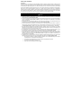
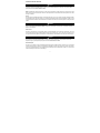
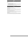
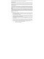
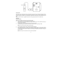
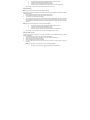
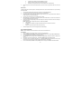
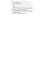
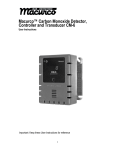
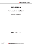
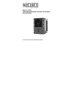
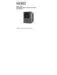
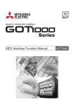
Macurco™ GD-12 Combustible Gas Detector, Controller and Transducer User Instructions Important: Keep these User Instructions for reference TABLE OF CONTENTS GENERAL SAFETY INFORMATION Intended Use List of Warnings and Cautions USE INSTRUCTIONS AND LIMITATIONS Use For Do Not Use For General Description Features Specifications INSTALLATION AND OPERATING INSTRUCTIONS Location Connections Installation 4-20 mA Output diagram Rear View Image Gas Valve Control diagram Multiple Device diagram Alternate Alarm Panel diagram DVP-120 Control Panel diagram Power Up Operation Default - Factory Settings Display setting Buzzer setting Alarm Relay setting Alarm Relay Configuration Fan Relay setting Fan Relay Delay setting Fan Minimum Runtime setting Fan Relay Latching setting Trouble Fan Setting 4-20mA Output setting On Board Diagnostics Sensor Poisons MAINTENANCE End-of-Life Signal Sensor Life Reset Cleaning Testing Operation Test Gas Test Quick Gas Test Field Calibration Procedure MACURCO GAS DETECTION PRODUCTS WARRANTY 3 3 3 4 4 4 4 5 5 5 6 6 7 8 8 8 9 9 10 10 10 10 11 12 12 12 12 12 13 13 13 13 13 14 12 14 14 14 15 16 17 17 21 22 2 GENERAL SAFETY INFORMATION Intended Use The Macurco GD-12 is a line voltage, dual relay Combustible Gas detector, controller and transducer. The GD-12 utilizes an internal switching power supply that is capable of using line voltage between 100 and 240VAC and 50-60Hz. The GD-12 has selectable 4-20 mA output, buzzer and digital display options. It is an electronic detection system used to measure the concentration of Combustible Gas and provide feedback and automatic exhaust fan, louver or valve control to help reduce gas concentrations in parking garages, battery rooms or other commercial applications. The GD-12 is a versatile, easy-to-use device that allows you to select between methane, propane or hydrogen gas detection. It provides low-level detection of combustible gas in an easy-to-maintain monitor that is factory calibrated for simple installation. The GD-12 is capable of displaying from 0-50% LEL (Lower Explosive Limit) of Combustible Gas. The GD-12 is factory calibrated and 100% tested for proper operation, but can also be calibrated in the field. List of Warnings and Cautions within these User Instructions ! WARNING Each person using this equipment must read and understand the information in these User Instructions before use. Use of this equipment by untrained or unqualified persons, or use that is not in accordance with these User Instructions, may adversely affect product performance and result in sickness or death. Use only for monitoring the gas which the sensor and instrument are designed to monitor. Failure to do so may result in exposures to gases not detectable and cause sickness or death. For proper use, see supervisor or User Instructions, or call Technical Service at 1-877-367-7891. This equipment may not function effectively below 0F or above 125F (-18C or above 52C). Using the detector outside of this temperature range may adversely affect product performance and result in sickness or death. This detector helps monitor for the presence and concentration level of a certain specified airborne gas. Misuse may produce an inaccurate reading, which means that higher levels of the gas being monitored may be present and could result in overexposure and cause sickness or death. For proper use, see supervisor or User Instructions, or call Technical Service at 1-877-367-7891. High voltage terminals (100-240VAC) are located within this detector, presenting a hazard to service technicians. Only qualified technicians should open the detector case and service the internal circuits. Ensure power is removed from the detector prior to servicing the unit. Failure to do so may result in sickness or death. Do not disassemble unit or attempt to repair or modify any component of this instrument. This instrument contains no user serviceable parts, and substitution of components may impair product performance and result in sickness or death. Using a certified gas with a concentration other than the one listed for this detector when conducting a calibration or calibration verification test (bump test) will produce inaccurate readings. This means that higher levels of the gas being monitored may be present and could result in overexposure and cause sickness or death. For proper use, see supervisor or User Instructions, or call Technical Service at 1-877-367-7891 The following steps must be performed when conducting a calibration or calibration verification test (bump test) to ensure proper performance of the monitor. Failure to do so may adversely affect product performance and result in sickness or death. When performing a calibration or calibration verification test (bump test) only use certified calibration gas at the required concentration level. Do not calibrate with expired calibration gas. If the instrument cannot be calibrated, do not use until the reason can be determined and corrected. Do not cover or obstruct display or visual alarm cover. Ensure sensor inlets are unobstructed and is free of debris 3 USE INSTRUCTIONS AND LIMITATIONS ! WARNING Each person using this equipment must read and understand the information in these User Instructions before use. Use of this equipment by untrained or unqualified persons, or use that is not in accordance with these User Instructions, may adversely affect product performance and result in sickness or death. NOTE: Combustible gas detectors will respond to a wide range of hydrocarbons, including aerosol sprays, cleaning solvents, paint thinner and other common household items. Be alert to other hydrocarbons near the detector before assuming that the unit is false alarming or is defective. Use For The GD-12 provides combustible gas detection and automatic exhaust fan, louver or valve control for automotive maintenance facilities, enclosed parking garages, utility rooms, battery rooms, warehouses with forklifts and other commercial applications. The GD-12 can be used stand alone, with the Macurco DVP-120 Detection and Ventilation Control Panel, other fire/security panels or building automation systems. ! WARNING Use only for monitoring the gas which the sensor and instrument are designed to monitor. Failure to do so may result in exposures to gases not detectable and cause sickness or death. For proper use, see supervisor or User Instructions, or call Macurco Technical Service at 1-877-367-7891. Do Not Use For The GD-12 is not intended for use in hazardous locations or industrial applications such as refineries, chemical plants, etc. Do not mount the GD-12 where the normal ambient temperature is below 0°F or exceeds 125°F (-18C or above 52C). The GD-12 mounts on a type 4S electrical box supplied by the contractor. Do not install the GD-12 inside another box unless it has good air flow through it. ! WARNING This equipment may not function effectively below 0F or above 125F (-18C or above 52C). Using the detector outside of this temperature range may adversely affect product performance and result in sickness or death. General Description The GD-12 is a line voltage, dual relay combustible gas detector and automatic ventilation controller. The GD-12 uses a microcomputer controlled, electronic system to measure the concentration of combustible gas, actuate relays and provide a 4-20 mA output. The GD12 has a low maintenance long life (5+ years) pellistor sensor and optional gas test and calibration kits. The GD-12 is a low level meter capable of displaying from 0-50% LEL of combustible gas. 4 Features ETL Listed to UL 61010-1 and CAN/CSA C22.2 No 61010-1 Low level meter capable of displaying from 0-50% LEL Selectable target gas – Methane(NG), Propane(LP) or Hydrogen(H2) Selectable fan and alarm relay activation 5 A SPDT fan relay controls starters of exhaust fans 0.5 A N.O. or N.C. alarm relay connects to warning devices or control panels 4-20 mA current loop GD-12 mounts on a standard 4x4 electrical box and becomes cover for the box Supervised system: any internal detector problem will cause the fan & alarm relay to activate Calibration kit is available. One screw allows access for calibration or gas test Specifications Power: 100-240VAC (50 TO 60 HZ) Current: 1.0 A MAX Shipping Weight: 1 pound (0.45 kg) Size: 4 1/2 x 4 x 2 3/4 in. (11.4 X 11.4 X 7.0 cm) Color: Dark gray Connections: plugs/terminals Mounting box: (not included) 4x4 electric Fan relay: 5 A, 240 VAC, pilot duty, SPDT, latching or non-latching Fan relay actuation: selectable at diS (disable) 3, 4, 5, 6, 7, 8, 9, 10 (default),11, 12, 13, 14, 15, 16, 17, 18, 19, 20% LEL Fan Delay Settings of 0, 1, 3 (default), 5 and 10 minutes Fan Minimum Run Time settings are 0 (default), 3, 5, 10 or 15 minutes Fan relay latching or not latching (default) selectable Alarm relay: 0.5A 120 V, 60 VA Alarm relay actuation: selectable N.O. default or N.C. Alarm relay settings: diS, 5, 10, 15, 20 (default), 25% LEL Current loop, 4-20 mA for 0-50% LEL, selectable to off or on (default) Buzzer: 85 dBA at 10cm settable to off (default) or on Digital display: 3 digit LED selectable to off (default) or on. Operating Environment: 0°F to 125°F (-18C to 52C).10 to 90% RH Operating altitude: Up to 5,000m (16,404ft) INSTALLATION AND OPERATING INSTRUCTIONS The following instructions are intended to serve as a guideline for the use of the Macurco GD-12 Combustible Gas Detector. It is not to be considered all-inclusive, nor is it intended to replace the policy and procedures for each facility. If you have any doubts about the applicability of the equipment to your situation, consult an industrial hygienist or call Technical Service at 1-877-367-7891. 5 ! WARNING This detector helps monitor for the presence and concentration level of a certain specified airborne gas. Misuse may produce an inaccurate reading, which means that higher levels of the gas being monitored may be present and could result in overexposure and cause sickness or death. For proper use, see supervisor or User Instructions, or call Technical Service at 1-877-367-7891. Location A GD-12 mounting height is dependent upon the target gas. If the target gas is lighter than air; methane (NG) or Hydrogen (H2), mount the GD-12 high on a wall or column (about one foot down from the ceiling) in a central area where air movement is generally good. If the target gas is heavier than air; propane (LP), mount the GD-12 low on a wall or column (about one foot above the floor) in a central area where air movement is generally good. The unit, on average, can cover about 900 sq. ft. (84 sq. meters). The coverage depends on air movement within the room or facility. Extra detectors may be needed near any areas where people work or where the air is stagnant. Do NOT mount the GD-12 where the normal ambient temperature is below below 0°F or exceeds 125°F (below -18C or above 52C). ! WARNING High voltage terminals (100-240VAC) are located within this detector, presenting a hazard to service technicians. Only qualified technicians should open the detector case and service the internal circuits. Ensure power is removed from the detector prior to servicing the unit. Failure to do so may result in sickness or death. General Wiring Information With the exception of the safety ground, all field wiring is completed via modular connectors (provided). After wiring, simply plug the modular connectors into the matching connectors on the back side of the detector. Mains Power Connection Mains connections should be done in accordance with National and Local Electrical Codes. Only qualified personnel should connect Mains power to any device. Macurco recommends a minimum wire size of AWG18 and the wire insulator must be rated for 140°F (60°C) service. The modular connector will accept wire from 12 to 24 AWG. The safety ground wire should be secured to the ground screw of the metal electrical box. Tighten the screw and make sure the wire is snug. Ensure that the wire cannot be pulled out from under the screw. The Line (L) and Neutral (N) wires should be stripped 1/4 in. (6.5 mm), insert the wire into the ”L” and “N” wire positions of the modular Fan/Power connector and tighten the screw clamp. Ensure that the wire cannot be easily pulled from the connector. Plug the modular connection into the Fan/Power connection and ensure that it latches into the header properly. Fan Relay Connection All of the SPDT Fan relay terminals are available at the Fan/Power modular connector. Each Fan relay terminal normally open, common and normally closed (NO, COM and NC) can accommodate a wire size 12 to 24 AWG. To install the wiring for the relays, disconnect the connector from the header. Strip the insulation of each wire back approximately 1/4 in. (6.5 mm), insert the bare wire 6 into the terminal and tighten the screw clamp. Ensure that the wire cannot easily be pulled from the connector. Plug the modular connection into the Fan/Power connection and ensure that it latches into the header properly. Alarm Relay Connection The external alarm connections (A and B) are available at the Alarm modular connector. There is no polarity for these connections. To install the wiring for the alarm contacts disconnect the connector from the header on the detector. Strip the insulation of each wire back approximately 1/4 in. (6.5 mm), insert the bare wire into the terminal and tighten the screw clamp. Ensure that the wire cannot easily be pulled from the connector. When the wires are connected seat the modular connector into the header ensuring that the latch engages. 4-20mA Signal Connection The positive and negative 4-20mA signal connections (+ and -) are available at the 4-20mA modular connector, a 2-position connector. To install the wiring for the 4-20 mA contacts disconnect the connector from the header on the detector. Strip the insulation of each wire back approximately 1/4 in. (6.5 mm), insert the bare wire into the terminal and tighten the screw clamp. Ensure that the wire cannot easily be pulled from the connector. When the wires are connected seat the modular connector into the header ensuring that the latch engages. NOTE: The 4-20mA current loop outputs may be used with the Macurco DVP-120 control panel or other systems. The 4-20mA signal connections to detectors should be size AWG18 (minimum) for short runs. Refer to the table for recommended wire gauges. Do not bundle detector 4-20mA signal connections with AC power cables to prevent electrical interference. If AC power connections must be bundled with the detector 4-20mA signal cables, the signal connections should be made with twisted pair of the appropriate gauge, with an overall foil and braid shield. All shields should be terminated at the DVP-120 end of the cable only. A ground stud is provided near the bottom left corner of the DVP-120 panel. Installation 1. The GD-12 mounts on a 4” square (or 4x4) electrical box supplied by the contractor. Do not mount the CM-6 inside another box, unless it has good air flow through it. 2. There are two terminals for the dry alarm relay contacts, again with no polarity preference. The alarm relay can switch up to 0.5 A 120 V, or 60 VA. The alarm relay is activated if gas reaches or exceeds the alarm settings. See OPERATION section of these User Instructions for details on relay settings. 3. The alarm relay can be configured to normally open (default) (N.O.) or normally closed (N.C.) and will activate if the gas concentration exceeds alarm set point. It will deactivate once the gas concentration drops below the alarm set point. Note that the “disable” setting will cause the alarm relay not to engage at all. 4. The dry contact, SPDT fan relay has three terminals. The common (COM.), normally open (N.O.) and the normally closed (N.C.) contact. The fan relay can switch up to 5.0 A up to 240 VAC. See OPERATION section of these User Instructions for details on relay settings. 5. The Fan Relay can be configured for latching or non-latching (default) when activated (when the gas concentration exceeds fan relay set point). Once latched in, power will need to be interrupted or the “TEST” button pressed to un-latch the relay condition. 6. The Fan Relay will engage if the fan setting Combustible Gas concentration is exceeded for longer than the Fan Relay Delay time. Unless it is configured for latching, the fan relay will disengage once both of these conditions have been met: Combustible Gas concentration has dropped below fan setting Fan Relay Run time has been exceeded 7 7. Note that the “disable” fan setting will cause the fan relay to not engage. The fan relay will engage in trouble fault condition (if the Trouble Fan Setting Option is set to “ON”) and will disengage once trouble fault condition is cleared. The Current Loop is 4 mA in clean air and 4-20 mA for 0-50% LEL 8 9 Typical connection to the Macurco DVP-120 Detection and Ventilation Control Panel Power Up The GD-12 cycles through an internal self-test cycle for the first minute that it is powered. The unit will execute the test cycle any time power is dropped and reapplied (i.e. power failure). During the self-test cycle the unit will display the firmware version number, then count down from 60 to 0 (if the display setting is “On”) and finally go into normal operation. The alarm relay will be activated for 10 seconds and the fan relay for 60 seconds during the power-up cycle unless the “Power Up Test” (PUt) option is OFF. The indicator light (LED) will flash green during the self-test cycle. At the end of the 1 minute cycle, the unit will take its first sample of the air and the indicator light will turn solid green. Operation 1. With the display function turned “On”, the GD-12 will show the current concentration of gas % LEL or “0” (zero) in clean air. When the gas concentration reaches the Fan Relay setting (10% LEL, for example) the display will flash back and forth between “FAn” and “10”. With the display function turned ”Off”, the display does not show the gas concentration, but will show “FAn” as long as the fan relay is activated. 2. With the display function turned “On” and the gas concentration reaching the alarm relay setting, (20% LEL, for example) the display will flash back and forth between “ALr” and “20”. The buzzer will sound indicating “Alarm” if the buzzer is turned “On”. With the display function turned off the display does not show the gas concentration, but will show “ALr” when the Alarm relay is activated. 3. With the 4-20 mA function turned “On”, the 4-20 mA output will correspond to the concentration (0-50% LEL). The display will show “FAn” and “ALr” and sound as outlined above. 10 Default Configuration – Factory Settings The default Gas setting is ME (methane) The default Power Up Test setting is On The default Display setting is Off The default Buzzer setting is Off The default Alarm Relay Setting is activation at 20% LEL The default Alarm Relay Configuration is Normally Open The default Fan Relay Setting is activation at 10% LEL The default Fan Relay Delay setting is 3 minutes The default Fan Relay Runtime setting is 0 The default Fan Relay Latching condition is OFF The default Trouble Fan Setting condition is OFF The default 4-20 mA Output setting is On To change settings, remove the Philips screw on the front of the GD-12. Pull off the front cover of the unit. Gas Selection To select the Gas Option, in normal mode, press the Next button once to display the current gas selection (mE is Methane, Pro is Propane and Hy is Hydrogen). Then press the Enter button twice to enter the selection menu. The currently selected gas will be shown on the display. Press Next to scroll through the available gases selections. The selected gas will be flashing, press Enter to select the gas and Enter again to confirm the selection. To return back to normal mode press Next until “End” is displayed and press Enter. Selecting Default Configuration – “dEF” 11 To select the Default Configuration, in normal mode, press the Next button twice to get to “Con” or the Configuration menu. Then press the Enter button to enter the Con menu. The first selection is the “dEF” or Default setting. Press Enter. If it is already in Default configuration, there will be no action. If it is not already in Default configuration, “nO” will be displayed. Press Next to change it to “YES” (flashing) then press Enter to confirm the change (solid) and press Enter again to return to “dEF” in the Con menu. Press Next until “End” is displayed then press Enter to return to normal operation. Selecting Power Up Test Option – “PUt” To select the Power Up Test Configuration, in normal mode, press the Next button twice to get to “Con” or the Configuration menu. Then press the Enter button to enter the Con menu. Then press the Next button to get to the second selection “PUt” or Power Up Test setting. Press Enter. If the test is “On” press Next to turn it “OFF” (flashing) then press Enter to confirm the change (solid) and press Enter again to return to “PUt” in the Con menu. Press Next until “End” is displayed then press Enter to return to normal operation. Selecting Display Option – “dSP” To select the Display Configuration, in normal mode, press the Next button twice to get to “Con” or the Configuration menu. Then press the Enter button to enter the Con menu. Then press the Next button twice to get to the third selection “dSP” or Display setting. Press Enter. If the display is “On” press Next to turn it “OFF” (flashing) then press Enter to confirm the change (solid) and press Enter again to return to “dSP” in the Con menu. Press Next until “End” is displayed then press Enter to return to normal operation. Selecting Buzzer Option – “bUZ” To select the Buzzer Configuration, in normal mode, press the Next button twice to get to “Con” or the Configuration menu. Then press the Enter button to enter the Con menu. The fourth selection is the “bUZ” or Buzzer setting. Press Next three times to get to “bUZ” then press Enter. If the display is “On” press Next to turn it “OFF” (flashing) then press Enter to confirm the change (solid) and press Enter again to return to “bUZ” in the Con menu. Press Next until “End” is displayed then press Enter to return to normal operation. Selecting Alarm Relay Setting – “ArS” To select the Alarm Relay Setting, in normal mode, press the Next button twice to get to “Con” or the Configuration menu. Then press the Enter button to enter the Con menu. The fifth selection is the “ArS” or Alarm Relay Setting. Press Next four times to get to “ArS” then press Enter. If the display is “OFF” (disabled) press Next to change it to 5, 10, 15, 20 or 25% LEL (flashing) then press Enter to confirm the change (solid) and press Enter again to return to “ArS” in the Con menu. Press Next until “End” is displayed then press Enter to return to normal operation. Selecting Alarm Relay Configuration – “Arc” To select the Alarm Relay Configuration, in normal mode, press the Next button twice to get to “Con” or the Configuration menu. Then press the Enter button to enter the Con menu. The sixth selection is the “Arc” or Alarm Relay Configuration. Press Next five times to get to “Arc” then press Enter. If the relay is “nO” (normally open) press Next to turn it to “nC” (flashing) then press Enter to confirm the change (solid) and press Enter again to return to “Arc” in the Con menu. Press Next until “End” is displayed then press Enter to return to normal operation. Selecting Fan Relay Settings – “FrS” To select the Fan Relay setting, in normal mode, press the Next button twice to get to “Con” or the Configuration menu. Then press the Enter button to enter the Con menu. The seventh selection is the “FrS” or Fan Relay setting. Press Next six times to get to “FrS” then press Enter. If the fan relay is “OFF” (disabled) press Next to change it to 3, 4, 5, 6, 7, 8, 9, 10, 11, 12, 13, 14, 15, 16, 17, 18, 19 or 20% LEL (flashing) then press Enter to confirm the change (solid) and press Enter again to return to “run” in the Con menu. Press Next until “End” is displayed then press Enter to return to normal operation. 12 Selecting Fan Relay Delay – “Frd” To select the Fan Relay Delay setting, in normal mode, press the Next button twice to get to “Con” or the Configuration menu. Then press the Enter button to enter the Con menu. The eighth selection is the “FrD” or Fan Relay Delay. Press Next seven times to get to “FrD” then press Enter. If the delay is “OFF” (disabled) press Next to change it to 1, 3, 5, or 10 minutes (flashing) then press Enter to confirm the change (solid) and press Enter again to return to “FrD” in the Con menu. Press Next until “End” is displayed then press Enter to return to normal operation. Selecting Fan Relay Run Time – “Frr” To select the Fan Minimum Runtime setting, in normal mode, press the Next button twice to get to “Con” or the Configuration menu. Then press the Enter button to enter the Con menu. The ninth selection is the “Frr” or Fan Minimum Run Time. Press Next eight times to get to “Frr” then press Enter. If the runtime is “OFF” (disabled) press Next to change it to 3, 5, 10 or 15 minutes (flashing) then press Enter to confirm the change (solid) and press Enter again to return to “run” in the Con menu. Press Next until “End” is displayed then press Enter to return to normal operation. Selecting Fan Relay Latching Option – “FrL” To select the Fan Relay Latching Option, in normal mode, push the Next button twice to get to “Con” or the Configuration menu. Then push the Enter button to enter the Con menu. The tenth selection is the “FrL” or Fan Relay Latching Option. Push Next nine times to get to “FrL” then Enter. If latching is “OFF” push Next to turn it to “ON” (flashing) then push Enter to confirm the change (solid) and push Enter again to return to “FrL” in the Con menu. Push Next until “End” is displayed then push Enter to get back to normal operation. Selecting Trouble Fan Setting Option – “tFS” To select the Trouble Fan Setting Option, in normal mode, push the Next button to get to “Con” or the Configuration menu. Then push the Enter button to enter the Con menu. The eleventh selection is the “tFS” or Trouble Fan Setting Option. Push Next ten times to get to “tFS” then Enter. If Trouble Fan Setting is “OFF” push Next to turn it to “ON” (flashing) then push Enter to confirm the change (solid) and push Enter again to return to “tFS” in the Con menu. Push Next until “End” is displayed then push Enter to get back to normal operation. Selecting 4-20 mA Output Option – “420” To select the 4-20 mA Output Option, in normal mode, press the Next button twice to get to “Con” or the Configuration menu. Then press the Enter button to enter the Con menu. The twelfth selection is the “420” or 4-20mA Output Option. Push Next eleven times to get to “420” then press Enter. If the 4-20 mA is “On” press Next to turn it to “OFF” (flashing) then press Enter to confirm the change (solid) and press Enter again to return to “420” in the Con menu. Press Next until “End” is displayed then press Enter to return to normal operation. Onboard Diagnostics The GD-12 monitors all critical functions of the unit through software diagnostics that continuously test and verify unit operations. If a problem is found, the unit will switch to a fail-safe/error mode or trouble condition. In this error mode, the Alarm relay will be activated, the 4-20 mA current loop will go to 24 mA, the unit will display the error code, the green status indicator LED light will flash and the buzzer will chirp intermittently. The Fan relay will also engage if the Trouble Fan Setting Option is set to “ON”. This is a safety 13 precaution. To clear this mode, simply turn off power to the unit for a few seconds, or push the ENTER/TEST switch (inside the unit). This will cause the unit to restart the 1 minute self-test cycle. The 4-20 mA signal can be used for troubleshooting: 0 mA is most likely a connection problem 4-20 mA is normal gas reading range (0-50% LEL) 24 mA indicates a Trouble condition Error Codes t01 t04 t08 t10 t20 t40 t80 t100 t200 Sensor missing EEPROM bad checksum Sensor is shorted Bad EEPROM Bad calibration Factory calibration failure Read ADC failure Under range Sensor expired NOTE: For trouble codes over 080 the display will alternate between t_1 and t00 for t100 and between t_2 and t00 for t200. If the error mode repeats frequently, check for continuous power and proper voltage. If power is not the problem and a unit has repeating error conditions, it may need to be returned to Macurco for service, per these User Instructions. If the error mode indicates “Sensor expired” see the Sensor Life Reset section of these User Instructions. Sensor Poisons The gas sensor in the detector is designed with extreme sensitivity to the environment. As a result, the sensing function may be deteriorated if it is exposed to silicones, such as the common oil and lubricants with silicon compounds used as additives in machinery, halogen compounds, which are used in fire extinguishers and Freon used in refrigerants, organo-metallic compounds, sulfur compounds, chlorine compounds, acetylene, olefins or high concentrations of combustible gas. MAINTENANCE The GD-12 is low maintenance. The unit uses a long life pellistor sensor that has a 5+ year life expectancy. The detector’s performance should be tested regularly by using gas as detailed in the Testing and Field Calibration sections. All other maintenance and repair of products manufactured by Macurco are to be performed at the appropriate Macurco manufacturing facility. Macurco does not sanction any third-party repair facilities. End-of-life Signal 14 The GD-12 has a long life, non-replaceable catalytic bead sensor. Five (5) years after the GD-12 is installed the sensor end-of-life signal will be activated indicating that the GD-12 has reached the end of its typical usable life. The end-of-life signal will cause an error code t200 “Sensor expired”. See Error Codes section. The end-of-life signal can be silenced for 48 hours by pressing the "ENTER/TEST" button or by temporarily dropping power to the unit. The end-of-life signal provides the user an opportunity to test and/or calibrate the sensor assuring that it is still performing within acceptable parameters though the sensor is nearing the end of its expected life. The silence function will continue to be available for 29 days after the GD-12 initiates the initial end-of-life signal. After this 29 day period the GD-12 can no longer be silenced and the sensor must be calibrated and the sensor life reset or the GD-12 detector replaced. Sensor Life Reset 1. Remove the Philips screw on the front of the GD-12. Pull the front cover of the unit off. 2. To reset the sensor life (rSt), from normal or warm-up mode, press the Next button five times to get to SEn or Sensor Mode. 3. Then press the Enter button to get to “rSt” - Reset Sensor Mode. 4. Press the Enter button again to see the sensor reset status. If the sensor life has already been reset, done “don” will be displayed. If it has not already been reset, “no” will be displayed. Push Next to change it to “ YES” (flashing) then push Enter to confirm the change (solid) and push Enter again to return to "rSt” in the SEn menu. Push Next until “End” is displayed then push Enter to get back to normal operation. The sensor life will be reset for 1 year. NOTE: If the sensor is reset and the detector not replaced it is necessary to test and/or calibrate the sensor to assure that it is still performing within acceptable specifications though the sensor is nearing the end of its expected life. There will be no other indication of sensor performance. ! WARNING Do not disassemble unit or attempt to repair or modify any component of this instrument. This instrument contains no user serviceable parts, and substitution of components may impair intrinsic safety, which may adversely affect product performance and result in sickness or death. CAUTION Avoid the use of harsh cleaning materials, abrasives and other organic solvents. Such materials may permanently scratch the surfaces and damage the display window, labels, sensor or instrument housing. Cleaning Cleaning of the external surfaces is best carried out using a damp cloth with a mild detergent or soap. Use a vacuum cleaner with soft brush to remove dust or contamination under the cover. Do not blow out the sensor with compressed air. TESTING ! WARNING Using a certified gas with a concentration other than the one listed for this detector when conducting a calibration or calibration verification test (bump test) will produce inaccurate readings. This means that higher levels of the gas being monitored may be present and could result in overexposure and cause sickness or death. For proper use, see supervisor or User Instructions, or call Technical Service at 1-877-367-7891 15 General All GD-12 units are factory calibrated and 100% tested for proper operation. During normal operation the green status indicator LED light will be on steady, the fan & alarm relay will be in standby mode and the 4-20 mA output will be at 4mA (in clean air).The unit also performs a regular automatic self-test during normal operation. If the unit detects an improper voltage or inoperable component, it will default into Error mode. In this error mode, the Alarm relay will be activated, the 4-20 mA current loop will go to 24 mA, the unit will display the error code, the green status indicator LED light will flash and the buzzer will chirp intermittently. The Fan relay will also engage if the Trouble Fan Setting Option is set to “ON”. Operation Test Check that the green GD-12 status indicator LED light is illuminated continuously. If not, do not proceed with the tests. If the unit is in error mode contact your local representative or Macurco technical service representative for information on resolving the problem. 1. Remove the single screw in the middle of the front cover of the GD-12. 2. Remove the front cover. 3. Observe the LED light on the front of the GD-12. 4. If the light is solid green proceed to step 6. 5. If the green status indicator LED light is off or flashing, refer to the General section above. 6. Locate the switch labeled ENTER/TEST on the left side of the printed circuit board. Press the Test switch once. 7. The GD-12 will step through a cycle test: a. The display progresses through the BUZ (Buzzer Test) Art (alarm relay test), Frt (fan relay test) then 42t (4-20 mA output test). Make sure that the settings are “on” or not disabled “diS”. b. During the first 10 seconds of the test cycle, the display will show BUZ and set off the audible buzzer c. The alarm relay will be closed, so any devices connected to that relay will be tested. d. The Fan relay will be activated for the next 1 minute of the test, so if the fan circuits are wired in the normal manner, the fan should run. e. The 4-20mA output will then ramp up from 4 to 16 mA over the next 130 seconds of the test, so if the circuit is wired in the normal manner, the control panel or building automation system should respond. f. At the end of the test cycle, the light will turn green and be on steady (Normal Operation), the fan & alarm relay will be in standby mode and the 4-20 mA output will return to 4 mA (in clean air). 8. When testing is completed reassemble the unit or units. Manual Operation Test This option gives the user the opportunity to manually initiate an individual test for each relay, the analog output and the sensor response to gas. From normal operation mode press the Next button 3 times to get to the Test Mode (tSt). Press the Enter button once to get into the Test Menu. Press the Next button to scroll through the four test options and press Enter to initiate the selected test. Note that if the relay or 4–20 mA output has been disabled, the test selection will not be displayed in the test menu. Art - Alarm Relay Test, 10 seconds Frt - Fan Relay Test, 60 seconds 16 42t - 420 loop test, 25 seconds gtS - Gas Test, 3 minutes (no output to the panel during the gas test) The display will flash during the test or in the case of the gas test the level will alternate with the expected gas (mE, Pro or Hy). Once the test is complete, the display will return to steady display. To exit the test menu, press the Next button until “End” is displayed, then press Enter to return to normal mode. Combustible Gas Gas Test ! WARNING The following steps must be performed when conducting a calibration or calibration verification test (bump test) to ensure proper performance of the monitor. Failure to do so may adversely affect product performance and result in sickness or death. When performing a calibration or calibration verification test (bump test) only use certified calibration gas at the required concentration level. Do not calibrate with expired calibration gas. If the instrument cannot be calibrated, do not use until the reason can be determined and corrected. Do not cover or obstruct display or visual alarm cover. Ensure sensor inlets are unobstructed and is free of debris General The GD-12 can be bump-tested or calibrated with the GD-12 Field Calibration Kit using Methane, Propane or Hydrogen gas, regulator and test hood, available through your local representative or from Macurco. Contents of the FCK GDM-FCK: Two Gas Cylinders, 10% LEL Methane gas in air, 20% LEL Methane in air, Gas regulator with two feet of plastic tubing, Humidifier and Gas test hood GDP-FCK: Two Gas Cylinders, 10% LEL Propane gas in air, 20% LEL Propane in air, Gas regulator with two feet of plastic tubing, Humidifier and Gas test hood GDH-FCK: Two Gas Cylinders, 10% LEL Hydrogen gas in air, 20% LEL Hydrogen in air, Gas regulator with two feet of plastic tubing, Humidifier and Gas test hood 17 FCK Information Several detectors can be calibrated with one FCK. The only limitation is the amount of gas in the cylinder and the flow of the regulator. The 34 liter cylinder for example with a 0.2LPM regulator has approximately 170 minutes of continuous calibration run time. Replacement cylinders are available. The gas cylinder should be replaced when the pressure gauge on the regulator shows 25-psi or less. NOTE: For optimum test results it is suggested that the unit be in clean air (green light on) and be in a low ambient air flow Gas Testing Testing the Fan Relay NOTE: The gas concentration to activate the fan relay depends on the setting. 1. Remove the Philips screw on the front of the GD-12. Remove the front cover. 2. Connect the 10% LEL cylinder of Combustible Gas to the regulator. Ensure that the gas used for calibration matches the gas selected in the GD-12 configuration. 3. Assemble regulator, hose and test hood and place the test hood over the gas sensor. 4. Check the pressure gauge on the regulator. If you have 25-psi or less you will need to replace the gas canister. NOTE: The time to activate the fan relay depends on the delay setting. 5. 6. Turn on the regulator to start the gas flow and wait with the gas applied continuously. With the display function turned “On”, the GD-12 will show the current concentration of gas or “0” (zero) in clean air. When the gas concentration reaches the fan relay setting (5% LEL, for example) the display will flash back and forth between “FAn” and “5”. With the display function turned ”Off”, the display does not show the gas concentration, but will show “FAn” as long as the fan relay is activated. NOTE: If the Fan relay does not close within 2 minutes, consider these possibilities: 18 a. b. c. d. 7. Gas cylinder is empty, check the pressure gauge. Replace the gas cylinder if 25-psi or less. Unit needs to be re-calibrated (go through recalibration and re-test). Detector is in need of servicing (return unit to factory for servicing). Detector has fan relay set to disable (OFF) or 20% LEL. Set fan relay to 5% LEL and repeat the test. Remove the gas from the sensor. Proceed to test the alarm relay or replace the top cover. Testing the Alarm Relay NOTE: The gas concentration to activate the Alarm relay depends on the setting. Connect the 20% LEL cylinder of Combustible Gas to the regulator. Ensure that the gas used for calibration matches the gas selected in the GD-12 configuration. 1. Check the pressure gauge. If there is 25-psi or less the cylinder should be replaced. 2. Place the test hood over the gas sensor. Turn on the regulator to start the gas flow. 3. The Fan relay should activate according to the settings. 4. With the display function turned “On” and the gas concentration reaching the Alarm Relay setting, (20% LEL, for example) the display will flash back and forth between “ALr” and “20”. The buzzer will sound indicating “Alarm” if the buzzer is turned “On”. With the display function turned off the display does not show the gas concentration, but will show “ALr” when the Alarm relay is activated. NOTE: If the Alarm relay fails to operate within 2 minutes, consider these possibilities: a. b. c. d. 5. Gas cylinder is empty, check the pressure gauge. Replace the gas cylinder if 25-psi or less. Unit needs to be re-calibrated (go through recalibration and re-test). Detector is in need of servicing (return unit to factory for servicing). Detector has Alarm relay set to disable (OFF). Set Alarm relay to 20% LEL and repeat the test. Remove the gas from the sensor after test. Proceed to test the 4-20 mA output or replace the top cover. Testing the 4-20 mA current loop Connect the 20% LEL cylinder of Combustible Gas to the regulator. Ensure that the gas used for calibration matches the gas selected in the GD-12 configuration. 1. Check the pressure gauge. If there is 25-psi or less the cylinder should be replaced. 2. Place the test hood from the regulator over the gas sensor. Turn on the regulator to start the gas flow. 3. The fan relay should activate according to the settings. 4. The alarm relay should activate according to the settings. 5. The 4-20 mA output should ramp up from 4mA in clean air to 20 mA at 50% LEL. See 4-20 mA diagram in these User Instructions. NOTE: If the 4-20mA output does not ramp up within 2 minutes, consider these possibilities: a. Gas cylinder is empty, check the pressure gauge. Replace the gas cylinder if 25-psi or less. 19 b. c. d. 6. Unit needs to be re-calibrated (go through recalibration and re-test). Detector is in need of servicing (return unit to factory for servicing). Detector has 4-20 mA option set to “OFF”. Set 4-20 mA option to “On” and repeat the test. Remove the gas from the sensor. Re-assemble the GD-12 (make sure the LED is aligned with the hole on the front of the case). Quick Gas Test A butane cigarette lighter can be used to perform a functionality test of the GD-12. This test allows installers to do a quick functionality test of the gas sensor. 1. 2. 3. 6. Units to be tested must be powered continuously for a minimum of 3 minutes before proceeding. For optimum test results, the unit should be in clean air and be in a low ambient air flow. Check that the GD-12 status indicator light is illuminated, green continuously. If not, do not proceed with tests. See GD-12 Trouble Indicator section in these User Instructions. The display option should be set to “On” and reading 0% LEL in clean air. With the CM-6 cover on, aim the lighter into the sensor grate area (under “DO NOT PAINT”) on the front cover and release the gas (without igniting the flame) for 1 second or less. Wait for a few seconds. The digital display should climb indicating the increased gas concentration at the sensor confirming a pass of the quick test. NOTE: If the Display does not change within 10 seconds, consider these possibilities: a. Lighter is empty. b. Unit needs to be re-calibrated (go through the Field Calibration Procedure in these User Instructions and re-test). c. Detector is in need of servicing (return unit to factory for servicing). 7. Wait for the display to return to 0% LEL and configure options to desired settings. 4. 5. FIELD CALIBRATION PROCEDURE NOTE: For optimum calibration results the unit should be in clean air and be in a low ambient air flow. Zero the Sensor 1. Remove the Philips screw on the front of the GD-12. Pull the front cover of the unit off. 2. To select Calibration Zero Mode (000), from normal mode, press the Next button four times to get to CAL or Calibration Mode. 3. Then press the Enter button to get to “000” - Calibration Zero Mode. 4. Press the Enter button and the display will read 0 alternating with 000 (blinking) indicating zero calibration in progress (max 165 sec). 5. If the process is successful, the display will read __0 alternating with PAS (blinking) Zero Calibration complete. 6. If the process was not successful the display will read __1 alternating with Fail (blinking) Zero Failed. If this occurs, repeat steps 2 through 4. If the sensor fails to zero twice contact Technical Assistance: 1-877-367-7891. 7. To return to Normal Mode press Enter and then press Next until “End” is displayed. Press Enter to return to Normal Mode. 20 Calibration 1. Remove the Philips screw on the front of the GD-12. Pull the front cover of the unit off. 2. Assemble the 10% LEL gas cylinder and regulator together. Ensure that the gas used for calibration matches the gas that the GD-12 is configured to (mE, Pro or Hy). 3. Check the pressure gauge on the regulator. If you have 25-psi or less you will need to replace the gas canister. 4. Place the test Hood from the regulator over the gas sensor. 5. To select Calibration Span Mode (SPn), from normal mode, press the Next button four times to get to CAL or Calibration Mode. 6. Then press the Enter button to get to “000” Calibration Zero Mode, then press the Next button to get to “SPn” – Calibration Span Mode. 7. Press the Enter button and the display will read 10 alternating with the gas, mE, Pro or Hy (blinking), indicating the sensor is looking for gas. 8. Start applying gas to the gas sensor. NOTE: The sensor will look for the gas for 45 seconds. If no gas is applied or detected in that time, the display will return to CAL. 9. When the sensor detects the gas, the display will flash back and forth between the gas concentration and SPn and the calibration will progress. The display will show this for a maximum of 165 seconds. 10. When the calibration is successful, the display will flash back and forth between 10 and PAS. 11. Remove the gas. The display will return to “SPn”, then normal mode. The calibration is done. 12. If the calibration fails, the display will flash back and forth between the gas concentration and FAL (fail). If this occurs, check the pressure gauge on the regulator. If the pressure is less than 25-psi the flow of gas may not be adequate to properly calibrate the unit. If there is proper pressure in the cylinder repeat steps 4 through 11. If the unit fails to calibrate twice contact Macurco Technical Assistance at 1-877-367-7891. 13. Disassemble the cylinder and regulator. 14. Re-assemble the GD-12 (make sure the LED is aligned with the hole in the front case). 15. See Calibration Flowchart on the inside of the housing. 21 MACURCO FIXED GAS DETECTION PRODUCTS LIMITED WARRANTY Macurco warrants the GD-12 gas detector will be free from defective materials and workmanship for a period of two (2) years from date of manufacture (indicated on the inside cover of the GD-12), provided it is maintained and used in accordance with Macurco instructions and/or recommendations. If any component becomes defective during the warranty period, it will be replaced or repaired free of charge, if the unit is returned in accordance with the instructions below. This warranty does not apply to units that have been altered or had repair attempted, or that have been subjected to abuse, accidental or otherwise. The above warranty is in lieu of all other express warranties, obligations or liabilities. THE IMPLIED WARRANTIES OF MERCHANTABILITY AND FITNESS FOR PARTICULAR PURPOSE ARE LIMITED TO A PERIOD OF TWO (2) YEARS FROM THE PURCHASE DATE. Macurco shall not be liable for any incidental or consequential damages for breach of this or any other warranty, express or implied, arising out of or related to the use of said gas detector. Manufacturer or its agent’s liability shall be limited to replacement or repair as set forth above. Buyer’s sole and exclusive remedies are return of the goods and repayment of the price, or repair and replacement of non-conforming goods or parts. Manufactured by Aerionics, Inc. Sioux Falls, SD Email: [email protected] Phone: 1-877-367-7891 Rev 08.19.2014 © Aerionics 2014. All rights reserved. Macurco is a trademark of Aerionics, Inc. 22