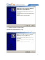
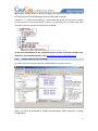
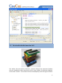
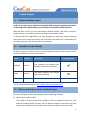
1
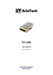
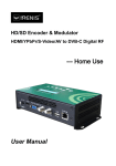
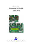
Cookie User Manual For NuMicro Edition 1.0 Rev. 1.0 Website: http://www.coocox.org Forum: http://forum.coocox.org Technical: [email protected] Market: [email protected] Release: 2012-08-09 1 Introduction Cookie is an open-source Arduino-compatible ARM prototyping platform based on 32-bit ARM Cortex M0/3/4 MCUs plus hardware and software building blocks. Cookie expands the concepts of Arduino into 32-bit ARM Cortex MCUs. Different types of 32-bit ARM Cortex M0/M3/M4 MCUs can be selected and switched freely because of CooCox CoX Peripheral Interface. CooCox CoX Peripheral Interface, a unified peripheral interface, makes it easy to reuse Arduino Shields across different Cookie boards. CooCox also provides a complete tool kit including IDE, Flash Program, Graphical pin configuration, and code generation tool, etc. The CooCox Component Platform also makes it easy to share code. The NuMicro edition of Cookie has been added into CooCox and will be released soon. As the next step, we will work on the ST edition, the TI edition, etc. of Cookie, as shown on our schedule on the Cookie’s homepage: http://www.coocox.org/Cookie.html. 2 Features Hardware CAD design files open under CC BY-SA 3.0 license in Eagle format. Fully compatible with Arduino, hundreds of Shields can be reused. Types of 32-bit ARM Cortex MCUs available (M0/M3/M4). Working on both 3.3V and 5V, selectable with jumper. CoLinkEx (USB-JTAG/SW debug probe) onboard, Debug IN/OUT selectable with jumper. A set of free development tools provided by CooCox. Component platform makes it easy to share code. 2 3 Cookie NuMicro The Cookie NuMicro edition is based on the Nuvoton Cortex M0 microcontroller M0516LBN. The M0516LBN with Cortex-M0 core can run up to 50MHZ, with 64KB Flash for program memory, 4KB Flash for data memory, 4KB SRAM, 2 UARTs, 2 SPIs, and 1 I2C. See data sheet: http://download.nuvoton.com/NuvotonMOSS/DownloadService/Member/Documen tsInfo.aspx?tp_GUID=DA00-M058/516 The Cookie NuMicro edition is fully compatible with Arduino, with 14 digital input/output pins (of which 6 can be used as PWM outputs), 6 analog inputs, a power jack, an ICSP header. It contains everything needed to support the microcontroller. There is also a CoLinkEx onboard to support program and debug. Simply connect it to a computer with a USB cable or power it with an AC-to-DC adapter or battery to get started. As Cookie is an open-source platform, all the documents and sources are free for download. You can find the Schematic, BSP Code, and also the PCB file on our website, http://www.coocox.org/Cookie/Cookie_Nuvoton.html. 3 4 Board Details 4.1 Block Diagram 4.2 Power Like the Arduino, The Cookie NuMicro edition can be powered via the USB connection or with an external power supply. The power source is selected automatically. External (non-USB) power can come from an AC-to-DC adapter (wall-wart) or a battery. The adapter can be connected by plugging a 2.1mm center-positive plug into the board's power jack. Leads from a battery can be inserted in the GND and Vin pin headers of the POWER connector. The board can operate on an external supply of 6 to 20 volts. If supplied with less than 7V, however, the 5V pin may supply less than five volts and the board may be unstable. If using more than 12V, the voltage regulator may overheat and damage the board. The recommended range is 7 to 12 volts. Note: The Board can be powered by 3V3, or 5V, if working with other shields, please check which power should be used. This can be switched by JP3. 4 The power pins are listed as follows: VIN. The input voltage to the board when it's using an external power source (as opposed to 5 volts from the USB connection or other regulated power source). You can supply voltage through this pin, or, if supplying voltage via the power jack, access it through this pin. 5V. This pin outputs a regulated 5V from the regulator on the board. The board can be supplied with power either from the DC power jack (7-12V), the USB connector (5V), or from the VIN pin of the board (7-12V). Supplying voltage via the 5V or 3.3V pins bypasses the regulator, and can damage your board. We don't advise it. 3V3. A 3.3 volt supply generated by the on-board regulator. GND. Ground pins. 4.3 Microcontroller The Cookie uses a Nuvoton M0516LBN as the main microcontroller. The NuMicro M0516LBN is a 32-bit microcontroller with embedded ARM Cortex-M0 core for industrial control and applications which need rich communication interfaces. The Cortex-M0 is the newest ARM embedded processor with 32-bit performance at a cost equivalent to traditional 8-bit microcontroller. 32-bit with ARM Cortex-M0 core running at up to 50MHz. 64KB Flash for programming, 4KB SRAM, 4KB Flash for data memory, 4KB Flash for boot loader. Built-in LDO for Wide Operating Voltage Range: 2.5V to 5.5V. Up to 40 GPIO Pins with LQFP-48 package. 2 UARTs, 2 SPIs, 1 I2C, 4-channel 32-bit timer, 1 watchdog timer, up to 4 16-bit PWM generators with 8 PWM outputs, and 12bit SRC ADC up to 8 analog inputs. 4.4 IO Each of the 14 digital pins on the Cookie can be used as an input or output or hardware peripheral function. The operate volt is determined by the JP1 (Board Power select), can be 3.3V or 5V. Pin Map: 5 Arduino Pin Arduino P Function MCU IO Map MCU Peripheral Function D0 UART.RX PA1 UART1.RTS/UART1.RX D1 UART.TX PA0 UART1.CTS/UART1.TX D2 EXT.INT PE0 PWM0/T2.EX D3 EXT.INT / PWM PE1 PWM1/T3.EX PE2 PWM2 D4 D5 PWM PE3 PWM3 D6 PWM PC4 PWM4 D7 PD2 NINT0/T0.EX D8 PD3 NINT1/T1.EX D9 PWM PC5 PWM5 D10 SPI.CS PA4 SPI1.CS PWM PC6 PWM6/CMP1.O SPI.MOSI PA5 SPI1.MOSI PWM PC7 PWM7 D12 SPI.MISO PA6 SPI1.MISO D13 SPI.CLK PA7 SPI1.CLK D11 AREF NC SDA I2C.SDA PD4 TIMCCP0/I2C0.SDA SCL I2C.SCL PD5 TIMCCP0/I2C0.SCK 6 A0 AIN PB0 ADC0/TIMCCP2 A1 AIN PB1 ADC1/TIMCCP3 A2 AIN PB2 ADC2/UART1RX A3 AIN PB3 ADC3/UART1TX A4 AIN PB4 ADC4/SPI0.CS/CMP0N I2C.SDA PD4 TIMCCP0/I2C0.SDA AIN PB5 ADC5/SPI0.MOSI/CMP0P I2C.SCL PD5 TIMCCP1/I2C0.SCK ICSP.1 SPI.MISO PB6 ADC6/SPI0.MISO ICSP.3 SPI.SCK PB7 ADC7/SPIO.CLK ICSP.4 SPI.MOSI PB5 ADC5/SPI0.MOSI/CMP0P A5 4.5 Communication Interface Port Signal Digital IO SPI SPI1 SS D10 MOSI D11 MISO D12 CLK D13 MOSI ICSP.4 MISO ICSP.1 SPI0 7 UART UART1 CLK ICSP.3 RX D0 TX D1 UART0 I2C I2C0 UART Debug SDA SDA / A4 SCL SCL / A5 4.6 Jumper Setting 4.6.1 Power Jumper or Button Description JP1 Power is 3V3 Power is 5V RST2 Reset M0516 4.6.2 Debug Jumper or Button Description JP2 Upgrade CoLinkEx 8 JP3 Connect J1.1(JTAG/SWD.VCC) with 3V3 JP4 Debug In / MCU JP5 Debug Output RST1 Reset CoLinkEx 4.6.3 Digital Jumper Description D10 SPI1.SS PWM6 D11 SPI1.MOSI PWM7 4.6.4 Analog Jumper Description A4 AIN4(ADC4) 9 I2C0.SDA A5 AIN5(ADC5) I2C0.SCL 5 Getting Start 5.1 Program & Debug The Cookie integrates a CoLinkEx on board. You can use the CoLinkEx to program and debug the Cookie MCU M0516, or program and debug other boards after setting debugging output through J1. The J1 (Debug In/Out Connect) signal details: 5.1.1 Install How to install the driver for the onboard CoLinkEx: You need to select the version of CoLinkEx USB Driver according to your Windows OS. The newest version of CoLinkEx driver can be downloaded from CooCox. See: http://www.coocox.org/Colinkex.htm 1) 32 bit windows system, for example: Windows XP/Windows Vista 32bit/Windows 7 32bit. Installation file: CoLinkExUsbDriver-1.1.0.exe 10 2) Windows Vista 64bit or Windows 7 64bit. Installation file: ColinkExUsbDriver-1.2.1.exe Please connect CoLinkEx to the computer before you start installing this driver. 11 When you install the driver, in device manager, you will found CooCox(COM x)under Port and CooCox CoLinkEx Debug Interface under USB Controller. If there is “?” in front of the devices, it means that the driver has not been installed on the system or install has failed; if there isn’t CooCox Port, it means that your CoLinkEx firmware and driver could be out of dated. To get more information of the onboard CoLinkEx, please check the CoLinkEx User manual or visit CoLinkEx website. See: http://www.coocox.org/Colinkex.htm 5.1.2 Using CoIDE to build and debug In CoIDE, you need to select Nuvoton, M0516LBN to start your project. When you want to download or debug the M0516LBN, Select CoLinkEx in Debug Configuration. 12 Then you can debug your project. 13 5.2 Work with shields based on CoX The Cookie, like the Arduino, features a common footprint for expansion headers that are intended to allow connectivity with a large number of expansion daughter cards called "shields". The shields have been developed by both the original Arduino 14 team and the community. These shields provide users with the ability to explore different technologies from a common and familiar environment such as motor control, advanced communications such as Ethernet, Wireless connectivity, and many more. CoX Peripheral Library is the definition of a group of interface functions. It defines the functional access functions of MCU’s common peripherals, such as IIC, SPI, UART, etc. CoX makes full functions, drivers based on CoX that can be ported to other MCU easily. Here, we use the CoX as the base library of Cookie: Free and open source under BSD license Peripherals’ library with an unified standard interface, can be ported to other MCUs easily Full functions of the peripheral, CoX still provides a set of APIs for special MCU features Supporting interrupt as CoX extracts a set of interrupt events A lot of reused drivers Extensive documentations generated using doxygen standard Standard definition of the API reference for almost all the Cortex-M0/M3 MCU manuals Adding a new innovative element, such as the short pin (PA2) in GPIO module Strict coding standard that does not affect code size and speed, through rigorous testing and verification Like the shield for the hardware building blocks, CoX and the drivers based on CoX are the software building blocks. You can develop the driver of a shield based on the CoX interface. Then the shield can be used in different editions of Cookie, such as NuMicro edtion or STM32 edition. Note: Please set the appropriate board power (3.3V / 5V) first according the shield you use. 15 6 Cookie Project 6.1 What is Cookie Project Cookie is an open-source Arduino-compatible ARM prototyping platform based on 32-bit ARM Cortex M0/3/4 MCU, plus hardware and software building blocks. What we want to do is to use Cookie board, Arduino Shields, CoX Library to build a Cookie Project, or an Arduino project on ARM Cortex M series’ MCU. To demonstrate the applications, we have designed an automatic system watering the flowers with remote monitoring. We will make more effort on it and build more interesting projects. We welcome you to participate. 6.2 Available Cookie Shields To do the project, we also need to use some Arduino shields. Here listed are some Arduino shields that you may interested in. Name Producer Description LCD1602 CooCox The character LCD module uses HD1602 as the main controller. Motor CooCox The Motor Module uses LQ134 to drive the E-Motor. CoX Supported You can download the code on http://www.coocox.org/driver.html 6.3 How to participate in the Cookie Project You can participate in the Cookie project via the following methods: 1) Upload your code in CoIDE The CoIDE 1.5.0 gives us the driver platform. You can upload the driver for your Arduino shields through this way. You can add the shields to the device list then upload the related driver. So all the person who use CoIDE will see your code. 16 2) Contribute through Github We will build some interesting projects on Github, and you can join us in those projects. All the shields that may be used in those projects can be bought through CooCox. You can also create a project using the shields at hands and commit it to our project. 3) E-mail your project to us If you already make a project and transplant it to CoX, you can send the project to us by E-mail. We will select the good projects to post on our website and blog. Then you can share your idea with everyone. 17