1
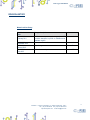
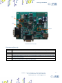
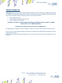
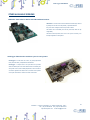
CAN Logger USER MANUAL Rel. 01.00.0002 (Hardware code: CAN LOG-SD, CAN LOG-F) 1 www.ipses.com CAN Logger USER MANUAL _____________________________ Information provided in this manual is property of IPSES S.r.l. and must be considered and treated as confidential. This publication can only be reproduced, transmitted, transcribed or translated into any human or computer language with the written consent of IPSES S.r.l. Information in this documentation has been carefully checked and is believed to be accurate as of the date of publication; however, no responsibility is assumed of inaccuracies. IPSES will not be liable for any consequential or incidental damages arising from reliance on the accuracy of this documentation. Information contained in this manual is subject to change without notice and does not represent a commitment on the part of IPSES. The design of this instrument is subject to continue development and improvement. Consequently, the equipment associated to this document may incorporate minor changes in detail from the information hereafter provided. All brand or product names are trademarks or registered trademarks of their respective holders. This manual in English is the original version. Printed in Italy Copyright 2009-2015IPSES S.r.l. All rights reserved. 2 IPSES S.r.l. Via Suor Lazzarotto, 10 - 20020 Cesate (MI) - ITALY Tel. (+39) 02 39449519 Fax (+39) 02 700403170 http://www.ipses.com e-mail [email protected] CAN Logger USER MANUAL GUARANTEE IPSES warrants to the end-user in accordance with the following provisions that its branded hardware products, purchased by the end-user from IPSES company or an authorized IPSES distributor will be free from defects in materials, workmanship and design affecting normal use, for a period of one year as of the original purchase date. Products for which proper claims are made will, at IPSES’s option, be repaired or replaced at IPSES’s expense1. Exclusions This Guarantee does not apply to defects resulting from: improper or inadequate installation, use or maintenance; actions or modifications by unauthorized third parties or the end-user; accidental or wilful damage or normal wear and tear. Making a claim Claims must be made by contacting IPSES office within the guarantee period. Please, contact: IPSES S.r.l. - Via Suor Lazzarotto, 10 - 20020 Cesate (MI) Italy Tel. (+39) 02 39449519 – (+39) 02 320629547 Fax (+39) 02 700403170 http://www.ipses.com - e-mail: [email protected] Limitation and Statutory Rights IPSES makes no other warranty, guarantee or like statement other than as explicitly stated above and this Guarantee is given in place of all other guarantees whatsoever, to the fullest extent permitted by law. In the absence of applicable legislation, this Guarantee will be the end-user’s sole and exclusive remedy against IPSES. General Provisions IPSES makes no express warranties or conditions beyond those stated in this warranty statement. IPSES disclaims all other warranties and conditions, express or implied, including without limitation implied warranties and conditions of merchantability and fitness for a particular purpose. IPSES’s responsibility for malfunctions and defects in hardware is limited to repair and replacement as set forth in this warranty statement. IPSES does not accept liability beyond the remedies set forth in this warranty statement or liability for incidental or consequential damages, including without limitation any liability for products not being available for use or for lost data or software. 1 With the exclusion of shipping costs for and from IPSES’s development office. 3 IPSES S.r.l. Via Suor Lazzarotto, 10 - 20020 Cesate (MI) - ITALY Tel. (+39) 02 39449519 Fax (+39) 02 700403170 http://www.ipses.com e-mail [email protected] CAN Logger USER MANUAL WARNING! ELECTRICAL DEVICES COULD DAMAGE EQUIPMENT OR PROPERTY OR CAUSE PERSONAL INJURY This guide contains instructions and technical features of the CAN Logger. Read with attention before attempting to install. It is the responsibility of the technician to undertake all the safety rules provided by the law during the installation and the use of this device. For any information which is not contained in this guide, please contact: IPSES S.r.l. - Via Suor Lazzarotto, 10 - 20020 Cesate (MI) Italy Tel. (+39) 02 39449519 – (+39) 02 320629547 Fax (+39) 02 700403170 http://www.ipses.com - e-mail: [email protected] 4 IPSES S.r.l. Via Suor Lazzarotto, 10 - 20020 Cesate (MI) - ITALY Tel. (+39) 02 39449519 Fax (+39) 02 700403170 http://www.ipses.com e-mail [email protected] CAN Logger USER MANUAL TABLE OF CONTENTS REVISION HISTORY .......................................................................................................................................................... 6 GENERAL FEATURES ....................................................................................................................................................... 7 CARD DESCRIPTION ........................................................................................................................................................ 8 STATUS LEDS.................................................................................................................................................................. 10 RS232 PINOUT................................................................................................................................................................. 10 CAN PINOUT .................................................................................................................................................................... 10 CAN BUS CONNECTION ................................................................................................................................................. 12 DRIVER INSTALLATION .................................................................................................................................................. 13 SOFTWARE ...................................................................................................................................................................... 16 STAND ALONE MODE ..................................................................................................................................................... 19 FIRMWARE UPGRADE FUNCTIONALITY ...................................................................................................................... 20 PRODUCT CODE ............................................................................................................................................................. 21 TECHNICAL FEATURES .................................................................................................................................................. 21 OTHER AVAILABLE VERSIONS ...................................................................................................................................... 22 CONTACTS ...................................................................................................................................................................... 24 SUPPORT INFORMATION ............................................................................................................................................... 25 PROBLEM REPORT......................................................................................................................................................... 25 ENGINEERING PROBLEM REPORT............................................................................................................................... 26 5 IPSES S.r.l. Via Suor Lazzarotto, 10 - 20020 Cesate (MI) - ITALY Tel. (+39) 02 39449519 Fax (+39) 02 700403170 http://www.ipses.com e-mail [email protected] CAN Logger USER MANUAL REVISION HISTORY Manual revision history Revision/ Date 01.01.0000 February 2011 01.00.0000 September 2010 01.00.0001 January 2012 01.00.0002 June 2015 Change description Author Modified external power supply voltage, added USB Zancanato A. connector description in picture 1a. Modified driver installation section. First version Released Zancanato A. Minor changes Mancuso C. Update document layout Bottaccioli M. 6 IPSES S.r.l. Via Suor Lazzarotto, 10 - 20020 Cesate (MI) - ITALY Tel. (+39) 02 39449519 Fax (+39) 02 700403170 http://www.ipses.com e-mail [email protected] CAN Logger USER MANUAL GENERAL FEATURES CAN Logger is a device especially conceived (in both versions SD and Flash) to store all the messages received from a CAN bus on a board memory, SD or Flash, depending on the purchased model. The card can work as stand-alone device on CAN bus. Its configuration is achieved either through USB (in this case the board is self powered) or through RS232 interface. The card is available in two models: CAN Logger-SD and CAN Logger Flash. The CAN Logger-SD model can save a log file directly in text format on a MicroSD card formatted as FAT32, while CAN Logger Flash uses an inner flash memory that can be read with the software provided with. A driver for USB is provided with the card. Besides, a configuration software is also provided with: this software allows to control the board either through USB and RS232, allows to configure CAN working parameters (such as baudrate, high and low speed, etc...), and also to configure filters on messages to be received and stored. 7 IPSES S.r.l. Via Suor Lazzarotto, 10 - 20020 Cesate (MI) - ITALY Tel. (+39) 02 39449519 Fax (+39) 02 700403170 http://www.ipses.com e-mail [email protected] CAN Logger USER MANUAL CARD DESCRIPTION CAN Logger card is shown in the pictures below. CAN, USB, RS232, external supply connectors, MicroSD connector (only for CAN Logger SD) and LED are also shown. ATTENTION: IN ORDER TO PRECLUDE MALFUNCTIONING OR DAMAGE DO NOT CONNECT EXTERNAL POWER SUPPLY AND USB AT THE SAME TIME ATTENTION: TO USE CAN LOGGER BOARD microSD CARD MUST BE INSERTED micro-SD POWER SUPPLY FOR STAND ALONE MODE OR RS232 MODE POWER SUPPLY FOR TRANSCEIVER CAN ISOLATION (OPTOISOLATED CONFIGURATION) STATUS LED USB 5V OUT CAN LINK LED USB L1, L2, L3, L4 L5, L7,L8 RS232 Picture 1a: CAN LOG card, LED and interfaces The LEDs are (Picture 1a): LINK STATUS L1 L2 L3 L4 L5 Green LED: USB has been recognized and can communicate Green LED: CAN enabled Red LED: RS232 enabled (if it is off ,USB is enabled) Red LED: reserved Red LED: reserved Red LED: Device in standalone mode Red LED: Memory full or error while saving 8 IPSES S.r.l. Via Suor Lazzarotto, 10 - 20020 Cesate (MI) - ITALY Tel. (+39) 02 39449519 Fax (+39) 02 700403170 http://www.ipses.com e-mail [email protected] CAN Logger USER MANUAL L7 L8 Red LED: firmware update mode (Only CAN Logger-Flash) Red LED: checking transceiver CAN 9 IPSES S.r.l. Via Suor Lazzarotto, 10 - 20020 Cesate (MI) - ITALY Tel. (+39) 02 39449519 Fax (+39) 02 700403170 http://www.ipses.com e-mail [email protected] CAN Logger USER MANUAL STATUS LEDS LED STATUS OFF ON Status description CAN in SLEEP mode CAN enable LED L4 Descrizione Stato CAN Logger in communication and configuration mode with PC CAN Logger in standalone mode LED L5 Descrizione Stato Recording memory NOT full Recording memory full or error while saving LED L8 Status description Device ready for use transceiver CAN check-up transceiver CAN lacking or damaged OFF ON OFF ON OFF BLINKING ON RS232 PINOUT PIN 2 3 Chassis Descrizione TX: Transmission PC pin (Receive pin board) RX: Receive PC pin (Transmission pin board) VEX- CAN PINOUT PIN 2 3 7 9 Chassis Descrizione CAN-L VBCAN-H VB+ VB- VB+ and VB- are the CAN transceiver power supply terminals connector (when device is configured as optoisolated) or 5 VDC supplied from board (when device is not configured as optoisolated). For further information, see Optoisolated mode on chapter “CAN BUS CONNECTION”. ATTENTION : VB CONNECTOR SUPPORT ONLY 5V POWER SUPPLY . 10 IPSES S.r.l. Via Suor Lazzarotto, 10 - 20020 Cesate (MI) - ITALY Tel. (+39) 02 39449519 Fax (+39) 02 700403170 http://www.ipses.com e-mail [email protected] CAN Logger USER MANUAL J6, J7, J8 J2, J5 J1, J3, J4 Picture 1b: CAN LOG card, jumpers The Jumpers are (Picture 1b): J1 J2 J3 J4 J5 J6 J7 If inserted before start up, it sets the device in firmware update mode (only for CAN Logger Flash) If inserted, it enables the CAN BUS terminate 10KΩ resistor (between CAN-H and CAN-L) If inserted before start up, it sets the device in stand-alone mode Reserved If inserted, it enables the CAN BUS terminate 120Ω resistor (between CAN-H and CAN-L) Connects positive reference of CAN (VB+) to the positive reference of the Board (you must remove this jumper if you want to use VB connector) Connects negative reference of CAN (VB-) to the negative reference of the Board (you must remove this jumper if you want to use VB connector) 11 IPSES S.r.l. Via Suor Lazzarotto, 10 - 20020 Cesate (MI) - ITALY Tel. (+39) 02 39449519 Fax (+39) 02 700403170 http://www.ipses.com e-mail [email protected] CAN Logger USER MANUAL CAN BUS CONNECTION CAN Logger allows a galvanic isolation between CAN bus and board, in order to preclude any problems that may happen using different potentials references between CAN interface and board power supply and reducing electromagnetic noise. If you want to use galvanic isolation configuration, follow the instructions listed below: 1. remove jumpers J6 and J7 2. connect a 5VDC power supply to VB connector 3. connect the device to the CAN bus ATTENTION : IN ORDER TO PRECLUDE MALFUNCTIONING OR DAMAGE DO NOT CONNECT VB POWER SUPPLY WITH J6 E J7 JUMPERS INSERTED. ATTENTION : VB CONNECTOR SUPPORT ONLY 5V POWER SUPPLY . If you do not want to use galvanic isolation configuration, simply insert J6 and J7 jumpers without using VB connector. Note: if J6 and J7 jumpers are not inserted and VB connector is not connected, CAN interface is not powered and the board CAN does not work. Either J6 and J7 jumper (CAN without isolation) have to be inserted or VB connector (CAN with isolation) have to be connected. 12 IPSES S.r.l. Via Suor Lazzarotto, 10 - 20020 Cesate (MI) - ITALY Tel. (+39) 02 39449519 Fax (+39) 02 700403170 http://www.ipses.com e-mail [email protected] CAN Logger USER MANUAL DRIVER INSTALLATION If you use only the RS232 interface, do not follow all the others indications contained in this chapter. If you use the USB connection you need to install only the USB IPSES driver that is certified for the most recent Microsoft operating systems: - Microsoft Windows 2000 family - Microsoft Windows XP family, x86 - Microsoft Windows Server 2003 family, x86 - Microsoft Windows Server 2003 family, x64 - Microsoft Windows XP family, x64 - Microsoft Windows Vista family, x86 - Microsoft Windows Vista family, x64 - Windows Server 2008 family, x86 - Windows Server 2008 family, x64 –Windows 7 - Windows 7 x64 - Windows Server 2008 Release 2 family, x64 If your PC has an internet connection, you should follow the automatic Windows Update procedure, otherwise follow the manual installation procedure from CD. 13 IPSES S.r.l. Via Suor Lazzarotto, 10 - 20020 Cesate (MI) - ITALY Tel. (+39) 02 39449519 Fax (+39) 02 700403170 http://www.ipses.com e-mail [email protected] CAN Logger USER MANUAL Automatic Windows Update procedure 1) Connect the CAN Logger board to PC using a USB cable. Windows operating system will detect a new device, showing a message similar to: 2) In the following windows “found new hardware wizard” chose “Yes, this time only” and then “Next”. Wait for a complete download of the driver and its installation. 3) After a window with the message “Found New Hardware. USB Serial Port” is displayed. 4) In the following windows “found new hardware wizard” chose “Yes, this time only” and then “Next”. Wait for a complete download of the driver and its installation. 14 IPSES S.r.l. Via Suor Lazzarotto, 10 - 20020 Cesate (MI) - ITALY Tel. (+39) 02 39449519 Fax (+39) 02 700403170 http://www.ipses.com e-mail [email protected] CAN Logger USER MANUAL Manual driver installation procedure 1) Connect the CAN Logger board to the PC using a USB cable. Windows operating system will detect a new device, showing the message: 2) In the following windows “found new hardware wizard” chose “No, not this time” and then “Next”. 3) Then choose “install from a list or specific location (Advanced)” and “Next”. Then Set the driver folder path on the CD. 15 IPSES S.r.l. Via Suor Lazzarotto, 10 - 20020 Cesate (MI) - ITALY Tel. (+39) 02 39449519 Fax (+39) 02 700403170 http://www.ipses.com e-mail [email protected] CAN Logger USER MANUAL SOFTWARE A CD with a software is provided with the card. This software allows to manage CAN LOGGER main functions. ATTENTION: TO USE CAN LOGGER BOARD microSD CARD MUST BE INSERTED Main window description In the picture below there is a snapshot of the software main window. Picture 4: Main windows of the software. The main window is divided in four zones which, in the picture above, are surrounded respectively in blue, yellow, green and red. The blue surrounded zone includes commands to enable or to disable CAN interface using the available buttons. When CAN interface is enabled, the CAN Status LED turns green and CAN settings are shown If CAN interface is enabled, the device executes a BUS scan. CAN messages appear in the yellow surrounded zone. The number of messages shown in the text box can be changed using the indicator number which is in the lower part of the window. The CAN log can be saved as ASCII file choosing Save CAN log from CAN Option menu. The device can send messages in the following modes all customizable by the user: standard or extended, single or periodic. The green surrounded zone allows the user to insert: CAN address, message length and data to be sent. To send a single message, set the period at zero; in case of periodic messages, set the period value. 16 IPSES S.r.l. Via Suor Lazzarotto, 10 - 20020 Cesate (MI) - ITALY Tel. (+39) 02 39449519 Fax (+39) 02 700403170 http://www.ipses.com e-mail [email protected] CAN Logger USER MANUAL You can manage the recording memory using buttons in red surrounded zone. With REC button you can start recording CAN messages. The record operation can be stopped at any moment using the STOP button. For reading memory, use READ button and for erasing it, use ERASE button. Config Panel description Before using CAN interface, the device must be configured. The configuration is made through the Config panel (Picture 5). To enable it, select Config CAN from CAN Option menu. Picture 5: Config Panel. Configuration panel allows to set: speed (the user can change manually the registers or he can choose a pre-calculate speed), mask, filters and activation of CAN Commands. 17 IPSES S.r.l. Via Suor Lazzarotto, 10 - 20020 Cesate (MI) - ITALY Tel. (+39) 02 39449519 Fax (+39) 02 700403170 http://www.ipses.com e-mail [email protected] CAN Logger USER MANUAL Statistic Window Description The software can find the period of different CAN messages on the BUS. This feature is available in CAN Option menu when CAN interface is enabled. Picture 7: Statistic Window. The user can customize the watching time window, the refresh period and he can filter one or more bytes from the CAN message. 18 IPSES S.r.l. Via Suor Lazzarotto, 10 - 20020 Cesate (MI) - ITALY Tel. (+39) 02 39449519 Fax (+39) 02 700403170 http://www.ipses.com e-mail [email protected] CAN Logger USER MANUAL STAND ALONE MODE CAN Logger can record CAN messages without a PC connection. To use this feature, follow the procedure listed below: 1- connect CAN Logger to a PC through USB or RS232 2- start the Software and configure CAN interface from CAN Option >> Config CAN (set speed and, eventually, mask and filters). 3- come back to main window and push the On Bus button waiting for the led becoming green. 4- erase the memory using ERASE button 5- exit from software and be careful to answer YES when the pop up ask you “Load new CAN stand alone parameter ? ” 6- Disconnect board from PC and Turn off the board (in case of RS232 connection) now CAN Logger is configured for using it in stand-alone mode. To use it, follow the instructions listed below: 1- insert the jumper J3 2- power up the board through the VEXT connector (USB connector must be free) 3- check the Led L4 is ON 4- Connect CAN Logger on CAN bus 5- When you finish disconnect board from CAN and Turn OFF the board (disconnect VEXT connector) The board now records the CAN messages, to stop it, simply disconnect CAN bus or power down the board. The memory full or error condition is indicated by LED L5, in this condition the device stops any recording operation. To read recorded data with software, act as follow (only in USB mode): 1234- remove the jumper J3 connect CAN Logger to a PC through USB (VEXT connector must be free) start software use READ button With CAN Logger–SD model you can also remove the micro-SD and read the text file stored in through a common MicroSD card adapter for PC. The file will have the following format: ADDRESS<TAB>TYPE<TAB>D1<TAB>D2<TAB>D3<TAB>D4<TAB>D5<TAB>D6<TAB>D7<TAB>D8 Where ADDRESS is the address of CAN message, TYPE is the message type (standard or extended ) and Dn (with n from 1 to 8) are the data contained in the message. 19 IPSES S.r.l. Via Suor Lazzarotto, 10 - 20020 Cesate (MI) - ITALY Tel. (+39) 02 39449519 Fax (+39) 02 700403170 http://www.ipses.com e-mail [email protected] CAN Logger USER MANUAL FIRMWARE UPGRADE FUNCTIONALITY (only for CAN Logger-Flash model) CAN Logger is provided with a Boot Loading for firmware update by USB. To set the unit in firmware upgrade mode, select jumper J1, connect the device using USB and check the led L7 is ON, then execute the Software. The software automatically loads the correct interface as shown in picture 8. Firmware upgrading is not possible through RS232 or CAN. Picture 8: Firmware upgrade software start-up. To download a new firmware, open the new firmware file pushing Open File button, then activate connection choosing Connect Device button (if the connection is disabled the LED stays off), then push Download Firmware and wait for the pop-up message (fail or pass). 20 IPSES S.r.l. Via Suor Lazzarotto, 10 - 20020 Cesate (MI) - ITALY Tel. (+39) 02 39449519 Fax (+39) 02 700403170 http://www.ipses.com e-mail [email protected] CAN Logger USER MANUAL PRODUCT CODE Code CAN LOG-SD CAN LOG-F MICRO-SD USB-A-B USB-A-B-ill Description CAN Logger card with SD socked CAN Logger card with 1024 kbit 2GB MicroSD memory card USB cable to connect USB cards USB cable with light end to connect USB cards TECHNICAL FEATURES Power supply: USB configuration mode: self powered through USB RS232 configuration mode: 7-24 VDC Stand alone mode: 7-24 VDC Working temperature: from 0°C up to +60°C Storage temperature: from -40°C up to +85°C Consumption: about 70mA @7V and 40/50mA @>=12V in standby mode (so using the RS232 interface). When the card works with the USB interface, consumption is about 70/80mA Interface toward PC: 1 USB port type B, compatible with USB2.0, and RS232 Card dimensions: 90 x 100 mm (3.55 x 3.94 inches). Maximum high 29mm Distance of the centre of the holes to fix the board in the long side is 90 mm, in the short side 80 mm. The diameter of the holes is 3 mm. CAN interface: - Compatible with standard CAN 2.0B Active Specifcation - Configurable High-speed o Low-speed - Programmable Baudrate (up to 1MB/s) - Programmable reception filters (available for extended and standard frame) - Card insulation (selectable) >1014 Ω - Maximum applicable voltage (CAN-board): 150VRMS - Transceiver power supply: 5VDC Memory(Only CAN Logger-Flash): Size: 1024 kbit (up to 9000 messages) Reliability: 1M Erase/Write cycles MicroSD Card (Only CAN Logger-SD): Slot MicroSD Card on board File System FAT32 (Windows compatible) ATTENTION: to open Micro-SD socket, push gently toward the bottom and move the socket according the labeled arrow on it. 21 IPSES S.r.l. Via Suor Lazzarotto, 10 - 20020 Cesate (MI) - ITALY Tel. (+39) 02 39449519 Fax (+39) 02 700403170 http://www.ipses.com e-mail [email protected] CAN Logger USER MANUAL OTHER AVAILABLE VERSIONS CAN Sniffer: Data sniffer for CAN bus with USB and RS232 interfaces CAN Sniffer is a control unit which can be interfaced and monitoring a CAN bus by USB (in this case the card is self-powered) or by RS232 interfaces. Easy to use and to configure, thanks to the provided software. CAN Sniffer can be immediately used with any CAN BUS, thanks its fully configurability. The board is small and practise, size is 100 x 70 mm (3.94 x 2.76 inches), so to be easily integrated in several systems. SerialLogger: RS232 interface standalone system for storing frames SerialLogger is a board which can monitor, ask (with programmable frame) and store data by a simple RS232 serial interface. SerialLogger is a simple device to use (also thanks to its provided Windows software) and it is the most efficient answer for monitoring and storing data. Once set, board is totally independent, it does not need PC connection to get and monitor data; moreover, a real-time clock is present in the system which allows to store time and date of each frame. 22 IPSES S.r.l. Via Suor Lazzarotto, 10 - 20020 Cesate (MI) - ITALY Tel. (+39) 02 39449519 Fax (+39) 02 700403170 http://www.ipses.com e-mail [email protected] CAN Logger USER MANUAL CAN-I/O: Input/output Card with 16 inputs and 16 outputs with CAN,USB and RS232 interface CAN I/O is a card to manage sixteen optocoupled inputs and sixteen outputs that be able to operate on a CAN BUS without PC. Easy to use and configure, thanks to the provided software, CAN-I/O is the right answer to the need to acquire and drive digital signals through existing field. CAN I/O can be directly connected to PLC, to input devices from operator and to other I/O systems. Each input and output status can be read by a field bus at any moment, besides it is shown directly on the board thanks to LEDs fixed on. Beside, an integrated temperature sensor allows to know in real time the temperature of the system CAN I/O is placed in. CAN I/O is easy to use and configure and can be use immediately with whatever CAN BUS, because it is completely configurable (High-speed / Low-speed, Baudrate, Address, Commands). The board size is the standard European Format Card so that it can be easily integrated in several systems. Besides, CAN I/O has its inputs and outputs galvanically isolated to protect from electromagnetic disturbances and ground loops, improving its reliability and quality. Is however possible develop a specific software for specific application using Telnet connection, through which is possible send all controls commands. An integrated temperature sensor allows to know in real time the temperature of the system Web-IO is placed in. For further details, please consult our website: http://www.ipses.com. 23 IPSES S.r.l. Via Suor Lazzarotto, 10 - 20020 Cesate (MI) - ITALY Tel. (+39) 02 39449519 Fax (+39) 02 700403170 http://www.ipses.com e-mail [email protected] CAN Logger USER MANUAL CONTACTS IPSES S.r.l. conceives, projects and markets electronic and scientific instruments. The customized planning of our devices allows us to answer specific necessities for customers asking for embedded systems. IPSES clients enjoy access to a dedicated project engineering team, available as needed. Our pool consists of highly competent professionals whose experience in this field is extremely strong. Thanks to constant updating and technical development, IPSES is a leading company, combining the dynamism of a young group into the competence and reliability of a qualified staff. IPSES S.r.l. Research and development office: Via Suor Lazzarotto, 10 20020 Cesate (MI) Italy tel. (+39) 02 39449519 - (+39) 02 320629547 fax (+39) 02 700403170 e-mail: [email protected] http://www.ipses.com 24 IPSES S.r.l. Via Suor Lazzarotto, 10 - 20020 Cesate (MI) - ITALY Tel. (+39) 02 39449519 Fax (+39) 02 700403170 http://www.ipses.com e-mail [email protected] CAN Logger USER MANUAL __________________________________ SUPPORT INFORMATION The customer is at liberty to contact the relevant engineer at IPSES S.r.l. directly. Telephone : Fax Email : : (+39) 02 39449519 (+39) 02 320629547 (+39) 02 700403170 [email protected] PROBLEM REPORT The next page is a standard template used for reporting system problems. It can be copied and send as a fax. Alternative bugs may be reported by emails, in this case please insure that the mail contains similar information listed in the Engineering Problem Report form. 25 IPSES S.r.l. Via Suor Lazzarotto, 10 - 20020 Cesate (MI) - ITALY Tel. (+39) 02 39449519 Fax (+39) 02 700403170 http://www.ipses.com e-mail [email protected] CAN Logger USER MANUAL ENGINEERING PROBLEM REPORT Problem describer Name Company Date Tel. Fax IPSES s.r.l. Via Suor Lazzarotto, 10 Cesate (MI) Italy Fax (+39) 02 700403170 e-mail [email protected] Product Name Version Serial No. Report Type (bug, change request or technical problem) Major bug Minor bug Change request Technical problem Urgency: High Medium Low Problem Description Reproduction of Problem IPSES s.r.l. Action notes Received by Date Report No. Action 26 IPSES S.r.l. Via Suor Lazzarotto, 10 - 20020 Cesate (MI) - ITALY Tel. (+39) 02 39449519 Fax (+39) 02 700403170 http://www.ipses.com e-mail [email protected] CAN Logger USER MANUAL (Product code CAN LOG-SD, CAN LOG-F Rel. 01.00.0002) IPSES S.r.l. Via Suor Lazzarotto, 10 20020 Cesate (MI) - ITALY Tel. (+39) 02 39449519 – (+39) 02 320629547 Fax (+39) 02 700403170 e-mail: [email protected] [email protected] 27 IPSES S.r.l. Via Suor Lazzarotto, 10 - 20020 Cesate (MI) - ITALY Tel. (+39) 02 39449519 Fax (+39) 02 700403170 http://www.ipses.com e-mail [email protected]