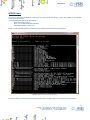
1
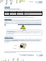
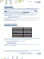
WEB-IO-BOX CONTROL UNIT USER MANUAL Rel. 01.00.0000 (Hardware code: Web-IO-Box) 1 www.ipses.com WEB-IO-BOX _____________________________ Information provided in this manual is property of IPSES S.r.l. and must be considered and treated as confidential. This publication can only be reproduced, transmitted, transcribed or translated into any human or computer language with the written consent of IPSES S.r.l. Information in this documentation has been carefully checked and is believed to be accurate as of the date of publication; however, no responsibility is assumed of inaccuracies. IPSES will not be liable for any consequential or incidental damages arising from reliance on the accuracy of this documentation. Information contained in this manual is subject to change without notice and does not represent a commitment on the part of IPSES. The design of this instrument is subject to continue development and improvement. Consequently, the equipment associated to this document may incorporate minor changes in detail from the information hereafter provided. All brand or product names are trademarks or registered trademarks of their respective holders. This manual in English is the original version. Printed in Italy Copyright 2013-2015 IPSES S.r.l. All rights reserved. 2 IPSES S.r.l. Via Trieste, 48 - 20020 Cesate (MI) - ITALY Tel. (+39) 02/99068453 Fax (+39) 02/700403170 http://www.ipses.com e-mail [email protected] WEB-IO-BOX GUARANTEE IPSES warrants to the end-user in accordance with the following provisions that its branded hardware products, purchased by the end-user from IPSES company or an authorized IPSES distributor will be free from defects in materials, workmanship and design affecting normal use, for a period of one year as of the original purchase date. Products for which proper claims are made will, at IPSES’s option, be repaired or replaced at IPSES’s expense1. Exclusions This Guarantee does not apply to defects resulting from: improper or inadequate installation, use or maintenance; actions or modifications by unauthorized third parties or the end-user; accidental or wilful damage or normal wear and tear. Making a claim Claims must be made by contacting IPSES office within the guarantee period. Please, contact: IPSES S.r.l. - Via Suor Lazzarotto, 10 - 20020 Cesate (MI) Italy Tel. (+39) 02 39449519 – (+39) 02 320629547 Fax (+39) 02 700403170 http://www.ipses.com - e-mail: [email protected] Limitation and Statutory Rights IPSES makes no other warranty, guarantee or like statement other than as explicitly stated above and this Guarantee is given in place of all other guarantees whatsoever, to the fullest extent permitted by law. In the absence of applicable legislation, this Guarantee will be the end-user’s sole and exclusive remedy against IPSES. General Provisions IPSES makes no express warranties or conditions beyond those stated in this warranty statement. IPSES disclaims all other warranties and conditions, express or implied, including without limitation implied warranties and conditions of merchantability and fitness for a particular purpose. IPSES’s responsibility for malfunctions and defects in hardware is limited to repair and replacement as set forth in this warranty statement. IPSES does not accept liability beyond the remedies set forth in this warranty statement or liability for incidental or consequential damages, including without limitation any liability for products not being available for use or for lost data or software. 1 With the exclusion of shipping costs for and from IPSES’s development office. 3 IPSES S.r.l. Via Trieste, 48 - 20020 Cesate (MI) - ITALY Tel. (+39) 02/99068453 Fax (+39) 02/700403170 http://www.ipses.com e-mail [email protected] WEB-IO-BOX WARNING! ELECTRICAL DEVICES COULD DAMAGE EQUIPMENT OR PROPERTY OR CAUSE PERSONAL INJURY This guide contains instructions and technical features of the WEB-ADIO Control Unit. Read with attention before attempting to install. It is the responsibility of the technician to undertake all the safety rules provided by the law during the installation and the use of this device. For any information which is not contained in this guide, please contact: IPSES S.r.l. - Via Suor Lazzarotto, 10 - 20020 Cesate (MI) Italy Tel. (+39) 02 39449519 – (+39) 02 320629547 Fax (+39) 02 700403170 http://www.ipses.com - e-mail: [email protected] 4 IPSES S.r.l. Via Trieste, 48 - 20020 Cesate (MI) - ITALY Tel. (+39) 02/99068453 Fax (+39) 02/700403170 http://www.ipses.com e-mail [email protected] WEB-IO-BOX TABLE OF CONTENTS GENERAL FEATURES ..............................................................................................7 REMOTE CONTROL SERVICE .................................................................................... 16 http SERVER ...................................................................................................... 17 SERVER telnet .................................................................................................... 31 SNMP SERVER ................................................................................................... 35 PROBLEMS RESOLUTION: ....................................................................................... 37 DEMO SOFTWARE ............................................................................................... 38 PRODUCT CODE ................................................................................................. 47 IPSES I/O CARD AVAILABLE MODELS ........................................................................... 48 CONTACTS ....................................................................................................... 52 ENGINEERING PROBLEM REPORT .............................................................................. 54 5 IPSES S.r.l. Via Trieste, 48 - 20020 Cesate (MI) - ITALY Tel. (+39) 02/99068453 Fax (+39) 02/700403170 http://www.ipses.com e-mail [email protected] WEB-IO-BOX REVISION HISTORY Manual revision history Revision/ Date 01.00.0000 April 2013 Description Author First version Released Mancuso C. 6 IPSES S.r.l. Via Trieste, 48 - 20020 Cesate (MI) - ITALY Tel. (+39) 02/99068453 Fax (+39) 02/700403170 http://www.ipses.com e-mail [email protected] WEB-IO-BOX GENERAL FEATURES WEB-IO BOX is a control unit integrated on a box. The size is 160 x 95 x 65 mm ( 6,30 x 3,74 x 2,56 inches) and the box is suitable for DIN fixing rail. The system needs an external power supply to operate. From +5V up +32V. WEB-IO BOX can check sixteen optocoupled inputs and drive sixteen optocoupled outputs. Both are reciprocally isolated in two groups of eight. The control and the configuration of the device are achieved through Ethernet interface thanks to an http browser or a MIB browser, or a telnet client, or using the demo software provided with. User can set the status of each output at the power-up: this status will be saved in a non-volatile memory. The card allows to perform a firmware upgrade using directly the server implemented on it, so there is not the necessity to use an external hardware or software component. La scheda permette di eseguire un upgrade del proprio firmware direttamente da pagina web, senza l’utilizzo di hardware o software dedicato. 7 IPSES S.r.l. Via Trieste, 48 - 20020 Cesate (MI) - ITALY Tel. (+39) 02/99068453 Fax (+39) 02/700403170 http://www.ipses.com e-mail [email protected] WEB-IO-BOX CARD DESCRIPTION WEB-IO card (contained inside the box) is shown in the picture 1 below: in the upper part of the card the sixteen outputs are divided in two groups of eight (numbered from 0 up to 7 on the card serigraphy), and, similarly, in the lower part of the card there are the sixteen inputs (numbered and divided in the same way). In picture n. 2 and n. 3 the relevant parts are highlighted as they appears on the box. POWER SUPPLY LED D2 LED D3 LED D4 OUT15 ÷ OUT8 OUT7 ÷ OUT0 Configuration switches ETHERNET Port IN0 ÷ IN7 IN8 ÷ IN15 Picture 1: WEB-IO BOX card ETHERNET Port IN0 ÷ IN7 IN8 ÷ IN15 Picture 2: WEB-IO BOX side with inputs and Ethernet port 8 IPSES S.r.l. Via Trieste, 48 - 20020 Cesate (MI) - ITALY Tel. (+39) 02/99068453 Fax (+39) 02/700403170 http://www.ipses.com e-mail [email protected] WEB-IO-BOX LED D2 LED D3 LED D4 OUT7 ÷ OUT0 OUT15 ÷ OUT8 Configuration switches POWER SUPPLY Picture 3: WEB-IO BOX side with outputs and configuration switches LED Description: D2 D3 D4 Green LED: Status LED (see relevant paragraph) Green LED: Status LED (see relevant paragraph) Red LED: Status LED (see relevant paragraph) Description of configuration switches: SW1 SW2 SW3 SW4 Reset hardware con ripristino dei parametri di fabbrica Software configuration of addresses (see relevant paragraph “ADDRES CONFIGURATION”) Reserved Reserved 9 IPSES S.r.l. Via Trieste, 48 - 20020 Cesate (MI) - ITALY Tel. (+39) 02/99068453 Fax (+39) 02/700403170 http://www.ipses.com e-mail [email protected] WEB-IO-BOX OUTPUTS The sixteen outputs are completely opto-isolated, both among them in two groups of eight and towards all signals on the device. Here below there are the diagrams of two typical connections of external device to WEB-IO BOX: in the first case (Picture 4a), the card will manage directly some loads (with maximal current of 150mA for each output). In the second case (Picture 4b), the card is connected to a high impedance device (i. e. the inputs of a PLC). Picture 4a: diagram of the output connections: directly managing of loads Picture 4b: diagram of the output connections: connection to a high impedance device 10 IPSES S.r.l. Via Trieste, 48 - 20020 Cesate (MI) - ITALY Tel. (+39) 02/99068453 Fax (+39) 02/700403170 http://www.ipses.com e-mail [email protected] WEB-IO-BOX INPUTS The sixteen inputs are completely opto-isolated, both among them in two groups of eight and toward all signals on the device. We suggest to connect inputs following one of the two diagrams displayed below: -Picture 5a: use this way in case inputs have to detect the pressure from a switch or an open collector output. -Picture 5b: use this way in case inputs are directly controlled by a voltage. Picture 5a: diagram of input implementation: detection of the pressure from a switch or an open collector output Picture 6b: diagram of input implementation: inputs directly controlled by a voltage 11 IPSES S.r.l. Via Trieste, 48 - 20020 Cesate (MI) - ITALY Tel. (+39) 02/99068453 Fax (+39) 02/700403170 http://www.ipses.com e-mail [email protected] WEB-IO-BOX EXAMPLE OF USAGE The follow example shows how you can connect WEB-IO BOX for managing an external load with line supply by using relays. Picrure 6 shows how to connect WEB-IO card with an external supply load. Picture 6: external load with line supply management OPERATION MODES The firmware of the board implements two different modes, as specified in the following table. Mode Operative Bootloader Description This is the normal mode. During this status, the control of the outputs and PLC and Timeout functions are fully available. The interaction with the board can made by web browser, MIB browser, telnet, or demo software. Using this mode, the board waits for a firmware upgrade or a return to Operative mode. In this status all the outputs and PLC and Timeout function are disabled. The interaction with the board can only made by a web browser. 12 IPSES S.r.l. Via Trieste, 48 - 20020 Cesate (MI) - ITALY Tel. (+39) 02/99068453 Fax (+39) 02/700403170 http://www.ipses.com e-mail [email protected] WEB-IO-BOX STATUS LED D2, D3 and D4 LEDs indicate the status of the system. In Operative mode the LED configuration is the following one: LED D2 On Blinking LED D3 On Blinking LED D4 Blinking / On Blinking / Status Description Board correctly configured and operative Hardware resetting to factory settings or software TCP/IP address configuration telnet password modifying If D2 or D3 are Off, there is, respectively, an hardware or a firmware initialization error. In Bootloader mode D2, D3 and D4 LEDs light up repetitively in sequence, until one remains in this status. POWER SUPPLY The board is equipped with a power supply connector (see picture 1 at page 8 or Picture 3 at pag. 9: the connector is labeled as “POWER SUPPLY”) which allows to connect an external voltage supply to power the board: its value must be included from +5V up to +32V. The voltage supply can be used also as “Power Supply”, as indicated in Picture 4b and 5a: by these way, the galvanic isolation of the board between I/O and control logic will be lost, so the GNDs must be connected together to avoid irreversible damage of the card. WARNING! The maximum supply voltage must not exceed +32Vdc: in case of use of higher voltage the components of the board may damage irremediably. It is recommend to handle the board with care: the area around the switching regulator works at high temperature and it is possible to burn oneself. ETHERNET MODULE The physical layer of the Ethernet network protocol supports the 10Base-T standard and it is fully compliant with the 10/100/1000Base-T standard. WEB-IO BOX can be connected to any commercial router or switch without problems. The physical connection between the card and the network cable is made by the RJ45 connector, as shown in the following picture: Link LED Activity LED The green LED (Link LED) indicates the detection of the Ethernet network, the yellow LED (Activity LED) is on during the communication packets Tx/Rx activity. 13 IPSES S.r.l. Via Trieste, 48 - 20020 Cesate (MI) - ITALY Tel. (+39) 02/99068453 Fax (+39) 02/700403170 http://www.ipses.com e-mail [email protected] WEB-IO-BOX NETWORK SERVICES WEB-IO BOX hosts a server for http service, a server for telnet service, a server for SNMP (Simple Network Management Protocol) service and a client for SMTP (Simple Mail Transfer Protocol) service. Data transfer is based on a TCP/IP protocol: the protocol configuration parameters can be modified only from http service. To validate these changes a password named http service password is required. Similarly, to access telnet service an authentication password named telnet service password is required. Both passwords are case-sensitive alphanumerical strings with a valid length included between 1 and 8 characters. The default value for both is “ipses” and it can be modified only from the relevant service. The SNMP service supports both V1 and V2c versions. The last one implements a community-based service access,which is an authentication access method. It is possible to set up to 3 different communities both for read and write operations. The default communities are: - Write Community (“private”, “write”, “public”) - Read Community (“public”, “read”, “”). Each specified community can be 8 chars maximum length; if none community is specified, the access to the pertinent service (read and/or write) is blocked. The SMTP client allows to send e-mails alerts to different user-configurable recipients, based on status inputs change events. This service can be configured only by http pages. ADDRESSES CONFIGURATION The following table shows the default configuration parameter of each box: Parameter Hostname IP address Subnet mask Gateway address Primary DNS Secondary DNS http password telnet password Startup status outputs Security Level Value WEBIOBOARD 192.168.0.16 255.255.255.0 192.168.0.4 193.70.152.15 0.0.0.0 ipses ipses all OFF 0 The addresses for Primary DNS server and Secondary DNS server must be modified according to the addresses assigned from the network’s provider where you connect your box. For more information contact your network provider. It is possible to restore factory parameters following this procedure listed below: - disconnect power supply from the board - insert jumper J1 (see Picture 1) - connect power supply to the board If the procedure is successfully completed, D2 and D3 LEDs will flash alternatively for about 3 seconds. At this point it will be possible to remove jumper J1 form the board. If TCP/IP parameters of the network are not compatible with default board parameters, or if the IP address is already assigned to another device, you can reconfigure them choosing between the following two procedures: 14 IPSES S.r.l. Via Trieste, 48 - 20020 Cesate (MI) - ITALY Tel. (+39) 02/99068453 Fax (+39) 02/700403170 http://www.ipses.com e-mail [email protected] WEB-IO-BOX Manual configuration procedure - connect the box locally and directly to a PC equipped with a network card (without connect it to any network). - verify that in the Property items under Local Network Connection Status (LAN) window located in Control Panel » Network Connection Properties path the IP address of your PC is 192.168.0.1 and their Subnet Mask is 255.255.255.0. Otherwise set these values in their respective fields. - power on the board and access to http service typing in the URL browser the current board address (by default http://192.168.0.16/). - go to the TCP/IP Configuration page, then set the new parameters and save them. Verify Save & Reboot operation works successfully. - install the card in the network and access it with new parameters. Software configuration procedure - with the box already powered on, insert the jumper J1. - Run the address configurator software “WEB-IO Address Configurator.exe” included in the installer CD provided with the board, and follow the steps described in the paragraph “TCP/IP ADDRESS CONFIGURATION SOFTWARE”. - at the end of the configuration, remove jumper J1. IMPORTANT: do not disconnect the power supply during the address configuration procedure: a supply reset restore factory parameters. 15 IPSES S.r.l. Via Trieste, 48 - 20020 Cesate (MI) - ITALY Tel. (+39) 02/99068453 Fax (+39) 02/700403170 http://www.ipses.com e-mail [email protected] WEB-IO-BOX REMOTE CONTROL SERVICE The Remote Control service, based on P2P paradigm, allows the bidirectional communication and the reciprocal control between two WEB-IO family cards, wherever they are. The transportation protocol is UDP. This service is especially useful if you need to acquire and process signals in locations distant from each other. The previous picture shows the communication flux: when the service is active on both cards, the inputs status of the Board A will be replied on the outputs of the Board B, and in the same way, the inputs status of the Board B will be replied on the outputs of the Board A. On each card is not possible to manually set the outputs status until the service is active. The service parameter configuration is described in the following http Server paragraph. 16 IPSES S.r.l. Via Trieste, 48 - 20020 Cesate (MI) - ITALY Tel. (+39) 02/99068453 Fax (+39) 02/700403170 http://www.ipses.com e-mail [email protected] WEB-IO-BOX http SERVER The http server implemented on the board allows to manage up to 3 simultaneous sessions. To access the server, open a web browser and type the board IP address http://192.168.0.16/ in the URL field: you will be redirect to the main page, index.htm, as shown in Picture 6. The implemented server was tested and was resulted fully compliant with the following browser: - Microsoft Internet Explorer 9.0.8112.16421 - Mozilla Firefox 4.0.1 - Google Chrome 11.0.696.77 - Apple Safari 5.0.5 (7533.21.1) All the web pages fulfill the W3C standard. To avoid undesired accesses to control function of the board we have developed a multilevel security function: its description is demanded later in this paragraph. Picture 8: http server index page. On the left side of the WEB-IO control panel there is the menu (surrounded in orange in Picture 8) which allows to access the pages implemented on the http server. Input status and Output Status fields, surrounded in violet, report respectively the current status of each inputs and outputs. Output command buttons, labeled from 0 to 15, drive the outputs: each button pressure set or reset the relative output. If the freezing function for http page commands is enabled, these buttons are disabled. The filling colors used in the http page are correspondent to the LEDs mounted on the card. 17 IPSES S.r.l. Via Trieste, 48 - 20020 Cesate (MI) - ITALY Tel. (+39) 02/99068453 Fax (+39) 02/700403170 http://www.ipses.com e-mail [email protected] WEB-IO-BOX Temperature field, surrounded in green, shows the measured temperature by the sensor; if the board is not equipped with the temperature sensor, a message is displayed. The Remote Control communication status LED, surrounded in yellow, shows the current status of the Remote Control service. If this service is disabled the LED is grey, else if the service is active and the communication with another WEB-IO family is established the LED is green, instead, if the communication fails, the LED is yellow. In both of the last two cases the Output command buttons are disabled. If the communication is lost the current page shows the following error message: “Connection to WEB-IO board was lost”. Picture 9: Startup configuration page. Startup Configuration page, shown above in Picture 9, allows to read board parameters (like Serial Number and Firmware Version), and to set the startup output status through the Startup Status Panel form. Saved Status section displays the actual startup configuration stored in memory: yellow LEDs indicate outputs of which configuration is already saved. Clicking on LEDs of Set Status section it is possible to set the new startup configuration which will be stored only after the pressure of Save Startup Settings button. If the freezing function for http page commands is enabled, the button is disabled. 18 IPSES S.r.l. Via Trieste, 48 - 20020 Cesate (MI) - ITALY Tel. (+39) 02/99068453 Fax (+39) 02/700403170 http://www.ipses.com e-mail [email protected] WEB-IO-BOX Picture 10: Timeout parameters configuration page. Timeout Configuration page, shown in Picture 10, allows to read and to set the parameters of the Timeout function. Saved Status section display the status of the outputs if the Timeout field time elapses with no commands or requests received by the board. Clicking on LEDs of Set Status section it is possible to set new outputs configuration, while Timeout field allows to select the new timeout time among the following items: “No timeout”, “5sec”, ”10sec”, ”30sec”, ”1min”, ”5min”, ”10min”, ”30min”, ”1hour”. “No timeout” item disables the Timeout function on the board. The Save Timeout Setting button stores the new settings on the memory of the board. If the freezing function for http page commands is enabled, the button is disabled. The Timeout function has priority over PLC function, described next. When the Timeout function occurs, the outputs will be sets as configured and remain in this status, while any active PLC logic will be temporarily disabled, until the board will not receive a new command or request. 19 IPSES S.r.l. Via Trieste, 48 - 20020 Cesate (MI) - ITALY Tel. (+39) 02/99068453 Fax (+39) 02/700403170 http://www.ipses.com e-mail [email protected] WEB-IO-BOX Picture 11: Programmable Logic Configuration (PLC) page. PLC Configuration page, shown in Picture 11, allows to manage each output in function of the customizable status of the inputs (from 0 to 15). For example, as shown in picture above, user can set the output n. 3 to switch on when inputs 1-2-3-5-9-13-14 are high and inputs 6-15 are low (other inputs are don’t care). To do this, select the desired output through the Select Output ring in the upper part of the PLC configuration panel. In the Saved Status section will be shown the filter and mask values actually stored for the selected output. Clicking on LEDs and checkboxes of the Set Status section is possible to set the new inputs filter and mask values, respectively. If an input is not masked, it will be not considered from the logic function, independently of its filter status selection. To make the new values operative, click on Save PLC Setting. When the PLC function is enabled on an output, the output status will be set according the customizable input status. For this reason, it will be not possible to manually set that output until the PLC function is enable. To do this, user needs to disable the PLC function. To disable the PLC function on an output, all inputs must be not masked: the relative item in the Set output ring will became grey, otherwise it will remain blue. The Disable All PLC Mask button in the lower part of the PLC panel allows to reset and store the mask of each output, without modifying the filter settings. If the freezing function for http page commands is enabled, both the buttons are disabled. The Timeout function (previously described and shown in Picture 10) has priority over PLC function: if timeout occurs, all PLC enabled functions are temporarily disabled until the board will receive a new command or request. 20 IPSES S.r.l. Via Trieste, 48 - 20020 Cesate (MI) - ITALY Tel. (+39) 02/99068453 Fax (+39) 02/700403170 http://www.ipses.com e-mail [email protected] WEB-IO-BOX Picture 12: SNMP Community configuration page. The SNMP Community Configuration page, shown in Picture 12, allows to set the read and write communities for the SNMP server V2c. Each community can be a case-sensitive alphanumeric string, with a maximum length of 8 characters. If you do not want to set one or more communities, leave the extra fields blank. If all fields are left blank, it will be impossible to access to SNMP server. The queries run in the MIB browser can be evaluated from the SNMP server only if the community with which the request is generated is included in the configuration list. The button Save Community Configuration stores the settings on the board. If the freezing function for http page commands is enabled, the button ´save community configuration” is disabled. 21 IPSES S.r.l. Via Trieste, 48 - 20020 Cesate (MI) - ITALY Tel. (+39) 02/99068453 Fax (+39) 02/700403170 http://www.ipses.com e-mail [email protected] WEB-IO-BOX Picture 13: I/O label configuration page. I/O Label Configuration Panel page, shown in Picture 13, allows the association of a label, difined by the user, to any input and output. The maxium lenght of the label is 10 digits. If the command freezing funciton from hhtp page is enabled, the “save configuration” button is disabled. The e-mail generated by the system, as described in the paragraph below, will include the detailed status of each I/O. The I/O will be identified by the relevant label as defined in this configuration page. The page fields will be displayed with the strings saved on the board. 22 IPSES S.r.l. Via Trieste, 48 - 20020 Cesate (MI) - ITALY Tel. (+39) 02/99068453 Fax (+39) 02/700403170 http://www.ipses.com e-mail [email protected] WEB-IO-BOX Picture 14: E-mail parameters configuration page (SMTP client). The E-mail Configuration Panel, shown in Picture 14, allows to set the parameters to enable and to process the automatic alert email sending, based on an input status change. The SMTP Server parameters section allows to configure the SMTP server parameters through which the mail is sent: - SMTP Server: mail server address (to use a mail server outbound your local network it is necessary to set a valid DNS address in TCP/IP Configuration page). - Port: is the access port of the server (typically port 25). - User Name: is the authentication username to access the mail server. - Password: is the authentication password to access the mail server. The e-mail client uses extended protocol. Note: not all the SMTP servers need an authentication access. For further information contact your network administrator or the SMTP server operator. The Enable Sending Mail field allows to enable or disable the mail sending when almost one input status change occurs. The Mail header parameters section allows to set up to 5 different recipient addresses and the “Object” field for the e-mail. Each recipient address, formatted as [email protected], can be maximum 26 characters length, while the Mail Subject field can be maximum 30 characters length. The Save Configuration button allows to store the fields and the option selected. If the freezing function for http page commands is enabled, the button ”save configuration” is disabled. 23 IPSES S.r.l. Via Trieste, 48 - 20020 Cesate (MI) - ITALY Tel. (+39) 02/99068453 Fax (+39) 02/700403170 http://www.ipses.com e-mail [email protected] WEB-IO-BOX Sending e-mail is an asynchronous process, subjected to the successfully connection established with the mail server. If you cannot receive the mail as expected, be sure the SMTP server and addresses parameters are correct. The Enable Sending Mail checkbox should be selected. The board does not point out an advise if the mail sending fails. The time necessary to generate and process each mail depends on the SMTP server communication. The minimum waiting time between two consecutive mail is 1 second. A new mail can be generated only when the process related to previous mail is ended. When a mail process is active, any input status change is ignored: this means that, during this phase, any input changes which may occur in subsequent time instants are neglected. The board will register only the first useful change occurred after the end of current mail elaboration process. The picture on the left shows an example of generated mail body. 24 IPSES S.r.l. Via Trieste, 48 - 20020 Cesate (MI) - ITALY Tel. (+39) 02/99068453 Fax (+39) 02/700403170 http://www.ipses.com e-mail [email protected] WEB-IO-BOX Picture 15: Remote Control service configuration page. The Remote Control Configuration page, shown in Picture 15, allows to set the configuration parameters for the Remote Control service. In the upper section of the page the current MAC and IP addresses of the board are displayed. To establish the communication between two (A and B) WEB-IO family boards user must configure the following parameters in both systems: - MAC Address of the destination board - IP Address of the destination board - UDP port for incoming packets (Local UDP Port) - UDP port for outcoming packets (Remote UDP Port) The Local Port of the board A must be set as the Remote Port of the board B, and vice versa. The user must ensure that the UDP ports selected are not reserved or used by another service. The Enable Remote Control Communication checkbox enables or disables the service. The Save Configuration button stores the fields and the option in memory. If the freezing function for http page commands is enabled, the button is disabled. In the lower section of the page is shown the status of the service, thanks to the Remote Control communication status LED. If the service is disabled the LED is grey. If the service is enabled but no incoming packets are detected the LED is yellow. If the packets are detected, the LED is green. The ping function is useful to test the reachability of the destination board. Till the Remote Control service is enabled, the PLC and the Timeout functions are disabled and the manual control of the outputs is forbidden. 25 IPSES S.r.l. Via Trieste, 48 - 20020 Cesate (MI) - ITALY Tel. (+39) 02/99068453 Fax (+39) 02/700403170 http://www.ipses.com e-mail [email protected] WEB-IO-BOX Picture 16: TCP/IP protocol and http password configuration page. TCP/IP Configuration page, shown in Picture 16, allows to modify some TCP/IP protocol parameters and the http password of the board. The hostname can be maximum 16 alphanumeric case-insensitive characters length. To modify and save these parameters, it is necessary to insert a valid http password then press the Save Configurations & Reboot button. If the password is invalid or data processing fails, configured parameters will not be saved and you will be redirect to an error page. To came back, click on the appropriate link. The Enable Change Password checkbox allows to insert a new http password in the New Password and Confirm New Password fields. The Load Factory Configuration button allows to restore factory parameters, excepted for the http password that will not be modified. At the end of the page is available the Ping function which allows to verify the connection between card and inserted address. If the communication is lost, the ping section shows the following error message: “Connection to WEB-IO board was lost”. Warning: if the saved parameters are invalid or they could not be resolved in your network, you will lose the communication. To restore all default parameters, follow the procedure described in “ADDRESSES CONFIGURATION” paragraph. 26 IPSES S.r.l. Via Trieste, 48 - 20020 Cesate (MI) - ITALY Tel. (+39) 02/99068453 Fax (+39) 02/700403170 http://www.ipses.com e-mail [email protected] WEB-IO-BOX Picture 17: Security settings configuration page. The Security Settings configuration page, shown in Picture 17, allows to set the security levels, only for functions implemented on the http server. Its purpose is to inhibit the control of the board from unauthorized accesses. There are 3 security levels: - Level 0: security option is not enabled; - Level 1: security on http pages; - Level 2: security on URL commands, and automatically on http pages. The security Level 0 allows to control the I/O status and functionality of the board from anyone who enters the http pages or who knows the URL commands described in this manual. To raise the security to Level 1 it is necessary to set the “Freeze http page commands” checkbox: the control buttons on the http pages will be disabled, but the URL commands will continue to be processed by the board, as described below in the “I/O MANAGEMENT THROUGH http” paragraph. To set Level 2 is enough enabling the “Freeze URL line commands” checkbox: the Freeze http page commands” checkbox will be automatically enabled and both buttons on http pages and URL commands will be blocked. However, the reading I/O URL commands will keep to be processed. Resetting board parameters will configure again the security Level to 0. The current security settings are shown during the page loading. To save new settings, it is mandatory insert the correct http password before clicking the Save Security Settings button. 27 IPSES S.r.l. Via Trieste, 48 - 20020 Cesate (MI) - ITALY Tel. (+39) 02/99068453 Fax (+39) 02/700403170 http://www.ipses.com e-mail [email protected] WEB-IO-BOX Picture 18: Bootloader mode access page. The Bootloader Setting page, shown in Picture 18, allows to run the bootloader mode on the board for a firmware upgrade. To enable this mode, it is mandatory to insert the correct http password before clicking on the Run Bootloader Mode button: so you will be redirect to the following network address: http://current-ip/bootloader (where current-IP is the current IP address of the board, i.e. 192.168.0.16). Picture 19 shows the only page reachable in Bootloader mode. Until the board remain in this status, the SNMP server and the telnet server are unreachable, while all the outputs and PLC and Timeout function are disabled. Warning: the board will remain in bootloader mode until the installation of a new firmware or the clicking on Exit button will be done. The board will not work until the restoration of the normal mode. If none of the two processes listed above will be executed (i.e. the page will be closed using the “x” button on the right upper corner of the window), it will be necessary opening the firmware upgrade page once again by the relevant IP address, proceeding with the installation of a valid firmware or exit the process in the proper way. 28 IPSES S.r.l. Via Trieste, 48 - 20020 Cesate (MI) - ITALY Tel. (+39) 02/99068453 Fax (+39) 02/700403170 http://www.ipses.com e-mail [email protected] WEB-IO-BOX Picture 19: Firmware upgrade page. The Browse button allows to select the .bin file with the new firmware, and the Upload button starts the installation process. If the upgrade is completed successfully, the board will automatically return to Operative mode and you will be redirect to index page. To exit the Bootloader mode with no upgrade, click the Exit button. Picture 20: Firmware version information page. The Board Info page, shown in Picture 20, lists the main information concerning firmware version and http page version running on the board. 29 IPSES S.r.l. Via Trieste, 48 - 20020 Cesate (MI) - ITALY Tel. (+39) 02/99068453 Fax (+39) 02/700403170 http://www.ipses.com e-mail [email protected] WEB-IO-BOX I/O MANAGEMENT THROUGH http WEB-IO BOX can be interfaced to embedded system where it may be useful to command or to read the I/O status through http protocol, without performing a parsing of the previous described web pages. The I/O reading can be performed by edit in the URL the following address: http://current-ip/file, where current-ip is the board address (i.e.: 192.168.0.16) and file is one among the following ones: - getdo.cgi getdi.cgi read the digital output status in hexadecimal format (MSB is Out15 and LSB is Out0). read the digital input status in hexadecimal format (MSB is In15 and LSB is In0). To set a digital output, edit in the URL the following address: http://current-ip/digbutton.cgi?dbtn=x, where x is referred to the digital output desired (0-15). This command acts on the selected output by performing a change of its current status: it does not allows to select the logical level (high or low), but only to perform a toggle, unless the output is not tied to a logical level by the PLC function enable. If the security option “Freeze URL line commands” is enabled, the command sent to the board will not process. The http page shown by the board as response to these commands is a blank page: the user must take care to digit correctly the URL addresses and the parameters. 30 IPSES S.r.l. Via Trieste, 48 - 20020 Cesate (MI) - ITALY Tel. (+39) 02/99068453 Fax (+39) 02/700403170 http://www.ipses.com e-mail [email protected] WEB-IO-BOX SERVER telnet To connect to telnet server implemented on the board it is enough a telnet client program (i.e. the client installed in your operative system or the hyperterminal). The configuration parameters of the client must be: - telnet communication port: 23; - echo: on (if you want to see typed characters); - termination characters: <CR LF> (\r\n). Picture 21 shows the initial snapshot: to access the server, insert the telnet password, then press “Enter”. Picture 21: telnet server access page and help request. This service allows to read I/O status, to read card parameters and to manage outputs. All commands are case-insensitive.. 31 IPSES S.r.l. Via Trieste, 48 - 20020 Cesate (MI) - ITALY Tel. (+39) 02/99068453 Fax (+39) 02/700403170 http://www.ipses.com e-mail [email protected] WEB-IO-BOX Commands list is displayed below: Command Q SN FV BD SV HN MAC IP SUB GW DNS DNS2 Ix or DIx Ox or DOx Ax or ADx Sx or SDx AA –S[xxxxxxxxxxxxxxxx] or ADA – S[xxxxxxxxxxxxxxxx] T SP SP –S[xxxxxxxxxxxxxxxx] or SPD – S[xxxxxxxxxxxxxxxx] TM TM –T[x] TM –S[xxxxxxxxxxxxxxxx] PLCy PLCy –M[xxxxxxxxxxxxxxxx] PLCy –F[xxxxxxxxxxxxxxxx] EIC EICx FR FRx RM MS MP Description Closes telnet connection Requests board serial number Requests firmware version Requests firmware build date Requests TCP/IP stack version Requests board hostname Requests board MAC address Requests board IP address Requests board Subnet mask Requests board Gateway address Requests board Primary DNS server address Requests board Secondary DNS server address Requests input status (x = 0-15 / A all) Requests output status (x = 0-15 / A all) Actives related output (x = 0-15 / A all) Disables related output (x = 0-15 / A all) Sets the status of each output, from Out0 to Out15 Requests measured temperature Requests all startup outputs status Sets startup status (x = 0/1 – Off/On) of each output, from Out0 to Out15 Requests timeout settings (outputs status Out0..Out15 – timeout time [08]) Sets timeout time (x = 0-8) Sets timeout status (x = 0/1 – Off/On) of each output, from Out0 to Out15 Requests mask and filter settings (M0..M15 – F0..F15 related to In0..In15 inputs) for the y output (y = 0-15) Sets the mask status (x = 0/1 – Off/On) of each input, from In0 to In15, for the y output (y = 0-15) Sets the filter status (x = 0/1 – Off/On) of each input, from In0 to In15, for the y output (y = 0-15) Requests the operating status of the notification of change of inputs Enable/Disable the notification function of change of inputs (x= 0/1 – Off/On) Requests Fast Response status (0/1 = Off/On) Set Fast Response status (x=0/1 – Off/On) Request the Remote Control Service Requests the Enable Status of Log Memory Requests the logging memory parameters (memory size, current location, overwrite status) Answer type 1 1 1 1 1 1 1 1 1 1 1 2 2 3 3 3 1 2 3 1 3 3 1 3 3 4 3 4 3 2 The change of the password in telnet does not perform a reboot of the board or the automatic disconnection from the current session, on the contrary to what happens in the analogous http service. Obviously, next telnet access to board, here included the use of demo software, must be authorized by the new password. The typing of an excessive number of chars (over 29) saturates the receiving buffer of the card and consequently the session will be lost. 32 IPSES S.r.l. Via Trieste, 48 - 20020 Cesate (MI) - ITALY Tel. (+39) 02/99068453 Fax (+39) 02/700403170 http://www.ipses.com e-mail [email protected] WEB-IO-BOX The following table lists of answers related to the edited command: Answer type Description 2 3 4 The answer is preceded by a 18 chars length descriptive string. For example the SN command generates the following answer: “Serial number: 2010000”. The data answer is preceded by a descriptive string with variable length, related to the typed command. The answer to these I/O setting commands is: "\x1b[34mdone \x1b[0;1m". The answer is made by a single char: 0 = Off, 1 = On. 4 The answer is made by a single char: 0 = Off, 1 = On. 1 The next table encode the timeout time parameter used in TM and TM –T[x] commands: Parameter 0 1 2 3 4 5 6 7 8 Value No timeout 5 seconds 10 seconds 30 seconds 1 minute 5 minutes 10 minutes 30 minutes 1 hour DEVELOPMENT OF CONTROL APPLICATIONS WITH telnet PROTOCOL It is possible to develop a control application for the WEB-IO BOX based on telnet Server: the user program should be able to manage the strings generated from the server. The following are the strings used in the program, with a brief description of them. Server telnet access string. “\x1b[2J\x1b[31m\x1b[1mWEB-IO Telnet Server 1.2\x1b[0m\r\nTo access the service insert the password \r\nPassword: ” Answer string to incorrect password: the telnet socket will be closed. "\r\nAccess denied\r\n\r\n" Answer string to correct password: the command prompt will be shown. "\r\n\r\n\x1b[1;32mLogged in successfully\x1b[0m - Press 'q' to quit\r\n\r\n" Command prompt: it is shown after each command executed, except CP command. "\r\n> " Answer string to each invalid command or request "\x1b[33merror\x1b[0;1m" UTILITY DESCRIPTION Il comando EICx (Advise on Input Change) permette di abilitare o disabilitare la stampa dello stato degli ingressi, in formato esadecimale, ogni qualvolta si verifica la variazione di almeno un ingresso. Il comando è disabilitato di default ad ogni nuovo accesso al server telnet. The EICx (Advise on Input Change) command allows to enable or disable the printing of the status of all inputs, in hexadecimal format, every time there is a change of at almost one input. 33 IPSES S.r.l. Via Trieste, 48 - 20020 Cesate (MI) - ITALY Tel. (+39) 02/99068453 Fax (+39) 02/700403170 http://www.ipses.com e-mail [email protected] WEB-IO-BOX The command is disabled by default at every server access. The FRx (Fast Response) command allows to enable or disable the printing of the descriptive strings. This utility is useful to write codes in which the program focuses his resource only to process the data received in a synthetic form, without parsing all the strings. The command is disabled by default at every server access. The CP (Change Password) command is made by three phases: in the first one, it is requested to insert the new password: "\r\nEnter new password: " Next one it is requested to confirm the new password: "\r\nConfirm new password: " Now, if the password match is valid, the answer string will be: "\r\n\r\nPassword changed successfully!\r\n" Otherwise it will be: "\r\n\r\nPassword change fails!\r\n" The change of the password in telnet does not perform a reboot of the board or the automatic disconnection from the current session, on the contrary to what happens in the analogous http service. Obviously, next telnet access to board, here included the use of demo software, must be authorized by the new password. 34 IPSES S.r.l. Via Trieste, 48 - 20020 Cesate (MI) - ITALY Tel. (+39) 02/99068453 Fax (+39) 02/700403170 http://www.ipses.com e-mail [email protected] WEB-IO-BOX SNMP SERVER To connect the SNMP server implemented on the board user can use any MIB browser program, like iReasoning MIB Browser2. Once the communication with the board is on, it is necessary to be sure the browser is correctly configured according the following check list. - The MIB Tree must include the .mib file provided with the CD. To load it, use the command “File Load MIBs” and search through the folders, selecting the file WEB-IO.mib. - The Agent must be configured properly with communities parameters. To verify it, use the command “Tools Options” and select the tab Agents. The Add button allows to configure a new Agent, setting IP board address, Port (161), Version (2), Read and Write Communities. Picture 22: MIB browser display 2 Downloadable from www.ireasoning.com web site 35 IPSES S.r.l. Via Trieste, 48 - 20020 Cesate (MI) - ITALY Tel. (+39) 02/99068453 Fax (+39) 02/700403170 http://www.ipses.com e-mail [email protected] WEB-IO-BOX Picture 23: MIB browser and SNMP Agent configuration. Picture 23 shows the MIB browser and the configuration of the related SNMP Agent parameters. The MIB Tree has six branches, each of them has several leafs: - product, where to read information about the board - setup, where to set the parameters for two different traps - inputs, where to read input status - outputs, where to read or set the output status - status, where to read the PLC and Timeout function status (On/Off) and the measured temperature (if available) - events, which contains the variable associated to the Trap’s event, and it can be read or written. Using SNMP server it is not possible to configure the PLC and Timeout functions. The Operation selector specifies the request to be sent to the server. The answers to reading requests are shown in the Result Table; instead, to set a parameter, it is mandatory to insert the value, according to the specified kind, in the relevant form of the popup window. For further information about commands and functions, consult your browser helper. EVENTI DI TRAP The SNMP server implemented on WEB-IO BOX can generate two separate Trap events, both of them associated to a change of inputs status. Each event can be configured independently. The minimum gap between two trap events is 10 seconds. The Traps generated are compliant to v2c protocol specification and the information is stored in a sequence of two 16 bit format varbinds: the first one encodes the input status (In0 – In15), the second one encodes the output status (Out0 – Out15). The parameters to configure, for each event, are: - trapEnable: 0/1 respectively to disable/enable the event notification. - trapReceiverIPAdrress: IP address of the receiver machine (i.e. the IP address of your PC). - trapCommunity: a valid community name to receive the event notification. By default, the parameters of the Trap events are reset at every rebooting: to avoid this condition, set the save_option variable in the setup path before configuring the parameters values. If the save_option variable is deactivated at the startup, the parameters are reset. To see in your mib browser the list of the generated events, is necessary to open the Trap Receiver window with the “Tools Trap Receiver” command. 36 IPSES S.r.l. Via Trieste, 48 - 20020 Cesate (MI) - ITALY Tel. (+39) 02/99068453 Fax (+39) 02/700403170 http://www.ipses.com e-mail [email protected] WEB-IO-BOX PROBLEMS RESOLUTION: Below verification procedure steps to investigate board malfunctions are listed. If the problem is not resolved, contact the technical support of IPSES S.r.l. sending the Engineering Problem Report included in this manual or downloadable from IPSES website at the following address http://www.ipses.com/PDF/IPSES-engineering_problem_report.pdf - Verify the correct power supply and operation of the board (see status LEDs). Verify the correct connection of the network cable both on board and LAN side (network card, switch …) and verify if the board is visible from the network. Verify the compatibility of board addresses (IP, subnet, gateway) in the operative network. If there is no compatibility, ensure to configure them properly. Try to ping the IP address of the board. Make sure the IP address in the URL field is correct (http service). Verify there are no more than 3 simultaneous connection opened on the same board (http service). Make sure the password inserted in the TCP/IP Configuration page is correct (http service). Make sure the telnet communication port is number 23 (telnet service). Make sure the telnet access password is correct: it is case sensitive (telnet service). Verify there is no telnet communication already active on the board, via telnet client or demo software (telnet service). Verify the DNS server addresses. Verify the address entered with the ping function (http service). Check the MIB browser is set properly through the .mib correct file loading and communities settings (SNMP service). 37 IPSES S.r.l. Via Trieste, 48 - 20020 Cesate (MI) - ITALY Tel. (+39) 02/99068453 Fax (+39) 02/700403170 http://www.ipses.com e-mail [email protected] WEB-IO-BOX DEMO SOFTWARE A CD with a demo software is provided with the card. This demo software for Windows O.S., based on telnet service, allows to manage the main functions of WEB-IO BOX. To use this software, it is necessary a telnet communication is not already opened on the card, while a http communication service can exist simultaneously with. This software allows to manage up to 100 WEB-IO devices simultaneously connected to an Ethernet network. At the software start-up, the program shows a windows (Picture 24) where it is possible to initialize the connection of the devices managed through the software. To open the connection with a card, insert its IP address and its telnet Password in the relevant fields, then click on the Connect button. After few seconds, if the connection is successfully opened, the IP address, password and serial number parameters of the board will be shown on Connected devices table; otherwise an error message will be shown in the Operation message indicator. The Start Program button will be enabled only when the connected device list will contain almost one connected device. It is no possible to add other devices once the initialization phase is terminated: to do this, close the program and restart it repeating the initialization steps. The Quit Program button allows to close the software without opening the main window. Picture 24: Initialization connection panel of the demo software. Picture 25a shows a snapshot of the main window of the software. To enable the control of one of the initialized cards it necessary to select its Serial Number from the Device S/N ring menu. The selection of a new board allows to automatically update the inputs and outputs status and to update Firmware Version and IP Address fields. The temperature indicator is updated only if the card is equipped with the relevant sensor; otherwise the indicator will be disabled. 38 IPSES S.r.l. Via Trieste, 48 - 20020 Cesate (MI) - ITALY Tel. (+39) 02/99068453 Fax (+39) 02/700403170 http://www.ipses.com e-mail [email protected] WEB-IO-BOX Picture 25a: Main windows of the demo software. The field Last Command Sent (surrounded in orange in Picture 25a) shows the last executed operation. The selectors in the upper part directly manage the sixteen outputs in real time, while the Read Output button update the software output status virtual LEDs. Both logic inputs and outputs status can be achieved in two ways, thanks to the selectors ring menu (surrounded in blue in Picture 25a): the manual mode performs an asynchronous acquisition when you push respectively the Read Input button or Read Output button, while the automatic mode performs a continuous polling of the inputs and/or outputs status. The polling rate is customizable by the Polling Time controls (showed in Picture 25b): these fields accept values between 1.5s and 10s, with a step of 0.5s. In both cases, the software LEDs are updated at each acquisition: the one referred to the inputs status are green, while the ones referred to the outputs status are red. Picture 25b: Automatic acquisition mode of the inputs and the outputs. 39 IPSES S.r.l. Via Trieste, 48 - 20020 Cesate (MI) - ITALY Tel. (+39) 02/99068453 Fax (+39) 02/700403170 http://www.ipses.com e-mail [email protected] WEB-IO-BOX The objects in the purple section (see Picture 25a) allow to configure masks and filters for PLC functions. Clicking on the relevant square LED of an output a pop-up window will appear, as shown in Picture 26. For each output the square LED is on only when almost an input is masked, so the PLC function is enabled, otherwise it is off and the PLC function is disabled. The Disable all PLC button resets and stores all masks for each output, without modifying any filter. Picture 26: mask and filter PLC configuration pop-up window. When the pop-up window is opening, the mask and filter configuration currently stored for the selected output is shown. If an input mask is enabled, it is possible to modify its filter status too, otherwise the last one is dimmed. To modify a filter status, click on the relevant square LED. If all inputs are not masked, the enable/disabled square LED, surrounded in blue in Picture 26, is off and the “DISABLED” message appears. The Set PLC button allows to store the configuration settings, while the Cancel button closes the pop-up window without saving them. The square LED surrounded in red in Picture 25a shows the status of the Timeout function. If it is disabled, the LED is off and the TIMEOUT DISABLED message appears. Three buttons on the right (surrounded in green in Picture 25a) allow to open three windows: the first one for the outputs (Advanced Output), the second one for the inputs (Advanced Input) and the last one for the read and write commands in the non-volatile memory (Advanced Commands). The Advanced Output window (see Picture 27) allows the typical operations you can perform on the outputs of the device. 40 IPSES S.r.l. Via Trieste, 48 - 20020 Cesate (MI) - ITALY Tel. (+39) 02/99068453 Fax (+39) 02/700403170 http://www.ipses.com e-mail [email protected] WEB-IO-BOX Picture 27: Advanced Output window. The output commands are listed below: Activation of each output for both ports Reset of the outputs (all outputs are switched off) Reading of the status of each output for each port Command and reading of a single output Reading of the start-up configuration Setting of the start-up configuration Reading of the Timeout function configuration (outputs status and timeout time) Settings of the Timeout function configuration (outputs status and timeout time) 41 IPSES S.r.l. Via Trieste, 48 - 20020 Cesate (MI) - ITALY Tel. (+39) 02/99068453 Fax (+39) 02/700403170 http://www.ipses.com e-mail [email protected] WEB-IO-BOX Advanced Input window (see Picture 28) allows the typical operations you can performed on the inputs of the device. The input commands are listed below: Reading of the status of each input for each port Reading of the status of a single input Picture 28: Advanced Input window. The Advanced Commands window (see Picture 29) displays all TCP/IP and firmware configuration parameters of the current board and allows to change the telnet password. The new telnet password must be inserted in the New Password field and replied in Confirm New Password field: it could be any alphanumeric strings with a valid length between one and eight characters. The Enable Change Password checkbox enables the Set New Password button. The result of the modifying command will be shown in the Last Command Sent field in the lower part of the main panel, while if an error is generated by the password validity check operation, the error message will be popped up. Picture 29: Advanced Command window. 42 IPSES S.r.l. Via Trieste, 48 - 20020 Cesate (MI) - ITALY Tel. (+39) 02/99068453 Fax (+39) 02/700403170 http://www.ipses.com e-mail [email protected] WEB-IO-BOX TCP/IP ADDRESS CONFIGURATOR SOFTWARE WEB-IO Board Address Configurator, provided with the card, is a software which allows to configure remotely TCP/IP addresses for WEB family IO control units (WEB-IO, WEB-IOBOX, WEB-ADIO, WEB-IOWiFi, WEB-ADIO-WiFi). Only for WiFi models it is also possible to configure the wireless board parameters. The configuration of the device is achieved through Ethernet interface, or, only for WiFi models, also with the wireless interface. In the last case it is necessary that the card can connects itself to the Access Point, i.e. the SSID and authentication parameters must be correct. To work properly, only one card per time must be set in address configuration mode, even if you have more than one board of the WEB family connected. WEB-IO Board Address Configurator software is able to communicate with every IP address, excluded the reserved broadcast address (255.255.255.255). That means it is possible to configure also cards with out-of-net IP addresses. ADDRESS CONFIGURATION MODE To enable the hardware address configuration mode, follow the procedure listed below (for the position of configuration switches see Picture 30) OUT7 ÷ OUT0 OUT15 ÷ OUT8 Configuration switches Picture 30: WEB-IO BOX side - position of configuration switches - With WEB-IO BOX powered on, mouve the sw2 switch in ON position (toward the box enclosure). - perform the desired software configuration. - At the end of configuration proceture, put again the sw2 switch in OFF position (outwards). Do not disconnect the power supply during the address configuration procedure. A reset of power supply performed with the sw1 switch in O position, will restore the factory parameters. 43 IPSES S.r.l. Via Trieste, 48 - 20020 Cesate (MI) - ITALY Tel. (+39) 02/99068453 Fax (+39) 02/700403170 http://www.ipses.com e-mail [email protected] WEB-IO-BOX ADDRESS CONFIGURATOR CONTROL PANEL The WEB-IO Board Address Configurator control panel, shown in Picture 31, allows to configure both TCP/IP parameters, like IP address, Subnet mask address, Gateway address and Primary and Secondary DNS server addresses, and wireless parameters to connect to the Access Point. The modification of these last ones can be enabled by the user, after a WiFi model card was previously selected. Before to set the new parameters, the user should properly select the target card through the Select Target Board ring: the wireless parameters will be enabled or disabled, based on selected model. Every field is saved on the board: it is important to compile each field with correct values. The Reboot enable checkbox allows to perform a software rebooting of the card after the address configuration is successfully ended. If the configuration process ends successfully, the status LEDs D2 and D3 on the board will flash for about one second. Picture 31: WEB-IO Address Configurator software control panel 44 IPSES S.r.l. Via Trieste, 48 - 20020 Cesate (MI) - ITALY Tel. (+39) 02/99068453 Fax (+39) 02/700403170 http://www.ipses.com e-mail [email protected] WEB-IO-BOX To send the new TCP/IP address configuration, click the Start button; during the communication with the card the Configuration LED is on. To exit the software, click on Quit button. If the communication handshake to the card is successful, the Serial number and Remote IP address fields in the Board Section are filled respectively with the current S/N and IP address of the card, as shown in Picture 32. The Board status field shows a message about the progress of the configuration status. Picture 32: Configuration successfully completed. If a communication error occurs, the Serial number field is empty and the Remote IP address field shows an invalid IP address (0.0.0.0), while an error message is shown in the Status section and the Start and Quit buttons are disabled until the error is reset, as shown in Picture 33. 45 IPSES S.r.l. Via Trieste, 48 - 20020 Cesate (MI) - ITALY Tel. (+39) 02/99068453 Fax (+39) 02/700403170 http://www.ipses.com e-mail [email protected] WEB-IO-BOX Picture 33: Error during configuration. Per configurare un’altra scheda, settarla in modalità address configuration come precedentemente descritto. Digitare quindi i nuovi parametri di indirizzo e cliccare il pulsante Start. Note: if you are using Windows Vista or Windows 7 on your PC, your operative system could ask you to unlock a firewall restriction when you click on the Start button. Confirm the unlocking of the firewall restriction, otherwise the communication of the software via Ethernet will be interdicted from the operative system. 46 IPSES S.r.l. Via Trieste, 48 - 20020 Cesate (MI) - ITALY Tel. (+39) 02/99068453 Fax (+39) 02/700403170 http://www.ipses.com e-mail [email protected] WEB-IO-BOX PRODUCT CODE Code WEB-IO-BOX WEB-IO-BOX T ETH-CABLE Description WEB-IO control card in a box suitable for DIN rail fixing. Power supply from +5V e +32V. WEB-IO control card in a box suitable for DIN rail fixing. Power supply from +5V e +32V. System equipped with temperature sensor Ethernet cable to connect the system TECHNICAL FEATURES Power supply: external, from 5V up to 32V (continuous current) Maximum current consumption: 240mA @5V, 250mA @12V Working temperature: from 0°C up to +60°C Storage temperature: from -40°C up to +85°C Interface toward PC: RJ45 Ethernet connector System dimensions: 160 x 100 x 20 mm (6.30 x 3.94 x 0.79 inches) Inputs: sixteen optocoupled inputs, reciprocally isolated in two groups of eight Maximum applicable voltage: Input Impedance: Logical LOW level: Logical HIGH level: 36V ≈ 2.5Kohm < 1V > 2.5V Outputs: sixteen optocoupled outputs, reciprocally isolated in two groups of eight, in an open-collector configuration Maximum output voltage: 36V Maximum output current: 150mA Protection: optocouplers with 2.500VRMS maximum operative isolation voltage Temperature sensor: Resolution: Accuracy: 0.0625°C ±1°C (max.) da +25°C a +65°C ±2°C (max.) da -40°C a +25°C e da +65°C a +85°C ±3°C (max.) da -55°C a -40°C e da +85°C a +125°C Supported protocols: Telnet: the card can work as a telnet server HTTP: the card can work as a web server SNMP: the card can work as an SNMP server SMTP: the card can work as an SMTP client 47 IPSES S.r.l. Via Trieste, 48 - 20020 Cesate (MI) - ITALY Tel. (+39) 02/99068453 Fax (+39) 02/700403170 http://www.ipses.com e-mail [email protected] WEB-IO-BOX IPSES I/O CARD AVAILABLE MODELS IO-69: Input/output Card with 6 inputs and 9 relay outputs and USB interface IO-69-USB is a self-powered card to manage six optocoupled inputs and nine relay outputs with USB interface. A timeout control allows to protect the connecting devices, turning off all the outputs if it does not receive commands from the host within a time configurable through software. Furthermore, there is the possibility to program all the outputs so that each one will activate only when inputs reach assigned conditions: in this case, IO- 69 acts like a programmable logic controller (PLC). The card is produced in two versions: with single pole double throw relay (SPDT) and with single pole single throw relay (SPST). IO-1616: Input/output Card with 16 inputs and 16 outputs and USB or RS232 interface IO1616 is a self-powered card to manage sixteen optoisolated inputs and sixteen optoisolated outputs with USB interface. The model is available also with RS232 interface, in this case the card needs external power supply. IO1616 can be directly connected to PLC, to input devices from operator and to other I/O systems. the status of each input On request, an integrated temperature sensor allows to know in real time the temperature of the system IO1616 is placed in. CAN-I/O: Input/output Card with 16 inputs and 16 outputs with CAN, USB and RS232 interface CAN-IO is a control unit equipped with CAN, USB and RS232 interfaces to manage sixteen optocoupled inputs and outputs. The card can work as standalone device on CAN BUS. Its configuration is achieved either through USB (in this case the board is selfpowered) or through RS232 interface. Easy to use and to configure, thanks to the provided software, CAN-IO is the right answer to the need to acquire and to drive digital signals through already existing CAN bus. CAN-IO can be directly connected to PLC, to input devices by operator and to other I/O systems. Each input and output status can be read by a field bus at any moment. Besides, thanks to LEDs fixed on, the status is shown directly on the board. An integrated temperature sensor allows to know in real time the temperature of the system CAN-IO is placed in. 48 IPSES S.r.l. Via Trieste, 48 - 20020 Cesate (MI) - ITALY Tel. (+39) 02/99068453 Fax (+39) 02/700403170 http://www.ipses.com e-mail [email protected] WEB-IO-BOX WEB-IO: Input/output Card with 16 inputs and 16 outputs, Ethernet interface, integrated web, telnet and SNMP servers and SMTP client. WEB-IO is a card to manage sixteen optocoupled inputs and sixteen optocoupled outputs with Ethernet interface, equipped with a web, a telnet and an SNMP servers, and an SMTP client. The web server allows to connect and to manage the card using any web browser (i. e. Internet Explorer or Firefox), with no needs to install a software on your PC. Besides, the card can be connected directly to a switch or to a router with no need to use a PC. It is also possible to develop a customized software managed by telnet service or SNMP client. The SMTP client allows to send alert email based on inputs status change events. WEB-IO can be directly connected to PLC, to input devices from operator and to other I/O systems. Each input and output status can be read by a web browser or a telnet client at any moment, besides it is shown directly on the board thanks to LEDs fixed on. On request, the card can be equipped with an integrated temperature sensor which allows to monitor in real time the temperature around the regulator voltage module. Through expansion connectors the card can be interfaced to a RTCLOG (Real Time Clock and Logger) optional module: by this way, it can perform a log of the I/O states on a dedicated memory. WEB-IO is available also in box version, it is provided with a demo software for Windows environment, based on telnet service. WEB-IO-WiFi: Input/output Card with 16 inputs and 16 outputs, Ethernet and WiFi interfaces, integrated web, telnet and SNMP servers WEB-IO-WiFi is a card to manage sixteen optocoupled inputs and sixteen optocoupled outputs with Ethernet and WiFi interfaces, equipped with a web, a telnet and an SNMP servers. The web server allows to connect and to manage the card using any web browser (i. e. Internet Explorer or Firefox), with no needs to install a software on your PC. Besides, the card can be connected directly to a switch or to a router, by this way it can be accessed by any PC connected to Internet. It is also possible to develop a customized software managed by telnet service or SNMP protocol. The board is available with built-in antenna or with ultra-miniature coaxial (U.FL) connector for external antenna connection. WEB-IO-WiFi can be directly connected to PLC, to input devices from operator and to other I/O systems. Each input and output status can be read by a web browser or a telnet client at any moment, besides it is shown directly on the board thanks to LEDs fixed on. On request, the card can be equipped with an integrated temperature sensor which allows to monitor in real time the temperature around the regulator voltage module. 49 IPSES S.r.l. Via Trieste, 48 - 20020 Cesate (MI) - ITALY Tel. (+39) 02/99068453 Fax (+39) 02/700403170 http://www.ipses.com e-mail [email protected] WEB-IO-BOX WEB-ADIO: Input/output Card with 8 analogical inputs, 8 digital inputs, 8 analogical outputs and 8 digital outputs, Ethernet interface, integrated web, telnet and SNMP servers WEB-ADIO is a card to manage 8 optocoupled digital inputs, 8 analogical inputs, 8 optocoupled digital outputs and 8 analogical outputs with Ethernet interface, equipped with a web, a telnet and an SNMP servers. The WEB server allows to connect and to manage the card using any web browser (i. e. Internet Explorer and Firefox), with no needs to install a software on your PC Beside, the card can be connected directly to a switch or to a router with no need to use a PC. It is also possible to develop a customized software managed by telnet service. WEB-ADIO can be directly connected to PLC or to analogical transducer, to input devices from operator and to other I/O systems. The analogical inputs and outputs have an operative voltage from 0V to 10V, with a resolution of 10mV and are calibrated one by one. Each input and output status can be read by a web browser or a telnet client at any moment, besides, the status of digital inputs and outputs it is shown directly on the board thanks to LEDs fixed on. WEB-ADIO-WiFi: Input/output Card with 8 analogical inputs, 8 digital inputs, 8 analogical outputs and 8 digital outputs, Ethernet and WiFi interfaces, integrated web, telnet and SNMP servers WEB-ADIO-WiFi is a card to manage 8 optocoupled digital inputs, 8 analogical inputs, 8 optocoupled digital outputs and 8 analogical outputs with Ethernet and WiFi interfaces, equipped with a web, a telnet and an SNMP servers. The web server allows to connect and to manage the card using any web browser (i. e. Internet Explorer and Firefox), with no needs to install a software on your PC Beside, the card can be connected directly to a switch or to a router with no need to use a PC. The board is available with built-in antenna or with ultra-miniature coaxial (U.FL) connector for external antenna connection. It is also possible to develop a customized software managed by telnet service. The analogical inputs and outputs have an operative voltage from 0V to 10V, with a resolution of 10mV and are calibrated one by one. WEB-ADIO-WiFi can be directly connected to PLC or to analogical transducer, to input devices from operator and to other I/O systems. Each input and output status can be read by a WEB browser or a telnet client at any moment, besides, the status of digital inputs and outputs it is shown directly on the board thanks to LEDs fixed on. . 50 IPSES S.r.l. Via Trieste, 48 - 20020 Cesate (MI) - ITALY Tel. (+39) 02/99068453 Fax (+39) 02/700403170 http://www.ipses.com e-mail [email protected] WEB-IO-BOX N8-USB: Input Card with 8 inputs and USB interface IN8 is a low size auto powered control unit equipped with USB interface. IN8 can check eight galvanic isolated inputs: on each input it is possible to apply voltages regardless form the USB ground, with a maximum voltage of 30V. Easy to use, thanks to the driver provided with and to the LabVIEW library available on demand, IN8 also reduce installation costs. The board low size to be easily integrated in several systems. Besides, IN8 has its inputs galvanically isolated to protect from electromagnetic disturbances and ground loops, improving its reliability and quality. IN8 is the right answer to the need to acquire digital signals from a PC in an industrial environment. LabVIEW Library for I/O cards: A complete library for LabVIEW, giving the feasibility of I/O devices remote control, is available on request. The Library allows to implement a LabVIEW application without knowing the details of the communication protocol, making the development quick and easy. Each library is provided with a help file which explains deeper each function included with. 51 IPSES S.r.l. Via Trieste, 48 - 20020 Cesate (MI) - ITALY Tel. (+39) 02/99068453 Fax (+39) 02/700403170 http://www.ipses.com e-mail [email protected] WEB-IO-BOX CONTACTS IPSES S.r.l. conceives, projects and markets electronic and scientific instruments. The customized planning of our devices allows us to answer specific necessities for customers asking for embedded systems. IPSES clients enjoy access to a dedicated project engineering team, available as needed. Our pool consists of highly competent professionals whose experience in this field is extremely strong. Thanks to constant updating and technical development, IPSES is a leading company, combining the dynamism of a young group into the competence and reliability of a qualified staff. IPSES S.r.l. Research and development office: Via Suor Lazzarotto, 10 20020 Cesate (MI) Italy tel. +39 02 39449519 - +39 02 320629547 fax +39 02 700403170 e-mail: [email protected] http://www.ipses.com 52 IPSES S.r.l. Via Trieste, 48 - 20020 Cesate (MI) - ITALY Tel. (+39) 02/99068453 Fax (+39) 02/700403170 http://www.ipses.com e-mail [email protected] WEB-IO-BOX __________________________________ SUPPORT INFORMATION The customer is at liberty to contact the relevant engineer at IPSES S.r.l. directly. A call can be logged in a variety of ways: Telephone : Fax Email : : ++39 02 39449519 ++02/320629547 ++39 02 700403170 [email protected] PROBLEM REPORT The next page is a standard template used for reporting system problems. It can be copied and send as a fax. Alternative bugs may be reported by emails, in this case please insure that the mail contains similar information listed in the Engineering Problem Report form. 53 IPSES S.r.l. Via Trieste, 48 - 20020 Cesate (MI) - ITALY Tel. (+39) 02/99068453 Fax (+39) 02/700403170 http://www.ipses.com e-mail [email protected] WEB-IO-BOX ENGINEERING PROBLEM REPORT Problem describer Name IPSES S.r.l. Via Suor Lazzarotto, 10 Cesate (MI) Italy Fax ++39 02/700403170 e-mail [email protected] Company Date Tel. Fax Product Name Version Serial No. Report Type (bug, change request or technical problem) Major bug Minor bug Change request Technical problem Urgency: High Medium Low Problem Description Reproduction of Problem IPSES S.r.l. Action notes Received by Date Report No. Action 54 IPSES S.r.l. Via Trieste, 48 - 20020 Cesate (MI) - ITALY Tel. (+39) 02/99068453 Fax (+39) 02/700403170 http://www.ipses.com e-mail [email protected] WEB-IO-BOX (product code Web-IO-Box Rel. 01.00.0000) IPSES S.r.l. Via Suor Lazzarotto, 10 20020 CESATE (MI) - ITALY Tel. (+39) 02/39449519 – (+39) 02/320629547 Fax (+39) 02/700403170 e-mail: [email protected] [email protected] 55 IPSES S.r.l. Via Trieste, 48 - 20020 Cesate (MI) - ITALY Tel. (+39) 02/99068453 Fax (+39) 02/700403170 http://www.ipses.com e-mail [email protected]