1
20BL70W00 E1 – 2014-12-09
User Manual
BL70W – Box PC for Wireless
Applications (Intel®)
BL70W - Box PC for Wireless Applications (Intel®)
BL70W - Box PC for Wireless Applications (Intel®)
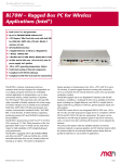
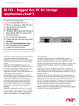
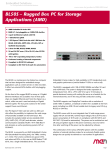
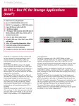
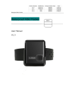
The BL70W is a fanless, maintenance-free box computer that has been designed for
independent use or as display computer electronics for wireless applications in
transportation, e.g. in trains, commercial vehicles, mobile machines or airplanes.
Four PCI Express® Mini Card slots each with dual SIM make it possible to flexibly
implement the whole range of wireless interfaces such as mobile service standards
GSM (2G), UMTS (3G), LTE (4G) and derivates and wireless communication
standards WLAN / Wi-Fi IEEE 802.11 and derivates. A GNSS interface supporting
positioning systems GPS and GLONASS complements the possibilities.
The BL70W is powered by an Intel® Core™ i7-3517UE CPU, running at 1.7 GHz.
Other processors of the 3rd generation Intel® Core™ i7 family can be used which
makes for high scalability in CPU (single/dual/quad core) performance.
The BL70W is equipped with 4 GB of DDR3 SDRAM and offers microSD™ card
and mSATA slots. A SATA hard-disk/solid-state drive can be installed within the
housing as an option. The system is designed for fanless operation at temperatures
from -40 to +70°C (+85°C for up to 10 minutes), its special aluminum housing with
cooling fins serves as a heatsink for the internal electronics and in this way provides
conduction cooling.
The BL70W supports up to two DisplayPort® interfaces with full HD resolution. In
addition, a multitude of other I/O is available at the front panel, including two
Gigabit Ethernet, two USB 2.0, variable slots for legacy serial I/O (e.g. RS232) or
CAN bus, general purpose inputs and relay outputs.
The BL70W comes with its own integrated 30W 24 VDC nom. (10 to 50.4 V) class
S2 wide-range power supply and is in compliance with EN 50155 and ISO 7637-2
(E-mark for automotive). The power can be switched on and off using an ignition
signal on the power connector, and a run-down time after switching off the power
can be adjusted by software.
The various CPU options with the available selection of external interfaces (realized
via separate graphics and I/O interface boards within the system) makes for an
extremely flexible system design that can quickly be tailored to a vast number of
applications.
MEN Mikro Elektronik GmbH
20BL70W00 E1 – 2014-12-09
2
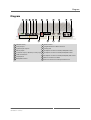
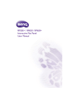
Diagram
Diagram
1
2
3
16
4
5
6
15
7
14
8
9
13
12
10
11
1 PSU (10V‐50.4V)
9 RS232 interface
2 2 relay outputs
10 2 Gigabit Ethernet on M12 connectors
3 2 photocoupler outputs
11 Earthing stud
4 6 binary inputs
12 SA‐Adapter connector for RS232, RS422/485 or IBIS
5 1 odometer input, 1 IBIS slave, 1 binary input 13 SA‐Adapter connector for RS232, RS422/485 or IBIS
6 2 USB 2.0 interfaces
14 SA‐Adapter connector for RS232, RS422/485, IBIS or CAN
7 2 DisplayPorts
15 Antenna connector for GNSS
8 RS422/485 interface
16 Antenna connectors for PCI Express Mini Cards
MEN Mikro Elektronik GmbH
20BL70W00 E1 – 2014-12-09
3
Technical Data
Technical Data
CPU
• Intel® Core™ i7-3517UE
- 1.7 GHz processor core frequency
- 2.8 GHz maximum turbo frequency
• Chipset
- QM77 Platform Controller Hub (PCH)
Memory
• 4 MB last level cache integrated in i7 processor
• 4 GB SDRAM system memory
- Soldered
- DDR3 with ECC support
- Up to 1066 MHz memory bus frequency
Mass Storage
• One microSD™ card slot
- Via USB 2.0
• One mSATA slot
- SATA Revision 2.x support
- Transfer rates up to 300 MB/s (3 Gbit/s)
• Serial ATA (SATA)
- One port for 2.5" hard-disk/solid-state drive mounted within the unit's
housing
- SATA Revision 2.x support
- Transfer rates up to 300 MB/s (3 Gbit/s)
Graphics
• Integrated in processor and chipset
• Maximum resolution: 2560 x 1600 pixels
• Via two DisplayPort® interfaces
Front I/O
• 2 DisplayPort® 1.1a interfaces
- AUX channels and hot plug detection
• 2 Gigabit Ethernet
- Via M12 connectors
- Electrically isolated
• 2 USB 2.0
- Via Series A connector
• 7 general purpose inputs
- Input voltage range from 0 V up to 154 V independent of the power supply
input voltage
- Input signal frequency max. 10 Hz
MEN Mikro Elektronik GmbH
20BL70W00 E1 – 2014-12-09
4
Technical Data
• 2 relay outputs
- Max. switching current 0..30 V: 2 A
- Max. switching current 30..72 V: 0.9 A
- Max. switching current 72..154 V: 0.3 A
- Max. switching voltage: 154 V
- Max. switching frequency: 1 Hz
- Minimum life time @ 1A, 30V, 20 cpm: 100.000
- Electrically isolated
• 2 photocouplers (shutters)
- Max. switching voltage: 154 V
- Max. current: 120 mA (switching and continuous)
• 1 odometer input
- For counting odometer pulses of a maximum frequency of 2 kHz
• 1 IBIS slave interface
- Baud rate up to 19.2 kBaud
- Electrically isolated
• GNSS interface
- Frequency band: GPS (L1), Glonass (L1, FDMA), Galileo (E1)
- Standards: NMEA, RTCM 104
- 32-channel GNSS architecture
- Accuracy: 1.5 m
- A-GPS
- Time-To-First-Fix – cold start: lower than 35 s
- Time-To-First-Fix – warm start / aided start: 1s
- Odometer input for GNSS receiver
• RS232
- D-Sub connector at front panel
- Data rates up to 115 200 bit/s
- 60-byte transmit/receive buffer
- Handshake lines: RTS, CTS
- Electrically isolated
• RS422/485
- D-Sub connector at front panel
- Full or half duplex
- Electrically isolated
• 2 SA-Adapter slots for legacy serial I/O
- For RS232, RS422/485 or IBIS master
• 1 SA-Adapter slot for RS232, RS422/485, IBIS or CAN
• 14 status LEDs
- 4 for Ethernet link and activity status
- 2 for general board status
- 8 user LEDs
MEN Mikro Elektronik GmbH
20BL70W00 E1 – 2014-12-09
5
Technical Data
4 PCI Express® Mini Card slots
• For functions such as
- Mobile service standards: GSM (2G), UMTS (3G), LTE (4G) and derivates
- Wireless communication: WLAN / WiFi IEEE 802.11 and derivates
• 2 SIM card slots for each PCI Express® Mini Card
• PCI Express® and USB interface
Real-Time Clock
• Buffered by Gold Cap for up to 72 h
Electrical Specifications
• Supply voltage:
- 24V and 36V nominal input voltage according to EN50155
- 24V nominal input voltage according to ISO 7637-2 (E-mark) requirements
- 10 to 50.4 V input voltage range
- EN 50155 power interruption class S2
• Power consumption: 24 W typ.
Mechanical Specifications
• Dimensions: Height 66 mm x Width 390 mm x Length 215 mm
• Weight: approx. 3 kg
Environmental Specifications
• Temperature range (operation):
- -40°C to 70°C (screened), with up to 85°C for 10 minutes according to class
Tx (EN 50155)
- Fanless operation
• Temperature range (storage): -40..+85°C
• Relative humidity (operation): max. 95% non-condensing
• Relative humidity (storage): max. 95% non-condensing
• Altitude: -300 m to +3,000 m
• Shock: 50 m/s², 30 ms (EN 61373)
• Vibration (function): 1 m/s², 5 Hz – 150 Hz (EN 61373)
• Vibration (lifetime): 7.9 m/s², 5 Hz – 150 Hz (EN 61373)
• Conformal coating of internal components
• Compliant to protection class IP43 according to DIN60529 when mounted with
connectors down
MTBF
• 198 000 h @ 40°C according to IEC/TR 62380 (RDF 2000)
MEN Mikro Elektronik GmbH
20BL70W00 E1 – 2014-12-09
6
Technical Data
Safety
• Flammability
- UL 94V-0
• Fire Protection
- EN 45545-2
• Electrical Safety
- EN 50153
- EN 50155
EMC Conformity (Automotive)
• ECE R10 (E-mark)
• ISO 10605 (ESD)
EMC Conformity (Railway)
• EN 50121-3-2
BIOS
• InsydeH2O™ UEFI Framework
Software Support
• Windows® 7
• Windows® Embedded Standard 7
• Linux
For more information on supported operating system versions and
drivers, please see the online data sheet.
MEN Mikro Elektronik GmbH
20BL70W00 E1 – 2014-12-09
7
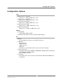
Configuration Options
Configuration Options
CPU
• Intel® Core™ i7-3517UE
- Dual Core, 1.7 GHz, 4 MB Cache, 17 W
• Intel® Core™ i3-3217UE
- Dual Core, 1.6 GHz, 3 MB Cache, 17 W
• Intel® Celeron® 1047UE
- Dual Core, 1.4 GHz, 2 MB Cache, 17 W
• Intel® Celeron® 927UE
- Single Core, 1.5 GHz, 1 MB Cache, 17 W
• Intel® Celeron® 827E
- Single Core, 1.4 GHz, 1.5 MB Cache, 17 W
Memory
• System RAM
- 2 GB, 4 GB, 8 GB or 16 GB
• SATA hard-disk/solid state drive (mounted within housing)
I/O
• Ethernet
- Two Fast Ethernet interfaces on two M12 connectors
• 1 HD audio
- HD audio codec
- Audio stereo in
- Audio stereo out
- SPDIF out
- Available via 9-pin D-Sub connector instead of one SA-Adapter
• Antenna connectors
- For functions like Wi-Fi, WIMAX, GSM/GPRS, UMTS, LTE in combination
with PCI Express® Mini Card(s)
- Reverse SMA connector
• SA-Adapter
- Two (when audio is used) or three slots for RS232, RS422/485, IBIS master
or CAN bus
MEN Mikro Elektronik GmbH
20BL70W00 E1 – 2014-12-09
8
Configuration Options
Electrical Specifications
• Input voltages of 48V, 72V and 110V can be implemented on request
- Acccording to EN 50155 class S2
As the product concept is very flexible, there are many other configuration
possibilities. Please contact our sales team if you do not find your required
function in the options. Please note that some of these options may only be
available for large volumes.
For available standard configurations see the online data sheet.
MEN Mikro Elektronik GmbH
20BL70W00 E1 – 2014-12-09
9
Product Safety
Product Safety
Electrostatic Discharge (ESD)
!
MEN Mikro Elektronik GmbH
20BL70W00 E1 – 2014-12-09
Computer boards and components contain electrostatic sensitive
devices. Electrostatic discharge (ESD) can damage components. To
protect the board and other components against damage from static
electricity, you should follow some precautions whenever you work on
your computer.
• Power down and unplug your computer system when working on the
inside.
• Hold components by the edges and try not to touch the IC chips,
leads, or circuitry.
• Use a grounded wrist strap before handling computer components.
• Place components on a grounded antistatic pad or on the bag that
came with the component whenever the components are separated
from the system.
• Only store the board in its original ESD-protected packaging. Retain
the original packaging in case you need to return the board to MEN
for repair.
10
About this Document
About this Document
This user manual is intended only for system developers and integrators, it is not
intended for end users.
It describes the hardware functions of the system and connection of peripheral
devices. It also provides additional information for special applications and
configurations of the system.
The manual does not include detailed information on individual components (data
sheets etc.). A list of literature is given in the appendix.
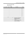
History
Issue
E1
MEN Mikro Elektronik GmbH
20BL70W00 E1 – 2014-12-09
Comments
First issue
Date
2014-12-09
11
About this Document
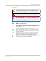
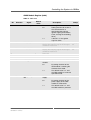
Conventions
Indicates important information or warnings concerning the use of
voltages that could lead to a hazardous situation which could result in
personal injury, or damage or destruction of the component.
!
Indicates important information or warnings concerning proper
functionality of the product described in this document.
The globe icon indicates a hyperlink that links directly to the Internet,
where the latest updated information is available.
When no globe icon is present, the hyperlink links to specific elements
and information within this document.
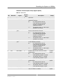
italics
Folder, file and function names are printed in italics.
bold
Bold type is used for emphasis.
mono
A monospaced font type is used for hexadecimal numbers, listings, C
function descriptions or wherever appropriate. Hexadecimal numbers
are preceded by "0x".
comment
Comments embedded into coding examples are shown in green text.
IRQ#
/IRQ
Signal names followed by a hashtag "#" or preceded by a forward
slash "/" indicate that this signal is either active low or that it becomes
active at a falling edge.
in/out
Signal directions in signal mnemonics tables generally refer to the
corresponding board or component, "in" meaning "to the board or
component", "out" meaning "from it the board or component".
Blue vertical lines in the outer margin indicate sections where changes
have been made to this version of the document.
MEN Mikro Elektronik GmbH
20BL70W00 E1 – 2014-12-09
12
About this Document
Legal Information
Changes
MEN Mikro Elektronik GmbH ("MEN") reserves the right to make changes without further notice to any products
herein.
Warranty, Guarantee, Liability
MEN makes no warranty, representation or guarantee of any kind regarding the suitability of its products for any
particular purpose, nor does MEN assume any liability arising out of the application or use of any product or
circuit, and specifically disclaims any and all liability, including, without limitation, consequential or incidental
damages. TO THE EXTENT APPLICABLE, SPECIFICALLY EXCLUDED ARE ANY IMPLIED
WARRANTIES ARISING BY OPERATION OF LAW, CUSTOM OR USAGE, INCLUDING WITHOUT
LIMITATION, THE IMPLIED WARRANTIES OF MERCHANTABILITY AND FITNESS FOR A
PARTICULAR PURPOSE OR USE. In no event shall MEN be liable for more than the contract price for the
products in question. If buyer does not notify MEN in writing within the foregoing warranty period, MEN shall
have no liability or obligation to buyer hereunder.
The publication is provided on the terms and understanding that:
1. MEN is not responsible for the results of any actions taken on the basis of information in the publication, nor
for any error in or omission from the publication; and
2. MEN is not engaged in rendering technical or other advice or services.
MEN expressly disclaims all and any liability and responsibility to any person, whether a reader of the publication
or not, in respect of anything, and of the consequences of anything, done or omitted to be done by any such person
in reliance, whether wholly or partially, on the whole or any part of the contents of the publication.
Conditions for Use, Field of Application
The correct function of MEN products in mission-critical and life-critical applications is limited to the
environmental specification given for each product in the technical user manual. The correct function of MEN
products under extended environmental conditions is limited to the individual requirement specification and
subsequent validation documents for each product for the applicable use case and has to be agreed upon in writing
by MEN and the customer. Should the customer purchase or use MEN products for any unintended or
unauthorized application, the customer shall indemnify and hold MEN and its officers, employees, subsidiaries,
affiliates, and distributors harmless against all claims, costs, damages, and expenses, and reasonable attorney fees
arising out of, directly or indirectly, any claim or personal injury or death associated with such unintended or
unauthorized use, even if such claim alleges that MEN was negligent regarding the design or manufacture of the
part. In no case is MEN liable for the correct function of the technical installation where MEN products are a part
of.
Trademarks
All products or services mentioned in this publication are identified by the trademarks, service marks, or product
names as designated by the companies which market those products. The trademarks and registered trademarks
are held by the companies producing them. Inquiries concerning such trademarks should be made directly to those
companies.
Conformity
MEN products are no ready-made products for end users. They are tested according to the standards given in the
Technical Data and thus enable you to achieve certification of the product according to the standards applicable in
your field of application.
MEN Mikro Elektronik GmbH
20BL70W00 E1 – 2014-12-09
13
About this Document
RoHS
Since July 1, 2006 all MEN standard products comply with RoHS legislation.
Since January 2005 the SMD and manual soldering processes at MEN have already been completely lead-free.
Between June 2004 and June 30, 2006 MEN’s selected component suppliers have changed delivery to RoHScompliant parts. During this period any change and status was traceable through the MEN ERP system and the
boards gradually became RoHS-compliant.
WEEE Application
The WEEE directive does not apply to fixed industrial plants and tools. The compliance is the responsibility of the
company which puts the product on the market, as defined in the directive; components and sub-assemblies are
not subject to product compliance.
In other words: Since MEN does not deliver ready-made products to end users, the WEEE directive is not
applicable for MEN. Users are nevertheless recommended to properly recycle all electronic boards which have
passed their life cycle.
Nevertheless, MEN is registered as a manufacturer in Germany. The registration number can be provided on
request.
Copyright © 2014 MEN Mikro Elektronik GmbH. All rights reserved.
Germany
MEN Mikro Elektronik GmbH
Neuwieder Straße 3-7
90411 Nuremberg
Phone +49-911-99 33 5-0
Fax +49-911-99 33 5-901
E-mail [email protected]
www.men.de
MEN Mikro Elektronik GmbH
20BL70W00 E1 – 2014-12-09
France
MEN Mikro Elektronik SAS
18, rue René Cassin
ZA de la Châtelaine
74240 Gaillard
Phone +33 (0) 450-955-312
Fax +33 (0) 450-955-211
E-mail [email protected]
www.men-france.fr
USA
MEN Micro Inc.
860 Penllyn Blue Bell Pike
Blue Bell, PA 19422
Phone (215) 542-9575
Fax (215) 542-9577
E-mail [email protected]
www.menmicro.com
14
Contents
Contents
1 Product Description . . . . . . . . . . . . . . . . . . . . . . . . . . . . . . . . . . . . . . . . . . . .
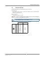
1.1 Overview . . . . . . . . . . . . . . . . . . . . . . . . . . . . . . . . . . . . . . . . . . . . . . .
1.1.1
External Interfaces . . . . . . . . . . . . . . . . . . . . . . . . . . . . . . . .
1.1.2
Map of the System . . . . . . . . . . . . . . . . . . . . . . . . . . . . . . . .
1.2 Block Diagram. . . . . . . . . . . . . . . . . . . . . . . . . . . . . . . . . . . . . . . . . . .
1.3 Product Identification . . . . . . . . . . . . . . . . . . . . . . . . . . . . . . . . . . . . .
19
19
19
20
21
22
2 Getting Started . . . . . . . . . . . . . . . . . . . . . . . . . . . . . . . . . . . . . . . . . . . . . . . .
2.1 Unpacking the System . . . . . . . . . . . . . . . . . . . . . . . . . . . . . . . . . . . . .
2.2 Configuring the Hardware . . . . . . . . . . . . . . . . . . . . . . . . . . . . . . . . . .
2.2.1
Handling Internal Components . . . . . . . . . . . . . . . . . . . . . . .
2.2.2
Opening the BL70W . . . . . . . . . . . . . . . . . . . . . . . . . . . . . . .
2.2.3
Installing PCI Express Mini Cards . . . . . . . . . . . . . . . . . . . .
2.2.4
Installing SA-Adapters. . . . . . . . . . . . . . . . . . . . . . . . . . . . .
2.2.5
Installing a microSD Card. . . . . . . . . . . . . . . . . . . . . . . . . . .
2.2.6
Installing an mSATA Drive . . . . . . . . . . . . . . . . . . . . . . . . . .
2.3 Mounting the BL70W . . . . . . . . . . . . . . . . . . . . . . . . . . . . . . . . . . . . .
2.3.1
Installing the BL70W in a 19" Rack . . . . . . . . . . . . . . . . . . .
2.4 Connecting an Earthing Cable. . . . . . . . . . . . . . . . . . . . . . . . . . . . . . .
2.5 Electrical Connection . . . . . . . . . . . . . . . . . . . . . . . . . . . . . . . . . . . . .
2.6 Starting up the System. . . . . . . . . . . . . . . . . . . . . . . . . . . . . . . . . . . . .
2.7 Installing Operating System Software. . . . . . . . . . . . . . . . . . . . . . . . .
2.8 Installing Driver Software . . . . . . . . . . . . . . . . . . . . . . . . . . . . . . . . . .
23
23
23
25
25
27
29
31
31
33
34
36
36
37
37
37
3 Functional Description . . . . . . . . . . . . . . . . . . . . . . . . . . . . . . . . . . . . . . . . . .
3.1 Power Supply. . . . . . . . . . . . . . . . . . . . . . . . . . . . . . . . . . . . . . . . . . . .
3.1.1
Ignition . . . . . . . . . . . . . . . . . . . . . . . . . . . . . . . . . . . . . . . . .
3.2 Real-Time Clock . . . . . . . . . . . . . . . . . . . . . . . . . . . . . . . . . . . . . . . . .
3.3 Processor Core. . . . . . . . . . . . . . . . . . . . . . . . . . . . . . . . . . . . . . . . . . .
3.3.1
Intel Active Management Technology (AMT) . . . . . . . . . . .
3.3.2
Thermal Considerations . . . . . . . . . . . . . . . . . . . . . . . . . . . .
3.4 Memory and Mass Storage . . . . . . . . . . . . . . . . . . . . . . . . . . . . . . . . .
3.4.1
DRAM System Memory . . . . . . . . . . . . . . . . . . . . . . . . . . . .
3.4.2
Boot Flash . . . . . . . . . . . . . . . . . . . . . . . . . . . . . . . . . . . . . . .
3.4.3
microSD Card Slot . . . . . . . . . . . . . . . . . . . . . . . . . . . . . . . .
3.4.4
mSATA Slot. . . . . . . . . . . . . . . . . . . . . . . . . . . . . . . . . . . . . .
3.4.5
SATA Hard Disk (Optional) . . . . . . . . . . . . . . . . . . . . . . . . .
3.5 Graphics. . . . . . . . . . . . . . . . . . . . . . . . . . . . . . . . . . . . . . . . . . . . . . . .
3.5.1
DisplayPort Interfaces. . . . . . . . . . . . . . . . . . . . . . . . . . . . . .
3.5.2
Other Graphics Interfaces . . . . . . . . . . . . . . . . . . . . . . . . . . .
3.6 USB Interface . . . . . . . . . . . . . . . . . . . . . . . . . . . . . . . . . . . . . . . . . . .
3.7 Ethernet Interface . . . . . . . . . . . . . . . . . . . . . . . . . . . . . . . . . . . . . . . .
3.7.1
Ethernet Status LEDs . . . . . . . . . . . . . . . . . . . . . . . . . . . . . .
38
38
39
41
41
41
42
43
43
43
43
43
43
44
44
45
46
47
48
MEN Mikro Elektronik GmbH
20BL70W00 E1 – 2014-12-09
15
Contents
3.8 HD Audio (Optional). . . . . . . . . . . . . . . . . . . . . . . . . . . . . . . . . . . . . .
3.9 Status and User LEDs . . . . . . . . . . . . . . . . . . . . . . . . . . . . . . . . . . . . .
3.9.1
Status LED . . . . . . . . . . . . . . . . . . . . . . . . . . . . . . . . . . . . . .
3.10 Serial Interfaces . . . . . . . . . . . . . . . . . . . . . . . . . . . . . . . . . . . . . . . . . .
3.10.1 RS232 Interface. . . . . . . . . . . . . . . . . . . . . . . . . . . . . . . . . . .
3.10.2 RS422/485 Interface . . . . . . . . . . . . . . . . . . . . . . . . . . . . . . .
3.11 Serial Interfaces via SA-Adapter. . . . . . . . . . . . . . . . . . . . . . . . . . . . .
3.12 PCI Express Mini Card Interface. . . . . . . . . . . . . . . . . . . . . . . . . . . . .
3.12.1 Connection of PCI Express Mini Cards . . . . . . . . . . . . . . . .
3.13 6-Pin Headers . . . . . . . . . . . . . . . . . . . . . . . . . . . . . . . . . . . . . . . . . . .
3.13.1 Relay Outputs . . . . . . . . . . . . . . . . . . . . . . . . . . . . . . . . . . . .
3.13.2 Binary Inputs. . . . . . . . . . . . . . . . . . . . . . . . . . . . . . . . . . . . .
3.13.3 IBIS . . . . . . . . . . . . . . . . . . . . . . . . . . . . . . . . . . . . . . . . . . . .
3.13.4 Photocouplers . . . . . . . . . . . . . . . . . . . . . . . . . . . . . . . . . . . .
3.13.5 Odometer Input . . . . . . . . . . . . . . . . . . . . . . . . . . . . . . . . . . .
3.14 GNSS . . . . . . . . . . . . . . . . . . . . . . . . . . . . . . . . . . . . . . . . . . . . . . . . . .
3.14.1 Updating the GNSS Module’s Firmware . . . . . . . . . . . . . . .
49
50
51
52
52
53
55
56
56
59
60
61
61
61
62
63
63
4 Controlling the System via SMBus . . . . . . . . . . . . . . . . . . . . . . . . . . . . . . . . 65
4.1 SMBus Overview. . . . . . . . . . . . . . . . . . . . . . . . . . . . . . . . . . . . . . . . . 65
4.2 SMBus Register Description . . . . . . . . . . . . . . . . . . . . . . . . . . . . . . . . 66
5 Using the BL70W with MDIS5 Software . . . . . . . . . . . . . . . . . . . . . . . . . . . 74
5.1 GPIO Controller Instance 1 . . . . . . . . . . . . . . . . . . . . . . . . . . . . . . . . . 74
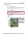
6 Maintenance . . . . . . . . . . . . . . . . . . . . . . . . . . . . . . . . . . . . . . . . . . . . . . . . . . 76
6.1 Cleaning the System . . . . . . . . . . . . . . . . . . . . . . . . . . . . . . . . . . . . . . 76
6.2 Fuse Protection . . . . . . . . . . . . . . . . . . . . . . . . . . . . . . . . . . . . . . . . . . 76
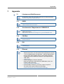
7 Appendix . . . . . . . . . . . . . . . . . . . . . . . . . . . . . . . . . . . . . . . . . . . . . . . . . . . . .
7.1 Literature and Web Resources . . . . . . . . . . . . . . . . . . . . . . . . . . . . . . .
7.1.1
GNSS . . . . . . . . . . . . . . . . . . . . . . . . . . . . . . . . . . . . . . . . . .
7.1.2
Accelerometer / Magnetometer LSM303DLM. . . . . . . . . . .
7.1.3
CAN Bus . . . . . . . . . . . . . . . . . . . . . . . . . . . . . . . . . . . . . . . .
7.1.4
DVI . . . . . . . . . . . . . . . . . . . . . . . . . . . . . . . . . . . . . . . . . . . .
7.1.5
Ethernet . . . . . . . . . . . . . . . . . . . . . . . . . . . . . . . . . . . . . . . . .
7.1.6
HD Audio . . . . . . . . . . . . . . . . . . . . . . . . . . . . . . . . . . . . . . .
7.1.7
PCI Express Mini Card . . . . . . . . . . . . . . . . . . . . . . . . . . . . .
7.1.8
USB . . . . . . . . . . . . . . . . . . . . . . . . . . . . . . . . . . . . . . . . . . . .
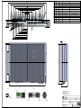
7.2 Dimensions of the BL70W Box PC . . . . . . . . . . . . . . . . . . . . . . . . . .
MEN Mikro Elektronik GmbH
20BL70W00 E1 – 2014-12-09
77
77
77
77
77
77
77
78
78
78
78
16
Figures
Figure 1. The BL70W - overview . . . . . . . . . . . . . . . . . . . . . . . . . . . . . . . . . . . . 19
Figure 2. The BL70W - front interfaces . . . . . . . . . . . . . . . . . . . . . . . . . . . . . . . 19
Figure 3. Map of the system – view of the BL70W interior . . . . . . . . . . . . . . . . 20
Figure 4. Block diagram. . . . . . . . . . . . . . . . . . . . . . . . . . . . . . . . . . . . . . . . . . . . 21
Figure 5. Label giving the product’s article number, revision and serial number 22
Figure 6. Screw positions on the bottom of the BL70W . . . . . . . . . . . . . . . . . . . 25
Figure 7. Screw positions at the rear of the BL70W . . . . . . . . . . . . . . . . . . . . . . 26
Figure 8. Installing a PCI Express Mini card. . . . . . . . . . . . . . . . . . . . . . . . . . . . 27
Figure 9. 10-pin SA-Adapter connectors (highlighted in red) . . . . . . . . . . . . . . . 30
Figure 10. Mounting distances required for the box PC . . . . . . . . . . . . . . . . . . . . 33
Figure 11. PSU connector at BL70W front . . . . . . . . . . . . . . . . . . . . . . . . . . . . . . 38
Figure 12. Connection of power pins from PSU . . . . . . . . . . . . . . . . . . . . . . . . . . 39
Figure 13. Ignition behavior. . . . . . . . . . . . . . . . . . . . . . . . . . . . . . . . . . . . . . . . . . 39
Figure 14. Ignition and watchdog state diagram . . . . . . . . . . . . . . . . . . . . . . . . . . 40
Figure 15. Position of Ethernet LEDs at BL70W front (highlighted in red) . . . . . 48
Figure 16. Status and user LEDs on the BL70W’s front panel (highlighted in red) .
50
Figure 17. Position of serial interfaces on BL70W front. . . . . . . . . . . . . . . . . . . . 55
Figure 18. Spring cage terminal blocks . . . . . . . . . . . . . . . . . . . . . . . . . . . . . . . . . 59
Figure 19. Relay switch - 3 lines (default state) . . . . . . . . . . . . . . . . . . . . . . . . . . 60
Figure 20. Photocouplers (shutters) - 2 lines . . . . . . . . . . . . . . . . . . . . . . . . . . . . . 61
Figure 21. TESEOII X-Loader settings . . . . . . . . . . . . . . . . . . . . . . . . . . . . . . . . . 64
Figure 22. SMBus overview . . . . . . . . . . . . . . . . . . . . . . . . . . . . . . . . . . . . . . . . . 65
Figure 23. Position of the fuse in the interior of the BL70W (highlighted in red) 76
MEN Mikro Elektronik GmbH
20BL70W00 E1 – 2014-12-09
17
Tables
Table 1.
Table 2.
Table 3.
Table 4.
Table 5.
Table 6.
Table 7.
Table 8.
Table 9.
Table 10.
Table 11.
Table 12.
Table 13.
Table 14.
Table 15.
Table 16.
Table 17.
Table 18.
Table 19.
Table 20.
Table 21.
Table 22.
Table 23.
Table 24.
Table 25.
Table 26.
Table 27.
Table 28.
Table 29.
Table 30.
Table 31.
Table 32.
Table 33.
Table 34.
Table 35.
Table 36.
Table 37.
Table 38.
MEN Mikro Elektronik GmbH
20BL70W00 E1 – 2014-12-09
Pin assignment of PSU connector . . . . . . . . . . . . . . . . . . . . . . . . . . . . 38
Processor core options on BL70W . . . . . . . . . . . . . . . . . . . . . . . . . . . . 41
Pin assignment of 20-pin DisplayPort connector . . . . . . . . . . . . . . . . . 44
Signal mnemonics of 20-pin DisplayPort connector . . . . . . . . . . . . . . 45
Pin assignment of USB front-panel connectors . . . . . . . . . . . . . . . . . . 46
Signal mnemonics of USB front-panel connectors . . . . . . . . . . . . . . . 46
Pin assignment of Ethernet front-panel connectors . . . . . . . . . . . . . . . 47
Signal mnemonics of Ethernet front-panel connectors. . . . . . . . . . . . . 48
Ethernet status LEDs . . . . . . . . . . . . . . . . . . . . . . . . . . . . . . . . . . . . . . 48
Pin assignment of the HD audio interface . . . . . . . . . . . . . . . . . . . . . . 49
Signal mnemonics of the HD audio interface. . . . . . . . . . . . . . . . . . . . 49
Status and user LEDs on the BL70W. . . . . . . . . . . . . . . . . . . . . . . . . . 50
Error codes signaled by board management controller via LED flashes .
51
Pin assignment of 9-pin D-Sub connector for RS232 . . . . . . . . . . . . . 52
Signal mnemonics of RS232 connector . . . . . . . . . . . . . . . . . . . . . . . . 52
Pin assignment of the 9-pin D-Sub receptacle – full duplex . . . . . . . . 53
Signal mnemonics of RS422/485 interface – full duplex. . . . . . . . . . . 53
Pin assignment of the 9-pin D-Sub receptacle – half duplex . . . . . . . . 54
Signal mnemonics of RS422/485 interface – half duplex . . . . . . . . . . 54
Pin assignment of 52-pin PCI Express Mini Card connector. . . . . . . . 57
Signal mnemonics of 52-pin PCI Express Mini Card connector . . . . . 58
Pin assignment of relay out connector . . . . . . . . . . . . . . . . . . . . . . . . . 59
Pin assignment of opt out connector. . . . . . . . . . . . . . . . . . . . . . . . . . . 59
Pin assignment of binary I/O connector 1 . . . . . . . . . . . . . . . . . . . . . . 59
Pin assignment of binary I/O connector 2 . . . . . . . . . . . . . . . . . . . . . . 59
Signal mnemonics of spring cage terminal block . . . . . . . . . . . . . . . . 60
Odometer switching voltage levels. . . . . . . . . . . . . . . . . . . . . . . . . . . . 62
Odometer default / reset states . . . . . . . . . . . . . . . . . . . . . . . . . . . . . . . 62
SMB address space. . . . . . . . . . . . . . . . . . . . . . . . . . . . . . . . . . . . . . . . 66
SMB 0x4E . . . . . . . . . . . . . . . . . . . . . . . . . . . . . . . . . . . . . . . . . . . . . . 67
SMB 0x46. . . . . . . . . . . . . . . . . . . . . . . . . . . . . . . . . . . . . . . . . . . . . . . 68
SMB 0x44. . . . . . . . . . . . . . . . . . . . . . . . . . . . . . . . . . . . . . . . . . . . . . . 69
SMB 0x42. . . . . . . . . . . . . . . . . . . . . . . . . . . . . . . . . . . . . . . . . . . . . . . 71
SMB 0x40. . . . . . . . . . . . . . . . . . . . . . . . . . . . . . . . . . . . . . . . . . . . . . . 72
Chameleon table . . . . . . . . . . . . . . . . . . . . . . . . . . . . . . . . . . . . . . . . . . 74
Functions of GPIO controller instance 1 . . . . . . . . . . . . . . . . . . . . . . . 74
Interface Multiplexer 0 truth table:. . . . . . . . . . . . . . . . . . . . . . . . . . . . 75
Interface Multiplexer 1 truth table . . . . . . . . . . . . . . . . . . . . . . . . . . . . 75
18
Product Description
1
Product Description
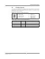
1.1
Overview
This chapter gives an overview of the box PC.
Figure 1. The BL70W - overview
1.1.1
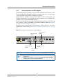
External Interfaces
The following picture shows the BL70W front without antennas and flexible SAAdapters.
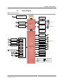
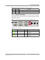
Figure 2. The BL70W - front interfaces
1
2
3
16
4
5
6
15
7
14
8
9
13
12
10
11
1 PSU (10V‐50.4V)
9 RS232 interface
2 2 relay outputs
10 2 Gigabit Ethernet on M12 connectors
3 2 photocoupler outputs
11 Earthing stud
4 6 binary inputs
12 SA‐Adapter connector for RS232, RS422/485 or IBIS
5 1 odometer input, 1 IBIS slave, 1 binary input 13 SA‐Adapter connector for RS232, RS422/485 or IBIS
6 2 USB 2.0 interfaces
14 SA‐Adapter connector for RS232, RS422/485, IBIS or CAN
7 2 DisplayPorts
15 Antenna connector for GNSS
8 RS422/485 interface
16 Antenna connectors for PCI Express Mini Cards
MEN Mikro Elektronik GmbH
20BL70W00 E1 – 2014-12-09
19
Product Description
1.1.2
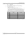
Map of the System
Figure 3. Map of the system – view of the BL70W interior
1
2
2
3
4
5
6
23
22
21
7
20
19
7
18
2
17
3
16
15
SATA
8
14
2
7
13
7
12
2
11
10
9
24
AE83 I/O Board
2 microSIM slot
3 Board‐to‐board connector
4 SC24 CPU Board
13 1 odometer input, 2 IBIS channels, 1 binary input
5 mSATA slot
6 SD card slot (on board bottom)
17
7 PCIe Mini Card slot
8 Connector for optional SATA disk
19 SA‐Adapter connector for RS232, RS422/485 or IBIS
9 PSU connector
21 SA‐Adapter connector for RS232, RS422/485 or IBIS
10 2 relay outputs
22 Gigabit Ethernet 2 on M12 connector
11 2 optocoupler outputs
23 Gigabit Ethernet 1 on M12 connector
12 6 binary inputs
24
1
MEN Mikro Elektronik GmbH
20BL70W00 E1 – 2014-12-09
14 2 USB 2.0 interfaces
15 DisplayPort1
16 SA‐Adapter connector for RS232, RS422/485 or CAN
DisplayPort2
18 RS422/485 interface
20 RS232 interface
Fuse for protecting the system
20
Product Description
1.2
Block Diagram
Figure 4. Block diagram
4 GB DDR3 SDRAM
Power Supply
F
6 SIM Card Slots
PCIe
F
DisplayPort 1
USB
3 PCI Express® Mini Card Slots
F
6 Antenna Slots
Intel® Core™
Processor
F
DisplayPort 2
1 PCI Express® Mini Card Slot
USB
F
2 Antenna Slots
F
2 SIM Card Slots
PCIe
F
1 IBIS Slave
UART
F
1 RS232
UART
F
1 RS422/RS485
UART
FPGA
GPIO
F
1 CAN SA‐Adapter
F
F
SA
SA
B
B
Intel® Platform Controller Hub
QM77
2 x 10/100/1000
Base‐T Ethernet Controller
F
HD Audio
F
2 x USB 2.0
F
1 GPS
F
7 GPIs
F
2 Photo Couplers
F
1 Odometer Input
F
2 Relay Outputs
F
CAN
USB
SD Card Slot
SPI
Boot Flash
SATA
mSATA Slot
UART
UART
F
Front connector B On‐board connector
Options
MEN Mikro Elektronik GmbH
20BL70W00 E1 – 2014-12-09
1 Antenna Slot
SA SA‐Adapter
21
Product Description
1.3
Product Identification
MEN user documentation may describe several different models and/or design
revisions of the BL70W. You can find information on the article number, the design
revision and the serial number on a label attached to the chassis.
• Article number: Gives the product’s family and model. This is also MEN’s
ordering number. To be complete it must have 9 characters.
• Revision number: Gives the design revision of the product.
• Serial number: Unique identification assigned during production.
If you need support, you should communicate these numbers to MEN.
Figure 5. Label giving the product’s article number, revision and serial number
Complete article number
Article No.:
09BL0:00
Serial No.:
000002
Rev. 00.00.00
Serial number
Revision number
MEN Mikro Elektronik GmbH
20BL70W00 E1 – 2014-12-09
22
Getting Started
2
Getting Started
2.1
Unpacking the System
After unpacking, check whether there are any transport or other damages on the
system.
2.2
Configuring the Hardware
Check your hardware requirements before mounting the BL70W, since most
modifications are difficult or even impossible to do when the box PC is mounted.
The following check list gives an overview on what you might want to configure.
For installing the components mentioned below, the BL70W has to be opened.
See Chapter 2.2.1 Handling Internal Components on page 25 and Chapter 2.2.2
Opening the BL70W on page 25.
PCI Express Mini Cards
Four PCI Express Mini Cards for wireless functions can be installed in the
BL70W. MEN offers an LTE (4G) and a WLAN card as an accessory.
Refer to Chapter 2.2.3 Installing PCI Express Mini Cards on page 27 and
Chapter 3.12 PCI Express Mini Card Interface on page 56 for details on the
installation and functionality of the PCI Express Mini Cards.
Antenna connectors
Nine antennas can be installed at the BL70W’s front panel (such as SMA,
reverse SMA, QMA, FME etc). MEN offers an HF antenna cable with U.FL
connector to RP-SMA connector as an accessory.
Refer to Chapter 2.2.3 Installing PCI Express Mini Cards on page 27 and for
details on the installation of the antenna connectors.
microSD card
The BL70W is equipped with one microSD card slot. MEN provides a 4 GB
microSD card as an accessory (other memory sizes are available on request).
Refer to Chapter 2.2.5 Installing a microSD Card on page 31 for information
on how to install the SD card.
mSATA disk
The BL70W is equipped with one mSATA disk slot. MEN provides an 8 GB
mSATA disk as an accessory (other memory sizes are available on request).
Refer to Chapter 2.2.6 Installing an mSATA Drive on page 31 for information
on how to install the mSATA disk.
MEN Mikro Elektronik GmbH
20BL70W00 E1 – 2014-12-09
23
Getting Started
UART, GPS, IBIS extension through MEN standard SA-Adapters
The board provides three 10-pin I/O connectors for connection of three SAAdapters for UART, GPS, IBIS or CAN functionality. MEN provides a range of
standard adapters with different functionality.
Refer to Chapter 2.2.4 Installing SA-Adapters on page 29 and Chapter 3.10
Serial Interfaces on page 52 for details on the installation and functionality of
the SA-Adapters.
See MEN’s website for information on how to order the accessories.
MEN Mikro Elektronik GmbH
20BL70W00 E1 – 2014-12-09
24
Getting Started
2.2.1
Handling Internal Components
•
!
2.2.2
•
Switch off or unplug the power supply of the box PC before working
on internal components.
Please observe the instructions concerning electrostatic discharge
whenever you work on the inside of the computer system. See
Chapter Electrostatic Discharge (ESD) on page 10.
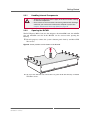
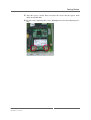
Opening the BL70W
The PCI Express Mini Cards, the SA-Adapters, the microSIM cards, the mSATA
slot and microSD card slot of the BL70W can be accessed after opening the
housing.
For this purpose, remove the system’s bottom panel fixed by ten M3x8 TX8
Torx screws.
Figure 6. Screw positions on the bottom of the BL70W
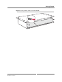
To access the SD card slot, remove the rear panel of the unit fixed by six M3x8
TX8 Torx screws.
MEN Mikro Elektronik GmbH
20BL70W00 E1 – 2014-12-09
25
Getting Started
Figure 7. Screw positions at the rear of the BL70W
MEN Mikro Elektronik GmbH
20BL70W00 E1 – 2014-12-09
26
Getting Started
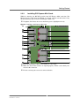
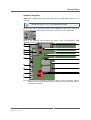
2.2.3
Installing PCI Express Mini Cards
Within its housing, the BL70W provides four PCI Express Mini card slots. The
M2.5x8 screws required for installation are already screwed onto the board. Carry
out the following steps to install a PCI Express Mini card.
Untighten and remove the screws from the spacers (highlighted in red).
Figure 8. Installing a PCI Express Mini card
21
20
19
18
17
16
15
SATA
14
13
12
11
Insert the PCI Express Mini card carefully at a 30° angle.
Make sure that all the contacts are aligned properly and the card is firmly connected to the connector.
Fix the card using the two screws removed before.
MEN Mikro Elektronik GmbH
20BL70W00 E1 – 2014-12-09
27
Getting Started
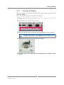
Antenna Connectors
MEN offers an HF antenna cable with U.FL connector to RP-SMA connector as an
accessory.
Please see the MEN website for ordering information.
Before being able to install the antenna on the BL70W’s front panel, you have to
break out the cover of the antenna slot, using a screw driver or a similar tool.
There is one mounting clip for fixing the antenna cable on the BL70W’s PCB
(highlighted in red in the following drawing).
19
18
17
16
15
SATA
14
13
12
11
10
Note: There is only one position in which the antenna can be completely inserted
into the front panel slot. When properly inserted the antenna is fixed and cannot be turned anymore.
MEN Mikro Elektronik GmbH
20BL70W00 E1 – 2014-12-09
28
Getting Started
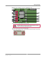
2.2.4
Installing SA-Adapters
Three SA-Adapters can be mounted in the BL70W on the 10-pin receptacle for slots
X10, X11 and X12.
Carry out the following steps to install the SA-Adapters:
Remove the front panel as described in Chapter 2.2.2 Opening the BL70W on
page 25.
Break out the covers of the front panel slots.
Make sure that the adapter matches the standard dimensions for SA-Adapters.
See also installation hints in the adapter’s user manual or the list of
compatible accessories in the BL70W data sheet on MEN’s website.
Remove the two front panel screws of the SA-Adapter.
Carefully align the SA-Adapter connectors with the 10-pin connectors on the
BL70W.
MEN Mikro Elektronik GmbH
20BL70W00 E1 – 2014-12-09
29
Getting Started
Figure 9. 10-pin SA-Adapter connectors (highlighted in red)
7
7
2
3
SATA
8
Press the SA-Adapter firmly onto the BL70W.
!
Carefully align the front panel with the front connectors and the
LEDs. Be careful not to damage the LEDs.
Screw the front panel back onto the BL70W.
Screw the SA-Adapter tightly to the BL70W front panel using the two pan-head
screws removed before.
MEN Mikro Elektronik GmbH
20BL70W00 E1 – 2014-12-09
30
Getting Started
2.2.5
Installing a microSD Card
Within its housing, the BL70W provides one microSD card slot. Carry out the
following steps to install a microSD card.
The microSD card slot is positioned at the edge of the system, wedged between
the PCB and the top of the housing.
Insert the microSD card into the slot with the contacts facing to the PCB and
the cut edge to the right side.
Make sure that it clicks into place properly.
To eject the microSD card, push it until it springs out, then simply pull it out.
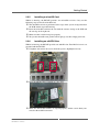
2.2.6
Installing an mSATA Drive
Within its housing, the BL70W provides one mSATA slot. Two M2.5x8 screws are
provided with the BL70W.
Untighten and remove the screws from the spacers (highlighted in red).
Insert the mSATA drive carefully at a 30° angle.
Make sure that all the contacts are aligned properly and the card is firmly connected to the mSATA connector.
MEN Mikro Elektronik GmbH
20BL70W00 E1 – 2014-12-09
31
Getting Started
Align the spacers and the holes and insert the screws into the spacers from
above the mSATA disk.
Fix the card by tightening the screws (highlighted in red in the following drawing).
MEN Mikro Elektronik GmbH
20BL70W00 E1 – 2014-12-09
32
Getting Started
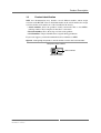
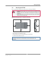
2.3
Mounting the BL70W
Please consider the following instructions when installing the BL70W:
•
!
•
•
Do not install the system near any heat sources (e.g. radiators, heat
registers).
Keep the system away from liquids. Avoid exposure to dripping or
splashing.
Keep a free space of 15 cm around the housing to ensure cooling
(except on the mounting side).
Figure 10. Mounting distances required for the box PC
15cm
15cm
15cm
15cm
15cm
15cm
15cm
• The connector side should face down.
• The BL70W provides four mounting holes for installation.
• Use M5 countersink head screws.
See Chapter 7.2 Dimensions of the BL70W Box PC on page 78 for the exact
dimensions of the box PC and the positions of the mounting holes and
connectors.
MEN Mikro Elektronik GmbH
20BL70W00 E1 – 2014-12-09
33
Getting Started
2.3.1
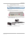
Installing the BL70W in a 19" Rack
MEN offers a 1.5U mounting kit which makes it possible to install the BL70W in a
19" rack (05BL01-00).
Please see MEN’s website for more information.
Remove the BL70W’s bottom panel as described in Chapter 2.2.2 Opening the
BL70W on page 25.
Remove five of the screws fastening the front panel (highlighted in red in the
following picture). Do not remove the front panel.
Install the two heats sinks supplied with the kit at the sides of the BL70W using
four M2.5x10 TX8 Torx screws for each heat sink. The screws are included in
the delivery of the 05BL01-00 kit.
Insert the box PC into the opening in the kit’s front panel.
MEN Mikro Elektronik GmbH
20BL70W00 E1 – 2014-12-09
34
Getting Started
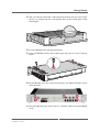
Take care that the small studs at the bottom of the front and rear panel of the
box PC are aligned with the corresponding holes in the bottom plate of the
mounting kit.
Press the BL70W down onto the bottom plate.
Screw the BL70W onto the kit’s bottom plate using the ten screws removed
before.
Fix the BL70W at the kit’s front panel using the five M3x8 TX8 Torx screws
removed before.
Fasten the BL70W in the frame in the 19" switching cabinet using four M6x16
screws.
MEN Mikro Elektronik GmbH
20BL70W00 E1 – 2014-12-09
35
Getting Started
2.4
Connecting an Earthing Cable
The BL70W features an earthing stud on the right side of the front panel (see Figure
2, The BL70W - front interfaces on page 19). A protective earth connection is
essential for the system to meet its EMC specifications.
!
An earthing cable has to be connected to the earthing stud before any
other connections! For disassembling the system, the earthing cable
has to be detached last.
Carry out the following steps to connect an earthing cable:
Take an earthing cable with a cross section of at least 0.75 mm².
Slide the cable onto the stud between the washer and the lock washer as indicated in the following picture:
Fasten the cable by tightening the nut.
2.5
Electrical Connection
•
!
•
•
•
•
•
•
•
MEN Mikro Elektronik GmbH
20BL70W00 E1 – 2014-12-09
Ensure that the box PC is completely configured and mounted
before connecting and applying power to the system.
Implement a readily accessible disconnect device external to the
box PC for complying with the EN 60950-1 standard.
Make sure that the voltage of the power supply conforms with the
voltage on the type plate.
Ensure that the power supply (power socket) is grounded correctly
and that the power cable is intact and undamaged.
Do not switch on the system if there are damages on the power
cable or plug.
Use power cables which are approved for the power supply in your
country.
Power supplies have to be grounded.
Connect the PSU to the power supply via the power cable.
36
Getting Started
2.6
Starting up the System
!
Make sure that all peripheral devices are connected to the system
before connecting an external power supply and switching on the
system.
You can use the following check list when installing the unit for the first time and
with minimum configuration.
Connect a USB keyboard and mouse to the USB connector at the front panel.
Connect a flat-panel display capable of displaying the resolution of 1024x786
to the DisplayPort connector of the BL70W.
Power up the system. See Chapter 3.1 Power Supply on page 38.
You can start up the BIOS setup menu by hitting the <F2> key.
Now you can make configurations in BIOS.
Observe the installation instructions for the respective software.
2.7
Installing Operating System Software
The board supports Windows 7 and Linux.
!
2.8
By default, no operating system is installed on the board. Please refer
to the respective manufacturer's documentation on how to install
operating system software!
Installing Driver Software
For a detailed description on how to install driver software please refer to the
respective documentation of the software package to be installed.
You can find any software available on the BL70W pages on the MEN
website.
MEN Mikro Elektronik GmbH
20BL70W00 E1 – 2014-12-09
37
Functional Description
3
Functional Description
The following describes the individual functions of the system and their
configuration. There is no detailed description of the individual controller chips and
the CPU. They can be obtained from the data sheets or data books of the
semiconductor manufacturer concerned.
3.1
Power Supply
The BL70W is supplied with a nominal input voltage of 24 VDC and 36 VDC (10 to
50.4 V input voltage range) via a 3-pin COMBICON connector. You can find pin 1
at the left (see Figure 11, PSU connector at BL70W front).
The onboard power supply generates all the necessary internal voltages.
Connector type:
• 3-pin COMBICON receptacle (Phoenix Contact 1843800 MC 1,5/ 3-GF-3,5)
Mating connector:
• 3-pin COMBICON plug, e.g., Phoenix Contact 1863314 MCVR 1,5/ 3-STF-3,5
Figure 11. PSU connector at BL70W front
Pin 1
Table 1. Pin assignment of PSU connector
1
POWERCON_IN
2
POWERCON_GND
3
IGNITIONCON
MEN Mikro Elektronik GmbH
20BL70W00 E1 – 2014-12-09
Power input
Power input ground
Ignition
38
Functional Description
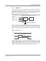
3.1.1
Ignition
Using the ignition pin, the start-up and shut-down of the BL70W can be controlled.
If the ignition pin (IGNITIONCON, KL15) is connected to the power input pin
(POWERCON_IN, KL30) via a switch or a controller, switching on and off of the
BL70W can be controlled without having to disconnect the power supply.
Figure 12. Connection of power pins from PSU
Box PC
Power Input (POWERCON_IN, KL30)
Ignition (IGNITIONCON, KL15)
DC/DC Converter
12V
CPU
GND
(POWERCON_GND, KL31)
When the ignition is turned on, the 12 V supply voltage is also switched on (see
Figure 13, Ignition behavior). When the ignition is turned off, the input voltage is
not switched off at once but can be supplied for a user-defined time (shut-down
delay) so that the operating system of the BL70W can shut down in a controlled
way.
Figure 13. Ignition behavior
Power Input
Definable shut‐
down delay
Ignition
12V
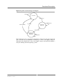
The shut-down delay can be set using a watchdog. If the ignition signal is disabled
and the watchdog is running, it is possible to reset the watchdog timer by software
using the WDOG_EN signal (see Figure 30, SMB 0x4E) to avoid a power
shutdown. If the watchdog is running and the timer is not restarted, the box
computer is forced into power down mode after approximately 5 minutes.
MEN Mikro Elektronik GmbH
20BL70W00 E1 – 2014-12-09
39
Functional Description
Figure 14. Ignition and watchdog state diagram
IGNITION:OFF
Power:OFF
IGNITION:ON
WDOG:TIMEOUT
IGNITION:ON
PS_ON:OFF
Power:ON
WDOG:OFF
IGNITION:OFF
Powerbutton:EVENT
WDOG:ON
Power:ON
WDOG:RESET
The ignition pin (pin 3) can also be permanently connected to the power input pin
(pin 1). In this case the BL70W is starting up as soon as the supply voltage is
connected and switched off as soon as the supply voltage is disconnected without a
delay for shutting down the operating system.
MEN Mikro Elektronik GmbH
20BL70W00 E1 – 2014-12-09
40
Functional Description
3.2
Real-Time Clock
The board includes a real-time clock connected to the processor as a system RTC.
The RTC has an accuracy of approximately 1.7 seconds/day (11 minutes/year) at
25°C.
For data retention during power off the RTC is backed up by a supercapacitor. The
supercapacitor gives an autonomy of up to 72 hours when fully loaded.
The real-time clock device is connected to the CPU via SMBus. Due to its reduced
current consumption, the life time of the battery or supercapacitor can be increased
considerably compared to the RTC integrated in the CPU.
MEN provides a dedicated software driver for the RTC device in order to
set date and time as usual in Windows. For a detailed description of the
functionality of the driver and for downloading the software please refer
to the drivers' documentation on MEN’s website.
3.3
Processor Core
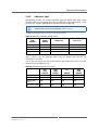
The following processor options are available on the BL70W:
Table 2. Processor core options on BL70W
Processor Type
Core Frequency
Cores/
Threads
Power
Consumption
Cache
AMT
Support
Core i7-3517UE
1.7 GHz
2/4
17 W
4 MB
yes
Core i3-3217UE
1.6 GHz
2/4
17 W
3 MB
no
Celeron 1047UE
1.4 GHz
2/2
17 W
2 MB
no
Celeron 927UE
1.5 GHz
1/1
17 W
1 MB
no
Celeron 827E
1.4 GHz
1/1
17 W
1.5 MB
no
3.3.1
Intel Active Management Technology (AMT)
BL70W box PCs equipped with an Intel Core i7 processor support Intel Active
Management Technology (AMT 8.0). Intel AMT is powered by a separate hardware
engine in Intel chipsets which enables e.g. out-of-band (OOB) diagnostics, remote
control, IDE-Redirect, Serial-over-LAN (SOL), agent presence checking and
network traffic filtering..
MEN provides an application note on how to switch on the AMT
functionality and log onto the CPU board via VNC afterwards. See
MEN’s website.
!
MEN Mikro Elektronik GmbH
20BL70W00 E1 – 2014-12-09
If the supercapacitor and/or the battery is empty, the BL70W loses its
complete AMT settings due to Intel’s security standards.
41
Functional Description
3.3.2
Thermal Considerations
The operating temperature range of the BL70W depends on the system
configuration (CPU, PCIeMiniCards, Ethernet, USB, ...)
The power dissipation of the system also depends on the environmental conditions.
It has a typical power dissipation of 24 W.
The system is designed for a maximum operating temperature of +70°C (+85°C for
10 minutes). The minimum temperature is -40°C for all processors.
As an option, a wider housing with additional cooling fins is available, enabling
permanent operation at +85°C.
MEN Mikro Elektronik GmbH
20BL70W00 E1 – 2014-12-09
42
Functional Description
3.4
Memory and Mass Storage
3.4.1
DRAM System Memory
The standard model of the BL70W is equipped with 4 GB of DDR3 SDRAM. Up to
16 GB are supported.
3.4.2
Boot Flash
The BL70W is equipped with a boot Flash containing its BIOS.
3.4.3
microSD Card Slot
Within its housing, the BL70W provides one microSD card slot. The slot supports
the Secure Digital 2.0 specification (microSDHC) with a storage capacity of 2 up to
16 GB and a data transfer rate of 25 MB/s.
See Chapter 2.2.5 Installing a microSD Card on page 31 for information on how to
install the microSD card.
3.4.4
mSATA Slot
Within its housing, the BL70W provides one mSATA slot.
See Chapter 2.2.6 Installing an mSATA Drive on page 31 for information on how to
install an mSATA disk.
3.4.5
SATA Hard Disk (Optional)
The BL70W offers the possibility to install an additional SATA hard disk in the
housing on a special mounting frame.
Please contact the MEN sales team for further information.
MEN Mikro Elektronik GmbH
20BL70W00 E1 – 2014-12-09
43
Functional Description
3.5
Graphics
3.5.1
DisplayPort Interfaces
Two DisplayPort interface are available at the front panel. The maximum supported
resolution is 2560x1600 at 60 Hz. The interfaces offer AUX channel support and hot
plug detection.
Connector type:
• 20-pin DisplayPort receptacle
Mating connector:
• 20-pin DisplayPort plug
Table 3. Pin assignment of 20-pin DisplayPort connector
1
MEN Mikro Elektronik GmbH
20BL70W00 E1 – 2014-12-09
20
POWER
19
RETURN PWR
18
DP_HOTPLUG
17
DP_AUX-
16
GND
15
DP_AUX+
14
CONFIG2
13
CONFIG1
12
LANE_3-
11
GND
10
LANE_3+
9
LANE_2-
8
GND
7
LANE_2+
6
LANE_1-
5
GND
4
LANE_1+
3
LANE_0-
2
GND
1
LANE_0+
44
Functional Description
Table 4. Signal mnemonics of 20-pin DisplayPort connector
Signal
Direction
Function
GND
-
Ground
DP_AUX-,
DP_AUX+
in/out
Bi-directional half-duplex auxiliary channels for
device management and device control
CONFIG1,
CONFIG2
-
Connected to Ground
DP_HOTPLUG
in
Hot Plug Detect
LANE_[3..0]+,
LANE_[3..0]-
out
Main Link data lanes
POWER
out
Power for connector (3.3 V, 500 mA)
RETURN PWR
-
Return for Power
3.5.2
Other Graphics Interfaces
MEN offers a starter kit including a DisplayPort to DVI adapter.
In addition, many third-party suppliers offer active adapters from DisplayPort to
other graphics interfaces. The maximum resolution depends on the adapter used.
Supported interfaces include:
•
•
•
•
HDMI
Single-link DVI
Dual-link DVI
VGA
MEN Mikro Elektronik GmbH
20BL70W00 E1 – 2014-12-09
45
Functional Description
3.6
USB Interface
The BL70W provides two USB 2.0 interfaces at the front panel via two automotive
USB connectors. The automotive USB connectors are 100% compliant to standard
connectors but offer a more robust connection.
Connector types:
• 4-pin USB Series A receptacle according to Universal Serial Bus Specification
Revision 1.0
• Mating connector:
4-pin USB Series A plug according to Universal Serial Bus Specification Revision 1.0
Table 5. Pin assignment of USB front-panel connectors
1
2
3
4
1
+5V
2
USB_D-
3
USB_D+
4
GND
Table 6. Signal mnemonics of USB front-panel connectors
Signal
Direction
+5V
out
+5 V power supply
GND
-
Digital ground
USB_D+, USB_D- in/out
MEN Mikro Elektronik GmbH
20BL70W00 E1 – 2014-12-09
Function
USB lines, differential pair
46
Functional Description
3.7
Ethernet Interface
The BL70W provides two Gigabit Ethernet ports at the front.
Connector type:
• 8-pin M12 receptacle, female, A-coded 90° (Phoenix Contact 1436974 SACCDSIV-FS-8CON-L90 SCO)
Mating connector:
• 8-pin M12 plug, male, A-coded
MEN offers a starter kit including an M12 to RJ45 adapter for making the Ethernet
interfaces available on standard Ethernet connectors.
For ordering details please consult MEN’s website.
Table 7. Pin assignment of Ethernet front-panel connectors
1000Base-T
7
8
1
2
6
5
1
BI_DC-
2
BI_DD+
3
BI_DD-
4
BI_DA-
TX-
5
BI_DB+
RX+
6
BI_DA+
TX+
7
BI_DC+
-
8
BI_DB-
RX-
3
4
MEN Mikro Elektronik GmbH
20BL70W00 E1 – 2014-12-09
10/100Base-T
47
Functional Description
Table 8. Signal mnemonics of Ethernet front-panel connectors
Signal
Direction
Function
BI_Dx+/- in/out
Differential pairs of data lines for 1000Base-T
RX+/-
in
Differential pair of receive data lines for 10/100Base-T
TX+/-
out
Differential pair of transmit data lines for 10/100Base-T
3.7.1
Ethernet Status LEDs
The BL70W provides a total of four Ethernet status LEDs, two for each Ethernet
channel. They signal the link and activity status (different LED behavior can be
implemented on demand).
Figure 15. Position of Ethernet LEDs at BL70W front (highlighted in red)
DP2
DP1
RS422/485
RS232
ETH1
ETH2
11
12
13
14
X10
X11
X12
Table 9. Ethernet status LEDs
LED
Color
Function
11
Port 1 link
green
on, when connection established
12
Port 1 activity
yellow
on, when Ethernet communication
on Rx or Tx
13
Port 2 link
green
on, when connection established
14
Port 2 activity
yellow
on, when Ethernet communication
on Rx or Tx
MEN Mikro Elektronik GmbH
20BL70W00 E1 – 2014-12-09
Description
48
Functional Description
3.8
HD Audio (Optional)
As an option, the BL70W can be equipped with a high definition audio interface
implemented via the Realtek ALC268 codec and available on a standard 9-pin DSub connector at the front panel.
Table 10. Pin assignment of the HD audio interface
9
6
5
1
9
AUDIO_IN_R
5
AUDIO_SPDIF
8
AUDIO_GND
4
AUDIO_IN_L
7
AUDIO_OUT_R+
3
AUDIO_OUT_R-
6
AUDIO_OUT_L-
2
AUDIO_GND
1
AUDIO_OUT_L+
Table 11. Signal mnemonics of the HD audio interface
Signal
Description
AUDIO_EXT_OUT_L±/R± out
Line out, left and right, differential signal
pairs
AUDIO_EXT_IN_L/R
in
Line in, left and right
AUDIO_EXT_GND
-
Analog ground
AUDIO_EXT_SPDIF
out
S/PDIF output
MEN Mikro Elektronik GmbH
20BL70W00 E1 – 2014-12-09
Direction
49
Functional Description
3.9
Status and User LEDs
In addition to the four Ethernet status LEDs, the BL70W provides two status LEDs
and eight general status LEDs. One of the status LEDs signals whether the onboard
power generated by the BL70W’s on-board DC/DC converter is within valid range,
the other signals the system status (see Chapter 3.9.1 Status LED on page 51 for a
detailed description of the LED’s behavior).
The eight user LEDs can be controlled via an I/O expander on the SMBus. The LED
can be used freely depending on an application’s requirements. See Chapter 4.1
SMBus Overview for information on how to access the LEDs.
Figure 16. Status and user LEDs on the BL70W’s front panel (highlighted in red)
RELAY OUT
PWR
OPT OUT
BIN IN 1
BIN IN 2
3
4
5
6
1
2
X1
X2
DP1
X3
X4
X5
X6
X7
X8
7
8
9
10
X
X9
The following table shows a list of all status and user LEDs with their functionality
or default state.
Table 12. Status and user LEDs on the BL70W
Number
Color
Function
1
Power good
green
on, when internal 12V active
2
Status LED
(diagnostic)
yellow
see Chapter 3.9.1 Status
LED on page 51
3
User LED A
yellow
default: off
4
User LED B
yellow
default: off
5
User LED C
yellow
default: off
6
User LED D
yellow
default: off
7
User LED E
yellow
default: off
8
User LED F
yellow
default: off
9
User LED G
yellow
default: off
10
User LED H
yellow
default: off
MEN Mikro Elektronik GmbH
20BL70W00 E1 – 2014-12-09
Description
50
Functional Description
3.9.1
Status LED
The status LED (LED2) is connected to the system’s board controller.
It has the following behavior:
•
•
•
•
off, if system is in S5 state
blinking at less than 0.5 Hz if system is in S3 state
on, if system is in S0 state and BIOS has sent live sign after power-up
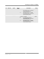
it flashes repeatedly n times according to an error code and pauses for one second until the system is restarted or completely powered-off, if system is in error
condition and error code is n. See the following table for supported error codes.
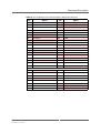
Table 13. Error codes signaled by board management controller via LED flashes
Number
of
Flashes
Description
0
CPUBCI_ERR_NONE
No error
1
CPUBCI_ERR_33V
3.3 V failure
2
CPUBCI_ERR_INP
Input voltage failure
3
CPUBCI_ERR_NO_EXT_PWR_OK
External power supply failure
4
CPUBCI_ERR_CPU_TOO_HOT
CPU temperature too high
5
CPUBCI_ERR_BIOS_TIMEOUT
BIOS startup failure
>5
MEN Mikro Elektronik GmbH
20BL70W00 E1 – 2014-12-09
Error
Internal error
51
Functional Description
3.10
Serial Interfaces
3.10.1
RS232 Interface
The BL70W provides one isolated RS232 interface with a baud rate of up to 115.2
kbaud. The interface (COM1) supports Rx, Tx, RTS and CTS signals.
Connector types
• 9-pin D-Sub plug according to DIN41652/MIL-C-24308, with thread bolt
UNC4-40
• Mating connector:
9-pin D-Sub receptacle according to DIN41652/MIL-C-24308, available for ribbon cable (insulation piercing connection), hand-soldering connection or crimp
connection
Table 14. Pin assignment of 9-pin D-Sub connector for RS232
1
6
9
5
1
-
6
-
2
COM0_RXD
7
COM0_RTS#
3
COM0_TXD
8
COM0_CTS#
4
-
9
-
5
GND
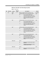
Table 15. Signal mnemonics of RS232 connector
Signal
Function
GND
-
Ground
+5V
out
+5V supply voltage
CTS#
in
Clear to send
RTS#
out
Request to send
RXD
in
Receive data
TXD
out
Transmit data
MEN Mikro Elektronik GmbH
20BL70W00 E1 – 2014-12-09
Direction
52
Functional Description
3.10.2
RS422/485 Interface
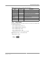
The BL70W provides one isolated RS422/485 full and half duplex interface with a
baud rate of up to 1 Mbaud. It is possible to switch between half and full duplex
mode via application software. The RS422/RS485 interface is switched between
RS422 and RS485 using the RTS signal of the used UART interface (COM2).
Connector types
• 9-pin D-Sub receptacle according to DIN41652/MIL-C-24308, with thread bolt
UNC4-40
• Mating connector:
9-pin D-Sub plug according to DIN41652/MIL-C-24308, available for ribbon
cable (insulation piercing connection), hand-soldering connection or crimp connection
3.10.2.1 Full-Duplex Interface
Table 16. Pin assignment of the 9-pin D-Sub receptacle – full duplex
6
9
1
5
6
I-VCC
1
-
7
-
2
-
8
TX-
3
TX+
9
RX-
4
RX+
5
I-GND
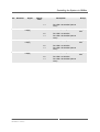
Table 17. Signal mnemonics of RS422/485 interface – full duplex
Signal
Description
I-GND
-
Isolated reference potential
RX+/-
in
Receive data (differential pair)
TX+/-
out
Transmit data (differential pair)
I-VCC
out
Isolated power supply
MEN Mikro Elektronik GmbH
20BL70W00 E1 – 2014-12-09
Direction
53
Functional Description
3.10.2.2 Half-Duplex Interface
Table 18. Pin assignment of the 9-pin D-Sub receptacle – half duplex
6
9
1
5
6
I-VCC
1
-
7
-
2
-
8
RX/TX-
3
RX/TX+
9
-
4
-
5
I-GND
Table 19. Signal mnemonics of RS422/485 interface – half duplex
Signal
Description
I-GND
-
Isolated reference potential
RX+/-
in
Receive data
TX+/-
out
Transmit data
I-VCC
out
Isolated power supply
MEN Mikro Elektronik GmbH
20BL70W00 E1 – 2014-12-09
Direction
54
Functional Description
3.11
Serial Interfaces via SA-Adapter
The BL70W offers the possibility to provide three additional serial interfaces at the
front of the BL70W using MEN standard SA-Adapters. This way, a serial interface
can be used which can be flexibly configured as needed.
Serial interface 3 (COM4) can be used for UART or CAN bus functionality (for
CAN bus functionality a special product version is required), slots 4 (COM3) and 5
(COM0) can be used for UART, IBIS or GPS.
If you use the 08SA15-00 SA-Adapter with SGPIO functionality in slot 5 (X12) you
have to change a setting in the FPGA to switch from UART to SGPIO. See Chapter
5.1 GPIO Controller Instance 1 on page 74.
If you want to use an SA-Adapter at serial interface 3 (X10) you have to activate the
UART in the system’s FPGA. See Chapter 5.1 GPIO Controller Instance 1 on page
74.
Figure 17. Position of serial interfaces on BL70W front
Serial Interface 2
(COM1)
Serial Interface 1
(COM2)
DP1
BIN IN 2
3
4
5
6
X8
DP2
RS422/485
ETH1
RS232
7
8
9
10
ETH2
11
12
13
14
X10
X9
X11
Serial Interface 3
(COM4)
X12
Serial Interface 5
(COM0)
Serial Interface 4
(COM3) See Chapter 2.2.4 Installing SA-Adapters on page 29 for installation instructions.
•
•
MEN Mikro Elektronik GmbH
20BL70W00 E1 – 2014-12-09
See MEN’s website for a list of SA-Adapters which can be used on
the box PC.
Please contact MEN’s sales team for information about possible
configurations and special board versions.
55
Functional Description
3.12
PCI Express Mini Card Interface
The BL70W supports the PCI Express Mini Card standard. Its four PCI Express
Mini Card slots are located within the housing.
Refer to Figure 3, Map of the system – view of the BL70W interior on page 20 for
the exact position of the PCI Express Mini Card slot.
As an option, the BL70W can also be equipped with fourPCI Express Mini Card
slots compatible with half-size modules.
See Chapter 2.2.3 Installing PCI Express Mini Cards on page 27 for information
on how to install the PCI Express Mini Cards in the box PC.
Three of the PCIe MiniCard sockets on the BL70W support both a USB and a PCIe
interface. The fourth socket only supports USB.
The power supply of the PCIe MiniCard can be reset via GPIO. This power reset is
required when switching from one micro-SIM card to another.
See Chapter 4.1 SMBus Overview on page 65 for more information on how to
switch the micro-SIM cards.
Micro-SIM Cards
The BL70W provides eight micro-SIM Card sockets. Two micro-SIM cards are
attached to one PCIe MiniCard socket. Either micro-SIM card A or micro-SIM card
B can be connected to the PCI Express Mini Card. By default the PCI Express Mini
card is connected to micro-SIM card A.
See Chapter 4.1 SMBus Overview on page 65 for more information on how to
switch the micro-SIM cards.
3.12.1
Connection of PCI Express Mini Cards
The PCI Express Mini card is connected using a 52-pin standard PCI Express Mini
Card connector. The following standard signals are supported (signal directions
according to PCI Express Mini Card standard):
MEN Mikro Elektronik GmbH
20BL70W00 E1 – 2014-12-09
56
Functional Description
Table 20. Pin assignment of 52-pin PCI Express Mini Card connector
Pin
Signal
Pin
Signal
51
Reserved
52
+3.3Vaux
49
Reserved
50
GND
47
Reserved
48
+1.5V
45
Reserved
46
LED_WPAN#
43
GND
44
LED_WLAN#
41
+3.3Vaux
42
LED_WWAN#
39
+3.3Vaux
40
GND
37
GND
38
USB_D+
35
GND
36
USB_D-
33
PETp0
34
GND
31
PETn0
32
SMB_DATA
29
GND
30
SMB_CLK
27
GND
28
+1.5V
25
PERp0
26
GND
23
PERn0
24
+3.3Vaux
21
GND
22
PERST#
19
Reserved
20
W_DISABLE#
17
Reserved
18
GND
Mechanical Key
15
GND
16
UIM_VPP
13
REFCLK+
14
UIM_RST
11
REFCLK-
12
UIM_CLK
9
GND
10
UIM_DATA
7
CLKREQ#
8
UIM_PWR
5
Reserved
6
1.5V
3
Reserved
4
GND
1
WAKE#
2
+3.3Vaux
MEN Mikro Elektronik GmbH
20BL70W00 E1 – 2014-12-09
57
Functional Description
Table 21. Signal mnemonics of 52-pin PCI Express Mini Card connector
Signal
Power
SIM card
PCI
Express
Auxiliary
Signals
USB
Communi
cations specific
signals
Direction
Function
GND
-
Ground
+3.3Vaux
out
3.3V source
1.5V
out
1.5V source
UIM_PWR
in
microSIM card power
UIM_DATA
in/out
microSIM card data
UIM_CLK
in
microSIM card clock
UIM_RST
in
microSIM card reset
UIM_VPP
in
not connected
REFCLK-/
REFCLK+
out
PCI Express differential reference
clock
PERn0/PERp0
in
PCI Express receive signals
PETn0/PETp0
out
PCI Express transmit signals
CLKREQ#
in
Clock request
PERST#
out
Reset for the Mini Card
W_DISABLE#
out
Wireless disable
WAKE#
in
Wake signal
SMB_CLK
out
System management bus clock
SMB_DATA
in/out
System management bus data
USB_D-
in/out
USB line
USB_D+
in/out
USB line
LED_WWAN#
in
not connected
LED_WLAN#
in
not connected
LED_WPAN#
in
not connected
Please refer to the PCI Express Mini Card Specification for further details. See
Chapter 7.1 Literature and Web Resources on page 77.
MEN Mikro Elektronik GmbH
20BL70W00 E1 – 2014-12-09
58
Functional Description
3.13
6-Pin Headers
The relay outputs, the binary inputs, the IBIS signals, the odometer input and the
photocoupler signals are available on four 6-pin PCB headers at the BL70W front.
Figure 18. Spring cage terminal blocks
RELAY OUT
OPT OUT
BIN IN 1
BIN IN 2
DP1
3
4
5
6
1
2
X2
X3
X5
X4
X6
X7
X8
DP2
7
8
9
10
X10
X9
Connector type:
• 6-pin header (printed circuit board connector), 3.5 mm, Phoenix Contact DMC
1,5/ 3-G1F-3,5-LR P20THR - 1787027
Mating connector:
• 6-pin plug (printed circuit board connector), e.g. Phoenix Contact DFMC 1,5/ 3ST-3,5-LR - 1790496
Table 22. Pin assignment of relay out connector
5
6
1
5
/ REL2_P
3
REL1_N
1
REL1_P
6
REL2_N
4
REL2_P
2
/ REL1_P
2
Table 23. Pin assignment of opt out connector
5
6
1
5
OPT[2]_P
3
OPT[1]_P
1
Ref. Voltage
6
OPT[2]_N
4
OPT[1]_N
2
Ref. Ground
2
Table 24. Pin assignment of binary I/O connector 1
5
6
1
5
BIN5
3
BIN3
1
BIN1
6
BIN6
4
BIN4
2
BIN2
2
Table 25. Pin assignment of binary I/O connector 2
5
6
MEN Mikro Elektronik GmbH
20BL70W00 E1 – 2014-12-09
1
5
Binary input 7
3
IBIS_RX_P
1
IBIS_TX_P
6
ODO_IN
4
IBIS_RX_N
2
IBIS_TX_N
2
59
Functional Description
Table 26. Signal mnemonics of spring cage terminal block
Signal
Direction
Description
/ REL1/2_P
out
NC (normally closed) contact
REL1/2_P
out
NO (normally open) contact
REL1/2_N
-
Common contact
Reference Ground -
Reference ground for binary inputs
Reference Voltage -
Reference voltage for binary inputs
OPT[1/2]_N/P
out
Photocoupler lines
BIN[1..7]
in
Binary input lines 1 to 7
IBIS_TX_N/P
out
Differential pair of IBIS transmit lines
IBIS_RX_N/P
in
Differential pair of IBIS receive lines
ODO_IN
in
Odometer input line
3.13.1
Relay Outputs
The BL70W supports two relay outputs with two-way contacts for switching with
the following characteristics:
•
•
•
•
•
•
Max. switching current 0..30 V: 2 A
Max. switching current 30..72 V: 0.9 A
Max. switching current 72..154 V: 0.3 A
Max. switching voltage: 154 V
Max. switching frequency: 1 Hz
Minimum life time @ 1A, 30V, 20 cpm: 100.000
Figure 19. Relay switch - 3 lines (default state)
Relay (switch) – 3 lines
REL_N
MEN Mikro Elektronik GmbH
20BL70W00 E1 – 2014-12-09
/REL_P
REL_P
60
Functional Description
3.13.2
Binary Inputs
The BL70W supports seven isolated digital inputs. These inputs work with an input
voltage range from 0 V up to 154 V. This input voltage range is independent of the
power supply input voltage. The BL70W works with a maximum input signal
frequency of 10 Hz.
The input's switching level is 40% (±5%) of the reference voltage. The required
input current for high is > 5mA. The required input current for low is < 1mA.
3.13.3
IBIS
The BL70W provides one isolated IBIS slave interface. The IBIS (Integrated Board
Information System) interface is a serial interface which has been established as a
standard in the transportation sector for the controlling of display modules. It
supports a baud rate of up to 19.2 kbaud.
3.13.4
Photocouplers
The BL70W provides 2 photocouplers used as shutters (see Figure 20,
Photocouplers (shutters) - 2 lines). The shutters are open by default.
• Max switching voltage: 154 V
• Max. current: 120 mA (switching and continuous)
Figure 20. Photocouplers (shutters) - 2 lines
OPT_P
OPT_N
MEN Mikro Elektronik GmbH
20BL70W00 E1 – 2014-12-09
61
Functional Description
3.13.5
Odometer Input
The BL70W provides one isolated odometer input for GNSS. This input counts
odometer pulses of a maximum frequency of 2 kHz. The value of the counter is read
by an IP core (16Z082_IMPULSE) in the FPGA inside the BL70W.
A driver for the IP core is provided on MEN’s website
The BL70W supports input voltage levels of up to 154 V.
Table 27. Odometer switching voltage levels
PD1
(75k)
EN/DIS
PD2
(150k)
EN/DIS
High Level
Low Level
DIS
DIS
4.2 V
1.5 V
DIS
EN
8.4 V
3.0 V
EN
DIS
12.6 V
4.5 V
EN
EN
16.8 V
6V
The odometer default state does not change between power off and power on state.
After a power cycle the odometer input enters its default state and will not
remember its last value.
A reset does not change the state of the odometer input. During and after a reset the
odometer input will hold its state.
Table 28. Odometer default / reset states
PD1
(75k)
EN/DIS
PD2
(150k)
EN/DIS
During Reset
Last value
Last value
Last value
Last value
After Reset
Last value
Last value
Last value
Last value
During power
cycle
DIS
DIS
DIS
EN
After power cycle DIS
DIS
DIS
EN
MEN Mikro Elektronik GmbH
20BL70W00 E1 – 2014-12-09
PU
EN/DIS
Sink
5mA
EN/DIS
62
Functional Description
3.14
GNSS
The BL70W is equipped with the Telit Jupiter SL869 GNSS receiver module with
32 channels. The module supports GPS, Glonass and Galileo.
The GNSS signals are received via a U.FL antenna connector which has to be
connected to an external antenna.
The BL70W itself has no antenna. You need to select and connect an antenna
suitable for your application. The accuracy is mainly dependent on antenna quality.
Please note that MEN does not supply antennas with the BL70W, since the choice
of a suitable antenna depends on your application. The BL70W supports active and
passive antennas. An antenna supply voltage of 5V is provided.
The GNSS receiver converts the data received from the antenna to data packets. The
time mark signal is readable by application software. The data transfer rate is
configurable.
The GNSS's power supply can be reset via GPIO. See Chapter 4.1 SMBus
Overview.
As an option, the BL70W's GNSS supports dead reckoning. The box PC is equipped
with a 3-axis gyrosensor and provides the possibility to connect an odometer to the
GNSS module (see Chapter 4 Controlling the System via SMBus on page 65).
3.14.1
Updating the GNSS Module’s Firmware
It is possible to update the GNSS receiver firmware. For this, the GNSS sensor
voltage has to be switched off and the programming mode be enabled. This can be
done using two control signals which can be accessed via the SMBus and an I/O
expander. See Chapter 4.1 SMBus Overview on page 65 for more information.
Please contact the MEN sales team for further information.
Carry out the following steps to update the GNSS module's firmware;
Remove all power to the module by setting the GPS_PWR_EN bit to '0'.
Enter the programming mode by setting #GPS_FLASH to '0'.
Apply the power by setting the GPS_PWR_EN bit to '1'.
Launch the (Telit) TESEOII X-Loader and set the selections as shown in the
following figure.
MEN Mikro Elektronik GmbH
20BL70W00 E1 – 2014-12-09
63
Functional Description
Figure 21. TESEOII X-Loader settings
Click on the Load button then locate and select the provided software by Telit.
After selecting the correct Output port for the connected receiver (Look under
Device Manager for possible COM connection), click on Send to program the
device.
Upon successful completion of re-flashing, remove main power to the module
for a minimum of 10 seconds by setting the GPS_PWR_EN bit to '0'.
Leave the programming mode by setting the #GPS_FLASH bit to '1'.
Apply the power by setting the GPS_PWR_EN bit to '1'.
Verify that the SL869 has returned to the normal operating state.
See Chapter 7.1.1 GNSS on page 77 for detailed information on the GNSS
module.
MEN Mikro Elektronik GmbH
20BL70W00 E1 – 2014-12-09
64
Controlling the System via SMBus
4
Controlling the System via SMBus
4.1
SMBus Overview
The PCI Express Mini Cards, the microSIM cards, the relays, the photocouplers, the
odometer, the GNSS module and the binary inputs can all be controlled using the
SMBus and five I/O expanders.
MEN offers a driver for accessing the SMBus. See MEN’s website.
Five I/O expanders and a system EEPROM are connected to the SMBus.
Figure 22. SMBus overview
1:IO‐Expander
0x40
: 8x User LED
8x LED
[7:0]
SMB
Board‐to‐
Board‐
Connector
n/a
:4x PCIe :4x PCIe :4x PCIe Minicard
:4x PCIe Minicard
Minicard
Minicard
:4x SIM switch
:4x SIM switch
:4x SIM switch
:4x SIM switch
:4x SIM switch
:4x SIM switch
:4x SIM switch
:2x Relay
2x opto coupler
:Odometer configuration
2:IO‐Expander
0x42
4x Power Enable
4x SIM switch
[3:0]
4x Relay enable
3x Odometer configuration
[3:0]
[7:4]
3:IO‐Expander
0x44
[6:4]
3:IO‐Expander
0x46
2x GPS control
[1:0]
2x DP‐HP enable
[6:5]
7x iso. Inputs
4:IO‐Expander
0x4E
:System EEPROM
0xAC
:GPS module
:2x Display port
:7x isolated inputs
MEN Mikro Elektronik GmbH
20BL70W00 E1 – 2014-12-09
65
Controlling the System via SMBus
4.2
SMBus Register Description
The SMB address is compliant to the Windows nomenclature. This means that the
last bit which is used as the read/write bit is added with the value '0' to the address.
Under Linux a 0 is added at the beginning of the address so that all consecutive
address bits are moved one bit to the right.
Example
Binary address of the I/O-Expander with hard coded offset 0b 0100 and chosen
address bits:
• 0b 0100 (A2)(A1)(A0)(R/W)
With address bits:
• 0b 0100 010 (R/W)
Windows address:
• (R/W) = 0 -> 0b 0100 0100 -> 0x44
Linux address:
• 0b 0010 0010 -> 0x22
Table 29. SMB address space
Address
0xAC
EEPROM, includes system information e.g. serial
number and the date of production.
0x4E
I/O Expander, used to read back the isolated inputs
0x46
I/O Expander, used to control the GNSS module and
ignition status.
0x44
I/O Expander, used to control the odometer interface and
the relay outputs
0x42
I/O Expander, used to power cycle the PCIe Mini Cards
and to switch between the connected SIM cards.
0x40
I/O Expander, used to control the user LEDs at the front
panel.
MEN Mikro Elektronik GmbH
20BL70W00 E1 – 2014-12-09
Function
66
Controlling the System via SMBus
Binary Input Register (0x4E)
Table 30. SMB 0x4E
Bit
Direction
Default
Value
Signal
Description
Group
7
In
BIN_IN[7]
-
Value of the connected isolated input
Isolated
input
6
In
BIN_IN[6]
-
Value of the connected isolated input
Isolated
input
5
In
BIN_IN[5]
-
Value of the connected isolated input
Isolated
input
4
In
BIN_IN[4]
-
Value of the connected isolated input
Isolated
input
3
In
BIN_IN[3]
-
Value of the connected isolated input
Isolated
input
2
In
BIN_IN[2]
-
Value of the connected isolated input
Isolated
input
1
In
BIN_IN[1]
-
Value of the connected isolated input
Isolated
input
0
In
WDOG_
EN
1
Signal to reset the watchdog
System
MEN Mikro Elektronik GmbH
20BL70W00 E1 – 2014-12-09
0=
Setting this bit to '0' generates a
falling edge. The falling edge
results in a reset of the
watchdog.
1=
For every watchdog reset the bit
must be set in sequence '1' -> '0'
to generate a falling edge.
67
Controlling the System via SMBus
GNSS Module Register (0x46)
Table 31. SMB 0x46
Bit
7
Direction
In
Default
value
Signal
IGNITION_ISO -
Description
Bit to read back the ignition status..
0=
Setting this bit to '0' results in
the same behavior as
deactivating the external
ignition signal (power button
event, starting the watchdog
timer)
1=
If the bit is '1' the ignition
signal is active.
Group
System
6
Out
DPB_HP_EN
1
Bit to enable the optional pull up at the
Display Port hot plug signal. No changes
should be made here.
DisplayP
ort
5
Out
DP1_HP_EN
1
Bit to enable the optional pull up at the
Display Port hot plug signal. No changes
should be made here.
DisplayP
ort
4
1
Not used
3
1
Not used
2
1
Not used
1
Controls the operation mode of the GPS
module.
1
0
Out
Out
#GPS_FLASH
GPS_PWR_
EN
MEN Mikro Elektronik GmbH
20BL70W00 E1 – 2014-12-09
1
0=
By setting the bit to '0' the
GPS module is entering the
firmware flash mode.
1=
The default value is '1' and
the GPS module is in normal
operation mode.
Signal to control the GPS module power
supply.
0=
By setting the bit to '0' the
power supply of the GPS
module is switched off.
1=
The default value is '1' and
the GPS module is powered.
GPS
GPS
68
Controlling the System via SMBus
Odometer, Photocoupler, Relay Signals (0x44)
Table 32. SMB 0x44
Bit
Direction
Signal
Default
Value
Description
Group
7
-
-
1
Not used
-
6
Out
ODO_PU_EN
1
Enable signal for the optional pull up of the
odometer interface.
Odometer
5
4
3
2
1
Out
Out
Out
Out
Out
ODO_PD150K 1
_EN
ODO_PD75K
_EN
OPT_EN[2]
OPT_EN[1]
REL_EN[2]
MEN Mikro Elektronik GmbH
20BL70W00 E1 – 2014-12-09
1
1
1
1
0=
By setting the bit to '0' the
corresponding pull up/down
resistor is activated at the
odometer interface.
1=
The default value is '1' and the pull
up/down is not active.
Enable signal for the optional 150k pull
down of the odometer interface.
0=
By setting the bit to '0' the
corresponding pull up/down
resistor is activated at the
odometer interface.
1=
The default value is '1' and the pull
up/down is not active.
Odometer
Enable signal for the optional 75k pull down Odometer
of the odometer interface.
0=
By setting the bit to '0' the
corresponding pull up/down
resistor is activated at the
odometer interface.
1=
The default value is '1' and the pull
up/down is not active.
Enable signal for the second (2) output
photocoupler.
0=
By setting the bit to '0' the
corresponding coupler is closed.
1=
The default value is '1' and the
corresponding coupler is open.
Enable signal for the first (1) output
photocoupler.
0=
By setting the bit to '0' the
corresponding coupler is closed.
1=
The default value is '1' and the
corresponding coupler is open.
Enable signal of the second (2) relay, the
relay is used as a switcher.
Coupler
output
Coupler
output
Relay
output
69
Controlling the System via SMBus
Bit
0
Direction
Out
Signal
REL_EN[1]
MEN Mikro Elektronik GmbH
20BL70W00 E1 – 2014-12-09
Default
Value
1
Description
0=
By setting the bit to '0' the
corresponding relay is closed or
switched (State REL_P).
1=
The default value is '1' and the
corresponding relay is open/ not
switched (State /REL_P).
Enable signal of the first (1) relay, the relay
is used as a switcher.
0=
By setting the bit to '0' the
corresponding relay is closed or
switched (State REL_P).
1=
The default value is '1' and the
corresponding relay is open/ not
switched (State /REL_P).
Group
Relay
output
70
Controlling the System via SMBus
SIM Card, PCIe Mini Card Power Signals (0x42)
Table 33. SMB 0x42
Bit
7
6
5
4
3
2
Direction
Out
Out
Out
Out
Out
Out
Signal
SIMA_
SW
SIMB_
SW
SIMC_
SW
SIMD_
SW
Default
Value
1
1
1
1
MINI_A_ 1
PWR_EN
MINI_B_ 1
PWR_EN
Description
Signal to switch between the primary and
secondary SIM card of the PCIe Mini Card A.
0=
The secondary SIM card is
connected to the PCIe Mini Card
1=
The primary SIM card is connected
to the PCIe Mini Card (default
value).
Signal to switch between the primary and
secondary SIM card of the PCIe Mini Card B.
0=
The secondary SIM card is
connected to the PCIe Mini Card
1=
The primary SIM card is connected
to the PCIe Mini Card (default
value).
Signal to switch between the primary and
secondary SIM card of the PCIe Mini Card C.
0=
The secondary SIM card is
connected to the PCIe Mini Card
1=
The primary SIM card is connected
to the PCIe Mini Card (default
value).
Signal to switch between the primary and
secondary SIM card of the PCIe Mini Card D.
0=
The secondary SIM card is
connected to the PCIe Mini Card
1=
The primary SIM card is connected
to the PCIe Mini Card (default
value).
20BL70W00 E1 – 2014-12-09
PCIe Mini
Card
PCIe Mini
Card
PCIe Mini
Card
PCIe Mini
Card
The bit is used to control the PCIe Mini Card A's PCIe Mini
power.
Card
0=
The power of the PCIe Mini Card is
disabled.
1=
The power of the PCIe Mini Card is
enabled (default value).
The bit is used to control the PCIe Mini Card B's PCIe Mini
power.
Card
0=
MEN Mikro Elektronik GmbH
Group
The power of the PCIe Mini Card is
disabled.
71
Controlling the System via SMBus
Bit
Direction
Signal
Default
Value
Description
1=
1
0
Out
Out
MINI_C_ 1
PWR_EN
Group
The power of the PCIe Mini Card is
enabled (default value).
The bit is used to control the PCIe Mini Card C's PCIe Mini
power.
Card
MINI_D_ 1
PWR_EN
0=
The power of the PCIe Mini Card is
disabled.
1=
The power of the PCIe Mini Card is
enabled (default value).
The bit is used to control the PCIe Mini Card D's PCIe Mini
power.
Card
0=
The power of the PCIe Mini Card is
disabled.
1=
The power of the PCIe Mini Card is
enabled (default value).
User LED Signals (0x40)
Table 34. SMB 0x40
Bit
7
6
5
4
3
Direction
Out
Out
Out
Out
Out
Signal
USR_
LED[10]
USR_
LED[9]
USR_
LED[8]
USR_
LED[7]
USR_
LED[6]
MEN Mikro Elektronik GmbH
20BL70W00 E1 – 2014-12-09
Default
Value
1
1
1
1
1
Description
Enable bit for the corresponding user LED.
0=
The LED is enabled/on.
1=
The LED is disabled/off (default
value).
Enable bit for the corresponding user LED.
0=
The LED is enabled/on.
1=
The LED is disabled/off (default
value).
Enable bit for the corresponding user LED.
0=
The LED is enabled/on.
1=
The LED is disabled/off (default
value).
Enable bit for the corresponding user LED.
0=
The LED is enabled/on.
1=
The LED is disabled/off (default
value).
Enable bit for the corresponding user LED.
Group
USR_
LED
USR_
LED
USR_
LED
USR_
LED
USR_
LED
72
Controlling the System via SMBus
Bit
2
1
0
Direction
Out
Out
Out
Signal
USR_
LED[5]
USR_
LED[4]
USR_
LED[3]
MEN Mikro Elektronik GmbH
20BL70W00 E1 – 2014-12-09
Default
Value
1
1
1
Description
0=
The LED is enabled/on.
1=
The LED is disabled/off (default
value).
Enable bit for the corresponding user LED.
0=
The LED is enabled/on.
1=
The LED is disabled/off (default
value).
Enable bit for the corresponding user LED.
0=
The LED is enabled/on.
1=
The LED is disabled/off (default
value).
Enable bit for the corresponding user LED.
0=
The LED is enabled/on.
1=
The LED is disabled/off (default
value).
Group
USR_
LED
USR_
LED
USR_
LED
73
Using the BL70W with MDIS5 Software
5
Using the BL70W with MDIS5 Software
This chapter gives specific information on how to use the BL70W with the MDIS5
software.
For details about installation and usage of MDIS5 please refer to the
respective MDIS5 user manual. See MEN’s website for detailed
information and documentation of MDIS5.
The UART, CAN and GPIO interfaces of the Box PC are controlled using IP cores
in an FPGA. See the following Figure 35, Chameleon table for a list of the IP cores.
Table 35. Chameleon table
Name
Device Variant Revision Interrupt Group Instance
BAR Offset Size
16Z125_UART
125
0
11
6
0
4
0
220
8
16Z125_UART
125
0
11
4
0
0
0
3F8
8
16Z125_UART
125
0
11
3
0
1
0
2F8
8
16Z125_UART
125
0
11
7
0
2
0
3E8
8
16Z125_UART
125
0
11
5
0
3
0
2E8
8
16Z082_IMPULSE 82
0
2
3F
0
0
1
800
20
16Z034_GPIO
34
0
A
B
0
0
1
E200
20
16Z034_GPIO
34
0
A
B
0
1
1
E240
20
16Z037_GPIO
37
1
1
B
0
0
1
E260
20
16Z126_FLASH
126
0
6
3F
0
0
1
E280
20
16Z029_CAN
29
1
12
B
0
0
1
E400
100
16Z076_QSPI
76
0
7
B
0
0
1
E800
800
16Z029_CAN
29
1
12
B
0
1
1
F000
100
5.1
GPIO Controller Instance 1
The GPIO controller instance 1 is used to switch serial interfaces of the box PCs
from UART to CAN or SGPIO. The functions are switched via multiplexers.
The default device name of the instance 1 of the GPIO controller 16z034- is
"gpio_2" for Linux and "z17_2" for Windows.
Table 36. Functions of GPIO controller instance 1
Bit Position
Input-Function (PSR)
Default Setting
5
mux_if2
-
GPO(5):drive 0
6
mux_if0
-
GPO(6):drive 0
7
mux_if1
-
GPO(7):drive 0
MEN Mikro Elektronik GmbH
20BL70W00 E1 – 2014-12-09
Output-Function
(GPO)
74
Using the BL70W with MDIS5 Software
Interface Multiplexer (mux_if0)
The interface multiplexer 0 is used to change the serial interface 5 (X12) from
UART (default setting) to SGPIO (required if you want to use the SA15 SA-Adapter
in this slot).
Table 37. Interface Multiplexer 0 truth table:
Interface
SA0
Function
mux_if0
UART0
0
SGPIO
1
The interface is switched using the following commands:
For Windows:
z17_io z17_2 -p=6 -s=1 -h
For Linux:
z17_io gpio_2 -p=6 -s=1 -h
Interface Multiplexer (mux_if1)
The interface multiplexer 1 is used to activate serial interface 3 (X10).
Table 38. Interface Multiplexer 1 truth table
Interface
GPIO[7:1]
Function
mux_if1
No functionality
0
Serial Interface 3 (X10) is
active
1
The interface is activated using the following commands:
For Windows:
z17_io z17_2 -p=7 -s=1 -h
For Linux:
z17_io gpio_2 -p=7 -s=1 -h
MEN Mikro Elektronik GmbH
20BL70W00 E1 – 2014-12-09
75
Maintenance
6
Maintenance
6.1
Cleaning the System
The system should be cleaned once a year. Clean the bottom and top plate, remove
dirt and dust from air ventilation holes. Light dirt can be removed with a dry cloth.
Persistent dirt should only be removed with a mild detergent and a soft cloth.
Take care that no liquid gets inside the system.
6.2
Fuse Protection
The DC/DC converter inside the Power Supply Unit is protected by a
fuse. This fuse is not intended to be exchanged by the customer.
Your warranty for the Power Supply Unit will cease if you
exchange the fuse on your own. Please send your unit to MEN for
repair if a fuse blows.
!
•
•
•
•
Current rating: 5 A
Voltage rating: 350 VDC
Type: Time-Lag (T)
MEN part number: 5675-0011
Figure 23. Position of the fuse in the interior of the BL70W (highlighted in red)
13
12
11
10
9
24
MEN Mikro Elektronik GmbH
20BL70W00 E1 – 2014-12-09
76
Appendix
7
Appendix
7.1
Literature and Web Resources
BL70W data sheet with up-to-date information and documentation:
www.men.de/products/09BL70W.htm
7.1.1
GNSS
Jupiter SL869 EVK GNSS module
Jupiter SL869 EVK User Guide
7.1.2
Accelerometer / Magnetometer LSM303DLM
Manufacturer’s product page for LSM303DLM
STMicroelectronics
http://www.st.com/web/en/catalog/sense_power/FM89/SC1449
7.1.3
CAN Bus
CAN in Automation e. V.
www.can-cia.de
7.1.4
DVI
Digital Visual Interface Revision 1.0
www.ddwg.org
7.1.5
Ethernet
•
•
•
MEN Mikro Elektronik GmbH
20BL70W00 E1 – 2014-12-09
ANSI/IEEE 802.3-1996, Information Technology Telecommunications and Information Exchange between Systems
- Local and Metropolitan Area Networks - Specific Requirements Part 3: Carrier Sense Multiple Access with Collision Detection
(CSMA/CD) Access Method and Physical Layer Specifications;
1996; IEEE
www.ieee.org
Charles Spurgeon's Ethernet Web Site
Extensive information about Ethernet (IEEE 802.3) local area
network (LAN) technology.
www.ethermanage.com/ethernet/
InterOperability Laboratory, University of New Hampshire
This page covers general Ethernet technology.
www.iol.unh.edu/services/testing/ethernet/training/
77
Appendix
7.1.6
HD Audio
Intel High Definition Audio:
www.intel.com/design/chipsets/hdaudio.htm
7.1.7
PCI Express Mini Card
PCI Express Mini Card Electromechanical Specification
Revision 1.2; October 26, 2007
PCI Special Interest Group
www.pcisig.com
7.1.8
USB
USB Implementers Forum, Inc.
www.usb.org
7.2
Dimensions of the BL70W Box PC
In the following you can find a drawing of the exact dimensions of the box PC.
MEN Mikro Elektronik GmbH
20BL70W00 E1 – 2014-12-09
78
390 ±2
346 ±2
159
143
119,50
141,99
1
2
3
4
5
24,07
2,50
6
18,50
14
84
7
Y
8
9
10
Z
21
22,65
32,70
36,75
X
37,77
35,8
32,9
17,2
49
120
W
72
11
58
Quantity
Function
Description
Mating connector
1
1
Power
Mini Combicon Plug Grid 3,5mm
Mini Cobicon Jack e.g. Phoenix: 1966101
2
1
Relais output
Dual Mini Combicon Plug
Dual Mini Combicon Jack e.g. Phoenix: 1790496
3
1
Optical output
Dual Mini Combicon Plug
Dual Mini Combicon Jack e.g. Phoenix: 1790496
4
1
Binary input
Dual Mini Combicon Plug
Dual Mini Combicon Jack e.g. Phoenix: 1790496
5
2
USB
USB Type A Jack
USB Type A Plug
6
2
Display
Display Port Jack
Display Port Plug e.g. Molex: 0687830001
7
1
RS422/485
DSub female 9-pin
Dsub male 9-pin
8
1
RS232
DSub male 9-pin
DSub female 9-pin
9
2
Ethernet
M12 Jack 8-pin A-coded
M12 Plug 8-pin e.g. Conec: SAL-12RS8-2/A1
10
1
Ground
M4 Bolt
Cable eye
11
9
Antenna
Pending on function
Pending on function
12
3
SA-Adapter
Pending on function
Pending on function
37,80
99,50
79,50
59,50
Position
44
12
86
100
114
128
142
156
4
206,6 ±1
218,3
+1
0
125
204 ±1
370
X (2 : 1)
W (2 : 1)
Pin1
65,5
Y (2 : 1)
+1
0
Z (2 : 1)
Pin1
Manufacturer number: 09BL70W00
Weight: max. 3,2 kg
Input voltage: 24VDC (nom.)
Operating temperature: -40°C ... +70°C
R3
,60
1.0
Pin1
Pin1
Pin1
sdietz
2014-11-11
Initial version
Rev.: Prepared/ Date: Modification:
Responsible author: S.Dietz
RoHS-compliant (2011/65/EU): yes
Printed versions FOR INFORMATION ONLY.
This is an electronic document. It has been digitally signed. Please see release form.
For this document all rights are reserved.
Scale: 1:2
Tolerance: ---
Material:
----Description:
Surface:
Transparent passivated
(electrically conductiv)
Space allocation drawing
09BL70W00_SAD (1.0)
---
Document No.
09BL70W00_SAD
DIN ISO
13715
DIN
- --- ---
+ --+ ---
A1
Prj.: 1422 Sheet: 1 / 1
MEN_TB_SW_Rev.: 1.0
6,8
214 ±1
M5