1
Embedded Solutions
20AE51-00 E3 – 2011-12-23
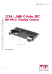
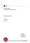
AE51 – Graphics and I/O
Interface for Display
Computers
Configuration example
User Manual
®
AE51 – Graphics and I/O Interface for Display Computers
AE51 – Graphics and I/O Interface for Display Computers
The AE51 is a combined graphics and I/O interface board for MEN's display
computer electronics like the SC24 SBC and possible subsequent models.
Three rugged AirMax VS® connectors transport the various I/O signals from the
SBC board to the AE51, where they are made available on standard connectors like
USB, 9-pin D-Sub (serial I/O and HD audio, both optional), 8-pin M12 (Gigabit
Ethernet), DisplayPort® and SATA. Touch functionality can be realized via the
USB port. Note that the AE51 is just one suggested interface board variant for SBCs
like the SC24 and as such it does not necessarily cover all possible interfaces of the
connected SBC board. For example, only two independent DisplayPort® interfaces
(B and C, with their individual AUX and USB channel respectively) are made
available on standard DP connectors, whereas an SC24 offers two additional
DisplayPort® interfaces (identical to the former two regarding image content).
The AE51 serves as a 2x PCI Express® Mini Card carrier for the connected SBC
board. Two SIM card slots are available. By default, one is used for each of the two
PCI Express® Mini Cards, but the first PCI Express® Mini Card can also switch
between the two SIM cards as an option. The necessary antenna connectors can be
led to a front panel.
As an option, a SATA interface from the SBC board can be made available along
with a 4-pin power connector for the drive, however the AE51 is not designed as a
SATA HDD/SSD carrier board – the drive must be mounted independently.
The board also serves as a 30W 24 VDC nom. (9 to 36 V) class S2 wide-range
power supply for the connected SBC board. If the connected display panels require
more power, an external PSU can be connected via an optional power bypass
connector on the AE51 to supply the necessary 12 VDC voltage for the system.
MEN Mikro Elektronik GmbH
20AE51-00 E3 – 2011-12-23
2
Technical Data
Technical Data
Board-to-board connection
• 3 AirMax VS® connectors
- To SBC board's graphics and I/O connectors P1/P2/P4
I/O
• 2 DisplayPort® interfaces
- DisplayPort® 1 with AUX channel and hot plug detection
- DisplayPort® 2 with USB channel
• HD audio
- HD audio codec (Realtek ALC268)
- Audio stereo in
- Audio stereo out
- SPDIF out
- Via 10-pin onboard connector
• 2 Gigabit Ethernet
- Via M12 connectors
• 1 USB 2.0
- Via Type A connector
• 2 SA-Adapter™ slots for serial I/O
- 1 UART or IBIS, GPS
- 1 UART or CAN bus
• 8 status LEDs
- 4 for Ethernet link and activity status
- 2 for general board status
- 2 for power supply status
2 PCI Express® Mini Card slots
• For functions like WIFI, WIMAX, GSM/GPRS, UMTS
• 2 SIM card slots
• PCI Express® and USB interface
Accelerometer / Magnetometer
• 3 acceleration channels
- 2 independent programmable interrupt generators for free-fall and motion
detection
• 3 magnetic field channels
- ±1.3 to ±8,1 gauss magnetic field full-scale
Miscellaneous
- Gold Cap to buffer real-time clock on connected SBC board
MEN Mikro Elektronik GmbH
20AE51-00 E3 – 2011-12-23
3
Technical Data
Electrical Specifications
• Isolation voltage:
- Ethernet ports: 1,500 VDC
- DC/DC: 1,500 VDC
• Supply voltage:
- 24 VDC nom. (9 to 36 V)
- EN 50155 power interruption class S2
• Power output: 12 VDC nom.
• Power consumption: Up to 30 W
Mechanical Specifications
• Dimensions: approx. 170 mm x 132 mm x 30 mm
• Weight: approx. 100 g
Environmental Specifications
• Temperature range (operation):
- 0..+60°C up to -40..+85°C (screened)
- Fanless operation
• Temperature range (storage): -40..+85°C
• Relative humidity (operation): max. 95% non-condensing
• Relative humidity (storage): max. 95% non-condensing
• Altitude: -300 m to +3,000 m
• Shock: 50 m/s², 30 ms
• Vibration (function): 1 m/s², 5 Hz – 150 Hz
• Vibration (lifetime): 7.9 m/s², 5 Hz – 150 Hz
• Conformal coating on request
MTBF
• tbd. @ 40°C according to IEC/TR 62380 (RDF 2000)
EMC
• Conforming to EN 55022 (radio disturbance), IEC 61000-4-2 (ESD) and IEC
61000-4-4 (burst)
• Prepared for certification according to e1 requirements of the German Federal
Motor Transport Authority
MEN Mikro Elektronik GmbH
20AE51-00 E3 – 2011-12-23
4
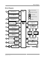
Block Diagram
Block Diagram
G
F
DisplayPort 1
2x USB 2.0
Front connector
G
Graphics connector
IO
I/O connector
B
Onboard connector
DisplayPort 2
F
F
F
Power Supply
Options
B
IO
USB 2.0
F
10/100/1000Base-T
Ethernet
PCI Express®
Mini Card A
10/100/1000Base-T
Ethernet
F
F
F
SIM
Card A
SIM
Card B
USB 2.0
F
F
F
F
SA-Adapter
UART
or CAN
PCI Express®
Mini Card B
F
SA-Adapter
UART
or GPIO
USB 2.0
F
B
HD Audio
MEN Mikro Elektronik GmbH
20AE51-00 E3 – 2011-12-23
SATA
B
5
Configuration Options
Configuration Options
I/O
• DisplayPort® 1 with USB channel instead of AUX channel
• HD audio
- Ribbon cable adapter to 9-pin D-Sub front I/O connector
• Antenna connectors
- For functions like WIFI, WIMAX, GSM/GPRS, UMTS in combination with
PCI Express® Mini Card(s)
- Reverse SMA connector
Mass Storage
• Serial ATA (SATA)
- One port for external hard-disk/solid-state drive
Electrical Specifications
• Input voltage 36 VDC nom. via front connector (alternate internal PSU)
• Input voltage 12 VDC via optional onboard power bypass connector
As the product concept is very flexible, there are many other configuration
possibilities. Please contact our sales team if you do not find your required
function in the options.
For available standard configurations see online data sheet.
MEN Mikro Elektronik GmbH
20AE51-00 E3 – 2011-12-23
6
Product Safety
Product Safety
!
Electrostatic Discharge (ESD)
Computer boards and components contain electrostatic sensitive devices.
Electrostatic discharge (ESD) can damage components. To protect the board and
other components against damage from static electricity, you should follow some
precautions whenever you work on your computer.
• Power down and unplug your computer system when working on the inside.
• Hold components by the edges and try not to touch the IC chips, leads, or circuitry.
• Use a grounded wrist strap before handling computer components.
• Place components on a grounded antistatic pad or on the bag that came with the
component whenever the components are separated from the system.
• Store the board only in its original ESD-protected packaging. Retain the original
packaging in case you need to return the board to MEN for repair.
MEN Mikro Elektronik GmbH
20AE51-00 E3 – 2011-12-23
7
About this Document
About this Document
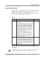
This user manual describes the hardware functions of the board, connection of
peripheral devices and integration into a system. It also provides additional
information for special applications and configurations of the board.
The manual does not include detailed information on individual components (data
sheets etc.). A list of literature is given in the appendix.
History
Issue
Comments
Date
E1
First issue
2011-09-15
E2
2011-11-03
Added cover photo, product weight, DC/DC isolation voltage
Standard model comes without a front panel, some
drawings still depict a possible front panel for clarity
Configuration options: Added SATA, power bypass
connector, USB instead of AUX for DisplayPort 1
HD audio is a standard feature (via onboard connector - D-Sub adapter for front panel optional)
Updated block diagram with the above changes
Clarified position and individual functionality of the
two optional serial interfaces
Added pinout for HD audio onboard connector
Changed order of DisplayPort pinout mnemonics
table
Added product page links for temperature sensor /
EEPROM and accelerometer / magnetometer
Minor changes, cosmetics
E3
Removed pin assignment of board-to-board connector (to be included in manuals for SBC boards),
reworked phrasing regarding DisplayPort connector
pin assignment and USB via AUX option on SC24.
Manual now less focused on a specific SBC board.
Reworked PCI Express Mini Card connector pin
assignment table (signal directions now given from
SBC perspective)
2011-12-09
E4
Added Gold Cap to technical data
2011-12-23
Conventions
!
This sign marks important notes or warnings concerning proper functionality of the
product described in this document. You should read them in any case.
MEN Mikro Elektronik GmbH
20AE51-00 E3 – 2011-12-23
8
About this Document
italics
bold
monospace
hyperlink
Folder, file and function names are printed in italics.
Bold type is used for emphasis.
A monospaced font type is used for hexadecimal numbers, listings, C function
descriptions or wherever appropriate. Hexadecimal numbers are preceded by "0x".
Hyperlinks are printed in blue color.
The globe will show you where hyperlinks lead directly to the Internet, so you can
look for the latest information online.
IRQ#
/IRQ
Signal names followed by "#" or preceded by a slash ("/") indicate that this signal is
either active low or that it becomes active at a falling edge.
in/out
Signal directions in signal mnemonics tables generally refer to the corresponding
board or component, "in" meaning "to the board or component", "out" meaning
"coming from it".
Vertical lines on the outer margin signal technical changes to the previous issue of
the document.
MEN Mikro Elektronik GmbH
20AE51-00 E3 – 2011-12-23
9
About this Document
Legal Information
MEN Mikro Elektronik reserves the right to make changes without further notice to any products herein. MEN makes no
warranty, representation or guarantee regarding the suitability of its products for any particular purpose, nor does MEN assume
any liability arising out of the application or use of any product or circuit, and specifically disclaims any and all liability,
including without limitation consequential or incidental damages.
"Typical" parameters can and do vary in different applications. All operating parameters, including "Typicals" must be
validated for each customer application by customer's technical experts.
MEN does not convey any license under its patent rights nor the rights of others.
Unless agreed otherwise, MEN products are not designed, intended, or authorized for use as components in systems intended
for surgical implant into the body, or other applications intended to support or sustain life, or for any other application in which
the failure of the MEN product could create a situation where personal injury or death may occur. Should Buyer purchase or
use MEN products for any such unintended or unauthorized application, Buyer shall indemnify and hold MEN and its officers,
employees, subsidiaries, affiliates, and distributors harmless against all claims, costs, damages, and expenses, and reasonable
attorney fees arising out of, directly or indirectly, any claim of personal injury or death associated with such unintended or
unauthorized use, even if such claim alleges that MEN was negligent regarding the design or manufacture of the part.
Unless agreed otherwise, the products of MEN Mikro Elektronik are not suited for use in nuclear reactors or for application in
medical appliances used for therapeutical purposes. Application of MEN products in such plants is only possible after the user
has precisely specified the operation environment and after MEN Mikro Elektronik has consequently adapted and released the
product.
ESM™, ESMini™, MDIS™, MDIS4™, MDIS5™, MENMON™, M-Module™, M-Modules™, SA-Adapter™, SAAdapters™, UBox™, USM™ and the MBIOS logo are trademarks of MEN Mikro Elektronik GmbH. PC-MIP® is a
registered trademark of MEN Micro, Inc. and SBS Technologies, Inc. MEN Mikro Elektronik®, ESMexpress®, MIPIOS®
and the MEN logo are registered trademarks of MEN Mikro Elektronik GmbH.
AirMax VS® is a registered trademark of FCI. Altera®, Arria®, Avalon®, Cyclone®, Nios® and Quartus® are registered
trademarks of Altera Corp. InsydeH2O™ is a trademark of Insyde Software Corp. microSD™ is a trademark of SD-3C, LLC.
Microsoft® and Windows® are registered trademarks of Microsoft Corp. Windows® Vista™ is a trademark of Microsoft
Corp. PCI Express® and PCIe® are registered trademarks of PCI-SIG.
All other products or services mentioned in this publication are identified by the trademarks, service marks, or product names
as designated by the companies who market those products. The trademarks and registered trademarks are held by the
companies producing them. Inquiries concerning such trademarks should be made directly to those companies. All other brand
or product names are trademarks or registered trademarks of their respective holders.
Information in this document has been carefully checked and is believed to be accurate as of the date of publication; however,
no responsibility is assumed for inaccuracies. MEN Mikro Elektronik accepts no liability for consequential or incidental
damages arising from the use of its products and reserves the right to make changes on the products herein without notice to
improve reliability, function or design. MEN Mikro Elektronik does not assume any liability arising out of the application or
use of the products described in this document.
Copyright © 2011 MEN Mikro Elektronik GmbH. All rights reserved.
Please recycle
Germany
MEN Mikro Elektronik GmbH
Neuwieder Straße 5-7
90411 Nuremberg
Phone +49-911-99 33 5-0
Fax +49-911-99 33 5-901
E-mail [email protected]
www.men.de
MEN Mikro Elektronik GmbH
20AE51-00 E3 – 2011-12-23
France
MEN Mikro Elektronik SA
18, rue René Cassin
ZA de la Châtelaine
74240 Gaillard
Phone +33 (0) 450-955-312
Fax +33 (0) 450-955-211
E-mail [email protected]
www.men-france.fr
USA
MEN Micro, Inc.
24 North Main Street
Ambler, PA 19002
Phone (215) 542-9575
Fax (215) 542-9577
E-mail [email protected]
www.menmicro.com
10
Contents
Contents
1 Getting Started . . . . . . . . . . . . . . . . . . . . . . . . . . . . . . . . . . . . . . . . . . . . . . . . 13
1.1 Map of the Board. . . . . . . . . . . . . . . . . . . . . . . . . . . . . . . . . . . . . . . . . 13
1.2 Installing the Adapter in a System. . . . . . . . . . . . . . . . . . . . . . . . . . . . 14
2 Interface to CPU Board . . . . . . . . . . . . . . . . . . . . . . . . . . . . . . . . . . . . . . . . . 15
3 Onboard Connectors . . . . . . . . . . . . . . . . . . . . . . . . . . . . . . . . . . . . . . . . . . .
3.1 Power Supply Connector . . . . . . . . . . . . . . . . . . . . . . . . . . . . . . . . . . .
3.2 Power Bypass Connector (optional) . . . . . . . . . . . . . . . . . . . . . . . . . .
3.3 Mass Storage . . . . . . . . . . . . . . . . . . . . . . . . . . . . . . . . . . . . . . . . . . . .
3.3.1
Serial ATA (SATA) (optional). . . . . . . . . . . . . . . . . . . . . . . .
3.4 DisplayPort Interfaces . . . . . . . . . . . . . . . . . . . . . . . . . . . . . . . . . . . . .
3.5 USB Interface . . . . . . . . . . . . . . . . . . . . . . . . . . . . . . . . . . . . . . . . . . .
3.6 Ethernet Interface . . . . . . . . . . . . . . . . . . . . . . . . . . . . . . . . . . . . . . . .
3.6.1
Ethernet Status LEDs . . . . . . . . . . . . . . . . . . . . . . . . . . . . . .
3.7 General Status LEDs . . . . . . . . . . . . . . . . . . . . . . . . . . . . . . . . . . . . . .
3.8 HD Audio . . . . . . . . . . . . . . . . . . . . . . . . . . . . . . . . . . . . . . . . . . . . . .
3.9 Serial Interfaces via SA-Adapter (optional) . . . . . . . . . . . . . . . . . . . .
3.10 PCI Express Mini Card Interface. . . . . . . . . . . . . . . . . . . . . . . . . . . . .
3.10.1 SIM Card Slots . . . . . . . . . . . . . . . . . . . . . . . . . . . . . . . . . . .
16
16
16
17
17
18
19
20
20
21
22
22
23
26
4 Organization of the Board . . . . . . . . . . . . . . . . . . . . . . . . . . . . . . . . . . . . . . . 27
4.1 SMBus Devices . . . . . . . . . . . . . . . . . . . . . . . . . . . . . . . . . . . . . . . . . . 27
5 Appendix . . . . . . . . . . . . . . . . . . . . . . . . . . . . . . . . . . . . . . . . . . . . . . . . . . . . .
5.1 Literature and Web Resources . . . . . . . . . . . . . . . . . . . . . . . . . . . . . . .
5.1.1
PCI Express Mini Card . . . . . . . . . . . . . . . . . . . . . . . . . . . . .
5.1.2
Accelerometer / Magnetometer STTS424E02 . . . . . . . . . . .
5.1.3
Temperature Sensor / EEPROM LSM303DLH . . . . . . . . . .
5.2 Finding out the Product’s Article Number,
Revision and Serial Number . . . . . . . . . . . . . . . . . . . . . . . . . . . . . . . .
MEN Mikro Elektronik GmbH
20AE51-00 E3 – 2011-12-23
28
28
28
28
28
28
11
Figures
Figure 1. Map of the board – top view. . . . . . . . . . . . . . . . . . . . . . . . . . . . . . . . .
Figure 2. Map of the board – front connectors
shown behind possible front panel . . . . . . . . . . . . . . . . . . . . . . . . . . . .
Figure 3. Connecting an AE51 and an SBC board
via the AirMax VS connectors . . . . . . . . . . . . . . . . . . . . . . . . . . . . . . .
Figure 4. General status LEDs on a possible front panel (shown partially) . . . .
Figure 5. SIM card switching option . . . . . . . . . . . . . . . . . . . . . . . . . . . . . . . . . .
Figure 6. Labels giving the product’s article number,
revision and serial number . . . . . . . . . . . . . . . . . . . . . . . . . . . . . . . . . .
13
14
14
21
26
28
Tables
Table 1.
Table 2.
Table 3.
Table 4.
Table 5.
Table 6.
Table 7.
Table 8.
Table 9.
Table 10.
Table 11.
Table 12.
Table 13.
Table 14.
Table 15.
Table 16.
Table 17.
Table 18.
MEN Mikro Elektronik GmbH
20AE51-00 E3 – 2011-12-23
Pin assignment of PSU connector . . . . . . . . . . . . . . . . . . . . . . . . . . . .
Pin assignment of optional power bypass connector . . . . . . . . . . . . . .
Pin assignment of optional SATA connector . . . . . . . . . . . . . . . . . . . .
Pin assignment of optional HDD/SSD power supply connector . . . . .
Pin assignment of 20-pin DisplayPort connector . . . . . . . . . . . . . . . . .
Signal mnemonics of 20-pin DisplayPort connector . . . . . . . . . . . . . .
Pin assignment of USB front-panel connectors . . . . . . . . . . . . . . . . . .
Pin assignment of Ethernet front-panel connectors . . . . . . . . . . . . . . .
Signal mnemonics of Ethernet front-panel connectors. . . . . . . . . . . . .
Ethernet status LED . . . . . . . . . . . . . . . . . . . . . . . . . . . . . . . . . . . . . . .
General status LEDs (as depicted above) . . . . . . . . . . . . . . . . . . . . . . .
Pin assignment of the HD audio onboard connector . . . . . . . . . . . . . .
Pin assignment of the optional HD audio D-Sub front connector . . . .
Signal mnemonics of the HD audio interface. . . . . . . . . . . . . . . . . . . .
Pin assignment of 52-pin PCI Express Mini Card connector. . . . . . . .
Signal mnemonics of 52-pin PCI Express Mini Card connector . . . . .
SIM card switching option . . . . . . . . . . . . . . . . . . . . . . . . . . . . . . . . . .
SMBus devices . . . . . . . . . . . . . . . . . . . . . . . . . . . . . . . . . . . . . . . . . . .
16
16
17
17
18
18
19
20
20
20
21
22
22
22
23
25
26
27
12
Getting Started
1
Getting Started
This chapter gives an overview of the board and some hints for first installation in a
system.
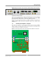
1.1
Map of the Board
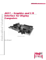
Figure 1. Map of the board – top view
AirMax VS
board-to-board
connector
AirMax VS
board-to-board
connectors
Power bypass
connector
(optional)
HD Audio
Power Input
2x DisplayPort
MEN Mikro Elektronik GmbH
20AE51-00 E3 – 2011-12-23
PCI Express
Mini Card B
PCI Express
Mini Card A
J1
J4 J2
SATA
port +
power
(optional)
SIM
Card A
SIM
Card B
Serial I/O 2
UART, IBIS
or GPS
USB
HD Audio to
optional front
connector
Serial I/O 1
UART or
CAN bus
2x Gigabit Ethernet
13
Getting Started
Figure 2. Map of the board – front connectors shown behind possible front panel
X1
X2
ETH1
1
X3
ETH2
2
3
4
USB
DP1
X4
DP2
AUDIO
5
7
6
8
PWR
X5
X6
All optional connectors shown.
Top level, left to right: PCI Express Mini Card B SMA antenna connectors, Ethernet
port 1 status LEDs, Ethernet port 1, Ethernet port 2, Ethernet port 2 status LEDs,
USB, DisplayPort 1, DisplayPort 2, general status LEDs, power input
Bottom level, left to right: Serial interface 1 (UART or CAN bus), serial interface 2
(UART or IBIS or GPS), HD audio, PCI Express Mini Card A SMA antenna
connectors.
1.2
Installing the Adapter in a System
The AE51 was designed as a joint graphics and I/O connector board for MEN’s
display computer electronics like the SC24. The connection to the SBC board is
realized via two pairs of AirMax VS connectors.
Figure 3. Connecting an AE51 and an SBC board via the AirMax VS connectors
SC24
P1
P4 P2
J1
J4 J2
AE51
MEN Mikro Elektronik GmbH
20AE51-00 E3 – 2011-12-23
14
Interface to CPU Board
2
Interface to CPU Board
The AE51 is connected to the SBC board via three AirMax VS connectors, serving
as a joint I/O and graphics interface board.
Connector type:
• 72-pin AirMax VS press-fit receptacle, 6 rows, right-angle (FCI 10114633-101LF)
Mating connector:
• 72-pin AirMax VS press-fit 2 wall signal header, 6 rows, right angle header (FCI
10052824-101LF)
The pin assignment matches the compatible SBC boards, e.g., the SC24, and is not
repeated here. Please refer to the SBC board’s manual for a complete list of signals.
MEN Mikro Elektronik GmbH
20AE51-00 E3 – 2011-12-23
15
Onboard Connectors
3
Onboard Connectors
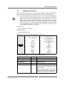
3.1
Power Supply Connector
The AE51 is supplied with 24 VDC nom. (9 to 36 V) via a 3-pin COMBICON
connector. An input voltage of 36 VDC nom. can be realized as an option.
Connector type:
• 3-pin COMBICON receptacle (Phoenix Contact 1843800 MC 1,5/ 3-GF-3,5)
Mating connector:
• 3-pin COMBICON plug, e.g., Phoenix Contact 1863314 MCVR 1,5/ 3-STF-3,5
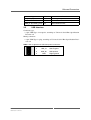
Table 1. Pin assignment of PSU connector
1
1
3
2
3
3.2
POWERCON_IN
Power input
POWERCON_GND Power input ground
IGNITIONCON
Ignition
Power Bypass Connector (optional)
If the power consumption of the system should exceed the 30 W limit of the AE51’s
integrated power supply, e.g., when the system is also used to power a large display
panel, the board’s internal DC/DC converter can be bypassed. For this purpose, the
board can be equipped with the optional power bypass connector to enable the
connection of a more powerful external PSU, supplying the connected SBC board
with the necessary input voltage of 12 VDC.
Connector type:
• 4-pin COMBICON receptacle (Phoenix Contact 1755752 MSTBVA 2,5/ 4-G5,08)
Mating connector:
• 4-pin COMBICON plug, e.g., Phoenix Contact 1786420 IC 2,5/ 4-G-5,08
Table 2. Pin assignment of optional power bypass connector
MEN Mikro Elektronik GmbH
20AE51-00 E3 – 2011-12-23
1
VCC_FLYBACK
Power to additional DC/DC
converter output
2
IGND
Isolated power input ground
3
12V_FLYBACK_OUT
4
GND
12V from external DC/DC converter
GND
16
Onboard Connectors
3.3
Mass Storage
3.3.1
Serial ATA (SATA) (optional)
As an option, the AE51 can provide one serial ATA (SATA) interface controlled by
the connected CPU board. It is available via a standard 7-pin SATA connector. You
can connect a hard-disk or solid state drive. Please note that the AE51 is not
designed as a carrier board for such drives - any drives have to be installed
externally. Power for the drive is supplied via a 2.5mm 4-pin header. Please refer to
Figure 1, Map of the board – top view on page 13 for the connectors’ exact
positions.
The SATA interfaces support transfer rates up to 300 MB/s.
Connector type:
• 7- pin SATA receptacle, 1.27mm pitch
Mating connector:
• 7- pin SATA plug, 1.27mm pitch
Table 3. Pin assignment of optional SATA connector
S1
S1
GND
Digital ground
S2
SATA_TX+
SATA transmit positive
S3
SATA_TX-
SATA transmit negative
S4
GND
S5
SATA_RX-
SATA receive positive
S6
SATA_RX+
SATA receive negative
S7
GND
Digital ground
Digital ground
Connector type:
• 4-pin header for IDE drive power supply (2.5 mm)
Mating connector:
• 4-pin IDE drive power plug (2.5 mm)
Table 4. Pin assignment of optional HDD/SSD power supply connector
MEN Mikro Elektronik GmbH
20AE51-00 E3 – 2011-12-23
S1
+12V
+12V power supply
S2
GND12V
Digital ground
S3
GND5V
Digital ground
S4
+5V
+5V power supply
17
Onboard Connectors
3.4
DisplayPort Interfaces
Two of the DisplayPort interfaces available on the SBC board (DisplayPort B on the
DP1 connector and DisplayPort C on DP2) can be accessed at the front panel.
!
Note: Only DisplayPort B (on the DP1 connector) is a fully featured DisplayPort
interface and offers AUX channel support and hot plug detection. With the
DisplayPort C interface (on the DP2 connector), the AUX lines are used for a
USB connection. This makes it impossible for the SBC board to exchange
device management and control data with the display panel connected to this
interface, but in turn it enables features like an USB-driven touch interface
via the DisplayPort connector. USB instead of AUX can also be made available on the DP1 connector as an option.
Connector type:
• 20-pin DisplayPort receptacle
Mating connector:
• 20-pin DisplayPort plug
Table 5. Pin assignment of 20-pin DisplayPort connector
20
POWER
19
RETURN PWR
18
DPx_HOTPLUG
17
DPx_AUX(option: DPx_USB_n)
16
GND
15
DPx_AUX+
(option: DPx_USB_p)
14
CONFIG2
13
CONFIG1
12
LANE_3-
11
GND
10
LANE_3+
9
LANE_2-
8
GND
7
LANE_2+
6
LANE_1-
5
GND
4
LANE_1+
3
LANE_0-
2
GND
1
LANE_0+
Table 6. Signal mnemonics of 20-pin DisplayPort connector
Signal
Direction
Function
GND
-
Ground
POWER
out
Power for connector (3.3 V, 500 mA)
RETURN PWR
-
Return for Power
DPx_HOTPLUG
in
Hot Plug Detect
DPx_AUX-, DPx_AUX+
in/out
Bi-directional half-duplex auxiliary
channels for device management and
device control
Note: As an option, these lines can be
used for a USB interface, as realized for
DisplayPort C on the SC24 SBC board.
MEN Mikro Elektronik GmbH
20AE51-00 E3 – 2011-12-23
18
Onboard Connectors
Signal
Direction
Function
DPx_USB_n/p
in/out
USB negative/positive
CONFIG1, CONFIG2
-
Connected to Ground
LANE_[3..0]+,LANE_[3..0]-
out
Main Link data lanes
3.5
USB Interface
Connector type:
• 4-pin USB Type A receptacle according to Universal Serial Bus Specification
Revision 1.0
Mating connector:
• 4-pin USB Type A plug according to Universal Serial Bus Specification Revision 1.0
Table 7. Pin assignment of USB front-panel connectors
1
2
3
4
MEN Mikro Elektronik GmbH
20AE51-00 E3 – 2011-12-23
1
+5V
+5 V power supply
2
USB_D-
USB negative
3
USB_D+
USB positive
4
GND
Digital ground
19
Onboard Connectors
3.6
Ethernet Interface
For detailed information regarding the Ethernet controllers, MAC address etc please
consult the SBC board manual. This manual only deals with the physical Ethernet
connectors on the AE51.
Connector type:
• 8-pin M12 receptacle, female, A-coded 90° (Phoenix Contact 1436974 SACCDSIV-FS-8CON-L90 SCO)
Mating connector:
• 8-pin M12 plug, male, A-coded
Table 8. Pin assignment of Ethernet front-panel connectors
1000Base-T
7
8
1
2
6
10/100Base-T
1
BI_DC-
2
BI_DD+
3
BI_DD-
4
BI_DA-
TX-
5
BI_DB+
RX+
6
BI_DA+
TX+
7
BI_DC+
-
8
BI_DB-
RX-
3
5
4
Table 9. Signal mnemonics of Ethernet front-panel connectors
Signal
Direction
Function
BI_Dx+/-
in/out
Differential pairs of data lines for 1000Base-T
RX+/-
in
Differential pair of receive data lines for 10/
100Base-T
TX+/-
out
Differential pair of transmit data lines for 10/
100Base-T
3.6.1
Ethernet Status LEDs
The AE51 provides a total of four Ethernet status LEDs, two for each Ethernet
channel. They signal the link and activity status (different LED behavior can be
realized on demand).
Table 10. Ethernet status LED
LED
LED
Description
1
Port 1 activity
3
Port 2 activity
2
Port 1 link
4
Port 2 link
MEN Mikro Elektronik GmbH
20AE51-00 E3 – 2011-12-23
Description
20
Onboard Connectors
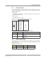
3.7
General Status LEDs
In addition to the four Ethernet status LEDs, the AE51 provides four general status
LEDs. Two of them signal whether input power is applied and whether the output
power to the SBC board as generated by the AE51’s onboard DC/DC converter is
within valid range.
The status LED is connected to the system’s board management controller. Please
refer to the manual for the connected SBC board for information on its behaviour.
The user LED A is connected to an SGPIO line and can be used freely depending on
an application’s requirements.
Figure 4. General status LEDs on a possible front panel (shown partially)
DP2
AUDIO
5
7
6
8
PWR
X5
X6
Table 11. General status LEDs (as depicted above)
LED
LED
Description
5
Output power 12V OK
7
Status
6
Input power applied
8
User LED A
MEN Mikro Elektronik GmbH
20AE51-00 E3 – 2011-12-23
Description
21
Onboard Connectors
3.8
HD Audio
The AE51 supports a high definition audio interface implemented via the Realtek
ALC268 codec. It is available on a 10-pin onboard connector and can be led to a
standard 9-pin D-Sub front connector via an optional ribbon cable adapter.
Connector types:
10-pin low profile header with lock, 2.54 mm pitch, for ribbon-cable connection
Mating connector:
10-pin IDC receptacles, e.g., Elco Series 8290 IDC socket
Table 12. Pin assignment of the HD audio onboard connector
1
2
9
10
1
AUDIO_OUT_L+
2
AUDIO_GND
3
AUDIO_OUT_R-
4
AUDIO_IN_L
5
AUDIO_SPDIF
6
AUDIO_OUT_L-
7
AUDIO_OUT_R+
8
AUDIO_GND
9
AUDIO_IN_R
10
not connected
Table 13. Pin assignment of the optional HD audio D-Sub front connector
5
9
6
1
9
AUDIO_IN_R
5
AUDIO_SPDIF
8
AUDIO_GND
4
AUDIO_IN_L
7
AUDIO_OUT_R+
3
AUDIO_OUT_R-
6
AUDIO_OUT_L-
2
AUDIO_GND
1
AUDIO_OUT_L+
Table 14. Signal mnemonics of the HD audio interface
Signal
Direction
Description
AUDIO_OUT_L±/R± out
Line out, left and right, differential signal pairs
AUDIO_IN_L/R
in
Line in, left and right
AUDIO_GND
-
Analog ground
AUDIO_SPDIF
out
S/PDIF output
3.9
Serial Interfaces via SA-Adapter (optional)
As an option, the board offers the possibility to provide two serial interfaces at the
connector PCB using a MEN standard SA-Adapter. This way, a serial interface can
be used which can be flexibly configured as needed. SA-Adapter slot 1 (available at
the X3 front connector) can be used for UART or CAN bus while slot 2 (X4) can be
used for UART, IBIS or GPS functionality. Please consult the respective SAAdapter user manual for installation instructions.
See MEN’s website for a list of SA-Adapters which can be used on the AE51.
Please contact MEN’s sales team for information about possible configurations
and special board versions.
MEN Mikro Elektronik GmbH
20AE51-00 E3 – 2011-12-23
22
Onboard Connectors
3.10
PCI Express Mini Card Interface
The AE51 supports the PCI Express Mini Card standard. As an option, it can also be
equipped with PCI Express Mini Card slots compatible with half-size modules.
PCI Express Mini Cards are small form factor PCI Express cards. The main
differences between an ExpressCard and a PCI Express Mini Card is a smaller form
factor optimized for mobile computing platforms and a card-system Interconnection
optimized for communication applications. PCI Express Mini Cards also use
smaller connectors than standard ExpressCards.
The cards use either a single PCI Express lane (x1) or a USB connection; the AE51
supports both. It is equipped with two 52-pin standard PCI Express Mini Card
connectors. The following standard signals are supported (signal directions
according to PCI Express Mini Card standard):
Table 15. Pin assignment of 52-pin PCI Express Mini Card connector
Pin
Signal
Pin
Signal
51
Reserved
52
+3.3Vaux
49
Reserved
50
GND
47
Reserved
48
+1.5V
45
Reserved
46
LED_WPAN#
43
GND
44
LED_WLAN#
41
+3.3Vaux
42
LED_WWAN#
39
+3.3Vaux
40
GND
37
GND
38
USB_D+
35
GND
36
USB_D-
33
PETp0
34
GND
31
PETn0
32
SMB_DATA
29
GND
30
SMB_CLK
27
GND
28
+1.5V
25
PERp0
26
GND
23
PERn0
24
+3.3Vaux
21
GND
22
PERST#
19
Reserved
20
W_DISABLE#
17
Reserved
18
GND
Mechanical Key
15
GND
16
UIM_VPP
13
REFCLK+
14
UIM_RST
11
REFCLK-
12
UIM_CLK
9
GND
10
UIM_DATA
7
CLKREQ#
8
UIM_PWR
5
Reserved
6
1.5V
MEN Mikro Elektronik GmbH
20AE51-00 E3 – 2011-12-23
23
Onboard Connectors
Pin
Pin
Signal
3
Reserved
4
GND
1
WAKE#
2
+3.3Vaux
MEN Mikro Elektronik GmbH
20AE51-00 E3 – 2011-12-23
Signal
24
Onboard Connectors
Table 16. Signal mnemonics of 52-pin PCI Express Mini Card connector
Signal
Power
SIM card
PCI
Express
Auxiliary
Signals
USB
Direction
Function
GND
-
Ground
+3.3Vaux
out
3.3V source
1.5V
out
1.5V source
UIM_PWR
in
SIM card power
UIM_DATA
in/out
SIM card data
UIM_CLK
in
SIM card clock
UIM_RST
in
SIM card reset
UIM_VPP
in
not connected
REFCLK-/REFCLK+
out
PCI Express differential reference
clock
PERn0/PERp0
in
PCI Express receive signals
PETn0/PETp0
out
PCI Express transmit signals
CLKREQ#
in
Clock request
PERST#
out
Reset for the Mini Card
W_DISABLE#
out
Wireless disable
WAKE#
in
Wake signal
SMB_CLK
out
System management bus clock
SMB_DATA
in/out
System management bus data
USB_D-
in/out
USB line
USB_D+
in/out
USB line
in
not connected
in
not connected
in
not connected
Communi- LED_WWAN#
cations LED_WLAN#
specific
LED_WPAN#
signals
Please refer to the PCI Express Mini Card Specification for further details. See
Chapter 5.1 Literature and Web Resources on page 28.
MEN Mikro Elektronik GmbH
20AE51-00 E3 – 2011-12-23
25
Onboard Connectors
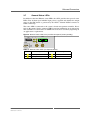
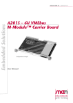
3.10.1
SIM Card Slots
The AE51 offers two SIM card slots for the two PCI Express Mini Card slots. The
default setting has Mini Card A connected to SIM card A and Mini Card B to SIM
card B. However, both SIM card slots can be connected to PCI Express Mini Card A
if needed. The necessary switching is performed by software via the SIMA_SW and
SIMB_SW lines.
Figure 5. SIM card switching option
SIM
Card B
SIM Card A
S1
PCI Express Mini Card A
S2
PCI Express Mini Card B
Table 17. SIM card switching option
SIMA_SW SIMB_SW
PCI Express Mini Card B
connected to
0
0
SIM card A
SIM card B
0
1
SIM card A
-
1
0
-
SIM card B
1
1
SIM card B
-
MEN Mikro Elektronik GmbH
20AE51-00 E3 – 2011-12-23
PCI Express Mini Card A
connected to
26
Organization of the Board
4
Organization of the Board
4.1
SMBus Devices
The AE51 adds three additional SMBus devices to the system it is connected to.
Table 18. SMBus devices
I2C Bus
Function
0
0x30 (write)
0x31 (read)
LSM303DLH accelerometer
0
0x3C (write)
0x3D (read)
LSM303DLH magnetometer
1
0xAC
STTS424E02 temperature sensor
and production data EEPROM
MEN Mikro Elektronik GmbH
20AE51-00 E3 – 2011-12-23
Address
27
Appendix
5
Appendix
5.1
Literature and Web Resources
• AE51 data sheet with up-to-date information and documentation:
www.men.de/products/08AE51-.html
5.1.1
PCI Express Mini Card
• PCI Express Mini Card Electromechanical Specification
Revision 1.2; October 26, 2007
PCI Special Interest Group
www.pcisig.com
5.1.2
Accelerometer / Magnetometer STTS424E02
• Manufacturer’s product page for STTS424E02 – Memory module temperature
sensor with a 2 Kb SPD EEPROM
STMicroelectronics
http://www.st.com/internet/analog/product/250145.jsp
5.1.3
Temperature Sensor / EEPROM LSM303DLH
• Manufacturer’s product page for LSM303DLH
STMicroelectronics
http://www.st.com/internet/analog/product/147880.jsp
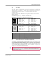
5.2
Finding out the Product’s Article Number, Revision and
Serial Number
MEN user documentation may describe several different models and/or design
revisions of the AE51. You can find information on the article number, the design
revision and the serial number on two labels attached to the board.
• Article number: Gives the product’s family and model. This is also MEN’s
ordering number. To be complete it must have 9 characters.
• Revision number: Gives the design revision of the product.
• Serial number: Unique identification assigned during production.
If you need support, you should communicate these numbers to MEN.
Figure 6. Labels giving the product’s article number, revision and serial number
Complete article number
08AE51-00
00.00.00
Revision number
Serial number
MEN Mikro Elektronik GmbH
20AE51-00 E3 – 2011-12-23
28