1
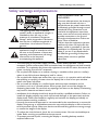
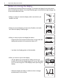
PL550
Digital Signage
User Manual
Disclaimer
BenQ Corporation makes no representations or warranties, either expressed or
implied, with respect to the contents of this document. BenQ Corporation reserves the
right to revise this publication and to make changes from time to time in the contents
thereof without obligation to notify any person of such revision or changes.
Copyright
Copyright 2015 BenQ Corporation. All rights reserved. No part of this publication may
be reproduced, transmitted, transcribed, stored in a retrieval system or translated into
any language or computer language, in any form or by any means, electronic, mechanical,
magnetic, optical, chemical, manual or otherwise, without the prior written permission
of BenQ Corporation.
Table of Contents
Table of Contents
Safety warnings and precautions ....................................... 1
Important safety instructions............................................. 2
Notes on the LCD panel of this display......................................2
Notes on condensation...................................................................3
Battery safety notice ........................................................................3
Safety notice for remote control..................................................3
Notes on moving the display .........................................................4
BenQ ecoFACTS ..............................................................................5
Package contents .................................................................. 6
Optional accessories........................................................................6
Setting up the display ........................................................... 7
Mounting the display........................................................................7
Parts of the display and their functions ........................... 9
Rear panel .........................................................................................9
Input/output terminals...................................................................11
Remote control...............................................................................13
Using the remote control .............................................................14
Connection ..........................................................................15
Connecting audio/video signals ...................................................15
Connecting power..........................................................................21
Basic operations..................................................................22
Turning the display on or off .......................................................22
Locking/unlocking the controls ...................................................22
Switching input signals ...................................................................22
Adjusting audio volume level .......................................................22
Network connection .........................................................23
Connecting to a LAN ....................................................................23
Controlling the display over LAN ..............................................23
The OSD (On-Screen Display) menu ............................27
i
ii
Table of Contents
OSD menu overview .................................................................... 27
Operations in the OSD menu..................................................... 28
Picture menu .................................................................................. 29
Sound menu..................................................................................... 30
Screen menu ................................................................................... 31
Setting menu ................................................................................... 35
Multimedia OSD operation.............................................. 38
Multimedia buttons on the remote control ............................ 38
Viewing files..................................................................................... 39
Making connections....................................................................... 47
Composing a display wall ............................................................. 51
Menu system ................................................................................... 52
Product information........................................................... 55
Specifications................................................................................... 55
Dimensions...................................................................................... 57
Supported input signal resolution .............................................. 58
Supported PAP input signal combination.................................. 60
Troubleshooting .................................................................. 61
Safety warnings and precautions
1
Safety warnings and precautions
The lightning flash with arrowhead
symbol, within an equilateral triangle, is
intended to alert the user to the
presence of uninsulated "dangerous
voltage" within the product's enclosure
that may be of sufficient magnitude to
constitute a risk of electric shock to
persons.
The exclamation point within an
equilateral triangle is intended to alert
the user to the presence of important
operating and maintenance (servicing)
instructions in the literature
accompanying the appliance.
THIS EQUIPMENT MUST BE
GROUNDED
To ensure safe operation, the three-pin
plug must be inserted only into a
standard three-pin power outlet which
is effectively grounded through normal
household wiring. Extension cords
used with the equipment must have
three cores and be correctly wired to
provide connection to the ground.
Wrongly wired extension cords are a
major cause of fatalities.
The fact that the equipment operates
satisfactorily does not imply that the
power outlet is grounded or that the
installation is completely safe. For your
safety, if you are in any doubt about
the effective grounding of the power
outlet, please consult a qualified
electrician.
• The mains plug of the power supply cord shall remain readily operable. The AC
receptacle (mains socket outlet) shall be installed near the equipment and shall be easily
accessible. To completely disconnect this equipment from the AC mains, disconnect the
power cord plug from the AC receptacle.
• Do not place this display on an uneven, sloping or unstable surface (such as a trolley)
where it may fall and cause damage to itself or others.
• Do not place this display near water, like a spa or pool, or in a position which will allow
the splashing or spraying of water onto the display, like in front of an open window
where rain water may enter.
• Do not install this display in a confined space without proper ventilation and air
circulation, such as in a closed cabinet. Allow proper space around the display for
dissipating heat inside. Do not block any openings and vents on the display. Overheating
may result in hazards and electric shock.
• Installation of this display should only be performed by a qualified technician. Failure to
install this display properly may cause injuries and damages to the personnels and the
display itself. Check the installation regularly and maintain the display periodically to
ensure the best working condition.
• Use only the accessories approved or recommended by the manufacturer to mount this
display. Using wrong or unsuitable accessories may cause the display to fall and result in
serious personal injuries. Make sure that the surface and fixing points are strong enough
to sustain the weight of the display.
• To reduce the risk of electric shock, do not remove covers. No user serviceable parts
inside. Refer servicing to qualified service personnel.
• To prevent personal injuries, mounting the display or installing desktop stands is
required before use.
2
Important safety instructions
Important safety instructions
1.
2.
3.
4.
5.
6.
7.
8.
9.
10.
11.
12.
13.
14.
Read these instructions.
Keep these instructions.
Heed all warnings.
Follow all instructions.
Do not use this apparatus near water.
Clean only with dry cloth.
Do not block any ventilation openings. Install in accordance with the manufacturer's
instructions.
Do not install near any heat sources such as radiators, heat registers, stoves, or
other apparatus (including amplifiers) that produce heat.
Do not defeat the safety purpose of the polarized or grounding-type plug. A
polarized plug has two blades with one wider than the other. A grounding-type plug
has two blades and a third grounding prong. The wide blade or the third prong are
provided for your safety. If the provided plug does not fit into your outlet, consult an
electrician for replacement of the obsolete outlet.
Protect the power cord from being walked on or pinched particularly at plugs,
convenience receptacles, and the point where they exit from the apparatus.
Only use attachments/accessories specified by the manufacturer.
Use only with the cart, stand, tripod, bracket, or table specified by the
manufacturer, or sold with the apparatus. When a cart is used, use caution
when moving the cart/apparatus combination to avoid injury from tip-over.
Unplug this apparatus during lightning storms or when unused for long
periods of time.
Refer all servicing to qualified service personnel. Servicing is required when the
apparatus has been damaged in any way, such as power-supply cord or plug is
damaged, liquid has been spilled or objects have fallen into the apparatus, the
apparatus has been exposed to rain or moisture, does not operate normally, or has
been dropped.
Notes on the LCD panel of this display
• The Liquid Crystal Display (LCD) panel of this display has a very thin protective layer of
glass which is liable to marking or scratching, and cracking if struck or pressured. The
liquid crystal substrate is also liable to damage under excessive force or extreme
temperatures. Please handle with care.
• The response time and brightness of the LCD panel may vary with the ambient
temperature.
• Avoid placing the display in direct sun or where direct sun or spot lighting will shine
onto the LCD panel, as the heat may damage the panel and the external casing of the
display, and the bright light will make viewing the display more difficult than necessary.
• The LCD panel consists of individual pixels to display images and is manufactured
according to the design specifications. While 99.9% of these pixels work normally,
0.01% of the pixels may remain constantly lit (in red, blue or green) or unlit. This is a
technical limitation of the LCD technology and is not a defect.
• LCD screens, like plasma (PDP) and conventional CRT (Cathode Ray Tube) screens, are
also susceptible to 'screen burn-in' or 'image retention' which can be found on the
screen as visible fixed lines and shades. To avoid such damage to the screen, avoid
Important safety instructions
3
displaying still images (like On-Screen Display menus, TV station logos, fixed/inactive
text or icons) for more than two hours. Change the aspect ratio from time to time. Fill
the entire screen with the image and eliminate the black bars whenever possible. Avoid
displaying images in 4:3 aspect ratio over a long period of time, otherwise there may be
visible burn marks on the screen as two vertical lines.
If display of a still image is required, it is recommended to enable Anti Image
Retention under the Setting and Advanced menu.
Notes on condensation
Condensation may form between the display's LCD panel and touch panel glass when
there is a dramatic change in the display's ambient temperature, such as when moving the
display from a cold room to a hot room, or heating the room from a low temperature.
This is a natural phenomenon and will not affect the normal operation of the display.
• If condensation occurs, turn on the display and leave it on for 2 hours. Prevent the
display from going into the standby mode by turing off the Power Save and Auto
Search functions under the Setting menu.
• To avoid condensation, wrap the display with a sealable plastic bag before moving it
from a cold place to a hot place, and wait for the display to adjust to the warmer
temperature before unwrapping it. When using or storing the display in a damp
environment, consider placing a dehumidifier or moisture absorbing agents (like silica
gel bags) near the display.
Battery safety notice
The use of the wrong type of batteries may cause chemical leaks or explosion. Please
note the following:
• Always ensure that the batteries are inserted with the positive and negative terminals in
the correct direction as shown in the battery compartment.
• Different types of batteries have different characteristics. Do not mix different types.
• Do not mix old and new batteries. Mixing old and new batteries will shorten battery life
or cause chemical leaks from the old batteries.
• When batteries fail to function, replace them immediately.
• Chemicals which leak from batteries may cause skin irritation. If any chemical matter
seeps out of the batteries, wipe it up immediately using a dry cloth, and replace the
batteries as soon as possible.
• Due to varying storage conditions, the battery life for the batteries included with your
product may be shortened. Replace them within 3 months or as soon as you can after
initial use.
• There may be local restrictions on the disposal or recycling of batteries. Consult your
local regulations or waste disposal provider.
Safety notice for remote control
• Do not put the remote control in the direct heat, humidity, and avoid fire.
• Do not drop the remote control.
• Do not expose the remote control to water or moisture. Failure to do so could result
in malfunction.
• Confirm there is no object between the remote control and the remote sensor of the
product.
• When the remote control will not be used for an extended period, remove the
batteries.
4
Important safety instructions
Notes on moving the display
The display has limited mechanical strength. To prevent the display from performance
failure caused by line defects, front bezel bending, glass scratch/broken, light leakage, etc,
it must be handled with care.
• When you want to move the display, make sure the four (4)
handles are held.
• Always move the display by at least two (2) adults, and make
sure that the display is held upright.
90°
• When you want to place the display face down:
- Prepare a flat and horizontal surface that is larger than the
display and spread a thick protective sheet on it.
- Lay down the display gently and horizontally.
• When you want to upturn the display:
- Lift the display up horizontally by holding the four (4)
handles. Do not lift the display against its corner. Be careful
not to scratch any parts of the display when upturning the
display.
- Stand the display vertically to make sure that its weight
spread evenly on the surface.
90°
Important safety instructions
5
• Check the shock label on the outside of the product carton. The shock indicator on the
label will turn red if the display/package is improperly handled.
BenQ ecoFACTS
BenQ has been dedicated to the design and development of greener product as part of
its aspiration to realize the ideal of the "Bringing Enjoyment 'N Quality to Life" corporate
vision with the ultimate goal to achieve a low-carbon society. Besides meeting
international regulatory requirement and standards pertaining to environmental
management, BenQ has spared no efforts in pushing our initiatives further to incorporate
life cycle design in the aspects of material selection, manufacturing, packaging,
transportation, using and disposal of the products. BenQ ecoFACTS label lists key ecofriendly design highlights of each product, hoping to ensure that consumers make
informed green choices at purchase. Check out BenQ's CSR Website at http://
csr.BenQ.com/ for more details on BenQ's environmental commitments and
achievements.
6
Package contents
Package contents
Open the sales package and check the contents. If any item is missing or damaged, please
contact your dealer immediately.
LCD display
Power cord
D-Sub (15-pin)
cable
HDMI cable
Audio cable
IR cable
RS-232 cable
Quick start guide
Remote control
AAA batteries
Gap inspection
pads
• The type of power cord supplied may differ from that illustrated depending on your region of
purchase.
• Before discarding the package, check that you haven't left any accessories inside the box.
• Dispose of packaging materials wisely. You can recycle the cardboard carton. Consider storing
the package (if possible) for future transport of the display.
• Do not leave plastic bags within reach of young children or babies.
Optional accessories
In addition to the items that come with the standard package, the following optional
accessories are also available separately:
Desktop stand
Edge alignment kit
Setting up the display
7
Setting up the display
Mounting the display
You can install the display on a vertical surface with a suitable wall mounting bracket or
on a horizontal surface with the optional desktop stands. Please pay attention to the
following notes during installation:
• This display should be installed by at least two adult persons. Attempting to install this
display by only one person may result in danger and injuries.
• Refer the installation to qualified technicians. Improper installation may cause the
display to fall or malfunction.
Installing the display on a wall
1. Place a clean, dry and lint-free cloth on a flat, horizontal and object-free surface.
Make sure that the size of the cloth is larger than the display.
2. Gently lay the display on the cloth with the LCD screen facing down.
3. Remove the desktop stands from the display if installed.
400mm
*Screw type: M6
4. Identify the wall mounting screw
holes on the back of the display
as shown in the illustration.
5. Install the wall mounting bracket
on the display and attach the
display to the wall according to
the mounting bracket’s
instructions. The length of the
screw should exceed the
thickness of the wall mounting
bracket by at least 10 mm. Make
sure that all screws are
tightened and secured properly.
(Recommended torque: 470 635N•cm). The mounting means
should be strong enough to bear
the weight of the display.
400mm
Thickness of
the wall
mounting
bracket
LCD display
10 mm
(0.39")
8
Setting up the display
• To maintain proper ventilation, keep at least 10 mm of
clear space from the back cover of the display to the
wall.
• Please consult a professional technician for wall mount
installations. The manufacturer accepts no liability for
installations not performed by a professional technician.
10mm
(0.39")
• The AC power IN and OUT sockets should be on top
of connectors when rotating your display.
Installing the optional desktop stands
1. Place a clean, dry and lint-free cloth on a flat, horizontal and object-free surface.
Make sure that the size of the cloth is larger than the display.
2. Gently lay the display on the cloth with the LCD screen facing down.
3. Place the desktop stands on the
display as illustrated.
4. Use the screws and a suitable
screwdriver to secure the stands
on the display.
Screw Type: M4
Screw Length: 10 mm
Torque: 10
Parts of the display and their functions
Parts of the display and their functions
Rear panel
1
2
No.
1
2
Name
3
4
5
6
Description
• Receives command signals from the remote control.
• Detects ambient lighting conditions around the display and
adjusts screen brightness automatically when the Ambient
Light Sensor function is activated.
• Indicates the operating status of the display:
- Lights up green when the power is turned on.
Remote control sensor /
- Lights up red when the display is turned off.
Ambient light sensor /
Power indicator
- Lights up red when the display is in Power Save High
mode.
- Flashes red when the display is in Power Save Low
mode.
- Off when the main power is turned off.
• Selects a video source.
ENTER/INPUT
• Confirms your selection or enters a submenu in the OnScreen Display (OSD) menu.
3
MENU
Opens or closes the OSD menu.
4
, , /-,/+
• Scrolls through settings and options in the OSD menu.
• /-,/+: Hot keys for audio volume adjustment.
5
Power button
Turns the display on or off.
9
10
6
Parts of the display and their functions
Power indicator
Indicates the power status of the display:
- Lights up green when the power is turned on.
- Lights up red when the display is turned off.
- Lights up red when the display is in Power Save High
mode.
- Flashes red when the display is in Power Save Low
mode.
- Off when the main power is turned off.
Parts of the display and their functions
11
Input/output terminals
22
21
20
19
18
17
16
14 13 12 11 10 9
15
No.
Name
8
7
6
5
4
3
2
1
Description
1
AC OUT (3.5A)
Relays the AC power from the AC IN jack to another display.
2
AC IN (7.0A)
Connects to a power outlet via the supplied power cord.
3
AC SWITCH ON/
Turns on or off the main power.
OFF
4
SPEAKER
Outputs audio signals to external speakers.
5
IR-IN/IR-OUT
• IR-IN: For use with an IR Extender - to ensure better response
from the remote control.
• IR-OUT: Outputs the IR signal from the IR-IN input to another
display.
6
AUDIO OUT (R/
L)
Outputs audio signals to an external device.
7
AUDIO IN 2
8
AUDIO IN 1
9
VGA IN
10
VGA OUT
Receives audio signals from an external device (such as a VCR or
DVD player).
Receives audio signals from an external device (such as a
computer).
Receives analog RGB signals from an external device (such as a
computer).
Outputs analog RGB signals from the VGA IN input to another
display.
12
Parts of the display and their functions
11
AV IN
12
AV OUT
13
14
VIDEO IN (SVIDEO)
VIDEO IN
(YPbPr)
15
RS232C IN/OUT
16
DVI-IN
17
HDMI IN
18
HDMI OUT
19
DP (DisplayPort)
Receives composite video signals from an external device (such as
a VCR or DVD player).
Outputs composite video signals from the AV IN input to another
display.
Receives S-Video signals from an external device (such as a VCR or
DVD player).
Receives component video (YPbPr) signals from an external device
(such as a DVD player, HDTV device or Laser disc player).
For external control and multi-display operation.
• RS232C IN: receives control signals from a computer or
another display.
• RS232C OUT: outputs control signals from the RS232C IN
input to another display.
Receives DVI signals from an external device (such as a computer).
Receives HDMI signals from an external device (such as a Blu-ray
disc player).
Outputs HDMI signals from the HDMI IN input to another
display.
Connects to a DisplayPort compatible device.
20
USB Type A
Connects to a USB flash drive or wireless LAN adapter.
21
USB Mini-B
Connects to a computer for USB display.
22
RJ-45
Connects to the RJ-45 port on your Ethernet router.
Parts of the display and their functions
Remote control
5
13
ENTER
Confirms your selection or save changes.
1
6
2
6
INFO
Shows the current input source and resolution.
7 Numeric buttons (1-9) /Input source
buttons
7
3
8
9
4
• Performs as numeric buttons when the OSD
menu is on.
• Performs as input source buttons when the OSD
menu is off.
The HDMI-2 and SDI functions are not available with
this display.
8
10
5
9
11
MENU
Opens or closes the OSD menu.
Numeric button (0)/MUTE
• Performs as a numeric button when the OSD
menu is on.
• Turns on or off the mute function.
/
Scrolls through settings and options in the OSD
menu when the OSD menu is on.
10
11
1
ON/OFF
Turns the display on or off.
2
INPUT
Selects an input source.
3
EXIT
Returns to the previous menu or closes
the OSD menu when the OSD menu is
on.
4 / VOL- // VOL+
• Scrolls through settings and options in
the OSD menu.
• Turns down/up the volume.
MULTI-MEDIA buttons
See "Multimedia OSD operation" on page 38 for
details.
14
Parts of the display and their functions
Using the remote control
Installing remote control batteries
1. Open the remote control battery compartment
cover.
2. Insert the supplied batteries ensuring that the
positive and negative marked battery terminals match
the (+) and (-) marks in the battery compartment.
The supplied batteries are provided for your convenience so
that you can operate the display straight away. You should
replace them as soon as possible.
3. Refit the battery compartment cover.
Remote control usage tips
• Point and aim the top front of the remote control directly at the display’s remote
control sensor window when you press the buttons.
• Do not let the remote control become wet or place it in humid environments (like
bathrooms).
• If the display’s remote control sensor window is exposed to direct sunlight or strong
light, the remote control may not operate properly. In this situation, change the light
source, readjust the angle of the display or operate the remote control from a location
closer to display’s remote control sensor window.
Max. 10 m
(32.8 feet)
Connection
15
Connection
Connecting audio/video signals
Pay attention to the following notes when you connect cables:
• Please turn off all devices.
• Familiarize yourself with the audio/video ports on the display and the devices you want
to use. Be aware that incorrect connections may adversely affect picture quality.
• Do not remove cables from the ports by pulling the cable itself. Always grasp and pull
the connectors at the end of the cable.
• Ensure that all cables are fully inserted and firmly seated.
Connecting the VGA input
1. Connect the VGA IN jack on the display to the VGA output jack on a computer
using a D-Sub (15-pin) cable.
2. Connect the computer’s audio output jack to the AUDIO IN 1 jack on the display
using an audio cable.
3. To view images from this input, press the VGA button on the remote control. To
select an appropriate audio source, see "Audio Source" on page 30 for details.
D-Sub (15-pin) cable
Audio cable
Computer
16
Connection
Connecting the digital inputs
1. Connect the DVI-IN jack on the display to the DVI-D output jack on a computer
using a DVI-D cable.
If the computer has a DisplayPort output jack, connect the computer’s DisplayPort
output jack to the DP input jack on the display using a DisplayPort cable.
If the computer has an HDMI output jack, connect the computer’s HDMI output
jack to the HDMI IN input jack on the display using an HDMI cable.
2. If needed, connect the computer’s audio output jack to the AUDIO IN 1 jack on
the display using a suitable audio cable.
3. To view video image from these inputs, press the DVI, DP or HDMI-1 button on
the remote control. To select an appropriate audio source, see "Audio Source" on
page 30 for details.
Audio cable (only required for the
DVI-D connection)
DVI-D cable
HDMI cable
Computer
DisplayPort cable
The DVI-D and DisplayPort cables are not supplied and should be purchased separately.
Connection
Connecting the YPbPr component video input
1. Connect the VIDEO IN (YPbPr) jacks on the display to the component output
jacks on an A/V device (such as a VCR or DVD player) using a component video
cable.
2. Connect the DVD player’s audio output jacks to the AUDIO IN 2 jacks on the
display using a suitable audio cable.
3. To view video image from this input, press the YPbPr button on the remote
control. To select an appropriate audio source, see "Audio Source" on page 30 for
details.
Component video cable
Audio cable
DVD player / VCR
The cables are not supplied and should be purchased separately.
17
18
Connection
Connecting the AV and S-Video inputs
1. Connect the VIDEO IN (S-VIDEO) or AV IN jack on the display to the output
jack on an A/V device (such as a VCR) using an appropriate video cable.
2. Connect the VCR’s audio output jacks to the AUDIO IN 2 jacks on the display
using a suitable audio cable.
3. To view video image from this input, press the AV button on the remote control for
the AV signal, or press the INPUT button repeatedly for the S-Video signal. To
select an appropriate audio source, see "Audio Source" on page 30 for details.
S-Video cable
AV
cable
Audio cable
DVD player / VCR
The cables are not supplied and should be purchased separately.
Connection
19
Connecting the multimedia inputs
To connect to a network, perform one of the following steps
• Take a RJ-45 cable and connect one end to the RJ-45 jack on the display and the other
end to the RJ-45 port on your Ethernet or router.
• Plug a USB wireless LAN adapter into the USB Type A jack.
To connect to a computer directly
Take a USB cable, connect the mini B plug to the USB Mini-B jack on the display and
the type A plug to a computer.
To view video image from the input, press MULTI-MEDIA on the remote control or
select MULTI-MEDIA from the source selection bar to access the multimedia OSD
system. See the "Multimedia OSD operation" on page 38 for details.
1
2
3
4
The cables are not supplied and should be purchased separately.
2
RJ-45 cable
USB cable
3
USB flash drive
4
USB wireless adapter
1
20
Connection
Connecting multiple displays
You can connect multiple displays serially (daisy chain) to a computer for management.
The number of displays you can connect serially depends on the resolution of the input
signal you use.
Additional display
HDMI cable
RS-232C
cable
AV
cable
D-Sub (15-pin)
cable
The first display
• The HDMI daisy chain accepts input signals from HDMI IN, RJ-45, USB Type A, USB Mini-B,
and DVI-IN.
• The RS-232C daisy chain application requires an RS-232C port equipped computer.
• Use RS-232C serial null modem cables for daisy chain application.
• Avoid using HDCP source for daisy chain application.
Connection
21
Connecting power
1. Plug one end of the power cord into the AC IN jack on the display and the other
end into an appropriate power outlet (if the outlet is switched, turn on the switch).
2. Flip the power switch to the ON position to turn on the main power.
2
1
• The supplied power cord is suitable for use with 100-240V AC power only.
• The power cord and outlet illustrated may differ from the ones used in your region.
• Only use an appropriate power cord for your region. Never use a power cord which appears
damaged or frayed, or change the plug type on the power cord.
• Be aware of the power loading when you use extension cords or multiple outlet power boards.
• There are no user serviceable parts in this display. Never unscrew or remove any covers.
There are dangerous voltages inside the display. Turn off the power and unplug the power cord
if you intend to move the display.
22
Basic operations
Basic operations
Turning the display on or off
To turn on or off the display, press the power button on the
display’s control panel or on the remote control.
• The display’s standby mode still consumes power. To completely cut off power supply, set the
power switch to the off position or disconnect the power cord from the power outlet.
• The display follows the VESA approved DPM Power Management function. The power
management function is an energy saving feature that automatically reduces the display’s power
consumption when the keyboard or the mouse has not been used for a fixed period.
Locking/unlocking the controls
You can lock/unlock the control panel to prevent unwanted or accidental operations.
• Control panel buttons
To lock/unlock the control panel buttons, press and hold /- and /+ on the control
panel simultaneously for 5 seconds. Once locked, the control panel buttons do not
function unless unlocked.
• Remote control (IR) functions
To lock/unlock the remote control (IR) functions, press and hold MENU and /- on the
control panel for 5 seconds. Once locked, the display does not respond to any remote
control operations unless unlocked.
To lock/unlock both the control panel and remote control buttons, press for 5
seconds, and then ENTER on the remote control. Once locked, the control panel and
remote control buttons do not function unless unlocked.
Switching input signals
Press the ENTER/INPUT button or those signal selection buttons on the remote
control or the ENTER/INPUT button on the control panel to select an input signal.
Adjusting audio volume level
Press /- or/+ on the control panel or VOL+/VOL- on the remote control to adjust
the volume.
Network connection
23
Network connection
Connecting to a LAN
To set the display to connect to a local area network:
1. Connect an RJ45 cable to the corresponding ports on the display and your LAN
switch or router.
2. Open the OSD menu and go to Setting > Control Setting. Select LAN.
3. Select Setting > Network Settings.
If you are in a DHCP environment, select DHCP > Execute and press ENTER.
Once done, the IP Address, Subnet Mask, Default Gateway, Primary DNS,
and Secondary DNS settings will be displayed.
If you are not in a DHCP environment, select Manual > Execute and press
ENTER. Contact your network administrator for information on the IP Address,
Subnet Mask, Default Gateway, Primary DNS, and Secondary DNS settings
and enter it accordingly.
4. To save the settings and return to the previous menu, highlight Execute and press
ENTER on the remote control.
Controlling the display over LAN
Once you have the correct IP address for your display and the display is on or in standby
mode, you can use any computer that is on the same local area network to control the
display.
• You cannot control the display via the RS-232C connector when LAN control is in use.
• It is recommended that you use Internet Explorer version 7.0 or higher browser.
1. Connect the display to your LAN switch or router using an RJ-45 cable.
Switch or router
RJ-45 cable
24
Network connection
2. Open the OSD menu and go to Setting > Control Setting. Select LAN.
Setting
Language
Schedule
Power Save
Control Setting
Network Settings
Set Monitor ID
HDMI Control
Advanced
Information
All Reset
ENTER :Enter
:Move
English
High
RS-232C
LAN
IR Passthrough
Off
EXIT :Exit
3. Select Network Settings.
Setting
Language
Schedule
Power Save
Control Setting
Network Settings
Set Monitor ID
HDMI Control
Advanced
Information
All Reset
:Move
ENTER :Enter
English
High
LAN
1
Off
EXIT :Exit
Network connection
25
4. Select DHCP > Execute.
Setting
DHCP
Manual
:Move
Cancel
Execute
ENTER :Enter
EXIT :Exit
5. The display will begin obtaining the IP address from the connected network. When
done, the message “Done” will appear on the screen.
6. Go to Setting > Information and take note of the display’s IP Address.
Setting
Date
Model Name
Serial Number
Operation Time
Software Version
LAN Version
IP Address
:Move
ENTER :Enter
2015 - 08 - 01 (Sat)
PL550
XXXXXXXXXXXXX
0000001H
X.XX
X.XX
192.168.001.002
EXIT :Exit
26
Network connection
7. Enter the IP address of the display in the address bar of your browser and press
Enter. The setting page appears.
Enter the IP
address of
the display
• INFORMATION: Provides general information about the display.
• PICTURE & SOUND: Provides options for picture and sound adjustments. For more
information about how to adjust these settings, please refer to "Picture menu" on page
29 and "Sound menu" on page 30.
• SCREEN: Provides options related to display adjustments. For more information
about how to adjust these settings, please refer to "Screen menu" on page 31.
• SETTING: Provides options for advanced display adjustments. For more information
about how to adjust these settings, please refer to "Setting menu" on page 35.
• SCHEDULE: Provides options for configuring current time and date, and up to 7
schedule settings for the display to turn on and off automatically.
• MAIL REPORT: Provides options for configuring email server settings for sending
status or alert reports from the display.
• NETWORK: Provides options for manually setting the display’s IP address or obtaining
an IP address automatically from a DHCP server. For more information about how to
configure network settings, please refer to "Connecting to a LAN" on page 23.
Make sure the Setting > Control Setting menu is set to LAN, and the Setting > Power
Save menu is set to Low or Off if you would like to turn on the display from a web page.
The OSD (On-Screen Display) menu
The OSD (On-Screen Display) menu
OSD menu overview
Menu name
Picture
Sound
Screen
Setting
Options/functions
• Picture Mode
• Backlight
• Contrast
• Brightness
• Chroma
• Phase
• Sharpness
• Color Temp.
• Noise Reduction
• Film Mode
• Reset
• Sound Mode
• Treble
• Bass
• Balance
• Surround
• Speaker
• Audio Source
• Reset
• PAP Setting
• Display Wall
• Aspect
• Adjust Screen
• Freeze
• Language
• Schedule
• Power Save
• Control Setting
• Network Settings
• Set Monitor ID
• HDMI Control
• Advanced
• Information
• All Reset
Some options are only available when a certain input signal source is selected.
See page
29
30
31
35
27
28
The OSD (On-Screen Display) menu
Operations in the OSD menu
Using the control panel buttons
1. Press MENU to open the OSD menu.
Using the remote control
1. Press MENU to open the OSD menu.
ENTER
INPUT MENU
2. In the OSD menu, press or to
select an item.
2. Press or to select an item.
ENTER
INPUT MENU
3. Press ENTER/INPUT to confirm
selections.
3. Press ENTER to confirm selections.
ENTER
TER
INPUT MENU
4. Press or to select a feature and
press or to adjust settings. Press
ENTER/INPUT to save changes.
4. Press and to select a feature and
press or to adjust settings. Press
ENTER to confirm changes.
ENTER
TER
INPUT MENU
5. Press MENU to close the OSD menu.
ENTER
VIDEO
SOURCE
5. Press MENU to close the OSD menu.
The OSD (On-Screen Display) menu
29
Picture menu
Picture
Picture Mode
Backlight
Contrast
Brightness
Chroma
Phase
Sharpness
Color Temp.
Noise Reduction
Film Mode
Reset
:Move
Name
Picture Mode
Backlight
Contrast
Brightness
Chroma
Phase
Sharpness
Color Temp.
Noise
Reduction
Standard
100
50
50
25
25
10
Cool
Mid
Auto
ENTER :Enter
EXIT :Exit
Description
Sets the display mode.
Adjusts the backlight intensity for the screen.
This feature is not available if the Ambient Light Sensor or Adaptive Contrast
function is set to On.
Adjusts the image contrast.
Adjusts the image brightness.
Adjusts the color intensity of the image.
Adjusts the image phase.
Adjusts the image sharpness.
Adjusts the color temperature.
Reduces electrical image noise caused by different media players.
Optimizes the screen display automatically by detecting picture content and
applying a reverse 3-2 or 2-2 pull-down process. The picture will be clearer
and more natural.
Film Mode
• This function is not available when displaying Picture and Picture (PAP).
• This function may not be correctly processed depending on the input signal.
Reset
Resets all settings in the Picture menu.
30
The OSD (On-Screen Display) menu
Sound menu
Sound
Sound Mode
Treble
Bass
Balance
Surround
Speaker
Audio Source
Reset
:Move
Name
Standard
0
0
Center
Off
Internal
Audio1
ENTER :Enter
EXIT :Exit
Description
Adjusts the sound output from the speakers.
• Dynamic: Enhances treble and bass.
Sound Mode
• Standard: Flat settings.
• Custom: Recalls the customized settings.
Treble
Adjusts the audio treble.
Bass
Adjusts the audio bass.
Balance
Adjusts the audio balance.
Surround
Turns the surround mode on or off.
Sets the audio source.
• Line-out: Selects the audio output source from AUDIO OUT (R/L) on
the rear connector panel.
Speaker
• External: Selects the audio output source from SPEAKER on the rear
connector panel.
• Internal: Selects the audio output source from the internal speakers.
Sets the audio input source.
Multi-Media: The audio
source is from the multi-media
contents via the RJ-45 network
connection and USB ports.
Audio
Source
Reset
DisplayPort HDMI
Audio1 Audio 2
Resets all settings in the Sound menu.
The OSD (On-Screen Display) menu
31
Screen menu
Screen
PAP Setting
Display Wall
Aspect
Adjust Screen
Freeze
Touch Feature
:Move
Full
Off
Off
ENTER :Enter
Name
EXIT :Exit
Description
• PAP: Turns on or off the PIP (Picture in Picture) and PBP (Picture by
Picture) functions.
• Active Picture: For the PIP, selects the main or sub picture to operate.
For the PBP, selects the left or right picture to operate. Swaps the main/
sub or left/right pictures.
• Picture Size: Changes the size of the sub picture.
PIP mode
PAP Setting
(Picture and
Picture)
Small
Large
PBP mode
Aspect Ratio
4:3
16:9
Width Height Width Height
304
225
400
225
456
338
600
338
Unit: pixel
• In PIP mode, when the aspect ratio of the sub
picture’s source signal is 4:3 and its Aspect
setting is set to Full 1 or Real, the aspect ratio
of the sub picture will be 4:3.
• In PBP mode, the aspect ratio of the sub
picture is fixed as 16:9 regardless of the
Aspect setting.
Size = 0
Size = 1
Size = 2
Size = 3
Size = 4
Size = 5
Size = 6
Size = 7
Size = 8
Size = 9
Size = 10
Size = 11
Size = 12
Size = 13
Size = 14
Aspect Ratio = 16:9
(fixed)
Width
Height
747
267
542
305
612
344
680
382
748
421
816
459
886
498
954
537
1022
575
1092
614
1160
652
1228
691
1296
729
1366
768
1434
807
Unit: pixel
32
The OSD (On-Screen Display) menu
• Picture Position: (PIP only) Changes the position of the sub picture.
PAP Setting
(Continued)
Upper Left
Upper Right
Lower Left
Lower Right
• PAP is not available for all signal source combinations. See "Supported PAP input signal
combination" on page 60 for more information on supported combinations.
• In PAP mode, only sound from the active picture will be available.
Display Wall
• H. Monitors/V. Monitors: Sets the number of displays used in the
horizontal/vertical direction.
• H. Position/V. Position: Sets the horizontal/vertical position of the
display wall matrix.
• Frame Comp.: Adjusts images near the display edges for optimal
demonstration across the display wall.
• LED: Turns the power indicator on the display on or off.
• Power On Delay: Choose to enable or disable a sequence in turning on
the screen matrix. If enabled, the display will turn on with a maximum of
10-second delay.
The OSD (On-Screen Display) menu
33
Sets the picture’s aspect ratio.
• Wide Zoom: Enlarges to fill screen with minimum distortion.
• Zoom: Enlarges the picture, keeping the same aspect ratio.
• Full: Enlarges the picture horizontally to fill the screen when the picture
source is 4:3 (Standard definition). When the picture source is 16:9 (High
definition), it displays in the same 16:9 aspect ratio.
• 4:3: Displays all picture source in 4:3 aspect ratio.
• Full 1: Enlarges the picture to fill the screen in the vertical direction,
keeping the same aspect ratio. A black frame may appear around the
picture.
• Full 2: Enlarges the picture to fill the screen.
• Real: Displays the picture in its original number of dots.
For video signal inputs
4:3 original source
16:9 original source
Wide Zoom
Wide Zoom
Zoom
Zoom
Full
Full
4:3
4:3
For PC signal input
Real
Full 1
Aspect
Full 2
34
The OSD (On-Screen Display) menu
Adjust Screen
Freeze
• Auto Adjustment: Sets whether to optimize image display for each
VGA input.
• Phase: Adjusts the phase of the VGA input image.
• Clock Frequency: Adjusts the clock frequency of the VGA input image.
• H. Position: Adjusts the horizontal position of the VGA input image.
• V. Position: Adjusts the vertical position of the VGA input image.
Select On to freeze the displayed image. To resume normal image display,
select Off.
You can also press FREEZE on the remote control to freeze or unfreeze the
image.
The OSD (On-Screen Display) menu
35
Setting menu
Setting
Language
Schedule
Power Save
Control Setting
Network Settings
Set Monitor ID
HDMI Control
Advanced
Information
All Reset
:Move
Name
Language
ENTER :Enter
English
High
RS-232C
1
Off
EXIT :Exit
Description
Sets your preferred language for the OSD menu.
• Date and Time: Sets the current date and time.
• Clock Display: Sets whether to show the current time which was set.
• On/Off Timer: Sets when to turn on or off the display.
Schedule
• Set the current time before you set the On/Off Timer.
• When schedule settings overlap, the Every Day setting takes priority over other weekly
settings.
Power Save
Sets the display to enter the power saving mode when there is no signal
detected.
• Low: All source can enter the power saving mode and wake up the display.
• High: All source can enter the power saving mode, but only a VGA signal can
wake up the display or you have to press the power button to wake up the
display when other source is connected.
• Off: If no source is detected, the backlight will continue on.
• RS-232C can bring any mode out of the power saving status.
• On Power Save setting High, the LAN function is not available if the monitor enters Power
Save, or DC off mode.
36
The OSD (On-Screen Display) menu
Control
Setting
• RS-232C/LAN: Sets a terminal to control the display.
• IR Passthrough: Select it when multiple displays are connected via RS-232C
cables.
- Primary: Designate the display as the primary unit for remote control
operation. Only this display will be operated by the remote control.
- Secondary: Designate the display as the secondary unit. The display can
not be operated by the remote control, and will only receive the control
signal from the primary display via the RS-232 connection.
To go back to the default setting (RS-232C) for Control Setting, press INFO on the
remote control for 5 seconds.
Network
Settings
See "Network connection" on page 23 for details.
Assigns an ID number for the current display when multiple displays are
Set Monitor connected.
ID
For use when under the RS-232C control mode.
HDMI
Control
Advanced
Uses the HDMI CEC (Consumer Electronics Control) industry standard
protocol to share functionality between connected devices and the display. To
transfer system commands, you need to use an HDMI cable to connect the
display to a device equipped with HDMI CEC. Select On in this menu and you
can operate the main functionalities on your display and the connected device
with one remote control.
• Auto Search: If turned On, the display automatically detects available input
sources.
• Auto Adjustment: Automatically optimizes image display for the VGA
input.
• Overscan: Changes the display area of the image. When this function is
enabled, 96% of the original size of the image will be displayed, and the rest of
the areas surrounding the image will be cut off.
- Auto: Enables the Overscan function for video timing, OFF for PC timing
- On: Enables the Overscan function for Video timing
- Off: Disables the Overscan function.
The Overscan function will become unavailable (grayed out) when the PAP function in
the Screen menu is turned on.
• RGB Signal: Sets the type of signal for a piece of video equipment or PC
connected to the HDMI of the display
• Anti Image Retention: Automatically displays swift moving patterns to
prevent image retention on the screen.
• OSD Rotation: Adjusts the OSD rotation.
See product specifications for models recommended for portrait orientation. Landscape
only models operated in portrait mode may result in premature failure and will not be
covered under the warranty.
The OSD (On-Screen Display) menu
37
• OSD Info Box: When turned On, switching signal inputs, or changing timing,
the display will show the current input source and resolution onscreen. Select
Off to show the information box onscreen only when you press INFO on
the remote control.
• Adaptive Contrast: Turns the Adaptive Contrast function on or off. This
feature enhances image contrast for dark scenes.
Advanced
This feature is not available if the Ambient Light Sensor function is set to On.
• Ambient Light Sensor: When turned On, the image brightness will adjust
automatically as the ambient lighting conditions change.
• IR Out: To operate multiple units with one IR remote control, select On.
Point the remote control to the first display which IR-OUT port connects to
the second display’s IR-IN port, and the second display’s IR-OUT port
connects to the third display’s IR-IN port, and so on.
See "Connecting multiple displays" on page 20 for connection diagram.
Displays the following information of your display.
• Date
• Model Name
• Serial Number
Information
• Operation Time
• Software Version
• LAN Version
• IP Address
All Reset
Returns all settings to factory default values.
38
Multimedia OSD operation
Multimedia OSD operation
The multimedia OSD system provides a variety of settings when the display is connecting
to USB devices, wireless networks, or using the built-in storage device, etc.
To access the multimedia OSD system:
1. Make sure the display is correctly connecting to a multimedia device. See "Connecting the multimedia inputs" on page 19 for details.
2. Press MULTI-MEDIA on the remote control or select MULTI-MEDIA from the
source selection bar to access the multimedia OSD system. The main page appears.
3. Select your desired menu to operate.
Multimedia buttons on the remote control
To operate the multimedia OSD system, use the buttons on the remote control.
No
Name
Description
1
HOME
Goes back to the main page.
2
ESC
Goes back to the previous page.
3
ENTER
Activates the selected menu item.
4
(PREV)
5
REV
Directional arrows for selecting a desired item.
Rewinds the video/audio clips.
Plays/Pauses the video/audio clips.
6
Stops the video/audio clips.
7
8
(NEXT)
FWD
Fast forwards the video/audio clips.
Multimedia OSD operation
39
Viewing files
• Files on the built-in storage device
The display is built-in an approximate 3GB storage device. To transfer files to the display,
you need to take a USB cable, connect the type A plug to your computer and connect
the mini B plug to the display. Once connected, locate the Removable Disk on your
computer. Select and drag the target files from your computer to the Removable Disk.
Make sure the files are completely transferred to the display.
Go to the EZ Media > Internal Memory menu to view the files.
• Files on your USB flash drive
To view the files on your USB flash drive, simply plug your USB flash drive to the USB
Type A jack on the display. Go to the EZ Media > USB menu to view the files.
You can view various types of files in EZ Media > Internal Memory or EZ Media >
USB menu.
• Photo: Lists all the supported files in thumbnail view. Select the picture you want to
display and perform the functions as provided on the screen according to your needs.
Remote control key function in thumbnail view
No
Name
Description
1
HOME
Goes back to the main page.
2
ESC
Goes back to the previous page.
3
ENTER
Opens the selected photo.
4
(PREV)
5
REV
(NEXT)
Directional arrows for selecting a desired photo.
N/A
6
N/A
7
N/A
8
FWD
N/A
40
Multimedia OSD operation
Remote control key function in browse mode
No
1
Icon
Description
Rotation
• Press / /ENTER to rotate the picture clockwise (0 >
90 > 180 > 270).
2
• Press / to rotate the picture counterclockwise (0 >
270 > 180 > 90 > 0).
Zoom
• Press ENTER to zoom in/out on the picture.
• Press
(PREV)
(NEXT)
to navigate the picture.
3
Previous photo
4
Next photo
5
Slideshow mode
6
Press ESC/ENTER/ (PREV)
browse mode.
Deletion
7
Press ENTER and then
Duplication
(NEXT)
/
to go back to the
to delete the picture.
8
Press ENTER and then / to copy the picture.
Information
Shows the current information of the picture.
9
Returns to the previous page.
Multimedia OSD operation
41
• Video: Lists all supported files. Select the video you want to display and perform the
functions as provided on the screen according to your needs.
Remote control key function in list view
No
Name
Description
1
HOME
Goes back to the main page.
2
ESC
Goes back to the previous page.
3
ENTER
Opens the selected video.
•
4
•
(PREV)
5
REV
(NEXT)
/
: Sorts items by file names (alphabetically) or created
time.
• : Shows subtitle files for the selected item.
N/A
6
N/A
7
N/A
8
FWD
: Moves up/down to select an item.
N/A
42
Multimedia OSD operation
Control user interface
Remote control key function: when the control user interface is displayed
No
Name
Description
1
HOME
Goes back to the main page.
2
ESC
Goes back to the previous page.
3
ENTER
Plays/Pauses the video.
4
(PREV)
5
(NEXT)
/
: N/A
•
: Plays the previous video.
• : Plays the next video.
Rewinds the video. Rate: x1, 2, 4, 8
REV
Plays/Pauses the video.
6
Stops the video.
7
8
•
Fast forwards the video. Rate: x1, 2, 4, 8
FWD
Remote control key function: when the control user interface is not displayed
No
Name
Description
1
HOME
Goes back to the main page.
2
ESC
Goes back to the previous page.
3
ENTER
Shows the control user interface.
4
(PREV)
5
REV
•
/
: N/A
•
: Plays the previous video.
• : Plays the next video.
Shows the control user interface.
Shows the control user interface.
6
Shows the control user interface.
7
8
(NEXT)
FWD
Shows the control user interface.
Multimedia OSD operation
43
• Audio: Lists all supported files. Select the audio you want to play and perform the
functions as provided on the screen according to your needs.
Remote control key function in list view
No
Name
Description
1
HOME
Goes back to the main page.
2
ESC
Goes back to the previous page.
3
ENTER
Opens the selected audio.
•
4
(PREV)
5
REV
(NEXT)
•
/
: Sorts items by file names (alphabetically) or created
time.
• : N/A
N/A
6
N/A
7
N/A
8
FWD
: Moves up/down to select an item.
N/A
44
Multimedia OSD operation
Remote control key function when playback
No
Name
Description
1
HOME
Goes back to the main page.
2
ESC
Goes back to the previous page.
3
ENTER
Plays/Pauses the audio.
4
(PREV)
5
REV
(NEXT)
•
/
: N/A
•
: Plays the previous audio.
• : Plays the next audio.
Rewinds the audio.
6
Plays/Pauses the audio.
7
Stops the audio.
8
FWD
Fast forwards the audio.
Multimedia OSD operation
45
• Office Viewer: Supports PowerPoint/Word/Excel/PDF files. Select the document you
want to display and perform the functions as provided on the screen according to your
needs.
Remote control key function in list view
No
Name
Description
1
HOME
Goes back to the main page.
2
ESC
Goes back to the previous page.
3
ENTER
Opens the selected file.
•
4
(PREV)
5
REV
(NEXT)
•
/
: Sorts items by file names (alphabetically) or created
time.
• : N/A
N/A
6
N/A
7
N/A
8
FWD
: Moves up/down to select an item.
N/A
46
Multimedia OSD operation
Remote control key function when a document is opened
No
Name
Description
1
HOME
Goes back to the main page.
2
ESC
3
ENTER
Closes the document.
Zooms in to the maximum view or zooms out to the
minimum view.
4
(PREV)
5
REV
(NEXT)
•
: Moves to the top of the page or goes back to the
previous page.
•
: Moves to the bottom of the page or goes to the
next page.
• / : Moves to the left/right of the page.
Goes back to the previous page.
6
N/A
7
N/A
8
FWD
Goes to the next page.
Multimedia OSD operation
47
Making connections
Except for those conventional cables, e.g. component video cable and VGA cable, you
can connect to the display with more flexible ways.
• Using a USB cable (EZ USB)
1. Take a USB cable and connect the mini B plug to the display, type A plug to a PC.
2. Have your computer ready with the EZ USB software installed. To obtain the EZ
USB software, please go to local website from www.BenQ.com.
Supported OS for EZ USB:
• Windows XP 32/64 bit SP3 (Professional or higher)
• Windows Vista 32/64 bit SP2 (Home premium or higher)
• Windows 7 and 8 32/64 bit SP1 (Home premium or higher)
• Mac OS 10.7 or higher
3. Go to the EZ Display > EZ USB menu and confirm your selection.
4. Use the EZ USB software to set how you will use the display. You can send your
computer screen directly to the display by selecting Mirror mode, or treat the
display as an extended desktop by selecting Extension mode. For details about how
to install and use the software, see its user manual.
48
Multimedia OSD operation
• Using WiFi (EZ WiFi)
1. Plug a USB wireless LAN adapter to the USB Type A jack on the display.
2. Have your computer ready with the EZ WiFi/LAN software installed, or iOS/
Android device ready with the EZ Display app installed. To obtain the software,
please go to local website from www.BenQ.com.
The EZ Display is also available on Play Store (Android) or App Store (iOS).
3. Depending on your need and the availability of the equipment, select a connection
method (AP Mode/Client Mode) in the Settings > WiFi menu.
- AP Mode: Make sure your device has a built-in wireless network adapter and it is
enabled. Obtain or change the display’s SSID and related information in the
Settings > WiFi > AP Mode. Search for and select the display by clicking the
wireless icon to view the Wireless Networks window on your device.
- Client Mode: In this mode, you need to have a wireless enabled computer. Select
an available wireless network from the list of Settings > WiFi > Client Mode.
Connect to the same wireless network by clicking the wireless icon to view the
Wireless Networks window on your device.
4. Go to the EZ Display > EZ WiFi menu and confirm your selection. The password
of the display appears on the screen.
5. Open the EZ WiFi/LAN software or EZ Display app, and enter the password for the
display. Use the software to set how you will use the display. You can allow multiple
computers to connect to the display, and manage those computers by selecting a
split screen, send your computer screen directly to the display by selecting Mirror
mode, or treat the display as an extended desktop by selecting Extension mode. For
details about how to install and use the software, see its user manual.
Multimedia OSD operation
49
(EZ WiFi/LAN)
When a display is searched, enter the password shown in the EZ Display > EZ WiFi
menu.
(EZ WiFi/LAN)
When multiple displays are searched, enter the password for the display you want
to connect with.
50
Multimedia OSD operation
(EZ Display)
1. Connect to a display.
4. You can also click
“More” to discover more
functions provided.
7. Select one layout and
click “Finish”.
2. Enter the password
for the selected display.
5. In this example picture,
“Quad Split” is selected,
and only one computer is
allowed to be displayed.
Click “Select Layout”.
3. Select the function icon
on the bottom to display
your file.
6. More options are
available.
Multimedia OSD operation
51
• Using a RJ-45 cable and EZ LAN (VoE function)
1. Take a RJ-45 cable and connect it to your computer, and Ethernet or router.
2. Take another RJ-45 cable and connect it to the display, and your Ethernet or router.
Make sure that your computer and the display is on the same local area network
(LAN).
You can also use your Android/iOS device to connect to the display if the network
equipment is wireless enabled.
3. Have your computer ready with the EZ WiFi/LAN software installed. To obtain the
EZ WiFi/LAN software, please go to local website from www.BenQ.com.
4. Depending on your need and the availability of the equipment, select a connection
method (Auto/Manual) in the Settings > LAN menu.
- Auto: Select it when you are in a DHCP environment.
- Manual: Fill in the required information when you are not in a DHCP
environment.
5. Go to the EZ Display > EZ LAN (VoE function) menu and confirm your selection.
The password of the display appears on the screen.
6. Open the EZ WiFi/LAN software and enter the password for the display. Use the
software to set how you will use the display. You can allow multiple computers to
connect to the display, and manage those computers by selecting a split screen, send
your computer screen directly to the display by selecting Mirror mode, or treat the
display as an extended desktop by selecting Extension mode. For details about how
to install and use the software, see its user manual.
Composing a display wall
All the images that are displayed via the EZ Media and EZ Display menus can be seen on
a display wall via the HDMI daisy chain.
To compose a display wall for those multimedia images:
1. Decide how to arrange your displays on a wall to achieve the best result.
2. Connect all the displays sequentially via the HDMI IN and HDMI OUT connectors.
Refer to "Connecting multiple displays" on page 20 for the connection diagram of
the HDMI daisy chain.
3. Use the EZ Media or EZ Display menus to display the desired image. Refer to
"Viewing files" on page 39 for the scenario of using the EZ Media menu or refer to
"Making connections" on page 47 for the scenario of using the EZ Display menu.
4. If further adjustments to the display wall are needed, refer to "Display Wall" on page
32 for details.
52
Multimedia OSD operation
Menu system
EZ Media
Select the device where the files you want to present are stored, and select the file type.
Name
Internal Memory
USB
Description
See "Viewing files" on page 39 for details.
Supported file formats
• Photo: JPEG, BMP
• Audio: MP1/MP2/MP3, WMA, OGG, ADPCM-WAV, PCM-WAV, AAC, MPEG Layer-3
(.mp3), IMA-ADPCM (.wav)
• Video: avi, divx, mkv, ts, dat, vob, mpg, mpeg, mov, mp4, rm, mvb, wmv
• Subtitle: Standard SRT (UTF-8/UTF-16) (mixed code in subtitle files not supported)
• Office Viewer:
- Adobe PDF: accepts file size up to 75MB
PDF 1.0/1.1/1.2/1.3/1.4
- MS Word: accepts file size up to 100MB
British Word 95/Word 97/2000/2003/2007 (.docx)/2010 (.docx)
- MS Excel: accepts file size up to 15MB
British Excel 5, 95, Excel 97/2000/2002/2003/2007 (.xlsx)/2010 (.xlsx), Office XP
Excel
- MS PowerPoint: accepts document page number up to 1000, and file size up to
19MB
British PowerPoint 97, PowerPoint 2000/2002/2003/2007 (.pptx)/2010 (.pptx),
Office X PowerPoint, PowerPoint presentation-2003 and earlier (.ppx), PowerPoint
Presentation-2007 and 2010 (.ppsx)
• Storage:
- Internal Memory
TLC/MLC/SLC 8/12/24/40/60 bit ECC NAND
- USB (FAT 32 file system)
USB flash, USB hard disk
Multimedia OSD operation
53
EZ Display
Use an appropriate cable to make connection between your device and the display.
Name
EZ USB
EZ WiFi
EZ LAN (VoE
function)
Description
Connects to a computer by using a USB cable. See "Making
connections" on page 47 for details.
Connects to a computer via wireless enabled equipment. See
"Making connections" on page 47 for details.
Connects to a computer via RJ-45 cables. See "Making connections"
on page 47 for details.
54
Multimedia OSD operation
Settings
Name
System
Video
Photo
Audio
WiFi
LAN
Description
• Version: Displays the version number of the firmware.
• Language: Sets your preferred language for the OSD menu.
• Update: Updates the OSD firmware with a USB flash drive.
• Hostname: Displays the display’s name for network
identification.
• USBConnect: When a USB cable is connected between the
display and computer. Enable this function and a Removable Disk
icon will appear for files transfer.
• Auto Play Mode: Enables automatically playback the content
from the USB flash driver once it is connected to the display.
• Display Ratio: Sets the video clip’s aspect ratio.
• Repeat Mode: Sets the video clips’ playback mode.
• Display Ratio: Sets the picture’s aspect ratio.
• Slideshow Duration: Sets the interval time of each slide.
• Repeat Mode: Sets the video clips’ playback mode.
• AP Mode: Fills in the information required for WiFi connection.
- SSID: Sets a name for your display.
- Security: Selects a security level.
- PSK: Sets an access password.
- Channel: Selects a channel to communicate.
• Client Mode: Lists all wireless networks detected in your area
and selects a suitable one.
• Auto: Obtains an IP address when you are in a DHCP
environment.
• Manual: Sets the information required for LAN connection.
Contact your network administrator for those information.
• OFF: Turns off LAN connection.
Product information
55
Product information
Specifications
Item
Specifications
Backlight
D-LED
Panel size
LCD panel
0.63 x 0.63
Native resolution
(pixels)
1920 x 1080
Brightness (cd/m2)
(typical)
1400:1
Adaptive Contrast
500000:1
Panel Bit
8-bit
VGA (D-Sub 15-pin)
Video
DVI (DVI-D), Composite Video (BNC jacks),
S-Video, YPbPr (RCA jacks), HDMI,
DisplayPort
Audio
L/R (RCA jacks), Line-in (3.5 mm jack)
USB
Control
Computer
Video
Speaker
Audio
IR
Control
Audio
IR In (3.5 mm jack)
Type A; Mini B
RS-232C (D-Sub 9-pin), 10/100Mbps RJ-45
(RJ-45 Jack W/LED)
VGA (D-Sub 15-pin)
Composite Video (BNC jack), HDMI
External speaker jack (12W+12W, 8 Ohms)
L/R (RCA jacks)
IR Out (3.5 mm jack)
RS-232C (D-Sub 9-pin)
Audio W (Amp)
12W x 2
Internal speaker
12W x 2
Supply
Power
12
Computer
IR
Output
500
Contrast (typical)
Response time (ms)
(typical)
Input
55"
Pixel pitch (mm)
100 - 240V AC, 50/60 Hz
Consumption Max.
220W
Consumption Standby
< 0.5W
Operating Temperature
0 - 40oC, 32 - 104oF
Operating Humidity
Environment Storage Temperature
Storage Humidity
Display Orientation
10 - 90% (without condensation(1))
-20 - 60oC, 4 - 140oF
10 - 95% (without condensation(1))
Landscape/Portrait
56
Product information
Mechanical
Gross weight
(with packaging)
59 kg
Net weight
(without packaging)
32 kg
Dimensions
(W x H x D)
1213.4 x 684.2 x 119.4 mm
Bezel Dimension
(T/B/L/R)
2.3/1.2/2.3/1.2 mm
VGA daisy chain(2)
HDMI daisy chain
Feature
O
(3)(4)
O
RS232 control daisy
chain
O
ID setting
O
Sharpness
enhancement
O
Proof of image
retention
O
Dimming control
(Adaptive Contrast)
O
Picture in Picture (PIP)
O
Picture by Picture
(PBP)
O
10-bit color processing
O
Built-in video wall
support
O (up to 15 x 15(5))
Scheduling
O
Total turn-on time
O
Diagnostic DC voltage
(12V/5V)
O
Internal temperature
Sensor
O
CEC control
O
Condensation on internal electrical components, not between the LCD panel and touch panel
glass.
(2) A VGA signal splitter is required for a VGA daisy chain configuration that consists of 3 x 3 displays
and more.
(3)
An HDMI signal splitter is required for an HDMI daisy chain configuration that consists of 4 x 4
displays and more.
(4)
Up to 7 displays are supported when HDMI with HDCP signal source is used.
(5)
Number of displays supported depend on the type and quality of signal source.
(1)
Specifications and functions are subject to change without notice.
Product information
57
Dimensions
684.20
1213.40
119.40
321.25
569.80
322.35
406.15
400.00
407.25
142.65
75.00
100.00
125.00
150.00
433.00
400.00
125.55
141.55
125.65
65.40
75.00
100.00
125.00
150.00
Unit: mm
58
Product information
Supported input signal resolution
Input source
Resolution
AV
640 x 480 @ 60Hz
640 x 480 @ 67Hz
640 x 480 @ 72Hz
640 x 480 @ 75Hz
720 x 400 @ 70Hz
800 x 600 @ 60Hz
800 x 600 @ 75Hz
832 x 624 @ 75Hz
1024 x 768 @ 60Hz
1024 x 768 @ 75Hz
1152 x 870 @ 75Hz
1280 x 720 @ 60Hz
1280 x 768 @ 60Hz
1280 x 800 @ 60Hz
RB
1280 x 800 @ 60Hz
1280 x 960 @ 60Hz
1280 x 1024 @ 60Hz
1360 x 768 @ 60Hz
1366 x 768 @ 60Hz
1400 x 1050 @ 60Hz
1600 x 1200 @ 60Hz
1680 x 1050 @ 60Hz
RB
1600 x 1050 @ 60Hz
1920 x 1080 @ 60Hz
NTSC-M
NTSC-J
PAL-BDGHI
576i (50Hz)
S-Video
YPbPr
VGA
HDMI
Display
Port
Product information
480i (60Hz)
480p (60Hz)
576p (50Hz)
720p (25Hz)
720p (30Hz)
720p (50Hz)
720p (60Hz)
1080i (50Hz)
1080i (60Hz)
1080p (24Hz)
1080p (25Hz)
1080p (30Hz)
1080p (24Psf)
1080p (25Psf)
1080p (50Hz)
1080p (60Hz)
•
: supported
• Blank: not supported
59
60
Product information
Supported PAP input signal combination
Main/Left picture signal source
AV
AV
S-Video
Sub/
Right
picture
signal
source
YPbPr
VGA
HDMI
Display
Port
S-Video
YPbPr
VGA
HDMI
DisplayP
ort
Troubleshooting
Troubleshooting
Problem
No picture
No sound
The computer input
image looks strange
The control panel
buttons do not work
Solution
Check the following:
• Is the display turned on? Check the power indicator of the
display.
• Is the signal source device turned on? Turn on the device
and try again.
• Are there any loose cable connections? Make sure that all
cables are connected firmly.
• Have you chosen an unsupported output resolution on
the computer? Refer to "Supported input signal
resolution" on page 58 to select a supported resolution
and try again.
• Have you chosen an unsupported output resolution on
the DVD or Blu-ray disc player? Refer to "Supported input
signal resolution" on page 58 to select a supported
resolution and try again.
Check the following:
• Have you turned on the mute function on the display or
the input source device? Turn off the mute function or
increase the audio volume level and try again.
• Are there any loose cable connections? Make sure that all
cables are connected firmly.
• Have you chosen an unsupported output resolution on
the computer? Refer to "Supported input signal
resolution" on page 58 to select a supported resolution
and try again.
• Use the Auto Adjustment function (Refer to "Adjust
Screen" on page 34) to let the display automatically
optimize the display of computer image.
• If the result of the Auto Adjustment function is not
satisfactory, use the Clock Frequency, Phase, H.
Position and V. Position functions to manually adjust the
image.
Have you locked the control panel buttons? Unlock the
buttons and try again.
61
62
Troubleshooting
The remote control does • Have you locked the remote control function? Unlock the
not work
function and try again.
• Check for incorrect battery orientation.
• Check for dead batteries.
• Check your distance and angle from the display.
• Check whether remote control is properly being pointed
at the display’s remote control sensor window.
• Check for any obstacle between the remote control and
the remote control sensor window.
• Check that the remote control sensor window is not
under strong fluorescent lighting, or in direct sunlight.
• Check for any devices (computer or personal digital
assistant, PDA) nearby that transmit infrared signals which
may cause interference to signal transmission between the
remote control and the display. Turn off the infrared
function of these devices.
6/22/15