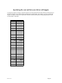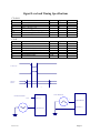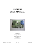
1
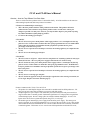
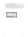
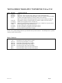
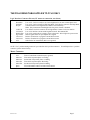
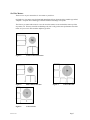
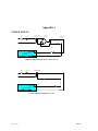
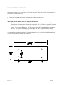
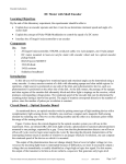
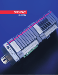
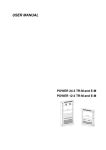
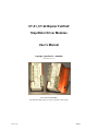
CY-41, CY-42 Bipolar Full/Half
Step Motor Driver Modules
User’s Manual
Copyright CyberPak Co. 1999/2000
Manual Revision 1.32
CY-41 and CY-42 Modules
Note: Bottom mounting flange accessory is available on either model.
Revision 1.31
Page 1
CY-41 and CY-42 User’s Manual
Overview – How Are They Different From Each Other
There are at this time three products in the CY-40 module family. All of the modules are the same size
and mounting footprint and share many features in common.
CY-40 (not recommended for new designs)
• This is the base product similar to other products on the market. This product will not be
enhanced since some customers using similar products want a second source with as few
changes as possible. In many cases however, you may be able to improve your product by using
the enhanced members of this family of products.
• CY-40 uses the sinking type interface.
CY-41 ONLY
• The CY-41 has a low power mode feature which engages about ¾ to 1 second after the last step
pulse it receives. It then reduces to about 50%-60% of its programmed current. In volume OEM
orders it may be possible to accommodate custom specification of either the low power
percentage or the time to low power.
• The CY-41 uses a special circuit technique to increase the running efficiency as compared to the
CY-40.
• The CY-41 uses the sinking type interface
CY-42 ONLY
• The CY-42 runs on AC power. All you need is a transformer AC secondary of about 24 volts, up to
about 30 VAC max. The rest of the power supply is built into the CY-42 driver itself.
• The CY-42 also has a low power mode feature which engages about ¼ second after the last step
pulse it receives. It then reduces to about 50%-60% of its programmed current. In OEM orders
it may be possible to accommodate custom specification of either the low power percentage or the
time to low power.
• The CY-42 uses a special circuit technique to increase the running efficiency as compared to the
CY-40.
• The CY-42 uses a sourcing type interface.
• The CY-42 also has opposite levels for most interface signals due to the sourcing connection (see
CY-42 Logic Interface Connector Pin-Out (page 5)
Features Common to the CY-40, CY41 and CY-42
• The product is a small bipolar chopper drive motor driver module made for OEM product use. We
have gone to some extra effort to enhance your success with this product.
• All input signals are opto coupled. This means that your indexer subsystem and your motor driver
stage need not share a common ground. Furthermore significant over-voltage spikes on signal lines
will not damage inputs. Reverse voltage spikes are tolerated without damaging to -15 volts. The
inputs can be driven from a system that operates using TTL (+5 volt) logic.
• The module gets its internal logic power supply from the motor power supply. The motor power
supply is typically 24-35 volts unregulated DC (AC to 30 vac in the case of the CY-42). This product
uses an efficient on board switchmode DC-DC converter rather than the more commonly used linear
3 terminal regulator. This means we save several watts of dissipation that would otherwise occur,
Revision 1.31
Page 2
•
•
•
which not only unburdens your power supply, but also that your driver module will run cooler or you
can run higher current motors with a smaller heatsink.
The modules have convenient depluggable terminal strips that make replacing modules simple.
The modules have built-in short circuit protection. This serves especially the OEM customer since it
is ‘forgiving’ of potential wiring errors that can occur in every shop.
If you need to operate the module at current levels over 2.5 amps, you may wish to provide some
additional heat sink capability (especially on the CY-40 model). In most cases this could be as
simple as fastening it to your aluminum chassis or using some kind of heat sink extrusion. The CY41 and CY-42 may be run in typical applications without a heat sink, even up to 3.5 amps.
Connecting Your Indexer with CY-40,CY-41,CY-42
5
4
3
2
1
Motor Connector
CY-40 OR CY-41/42 Step Motor Driver
Logic Interface Connector
1
2
3
4
5
6
7
8
9 10
Figure 1
Revision 1.31
Page 3
THE FOLLOWING 2 TABLES APPLY TO EITHER THE CY-40 or CY-41
Logic Interface
Pin #
1
2
3
Function
Run/Reset
Half/Full
Step In
4
5
6
7
8
9
10
CW/CCW
Cir/NonCir
Ena/Disable
5 VDC
Current #1
Current #2
Ground
Connector Pin-out
Notes
High or NC - Driver is ready to run - Pull Low to reset to initial phase state
High or NC - Driver operates in Half Step Mode - Pull Low to operate in Full Step Mode
Transition from High to Pulled Low advances Motor 1 full or half step
Note: This pin must be released after pull down or the low power timeout is inhibited
High defines Clockwise rotation 0 Pulled Low defines Counter-Clockwise rotation
Defines current regulation mode - Normally NC
High or NC permits driver to supply power to the motor - Pulled Low de-powers motor
indexer supplies opto-coupler interface power
Resistor Terminal #1 to program current limit to motor
Resistor Terminal #2 to program current limit to motor
Power ground for step motor power supply
NOTE: The 7 position mating connector is provided for this 5 position connector. If an OEM prefers a 5 position
connector, please contact factory.
Motor Connector
Pin #
1
2
3
4
5
6
7
Function
+ Vm
Motor A1
Motor A2
Motor B1
Motor B2
Spare
Spare
Revision 1.31
Notes
Step Motor power supply positive terminal
First end of step motor phase A winding
Second end of step motor phase A winding
First end of step motor phase B winding
Second end of step motor phase B winding
You could connect extra wire from 6/8 wire motor
You could connect extra wire from 6/8 wire motor
Page 4
THE FOLLOWING TABLE APPLIES TO CY-42 ONLY
Logic Interface Connector Pin-out (NC means no connection, not driven)
Pin #
1
2
3
Function
Reset/Run
Full/Half
Step In
4
5
6
7
8
9
10
CCW/CW
Cir/NonCir
Disable/Ena
Sig Ground
Current #1
Current #2
AC2
Notes
Low or NC - Driver is ready to run - Drive high then low to reset to initial phase state
Low or NC - Driver operates in Half Step Mode - Drive high to operate in Full Step Mode
Transition from Low to High advances Motor 1 full or half step
Note: This pin must not be held high or the low power timeout is disabled.
Low defines Clockwise rotation; driven high defines Counter-Clockwise rotation
Low or NC Defines current normal regulation mode - Recommend NC
Low or NC permits driver to supply power to the motor - Drive high to de-power motor
Indexer signal return for opto-coupler drive signals
Resistor Terminal #1 to program current limit to motor
Resistor Terminal #2 to program current limit to motor
Other End of AC transformer (this is not a ground)
NOTE: The 7 position mating connector is provided for this 5 position connector. If an OEM prefers a 5 position
connector, please contact factory.
Motor Connector
Pin #
1
2
3
4
5
6
7
Function
AC1
Motor A1
Motor A2
Motor B1
Motor B2
Spare
Spare
Revision 1.31
Notes
First AC transformer connection (not a ground)
First end of step motor phase A winding
Second end of step motor phase A winding
First end of step motor phase B winding
Second end of step motor phase B winding
You could connect extra wire from 6/8 wire motor
You could connect extra wire from 6/8 wire motor
Page 5
Connecting Your Motor
First, determine whether your motor is a 4 wire, 6 wire or 8 wire motor. If it is any other number of wires
you may wish to call the factory. Schematics are listed below for each type. To identify the connections
on motors, first refer to the manufactures catalog. Usually there will be a schematic similar to that shown
in one of the following diagrams with the wire colors identified.
Once connected, you may find that the motor rotates in the opposite direction from that you wish it
would. In that case simply exchange the A1 and A2 connection. Do not exchange the wires from both
motor coils, just one coil.
Four Wire Motor
Figure 2
When using a 4 wire motor set the CY-40 OR CY-41 to the same current as the motor current rating.
Six Wire Motors and Eight Wire Motors:
Before discussing them individually, the 6 & 8 wire motors will be discussed together.
CAUTION:
CURRENT RATING ON MOTOR MAY NOT APPLY
First of all there are several ways to connect 6 & 8 wire motors to the 4 terminal connections of the CY40 OR CY-41 BIPOLAR driver. The current rating on the motor is normally defined for a unipolar type
driver and the CY-40 OR CY-41 is a bipolar driver. Please use the following table to determine the
proper current level for your motor and method of connection.
6 Wire
6 Wire
8 Wire
8 Wire
Revision 1.31
Figure 3
Figure 4
Figure 5
Figure 6
set CY-40 OR CY-41 to 100% of motor rating
set CY-40 OR CY-41 to 70% of motor rating
set CY-40 OR CY-41 to 141% of motor rating
set CY-40 OR CY-41 to 70% of motor rating
Page 6
Six Wire Motors:
There are two ways to connect the six wire motor to your driver.
Originally six wire motors were designed and manufactured for an electronic driver module type called
‘unipolar’. Unipolar drive technology is obsolete and has no advantage over bipolar.
The first way to connect this motor is to use the wires that connect to one end and the center tap of the
step motor coil. This may seem like an odd thing to do, but it will give the same performance out of the
motor as if you were to have used the unipolar type driver.
Figure 3
Center to End Connection
Figure 4
End to End Connection
Figure 6
Coils in Series
Revision 1.31
Figure 5
Coils in Parallel
Page 7
Appendix 1
POWER SUPPLY
Power
Switch
3-5 Amp Fuse
Secondary of 24 VAC
with 3 amps or more
100 Volt 5 Amp
Bridge Rectifier
Expect about 30 VDC
unregulated
+
115 VAC
C1
2000 uF (or larger) 24
VDC Electrolytic
Capacitor
DC Ground
+Volts
CY-40/41 Motor
Driver
Ground
Power Supply Example for CY-40 or CY-41
Power
Switch
3 to 5 Amp
Fuse
Secondary of 24 VAC
with 3 amps or more
115 VAC
AC
CY-42 Motor Driver
AC
Power Supply Example for CY-42
Revision 1.31
Page 8
REPLACEMENT CONNECTORS:
If you order the module with the C suffix after the part number (example CY-41C) it will come with a set of
terminal strip connectors. If you need an extra set you are welcome to order them from us. The standard part #’s
are listed here as an alternate source.
•
•
10 position Terminal Block - Newark Stock # 50F3557 (Wieland #25.600.3053.0 )
7 Position Terminal Block - Newark Stock #50F3554 (Weiland 25.600.2753.0 )
MECHANICAL MOUNTING INFORMATION:
The bottom surface of the module should be mounted to a metal chassis or heat sink. The
dimension of the bottom plane of the module extrusion is 3.25 x 1.5 inches. A pattern of 4 holes of
0.90 x 2.00 inches exist centered on this plane. These mounting holes are threaded for 8-32
screws. The extrusion thickness is .125 inch, so you screw can not protrude further than this into
the base. We do have an insulating stop on the other side, but a strong screw driver could go
through this, and that’s not fair.
A recommended screw when mounting to 1/8 inch thick panel is 8-32 x 1/4 FLAT 82 DEGREE (MacMaster
Carr# 91771A190). This is a Philip’s flat head screw.
Revision 1.31
Page 9
Specifying the current that your driver will supply
To program your driver to supply a specific current level, look up the desired current in the first column, then use
the closest available value resistor to that specified in the second column. For example: You have a motor that
requires 2.8 Amps. Look at the 2.8 amp value in the first column, then find the corresponding resistance in the
second column; 7500 ohms.
Current
0.3
0.4
0.5
0.6
0.7
0.8
0.9
1.0
1.1
1.2
1.3
1.4
1.5
1.6
1.7
1.8
1.9
2.0
2.1
2.2
2.3
2.4
2.5
2.6
2.7
2.8
2.9
3.0
3.1
3.2
3.3
3.4
3.5
Revision 1.31
Resistor
69800
56200
44200
37400
31600
27400
24300
21000
20000
18200
16200
15800
14700
13700
12700
11800
11300
10700
10200
9760
9310
8870
8450
8250
7870
7500
7320
6980
6810
6650
6340
6190
5900
Page 10
Signal Level and Timing Specifications
CY-40/41
VIH
VIL
IIH
IIL
TCLK
TS
TH
Opto+ = 5V
Opto+ = 5V
Opto+ = 5V, VIN = 5V
Opto+ = 5V, VIN = 0V
Clock Pulse Width (Rising Edge)
Direction Setup Time
Direction Hold Time
Min
3.0V
Typical
Max
2.0V
0
6 mA
2.0 uS
1.0 uS
4.0 uS
CY-42
VIH
VIL
IIH
IIL
TCLK
TS
TH
Opto Ground = 0V
Opto Ground = 0V
Opto Ground = 0V, VIN = 5V
Opto Ground = 0V, VIN = 0V
Clock Pulse Width (Falling Edge)
Direction Setup Time
Direction Hold Time
Min
3.0 V
Typical
Max
2.0 V
6 mA
0
2.0 uS
1.0 uS
4.0 uS
CY-40/41 Step
CY-42 Step
CW/CCW
Half/Full
TS
T CLK
TH
CY-42 Test Circuit
CY-40/41 Test Circuit
5VDC
Opto+ ( 7 )
-
-
Input Under Test
+
Input Under Test
Revision 1.31
+
Opto Gnd ( 7 )
Page 11