1
HS-20USB
USER MANUAL
Copyright 2007
Cyberpak Company Inc.
All Rights Reserved
Revision Date: July 2007
Revision 1.39
CyberVec Revision 5.67
HS-20USB_REV_139.odt
Rev 1.39
Page 1 of 61
Table of Contents
Introduction.............................................................................................................................................7
Features...................................................................................................................................................7
Manual Organization.............................................................................................................................. 7
Hardware Reference Manual......................................................................................................................8
Connector Summary............................................................................................................................... 8
Communications..................................................................................................................................... 8
Introduction......................................................................................................................................... 8
Communications Configuration Options.............................................................................................9
Host USB Port Direct (Additional Attachments via USB Hub).................................................. 9
Host COM Port Direct (Optional RS-232 Multi-Drop).............................................................10
Host USB Port Direct with Serial Multi-Drop Expansion.........................................................11
Stand-Alone with Optional RS-232 Multi-Drop........................................................................11
RS-232 Connector (J402) Pin Definitions............................................................................................ 12
Power Connector (J501) Pin Definitions ............................................................................................. 12
Motor Control Connector (J201) Pin Definitions................................................................................. 13
Expansion Port Connector (J301) Pin Definitions................................................................................15
Analog and Encoder Interface Connector (J601) Pin Definitions ....................................................... 16
High Current Sinking Outputs (J701) Pin Definitions......................................................................... 17
Jumper Summary.................................................................................................................................. 17
CyberVec Reference Manual................................................................................................................... 18
Overview...............................................................................................................................................18
CyberVec Dialog Characteristics..........................................................................................................18
The Basic Programming Environment................................................................................................. 19
Using the PC to Create and Edit CyberVec Programs..........................................................................20
Downloading Programs from the PC to the HS-20USB...................................................................... 21
Programming Environment Advanced Topics..................................................................................... 21
HS-20USB Addressing......................................................................................................................... 22
Status at Power Up................................................................................................................................23
Special Characters/Character Sequences.............................................................................................. 23
Command Parameters/Arguments........................................................................................................ 23
Immediate vs. Buffered Commands..................................................................................................... 24
Command Documentation Assumptions.............................................................................................. 25
Command Documentation Format....................................................................................................... 25
CyberVec Commands.......................................................................................................................... 26
Motor and Motion Control Commands............................................................................................. 26
AN - Accelerate No................................................................................................................... 26
ANG <Mode> - Set Angle Restriction Mode............................................................................ 26
AY - Accelerate Yes.................................................................................................................. 26
CE <Axis> - Clear Encoder Position Register...........................................................................26
CEP <Axis> <Encoder Scale Factor> <Acceptable Tolerance> - Compare Encoder Position.26
CTP <Axis> <Position> <Multiplier> - Compute Target Position........................................... 26
DN - Decelerate No................................................................................................................... 27
DY - Decelerate Yes.................................................................................................................. 27
E0 / E1 - Enable Mode Polarity................................................................................................ 27
ENC <On/Off> - Encoder Subsystem Enable........................................................................... 27
HS-20USB_REV_139.odt
Rev 1.39
Page 2 of 61
EP <Axis> <Encoder Position> - Set Encoder Position............................................................ 27
GO - Go to Absolute Target Position....................................................................................... 27
HLT <Axis Mask> - Halt Motor Axis....................................................................................... 27
JD<a><b> - Joystick Digital Control Mode Begin....................................................................28
L <Axis> <xxxxxx> - Set Location...........................................................................................28
LD <Axis> - Limit Disable........................................................................................................28
LE <Axis> - Limit Enable......................................................................................................... 28
NCL - Normally Closed Limits................................................................................................. 28
NOL - Normally Open Limits....................................................................................................28
LM <Mask> - Limit Mask......................................................................................................... 29
LN - Location No.....................................................................................................................29
LY - Location Yes.................................................................................................................... 29
MPN <Axis> - Motor Power No............................................................................................... 29
MPY <Axis> - Motor Power Yes.............................................................................................. 29
QE <Axis> <Scale Factor> - Query Encoder Position Register...............................................29
QES <Axis> <Scale Factor> - Query Encoder Scaled............................................................. 29
QL <Axis> - Query Location.....................................................................................................30
QLS <Axis> <Motor Scale Factor> - Query Location Scaled................................................. 30
QM <Axis> - Query Motion Status........................................................................................... 30
R <int> - Rate............................................................................................................................ 30
RCN - Run Continuous No........................................................................................................ 30
RCY - Run Continuous Yes.......................................................................................................30
RN - Ramping No...................................................................................................................... 31
RQ <int> - Rate Quick...............................................................................................................31
RTM <N> - Read Timer............................................................................................................ 32
RY - Ramping Yes.....................................................................................................................32
SAPU <Position> - Set Absolute U Axis Position.................................................................... 32
SAPX <Position> - Set Absolute X Axis Position.................................................................... 32
SAPY <Position> - Set Absolute Y Axis Position.................................................................... 32
SAPZ <Position> - Set Absolute Z Axis Position..................................................................... 32
SEP <Axis> <Encoder Scale Factor> - Subtract Encoder Position...........................................32
SLC <int> - Set Location Counter .......................................................................................... 32
SLD <arg> - Slow Mode Divisor ........................................................................................... 32
SLN - Slow Mode No................................................................................................................ 32
SLY- Slow Mode Yes................................................................................................................32
SME <Axis> <Scale Factor> - Set Motor to Encoder Position.................................................33
SR <Ramp ID> - Select Ramp...................................................................................................33
STL <Mode> - Stall Detect Enable/Disable.............................................................................. 33
STM <N> <Type> <Pin> <Time> - Set Timer....................................................................... 34
TR1 <data space #> <pin#> - Trigger Pulse Enable Channel #1.............................................. 34
TR2 <data space #> <pin#> - Trigger Pulse Enable Channel #2.............................................. 34
U=<int> - Set Absolute Position Target for U Axis.................................................................. 35
Vn <Axis> <Steps> . . . [<Axis> <Steps>] - Vector Relative Move.......................................35
WTM <N> <Time> - Wait for Timer........................................................................................35
X=<int> - Set Absolute Position Target for X Axis.................................................................. 35
Y=<int> - Set Absolute Position Target for Y Axis.................................................................. 35
Z=<int> - Set Absolute Position Target for Z Axis................................................................... 35
HS-20USB_REV_139.odt
Rev 1.39
Page 3 of 61
Input/Output & Control Panel Interface Commands.........................................................................36
BCD <Type> <Pin> <Switches> - Read BCD.......................................................................... 36
DCN - Display Cursor No..........................................................................................................36
DCY - Display Cursor Yes........................................................................................................ 36
DDI <Row> <Col> <Width> <Value> <DPP> - Display Decimal Integer.............................. 37
DE - Display Enable.................................................................................................................. 37
DI <Row> <Col> <Width> <Int> - Display Integer................................................................. 37
DS <Row> <Col> <Width> <String> - Display String.............................................................37
FCF - Flush Character FIFO ..................................................................................................... 37
GCM - Get Character from Matrix Keypad...............................................................................37
GCS - Get Character from Serial Port...................................................................................... 37
GDM <Row> <Col> <Width> <DPP> - Get Decimal Matrix................................................. 38
GIM <Row> <Col> <Width> - Get Integer from Matrix Keypad........................................... 38
GIS - Get Integer from Serial Port.............................................................................................38
GSM - Get the Scan Code for a Matrix Keyboard.....................................................................38
IB <Type> <Pin> <Width> - Input Bits.................................................................................... 38
IIO <Type> <Value> - Initialize for J301 Digital I/O............................................................... 39
OB <Type> <Pin> <Width> <Value> - Output Bits................................................................. 39
OSC <int> - Output Character to Serial Port............................................................................. 40
OSD <int> - Output Decimal to Serial Port...............................................................................40
OSI <int>- Output Integer to Serial Port................................................................................... 40
OSS "string"- Output String to Serial Port.................................................................................40
OUT <x> - Output Number to Serial Port................................................................................. 40
QAX <Analog Channel Address> - Query 8 Bit Analog Channel...........................................40
QK - Query Matrix Keyboard....................................................................................................40
QSC - Query Serial Count......................................................................................................... 40
RDY- Ready I/O........................................................................................................................ 41
Arithmetic & Logic Commands........................................................................................................ 42
ABS <Integer> - Absolute Value...............................................................................................42
ADD <Value1> <Value2> - Add two Values......................................................................... 42
ADP <Integer> - Add to Pointer................................................................................................42
AND <Integer1> <Integer2> - Logically Bitwise And Two Values......................................... 42
BIT <Value> <Bit> - Bit Test Instruction................................................................................. 42
BRK - Break Out of Program Loop...........................................................................................42
BRO <Offset> <Table> - Branch on Offset into Table............................................................. 43
CAL <Prog> - Call Program.....................................................................................................43
CLO <Offset> <Data Space - Call with Offset..........................................................................44
COM <Int> - Complement Bits................................................................................................ 44
DIV <Int1> <Int2.......................................................................................................................44
DP- Decrement Pointer.............................................................................................................. 44
DUP- Duplicate Top Stack Item................................................................................................ 44
EQ <int1> <int2> - Test for Equality........................................................................................ 44
FOR <arg1> {loop commands} - FOR Loop Statement.......................................................... 44
GT <int1> <int2> - Greater Than Test..................................................................................... 45
IDV <Numerator> <Denominator> - Signed Integer Divide.................................................... 45
IF arg1 { [optional true clause ] ? [ optional false clause]} - If Conditional Statement......... 45
IP - Increment Pointer................................................................................................................45
HS-20USB_REV_139.odt
Rev 1.39
Page 4 of 61
LT <int1> <int2> - Less Than.................................................................................................. 45
MUL <int1> <int2> - Multiply..................................................................................................46
NEG <int> - Negate................................................................................................................... 46
NXT - NEXT ........................................................................................................................... 46
OR <int1> <int2> - Logically Bitwise OR............................................................................... 46
POP- Pop Pointer....................................................................................................................... 46
PUP- Push Pointer......................................................................................................................46
RET- Return from CAL............................................................................................................. 47
RP - Read Value at Pointer........................................................................................................ 47
RV <var> - Read Variable......................................................................................................... 47
SP <int> - Set Pointer to Program Space................................................................................... 47
SUB <int1> <int2> - Subtract....................................................................................................47
SUP <integer> - Subtract Pointer.............................................................................................. 47
SWP - Swap.............................................................................................................................. 47
WHL <arg1> { loop commands} - While Loop...................................................................... 47
WP <int> - Write Value to Pointer............................................................................................ 48
WV <var> <int> - Write Variable............................................................................................. 48
General/System Commands............................................................................................................. 49
<ESC> - Abort/Interrupt Program............................................................................................. 49
@<ESC> - GLOBAL ESCAPE ................................................................................................49
AB - Abort................................................................................................................................. 49
AIc - Acknowledge Immediate.................................................................................................. 50
AKc - Acknowledge Buffered .................................................................................................. 50
AR - Address Read ................................................................................................................... 51
CR <Ramp> - Checksum Ramp ............................................................................................... 51
D <Int> - Delay .........................................................................................................................51
DD <Prog> - Data Dump..........................................................................................................51
DL <Prog> <Count>- Data Load ..............................................................................................51
DOB - Dump Output Buffer...................................................................................................... 52
DR <Ramp> <Count> - Download Ramp................................................................................. 52
EN - Echo No.............................................................................................................................52
EY - Echo Yes........................................................................................................................... 52
FL - Flush Buffer ...................................................................................................................... 52
PC <Prog> - Program Checksum...............................................................................................52
PD <Prog> - Program Dump ................................................................................................... 53
PL <Prog> - Program Load....................................................................................................... 53
PO - Pop the Stack..................................................................................................................... 53
PU <int> - Push Value onto Stack............................................................................................. 53
PV <Prog> - Program Verify.....................................................................................................53
PX <Prog> - Program Execute.................................................................................................. 53
QF - Query Flags....................................................................................................................... 54
QI - Query Instruction Count.....................................................................................................54
QS - Query Sense/Limit Inputs..................................................................................................54
QV - Query Version Number ....................................................................................................55
RES <Area> - Restore RAM..................................................................................................... 55
RST - Reset................................................................................................................................ 55
SAV <Area> - Save RAM......................................................................................................... 55
HS-20USB_REV_139.odt
Rev 1.39
Page 5 of 61
ST - Self Test............................................................................................................................. 55
WC - Wait For Commands to Finish......................................................................................... 56
WOH <Type> <Mask> - Wait On High...................................................................................56
WOL <Type> <Mask> - Wait On Low.................................................................................... 56
WPH <Type> <Pin> - Wait For a Pin to Go High.................................................................. 56
WPL <Type> <Pin> - Wait For a Pin to Go Low.................................................................... 57
Internal Commands........................................................................................................................... 58
ID - Immediate Disable .............................................................................................................58
IE - Immediate Enable .............................................................................................................. 58
QR - Query Rate........................................................................................................................ 58
QT - Query Ramp Table Characteristics .................................................................................. 58
RD - Rate Down ........................................................................................................................59
RH <int> - Rate Home...............................................................................................................59
RI <int> - Rate Immediate......................................................................................................... 59
RS <int> - Rate Slew................................................................................................................. 59
RU - Rate Up............................................................................................................................. 59
APPENDIX A.......................................................................................................................................... 60
Installation of USB Driver Software on Host PC................................................................................. 60
HS-20USB_REV_139.odt
Rev 1.39
Page 6 of 61
Introduction
The HS-20USB is a 3.9" x 6.0" circuit board on which has been implemented a 4-axis step motor
indexer/controller with USB 2.0 interface. It can control up to 4 step motors via external step and
direction driver cards operating in full or half step mode. The HS-20USB, in turn, can be controlled
directly from a host PC by downloading commands to it via the USB interface, or it can operate standalone by executing a previously downloaded program. In either case -- immediate or stored program
execution -- the command set utilized is CyberVec, a powerful, text string-based language which the
HS-20USB can interpretively execute and which includes commands for step motor control, digital and
sensor I/O, control panel I/O, arithmetic, branching, and looping.
Features
•
•
•
•
•
•
•
•
•
•
•
•
•
•
•
4 axis control via external step and direction / full or half step driver cards
Can be used with any step and direction interface driver card including CyberPak's own CY-41
and/or CY-42
Encoder support for each axis
USB 2.0 interface operating in serial/RS-232 emulation mode
Auxiliary RS-232 serial port which can be used in place of the USB interface for host PC
communication and/or as a means of muti-drop connectivity for up to 7 additional HS-20USB
boards
Module address switch for use in multi-drop configurations
Embedded CyberVec interpreter
Direct control from PC (or PLC) via immediate execution of CyberVec commands
Stand-alone operation via execution of previously downloaded CyberVec program
Non-volatile FLASH storage for CyberVec programs and parameters
8-12 V unregulated or 5V regulated logic supply option
12 digital inputs with built-in support for joystick/limit switch control
4 8-bit analog inputs
8 open drain outputs which can drive relays, solenoids, and other small loads
Built-in support for a local control panel (10 key keypad, LCD display, thumbwheel)
Manual Organization
This manual is divided into the following sections:
•
•
•
Hardware Reference Manual
CyberVec Reference Manual
Appendix A - Installation of USB Driver Software on Host PC
HS-20USB_REV_139.odt
Rev 1.39
Page 7 of 61
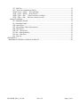
Hardware Reference Manual
Connector Summary
•
•
•
•
•
•
•
USB - J401
Serial Port – J402
Power - J501
Motor Indexing - J201
Aux I/O - J301
Encoder – J601
Solenoid Outputs – J701
Communications
Introduction
The USB interface of the HS-20USB operates in serial/RS-232 emulation mode utilizing technology
provided by semiconductor manufacturer FTDI (www.ftdichip.com). In this approach, an FTDI chip
HS-20USB_REV_139.odt
Rev 1.39
Page 8 of 61
on the HS-20USB board and FTDI software on the host PC (see Appendix A for installation
instructions) cooperate to make the USB link emulate a standard RS-232 connection. Indeed, the FTDI
software on the PC end actually creates a "virtual" COM port which can be utilized by any PC
application -- such as Hyperterminal -- as if it were a real RS-232 COM port.
As such, it possible to use Hyperterminal to type CyberVec command strings into the HS-20USB for
immediate execution. Alternatively, a PC program written in C or Basic can open a virtual COM port
and send CyberVec commands to the HS-20USB for execution. As a third alternative, the CyberPak
host utility HSL.EXE ("HS Link") can be used to 1) download a bulk CyberVec program to the HS20USB for subsequent execution, or 2) upload a CyberVec program from the HS-20USB for backup or
editing on the host PC.
If an actual RS-232 COM port is available on the host PC, the auxiliary RS-232 port on the HS-20USB
can be interchageably used in place of the USB port for communications.
When USB communication is used, the serial data converted from the USB link is also mirrored on the
axillary serial port of the HS-20USB.
With this overview, the following section will detail each of the several possible comm configurations.
Communications Configuration Options
•
•
•
•
Host USB Port Direct (Additional Attachments via USB Hub)
Host COM Port Direct (Optional RS-232 Multi-Drop)
Host USB Port Direct with Serial Multi-Drop Expansion
Stand-Alone with Optional RS-232 Multi-Drop
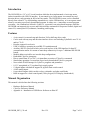
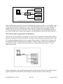
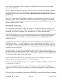
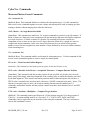
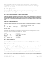
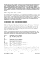
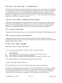
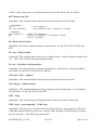
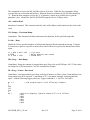
Host USB Port Direct (Additional Attachments via USB Hub)
In cases where there is only one HS-20USB the host interface is as simple as connecting a standard
USB cable from the computer to the HS-20USB:
Computer
USB
HS20-USB
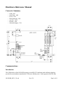
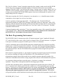
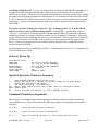
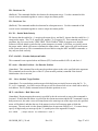
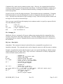
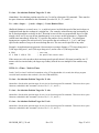
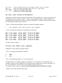
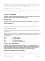
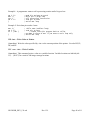
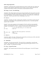
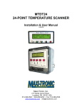
Additional HS-20USB's can be connected using a USB hub or additional USB ports on the computer:
HS-20USB_REV_139.odt
Rev 1.39
Page 9 of 61
USB
Computer
USB
USB HUB
USB
HS20-USB #1
HS20-USB #2
(O ption al)
USB
HS20-USB #N
(O ption al)
(T he USB HUB could be inside of computer)
Such a configuration is possible because the FTDI host driver software is able to create multiple virtual
COM ports and logically connect each to a specific HS-20USB board based on a unique hardware ID
number built into each of its USB interface chips. In the above illustration, for example, a virtual
COM1 (which can be used just as if it were a real COM port) might be created and linked logically to
the #1 HS-20USB board, a virtual COM2 might be created and linked to the #2 HS-20USB, and so on.
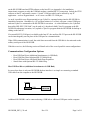
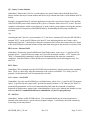
Host COM Port Direct (Optional RS-232 Multi-Drop)
If the host PC has an actual RS-232 COM port, it can be used to communicate with the HS-20USB via
the latter's auxiliary RS-232 port. The RS232 connection is made using the 10 pin header (J402) on the
PC board and matching connections with a computer DB9 connector. (A DB9 to IDC10 adapter cable
is needed for the RS232 connection to the computer). Additional units may be multi-dropped along
this same RS 232 bus. Each HS-20USB must be given a unique address in the range 0 - 7 via its
address select switch.
In this configuration, a special (although not expensive) RS-232 multi-drop cable is needed which ties
together in parallel the TXD, RXD, and GND pins of each HS-20USB, as shown following:
HS-20USB_REV_139.odt
Rev 1.39
Page 10 of 61
Please consult CyberPak (800-328-3938) for assistance with multi-drop configurations.
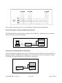
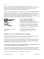
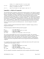
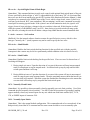
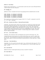
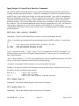
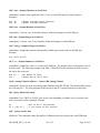
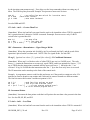
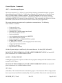
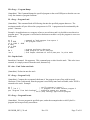
Host USB Port Direct with Serial Multi-Drop Expansion
The first HS-20USB is connected to the computer with a USB cable. Additional units are connected
off the first HS20 via RS-232 multi-drop.
Computer
HS20-USB #2
USB
HS20-USB #1 RS232
HS20-USB #X
(O ption al)
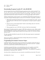
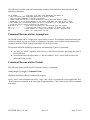
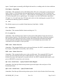
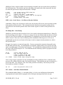
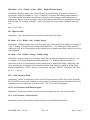
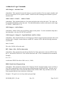
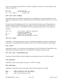
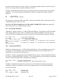
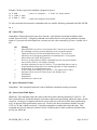
Stand-Alone with Optional RS-232 Multi-Drop
In this configuration a computer is not needed. The master unit can control slave units via the RS-232
interface. (Consult CyberPak for this configuration.) Of course slave units are not required; a single
HS-20USB can operate stand-alone to control up to 4 step motors.
HS20-USB #2
HS20-USB #1 RS232
HS20-USB #X
(O ption al)
Master
HS-20USB_REV_139.odt
Slaves
Rev 1.39
Page 11 of 61
Please consult CyberPak (800-328-3938) for assistance with multi-drop configurations.
RS-232 Connector (J402) Pin Definitions
RS232 Header and Computer Serial DB9 Pinout
J402
DB-9
Definition
3
2
Master Mode: RxD, Slave Mode: TxD
4
7
RTS (Loop Back to CTS)
5
3
Master Mode: TxD, Slave Mode: RxD
6
8
CTS (Loop Back to RTS)
7,8,9,10
1,4,6,9
N.C.
9
5
GND
A host controller can be configured to use Pins 7 and 8 to verify cable plugged in. To use this serial
port you must configure your terminal or PC serial port to match these HS-20USB settings. Select the
port to be used and set for 8 data bits, 1 stop bit, no parity, and a baud rate of 19200. The HSL.EXE
utility is preset with these attributes.
Power Connector (J501) Pin Definitions
Pin #
Definition
1
8 -12 V unregulated. at .5 A (or +5 volts regulated using jumper JP501)
2
Ground
3
Not used -- keyed
RS-232 Supply (Isolated)
4
Ground (isolated)
5
- 12 V at 50mA
6
+ 12 V at 50mA
Logic power (and, optionally, RS-232 power) is supplied to the HS-20USB via connector J501. A
mating female connector is also provided. Pin 1 is toward the edge of the board.
If jumper JP501 is shorted between pins 2 and 3 (those closest to the U501 7805 5 V regulator), the
HS-20USB expects a logic power input of 8-12 V unregulated; this is the factory default setting. If
jumper JP501 is shorted between pins 1 and 2, the HS-20USB is expects a logic power input of 5V
regulated.
DANGER
Severe damage will occur if JP501 set for 5 V regulated input and 8-12 V unregulated supplied instead.
HS-20USB_REV_139.odt
Rev 1.39
Page 12 of 61
Motor Control Connector (J201) Pin Definitions
J201 is the HS-20USB motor control interface. It allows the connection of the HS-20USB to any
device that uses the standard step and direction interface. Pin 1 is marked by an arrow on the
connector. The pin numbers then alternate, pin 1 is first pin top row, pin 2 is first pin bottom row and
so on, such that all of the even pins are in one row, odd in the other.
Pin #
1
2
3
4
5
6
7
8
9
10
11
12
13
14
15
16
17
18
19
20
21
22
23
24
25
26
Name
Step 0
Direction 0
Step 1
Direction 1
Step 2
Direction 2
Step 3
Direction 3
Ground
Enable 3
CW Limit 0
CCW Limit 0
Index 0
CW Limit 1
CCW Limit 1
Index 1
CW Limit 2
CCW Limit 2
Index 2
CW Limit 3
CCW Limit 3
Index 3
+ 5 V Source
Enable 0
Enable 1
Enable 2
Function
Step pulse for motor 0
Direction for motor 0
Step pulse for motor 1
Direction for motor 1
Step pulse for motor 2
Direction for motor 2
Step pulse for motor 3
Direction for motor 3
Enable for motor 3
Clockwise limit for motor 0
Counter clockwise limit for motor 0
Index/Mark input for motor 0
Clockwise limit for motor 1
Counter clockwise limit for motor 1
Index/Mark input for motor 1
Clockwise limit for motor 2
Counter clockwise limit for motor 2
Index/Mark input for motor 2
Clockwise limit for motor 3
Counter clockwise limit for motor 3
Index/Mark input for motor 3
250 mA Max total for all pins
Enable for motor 0
Enable for motor 1
Enable for motor 2
Signal Definitions
Enable:
Enable is an active high signal. When this signal is high the motor is enabled. When it
is low the motor is disabled. (This can be reversed; see CyberVec E0 and E1
commands.)
Step:
On the rising edge of the step signal the motor will take a step.
Direction:
When this signal is high the motor will rotate clockwise and when this signal is low the
motor is in counter clockwise rotation mode.
CW Limit:
When pulled low, this motor input signifies that a limit of travel has been reached in the
clockwise direction. If limit checking was enabled this axis will stop and move in the
HS-20USB_REV_139.odt
Rev 1.39
Page 13 of 61
counter clockwise direction as stated under the limit enable command in the
indexer/controller manual. The NCL instruction reverses the definition of this input.
CCW Limit: When pulled low, this motor input signifies that a limit of travel has been reached in the
counter clockwise direction. If limit checking was enabled this axis will stop and move
in the clockwise direction as stated under the limit enable command in the HS-20
indexer/controller manual. The NCL instruction reverses the definition of this input.
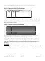
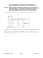
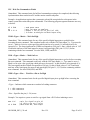
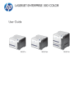
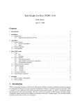
Following is a diagram showing how joystick and limit switch imputs could be wired into J201:
It is possible to choose normally closed or normally open axis limit switches. If the former, one MUST
take the precaution of 'grounding' (making appear normally closed) any unused inputs for any axis
which runs with limits enabled (LE), CCW, CW, or INDEX inputs of connector J201. (See CyberVec
NCL (Normally Closed Limits) command.)
If operating with normally closed switches, unused inputs are pulled high on the circuit board, so
nothing needs to be done with them
HS-20USB_REV_139.odt
Rev 1.39
Page 14 of 61
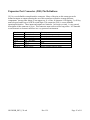
Expansion Port Connector (J301) Pin Definitions
J301 is a user definable external interface connector. Many of the pins on this connector can be
defined as inputs or outputs allowing the use of this connector to interface to many different
components. Among other things it can support are 1) a 4 line, 40 character LCD display; 2) a 20 key
matrix keypad, and/or up to 16 BCD switch digits. This connector (J301) is a user definable
input/output interface. These inputs and outputs are limited to 1 mA source or sink. A very general
description of this connector is given. This connector must not be used for long cables. It is intended
as an electronic to electronic interface in a very protected environment.
Pin #
1-8
9
11-18
19-21
22
23
24-26,10
Name
IOA0 - IOA7
Ground
IOB0 - IOB7
IN1 - IN3 Input
IOC3
+5V
IOD0 -IOD3
HS-20USB_REV_139.odt
Function
Byte definable input or output
Byte definable input or output
Input
Nibble definable input or output
Rev 1.39
Page 15 of 61
Analog and Encoder Interface Connector (J601) Pin Definitions
Pin #
1
2
3
4
5
6
Name
Analog0
Analog1
Analog
Analog
AnalogV+
AnalogGnd
Definition
Analog input, 8 bit ADC
Analog input, 8 bit ADC
Analog input, 8 bit ADC
Analog input, 8 bit ADC
Analog Supply/Reference Voltage
Analog Ground Supply/Reference
7
8
9
10
11
Encoder0A
Encoder0B
Encoder0I
+5 Volt
Ground
Encoder Channel 0, Phase A
Encoder Channel 0, Phase B
Encoder Channel 0, Index
Power Supply Source Voltage
Power Supply Ground
12
13
14
15
16
Encoder1A
Encoder1B
Encoder1I
+5 Volt
Ground
Encoder Channel 1, Phase A
Encoder Channel 1, Phase B
Encoder Channel 1, Index
Power Supply Source Voltage
Power Supply Ground
17
18
19
20
21
Encoder2A
Encoder2B
Encoder2I
+5 Volt
Ground
Encoder Channel 2, Phase A
Encoder Channel 2, Phase B
Encoder Channel 2, Index
Power Supply Source Voltage
Power Supply Ground
22
23
24
25
26
Encoder3A
Encoder3B
Encoder3I
+5 Volt
Ground
Encoder Channel 3, Phase A
Encoder Channel 3, Phase B
Encoder Channel 3, Index
Power Supply Source Voltage
Power Supply Ground
Signal Defintions
Analog Inputs:
Analog input signals between 0 and 5 volts are accepted by an 8 bit analog to digital
converter producing a single byte result in the range 0-255.
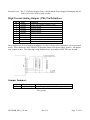
Encoder Inputs: The encoder generates two pulse wave forms that are 90 degrees out of phase. These
inputs are used to monitor shaft movement and direction. The on board encoder
circuit multiplies the encoder's 'line count' by four (4X). This means that if you have
a 1000 line per revolution encoder, you will get 4000 counts per revolution. The
encoder inputs are compatible with open collector or TTL type encoders.
Encoder Index:
Many encoders have a signal which produces a pulse each revolution. This signal
may be connected to the encoder index pin, however the HS-20USB firmware does
not make direct use of this input. You may also wish to use it as a general purpose
input.
HS-20USB_REV_139.odt
Rev 1.39
Page 16 of 61
Encoder Power: The +5 volt Power Supply Source voltage and the Power Supply Ground pins may be
used to power the circuit on each encoder.
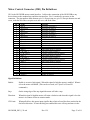
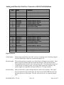
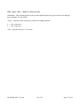
High Current Sinking Outputs (J701) Pin Definitions
Pin #
1
2
3
4
5
6
7
8
9
10
Name
External V+
Output2
Output3
Output4
Output5
Output6
Output7
Output8
Output9
Ground
Definition
User's power supply (typically +24V)
Sinking Output
Sinking Output
Sinking Output
Sinking Output
Sinking Output
Sinking Output
Sinking Output
Sinking Output
Return
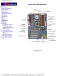
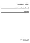
These outputs may be used with small inductive or resistive loads, such as pneumatic valves and small
relays. These outputs are NOT PROTECTED against shorts to the power supply positive. All outputs
may conduct at once. The following wiring diagram shows an example of how J701 may be used:
Jumper Summary
JP #
501
Name
Logic Pwr Supply
HS-20USB_REV_139.odt
Definition
1-2 = 5V regulated; 2-3* = 8-12V unregulated
* positions 2 and 3 are closest to the 3 terminal
7805 regulator
Rev 1.39
Page 17 of 61
CyberVec Reference Manual
Overview
CyberVec is a complete, text-based language for controlling the operation of a step motor system. As
such, it includes not only motion control commands, but also commands for digital and sensor I/O;
control panel I/O; arithmetic and logic; branching and looping; host PC (terminal style) I/O; and
program management. In total, the CyberVec language includes more than 150 separate commands.
An interactive CyberVec interpreter forms the core of the HS-20USB firmware. As such, the term
"CyberVec" as used herein can refer not only to the CyberVec language, but also to this interpreter -and, by extension, to the HS-20USB itself. For example, if this manual states that "CyberVec provides
128 separate program 'spaces' numbered 0 through 127", what is really meant is that "the HS-20USB,
acting in its capacity as a CyberVec interpreter, provides 128 separate program 'spaces' numbered 0
through 127".
As with the BASIC programming environment, the HS-20USB CyberVec interpreter can execute
commands interactively as they are presented via the USB (or RS-232) interface; or, the interpreter can
accept a complete CyberVec program and store it in flash memory for subsequent (i.e., upon power-up)
execution.
Note also that the CyberVec commands downloaded to the HS-20USB do not have to be entered by a
human operator; quite often, for example, they are generated by a C or BASIC language supervisory
program running on the host PC .
CyberVec Dialog Characteristics
The dialog between the host PC and the selected HS-20USB is basically an ASCII, terminal-mode
dialog (although, as noted, the host end of the dialog can be generated by a BASIC or C language
program rather than a human operator).
Given that you have your PC connected to the HS-20USB via a virtual (see Appendix A) or actual
comm port, a program such as HyperTerminal (one of the Windows "accessories") can be used to make
your PC emulate a terminal: each character you type on the keyboard is transmitted to the HS-20USB,
anc each charcter transmitted by the HS-20USB is displayed on your screen.
If the HS-20USB auxiliary RS-232 port is being used to connect with the PC host, the host COM port
must be set to 19200 baud, 8 data bits, 1 start bit, 1 stop bits, and software flow control (i.e., XON
[Ctrl-Q] / XOFF [Ctrl-S] ).
The CyberVec interpreter can be switched, via the EY and EN commands, between echo and non-echo
mode. The former is more appropiate for the human operator, who needs feedback while typing; the
latter is more appropriate when the CyberVec commands are being generated by a C or BASIC
program.
HS-20USB_REV_139.odt
Rev 1.39
Page 18 of 61
The CyberVec dialog is "stream" oriented as opposed to line oriented; in other words, the HS-20USB
will, in many cases, act upon a meaningful sequence of characters before it has received a RET
character. (The ASCII "RET" key [from the old Teletype "carriage return"] is usually labeled "ENT" or
"ENTER" on PC keyboards, and is so referred to elsewhere in this manual.) Likewise, CyberVec will
in many cases not output a RET/LINE FEED sequence where one would normally be expected. (See
sample dialog below for examples.)
With some exceptions, the CyberVec interpreter is case insensitive, i.e., it shouldn't matter whether
commands are sent in upper case or lower case letters.
CyberVec maintains a fairly large input buffer -- 256 characters total. The HS-20USB will
automatically transmit an XOFF [Ctrl-S] character if this buffer reaches its "high water" mark of 200
characters, and will automatically transmit an XON [Ctrl-Q] character when CyberVec processing has
reduced the number of characters in this buffer to its "low water" mark of 150 characters. The abort
commands flush this buffer.
Comments beginning with a semicolon (";") have been appended to many of the command lines shown
in the examples below. These are for instructional purposes only and must not be transmitted to
an HS-20USB as it will attempt to interpret them as actual commands.
The Basic Programming Environment
The HS-20USB CyberVec interpreter provides 128 separate program "spaces" numbered 0 through
127, each of which is able to store a short CyberVec program of up to 250 total characters. A program
in one space can chain to a program in another space, or call it as a subroutine.
CyberVec statements sent to an HS-20USB in interactive terminal mode can be stored in a specified
program space via the PL (program load) command. Conversely, the PD (program dump) command
will cause the contents of a particular program space to be output in text format by the HS-20USB via
the terminal mode link. And, the PX command causes program execution to begin at the specified
program space.
Each CyberVec program segment (i.e., the program occupying one program space) must be terminated
by a text line consisting of a single ASCII period (hex 2E). (Note that many of CyberVec
programming examples shown in this manual are not complete program segments but rather a few
consecutive commands extracted from a larger program; hence, they are not terminated with a period.)
As a program is being stored into a particular space, a checksum is computer for it and stored
separately. This provides a subsequent method for checking program validity.
All of the above described CyberVec program development and execution takes place in RAM. The
SAV 1 command can be then be used to store the complete set of 128 programming spaces to flash
memory. Upon power-up, the RAM program spaces are restored automatically from flash. If program
space 0 is then found to contain a valid CyberVec program (as determined by recomputing its
checksum and comparing against the stored value), it is automatically executed. This program
will typically perform certain initialization housekeeping, and will then invoke programs stored in other
HS-20USB_REV_139.odt
Rev 1.39
Page 19 of 61
spaces.
There is no requirement that HS-20USB applications occupy consecutive program spaces -- it is
perfectly legal, for example, to have an application that lives in program spaces 0, 1, 2, and 117. The
only thing to keep in mind is that if you want your application to auto-start on power up, the
initialization segment, as noted above, must reside in program space 0.
Following is a typical dialog 1) to enter a two-line CyberVec program (which simply outputs "HELLO,
WORLD!" and then "GOODBYE!"), 2) to verify that the program has been correctly entered by a)
having it re-output to the serial port and b) actually executing the program, and 3) to save the program
to flash memory. When the power is cycled on the HS-20USB, the program is then executed
automatically. User input in shown in bold face, and <ENT> indicates the "Enter" key. Keep in mind
that the semicolon-delimited comments cannot actually be sent to the HS-20USB:
PL 0<ENT>
OSS "HELLO, WORLD!"<ENT>
OSS "GOODBYE!"<ENT>
.<ENT>
PD 0<ENT>
OSS "HELLO, WORLD!"
OSS "GOODBYE!"
.PX 0<ENT>
HELLO, WORLD!
GOODBYE!SAV 1<ENT>
D
;
;
;
;
;
;
set to enter a program for space 0
enter a simple print command
enter a second print command
the program must be terminated by a "."
enter the cmnd to "dump" the program 0 space
the program is output by the HS-20USB
;
;
;
;
enter the cmnd to execute the prog 0 space
the program is executed by the HS-20USB
enter the cmnd to save pograms to flash
HS-20USB outputs a "D" when finished saving
; now cycle power to the HS-20USB
(C)CYBERVEC V5.67EU-PROG128
HELLO, WORLD!
GOODBYE!
; HS-20USB first outputs its "banner"
; it then automatically executes program
; in program space 0 (if any)
Using the PC to Create and Edit CyberVec Programs
CyberVec programs will quickly reach a size where it is easier to create and edit them on a PC, with
the programs then being downloaded to the HS-20USB for test and execution.
Inasmuch as CyberVec is text based, CyberVec programs can be managed as simple text files on the
PC, with a separate text file for each CyberVec program space. For example, if you develop your
application such that it occupies program spaces 0, 1, 2, and 3, the corresponding PC files could be
named "APP.V000", "APP.V001", "APP.V002", and "APP.V003".
It is critical that these program text files be created and edited with a Notepad-type editor, i.e., an
editor which does not introduce non-ASCII formatting codes etc..
Two other points should be kept in mind as well: 1) the semicolon-delimited comments shown in this
manual are for instructional purposes only, and must not be included in the CyberVec program text
itself; and 2) each CyberVec program segment must be terminated by a line containing a single period.
Following is the sample program above as it would appear as a PC text file:
HS-20USB_REV_139.odt
Rev 1.39
Page 20 of 61
OSS "HELLO, WORLD!"
OSS "GOODBYE!"
.
Downloading Programs from the PC to the HS-20USB
Once the contents of the various HS-20USB program segments have been created as separate PC text
files, the "Send Text File" feature of Hyperterminal (under the "Transfer" menu header) can be used to
automate the actual download of the program segments to the HS-20USB. (In this mode of operation,
Hyperterminal transmits the contents of a text file as if it was being typed rapidly on the keyboard.)
With the assumption that a program segment is to be downloaded to HS-20USB programming space 0,
and with the assumption that the program is stored as PC file "APP.V000", the procedure is as follows:
1. While still in normal Hyperterminal interactive mode, type the command "PL 0<ENT"> into the
HS-20USB to place it in the state where it is expecting entry of a program segment for program
space 0.
2. With your mouse, select the Hyperterminal "Transfer" menu heading, then select "Send Text
File" from the pull-down menu.
3. When prompted to do, enter "APP.V000" as the name of the file to be downloaded.
Hyperterminal will rapidly transmit the contents of APP.V000 one character at a time. When it reaches
the terminating period, it will return to normal interactive mode. This same period will also signal to
the HS-20USB that the complete program segment has been entered, and it, too, will return to normal
interactive move.
The above procedure should then be repeated for each of the other program segments comprising the
complete application.
[Note: For very fast PC's, a Hyperterminal parameter setting the delay between each character
transmitted might need to be increased.]
Programming Environment Advanced Topics
In addition to being used for program storage, the program spaces can also be used for the storage of
tabular data. This data, like the programs themselves, can be saved in flash via the SAV1 command,
and is likewise automatically restored from flash upon power-up.
In addition to program RAM, there are two other RAM areas that can be explicitly saved to flash
memory and that are automatically restored from flash during power up: 1) "Ramp" (motor
accelerate/decelerate curve) storage, 2) and named variable storage. The commands for saving these to
flash memory are, respectively, SAV 2 and SAV 3.
One does not have to depend on a power-up to restore the various RAM areas from flash. This can be
HS-20USB_REV_139.odt
Rev 1.39
Page 21 of 61
done explicitly with the RES 1, RES 2, and RES 3 commands, which respectively restore program,
ramp, and variable RAM.
The SAV and RES commands are typically executed in interactive terminal mode during the software
development process. Inasmuch as flash memory supports only a limited number of write cycles
(though this number is in the millions), the SAV command should not be embedded in a CyberVec
program loop.
The CyberVec programming environment also includes a stack along with the typical types of stack
operations. Many CyberVec commands return their results on the stack. Prefixing such commands
with a "!" character causes the result to be output in text format to the serial/USB port instead of being
placed on the stack in binary format.
HS-20USB Addressing
For those systems containing only a single HS-20USB (i.e., non-multipdropped), this manual section
may be safely disregarded so long as 1) the HS-20USB is set to address 0; and 2) the HS-20USB is not
accidentally de-selected by issuing an "@n" command where "n" is some digit other than "0".
When an HS-20USB first powers up (and assuming that it has not been pre-programmed with a stored
CyberVec command sequence), it has no way of knowing whether it is a single HS-20USB directly
connected to the host PC (even if USB connected), or merely one of several HS-20USB's multidropped via RS-232.
A related factor is that whatever the host PC transmits is simultaneously received by all of the HS20USB's in the system -- i.e., an HS-20USB has no inherent method of knowing whether or not it is
being talked to; likewise, everything transmitted by each of the HS-20USB's in the system is received
by the PC host -- i.e., the PC host has no inherent method of knowing which of the HS-20USB's in the
system has sent a given message.
In this environment, it is important to understand the critical role played by the address assigned to
each HS-20USB via its address selection switch , and the CyberVec conventions surrounding the use of
this address. The following explanation will focus on the typical usage; please consult CyberPak (800328-3938) for possible variants on this basic scheme.
An HS-20USB reads its address select switch during power-up. Even though the switch has 16
different positions, only address 0 through 7 are currently supported.
If there is only one HS-20USB in the system (i.e., the RS-232 multi-drop capability is not being used),
it is typically set for address 0.
If there are several HS-20USB's in the system, each must have a unique address. The directlyconnected HS-20USB is typically given address 0, with the others assigned the sequential addresses 1,
2, etc..
The basic CyberVec convention is that only one HS-20USB at a time has the privilege of engaging
HS-20USB_REV_139.odt
Rev 1.39
Page 22 of 61
in a dialog with the host PC. At power up, that privilege belongs to the HS-20USB with address 0; it
will therefore enable its transmitter and issue a start-up message. Meanwhile, all of the other HS20USB's in the system (if there are any) will disable their transmitters and enter standby mode. During
this initial period, all normal transmissions from the host PC are assumed to be directed to HS-20USB
0. (All of the other HS-20USB's in the system [if there are any] receive these transmissions but simply
ignore them.) Likewise, all transmissions received by the host are assumed to have originated from
HS-20USB 0.
Thereafter, the host PC must issue a CyberVec "@n" command (where "n" is an HS-20USB
address) in order to select a different dialog partner. That HS-USB -- which is then said to be
"selected" -- will enable its transmitter, and all of the other HS-20USB's will disable theirs and enter
standby mode (unless executing a previously-issued CyberVec command or commands). During this
period, all normal transmissions from the host PC are assumed to be directed to the newly-selected HS20USB. (All of the other HS-20USB's in the system receive these transmissions but simply ignore
them.) Likewise, all transmissions received by the host are assumed to have originated from the
newloy-selected HS-20USB.
In some instances, such as the global abort (@ESC), a command sent by the host PC is responded to by
all HS-20USB's in the system.
Status at Power Up
SELECTED HS-20USB
ECHO MODE
RAMP MODE
MOTOR POWER
SELECTED RAMP
LIMIT CHECKING
LIMIT MODE
0
ON (see EY and EN commands)
OFF (see RY and RN commands)
OFF (see MPY & MPN commands)
0 (internal)
OFF
NORMALLY OPEN
Special Characters/Character Sequences
^
!
%
ESC
@ESC
@n
Take command argument data from the stack
Output the result of a command to the serial/USB port in text format
rather than placing on the stack
The number following is hexadecimal
Abort (stops execution and clears input FIFO) for selected HS-20USB
Global abort
Select HS-20USB with address "n" (multi-dropped system)
Command Parameters/Arguments
Most CyberVec commands require numeric parameters, and these can be provided or specified in
several different ways. This is illustrated by the following examples of a command to move Motor 0
100 steps:
V1 0 100
; specifies the distance in decimal
V1 0 %64
; specifies the distance in hexadecimal
V1 0 ^
; specifies that the distance is to be taken from the stack
HS-20USB_REV_139.odt
Rev 1.39
Page 23 of 61
; (where it is assumed that 100 is on the stack)
V1 0 K4
; specifies distance as contents of variable K4
; (which is assumed to be 100)
V1 0 ‘A
; specifies distance as ASCII numeric code for "A"
Immediate vs. Buffered Commands
The HS-20USB CyberVec interpreter is built around two interleaved tasks, 1) the "buffered" command
processor, and 2) the "immediate" command processor. The terminology here is perhaps misleading in
that one would think the "immediate" command processor to be the more time critical. In fact, it is the
"buffered" command processor which is the real-time, interrupt-driven task which performs time
critical functions such as motion control. It is referred to as the "buffered" command processor because
the input to it is queued up for instantaneous, contiguous availability -- like a stream of parts going into
an assembly line. The "immediate" command processor, on the other hand, performs non-time critical
tasks -- such as terminal I/O -- during whatever time is left over between invocations of the buffered
task. Paradoxically, such tasks often seem to be performed immediately because they are not part of
the time-critical queue being fed to the buffered processor -- hence the designation "immediate"
commands.
CyberVec commands can thus be divided into the "buffered" or "immediate" category, and are so
designated in this manual.
With this background, consider the following CyberVec program:
RY
R 5000
V1 0 10000
D 2000
OSS "DONE"
;
;
;
;
;
Set ramp mode on
set rate to 2000 steps per second
issue move command
delay two seconds
output the string DONE to the serial port
This example probably DOES NOT work the way the programmer intended. The programmer
probably wanted the "DONE" string to print 2 seconds after move completion. However, "DONE" is
printed immediately after the move is initiated. The reason is that V1 (move) and D (delay) are
buffered commands, whereas OSS (output string) is an immediate command -- and the immediate
command processor task will probably be able to execute it long before the buffered commands are
completed.
To accomplish what the programmer intended, one would merely need to insert a WC (wait for clear)
command into the above program, as follows:
RY
R 5000
V1 0 10000
D 2000
WC
OSS "DONE"
;
;
;
;
;
;
Set ramp mode on
set rate to 2000 steps per second
issue move command
delay two seconds
wait for subsystem to finish
output the string DONE to the serial port
The WC command is an immediate command which waits for completion of the buffered commands.
HS-20USB_REV_139.odt
Rev 1.39
Page 24 of 61
The following is another (and self-documenting) example of the interaction between buffered and
immediate commands.
V1 0 10000
; initiate a 10,000 step movement on Motor 0
; the following two commands generate a result WHILE
; the previous command is being processed:
; read a BCD switch for a move distance, scale the BCD switch input
; assuming it is in thousandths of an inch, and that we have a full step
; 200 steps per revolution motor directly coupled to a 5 threads per inch
; screw to form a move distance for motor #1
BCD %12 1 4
; read move distance for next move (put on stack)
MUL ^ 4
; 5 thread per inch screw, convert 4 steps/.001 inch
V1 1 ^
; move number of steps calculated by MUL instruction
WC
; wait for subsystem finish
Command Documentation Assumptions
HS-20USB systems can be configured in a great variety of ways. For example, rather than having one
encoder per motor, a given axis might be assigned two encoders, one to monitor motor rotation and a
second to monitor for shaft slippage somewhere else in the drive train.
This manual makes the following assumptions in documenting CyberVec commands:
●
●
An "Axis" or "Motor" argument will resolve to a value between 0 and 3 specifying one of the 4
HS-20USB axes
Normal motor/encoder association; i.e., the axis address ("Axis") can be used to refer to the
motor and/or the encoder
Command Documentation Format
The following format will be used to document CyberVec commands:
AAA [<Arg1>] [<Arg2>] - Command Name
(Buffered /Immediate [;Beta]) Command description.
where "AAA" is the command code itself, <Arg1> and <Arg2> are arguments (where applicable), and
"Beta" indicates a command in the beta stage of implementation. This is followed by a brief command
description.
HS-20USB_REV_139.odt
Rev 1.39
Page 25 of 61
CyberVec Commands
Motor and Motion Control Commands
AN - Accelerate No
(Buffered; Beta) This command disables acceleration for subsequent moves. Use this command to
link several vector commands together to create a unique movement profile such as ramping up, then
running a distance without ramping down after the final move.
ANG <Mode> - Set Angle Restriction Mode
(Immediate) This command sets multi-axis ‘Vn’ motion commands to operate in a specific manner. If
Mode evaluates to 0 then each vector component will start and stop at the same time and be completed
as a single axis move. If Mode evaluates to 1 then the Vn command will execute a multi-axis
component of two or more axes to move in a 45 degree direction, followed by a single axis move to
complete the major component. In the case where more than two axes are specified, the greatest
number of axes will move together the same number of steps followed by successive similar treatment
of the remaining axes.
AY - Accelerate Yes
(Buffered; Beta) This command enables acceleration for subsequent moves. Use this command to link
several vector commands together to create a unique movement profile.
CE <Axis> - Clear Encoder Position Register
(Immediate) This command sets the encoder position register for the specified axis to zero.
CEP <Axis> <Encoder Scale Factor> <Acceptable Tolerance> - Compare Encoder Position
(Immediate) This command reads the encoder position for the specified axis, divides it by the scale
factor using 24 bit integer math, then determines if the resulting value is within the tolerance specified
by the final argument. If the encoder and motor positions match within and equal to the tolerance, a
TRUE value is returned to the user data stack, otherwise a FALSE is returned to the stack. Notes: The
tolerance is in motor step size units; the location counting function must be enabled (see LY
command); and both the encoder and the position counters must have been initialized (see L and SEP
commands).
CTP <Axis> <Position> <Multiplier> - Compute Target Position
(Buffered) This command permits specification of a 24 bit position using the 16 bit integer math of
CyberVec. Location tracking must be on. (See also LY, L , SAPX, SAPY, SAPZ, and SAPU
commands.) Only a single axis may be moved at a time using this command. The move will start as
soon as this command is issued.
HS-20USB_REV_139.odt
Rev 1.39
Page 26 of 61
DN - Decelerate No
(Buffered) This command disables deceleration for subsequent moves. Use this command to link
several vector commands together to create a unique movement profile.
DY - Decelerate Yes
(Buffered) This command enables deceleration for subsequent moves. Use this command to link
several vector commands together to create a unique movement profile.
E0 / E1 - Enable Mode Polarity
E0 chooses that the enable bit = 1 energizes the motor driver, and the E1 chooses that the enable bit = 0
energizes the motor. The CY-41 requires E0, and the CY-42 requires E1. This command may be used
anywhere, but if it is used as the VERY FIRST TWO CHARACTERS of program zero, then the
firmware will look ahead even before the system interpreter is started. It will thus very quickly assert
the proper mode, which will lessen or eliminate the chance that a ‘clunk’ noise will occur in the motor
as the system powers up. This command must be used before using the MPY and MPN commands, or
they may not work correctly.
ENC <On/Off> - Encoder Subsystem Enable
This command is not required unless stall detect (STL) has been enabled. Off is 0, and On is 1.
EP <Axis> <Encoder Position> - Set Encoder Position
(Immediate) This command forces the encoder position register to the value specified in the argument.
This command can be used in place of the CE (clear encoder position) command if the desired
initialization value is not zero.
GO - Go to Absolute Target Position
(Immediate) Go to an absolute position target which has been previously been set using the X=, Y=,
Z=, or U= commands. As of this version, the moves will be executed one axis at a time and in order by
axis address. The FL (flush) command resets all absolute positions to zero.
HLT <Axis Mask> - Halt Motor Axis
(Immediate) Begins stopping the motor(s) specified by the the axis mask as soon as this command is
executed. If more than one motor is involved in the current movement and the HLT command is use to
halt just one axis, the entire vector will ramp down to the start/stop rate of the major axis; the specified
motor will be halted; and then the rest of the motors involved will ramp up again to finish the
movement. The axis mask is in the format %hhhh where h represents a digit 0 or 1. You must always
specify all digits and you must specify the '%' symbol prior to the argument. Example:
HLT %1010
; stops motors at addresses 1 and 3
HS-20USB_REV_139.odt
Rev 1.39
Page 27 of 61
JD<a><b> - Joystick Digital Control Mode Begin
(Immediate) This command initiates joystick-style control (with optional limit switch input) of the pair
of axes specified by the hex digits ‘a’ and ’b’ (appended directly to the letters "JD"). It is assumed that
these two axes have been interfaced as per the J201 section of the Hardware Reference Manual. A third
switch may be connected to the INDEX input of the 'b' axis, which, when closed, causes CyberVec to
exit from joystick mode. RCY (run continuous), RN (no ramping), and R (rate) commands are usually
issued prior to entering joystick mode. If the system is not in run continuous mode, the joystick will
trigger a burst of steps each time a change in the axis switches is detected. If this function is called
while the system is in RAMPING mode ( see RY ), then closing a joystick switch will ramp up the
axis; likewise, releasing the switch will initiate a ramped stop rather than the normal immediate halt.
L <Axis> <xxxxxx> - Set Location
(Buffered) Sets the internal software location counter for specified axis to xxxxx, which is a hex
ineteger. Currently, the '^' (stack) operator may not be used to specify the hex value.
LD <Axis> - Limit Disable
(Immediate) Disables the limit switch checking function for the specified axis (with the possible
consequence that a motor may be left in a permanently stalled condition at the axis limit of travel).
LE <Axis> - Limit Enable
(Immediate) Enables limit switch checking for the specified axis. If an over travel is detected one of
two things will happen:
1. During single axis move: Upon the detection of over-travel the motor will stop in non-ramped
mode, or ramp down to stop in ramped mode. It will then back up step by step until the limit
switch opens and then it will stop.
2. During Multi-axis move: Upon the detection of over-travel the system will stop in non-ramped
mode or ramp down to stop in ramped mode. Then the remaining motors (those that haven't yet
over-traveled) will continue. When the system has finished the remaining moves the motor that
over-traveled will back up step by step until the limit switch opens.
NCL - Normally Closed Limits
(Immediate) It is possible to choose normally closed or normally open axis limit switches. Use of this
command specifies normally closed switches. You MUST take the precaution of 'grounding' (making
appear normally closed) any unused inputs for any axis which runs with limits enabled (LE), CCW,
CW, or INDEX inputs of connector J201.
NOL - Normally Open Limits
(Immediate) This is the normal default configuration. This command needs to be executed only if one
had previously issued the NCL command and for some reason decided to revert to normally open
HS-20USB_REV_139.odt
Rev 1.39
Page 28 of 61
inputs. Unused inputs are normally pulled high at the interface, so nothing needs to be done with them.
LM <Mask> - Limit Mask
(Immediate) This command is used to individually define J201 pins as limit inputs or general purpose
inputs. Mask is a 12 bit field where the least significant bit corresponds to J201 pin 11 and the most
significant bit corresponds to J201 pin 22. A 0 bit enables the corresponding pin as a limit input, while
a 1 bit frees the pin for use as a general input. For example, if you have limit switches connected to
J201 pins 11,14,17, and 20 (the four CW limits) and wish to use the remaining pins as general I/O you
would issue the following CyberVec command:
LM
%1B6
The default on power up is to enable all limit functions (Limit Mask = %0000).
LN - Location No
(Immediate) This command disables location tracking (see LY).
LY - Location Yes
(Immediate) This command causes CyberVec to keep track of the number of steps each axis 0 to 3
takes in internal registers. This information can be read using the QLn (Query Location) command.
This function causes significant processor overhead, thus lowering max achievable performance.
Location tracking is normally not needed inasmuch as a well-designed step motor system will
consistently move the number of steps specified.
MPN <Axis> - Motor Power No
(Immediate) This command disables power to the specified motor. See E0/E1 commands which must
be used prior to MPN/MPY to ensure they work correctly.
MPY <Axis> - Motor Power Yes
(Immediate) This command enables power to the specified motor. This command MUST be used,
even if you are not using the motor power enable output pin. It sets up an internal mask which
dedicates the proper step output pin to step pulse train use. See E0/E1 commands which must be used
prior to MPN/MPY to ensure they work correctly.
QE <Axis> <Scale Factor> - Query Encoder Position Register
(Immediate) Read the specified encoder position register and output to the serial port in 24 bit
hexadecimal format.
QES <Axis> <Scale Factor> - Query Encoder Scaled
(Immediate) Read the specified encoder position register, divide it by the Encoder Scale Factor using
HS-20USB_REV_139.odt
Rev 1.39
Page 29 of 61
24 bit integer math, then place the result onto the user stack. Caution: It is the programmers
responsibility to choose a scale factor which will ensure that the result will fit the 16 bit integer
capacity of the user data stack.
QL <Axis> - Query Location
(Immediate) Read the specified axis location register and output to the serial port in 24 bit
hexadecimal format. See also QLS.
QLS <Axis> <Motor Scale Factor> - Query Location Scaled
(Immediate) Read the specified axis location register, divide it by the Motor Scale Factor using 24 bit
integer math, then place the result onto the user stack. Caution: It is the programmers responsibility to
choose a scale factor which will ensure that the result will fit the 16 bit integer capacity of the user data
stack.
QM <Axis> - Query Motion Status
(Immediate) Return TRUE to the stack if specified motor is in motion, FALSE otherwise. Example:
QM 2
IF ^ {OSS "Motor 2 is moving"}
; Place TRUE or FALSE on stack
; Print if TRUE
R <int> - Rate
(Buffered) This command sets the stepping rate in steps/second to the value specified by int. All
subsequent motion commands will run at this rate. Example:
R 4000
V2 0 1000 1 500
R 2000
V2 1 4000 0 2000
R 1000
V2 0 -3000 1 -3000
;
;
;
;
;
;
First Rate
First Move of two axes
Second Rate
Second Move
Third Rate
Third Move
RCN - Run Continuous No
(Immediate) This command exits from Run Continuous mode. See RCY (Run Continuous Yes).
RCY - Run Continuous Yes
(Buffered) This command causes CyberVec to run the next vector move command continuously until
stopped by a command (either RCN or AB). The termination of the continuous move, however
accomplished, terminates run continuous mode. To perform another continuous move you must
specify RCY again.
Vectors may be implemented in either ramped or non ramped mode while in Run Continuous mode.
There are two methods for terminating a continuous move. First, you may use the RCN command (Run
HS-20USB_REV_139.odt
Rev 1.39
Page 30 of 61
Continuous No), which cancels continuous mode at once. However, the command which had been
running in continuous mode will not terminate immediately. It will instead finish the complete move
as specified in the command. It will then terminate normally, as though run continuous mode had
never been specified.
Second, you may use the AB (Abort) instruction. This terminates the move immediately. If ramping
had been in progress (vector plus Ramping Yes mode), an abrupt halt rather than ramp down will
occur. This may cause the motors to slip in coming to a stop. If this occurs the position counters will
no longer be correct due to the missed steps.
One way to get a graceful stop with ramping in run continuous mode is to specify a sequence like the
one in the following example:
RY
RCY
V1 0 500
...
RCN
; ramp yes
; run continuous yes
; single component vector
; run continuous no
RN - Ramping No
(Buffered) All move commands will execute without using ramping after this command has been
executed. Step motors cannot start at high speeds. Therefore ramping must be used to start motors
when high speeds are required. Ramping starts the motor slowly and then increases, or ramps up, to
the desired rate.
RQ <int> - Rate Quick
(Immediate) This command is identical to the buffered rate command (R) except that it is an
immediate command. This command can be used to change the motor rate while the motor is running.
Example: An application requires that the motor be run at two speeds depending on whether an input
indicates high speed or low speed. (Note: 'RQ 0' will cause a current move to halt by ramping down
with no 'location counter' position loss.)
RCY
RY
R 2000
V1 0 1000
PX 2
.
;
;
;
;
;
;
;
;
PROGRAM #1
Select run continuous mode
Select ramp mode
Initially set low speed
Doesn't matter how many steps
since we are in run continuous
Now execute program #2
end of program segment
; PROGRAM #2
; Check port 1, pin 26
; for hi/low speed switch
IF ^ { RQ 4000 PX 2}
; If input = 1 then speed = 4000 and repeat prog 2
RQ 2000
; Otherwise set rate to 2000
PX 2
; and repeat program 2
; if input is low
.
; end of program segment
IB 1 26 1
HS-20USB_REV_139.odt
Rev 1.39
Page 31 of 61
RTM <N> - Read Timer
Read the timer specified by N (0, 1, or 2) and return the result to the stack. See also STM and WTM for
a full description of the Timer Subsystem.
RY - Ramping Yes
(Buffered) All move commands will execute using ramping after this command has been executed.
SAPU <Position> - Set Absolute U Axis Position
SAPX <Position> - Set Absolute X Axis Position
SAPY <Position> - Set Absolute Y Axis Position
SAPZ <Position> - Set Absolute Z Axis Position
This command set an absolute position in support of the X=,Y=,Z=, and U= commands. See also GO,
X=, Y=, Z=, and U= commands.
SEP <Axis> <Encoder Scale Factor> - Subtract Encoder Position
(Immediate) The internal encoder register for the specified axis is divided (using 24 bit integer math)
by the specified Encoder Scale Factor. This scaled encoder value is then subtracted from the current
motor position, and the signed difference is placed onto the user stack. Note: If the result of the
subtraction produces a difference result greater than 32767 or less than -32768, an overflow will have
occurred, and the result placed onto the user stack will be an ERRONEOUS VALUE. This is quite
unlikely when this command is used as intended. Location tracking must be enabled. See also LY,
CEP, CE, and QE commands.
SLC <int> - Set Location Counter
(Immediate) This command sets the Location Register to the specified 16 bit integer value. This
command allows the current location to be set from a 16 bit interger source such as a variable or the
user data stack. This command does not allow the full 24 bit range to be set but is useful for smaller
range systems where the value must be modified or restored from the 16 bit user data stack or variable
spaces.
SLD <arg> - Slow Mode Divisor
(Immediate) Sets "slow mode" divisor to the value of <arg>, which must be in the range of 0 - 255. (A
value of 0 effectively sets the divisor to 256.) This command, however, does not actually initiate slow
mode -- see SLY.
SLN - Slow Mode No
(Buffered) Return to normal operation after previously executed SLY command.
SLY- Slow Mode Yes
HS-20USB_REV_139.odt
Rev 1.39
Page 32 of 61
(Buffered) Enters a mode in which all system timing is divided by the slow mode divisor specified by
the SLD instruction. This includes step rates and timing with regard to the delay instruction, but does
not affect the special timer subsystem instructions. Example:
R 1000
SLD 100
SLY
V1 0 100
D 20
SLN
;
;
;
;
;
;
set system rate to 1000 steps/sec
set divisor to 100
choose slow mode ( 1/100 speed)
move 100 steps at actual rate of 10 step/sec
delay two seconds
resume normal rate mode
SME <Axis> <Scale Factor> - Set Motor to Encoder Position
(Immediate) When a loss of position or stall occurs, the encoder will have the correct position, and the
motor position will be incorrect. This command resets the absolute motor position register for the
specified axis to the absolute position value in the encoder register as scaled via the specified scale
factor.
SR <Ramp ID> - Select Ramp
(Buffered) Specifies the ramp (accel/decel curve) to be used for subsequent ramped moves. Ramp ID
must be an integer in the range 0 - 15; however, storage for only one internal ramp (0) and two external
ramps (10 and 11) has currently been implemented. It is important to re-set the rate when a new ramp
table is selected. If the rate is not set following a SR command the following moves will occur at
unpredictable speeds since an element of the ramp is used to compute internal parameters to achieve
the specified speed.
Example: You require a customized ramp table. You may generate this customized ramp table using
the GR.EXE (generate ramp -- not implemented yet) program, which permits you to specify start-stop
speed, maximum speed, acceleration, and ramp type. You would then use Hyperterminal to download
the ramp to HS-20USB ramp area 10. You could then use the following CyberVec program to test the
new ramp parameters:
SR 10
R 5000
V1 0 30000
;
;
;
;
;
Select ramp %A (10 D)
Set rate 5000 (must be
lower or equal to Max ramp
value specified in GR.EXE)
Move 30,000 steps using new ramp
Note: Using a negative parameter for this command has an entirely different effect: it loads the timer
prescale value with the absolute value of the specified integer. This shifts the rate and acceleration of a
given ramp table. (For examaple, if the value of the prescaler is divided by 2 the base/top rate and
acceleration are doubled.) Example:
SR -16
; Sets the prescale value to 16
STL <Mode> - Stall Detect Enable/Disable
This command enables (Mode = 1) or disables (Mode = 0) a low-cost stall detection functionality
requiring that each motor shaft be equipped with a 180 degree interrupter that blocks an optoHS-20USB_REV_139.odt
Rev 1.39
Page 33 of 61
interrupter for 50% of each revolution, the output of each such optointerrupter being in turn connected
to the corresponding axis index input. This command enables or disables monitoring for all axes in
unison. If a stall is detected, bit %80 (hex) ins SysFlags is set (see QF [Query Flags] command); in
addition, all axes are brought to a halt (via ramping, if in use). It is necessary for the program to issue a
"HLT -1 " instruction before any further movement is possible. Furthermore, if this feature is enabled
and then disabled, it is necessary to re-enable encoder tracking by using the ENC command. See HLT
and ENC.
STM <N> <Type> <Pin> <Time> - Set Timer
This command activates one of the three (0, 1, or 2) countdown timers maintained by CyberVec. These
timers operate with 0.01 second resoution and are capable of automatically causing a specifiable output
pin to be "toggled" (changed to the opposite setting) when the countdown reaches 0. N is the timer
number; Type is 1 for J201 connector output and 2 for J301 connector output (see IB command); Pin is
an integer between 1 and 26 specifying the pin to be toggled; and Time is the countdown value in
hundredths of a second. See also RTM and WTM.
TR1 <data space #> <pin#> - Trigger Pulse Enable Channel #1
TR2 <data space #> <pin#> - Trigger Pulse Enable Channel #2
(Buffered) Enable trigger mode using program/data space program. This mode is available with step
and direction interface only. This option uses J201, pins 1 - 8 as a trigger output pin. It is up to the
programmer to make proper selection and use of the pin#. A vector following this command will
toggle the trigger pin on the steps specified in the previously loaded program/data space prog. The
steps in the program/data space must be in ascending order; the first out of order step will disable
trigger mode, as will the end of a vector.
Example: An application requires an output pulse on step locations 10 and 20 from the origin. This
pulse is needed in both directions and the first toggle should occur on the specified step with a second
toggle after one additional step. Assuming that we start at zero the code would look as follows.
DL 11 4
10
11
20
21
DL 12 4
79
80
89
90
TR2 11 7
V1 0 100
TR2 12 7
V1 0 -100
;
;
;
;
Load space 11 with 4 numbers
you can control pulse width
by distance step separation
Start second pulse at 20
;
;
;
;
Load space 12 with 4 numbers
These are used going backwards
So count from start of move
must properly locate pulses
;
;
;
;
Use space 11 for
going in forward
Use space 12 for
going in reverse
triggers out J201 pin 7
direction
triggers out J201 pin 7
direction
This sequence will cause a level to be toggled on the 10th and 11th steps and on the 20th and 21st of
the first vectors. For the second vector realize that we are starting from 100 instead of from zero. We
see that step 10 from zero is step -90 from 100. We only specify positive numbers in a trigger so our
location is for this toggle is 90. Using this we can calculate that our points to trigger are 80, 81, 90, and
91. Using this data we will toggle the trigger pin at the same absolute position going in both directions.
HS-20USB_REV_139.odt
Rev 1.39
Page 34 of 61
U=<int> - Set Absolute Position Target for U Axis
(Immediate) Sets absolute position target for axis 3 to int for subsequent GO command. There must be
no space characters embedded in this command. (See also GO, X=, Y=, and Z=.)
Vn <Axis> <Steps> . . . [<Axis> <Steps>] - Vector Relative Move
(Buffered) Initiates a vectored move, i.e., a multi-axis move in which the speed of the involved axes is
coordinated such that the resultant is a straight line. (For example, rather than moving horizontally in
the X direction and then vertically in the Y direction to trace out the two perpendicular legs of a right
triangle, the X and Y axes are driven simultaneously so as to trace out the hypotenuse.) Argument n
(which must immediately follow the "V) specifies the number of axes involved. Two subsequent
arguments are required for each such axis: Axis specifies the axis address (0, 1, 2, or 3), and Steps
specifies the number of steps to be moved along that axis. The axes can be specifed in any order.
Example: An application must generate a linear motion covering a distance of 750 steps along axis 0,
3,000 steps along axis 1, and 1,500 steps along axis 2, and at a rate of 2,500 steps/second.
R 2500
V3 1 3000 2 1500 0 750
; set rate
; do specified vector move
If the motors are to be run above their start/stop speed (typically about 1,000 steps/second for size 23
motors with low inertia loads), the larger step count(s) must be an even multiple of the smallest step
count.
WTM <N> <Time> - Wait for Timer
Loads CyberVec timer N with intial countdown value of Time hundredths of a second, then delays program
execution until countdown has reached 0. (See also STM and RTM.)
X=<int> - Set Absolute Position Target for X Axis
(Immediate) Sets absolute position target for axis 0 to int for subsequent GO command. There must be no space
characters embedded in this command. (See also GO, U=, Y=, and Z=.)
Y=<int> - Set Absolute Position Target for Y Axis
(Immediate) Sets absolute position target for axis 1 to int for subsequent GO command. There must be no space
characters embedded in this command. (See also GO, U=, X=, and Z=.)
Z=<int> - Set Absolute Position Target for Z Axis
(Immediate) Sets absolute position target for axis 2 to int for subsequent GO command. There must be no space
characters embedded in this command. (See also GO, U=, X=, and Y=.)
HS-20USB_REV_139.odt
Rev 1.39
Page 35 of 61
Input/Output & Control Panel Interface Commands
This section contains commands that are used to control input/output and specialized commands for
working with the control panel interface. Using these commands it is possible to read and write to the
many I/O ports, write a string to the display, or read a matrix keyboard. Some of these commands are
specific to a particular type of device. CyberVec supports device drivers for various types of displays,
keyboards, and BCD interface schemes. Some of these have evolved due to a direct request from a
particular customer. We can most likely add a hardware driver to interface to the device of your choice
for a small fee. We will maintain application notes to describe supported devices. Ask! The keyboard
matrix display subsystem uses a scan code to character conversion table. You may require
customization of this table to match your keyboard overlay. An application note is available describing
the BCD interface.
BCD <Type> <Pin> <Switches> - Read BCD
(Immediate) Reads 4-bit BCD thumbwheel switch(es) via HS-20USB digital interface.
<Type> is an integer representing the location and arrangement of the BCD switches. Current values
are:
1
17 (%11)
18 (%12)
Will read direct interface BCD switch(es) on J201
Uses multiplexed switches on J201
Uses multiplexed switches on J301
Type 1 is practical for only 2 - 3 digits. Types 17 or 18 can support up to 16 BCD switch digits. It is
possible to support more (256) with simple outboard hardware. Contact factory if you require more
than 16 BCD switches.
<Pin> is the pin address (1 - 26) of the least significant bit of the least significant digit to be read. BCD
always uses the lowest numbered switch as the least significant digit.
<Switches> is the number of BCD switches to be read expressed as an integer.
Example: It is required to read four BCD switches starting at pin location 1 and then to move axis zero
the number of steps specified by these switches.
BCD %12 1 4
V1 0 ^
; Read 4 BCD switches
; Result goes on stack
; Move axis 0 the distance from BCD switches
DCN - Display Cursor No
(Immediate) Turn off the blinking display cursor for the LCD display.
DCY - Display Cursor Yes
(Immediate) Turn on the blinking display cursor for the LCD display.
HS-20USB_REV_139.odt
Rev 1.39
Page 36 of 61
DDI <Row> <Col> <Width> <Value> <DPP> - Display Decimal Integer
(Immediate) Displays integer value on LCD display in pseudo floating point format, where Row
specifies the display row number (0 = top, 1= bottom); Col specifies the starting column number (0 15); Width specifies the number of consecutive cells to be cleared starting at this position prior to
updating the display; Value is the integer value to be displayed; and DPP is the decimal point position
from the right. For example, to display "1.000" in the upper left corner while clearing the entire top
row:
DDI 0 0 16 1000 3
DE - Display Enable
(Immediate) This command must be executed to initialize the LCD display.
DI <Row> <Col> <Width> <Int> - Display Integer
(Immediate) Displays integer value on LCD, display, where Row specifies the display row number (0
= top, 1= bottom); Col specifies the starting column number (0 - 15); Width specifies the number of
consecutive cells to be cleared starting at this position prior to updating the display; and Int is the value
to be displayed.
DS <Row> <Col> <Width> <String> - Display String
(Immediate) Displays string on LCD display, where Row specifies the display row number (0 = top,
1= bottom); Col specifies the starting column number (0 - 15); Width specifies the number of
consecutive cells to be cleared starting at this position prior to updating the display; and String is the
text to be displayed. If String has fewer characters that the field width as specified by Width, String
must be terminated by a <RET> character. For example, to display "HELLO" in the upper left corner:
DS 0 0 5 "HELLO"
FCF - Flush Character FIFO
(Immediate) Flushes all characters from the serial/USB input character FIFO (first in/first out) buffer.
The HS-20USB can issue this command to clear spurious or obsolete characters from the buffer before
continuting to receive characters f rom the host PC. (See GCS and GIS commands.)
GCM - Get Character from Matrix Keypad
(Immediate) Returns next character input from matrix keypad using the scan conversion table.
GCS - Get Character from Serial Port
(Immediate) Returns the next byte available from the serial/USB input data stream.
HS-20USB_REV_139.odt
Rev 1.39
Page 37 of 61
GDM <Row> <Col> <Width> <DPP> - Get Decimal Matrix
(Immediate) Reads integer in pseudo decimal format from matrix keypad and outputs on LCD display
as it is being entered, where Row specifies the display row number (0 = top, 1= bottom); Col specifies
the starting column number (0 - 15); Width specifies the number of consecutive cells to be cleared
starting at this position prior to updating the display; and DPP specifies the assumed decimal point
position. For example, if DPP is set to 3, operator inputs of 1, 1.0, 1.00, and 1.000 will cause the same
integer value of 1000 to be returned to CyberVec.
GIM <Row> <Col> <Width> - Get Integer from Matrix Keypad
(Immediate) Reads integer from a matrix keypad and outputs on LCD display as it is being entered,
where Row specifies the display row number (0 = top, 1= bottom); Col specifies the starting column
number (0 - 15); and Width specifies the number of consecutive cells to be cleared starting at this
position prior to updating the display. Integer input must be terminated by a non-digit key.
GIS - Get Integer from Serial Port
(Immediate) Returns the integer value assembled from the next available serial/USB input data stream.
GSM - Get the Scan Code for a Matrix Keyboard
(Immediate) Returns the raw scan code for next pressed key on a matrix keyboard. This code
represents the location of the key in terms of row and column numbers, with the row in the high nibble
and the column in the low nibble.
IB <Type> <Pin> <Width> - Input Bits
(Immediate) Reads bit field from digital inputs.
<Type> is an integer specifying the connector or method of reading connector:
1
2
4
%11
%12
J201 connector
J301 connector
HS-20E J701 high current outputs (can read back output state)
J201 connector (custom multiplexed scheme)
J301 connector (custom multiplexed scheme, see BCD application note)
<Pin> is the pin address (1 - 26) of the least significant bit of the bit field.
<Width> is the width of the bit field (8 max)
The specified bits are read, converted to an 8 bit integer value, and stored on the stack.
Example: Your application has a requirement for a single simple BCD switch. You choose to connect
the switch to J301, using input pins 15 through 18. You connect the BCD common terminal to J301
pin 9, and the BCD data bits to 15, 16, 17,18 in ascending bit order. Your program must read this
switch and use the result to produce that number of reciprocating movements on one axis.
HS-20USB_REV_139.odt
Rev 1.39
Page 38 of 61
IB 2,15,4
FOR ^ {
V1 0 3000
V1 0 -3000
}
;
;
;
;
;
read the BCD switch as an integer (value is put on stack)
use the value read (off the stack) for loop count
move axis forward 3000 steps
move axis backward 3000 steps
repeat until count exhausted
IIO <Type> <Value> - Initialize for J301 Digital I/O
(Immediate) Initializes logic associated with connector J301 for digital I/O. Certain of the pins can be
reprogrammed to act as inputs or outpus. Caution: Some application features require that the IO is
committed to particular modes in order to support the application. Examples of this are BCD switches,
the LCD display, and the matrix keyboard.
<Type> is an integer specifying the connector or method of reading connector:
2
J301 connector (only legal value for this command)
<Value> specified the resulting I/O configuration of J301 pins:
%81
%83
%89
%8B
%91
%93
%99
%9B
=
=
=
=
=
=
=
=
(1-8)
(1-8)
(1-8)
(1-8)
(1-8)
(1-8)
(1-8)
(1-8)
output,
output,
output,
output,
input,
input,
input,
input,
(11-18)
(11-18)
(11-18)
(11-18)
(11-18)
(11-18)
(11-18)
(11-18)
output,
input,
output,
input,
output,
input,
output,
input,
(24-26)
(24-26)
(24-26)
(24-26)
(24-26)
(24-26)
(24-26)
(24-26)
&
&
&
&
&
&
&
&
10
10
10
10
10
10
10
10
output.
output.
input.
input.
output.
output.
input
input
All other values are illegal!
OB <Type> <Pin> <Width> <Value> - Output Bits
(Immediate) Writes bit field to digitial outputs.
<Type> is an integer specifying the connector.
1
2
4
J201
J301
J701
<Pin> is the starting pin address (1 - 26) of the target set
For J201, there are 3 available "groups" of output pins: 1-8; 10; and 24-26. For J301 there are 4
available "groups" of pins (which must have been previously conditioned via the IIO command): 1-8;
10; 11-18; and 24-26. For J701 there is one available "group" of pins: 2-9.
For all three of these connectors, the set of target output pins must fall within one "group".
<Width> is the width of the bit field (8 max)
HS-20USB_REV_139.odt
Rev 1.39
Page 39 of 61
OSC <int> - Output Character to Serial Port
(Immediate) Outputs least significant 8 bits of <int> to serial/USB port as a single character.
Examples:
OSC
OSC
%D
%A
; output carriage return character
; output linefeed character
OSD <int> - Output Decimal to Serial Port
(Immediate) Converts <int> to decimal character format and outputs to serial/USB port.
OSI <int>- Output Integer to Serial Port
(Immediate) Converts <int> to hex character format and outputs to serial/USB port.
OSS "string"- Output String to Serial Port
(Immediate) Outputs the characters bracketed by double quote marks to the serial/USB port.
Example:
OSS "Hello world!"
OUT <x> - Output Number to Serial Port
(Immediate) Outputs hex value <x> ito the serial/USB port. The number can be an immediate value or
from the stack. The following example reads from a 5 digit BCD switch and then sends the value to
the sent to the serial port:
BCD 4,5
OUT ^
; Put number on stack
; Output BCD to serial port
QAX <Analog Channel Address> - Query 8 Bit Analog Channel
(Immediate) Reads one of the four analog input channels of the HS-20USB. The channel address must
be in the range 0-3. The 8 bit unsigned result between 0 and 255 is placed onto the user data stack.
QK - Query Matrix Keyboard
(Immediate) Put a TRUE or FALSE value on the stack depending on whether a key is pressed at the
time of execution of this command. Example:
QK
IF ^ { CAL 11 }
; test to see if key pressed
; if yes branch to user options
QSC - Query Serial Count
(Buffered) This command returns the number of characters that are present in the serial/USB input
HS-20USB_REV_139.odt
Rev 1.39
Page 40 of 61
buffer to the data stack. It performs this operation without taking the characters out or looking at them.
RDY- Ready I/O
(Immediate) Enables all I/O's once they have been conditioned via specific commands. (See IIO.)
HS-20USB_REV_139.odt
Rev 1.39
Page 41 of 61
Arithmetic & Logic Commands
ABS <Integer> - Absolute Value
(Immediate) This command converts the Integer to a positive number if it was a negative number, and
does no conversion if it was a positive number. In both cases the resulting positive number is placed
onto the stack.
ADD <Value1> <Value2> - Add two Values
(Immediate) This command adds two 16 bit values and places the result on the stack. The values can
be specified individually or from the stack. The individual numbers and the result must be in the range
of %FFFF - %0000 (65535 - 0).
ADP <Integer> - Add to Pointer
(Immediate) Add the offset value specified by integer to the pointer. Use this command to help index
into data tables. (See also RP, WP, SP, and SUP.)
AND <Integer1> <Integer2> - Logically Bitwise And Two Values
(Immediate) This command ands two 16 bit integers in a bitwise logical operation and places the result
onto the stack. Example: Assume that the variable 'B7' contains %4C81 and the following instruction
is performed:
AND B7 %FF00
The value %4C00 is left on the stack.
BIT <Value> <Bit> - Bit Test Instruction
(Immediate) This command tests the bit specified by B in Value and returns to the stack TRUE if the
bit is 1, and FALSE if the bit is 0. Bit must be between 0 and 15. This command must be terminated.
Example:
bit A6 3
would return TRUE if the bit at %08 is set (i.e., 1000).
BRK - Break Out of Program Loop
(Immediate) This command is similar to the C language "break" statement in that it causes exit from a
loop. This command only works with loop-type instructions such as FOR and WHL. It breaks out of
nested IF statements, and even nested calls, until it finds a FOR or WHL loop, and then executes the
first command after the close curly brace of that loop.
Example 1: The goal is to exit a loop when a pin goes high:
HS-20USB_REV_139.odt
Rev 1.39
Page 42 of 61
FOR 100 {
IB 1 11 1
EQ ^ 1
IF ^ { BRK }
CAL 2
}
OSS “Outside of loop”
;
;
;
;
;
;
;
100 count loop
read stop pin
test for pin value
if pin 11 is high then exit for loop
call processing instruction
end of WHL loop
outside of for loop
The FOR loop will continue for 100 cycles or until pin 11 goes high. Upon pin 11 being high when
tested the BRK command is executed and all commands up to the closing ‘}’ are skipped and the for
loop is exited with OSS being the next command executed.
Example 1: Multiple CAL and IF instructions do not affect result of BRK:
;“Program 1”
FOR 100 {
;
OSS “Outside Loop”
OSC %D
;
CAL 2
;
}
;
OSS “Finished” . ;
.
;
outside loop
; display message when we pass here
force a line feed
call program 2
end of FOR 100 loop
indicate finished with program
end of program space/segment
; “Program 2” called from above
IB 1 11 1
; read J201 pin 11 one bit only
EQ ^ 1
; see if pin 11 was high
IF ^ {
; if pin 11 check pin 15
IB 1 15 1
; read pin 15
EQ ^ 1
; see if pin 15 is high
IF ^ { BRK }
; if pin 15 is high break out of for loop
}
; end of pin 11 IF Statement
OSS “Inside called Program” ; display
RET
; return to caller
.
; end of program space/segment
This command may not be used outside a control loop structure, and is generally used in conjunction
with an IF statement as shown in the example below:
WHL 1
{
; this symbol establishes body of while loop
QM 1
; if motion
COM ^
; change to if NO motion
IF ^ { BRK }
; Break if no motion
}
OSS “Motion has stopped”
BRO <Offset> <Table> - Branch on Offset into Table
(Immediate) The first parameter represents an offset into the table in a data area specified by the
second parameter. Up to 100 values can be stored in the table. One use for this is to BRO having the
offset value come from the matrix keypad, and the offset values stored in the data area table represent
program numbers. A key can then branch directly to its support program.
CAL <Prog> - Call Program
HS-20USB_REV_139.odt
Rev 1.39
Page 43 of 61
(Immediate) Where <Prog> is an integer specifying the program number to execute. The program
called will normally have a RET instruction at its end, and when the called program executes the return
instruction, execution will continue with the instruction following the call.
CLO <Offset> <Data Space - Call with Offset
(Immediate) This command is similar to BRO but expects the destination program -- found at Offset
into data space -- to be terminated with a return. See BRO.
COM <Int> - Complement Bits
(Immediate) Performs a ones complement operation (all zero bits are changed to 1 bits, and all 1 bits
are changed to zero bits) on Int, with the result placed on the stack.
DIV <Int1> <Int2
(Immediate) Performs unsigned divide Int1 / Int2 and places result on the stack. (See also IDV.)
DP- Decrement Pointer
(Immediate) Decrement the user data pointer by one element, to point to the previous element.
DUP- Duplicate Top Stack Item
(Immediate) This command duplicates the top item on the stack, with the original value being pushed
one level deeper.
Example: It is required to read five BCD switches starting at address four. Motor 1 is then to be moved
this number of steps clockwise. After a 5 second delay motor 1 is to be moved this same distance
counter clockwise.
BCD 4 4
DUP
V1 1 ^
D5000
NEG ^
V1 1 ^
;
;
;
;
;
;
Read BCD switches
Duplicate number
Move specified distance CW
Delay for 5 seconds
Make distance negative
Move specified distance CCW
EQ <int1> <int2> - Test for Equality
(Immediate) Where int1 and int2 are the values to be compared. This command compares its two
arguments and returns a TRUE to the stack if they are equal or a FALSE to the stack if they are not
equal. Using the stack operator removes the compared values from the stack; these values are not
saved and are therefore lost following the EQ command. See IF command for example.
FOR <arg1> {loop commands} - FOR Loop Statement
(Immediate) The commands bracketed by curly braces will be executed the number of times specified
HS-20USB_REV_139.odt
Rev 1.39
Page 44 of 61
by the iteration count parameter arg1. Zero skips over the loop commands without executing any of
them. The FOR loop may be nested. Example: Reciprocate a motor axis 10 times:
FOR 10
V1 0 1000
V1 0 -1000
}
{
; use value from BCD switch for iteration count
; move motor forward
; move motor backward
See also BRK and RET.
GT <int1> <int2> - Greater Than Test
(Immediate) Where int1 and int2 can come from the stack or be immediate values. TRUE is returned if
int1 is greater than int2, otherwise FALSE is returned. Examaple: Execute a move only if a BCD
switch value is greater than 100:
BCD 4,4
; Get BCD value
GT ^ 100
; Is it less than 100
IF ^ { V1 0 1000 }
; If TRUE move
IDV <Numerator> <Denominator> - Signed Integer Divide
(Immediate) Where the operation int1 divided by int2 is performed (int1/int2), and the result of this
operation is placed on the user data stack. NOTE: This is a signed divide. See also DIV.
IF arg1 { [optional true clause ] ? [ optional false clause]} - If Conditional Statement
(Immediate) Where arg1 is a Boolean value of either TRUE (not zero) or FALSE (zero). The curly
braces { } contain the instructions to execute arg1 equals TRUE, and/or an optional else clause ( ? ). If
arg is TRUE then the instructions contained after the open curly brace ‘{’ but before the ‘?’ are
executed. If arg1 is FALSE then the instructions after the ‘?’ up to the close curly brace is executed.
The IF instruction can be nested up to the limit of the control stack.
Example: A programmer wants to read four bits and test to see if they match a certain test value. If it
matches he wants to branch to one routine and if it doesn't he wants to branch to a different routine.
The four bits start at bit location 2 and the test pattern is 1011.
IB 1 2 4
; Read four bits and put on stack
EQ ^ %B
; Test bits read with %0B (1011)
IF ^ {PX 2 ? PX 3 }
; If true execute program area 2
; If false execute program area 3
IP - Increment Pointer
(Immediate) Increment the data pointer such that it will point to the next data value present in the data
list. See also DP, SP, RP, and WP.
LT <int1> <int2> - Less Than
(Immediate) Where int1 and int2 can come from the stack or be immediate values. TRUE is returned if
HS-20USB_REV_139.odt
Rev 1.39
Page 45 of 61
arg1 is less than arg2, otherwise FALSE is returned. Example: Execute a move only if a BCD switch
value is less than 100:
BCD 4,4
; Get BCD value
LT ^ 100
; Is it less than 100
IF ^ { V1 0 1000 }
; If TRUE move
MUL <int1> <int2> - Multiply
(Immediate) Where int1 and int2 are the numbers to be multiplied, the result is left on the stack. The
result of the multiplication must be within the range of 16 bit numbers (%0000 to %FFFF or 0 to 65535
DEC).
Example: In a cutoff application a lead screw is used which has 5 threads per inch. The step motor is
driven in full step mode with 200 steps per revolution. Each step in this system is .00025 inch, or 4
steps per 1/1000 of an inch. It is decided to have the operator enter the position of a stop using .001
inch units.
GIM 1 8 4
;
;
;
;
;
MUL ^ 4
X= ^
GO
Get operator supplied coordinate
off matrix keyboard
Compute number of steps
Setup axis to position
Move to absolute target position
NEG <int> - Negate
(Immediate) Command negates arg1 (using twos complement arithmetic) and puts the resulting value
on the stack. For example, the NEG function of 100 is -100. See DUP instruction for usage example.
NXT - NEXT
(Immediate; Obsolete) Close FOR loop. PLEASE DO NOT USE THE FOR-NXT CONSTRUCTION.
Instead use the curly brace construction. The FOR/NXT construction can not be nested.
OR <int1> <int2> - Logically Bitwise OR
(Immediate) Bitwise OR int1 and int2 and place the result onto the stack. See AND for example.
POP- Pop Pointer
(Immediate) Recovers data stack to the pointer. See PUP or example.
PUP- Push Pointer
(Immediate) Pushes the contents of the pointer register onto the data stack. Example:
PUP
ADD ^ 4
POP
; push the pointer onto the stack
; add an offset of 4 to the pointer
; pop the new offset pointer
HS-20USB_REV_139.odt
Rev 1.39
Page 46 of 61
Caution: Always keep track of your pushes and pops. See also RP, WP, IP, DP, SP, & POP.
RET- Return from CAL
(Immediate) This command returns to the command after the previous CAL. Example:
; IN PROGRAM 2
CAL 9
OSS "Has returned"
; PROGRAM 9
OSS "Program 9"
RET
.
; call program 9
; this executes after
program 9 finishes
; hello from program 9
; returns to program 2 (or whoever called)
; end of program 9
RP - Read Value at Pointer
(Immediate) Read value at pointer and place it onto the stack. See also WP, IP, DP, SP, PUP, and
POP.
RV <var> - Read Variable
(Command) This command reads a value from a variable location. Variable locations are labeled (A0A7) ... (Z0-Z7) for a total of 208 integer storage locations.
SP <int> - Set Pointer to Program Space
(Immediate) Set pointer to base of a data area specified by int, which must be a legal program/data
area number. See also WP, IP, DP, RP, PUP, and POP.
SUB <int1> <int2> - Subtract
(Immediate) This command subtracts int2 from int1 and places the result on the stack.
SUP <integer> - Subtract Pointer
(Immediate) This command subtracts the integer argument value from the pointer. Use for indexing
into data tables. See also RP, WP, SP, and ADP.
SWP - Swap
(Immediate) This command swaps (exchanges position) of the two top values on the stack.
WHL <arg1> { loop commands} - While Loop
(Immediate) The integer arg1 is evaluated each time through the loop. If the argument is TRUE the
commands contained in the curly braces are executed. If the argument is FALSE the loop is exited at
the close curly brace. The WHL loop can be nested.
HS-20USB_REV_139.odt
Rev 1.39
Page 47 of 61
Example1: A programmer wants to call a processing routine until a bit goes low:
IB 1 2 1
WHL ^ {
CAL 2
IB 1 2 1
}
;
;
;
;
;
Read bit and put on stack
while pin is high loop
call processing instruction
read pin to test
end of WHL loop
Example 2: Exit when pin reaches 1 state:
WHL 1 {
IB 1 2 1
IF ^ { RET }
}
; while TRUE (endless loop)
; read pin to test
; return from this program back to caller
; use BRK in place of RET if you want to exit loop only
; end of WHL loop
WP <int> - Write Value to Pointer
(Immediate) Write the value specified by <int> to the current position of the pointer. See also RP, IP,
DP, and SP.
WV <var> <int> - Write Variable
(Immediate) This command writes a value to a variable location. Variable locations are labeled (A0A7) ... (Z0-Z7) for a total of 208 integer storage locations.
HS-20USB_REV_139.odt
Rev 1.39
Page 48 of 61
General/System Commands
<ESC> - Abort/Interrupt Program
The Escape character (27 or '1B' hex) is a special single character command which does a program
abort and partial reset of CyberVec. Unlike other commands, ESC may be sent to CyberVec at any
time, even in the middle of another command. Any partial command will be erased as will any
commands waiting in the instruction buffer. Additionally the ESC forces any motion to be halted,
including the MOVE-OUT portion of a limit switch action. This means that you will have to reset the
limit enable (LE) instruction for each axis in order to resume after your program halts.
The escape character stops motion and re-synchronizes communications. The following
states/variables are affected:
•
•
•
•
•
•
•
•
•
•
•
•
•
•
System stack is reset.
Control data stack is reset.
User data stack is reset.
Character fifo’s ( input & output ) are cleared.
Run continuous mode is canceled.
Limits are disabled.
Any executing motion instruction is ABORTED.
Active Motor Flags are Cleared.
System interrupts are ( COMM, MOTION ) enabled.
Program mode is canceled.
IF_SKIP_BIT is cleared. ( used in skipping IF false instructions)
Trigger output functions disabled.
Slow Mode is Disabled.
Step rate timer is restored.
All other System settings are unaffected by this control character. See also @ESC, AB, and FL.
DO NOT USE THIS COMMAND AS YOUR SAFETY EMERGENCY STOP, but instead kill
power to the motors via a reliable hardware scheme.
@<ESC> - GLOBAL ESCAPE
Sending this two character sequence will abort all user programs running on all HS-20 indexers on the
network. See ESC above.
DO NOT USE THIS COMMAND AS YOUR SAFETY EMERGENCY STOP, but instead kill
power to the motors via a reliable hardware scheme.
AB - Abort
(Immediate) This command aborts the command in progress. If the instruction FIFO is empty (maybe
due to a previously issued flush command [FL]), all activity will halt. Otherwise the next instruction in
HS-20USB_REV_139.odt
Rev 1.39
Page 49 of 61
the instruction FIFO will be executed. Caution: If a ramping command is under execution, steps will
be lost, as a non-graceful (not ramped down) halt will occur.
Example: The HS-20USB is being used in a system that provides the operator with a non-emergency
stop button. The Control program accomplishes this stop by executing the following command
sequence:
FL
AB
; Flush Buffer
; Abort Current Command
This sequence of commands flushes the buffer, erasing the commands within, and aborts the current
command bringing the system to a stop.
DO NOT USE THIS COMMAND AS YOUR SAFETY EMERGENCY STOP, but instead kill
power to the motors via a reliable hardware scheme.
AIc - Acknowledge Immediate
(Immediate) Transmit character "c" to HS-20USB serial/USB port. (Equivalent to an OSS command
with a single character string.) There is a buffered version of this command (see AKc), the two of
which can be used in combination to monitor the progress of buffered motion commands. Example:
V2 1 2000 0 500
V1 0 800
V3 1 -2000 0 1000 2 500
AIr
buffered move commands
AKd
buffered moves
; First move (buffered)
; Second move (buffered)
; Third move (buffered)
; HS-20USB will transmit "r" to indicate it has received
; HS-20USB will transmit "d" to indicate it has completed
AKc - Acknowledge Buffered
(Buffered) Transmit character "c" to HS-20USB serial/USB port. This is the buffered version of the
AIc command. This command can be used to signal the host when a series of buffered moves is
completed, or to construct one's own protocol.
Example 1: You have a program that sends commands from a text file. It sends commands faster than
they can be executed and the buffer overflows. To correct this problem you must change your program
to wait for a specified signal before sending the next command:
V2 0 2000 1 1000 ; Initiate buffered move
AKd
; HS-20USB transmits "d" when buffered move done
Example 2: An application requires the system to move an X-Y table at a 45 degree angle. Upon
completion of this move a pneumatic valve must be opened and the X-Y table must immediately
reverse the 45° angle:
V2 0 1000 1 1000
AKa
; Move at 45°
; Acknowledge
V2 0 -1000 1 -1000
; Reverse 45°
HS-20USB_REV_139.odt
Rev 1.39
Page 50 of 61
The commands are sent to the HS-20USB in a burst, all at once. While the first command is being
executed the rest are decoded and buffered. When the first move finishes the Hs-20USB transmits an
"a". When the host computer receives the "a" it generates a signal on its parallel port to open the
pneumatic valve. Meanwhile, the HS-20USB has begun the reverse 45 degree move.
AR - Address Read
Immediate Command. This command reads the value of the address switch and stores the value on the
stack.
CR <Ramp> - Checksum Ramp
(Immediate) This command calculates and returns the checksum for the specified ramp table.
D <Int> - Delay
(Buffered) Delays specified number of milliseconds during buffered command processing. Example:
You must move parts to a specific location, allow time for them to be processed, and then move them
again:
V3 1 1600 0 800 2 400
; First move
D 1000
; Delay exactly one second
V2 0 3000 1 1500
; Second move
DD <Prog> - Data Dump
(Immediate) Dump the contents of program/data space Prog to the serial/USB port. All 127 data values
are dumped as 16 bit hex numbers. See DL command for example.
DL <Prog> <Count>- Data Load
(Immediate) Load program/data space Prog wiith list of numbers to follow, where Count indicates how
many numbers are to be expected. A maximum of 127 is permitted. Example: Load program/data
space 7 with the following trigger points (see Trigger command) 2, 3, 100, 245, 300, and 0:
DL 7 6
2
3
100
245
300
0
DD 7
; Load program space 7 with following 6 numbers
;
;
;
;
;
;
;
Confirm by dumping; CyberVec output will be as follows:
0002
0003
0064
00F5
012C
0000
HS-20USB_REV_139.odt
Rev 1.39
Page 51 of 61
DOB - Dump Output Buffer
(Immediate) In multi-drop mode, command responses are stored in a buffer and are not output to the
serial port, as these characters would otherwise be lost. When you select an indexer then issue this
command, and all characters which are in the buffer are then transmitted to the host.
DR <Ramp> <Count> - Download Ramp
(Immediate) Where Ramp indicates which ramp is being downloaded, and Count specifies the number
of elements (integers) that will be downloaded in the subsequent list. The data for this command must
be in a specified format. The first number is the pre-scale value. This is followed by a 0 and then the
ramp values. After the ramp values are sent a terminating zero (0) is sent.
EN - Echo No
(Immediate) Terminates echo mode. Following this command, received characters will no longer be
echoed to the serial/USB port. All commands that return data (AIc, AKc, etc.) will still return their
respective data. See also EY.
Example: You are using a program to send commands to CyberVec and do not want transmitted
characters echoed back to the serial port. At some later time you find a problem and wish to test it
manually. You would like to see your own typing so you must turn the echo function back on.
EN
V1 0 800
.
.
.
EY
V2 0 800 1 400
AK^
; Set No Echo Mode during PC to HS-20USB comm
; Move etc.
; Set Echo Mode during operator interaction
; Move
; Acknowledge
EY - Echo Yes
(Immediate) Enables echo mode. Following this command all received characters will be echoed back
to the serial/USB port. See EN (Echo No) for example.
FL - Flush Buffer
(Immediate) Clears the instruction buffer. Does not affect the command that is currently being
executed. This command also resets to zero the absolute target position registers for the X=,Y=,Z=,
and U= commands. See AB (abort) for example.
PC <Prog> - Program Checksum
(Immediate) This command returns the checksum of the specified program. See also PV (Program
Verify).
HS-20USB_REV_139.odt
Rev 1.39
Page 52 of 61
PD <Prog> - Program Dump
(Immediate) This Command dumps the specified program to the serial/USB port so that the user can
verify the contents of program locations.
PL <Prog> - Program Load
(Immediate) This command loads all following data into the specified program data area. The
maximum number of bytes allowed in a program area is 250. A program must be terminated by the
period '.' character.
Example: An application uses a sequence of moves several times and it is decided to store them in a
program space. The program is verified and a checksum recorded to verify the program is correct on
future units.
PL 1
; Command to load program into space 1
V1 0 1000
; The program itself
V2 0 -1000 1 -1000
R 2000
V1 1 5000
R 1000
.
; Program terminator character
PD 1
; Dump program to serial/USB port
!PC 1
; Also output checksum to serial/USB port in print mode
PO - Pop the Stack
Immediate Command. No arguments. This command pops a value from the stack. This value is not
returned, it is simply removed from the stack; thrown away.
PU <int> - Push Value onto Stack
(Immediate) Pushes int onto the stack.
PV <Prog> - Program Verify
(Immediate) Compare the recomputed checksum of the program in space Prog with its stored
checksum. If the results match, then the program is most likely intact and executable, and a TRUE is
returned to the stack. Example:
PV 3
; verify program in space 3
IF ^ { PX 1 }
; if program is OK then execute program 1
OSS "Program 3 has bad checksum"
; otherwise output err message
.
; exit (stop running) application program
PX <Prog> - Program Execute
(Immediate) Execute program in specified space, under the assumption that a valid CyberVec
program has been previously stored there.
HS-20USB_REV_139.odt
Rev 1.39
Page 53 of 61
Example: We have previously installed a program in space 1:
V1 0 1000
V2 0 -1000 1 1000
V2 0 1000 1 -1000
.
; Start of program -- a total of three moves
; required program terminator
To start execution from interactive command mode we send the following command to the HS-20USB:
PX 1
QF - Query Flags
(Immediate) Returns the master status byte wherein a 1 bit indicates an internal condition which
existed, however briefly. Using this command resets all bits back to zero until a condition sets them
again so if you must test for multiple bits you must save the value returned by QF into a variable for reuse.
Bit
0
1
2
3
4
5
6
7
Meaning
Instruction FIFO was full on a write attempt. This is not an error, but means
the commands are being sent faster than they can be executed or queued.
Character FIFO has over-flowed and data has been lost. This is an error,
which may cause subsequent commands to be misinterpreted. Your program
did not observe the XON-XOFF protocol.
Step over run flag, indicates that the commanded step rate was greater than the
rate at which CyberVec was capable of running.
An illegal instruction was sent to CyberVec. If you don't think that you sent an
illegal command, perhaps there was a missing argument, or illegal argument to
the instruction, or a communications error.
A limit switch closed during a previous move. This signals can be read to
determine if there was an over-travel by any axis during a move.
Internal Error
Internal Error
Stall Detect true when set to 1.
QI - Query Instruction Count
(Immediate) This command returns the count of buffered commands awaiting execution.
QS - Query Sense/Limit Inputs
(Buffered) This command echoes the status of the limit switch checking function of CyberVec. If a
limit switch has been closed this function will return a data mask representing which axis limit a switch
closed on. An integer is returned with one bit set for each axis, with axis 0 in the least significant bit,
axis 1 in the next least significant bit, and so on. The bit value does not indicate whether it was the
CCW or CW limit which was closed. Using this command to read this data clears this data. This
command may be used after QF in which a set bit 4 indicates that 'a' limit switch has closed but does
not tell you which one.
HS-20USB_REV_139.odt
Rev 1.39
Page 54 of 61
QV - Query Version Number
(Immediate) Returns the CyberVec version number in a special format where the high byte of the
integer contains the major version number and the low byte contains the minor version number in BCD
format.
Example: An upgraded host PC software application can provide a special new feature on the machine
if the HS-20USB system which controls it has CyberVec firmware with version 4.32 or later. The host
computer can determine which version firmware is in the control system without removing the machine
electronics panel for inspection of the EPROM label by downloading the following command for
execution:
!QV
Assuming that the CyberVec version number is 4.33, the above command will cause the HS-20USB to
trasnmit "0433" via the serial/USB port to the host PC, thus indicating that the new feature can be
implemented. Note the '!' character preceding the command, which causes the return value to be output
to the serial/USB port as decimal charater string rather than being put on the the stack as a binary value.
RES <Area> - Restore RAM
(Immediate) Restores the specified RAM area from flash memory, where Area = 1 specifies all 128
program spaces; 2 specifies the user ramps; and 3 specifies the named variables. A "D" charcter (for
"done") is automatically transmitted via the serial communications link when the command is
completed. Note that all three of these RAM areas are automatically restored during power-up. See
also SAV.
RST - Reset
(Immediate) This command resets the HS-20USB microcontroller by stopping strobes to the watchdog
timer. There is a short delay after this instruction as the system re-initializes. If a valid CyberVec
program 0 is then detected it will be automatically executed.
SAV <Area> - Save RAM
(Immediate) Saves the specified RAM area to flash memory, where Area = 1 specifies all 128 program
spaces; 2 specifies the user ramps; and 3 specifies the named variables. A "D" charcter (for "done") is
automatically transmitted via the serial communications link when the command is completed.
Inasmuch as flash memory supports only a limited number of write cycles (though this number is in the
millions), the SAV command should not be embedded in a CyberVec program loop.
ST - Self Test
(Immediate) Initiates an HS-20USB self test. This command should only be issued in interactive
terminal mode, and requires a special self-test loopback adapter. It will destroy the RAM contents by
overwriting it with test patterns.
HS-20USB_REV_139.odt
Rev 1.39
Page 55 of 61
WC - Wait For Commands to Finish
(Immediate) This command waits for buffered command processing to be completed, thus allowing
synchronization between the host PC and the motion control subsystem.
Example: An application requires that a pneumatic solenoid be energized after a the motor in the
control system has reached the point commanded. The following program segment illustrates one way
to do this:
V2 0 3000
WC
OB 1 8 1 0
;
;
;
;
Send motor move
Wait for move to complete
Output 1 low (0) bit to pin 8 of J201
in order to energize solenoid opto-relay
WOH <Type> <Mask> - Wait On High
(Immediate) This command waits for any of the specified digital input pins to go high before
executing the next command. This command works only with the J201 limit inputs, i.e., Type must be
set to 1. Mask is a bit-wise value specifying which pins are to be tested (1’s) and which are to be
ignored (0’s). The least significant bit of Mask corresponds to J201 pin 11; thus, a Mask value of %07
would wait until any of the limit inputs for motor 0 and gone high (J201 pins 11,12,13) before
continuing with the next command. See also WOL, WPH, and WPL.
WOL <Type> <Mask> - Wait On Low
(Immediate) This command waits for any of the specified digital input pins to go low before executing
the next command. This command works only with the J201 limit inputs, i.e., Type must be set to 1.
Mask is a bit-wise value specifying which pins are to be tested (1’s) and which are to be ignored (0’s).
The least significant bit of Mask corresponds to J201 pin 11; thus, a Mask value of %07 would wait
until any of the limit inputs for motor 0 and gone high (J201 pins 11,12,13) before continuing with the
next command. See also WOH, SPH, and WPL.
WPH <Type> <Pin> - Wait For a Pin to Go High
(Immediate) This command waits for the specified digitial input pin to go high before executing the
next command.
<Type> - Indicates which connector or method of reading connector
1 = J201 connector
2 = J301 connector
<Pin> - Specifies the pin (1 - 26) to test.
Example: You require a system to wait for a go signal from a PLC before initiating a move:
WPH 1 16
V1 0 5000
; wait for signal on pin 16
; of J201 to go to +5 volts
; Move motor #0, 5000 steps
HS-20USB_REV_139.odt
Rev 1.39
Page 56 of 61
WPL <Type> <Pin> - Wait For a Pin to Go Low
(Immediate) This command waits for the specified digitial input pin to go low before executing the
next command. See also WPH.
<Type> - Indicates which connector or method of reading connector
1 = J201 connector
2 = J301 connector
<Pin> - Specifies the pin (1 - 26) to test.
HS-20USB_REV_139.odt
Rev 1.39
Page 57 of 61
Internal Commands
The commands in this section directly affect internal registers. It is highly recommended that the
general user not use these commands due to the unforeseen effects they could have on the CyberVec
system. These commands are more subject to change than the standard commands. Most of these
commands have to do with the details of step motor timing control.
With ramping enabled, the rate specified in the R (Rate) command is the maximum stepping rate. The
start-stop rate is determined by the characteristics of the ramp table. The internal ramp table
characteristics may be determined by the QT (not yet implemented) command. You may generate your
own ramp table in the HS-20 RAM by using the GR (not yet implemented) command.
Commands permit direct immediate control over the rate of the system step rate. You may even, to an
extent, turn off ramping and use the RI, RU, RD, and QR commands to do your own ramping. This
requires a considerable understanding of some technical aspects of the internal workings of the HS20USB CPU/TIMER, and is not recommended for most applications.
RI, RU, RD rate commands deal directly with the Z8 counter timer to determine the rate. You must be
knowledgeable about the Z8 hardware in order to make precise use of this feature. This use is not
recommended and may be prohibited in future releases.
PRE1 = INT(7200/RATE)+1
T1= (921600/PRE1)/RATE (T1 WILL BE NEAR 128)
To combine these values into one 16 bit integer:
CTC = PRE1 * 256 + T1( CTC must be = 16383 and "RI CTC "
For rate sensitive applications, these features can permit speed adjustments of better than 1% through
much of the speed range of the High Stepper System.
ID - Immediate Disable
(Immediate) Disables step interrupt. Effect dependent on instruction which was under execution at the
time.
IE - Immediate Enable
(Immediate) Enables step interrupt. Effect dependent on instruction which was under execution at the
time.
QR - Query Rate
(Immediate) Immediately on receipt, the current values in the PRE1 and T1 register are transmitted
back as a hex word with the 6 bit value in PRE1 as the MSB.
QT - Query Ramp Table Characteristics
HS-20USB_REV_139.odt
Rev 1.39
Page 58 of 61
(Immediate) Returns 4 hex digits, the first two being the prescale value defined in the ramp table (used
on start up) and the second two digits being the highest value in the ramp table, which is used at top
speed.
RD - Rate Down
(Immediate) Increments by one the timer constant in T1, resulting in slightly slower rate. Inhibited if
T1 is outside the range of 245-10.
RH <int> - Rate Home
(Immediate) Set the rate at which the system moves a motor out from an axis home limit switch after
having engaged it. This rate must be within the start stop rate of your step motor/mechanical system,
which is usually between 100 and 1000 steps per second maximum. Actually the argument is in
prescaler format. The two low bits must be set to 1's. The high six bits determine the move-out rate,
with the fastest rate being a small number and the slowest rate being all one bits. 'RH %FF' is slowest
and RH %13 is much faster. RH %07 would be the fastest but is probably beyond the start stop rate of
your motors and would not work. Selecting different ramps [SR 10 R 5000 for example] may affect
the speed you achieve with a particular value. This command will be available soon with a normal
steps per second argument; will change soon.
RI <int> - Rate Immediate
(Immediate) Applies the MSB of the hexadecimal argument to PRE1 and the LSB of T1. CAUTION:
For the high and low bytes, 0=64 and 0=256 respectively.
RS <int> - Rate Slew
(Immediate) Sets the minimum T1 value. The motor will ramp up or down to attain the speed set by
xx. Smaller xx values result in higher speeds. Use this command where dynamic speed control with
ramping is required. RS 0 is a special case, whereby a vector in progress is ramped down to the startstop speed, then terminated. An additional side effect of this is that the firmware will continue to
gobble up instructions from the instruction fifo but will in effect not execute the movement instructions
in it. The behavior of this side effect is subject to change in future releases.
RU - Rate Up
(Immediate) Decrements by one the timer constant in T1, resulting in slightly faster rate. Inhibited if
T1 is outside the range of 245-10.
HS-20USB_REV_139.odt
Rev 1.39
Page 59 of 61
APPENDIX A
Installation of USB Driver Software on Host PC
1. Go to the "Support" page of the CyberPak web site www.cyberpakco.com.
2. With the assumption that you are running Windows XP or Windows 2000, click on "HS-20USB
XP/2000 Driver Software". Your browser shoud then give you the opportunity to download the target
.ZIP file, which is named HS-20USB_XP_20000_DRIVERS.ZIP.
3. Exit from your browser and confirm that this file was correctly downloaded (probably to your desktop).
It should have an unzipped size of approximately 380 KB.
4. Create a folder on your PC (for example, C:\HS-20USB_DRIVERS), and unzip the contents of the
dwonloaded folder to it. You should end up with a folder containing approximately 16 files, the first of
which is "CDM 2.00.00 Release Info.doc". We will refer to this as the "Driver Folder". We will
actually be loading TWO drivers from this folder -- one for the USB link itself, and a second which
provides the "virtual" COM port.
5. Plug the USB cable from the host PC into the CyberPak electronics. It is NOT necessary to have the
CyberPak electronics powered up at this point inasmuch as the USB interface portion of the CyberPak
electronics is powered via the USB cable itself.
6. The Windows "New Hardware Wizard" will pop up. Select "No, not this time" to inform it that you wish
to locate the appropriate drivers yourself. Click "Next".
7. In the next window, select "Install from a list or specific location (Advanced)", then click "Next".
8. In the next window, select "Search for the best driver in these locations", then click "Browse".
9. In the next window, browse to the "Driver Folder", selecte it, then click "OK".
10. Upon return to the previous window, the path to the driver folder should now be displayed. Click
"Next".
11. Windows will find the first of the two drivers it must load, and will probably display a warning message
to the effect that the driver has not passed Microsoft certification. If so, press "Continue Anyway".
12. Windows will now display a screen showing its progress in loading the driver.
13. When the driver has been completely loaded, Windows will display a final Window. Click "Finish".
14. Repeat steps 6 through 13 to load the second driver.
15. You should now find yourself back at your Windows desktop.
16. To confirm that a "virtual" COM port has been created, and to determine its identity, first go to the
Windows Control Panel
17. Select "Classic Mode" to view the Control Panel if not already in that mode.
18. Click twice on the "System" icon.
19. Select the "Hardware" tab on the next window.
20. Select "Device Manager" from the next menu. Windows will now build a list of the types of devices on
your system.
21. Click on the "+" sign next to the "Ports (COM & LPT)" category. Windows will display a drop-down
list of such devices.
22. One of the "devices" in this list should be "HS-20USB (COMn)", where "n" is some integer value
(typically 3). This port may be used by any PC application, just as if it were a real serial port, for
communicating with the DPAK.
23. It is possible to change the number assigned to this virtual port in order to match that required by an
existing application, as long as the desired number does not correspond to an actual COM port. Start by
RIGHT clicking on the "HS-20USB (COMn)" identifier.
24. Select "Properties" from the subsequent menu.
25. Select the "Port Settings" tab in the next window.
26. Select the "Advanced..." option in the next window.
HS-20USB_REV_139.odt
Rev 1.39
Page 60 of 61
27. In the next window, use the "COM Port Number:" scroll bar to select the desired new COM port
number.
28. Click "OK" to exit this window while preserving changes.
29. Click "OK" to exit previous window while preserving changes.
30. Close the Device Manager window.
HS-20USB_REV_139.odt
Rev 1.39
Page 61 of 61