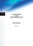
1
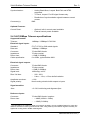
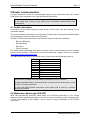
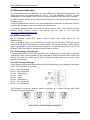
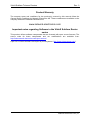
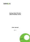
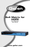
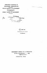
er
VikinX User Manual
SL-T6464(-CP)/SL-T3232(-CP)
SL-T1616(-CP)/SL-T0808(-CP)
Telecom Routers
in the
VikinX Sublime series
network-electronics.com
Rev. 0
VikinX Sublime Telecom Routers
Rev. 0
Network Electronics AS
Nordre Kullerød 1
P.O. Box 1020
N-3204 Sandefjord, Norway
Phone: +47 33 48 99 99
Fax: +47 33 48 99 98
Email: [email protected]
www.network-electronics.com
Support Phone: +47 90 60 99 99
Revision history
Current revision of this document is the uppermost in the table below.
Rev.
Repl.
Date
Sign
0
-
2008-06-20
NBS
Change description
First release, based on SD/HD manual Rev.12.
network-electronics.com | 2
VikinX Sublime Telecom Routers
Rev. 0
Contents
Revision history .......................................................................................................... 2
1 Product overview ..................................................................................................... 4
1.1 Product versions.................................................................................................................4
2 Specifications .......................................................................................................... 6
2.1 Mechanics ..........................................................................................................................6
2.2 Power Supply .....................................................................................................................6
2.2.1 Power Alarm GPI.............................................................................................................6
2.3 Control................................................................................................................................6
2.4 140/155Mbps Telecom specifications ................................................................................7
2.5 34/45Mbps Telecom specifications ....................................................................................8
2.6 Connection details..............................................................................................................9
2.6.1 Power Supply pinout .......................................................................................................9
3 Configuration ......................................................................................................... 11
3.1 Router level ......................................................................................................................11
3.2 Router mode.....................................................................................................................11
3.3 Power alarm .....................................................................................................................11
3.3.1 Power alarm on GPI output ...........................................................................................11
3.4 Power-up mode / Extension enable .................................................................................12
3.5 Configuring output on Single bus panels..........................................................................12
4 LED status indication ............................................................................................. 13
4.1 Start-up.............................................................................................................................13
4.2 Alarm states .....................................................................................................................13
4.3 Ethernet states .................................................................................................................13
5 Router communication........................................................................................... 14
5.1 Serial connection..............................................................................................................14
5.2 Maximum cable length (RS-232)......................................................................................14
5.3 Ethernet connection .........................................................................................................15
5.4 NCB connection ...............................................................................................................15
5.4.1 Connecting control panels.............................................................................................15
5.4.2 Pin-out and cable type...................................................................................................15
5.4.3 Termination plug............................................................................................................16
5.4.4 Control bus structure .....................................................................................................16
5.4.5 Maximum distance between NCB devices ....................................................................16
6 Connecting signal cables to the Sublime router..................................................... 17
7 Control Panel operation ......................................................................................... 18
7.1 Button description.............................................................................................................18
General environmental requirements for Network Electronics equipment ................ 20
Product Warranty...................................................................................................... 21
Important notes regarding Software in the VikinX Sublime Router series ................ 21
Appendix A Materials declaration and Recycling information ................................... 22
A.1 Materials declaration........................................................................................................22
A.2 Recycling information.......................................................................................................22
EC Declaration of Conformity ................................................................................... 23
network-electronics.com | 3
VikinX Sublime Telecom Routers
Rev. 0
1 Product overview
Network Electronics are proud to present the 2nd generation of the compact small and
medium routing switcher family, Sublime. With Sublime, Network Electronics now provide a
stable and proven product line including the most complete signal format and size offering
available.
With the new ultra slim, multi format and flexible product range, Sublime fulfils the most
demanding requirements from the professional broadcast market.
This User Manual presents the features, installation and operation procedures of the
Telecom routers of the Sublime range.
− Meets ITU-T G.703 for CMI coded signals (140/155Mbps)
− Meets ITU-T G.703 for HDB3 coded signals (34/45Mbps)
− Router range from 8x8 to 64x64
− Software based Configurator for easy system set-up
− TCP/IP, RS-232 and NCB Control (RJ-45)
− Programmable multi- single- and dual bus control panels
− Ultra Slim frame depth
− Low Power, high reliability design
− Redundant power supply system with front indicators
− Interoperability with existing VikinX routers
− Future proof and flexible product range
VikinX Sublime provides many of the powerful control features that drove the VikinX Modular
range to success. VikinX Sublime is ideal for general purpose facilities, on-air routing, mobile
outside broadcast applications and sophisticated A/V applications.
1.1 Product versions
The following versions of the VikinX Sublime 140/155Mbps Telecom routers are available:
140/155Mbps Telecom – 19” - 1RU, depth 5cm:
SL-T0808 /
SL-T0808-CP
SL-T1616 /
SL-T1616-CP
8x8 Telecom Router (140/155Mbps). Ethernet/RS-232/NCB
control, router partitioning, programmable X-Y control panel (on
CP version)
16x16 Telecom Router (140/155Mbps). Ethernet/RS-232/NCB
control, router partitioning, programmable X-Y control panel (on
CP version)
140/155Mbps Telecom – 19” - 2RU, depth 5cm:
SL-T3232 /
SL-T3232-CP
32x32 Telecom Router (140/155Mbps). Ethernet/RS-232/NCB
control, router partitioning, programmable X-Y control panel (on
CP version)
140/155Mbps Telecom – 19” - 4RU, depth 5cm:
SL-T6464 /
SL-T6464-CP
64x64 Telecom Router (140/155Mbps). Ethernet/RS-232/NCB
control, router partitioning, programmable X-Y control panel (on
CP version)
By combining VikinX Sublime Analog Video routers with VikinX Compact 34/45Mbps
reclocking units (RECL-8), the following 34/45Mbps telecom routers are available:
network-electronics.com | 4
VikinX Sublime Telecom Routers
Rev. 0
34/45Mbps Telecom – 19” - 2RU, depth 5cm:
SL-V0808 /
SL-V0808-CP +
1x RECL-8
8x8 Telecom Router (34/45Mbps). Ethernet/RS-232/NCB control,
router partitioning, programmable X-Y control panel (on CP
version)
34/45Mbps Telecom – 19” - 3RU, depth 5cm:
SL-V1616 /
SL-V1616-CP +
2x RECL-8
16x16 Telecom Router (34/45Mbps). Ethernet/RS-232/NCB
control, router partitioning, programmable X-Y control panel (on
CP version)
34/45Mbps Telecom – 19” - 6RU, depth 5cm:
SL-V3232 /
SL-V3232-CP +
4x RECL-8
32x32 Telecom Router (34/45Mbps). Ethernet/RS-232/NCB
control, router partitioning, programmable X-Y control panel (on
CP version)
34/45Mbps Telecom – 19” - 12RU, depth 5cm:
SL-V6464 /
SL-V6464-CP +
8x RECL-8
64x64 Telecom Router (34/45Mbps). Ethernet/RS-232/NCB
control, router partitioning, programmable X-Y control panel (on
CP version)
Available Control Panels – 19” – 1RU:
SL-16XY-CP
SL-8XY-CP
SL-16D-CP
SL-32S-CP
SL-32S-CP-GPI
SL-16S-CP
SL-16S-CP-GPI
SL-8S-CP
SL-8S-CP-GPI
SL-16XY-CP
Multi bus X-Y 16x16 panel.
Multi bus X-Y 8x8 panel.
Dual bus 16x2 panel.
Single bus 32x1 panel.
Single bus 32x1 panel with GPI / Joystick / Tally interface.
Single bus 16x1 panel.
Single bus 16x1 panel with GPI / Joystick / Tally interface.
Single bus 8x1 panel.
Single bus 8x1 panel with GPI / Joystick / Tally interface.
Multi bus X-Y 16x16 panel.
Available Control Panels – 19” – 2RU:
SL-32XY-CP
SL-64S-CP
SL-64S-CP-GPI
Multi bus X-Y 32x32 panel.
Single bus 64x1 panel.
Single bus 64x1 panel with GPI / Joystick / Tally interface.
Available Control Panels – 19” – 4RU:
SL-64XY-CP
Multi bus X-Y 64x64 panel.
network-electronics.com | 5
VikinX Sublime Telecom Routers
Rev. 0
2 Specifications
2.1 Mechanics
Router dimensions:
−
−
−
Safety/Emission
standards:
Compliant with CE EN55103-1 and 2.
HxWxD = 44x483x50mm, (19”, 1RU);
HxWxD = 88x483x50mm, (19”, 2RU);
HxWxD = 176x483x50mm, (19”, 4RU).
2.2 Power Supply
SL-PWR-90
90W Power Supply Unit for SL-V6464(-CP).
SL-PWR-40
DP AC +/-5V/35W
AC Supply voltage range:
40W Power Supply Unit for all other routers.
35W Power Supply Unit for RECL-8 unit(s).
100-240VAC, 50-60Hz,
− Max 1.6A (SL-PWR-40) / Max 3A (SL-PWR-90);
− Max 1.6A (DP AC +/-5V/35W).
AC Mains connector:
DC output:
IEC 320.
− +15V, max. 4A / -15V, max 2.5A. Maximum 90W for
SL-V6464(-CP);
− +15V, max. 2.2A / -15V, max 1.35A. Maximum 43W for all
other routers;
− +5.3V, max 5A / -5.3V, max 3.5A. Maximum 35W for
RECL-8.
DC connector:
Status monitoring:
DB9, female.
− Via LED in front of the router/CP,
− Via GPI for monitoring by 3rd party.
2.2.1 Power Alarm GPI 1
Connector:
Signal type:
Maximum voltage:
Maximum current:
DB9, female.
Open collector transistor.
30 V
100 mA
2.3 Control
Standard Features:
Serial port:
Connector:
NCB ports:
Connectors (2):
Ethernet port:
Connector:
1
RS-232 for protocol conversion, to VikinX compact control
protocol, or to third party protocols.
DB9, female.
For integration with VikinX compact router configuration.
RJ45 (1 In / 1 Out).
10/100BaseT Ethernet bus for external router control.
RJ45.
Not applicable on the RECL-8 unit; only on Sublime routers and control panels.
network-electronics.com | 6
VikinX Sublime Telecom Routers
Synchronization 2 :
−
−
−
Connector(s):
Rev. 0
Analog Black Burst, Looped. Both PAL and NTSC
supported.
Tri-Level, Looped. For HD signal formats only.
Distribution of synchronization signals between several
routers.
BNC.
Optional Features:
Control Panel:
−
−
Optional, built-in control panel available.
External control panels available.
2.4 140/155Mbps Telecom specifications
Supported formats:
Telecom:
140Mbps / 155Mbps G.703 CMI.
Electrical signal inputs:
Standard:
Data rate:
Connector:
Impedance:
Return loss:
Cable equalization:
ITU-T G.703 for CMI coded signals.
140Mbps / 155Mbps.
75 ohm BNC female.
75 ohm nominal.
> 15dB (5-540Mhz).
0 to 250m, typical Belden 8281.
Electrical signal outputs:
Connector:
Impedance:
Return loss:
Signal level:
Rise / fall time:
75 ohm BNC female.
75 ohm nominal.
> 15dB (5-540Mhz).
1000mVp-p ±10%.
− 20% - 80%
− 0.4ns – 1.5ns, < 0.5ns rise/fall variation.
Amplitude overshoot:
Signal polarity:
< 10%.
Non-inverting electrical with respect to inputs.
Signal transition:
Jitter:
< 0.2 UI, both timing and alignment jitter.
Reference inputs:
Connector:
Return loss:
75 ohm BNC female, loop-thru.
− > 40dB (100kHz – 5Mhz)
− > 35dB (5-10MHz).
2
Synchronization of a telecom router is not strictly necessary, but an available feature for users who
intend to switch this router synchronized to video, using video synchronization signals. Normally not
applied for routing CMI or HDB3 coded signals.
network-electronics.com | 7
VikinX Sublime Telecom Routers
Signal format:
Signal level:
Switching Field:
Timing:
Rev. 0
NTSC or PAL Black Burst.
Nominal 1.0Vp-p.
Field 1.
− PAL: within clock-intervals (27MHz) 565 – 835 in line 6
− NTSC: within clock-intervals (27MHz) 565 – 835 in line 10.
2.5 34/45Mbps Telecom specifications
Supported formats:
Telecom:
34Mbps / 45Mbps G.703 HDB3.
Electrical signal specifications:
Frequency response:
Return loss:
Output DC offset error:
Gain:
Crosstalk:
Differential gain:
Differential phase:
Bar tilt:
Lum. Non-linearity:
Video S/N:
Max. signal level:
Delay difference, any
input to one output:
Connector:
Impedance:
100kHz – 5MHz: +0/-0.1dB
100kHz – 30MHz: ±0.5dB
0Hz – 125MHZ: +0.5/-3dB.
> 40dB @5.5MHz, 75 ohm BNC
> 35dB @10MHz.
< 15mV DC.
0dB ±0.1dB.
< -60dB up to 5MHz.
< 0.1%, for routers up to 16x16;
< 0.2%, for 32x32 and 64x64 routers.
< 0.1º, for routers up to 16x16;
< 0.2º, for 32x32 and 64x64 routers.
< 0.1%.
< 0.1%, for routers up to 16x16;
< 0.2%, for 32x32 and 64x64 routers.
> 70dB, unweighted
> 2Vpp.
< ±1nsec.
75 ohm BNC female.
75 ohm nominal.
For more details on RECL-8, see User Manual for this device here:
RECL8_user_manual.pdf
Reference inputs:
Connector:
Return loss:
Signal format:
Signal level:
Switching Field:
Timing:
75 ohm BNC female, loop-thru.
> 40dB (100kHz – 5Mhz)
> 35dB (5-10MHz).
NTSC or PAL Black Burst.
Nominal 1.0Vp-p.
Field 1.
− PAL: 30us ±5us after hsync in line 6
− NTSC: 30us ±5us after hsync in line 10.
network-electronics.com | 8
VikinX Sublime Telecom Routers
Rev. 0
2.6 Connection details
Available service connectors at the back panel of the Sublime Routers 3 :
−
−
−
−
−
−
−
−
−
SYNC: Synchronization signal (in). Black burst/composite/tri-level sync reference
input with passive loop-through for vertical interval switching.
LOOP: Synchronization signal (out). Loop-through of SYNC input.
NCB IN: Network Control Bus Input. The protocol of this bus is equal, and compatible
to the MIDI bus protocol.
NCB OUT: Network Control Bus Output.
ETHERNET: 10/100Base-T Ethernet bus for external router control.
RS 232: RS-232 for external control protocols.
POWER A: ±15VDC Power Input.
POWER B: ±15VDC Power Input, redundant supply.
CONFIGURATION: Configuration switches (8 pcs).
2.6.1 Power Supply pinout
The DB9 power pinout for Sublime routers and Control Panels are as follows;
Pin #
1
2
3
4
5
6
7
8
9
Description
GND
Not connected
Power Alarm GPI output
+15VDC
Not connected
Not connected
Not connected
-15VDC
Not connected
Please see Chapter 2.2.1 and Chapter 3.3 for further description of the GPI output (Pin #3).
3
Note that the picture shows a 1RU Sublime router. However, the service connectors are identical to
the above also on the 2RU and 4RU units. The only connectors that differ are the applicable signal
connectors.
network-electronics.com | 9
VikinX Sublime Telecom Routers
Rev. 0
The DB9 power pinout for RECL-8 is as follows;
Pin #
1
2
3
4
5
6
7
8
9
Description
GND
+5VDC
Not connected
Not connected
Not connected
-5VDC
Not connected
Not connected
Not connected
network-electronics.com | 10
VikinX Sublime Telecom Routers
Rev. 0
3 Configuration
In order to get an overview of the parts that form the Sublime Telecom Routers this chapter
will highlight some of the main components.
3.1 Router level
Switches 1 - 4 on the configuration switch set the router’s level for communication with the
Router Management System and other units in the NCB system. The panels on the NCB
dedicated to operate with the router must be configured to the same level as that router.
If several routers are combined to form an Audio Follow Video, RGB or similar system, these
routers must be configured to the same level.
The levels can be switched according to the following pattern:
SW 1
OFF
OFF
OFF
OFF
OFF
OFF
OFF
OFF
ON
ON
ON
ON
ON
ON
ON
ON
SW 2
OFF
OFF
OFF
OFF
ON
ON
ON
ON
OFF
OFF
OFF
OFF
ON
ON
ON
ON
SW 3
OFF
OFF
ON
ON
OFF
OFF
ON
ON
OFF
OFF
ON
ON
OFF
OFF
ON
ON
SW 4
OFF
ON
OFF
ON
OFF
ON
OFF
ON
OFF
ON
OFF
ON
OFF
ON
OFF
ON
Level
1
2
3
4
5
6
7
8
9
10
11
12
13
14
15
16
NCB Address
0
1
2
3
4
5
6
7
8
9
10
11
12
13
14
15
Default level is 1.
3.2 Router mode
The router mode function is not in use on Sublime Telecom routers. Switches 5 – 6 on the
configuration switch must always be in position OFF.
3.3 Power alarm
The power alarm can be switched according to the following pattern:
SW 7
OFF
ON
Power alarm
Disables Power Alarm
Enables Power Alarm
Default setting is Power Alarm disabled.
3.3.1 Power alarm on GPI output
The SL-PWR-40/SL-PWR-90 has a GPI output for alarm. This alarm is an open collector
from pin 3 to GND (Pin 1) on the PSU connector. Hint: Use a standard Y-cable and wire the
“free” connector to the automation system.
network-electronics.com | 11
VikinX Sublime Telecom Routers
Rev. 0
Pin 3 and GND (Pin 1) are closed contact as long as the power is OK; when the power is
failing it will become open. The GPI output can switch a maximum load of 100mA at 30V.
Any device to be controlled by the GPI outputs (lamp, LED or similar) needs to be connected
to an external supply voltage on one end and to the GPI output on the other end.
3.4 Power-up mode / Extension enable
Switch 8 on the configuration switch defines the power up mode on NxN square routers. The
Sublime router provides two modes for powering up the system.
The power up options can be switched according to the following pattern:
SW 8
OFF
ON
Power Up mode
Switches all outputs according to the
buffered information in the routers
processor system.
Switches all outputs to input 1.
Default setting switches all outputs according to the buffered information in the routers
processor system.
3.5 Configuring output on Single bus panels
See Chapter 7.1, section Input for configuring default output to be controlled from a Single
bus control panel.
network-electronics.com | 12
VikinX Sublime Telecom Routers
Rev. 0
4 LED status indication
4.1 Start-up
The LED located at the front of the router indicates the status of the router. At start-up, the
LED will alternate between red (R) and green (G) every 500ms for about two seconds. After
the start-up sequence the LED will indicate the Alarm state of the router.
There are two LEDs located at the Ethernet bus. At start-up the boot loader is searching for
update commands on the serial port for about two seconds. During this sequence both
Ethernet LEDs will be blinking. After the start-up sequence the LEDs will indicate the
Ethernet state.
4.2 Alarm states
The LED can either be red (R), green (G), yellow (Y) or have no light (N).
The LED state is here described with twenty letters, each representing 100ms, which totals
to an alarm sequence of two seconds. The X indicates that the LED keeps the color it has
the moment the alarm sequence begins (green, yellow or no light).
Description
Continuous
green light
Continuous
yellow light
Long red
blinks
One short
red blink
Two short
red blinks
LED state
GGGGG GGGGG GGGGG
GGGGG
YYYYY YYYYY YYYYY YYYYY
RRRRR NNNNN RRRRR NNNNN
RXXXX XXXXX XXXXX XXXXX
XXXXX XXXXX RXRXX XXXXX
Alarm
No alarm.
Status is OK.
Unable to
connect to
controller over
Ethernet.
Power is too
low.
Power A
failed
Power B
failed
Comment
This alarm will be
overwritten by other
alarms
Only active if power
alarm dip is set.
Only active if power
alarm dip is set.
4.3 Ethernet states
The LEDs that are located at the Ethernet bus will after the Start-up sequence indicate the
Ethernet states:
Green
Yellow
On
Valid link
No data
Off / Blinking
No link
Data is transmitted or received
network-electronics.com | 13
VikinX Sublime Telecom Routers
Rev. 0
5 Router communication
You gain access to router for communication purposes by connecting either the router’s
serial port to your computer or by using an Ethernet connection.
Do not use both the router’s Ethernet port and RS-232 serial port, or NCB ports,
at the same time. Doing so may cause loss of important communication and
control data.
5.1 Serial connection
Connection can by made trough the serial port(s) of the router; see also Chapter 2.6 for
connection details.
The communication parameters are configurable. Please refer to the protocol documentation
of the appropriate communication/control protocol.
Example: The protocol parameters of the VikinX Compact routers are as follows:
− Bit rate 19200 bit/s
− Data bits 8 bits
− Stop bits 1
− Parity: No parity
For further detail concerning this protocol, please refer to the following manual: Compact
Router Control Protocol. This manual can be found under the “Support” tab on our web site:
http://www.network-electronics.com.
The DB9 female connector for the serial port(s) of the router has the following pin-out:
Pin #
1
2
3
4
5
6
7
8
9
RS-232 mode
Not in use
Tx
Rx
Not in use
GND
GND
RTS
CTS
Do Not Connect!
Note that if the standard RS-232 cable specification (DCE) is followed:
A cable with Male+Male or Female+Female connectors at the cable ends is used
for Rx/Tx crossed connection.
A cable with Male+Female connectors at the cable ends is used for a straight
through connection.
5.2 Maximum cable length (RS-232)
IEEE has specified the maximum cable length for an RS-232 connection to 15m. Longer
distances can be installed depending on the environmental conditions of the installation site.
It is the responsibility of the installer / user to secure a proper installation of the RS-232
connection.
network-electronics.com | 14
VikinX Sublime Telecom Routers
Rev. 0
5.3 Ethernet connection
The connections follow the standard set by the IEEE 802.3 100BaseTX specification. The
cables that are to be applied should be CAT-5 / CAT-5E standard, or better. It is the
responsibility of the installer / user to secure a proper installation of the Ethernet connection.
All VikinX Sublime routers and IP-based Control Panels are connected together through an
Ethernet Switch.
A VikinX Sublime device can only have one open Ethernet connection. If redundant control is
required, this limitation has to be solved by the control system.
For Ethernet protocol details concerning this router, please refer to the following manual:
Modular Router Control Protocol. This manual can be found on our web site:
http://www.network-electronics.com.
5.4 NCB connection
Via the Network Control Bus system several routers and control panels can be
interconnected.
Up to 16 levels of routers, or combinations of routers, can be controlled. The NCB system
and all RS 232 ports interchange the system status. This means that any control system,
either from Network, or from a third party manufacturer, connected to any RS 232 port in the
NCB loop, will have access to all communication data on the bus.
5.4.1 Connecting control panels
To get a control panel working with a specific router, configure the control panel to the same
level as the router. Several panels can be configured to control the same router. Panels can
also be connected to a router via the RS-232 interface. Please refer to your control panel
manual for installation.
5.4.2 Pin-out and cable type
VikinX Sublime routers and Control Panels use RJ45 connectors for the Network Control Bus
ports. The following pin-out is used:
Pin #1
Pin #2
Pin #3
Pin #4
Pin #5
Pin #6
Pin #7
Pin #8
Not Connected
Not Connected
Data (retour)
Data
Data
Data (retour)
Not Connected
Not Connected
The following connection example shows connection of 4 VikinX devices with RJ45
connectors and bus termination:
Four devices connected together using RJ45
network-electronics.com | 15
VikinX Sublime Telecom Routers
Rev. 0
Note that each device at the end of the chain has a termination plug, indicated with the letter
“T”. This termination plug must be inserted in the correct connection port. If not, no NCB
communication is possible.
5.4.3 Termination plug
The termination plug that is mentioned in the previous chapter is necessary when you want
to avoid closing the loop be a (long) cable.
The termination plug is a standard RJ45 plug with the following internal wiring:
RJ45 Termination plug
As seen in the figure above, Pin 3 is connected to Pin 4, and Pin 5 is connected to Pin 6.
5.4.4 Control bus structure
The Network Control Bus structure follows the standard MIDI bus definition. The NCB is
defined as a closed chain of units. This means that the NCB OUT of the last unit must be
connected to the NCB IN of the first unit in the NCB chain. To avoid problems with the control
of VikinX units the installer/user has to assure that the bus structure is installed according to
this definition.
The total number of VikinX devices in an NCB chain is limited to 50.
5.4.5 Maximum distance between NCB devices
The standard MIDI definition allows a maximum cable length of 200-250 meters between two
devices. Longer distances can be made with MIDI repeater units. To avoid grounding
problems all NCB ports have opto-coupled inputs.
network-electronics.com | 16
VikinX Sublime Telecom Routers
Rev. 0
6 Connecting signal cables to the Sublime router
The Sublime Telecom Router offers standard 75Ohms BNC connectors for video in- and
outputs. All video inputs are terminated with 75Ohms.
network-electronics.com | 17
VikinX Sublime Telecom Routers
Rev. 0
7 Control Panel operation
This chapter is only applicable for routers with the optional local control panel.
All local control panels are completely configurable with the System Configurator, which is
downloadable from the Support pages at http://www.network-electronics.com/
All local control panels are given a default configuration, which includes the buttons “A/V
Toggle”, “Panel Enable”, “Take on/off” and “Take”. In addition input and output buttons are
preconfigured.
7.1 Button description
A/V Toggle
The A/V Toggle button enables/disables audio and video on a specified address. The
address can either be read from the dip switches, or be fixed. The button toggles between
three states.
If the button is pressed for more than 1 second, it will go into a fourth state where
both audio and video are disabled.
In this state the button will be dimmed. If the button is pressed for more than 1 second again,
it will enable both audio and video if present.
Button Color
Video Enabled
Audio Enabled
Yes
Yes
Yellow
Yes
No
Green
No
Yes
Red
No
No
Dimmed
If neither audio nor video is present, it will be marked as disabled and the toggle state will not
be used.
Toggle status changes will be stored in flash and used when the panel is powered up later.
Panel Enable
If a Panel Enable button is present, the panel will start up not enabled. In this state the button
will be red and all the other buttons will be disabled. When pressing the button the panel will
be enabled and the color will change to green. A status request will also be sent to get
information on active levels.
If no Panel Enable button is present, the panel will start up enabled.
Take on/off
The Take on/off button enables or disables the Take button. If no take button is defined,
Take on/off is always off. On first start-up the take button is enabled. Later it will read the last
status from the flash memory.
Take
The Take buttons LED is normally off. If the Take on/off button is set to “on”, no commands
will be sent from the panel until the Take button is pressed. The last selected buttons and the
take button will blink, until the Take button is pressed and the command is sent from the
panel.
network-electronics.com | 18
VikinX Sublime Telecom Routers
Rev. 0
Output
An Output button is used for selecting an output. Selecting an output activates it, so that it is
switched to the next input that is selected.
Input
An Input button switches the active output to the selected input. If the Take button is enabled,
the switch will not be executed until the Take button is pressed.
When switching using the Input button, all enabled audio- and video-levels will be switched
from the selected input to the active output.
The Input button can also be used to select the active output. This is useful on
single bus panels. It requires that a Panel Enable button is present. When the
panel is enabled, press the Panel Enable button and hold it while selecting the
active output by pressing an Input button. Then release the Panel Enable button.
The panel will now be disabled. Press the Panel Enable button again to enable it.
XY
An Input to Output (XY) button switches a preset input to a preset output on all enabled
audio- and video-levels. If the Take button is enabled, the switch will not be executed until
the Take button is pressed.
Salvo
A Salvo button switches a sequence of cross points. This is done even if the specified audioor video-level is disabled.
Lock
A Lock Toggle button toggles the lock-status on the active output on all enabled audio- and
video-levels. If the active output on any of the enabled levels is locked before pressing the
button, they will be unlocked. If not the active output on all enabled levels will be locked. A
locked output can’t be switched.
network-electronics.com | 19
VikinX Sublime Telecom Routers
Rev. 0
General environmental requirements for Network Electronics
equipment
1.
2.
-
The equipment will meet the guaranteed performance specification under the following
environmental conditions:
Operating room temperature range: 0°C to 45°C
Operating relative humidity range:
<95% (non-condensing)
The equipment will operate without damage under the following environmental
conditions:
Temperature range:
-10°C to 55°C
Relative humidity range:
<95% (non-condensing)
network-electronics.com | 20
VikinX Sublime Telecom Routers
Rev. 0
Product Warranty
The warranty terms and conditions for the product(s) covered by this manual follow the
General Sales Conditions by Network Electronics AS. These conditions are available on the
company web site of Network Electronics AS:
www.network-electronics.com
Important notes regarding Software in the VikinX Sublime Router
series
This product utilizes software components that are licensed with open source licenses. The
source code for these components and our modifications are available from:
http://labs.network-electronics.com/open-source/.
OpenTCP includes software developed by Viola systems (http://www.violasystems.com/).
network-electronics.com | 21
VikinX Sublime Telecom Routers
Rev. 0
Appendix A Materials declaration and Recycling
information
A.1 Materials declaration
For product sold into China after 1st March 2007, we comply with the “Administrative
Measure on the Control of Pollution by Electronic Information Products”. In the first stage of
this legislation, content of six hazardous materials has to be declared. The table below
shows the required information.
Toxic or hazardous substances and elements
組成名稱
Part Name
鉛
汞
镉
六价铬
多溴联苯
多溴二苯醚
Lead Mercury Cadmium Hexavalent Polybrominated Polybrominated
(Pb)
(Hg)
(Cd)
Chromium
biphenyls
diphenyl ethers
(Cr(VI))
(PBB)
(PBDE)
All products
referred to in
Chapter 1.1
O
O
O
O
O
O
SL-PWR-40
O
O
O
O
O
O
SL-PWR-90
O
O
O
O
O
O
DP AC +/-5V/35W
O
O
O
O
O
O
O: Indicates that this toxic or hazardous substance contained in all of the homogeneous
materials for this part is below the limit requirement in SJ/T11363-2006.
X: Indicates that this toxic or hazardous substance contained in at least one of the
homogeneous materials used for this part is above the limit requirement in SJ/T11363-2006.
This is indicated by the product marking:
A.2 Recycling information
Network Electronics AS provides assistance to customers and recyclers through our web site
http://www.network-electronics.com. Please contact Network Electronics AS’s Customer
Support for assistance with recycling if this site does not show the information you require.
Where it is not possible to return the product to Network Electronics AS or its agents for
recycling, the following general information may be of assistance:
−
−
−
−
Before attempting disassembly, ensure the product is completely disconnected from
power and signal connections.
All major parts are marked or labeled to show their material content.
Depending on the date of manufacture, this product may contain lead in solder.
Some circuit boards may contain battery-backed memory devices.
network-electronics.com | 22
VikinX Sublime Telecom Routers
Rev. 0
EC Declaration of Conformity
MANUFACTURER
Network Electronics AS
P.B. 1020, N-3204 SANDEFJORD, Norway
AUTHORISED REPRESENTATIVE
(Established within the EEA)
MODEL NUMBER(S)
Not applicable
SL-T0808
SL-T0808-CP
SL-T1602
SL-T1602-CP
SL-T1616
SL-T1616-CP
DESCRIPTION
Telecom Routers in the VikinX Sublime series
DIRECTIVES this equipment complies with
LVD 73/23/EEC
EMC 2004/108/EEC
HARMONISED STANDARDS applied in order to
verify compliance with Directive(s)
EN 55103-1:1996
EN 55103-2:1996
EN 60950-1:2006
TEST REPORTS ISSUED BY
Notified/Competent Body
Report no:
Nemko
E08443.00
TECHNICAL CONSTRUCTION FILE NO
Not applicable
YEAR WHICH THE CE-MARK WAS AFFIXED
2008
TEST AUTHORIZED SIGNATORY
MANUFACTURER
AUTHORISED REPRESENTATIVE
(Established within EEA)
Date of Issue
2008-01-31
Place of Issue
Not applicable
Name
Thomas Øhrbom
Position
Quality Manager
(authorized signature)
Sandefjord, Norway
network-electronics.com | 23