1
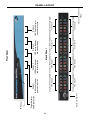
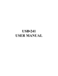
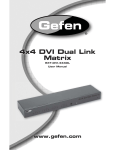
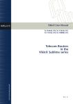
4x4 Component
w/Audio Matrix
EXT-COMPAUD-44424
User Manual
www.gefen.com
f
ASKING FOR ASSISTANCE
Technical Support:
Telephone
Fax
(818) 772-9100
(800) 545-6900
(818) 772-9120
Technical Support Hours:
8:00 AM to 5:00 PM Monday thru Friday.
Write To:
Gefen Inc.
c/o Customer Service
20600 Nordhoff St
Chatsworth, CA 91311
www.gefen.com
[email protected]
Notice
Gefen Inc. reserves the right to make changes in the hardware, packaging and
any accompanying documentation without prior written notice.
4x4 Component w/Audio Matrix is a trademark of Gefen Inc.
© 2008 Gefen Inc., All Rights Reserved
All trademarks are the property of their respective companies
CONTENTS
1
Introduction
2
Operation Notes
3
Features
4
Panel Layout
5
Connecting And Operating The 4x4 Component w/Audio Matrix
6
RMT-16-IR Remote Installation
7
RS-232 Serial Control Interface
8
Rack Mount Installation
9
Specifications
10 Warranty
INTRODUCTION
Congratulations on your purchase of the 4x4 Component w/Audio Matrix. Your
complete satisfaction is very important to us.
Gefen
Gefen delivers innovative, progressive computer and electronics add-on solutions
that harness integration, extension, distribution and conversion technologies.
Gefen’s reliable, plug-and-play products supplement cross-platform computer
systems, professional audio/video environments and HDTV systems of all sizes
with hard-working solutions that are easy to implement and simple to operate.
The Gefen 4x4 Component w/Audio Matrix
The Gefen 4x4 Component w/Audio Matrix offers unprecedented flexibility and
convenience by routing high definition video and analog/digital audio from any of
four sources to any of 4 local displays and audio reproduction equipment.
Full High-Resolution HDTV signals are supported up to a resolution of 1080p.
The Gefen 4x4 Component w/Audio Matrix works with any Component Video
source including DVD players, cable boxes, and satellite set-top boxes that
connect to a Component display. Every source is accessible at all times by any
display by selecting it with the IR remote.
How It Works
Connect up to 4 local Component AV sources to the Matrix’s inputs. Connect the
outputs to up to 4 Component displays and audio receivers, plug in the power
supply, and crisp, vibrant video with audio will appear at the chosen locations.
1
OPERATION NOTES
READ THESE NOTES BEFORE INSTALLING OR
OPERATING THE 4X4 COMPONENT W/AUDIO MATRIX
•
The 4x4 Component Audio Matrix is housed in a metal box for better RF
shielding.
•
The 4x4 Component Audio Matrix works with all component displays.
2
FEATURES
Features
•
Switches easily between any four component/audio sources
•
Sends up to four video inputs to any four remote displays
•
Maintains 1080p, and 2k resolution video
•
Discrete IR remote (included)
•
Serial RS-232 remote port (for unattended control)
•
Rack ears included
•
Specifications:
Package Includes
(1) 4x4 Component w/Audio Matrix
(4) 6-foot 5 RCA Component Audio/Video cables
(1) 24V DC Power Supply
(1) Rack Ears
(1) User’s Manual
3
RS232 Controller Port
Power Indicator
and Reset button
IR Sensor
4
Display 3
LED source Indicator
and selector button
Back Panel
Display 2
LED Source Indicator
and selector button
Display 4
LED Source Indicator
and selector button
Connects to 12VDC Power
Supply
Component and Analog/Digital Component and Analog/Digital Component and Analog/Digital Component and Analog/Digital
Audio Output 4
Audio Output 2
Audio Input 4
Audio Input 2
Component and Analog/Digital Component and Analog/Digital Component and Analog/Digital Component and Analog/Digital
Audio Output 3
Audio Output 1
Audio input 3
Audio Input 1
Display 1
LED Source Indicator
and selector button
Front Panel
PANEL LAYOUT
CONNECTING AND OPERATING THE 4X4 COMPONENT W/AUDIO MATRIX
How to Connect the 4x4 Component w/Audio Matrix
1.
Connect up to 4 component video/audio sources to the 4x4 Component w/
Audio Matrix inputs using the supplied 5 RCA analog stereo audio cable
Optionally, connect digital coaxial audio to the 4x4 Component w/Audio
Matrix using a user supplied digital coaxial cable.
2.
Connect up to 4 component video displays to the 4x4 Component w/Audio
Matrix outputs using user supplied component cables.
3.
Connect analog/digital audio outputs on the 4x4 Component w/Audio Matrix
to either the component displays or a separate audio receiver.
4.
Connect the included 24V DC power supply to the 4x4 Component w/Audio
Matrix.
How to Connect the 4x4 Component w/Audio Matrix
Routing of video to displays is done using either the included RMT-16-IR
remote control or the direct select buttons located on the front panel of the 4x4
Component w/Audio Matrix.
Using the RMT-16-IR remote control
The RMT-16-IR remote control uses 16 buttons to select 1 of 4 sources for each
display to view. Each output display has a grouping of 4 buttons allocated for
selecting each source. Use the chart below to route video to your desired display.
RMT-16-IR
Button
Display
Source
RMT-16-IR
Button
Display
Source
1
1
1
9
3
1
2
1
2
10
3
2
3
1
3
11
3
3
4
1
4
12
3
4
5
2
1
13
4
1
6
2
2
14
4
2
7
2
3
15
4
3
8
2
4
16
4
4
Using the Direct Source Buttons
Each display output on the 4x4 Component w/Audio Matrix has a push-button
located on the front panel. Pressing this button will cycle through the 4 source
inputs. Press the button for each display repeatedly to select the desired source
for viewing on that display.
5
RMT-16-IR REMOTE INSTALLATION
1.
Remove battery cover from the back of the RMT-16-IR remote.
2.
Verify that dip switches 1 & 2 are in the down (OFF) position.
3.
Insert the battery, hold the battery so that you can see the positive side facing
up. The side that is not marked must be facing down.
4.
Test the RMT-16-IR remote by pressing ONLY one button at a time. The
indicator light on the remote will flash once each time you press a button.
WARNING: Do not press multiple buttons simultaneously and do NOT press buttons
rapidly. These actions will cause the remote to reset and steps 1-4 will have to be
repeated.
NOTE: The RMT-16-IR ships with two batteries. One battery is required for
operation, the second battery is complimentary.
6
RS-232 SERIAL CONTROL INTERFACE
12345
12345
6789
6789
Only Pins 2 (RX), 3 (TX), and 5 (Ground) are used on the RS-232 serial interface
Binary Table
ASCII Corresponding
RMT16-IR
Button
1
1
2
2
3
3
4
4
5
5
6
6
7
7
8
8
Binary
ASCII
0011 0001
0011 0010
0011 0011
0011 0100
0011 0101
0011 0110
0011 0111
0011 1000
9
a
b
c
d
e
f
g
Corresponding
RMT16-IR
Button
9
10
11
12
13
14
15
16
Binary
0011 1001
0110 0001
0110 0010
0110 0011
0110 0100
0110 0101
0110 0110
0110 0111
RS232 Settings
Bits per second ................................................................................................. 19200
Data bits .................................................................................................................... 8
Parity .................................................................................................................. None
Stop bits .....................................................................................................................1
Flow Control ....................................................................................................... None
7
RACK MOUNT INSTALLATION
Rack mount ears are provided for installation of this unit into a 1U rack mount
space.
1.
2.
3.
4.
Locate the side screws on the unit.
Remove the front 2 screws that are located closest to the front of the unit.
Using the removed screws, screw the rack mounting bracket into the unit.
Repeat the procedure on the opposite side of the unit.
1
Front of unit
Rear of unit
2
3
4
8
SPECIFICATIONS
Video Amplifier Bandwidth ....................................................................... 350 MHz
Input Video Signal .............................................................................. 1.2 Volts p-p
Video Resolution .......................................................................................... 1080p
Video Connector ...................................................................... RCA-style RGB x 3
Analog Audio Connector ................................................. RCA-style L + R (Stereo)
Digital Audio Connector .......................................................... S/PDIF Coax. in/out
Remote Control Port ........................................................................ RS232 female
Power Supply Sender .............................................................. 24V DC (60 Watts)
Dimensions ....................................................................... 17”W x 3.5”H x 5.875”D
Shipping Weight ............................................................................................ 8 lbs.
9