1
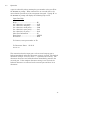
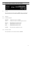
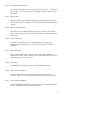
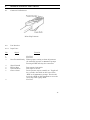
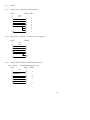
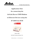
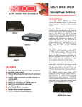
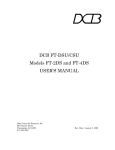
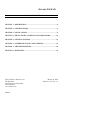
Access Switch
TABLE OF CONTENTS
SECTION 1 - DESCRIPTION....................................................................... 2
SECTION 2 - SPECIFICATIONS ................................................................. 4
SECTION 3 - INSTALLATION..................................................................... 6
SECTION 4 - FRONT PANEL CONTROLS AND INDICATORS.............. 13
SECTION 5 - SETUP FUNCTIONS ........................................................... 14
SECTION 6 - INTERFACE SIGNALS AND CABLING.............................. 18
SECTION 7 - TROUBLESHOOTING......................................................... 22
SECTION 8 - WARRANTY......................................................................... 23
Data Comm for Business, Inc.
PO Box 6329
Champaign, IL 61826-6329
(217) 897-6600
www.dcbnet.com
8500023
March 30, 2006
Firmware Version: 7.7
1.
DESCRIPTION
The DCB Access Switch is an ASCII character controlled switch used to
connect a maximum of six RS-232 asynchronous control devices to a
maximum of 152 asynchronous output ports. Connection is made by
entering a port number or port name. Disconnection is accomplished by
entering a disconnect code string or by lowering an RS-232 control lead.
Either the port being controlled or the originating port can lower a
control lead to force a disconnect.
The DCB Access Switch can be used to access any asynchronous device
from a terminal or PC. The Access Switch is specifically designed to
provide access to Network Management Ports on DCB equipment either
locally or via dial-up modems from a remote location.
The Access Switch is available in 4 thru 32 port models (AS-04, AS-08,
AS-16, AS-24 and AS-32) and an expandable AS-24M version. The AS04 thru AS-32 models have 2 input ports and 4, 8, 16, 24 or 32 output
ports, making them an ideal switch for smaller systems. The AS-24M
is a 24 channel master unit with 6 input ports and 24 output ports.
The AS-24M can be expanded by attaching up to four AS-32S slave
units. Each AS-32S has 32 ports, which increases the Access Switch
from 24 ports to 56, 88, 120 or 152 ports.
The Access Switch allows both local terminal and remote dial-in
access. All input ports can be active at the same time. The user
always gets positive feedback, there is no blind switching. Before
connect and after disconnect, the Access Switch gives the user an
Access >> (or user defined) prompt. Port switching requires no
cryptic code entry. Ports can be named and accessed by that name or
by port number.
If the device being accessed can be forced to lower an RS-232 control
lead on command, as is the case with DCB products, the hardware
disconnect method can be used. This makes the switch 100% data
transparent and suitable for use between devices that do binary file
transfers. Data transparency also insures that no control codes will
inadvertently cause a disconnect. Using hardware disconnect, a dial-in
modem can be used for remote computer support and for accessing the
communications equipment.
The Access Switch allows output ports to be defined as DATA, POWER
or DIALOUT. The default setting is DATA.
2
Ports defined as POWER ports are attached to the DCB APS-01 Access
Power Switch. Commands to the POWER ports allow the power to be
turned ON, turned OFF or CYCLED by the APS-01. The APS-01 will
switch up to a 15 amp 110 VAC load.
DIALOUT allows the output port to function as a normal DATA port,
while also allowing the attached device to dial out through the modem.
A typical application is a connection from the Access Switch to a
server, where connections are made to the server in DATA mode for
configuration and control of the server. The server uses the DIALOUT
mode to send paging messages to indicate server status.
For more information refer to Section 5, paragraphs 5.4.4 through
5.4.5.
Options:
• Internal 56K Dial-Up Modem (Not available on AS-24M)
• Ethernet port for LAN access (Not available on AS-4 or AS-24M)
3
2.
SPECIFICATIONS
2.1
Port Rate
2.1.1
Input Ports
Autobaud to 1200, 2400, 9600, 19,200, or 38,400 bps OR fixed at
1200, 2400, 4800, 9600, 19,200, or 38,400 bps asynchronous only.
2.1.2
Output Ports
AS-24M/32S: Matches input port rate up to 9600 bps. Rate
conversion from 19,200 to 9600 is automatic.
AS-04 through AS-32: Independently set for 1200, 2400, 4800, 9600,
19,200, 38,400 or “Follows Input Port”.
2.2
Connectors
RS-232: RJ-45 8-wire
Ethernet: RJ-45 10/100 Auto-sensing
Modem: RJ-11 2-wire dial line
2.3
Parity
Accepts any parity, echoes even, odd, mark or space parity.
2.4
Input Port Commands
Help
Set Parity (to even, odd, mark, space or none)
Show Port ID
Enter Setup
Disconnect
4
2.5
Setup Functions
Set Password
Set Port ID
Configure Port (Not available on AS-24M)
Configure LAN (Not available on AS-4 or AS-24M)
Configure Modem (Not available on AS-24M)
Direct Connect (Not available on AS-24M)
Set Prompt
Set Input Port Rate
Set Disconnect Characters
Show Status
Show Port IDs
Show Connections
Kill Connections
Exit Setup
Reset and Clear Memory
Reset and Keep Memory
Help
2.6
Environmental
Operation: 0 to 65° C, 10 to 85% relative humidity
Storage: -40 to 85° C, 10 to 85% relative humidity
2.7
Physical / Electrical
10 ¼" x 9 ¾" x 4 ¼" - AS-24, AS-32, AS-24M and AS-32S
10 ¼" x 9 ¾" x 2 ½" - AS-04, AS-08 and AS-16
120 VAC external power supply
30-43 watts, .25-.36 amps
5
3.
INSTALLATION
3.1
Unpacking
The following is included with each Access Switch.
•
•
•
•
•
3.2
Access Switch and external power supply
2 Cables: 1 for connecting a local terminal and 1 for a dial-up modem
Cable for connecting AS-32S to Master is supplied with the AS-32S
Manual
Information regarding warranty, maintenance contract and repair
Location
Place the access switch in an uncluttered area where you can easily
reach the rear panel to connect the cables. The access switch has an
external power supply that is plugged into a 120 VAC outlet.
3.3
Setup
Setup of the access switch is done using a terminal connected to input
port 2. Use the green cable supplied with the unit and the appropriate
adapter for either a terminal or PC. From the factory, the input ports
are set to autobaud on the <Enter> key. Usually, two keypresses are all
that are required. When connected, you should see an Access >>
prompt on the screen. Parity is defaulted to space. If your terminal is
set for even, odd or mark parity, type “H” <Enter> and set the parity to
match your terminal (see Section 3.5). Type SETUP to access the setup
functions. See Section 5 for an explanation of the setup functions.
If you have the internal modem option, follow the procedure in
paragraph 3.4.2 to configure the Access Switch to use the modem.
If you have the Ethernet port option, follow the procedure in paragraph
3.4.3 to configure the Ethernet port to work on your LAN.
If you have BOTH the internal modem and Ethernet port options, you
cannot use both at the same time.
6
3.4
Connections
3.4.1
Connecting a Terminal for local access
A local terminal (or PC) is required for setup and should be left
connected to Input Port 2. Attach the terminal to input port 2 (2 INDTE) using the green cable and the appropriate adapter (supplied). Set
the terminal for 9600 8,N,1 and no flow control
3.4.2
Connecting a Modem for remote access
It is suggested that a dial-up modem also be connected to allow remote
access. Using a terminal set at 9600 bps, issue the following commands
to the modem before connecting it to the access switch: AT&F S0=1 &D2
&C1 &W. Use the cable labeled “MODEM TO COMPOSITE” to connect
the modem to the access switch Input Port 1.
To configure your Access Switch to work with the external DCB dial-up
modem first attach the modem to input port 1 (1 IN DTE) using the
Modem to Composite cable provided. Next attach a terminal or PC to
input port 2 (2 IN-DTE) using the green cable and the appropriate
adapter. Set the terminal for 9600 8,N,1 and no flow control. When
you see the Access >> prompt, follow the instructions below. User
responses are shown in BOLD.
To configure your Access Switch to work with the optional internal dialup modem attach a terminal or PC to input port 2 (2 IN-DTE) using the
green cable and the appropriate adapter (supplied). Set the terminal for
9600 8,N,1 and no flow control. When you see the Access >> prompt,
follow the instructions below. User responses are shown in BOLD.
To Disconnect enter: ^D^D^D
Access >> SETUP<Enter>
ATTENTION: There is no Setup Password
Enter PW to set password
****
AS-8 Access Switch - V7.7
****
>> Enter H<CR> for Help
SETUP >> CM<Enter>
7
CONFIGURE MODEM
--------- ----Port 1 as modem port - currently set to:
(Enter YES or NO) ? Y<Enter>
NO
Current Modem Commands: &C1&D2S0=1&W
New Commands (enter "CLEAR" for default) ? <Enter>
Current dialout port timeout 15 seconds.
New timeout? <Enter>
SETUP >> BYE<Enter>
To Disconnect enter:
Access >>
^D^D^D
The internal modem is connected to input port 1 (1 IN-DTE) and this
port cannot be used by a terminal.
Equipment to be monitored should be connected to access switch output
ports using cables described in Section 6.2.
3.4.3
Configuring the optional Ethernet Port (AS-8, 16, 24 or 32 only)
Configuration of the Ethernet port must be done using a terminal (or
PC) connected to input Port 2 (2 IN-DTE). Connect the terminal per
paragraph 3.4.1. When you see the Access >> prompt, follow the
instructions below. User responses are shown in BOLD.
Access >> SETUP <Enter>
ATTENTION: There is no Setup Password
Enter PW to set password
****
AS-8 Access Switch - V7.7
****
>> Enter H<CR> for Help
SETUP >> CL <Enter>
8
CONFIGURE LAN
------------Reading config.
Please wait... 1234
DHCP: disable
Local Address: 192.168.2.1
Gateway Address: 0.0.0.0
Subnet Mask: 255.255.255.0
Local Port: 3000
MAC address: 00:08:00:d2:14:72
Enable DHCP [Y/N]?N<Enter>
New Address?(Enter the local LAN address for this
device) <Enter>
New Gateway?(Enter Gateway if required) <Enter>
New Mask?(Change Mask if required) <Enter>
New Port?(Change Port if required) <Enter>
DHCP: disable
Local Address: 192.168.2.1
Gateway Address: 0.0.0.0
Subnet Mask: 255.255.255.0
Local Port: 3000
Save new config [Y/N]? Y<Enter>
Writing config. Please wait...
SETUP >> BYE<Enter>
To Disconnect enter:
Access >>
^D^D^D
Connect the Access Switch to the local LAN using the Ethernet port on
the rear of the unit. You should now be able to Telnet to the Access
Switch using the Local Port number.
9
3.4.4
Port Layout
POWER
9 VDC
IN
2
1
4
3
2
1
4
3
2
1
4
3
2
1
AS-04, 4 port unit
POWER
2 IN-DTE
1 IN-DTE
8
7
6
5
AS-08, 8-port unit
MODEM
POWER
2 IN-DTE ETHERNET
8
7
6
5
AS-08 with Internal Modem and Ethernet Options
The IN ports are for connecting the controlling terminal or modem.
The ports to the right, labeled 1 through 4 or 8, are connected to the
devices to be accessed. The accessed devices can be any equipment with
an RS-232 management or console port. See Section 6 for cabling
guidance.
10
The AS-24M can be expanded up to 152 ports using AS-32S expansion
units.
On the master unit, expansion port 1 connects expansion chassis ports
25 to 56, expansion port 2 connects to ports 57 to 88, port 3 to ports 89
to 120, and port 4 to ports 121 to 152.
If no AS-32S expansion chassis is connected to a particular expansion
port, that range of port numbers are inactive.
POWER
IN 6
IN 5
24
16
23
15
22
14
8
IN 4
7
IN 3
6
IN 2
21
13
5
IN 1
20
12
19
11
18
10
17
9
4
EXP4
3
EXP3
2
EXP2
1
EXP1
26
18
25
17
AS-24M Port Layout
POWER
EXP IN
32
24
31
23
30
22
29
21
28
20
27
19
16
8
15
7
14
6
13
5
12
4
11
3
10
2
9
1
AS-32S Port Layout
11
3.5
Operation
A port is selected by either entering the port number or the port ID at
the Access >> prompt. When connected to an accessed device, the
Access Switch provides an 8 bit transparent data path. Typing “H” at
the Access >> prompt will display the following help screen.
Input Port Help
Help...............................................H,?
Set 7 data bits, even parity .............P7E
Set 7 data bits, odd parity ...............P7O
Set 7 data bits, mark parity............P7M
Set 7 data bits, space parity ............P7S
Set 8 data bits, no parity.................P8N
Show Port Information ...................SI
Enter Setup ...................................SETUP
Disconnect .....................................BYE
To Connect, enter port number or ID.
To Disconnect Enter: ^D^D^D
Access >>
The connection from the input port to the accessed (output) port is
broken immediately when the disconnect string is received. The default
disconnect string is ^D^D^D, where “^” represents the Ctrl key. The
disconnect characters are buffered and not immediately passed to the
accessed port. If the complete disconnect string is not received, the
buffered characters are released to the accessed port and there is no
disconnect.
12
4.
FRONT PANEL CONTROLS AND INDICATORS
4.1
Controls
The only control on the front panel is a RESET switch. Pressing this
switch will reset the access switch and keep the configuration intact.
4.2
Indicators
4.2.1
AS-24M and AS-32S
MASTER..........Indicates the unit is an AS-24M.
SLAVE.............Indicates the unit is an AS-32S expansion chassis.
121-152 ............Expansion ports 121-152 are active.
89-120..............Expansion ports 89-120 are active.
57-88................Expansion ports 57-88 are active.
25-56................Expansion ports 25-56 are active.
POWER ...........On when power is applied to the unit.
4.2.2
AS-04 thru AS-32
The only indicator on the AS-04 thru AS-32 is POWER.
13
5.
SETUP FUNCTIONS
5.1
Introduction
The setup functions are used to set a user defined prompt, disconnect
strings and port IDs (names), kill connections or reset the unit. Since
any input port can access the setup functions, a case sensitive password
can be set to limit access.
5.2
Connections and Terminal Setup
Connect a local terminal to the access switch as described in Paragraph
3.4.1.
5.3
Using the Setup Functions
The setup functions are accessed by typing SETUP at the Access >>
prompt. The prompt will change to SETUP >> indicating that you are
in setup mode. To display the command set type “H”. To exit setup
mode, type BYE.
5.4
Commands
5.4.1
Help (H or ?)
Function
Command
Set Password............................PW
Set Port ID...............................ID
Configure Port Functions..........CP
Configure LAN .........................CL
Configure Modem .....................CM
Direct Connect .........................DC
Set Prompt...............................SP
Set Input Port Rate ..................SR
Set Disconnect Characters ........SD
Show Status.............................SS
Show Port Information .............SI
Show Connections.....................SC
Kill Connections .......................KC
Exit Setup................................BYE
Reset and Clear Memory...........RC
Reset and Keep Memory............RS
Paragraph
5.4.2
5.4.3
5.4.4
5.4.5
5.4.6
5.4.7
5.4.8
5.4.9
5.4.10
5.4.11
5.4.12
5.4.13
5.4.14
5.4.15
5.4.16
5.4.17
14
5.4.2
Set Password
The set password (PW) command is used to set a password for the Input
ports and / or for the Setup function. This will deter unauthorized use
of the system. Passwords can be up to 16 characters and cannot
contain <space>, <Enter> or <Esc>. Passwords are case sensitive.
After three (3) failed attempts, the Access Switch will automatically
disconnect. To remove a password, type a single <space> and <Enter>.
5.4.3
Set Port ID
Set Port ID (ID) allows the user to name each port on the switch.
Names must be unique, must begin with an alpha character and are
limited to 15 characters. To remove an entry, type a single <space> and
<Enter>.
5.4.4
Configure Port Functions (Not available on AS-24M)
Individual output ports on some models can be configured to work with
DCB’s Access Power Switch (APS-01) using the CP command. Each
port can be configured as either a DATA (normal) port or POWER port.
When configured as a POWER port, the default power state of the APS01 (on or off) and the power cycle time (1-999 seconds) can be set.
This command is also used to set individual output port data rates of
1200, 2400, 4800, 9600, 19,200, 38,400 or “Follows Input Port”.
In the AS-08 through AS-32 models ports can also be defined as
DIALOUT to allow the attached device to use the modem for outbound
calls (see CM command below). Dial-out can be used to allow servers to
dial paging services to report status etc..
5.4.5
Configure LAN (Not available on AS-4 or AS-24M)
The Configure LAN command (CL) is used to configure the optional
LAN port. See paragraph 3.4.3. This command is not allowed if you
are connected via the LAN port or the modem. If no LAN port is
installed, an error message is returned.
15
5.4.6
Configure Modem (Not available on AS-24M)
Configure Modem is used to define Input Port 1 as a modem port. When
enabled, the initialization string defined in the command is sent to the
attached modem each time the modem goes off line and whenever the
Access Switch is reset. The default initialization string will configure
most modems to work properly with the Access Switch. If required, the
string can be modified by the user.
This also enables ports defined as DIALOUT (using the CP command)
to use the modem for outbound calls. When DIALOUT is enabled, an
inactivity timer is active to ensure calls are properly terminated. The
default time of 15 seconds is adequate for calls to paging services. If
your application requires outbound calls to other modems, this timeout
should be lengthened according to your specific requirements. The time
can be set from 1 to 255 seconds. This timer does not affect normal
inbound calls to the modem.
5.4.7
Direct Connect (Not available on AS-24M)
The Direct Connect command sets up a direct connection between a
terminal on Input Port 2 and a modem on Input Port 1. Use this
command to manually configure a modem using AT commands. Use
the disconnect string (^D^D^D) to return to the SETUP >> prompt.
5.4.8
Set Prompt
The switch prompt defaults to Access >>. SP is used to change this if
desired.
5.4.9
Set Input Port Rate
The Set Rate command (SR) sets the input port speed. The factory
default is autobaud. Ports will autobaud at 1200, 2400, 9600, 19,200, or
38,400 bps. Fixed rates of 1200, 2400, 4800, 9600, 19,200, or 38,400 bps
can also be set.
For the AS-24M only, the output port rate follows the input port rate
except in the case of 19,200. If an input port autobauds at 19,200, the
output port is automatically set at 9600 bps. The rate conversion is
automatic and transparent to the user. Output ports only support rates
of 1200, 2400 or 9600.
16
5.4.10 Set Disconnect Characters
The default disconnect character string is ^D^D^D. The “^” indicates
the Ctrl key. This sequence may be changed or disabled using the SD
command.
5.4.11 Show Status
The Show Status (SS) command displays basic information about the
Access Switch such as firmware version, disconnect string and number
of ports.
5.4.12 Show Port Information
The Show Port ID command (ID) displays the names for all possible
ports. The display is paged and may be exited at any time by pressing
the Esc key.
5.4.13 Show Connections
The Show Connections (SC) command displays the output port
connections for all input ports. If there is no connection, <Idle> is
displayed.
5.4.14 Kill Connections
This command allows the operator to disconnect (kill) connections
through the switch. This is handy when a connection exists to a device
that someone else needs to access.
5.4.15 Exit Setup
Type BYE to exit setup and return to the Access >> prompt.
5.4.16 Reset and Clear Memory
This command will reset all configuration parameters to factory
defaults. Press "Y" to execute the command, any other key to cancel.
5.4.17 Reset and Keep Memory
The RS command performs the same function as the front panel Reset
switch. Configuration data will remain intact.
17
6.
INTERFACE SIGNALS AND CABLING
6.1
Connector Pin Reference
RJ-45 Plug Positions
6.2
Port Interface
6.2.1
Input Ports
Pin
Signal
1
2
3
Data Terminal Ready
4
5
6
7
Signal Ground
Receive Data
Transmit Data
Clear to Send
8
Function
Not Used
Not Used
Wakeup input, turning on from off generates
the autobaud sequence or Access >> prompt.
Turning off DTR will drop the connection.
Data output from switch.
Data input to switch.
Device present output, normally on. Toggles off
for 5 seconds, then back on after user enters
“BYE” at the Access >> prompt. This should
be wired to DTR on dial-in modems to cause the
call to drop after typing “BYE”.
Not Used
18
6.2.2
Pin
Output Ports
Signal
1
2
Data Set Ready
Data Carrier Detect
3
Data Terminal Ready
4
5
6
7
Signal ground
Receive Data
Transmit Data
Clear to Send
8
Request to Send
6.2.3
Pin
Function
+12V Out
Wakeup output, turns on after port is selected,
turns off when there is no connection from one of
the input ports.
Must be asserted for dial-out operation. Dial-out
ports are not scanned for input unless DTR is
asserted.
Data output from switch.
Data input to switch.
Device present output, normally on. Toggles off
for 5 seconds on disconnect.
Device present input, must be asserted for
connection to port. Turning off RTS will drop
the connection.
Expansion Ports
Signal
1
2
Not Used
Data Carrier Detect
3
4
5
6
7
8
Not Used
Signal ground
Receive Data
Transmit Data
Request to Send
Function
Output used to signal slave that connection is
made.
Data output from switch.
Data input to switch.
Not Used
Input used to detect connection of slave.
19
6.3
Cables
6.3.1
Input Port to a Terminal or PC (supplied)
RJ-45
1
2
3
4
5
6
7
NC
NC
8
6.3.2
20
7
3
2
5
6
8
4
DE-9
4
5
2
3
8
6
1
7
Input Port to a Modem - for remote access (supplied)
RJ-45
1
2
3
4
5
6
7
8
6.3.3
DB-25
NC
NC
DB-25P
8
7
2
3
4
20
5
Output Port to DCB Network Management Port
Access Switch
Network Management Port
RJ-45
RJ-45 DE-9P
1
NC
1
2
3
4
3
2
4
4
7
5
6
2
6
5
3
7
8
8
7
5
20
6.3.4
Output Port to another DTE
RJ-45
1
2
3
4
5
6
7
8
DB-25
6
8
20
7
3
2
5
4
IBM
DE-9
6
1
7
5
2
3
8
4
6.3.5
Output Port to another DCE (dial-out modem)
IBM
RJ-45
DB-25 DE-9
1
NC
2
20
4
3
NC
4
7
5
5
2
3
6
3
2
7
4
7
8
6
6
6.3.6
Master Unit Expansion Ports to Slave Units (supplied)
RJ-45
1
2
3
4
5
6
7
8
NC
RJ-45
1
3
2
4
6
5
8
7
21
7.
TROUBLESHOOTING
If the installation is new and you are having trouble, be sure you are
using the correct cables and that your terminal is set up correctly
(see paragraph 3.3). If the Access Switch had been working and
quit, reset the unit. If reset does not help, power the Access Switch
off and back on. If that does not clear up the problem, contact DCB
Customer Support at (217) 897-6600 for assistance.
Forgot the password? If you forget the password you may do either of the
following:
1.
Call DCB Technical Support at 217-897-6600 between the hours of
8:00 and 5:00 central time. You must have a dial-up modem attached
to the Access Switch and provide us with the phone number.
Technical Support personnel will then dial in to your Access Switch
and clear the password(s). You may then enter another password if
desired.
2.
If you cannot provide dial-up access to the unit, you must return it to
DCB to have the password(s) cleared. Call Technical Support for an
RMA number before returning the equipment. See page 21 for
procedures and ship-to address.
22
8.
WARRANTY
The Access Switch is warranted to be free of defects in manufacturing or
materials for two years. Data Comm for Business, Inc. will repair or
replace any equipment proved to be defective for two years from date of
purchase. All warranty work is F.O.B. Dewey, IL. This warranty is
exclusive of abuse, misuse, accidental damage, acts of God or
consequential damages. DCB liability shall not exceed the original
purchase price.
All equipment returned for repair must be accompanied by a Returned
Material Authorization (RMA) number. To receive an RMA number, call
(217) 897-6600 between the hours of 8 AM and 5 PM central time.
Equipment must be shipped prepaid to DCB and will be returned at DCB's
expense.
Ship returned items to:
Data Comm for Business
2949 CR 1000E
Dewey, IL 61840
Data Comm for Business, Inc.
PO Box 6329
Champaign, IL 61826-6329
Tel
Fax
Email
(217) 897-6600
(217) 897-1331
[email protected]
23