1
Introduction
Overview
.
.
Components of lift system
.
Component List
Speciflcáfii,s
Cautions
Attaching the airline to the lift
Operation
Turning the lift ON/OFF
Raising/Lowering the carry bar
Moving the lift along the track
Moving the H” system traversing beam
Return to Charge
Basics in transferring an individual
Charging the lift
Constant Charger
Attaching/Detaching QRS Carry Bar from QRS Hook
LCD Display Functionality
Emergency Stopping
Emergency Lowering
Emergency Manual Raising or Lowering
Cleaning and Disinfection
Fault finding
General inspection and maintenance
Lift Accessories
Service record history
Warranty
Owner’s Manual
WAVERLEY GLEN
Use and Care
FaultFinding
Warranty Information
A
Vaugh:n, ON Canada
T 1.800.265.0677
F 905.850.8377
CAUTION: DO NOT ATTEMPT TO USE THIS EQUIPMENT
WITHOUT FIRST UNDERSTANDING THE CONTENTS OF
THIS MANUAL.
Introduction
•
Before using this equipment, and to ensure the safe operation of your C4501 C625 lift, carefully read this en
tire manual, especially the section on “Cautions”. The C4501 C625 is designed to be used in conjunction
with Waverley Glen lift track, accessories and slings. Please refer to any user guides supplied with these com
ponents and refer to them while reviewing this manual.
Should any questions arise from reviewing this manual contact your local authorized Waverley Glen dealer.
Failure to comply with warning in this manual may result in injury to either the operator, or the individual
being liftedltransferred. Damage to the lift andlor related components may also occur. Be sure that éhtents
öd5riöftii usingThi piece of equipment.
thLiñanual rri itI
Store this manual with the documents included with the lift system and sling (s). Contents of this manual are
subject to change without prior written notice.
Overview of C4501 C625 lift system
The C4501 C625 is a lifting aid used by health care professionals and those providing care in the home to lift,
position and transfer clients or a disabled family member. The C4501 C625 lift is part of what is termed ceil
ing lift technology which takes advantage of lifting from above and not from below or the side. Additionally
the ceiling lift does not take up valuable floor space as most traditional methods do. Finally, the ceiling lift
makes it possible to move mobility impaired individuals with minimal strain or risk to the caregiver, while
providing complete safety, dignity and comfort for the client or family member.
The C4501 C625 lift is one of three major components that make up this technology. The other two compo
nents are the track and sling. The C4501 C625 lift runs on the lift track which is securely mounted to the ceil
ing structure of the institution, or home with the use of ceiling brackets. The track itself is made of specially
designed aluminum and comes in many different shapes, lengths and configurations, and is custom tailored and
—istaed-to-meet-your-speeifle-fequirements. The third component, the sling, is a specially designed fiihri ac
cessory that attaches to the lift by means of a carry bar and straps, and holds an individual while the lift, posi
tioning or transfer takes place. Both the track and sling are generally supplied with the lift at the initial time of
purchase. Please refer to any user guides supplied with the C4501 C625 lift and reference them while review
ing this manual.
The C4501 C625 is a fixed ceiling lift, that is, it always remains on the lift track. It has the ability to lift an in
dividual up from one location such as bed, move the individual along the track to another location and
finally lower the individual into a chair or bath. It is moved along the track in one of two ways. The first is by
manually moving the lift along the track with the aid of a caregiver. The second is by having the lift power it
self along the track. The functions of lifting up or down, or moving to the left or right, are accomplished by
pressing buttons of a pneumatically (air) operated hand control. The hand control is attached to the lift by way
of a rubber airline tubing. Due to the design of the lift system, it takes very little effort to press a button to per
form the desired motion.
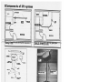
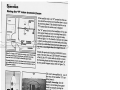
Please refer to figures 1A and lB to see sample floor plans of an installed lift system. Refer to figures 2A and
2B to familiarize yourself with the components of the C4501 C625 lift. Figures 3A and 3B show the underside
view of the lift as it would be seen by an operator.
C450/ C625
-
User Guide
Rev: I8JUNE2OI2
Page: 2
Lu
C,
C,
C,.
C)
C,
C,
UI
C
O
CT’
C.
C,’,
C
C
‘ci
Cl)
0
Cl)
0
-I,
Cl)
m
z
0
C,
0
________________________________
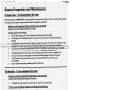
Component List
The following components are included
with your new
•
C4501 C625
lift system:
•
C4501 C625 lift (Manual or Motorized traverse)
Pneumatic Hand Control
Lift Charger (mounted on the wall
or ceiling at the end of the track)
Owner’s Manual
•
Warranty
•
•
Card
SLINGS: If a sling has been supplied with
the lift refer to the instructions inclu
ded with the sling.
ACCESSORIES: If additional accessories
such as a turntable, or gate system
have been supplied with the lift
refer to the instructions included with those item
s.
-IMPORTANT Before initial use, the htt upit
miithicharged for 4-hours-Reereeeti
on-titlez_zzzzz
-‘chaiTng11i-structions’. The hand cont
rol airline tube must also be connected to the
lift. If if is not
connected refer to the section titled “Connectin
g airline to the lift”.
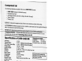
Specifications of C4501 C625 lift
Lift Motor:
Traverse Motor:
“H” Frame Traverse Motor:
Charger Input:
Charger Output:
Batteries:
Lift Case:
Hand Control:
Lifting Range:
Lift Weight:
Maximum Load:
available in 625 lbs.
Duty Cycle:
Rated Performance:
C4501 C625 User Guide
24 VDC
24 VDC
24 VDC
(Optional at time of Purchase)
(Optional at time of Purchase)
hippmatoraae COfldflS7
Relative Humidity:
10 to 100% RH
Atmospheric Pressure: 500 to 1060 hPa
120 VAC, 1.0 Amps
24 VDC, 1.5 Amps
24 VDC (2 x 12 VDC) 5.0 All, Seal
ed Lead Acid
Flame Retardant ABS
Pneumatic
Up to 96” (2438mm)
21—23.5 lbs
Standard maximum load 4501bs. Also
Maximum load of the installed lift is
determined by referring to the product
label located on side of lift.
10% use, 90% rest
3 0-40 lifts at 625 lbs, 50-60 lifts at 450 Ibs, 10%
duty cycle, each lift being 24 inches al
the mi
baUe:
Please note: the lift has a break in period; brea
king in of the lift will need to be done
before these numbers will be achieved. The
breaking in period will vary from lift to lift
and is dependent on the frequency of use and
the types of load being applied, the highei
the load and a greater frequency of use will brea
k in the lift faster.
-
Rev: 183UNE2012
Page: 4
__
_
__
_-
12 l/2
—
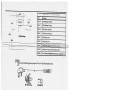
Models Table for
WWflIL1’IOII%
-
I
2 rir
(267n.)
96
(2238)
Lifting Range
(2)
C4501
C625
Lift
Code
Description
323100
C450 Manual Traverse
323117
C625 Manual Traverse
323150
C450 Power Traverse
323127
C625 Power Traverse
323 177
C450 PowerX-Y
323137
C625 PowerX-Y
323 49
C450
323126
C625 Power Traverse c/w Return to Charge
NOTE:
For C Series wIQRS Hook Part
nos.,
See
page no.
16
NOTES:
• Please use the following type of plug for C-450 or C-625 lifts insta
lled in the
UK:
Lf!
II
I
II 133 Uk Plug
•
Please use the following type of plug for C-450 or C-625 lifts installed in Aust
ralia.
.rj
_jj.,,—
•—“—.
AS 11 2 Auglrallari
•
C450/ C25 User Guide
-
IEC 60320.-C?
Plug
-
ECflJ.2O C?
The C-450 or c-625 lift shall be connected to a center-tapped single phase supp
ly cir
cuit when users in the United States connect the equipment to a 240 V supp syste
ly
m.
Rev: 18JUNE20 12
Page: 5
tt Cautions
•
The C4501 C625 must be
installed prior to use. Contact
your local authorized dealer
is properly installed. The C4
to ensure that i
501 C625 must be installed
onl
y by persons authorized by
Glen Systems Ltd.
Waverley
•
—
Under no circumstance sho
uld the C4501 C625 track,
lift and sling (s) or entire sys
trol of a person who has no
tem be put in con
t been properly trained in the
use and care of this equipm
here to this warning may res
ent
Failure to ad
ult in serious injury to the ope
rator, and/or the individual
transferred.
being lifted/
• The C4501 C625 lift,
and associated track and slin
g (s) are not toys. Do not use
tices. Do not allow children
it for unsafe prac
to play with the lift or any of
its’ components.
The uf
rerrsáranty
isLnersnauthen
e&-by’Wvlvu
rkthE
• There are no user ser
viceable parts inside the cov
er. Do not remove cover scr
unit, as this will VOID TH
ews, or open the lift
E WARRANTY.
•
In facilities where more tha
n one operator will be respon
sible for using the C4501
sociated track and sling (s)
C625 lift and as
it is imperative that all such
members be trained in its’
ing program should be establis
pro
per use. A train
hed by the facility to acquai
nt new operators with this
equ
ipment.
•
Never expose the C4501 C6
25 lift directly to water. Wa
rranty does not cover any mi
the lift system.
suse or abuse of
-
-
-
•
To maintain optimum functio
n, the C4501 C625 should
be inspected and maintained
basis. See the section titled
on a regular
“General Inspection and
Maintenance”.
• Any accessories used
with the C450! C625 inc
luding track and sling (s),
ensure that they are in good
should be checked to
working order. Check for sig
ns of wear or fraying prior
unusual wear, or damage im
to use. Report any
mediately to your local aut
horized Waverley Glen dea
ler.
•
The C4501 C625 lift and ass
ociated lift, track and sling
(s) are intended only for lift
transferring of a-person. Wa
ing an&
verley Glen will not be res
ponsible for any damage
neglect or purposeflul destr
caused by the misuse,
uction of the lift, and/or its’ ass
ociated components.
• Do not in any circum
stance exceed the maxim
um allowable load of this lift
“Specifications” sectio
. Refer to the
n of this manual, and/or the
labels on the side of the lift
.
• The installation of
the lift, track, accessories,
and
slin
g
are
cer
tifi
exceed the maximum rated
ed to a maximum load. Do
load of any of the component
not
s,
• There is a risk of
explosion if the lift is used
in the presense of flammabl
e anaesthetics.
• Ensure that a cle
ar space is maintained around
the
lift and track. Move all curtai
obstacles out of the way bef
n material and other
ore performing a transfer.
-
-
•
The charger must be located
outside the patient vicinity
at all times. The patient vic
with surfaces likely contacted
inity is the space
by the patient or an attendant
who can touch the patient
space is 6 feet (1 .83m) beyo
This
nd the perimeter of the bed
, examination table, etc.,
7-1/2 feet (2.29m) above the
extending vertically
floor.
C4501 C62S User Guide
-
Rev: ISJUNE2OI2
Paee: 6
7L
the lift
Attaching the airline tube to
lift to re-attach
order to access the underside of the
á Caution: A sturdy ladder may be required in
should be used when this is required.
the rubber airline of the lift. Caution
ler.
r local authorized Waverley Glen dea
you
tact
con
ns
stio
que
or
s
cern
con
anj
Should you have
-
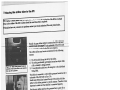
--Should- the-gray rubber airiincthat con
nects the lift to the hand
lift it thusf
be re-connected in order for the lift
ected for the following
The rubber airline may become disconn
reasons:
ed on
Figure 13A Black rubber grommet locat
connected.
not
is
e
airlin
ber
Rub
lift.
of
rside
unde
Note grey rib on grommet.
-
inserted
Figure 13B Gray rubber airline being
on
ribs
black
The
lift.
of
met
grom
into rubber
d pins
both pieces are lined up. The metal ribbe
are on the airline.
-
Pieces connected together
ted
Figure 13C Gray rubber airline being inser
on
into rubber grommet of lift. The black ribs
pins
both pieces are lined up. The metal ribbed
e.
airlin
the
are on
the airline.
1) The lift is pulled along the track by
d around an object while
2) The tubing accidentally gets wrappe
a lift or transfer is being performed.
caregiver or the individual
3) It is accidentally pulled out by the
being lifted.
ber grommet located on the
The airline is connected to a black rub
underside of the lift. Refer to figure 1 3A.
of the airline hold the
Small metal ribbed pins located at the end
cific manner. Therefore it is
airline to this rubber grommet in a spe
is connected properly.
important to make sure that the airline
mmet have a grey rib on
Both the grey airline and the rubber gro
together. Refer to figure
one of their sides. Line up the grey ribs
ribbed pins attached to the
13B. Wheiithisis done then the metal
the corresponding hoIës
end of the airline can be re-inserted into
of the lift. Be sure to in
in the rubber grommet on the underside
et sufficiently so that it is
sert the pins into the grey rubber gromm
secure. Refer to figure 13C.
nectivity. Turn the lift
Perform a brief test to ensure proper con
y bar. For motorized trav
ON and OFF. Raise and lower the carr
t. If these functions work
erse lifts move the lift left and then righ
nected.
correctly then the airline is properly con
ck to ensure that the grey
If the lift does not work properly, che
underside of the lift and
ribs on the grey rubber grommet on the
ly. If they are not lined up
the-airline tilbing are lined up proper
up the gñy littes and then
properly, then remove the airline, Tine
form the test as noted in
re-insert it into the rubber grommet. Per
still problems with the lift
the preceding paragraph. If there are
ler for service.
then contact your local authorized dea
-
r’Asnl C62- User Guide
Page: 7
Rev 183UNE2012
Operation
& Caution: Always, before using
the C4501 C625 lift sy
(s) must be visually chec
stem, the lift, track an
ked for any unusual w
d sling
ear, or damage. Refer
with each piece of supp
to the user manual
lied equipment to dete
rmine what should be
ything look unusual cont
checked. Should an
act your local Waverley
G
ie
n
de
al
er
pr
io
r
to
Failure to comply with
use.
this caution could resu
lt
in
se
rio
dividual being lifted an
us injury to the operat
d/or damage to the lift.
or, the in
Turning the lift ON/O
FF
Refer to figures 4A, 4B and
4C to determine the hand
control that is attached to
the lift.
To operate the lift it mu
st first be turned ON with
the use of the hand contr
on the hand control and
ol. This can be done by
hold at least for two (2
pressing any button
seconds. The indicator lig
turn GREEN and the dis
ht located on the undersi
play screen will turn on.)
de of the lift will
Refer to Figure 4D. If the
the EMERGENCY STOP
lift fails to turn ON at an
! LOWERING CORD ha
ytime, ensure that
s not been pulled and tha
has not come out, see pa
t the plastic c1i at the
ge 13 for details.
end of the red cord
To conserve battery powe
r the lift will automatically
shut off after approximate
If the batteries of the lift
ly 2 minutes on non-use.
are low and require chargi
ng,
ANGE, and a slow beepin
the indicator light located
g audible alarm will sound.
on
The display will also indica the underside of the lift will turn OR
If the batteries of the lift
te low battery.
are completely discharged
and require charging, the
lift will turn RED, and a
indicator light located on
fast beeping audible alarm
the un
will sound. See figure 4E.
The lift will not raise or low derside of the
er and the display
I
Figure 4E Low battery indic
ator
-
C4501 C625 User Guide
-
Rev: 18J1JNE2012
Page:
a
Operation
rry bar
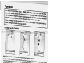
Raising/lowering the ca
By pressing the DOWN arrow
button, or the UP arrow button,
the carry bar can be loweredl
raised to the correct height for
attaching the sling or position
ing an individual. Refer to fig
ure5Aand5B
It is recommended that the care
giVer (operator) hcil& the-carryhisbeing done so that it will not
accidentally sway and/or come
into contact with an individual
or close object. These buttons
work the same on each model
of the lift.
—--
con
Figure 5A Power traverse hand
c
trol showing raising/lowering fun
tions
-
wering of
Figure 5B Lift showing raising/lo
carry bar.
-
-
-
track
Moving the lift along the
Figure 6A Motorized traverse hand
control showing colored buttons.
—
-
charg
The lift is normally parked at the
in
not
en
wh
ing station end of the track
to
ck a
use. It can be moved along the tra
to be
position directly above the person
lifted in one of two ways.
g lift
If you have a manually traversin
comfortable
‘::Dr the carry bar to a
bbedheight such that it can be easily gra
the
by your hand. Move the lift along
, or
bar
ry
car
the
track by gently pushing
l
the
individual in the sling. Never pul
lift along the track.
l move
Figure 6B Lift showing horizonta
ons
versi
rized
moto
for
are
ws
Arro
t.
men
-
colored
sing lift, use the blue or yellow
If you have a motorized traver
low
to move the lift. The blue and yel
directional hand control buttons
un
the
on
ws
yellow directional arro
buttons correspond to the blue and
by
d
refore that is taken is determine
the
ion
ect
dir
The
lift.
the
of
side
der
tter
ssed This works the same no ma
the color of the button that is pre
and
nding on. Refer to figures 6A, 6B
sta
is
son
per
a
lift
the
of
side
at
wh
6C.
e when moving the lift along the
Caution: Always use extreme car
se injury
any obstructions that may cau
track. Watch out for and avoid
/or damage to the lift.
to the individual in the sling and
Page: 9
Re’: 183UNF2012
___
_____
____
___
__
__
__
Operation
Moving the “H” system tra
versing beam
BATH
TRAVERSING
\BEAM
I
—
BED”.\
_.[I
T
BATHROOM
I
\
LIFT
SUPPORT
CHARGlNG—
CHARGE
D:OM
Figure 7A Sample of”H” sys
tem room covering layout. Not
e that the
lift can be moved along the trav
ersing beam, and that the trav
ersing
beam itself can be moved along
the two parallel support tracks.
The actual direction of travel whe
n
may be different than shown, sinc the hand control buttons are pressed
e the track and lift orientation
may be
different than installed..
-
Figure 7B Power traverse “H”
system hand control showin
g
traversing beam movement
buttons. Button colors corre
spond to the black and white
directional arrows located
on the
underside of the lift.
-
If the installed track is an “H
” system then this sec
tion should be reviewed as it
describes how to move
the traversing beam. If the ins
talled track is not an
“H” system then this section can
be skipped.
The “H” system involves the
installation of two par
allel support tracks and one tra
versing beam that is
mounted perpendicular to the
two support tracks.
Refer to figure 7A. The benefi
t of this type of system
is that it provides greater movem
ent and positioning
nhil ily
andividual-sinee-thefleersp
aeeeover——
..age area
track.
Besides the previously descri
bed UP/DOWN move
ment of the cany bar, and LE
FT/RIGHT movement
of the lift, the “H” system add
s the ability to move
the traversing beam anywhere
along the length of
the two parallel support tracks
. Refer to figure 7A.
This can be accomplished in
one of
two ways. If the installed “H
” tray
I ersing beam is
manually traversing then the
beam is moved along the suppor
t
tracks by manually moving the
i beam, lift, and
individual in one mo
tion. This movement is the sam
e as
:t-used-for-a manual traversin
g
lift, as previously described.
Figure 7C Directional arrows
on underside of power
If the installed “H” system tra
traverse “H” system lift. Bla
vers
ck and white arrows show ing
bea
m
traversing beam direction of
is
mo
tor
ize
d
tra
ve
rsing
travel when the corresponding colored button is pre
ssed on the hand control. then the beam is moved along the
support tracks by pressmg eith
black or white hand control
er the
button. Refer to figure 7B.
This will move the beam
in the direction of travel as not
ed by the black [VJ and wh
ite arrows [ ]located
on the underside of the lift.
Refer to figure 7C.
-
Caution: Always use extre
me care when moving th
e traversing beam. Watch
and avoid any obstructio
out for
ns that may cause injury
to the individual in the sli
age to the lift/track.
ng, or damt
C4501 C625 User Guide
-
Rev: I8JUNE2OI2
Page:
10
Return To Charge (If Equipped)
If your motorized, traversing lift has a return-to-charge feature (RTC),
pressing & holding the blue and yellow colored directional hand control
buttons simultaneously for 3-5 seconds (to produce beeping noise) will
automatically retract the lift’s carry bar and drive the lift along its track
until it docks at the charger.
-
3USJ WV
Press & Hold the blue
The new weight sensitive adaptive return-to-charge feature offers add
ed protection during RTC movement. The salient features of new “Load
Sensitive RTC” are as under
1’
bled RICwhilea natient is
•1
.....
uu
I
-..-.
U1tJA jIQIZU S,UIILLLJI ULSLLSJII3 alhilur
taneously to activate the RTC feature.
cess load on the lift dUringRTC. The overload threshold is between
3 5-50 lbs.
2) During RTC, if lift carry bar accidentally gets tangled with obsta
cles Furniture, drapery etc., the lift will automatically detect the
change in the load and if any variation of more than 15-20 Lbs. is de
tected the lift will stop automatically.
,
Note:- RTC feature can always be interrupted manually by either
pressing any buttons on the hand control or by holding the carry bar
firmly.
Note that the RTC feature has several characteristics that may be altered
to the user’s preference:
RTC Max. Time may be set anywhere from 60 sec to 240 sec in 60 sec
increments and represents the maximum time allowed for the lift to travel
to and dock at the charger before aborting the operation.
RTCDrop Time may be-setanywhere from9 see to-24sec-in3 see-incre-—-_.
ments and represents the time the lift devotes to lowering the carry bar
upon docking at the charger.
RTC Speed may be set to 2, 4, or 8 and represents the relative speed the
lift travels at to reach the charger.
Contact your Service Technician to change these settings.
Caution: Always ensure the carry bar is attached to the lift before activating RTC function. The
added weight of the carry bar is required to ensure correct working of limit switches. Failure to
have carry bar attached cnresuit in limit switch error., refer to “Troublcshoting” Secthm at page 23
for recommended solution.
4th Caution: Always use extreme care when moving the traversing beam. Watch out for and avoid
any obstructions that may cause injury to the individual in the sling, or damage to the lift/track.
C4501 C625 User Guide
-
Rev: I8JUNE2OI2
Page;
11
Basics in transferring
an individual
& Caution: The follow
ing steps are intended to
generally illustrate the
and transferring of an ind
procedure involved in the
ividual from one location
lifting
to another using the lift,
figurations will vary by
track and sling. Track
installation.
con
The manual for the sling
that was purchased with
the lift should be review
ing these steps, as the sli
ed in detail prior to atte
ng illustrated here may
mpt
not .be the same as the on
Contact your local au
e
that was purchased.
thorized Waverley Glen
dealer if you have any
questions or concerns
.
Step 1) Move the lift away
from the charging station
or current location and clo
transferred. Use the proce
se to the individual that
dures for up and down an
is to be
d moving along the track
“Raisingllowering th
as described in the sections
e lift” and “Moving th
e lift alon
titled,
g the track”
avoid any obstructions
that may cause
lift/track.
movinj the lift along the track. W
atch out for and
injury to the individual in the sli
ng, or
damage to the
Step 2) Prepare the individu
al being transferred with
appropriate sling. Refer
with the sling that was purch
to the instructions supplie
ased on how to properly the
d
outfit an individual with
a sling.
Caution: Always make
sure that the sling is co
rrectly fitted and adjuste
individual so that maxim
d on each side of the
um comfort and safety
are achieved prior to liftin
g.
Step 3) Once the individual
has been outfitted with the
sling, move the lift so tha
the individual. Lower the
t it is positioned directly
carry bar to a height so tha
over
t the straps of the sling ca
bar.
n be easily attached to the
carry
& Caution: Alwa
ys check to ensure that
the lift is correctly posit
son to be lifted. Over tim
ioned directly above the
e, the lift strap may fra
per
y if this is not followed
.
th Caution:
Check to ensure that the
carry bar has no cuts, de
come in contact with the
nts or sharp edges that
straps of the sling and ca
may
use damage to them. Re
your local authorized de
port any concerns to
aler.
Step 4) Attach the straps of
the sling to the hooks of
the carry bar. The strap
erally attached to the corre
s on each side of the sling
sponding side of the carry
are gen
bar. Be sure to double ch
properly attached to the ca
eck to ensure that the strap
rry bar, and that the indivi
s are
dual being lifted is prope
lifting.
rly positioned in the sling
prior to
Caution: Prior to lifting
an individual make sure
that the straps of the sling
placed on the hooks of the
are securely
carry bar.
Step 5) The individual ma
y now be raised with the
use of the-Ul button on
in progress -theheightreq
the hd contri While lif
dinöider for the transfer
ting is
to be completed safely
sure that the individual be
should be closely observe
ing lifted will not be inj
d. En
ured by any obstructions
during the initial lifting.
Caution: Always use ca
ution when lowering/raisi
ng an individual who
lift. Watch out for and
is in the sling of the
avoid any obstructions
that may cause injury
age to the lift.
to the individual, or dam
C450I C625 User Guide
-
Rev I8JUNE2OI2
-
Page: 12
Z!E
3asics in transferring an individual
...
continued
to
n.
Step 6) Once at the correct height the individual can be moved along the track to the desired locatio Refer
the sectioas already described in this manual on how to move the lift along the track
in
Step 7) Once at the desired location the individual in the sling can be lowered/raised to the correct height
order to complete the transfer. On completion of lowering/raising ensure that the individual is properly posi
tioned and safely supported prior to removing the straps of the lift from the carry bar.
Caution: Prior to removing the straps of the sling from the carry bar be sure to check that
the individual bçg lifted is securely supported m the final desired position
Step 8) Lower the carry bar sufficiently to allow the straps of the sling to be easily removed from the carry
sling
bar. Take care not to let the carry bar come in contact with the individual in the sling. The straps from the
lift
the
and
ently
suffici
raised
be
then
can now be removed from the carry bar. The carry bar of the lift should
indi
the
from
moved away from the immediate area so that it will not interfere with the removal of the sling
vidual.
for
Step 9) The sling can now be gently removed from the individual. It should then be stored in a safe place
future use.
Step 10) The lift can now be moved to a safe location until further use, or relocated to its’ original location.
The lift should be turned off when not in use. It is recommended that the lift be left on charge when not in op
eration. Refer to the section titled, “Charging the lift” for instructions on charging.
Optional Hand Control Book
the
Your lift has come with an optional Hand Control Hook. This Hand Control Hook can be installed onto
l
Contro
Hand
of
the
back
On
the
Hand Control using the self tapping screws provided with the plastic hook.
there will be 2 small pilot holes where the self tapping screws should be screwed into. See figure 7D for a
hook
Hand Control with the Plastic Hook already assembled. Figure 7E demonstrates the use of the plastic
with your lift.
c4c0! C625 User Guide
-
Rev: 183UNE2012
Page: 13
I
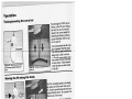
Charging the lift
The charger contacts with two
metal charging strips that
run along the inside of the tra
Whenever the lift is over a sec
ck.
tion of track with charging
strips it will automatically
the lift if its battery is low.
start to charge
The batteries should be charge
d on a regular basis. It is rec
ommended that the lift be lef
when not in operation, and at
t on charge
the end of each day. This wil
l maximize the life cycle of
the batteries
The lift may remain connec
ted to the charger indefmitel
y since the charger has a bui
ehnunating the danger of ove
lt-in regulator,
rchargmg
generalzrulitisi ëÔO
i inëñd
interfere with anything or any
one
—
ecarrybarbe raised to a hei
ght so that it will not
while the unit is not in use.
The light will turn ORANGE
on the lift control
panel and a slow beeping aud
ible alarm will sound
if the batteries are low and
require charging. The
display screen will also ind
icate low battery.
Complete the transfer that
is in progress and then
move lift to the end of the tra
ck where the charger
is located.
L_.__
Figure 8A Underside of lift
showing RED dis
charged battezy indicator light
ON. A fast beeping
will be sounded. When the
lift is connected to the
charger this light will be OR
ANGE indicating that
the batteries are charging.
-
Following the ORANGE ind
icator, the light will
turn RED on the lift contro
l panel and a fast beep
ing audible alarm will sound
indicating the batter
ies are fully discharged and
require charging. The
display screen will also ind
icate low battery.
When the battery is discharg
ed the UP function
will be disabled. The DOWN
and EMERGENCY
DOWN function along wit
h X-Y TRAVERSING
will continue to operate.
When the lift is charging and
turned ON, the indicator light
on the lift will FLASH OR
the lift is turned OFF the ind
ANGE Once
icator light will change to
a
sol
id ORANGE. This indicates
on charge.
that the lift is
.
á Caution: Use only
the charger that was supp
lied with the lift. Use of
warranties and may caus
any other charger will vo
e damage to the lift.
id all
C4501 C625 User Guide
-
Rev: I8JUNE2OI2
Page:
14
After one hour, the lift may be used, however,
overnight charging is recommended. The
EMERGENCY DOWN functiàn.along with X
Y TRAVERSING will continue to operate.
In addition to the indicator lights on the lift, the
charger has an indicator light. When ORANGE,
it indicates that the batteries are low and being
,-
:
Figure 9A Charger close-up showing charging indicator
light is ORANGE indicating that the lift is connected and
is charging.
-
When the light on the charger is GREEN, bat
teries are fully charged. Note: In some circum
stances it may be necessary to mount the charger
out of view.
Constant Charger
The constant charger system has two
metal roller bearings (Figure 9B) that
contact charging strips that run along the
inside of the track. When the lift is over
a section of track with charging strips it
will automatically start to charge the lift
if its battery is low.
When the Constant Charger is charging
and the C-450/C-625 is turned ON, the
indicator light on the lift will FLASH
ORANGE When the lift is turned OFF
the indicator light will change to a solid
ORANGE. This indicates that the lift is
on charge.
.
The Constant Charger can be attached to all operating C-450 or C-625 lifts. The batteries can
remain connected to the charger indefinitely, since the charger has a built-in regulator, the danger
of overcharging is eliminated.
C4501 C625 User Guide
-
Rev. 18JUNE2OI2
Page: 15
Attaching the QRS Carry Bar to the Quick Release Hook
UI
Figure 1 OA Insert the Dowel Pin of cariy bar into the
Quick Release Hook
-
Your lift has come with a Quick Release Hook attached to the lift strap. To attach the carry bar to Quick
Release Hook, push the dowel pin of carry bar to the latch so that latch will open and dowel pin will be
inserted into the Quick Release Hook as shown in figure 1OA. Make sure the latch is closed safely after
the Dowel Pin sitting into the Quick Release Hook as shown in figure lOB. If the latch does not close
safely or does not comes to its original position as shown in figure lOB, then DO NOT USE QUICK
RELEASE HOOK, and contact your local authorized dealer.
Models TabJe for C450 / C625 Lift with QRS Hook
Code
Description
323700
C450 Manual w/QRS Hook Assy.
323717
C625 Manual w/QRS Hook Assy.
323750
C450 Power w/QRS Hook Assy.
323727
C625 Power w/QRS Hook Assy.
323777
C450 Power XY, w/QRS Hook Assy.
323737
C625 Power XY w/QRS Hook Assy.
323749
C450 Power-RTC wIQRS Hook Assy.
323726
C625 Power RTC w/QRS Hook Assy.
C4IC625 User Guide
-
Re
1RJTTNE2O12
Page:
16
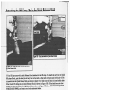
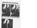
Detaching the QRS Carry
Bar from the Quick Relea
se Hook
rEEEE
Figure 1 IA Detaching the Carry
Bar from Quick Release
Hook
-
Figure 1 lB Detaching the Carry
Bar from Quick Release Hook
Figure 1 IC Tilt the Carry Bar
to remove from Quick Release Hoo
k
-
-
I
To detach the carry bar from the
Quick Release Hook, Open the
latch by pushing the latch down
fmger as shown in figure 1 1A, and
using the
11W Keep the latch pushing dow
n, Tilt the carry bar approximate
degree, and remove the carry bar
ly 90
from the quick release hook as sho
wn in figure 1 1C.
C450/ C625- User Guide
Rev; 18flJNE2O12
Page; 17
Lif
LCD Display Functionality
Default Display Modes:
The lift unit can be set to either of the following as the ‘Default’ display mode:
1.. Battery Level (the factory setting for the Default Display Mode); or,
2. Number of Lifts.
To change from one operating mode to another please call your local service technician.
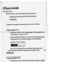
In Battery Level Mode the lift will:
LI.JJJ
-
row of the display (e.g., “Battery Level 60%”).
2.
Display a “Bar Graph” of the battery level in the second row of the display by displaying
the appropriate number of fully blackened rectangles as in the following diagram:
Ba t
ter y
5.0%
liii..
Note: As the lift is initially switched on, the level of battery charge displayed may be
incorrect. However, as soon as the lift is actually operated, the charge level will up
to the correct level.
date
In Number of Lifts Mode the lift will:
3. Display the word, “Lifts”, with the number of lifts completed in the top row of the display
(e.g., “Lifts 500”) and a bar graph to indicate the battery level as in Battery Level Mode:
tsxx
“III
In any ‘Default display mode’, if the battery levels fall below 25%, the lift will go into Low Battery
Mode. The lift will then:
4. Make an audible beeping sound every ten (10) seconds.
5. Flash “Low Battery” in the first line.
6. The bars indicating charge level will flash on and off.
C450! C625 User Guide
-
Rev: 183UNE2012
Pane: 18
LCD Display Functiona
lity
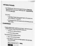
In any ‘Default display mode’
, if the unit is in the charger
the lift will go into Charging
Mode regardless what the use
Display
r has selected as ‘Default Displa
y Mode’. Charging Displa
will over-ride Low Battery
y Mode
Mode.
The lift will then:
-
7. Display a flashing “Chargin
g” with the percentage charge
d (in 10% increments) in the
top row of the display (e.g., “C
harging 60%”).
8. Show the appropriate num
ber of fully blackened out cel
ls, with the remaining cells
bottomrow
in the
fiashing.__
_PreventatiyeMajncnance—-—__________
—-—ZEEE
r--——
E
Preventative maintenance sho
uld be completed every six (6)
months. The lift should recom
preventative maintenance if
mend
it hasn’t had any preventative
maintenance for:
1. 1,000 lifts (four or five
lifts a day 180 days); or,
2. Five (5) hours of continuou
s operation
When recommend preventati
ve maintenance, the lift will:
9. Beep one (1) time every
thirty (30) minutes
10. Flash “Maintenance” in the
first line of the display (regardle
ss of which default display
mode the user has selected).
M a I n t[e n a n c e
I’ll”
<—Flashing
To reset the PM lifts counter:
(2 options to reset)
A.
1. The lift must be in power off
state.
2. While pressing both Up/Do
wn buttons on hand control, tur
n “ON” lift. Mode “Tech
Prog” will show on LCD dis
play with beep.
3. Follow the instruction “UP:
RST PM Lift” on LCD and pre
ss UP button. A minimum
10 seconds must pass followed
of
by a beep to indicate comple
tion of the reset.
4. PM lifts count will be “ze
ro”.
5. Use lift as normal.
B.
1. The lift is in power on state
but LCD is in blank status.
2. Press both Up/Down button
s on hand control to active mo
de “Teeh-Prog” on LCD dis
with beep.
play
3. Repeat the same procedure
s from step 3 to 5 as shown in
option A to finish reset.
-
-
C450( C625 User Guide
-
Rev: 18JUNE20 12
Page:
19
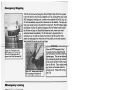
Eniergency Stopping
Pull
Don
Once
The lift unit also has an Emergency Shut-off feature that allows the operator
to shut the power to the lift unit completely off. By pulling down once on the
RED emergency lowering cord, located on the underside of the lift unit, the
lift will immediately stop and all its functions will be disabled. The unit will
beep once and all power to the lift will be turned off. The ON Indicator light
and display will turn off, and the Emergency Shut-off button located inside
the lift case will pop out. Should this feature be used, contact your local
authorized dealer immediately. The lift unit must be inspected prior to
restoring to use. In order to restore power back to the lift unit, the white
plastic tab that popped out when the cord was pulled, can be easily pressed
back into the lift case by use of your fmger.
Once the RED Erneigëiir SthpT
Lowering Cord is released the lift
unit will need to be reset in order to
operate-again. This can be achieved
buy pressing the plastic tab located
at the end of the RED CORD, back
into the lift unit. Then, simply press
any button on the hand control to
resume power. Please refer to Fig
ure 12B.
-
Figure 12A Pull down on the
RED CORD once to stop the lift.
The unit will beep once and all
power to the lift will be turned off.
-
I—
-
Figwe 12B Return power to the lift
unit by pressing in the plastic tab
—
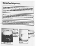
Emergency Lowering
0s
:.i;
In the event that the DOWN button on the hand control does not function,
or in- powerfailure situations, the personmayhe lowered byp11ing down
and holding the RED emergency lowering cord located on the underside of
the lift unit. Continue to pull down until the person is safely lowered to the
desired position. The unit will beep as you continue to pull down on the
cord and will continue beeping until the cord is released after the desired
lowering has been achieved. Please refer to figure 1 3A.
IMPORTANT: The Emergency Lowering button does not provide a rais
ing function. The failure of any of the lowering devices should be reported
to Waverley Glen or your authorized dealer immediately.
Figure 13A Pull down and hold
until the person is safely lowered to
the desired position.
-
C4501 C625 User Guide
-
Rev: 18JIJNE2OI2
Page: 20
Emergency Manual Raising or Lowering
Caution: The manual emergency raising and lowering
system should be used only if the lowering
procedures described in the previous section of the man
ual do not work, or, if the emergency raising
function is required. Should you have any concerns or ques
tions contact your local authorized Waver
Icy dealer.
£ Caution: A proper safety ladder or stool may
be required in order to remove the cover of the device.
Use extreme caution if this is required. Should you have
any concerns or questions contact your local
authorized Waverley Glen dealer.
Caution: DO NOT use the lift after the manual lowering
mechanism has beettused. The liftmust be reset
by a qu dfltçcjçtiftusecontactyowI1ocalauthmized—Wav
erIey GIn ikih.,zzzzzj
‘
-
—
-n
Step 1) Carefully
remove the cover of
the lift by pulling
down on both sides
of the lift cover. Re
fer to figure 14A.
1
Step 3) Locate a
small circular clip on
one side of the lift.
Refer to Figure 14C.
Remove this clip and
-roceed to Step 4.
I
Figure 1 4C Remove clip from side of the lift.
rFigure 14D Turn the Allen Key to lift!
lower the lift strap.
-
-
Step 2) Locate the
Allen key in the plastic
bag containing the
owners manual, clevis
pin & ring, and hand
control.
rFigure 1411— Locate Allen Key sup
plied with the lift.
Figure 14A— Remove lift cover.
C4501 C625 User Guide
-
-
Rev: I8JIJNE2O12
Step 4) Insert the
Allen key into the
hole discovered after
removing the clip
and turn the key with
your fmgers. Refer
to Figure 14D. Turn
the clockwise to
lower the lift strap
and counter clock
wise to raise.
Page: 21
Cleaning and Disinfection
using isopropyl alcohol. Damp a cloth with isopro
The exterior of the lift should only be cleaned, disinfected
used
and hook. No other chemicals and/or liquids should be
pyl alcohol and wipe down entire exterior of lift
to clean, disinfect and sterilize this lift.
inside
Caution: Take great care to ensure that no liquids get
to
Failure
tight.
the lift. This lift is not drip proof or water
lift and]
protect the lift from liquids may result in damage to the
or may cause personal inju.
RTU (Ready-to-use) available from:
The lift strap may be disinfected using Virox Accel TB
Virox Technologies Inc.
l8OO_387-7578
www.virox.com
C4501 C625 User Guide
-
Rev: ISJUNE2OI2
Page: 22
Fault Finding
Should problems arise with
the use of the lift review the
following chart. Find the fau
ornmended solution. If the fau
lt and complete the rec
lt is not found and/or the sol
ution does not correct the pro
Waverley authorized dealer
blem contact your local
for service immediately.
Fault
The airline tubing that connec
ts the
hand control to the lift has bec
ome
disengaged.
Recommended Solution
V
Refer to the section of this man
ual titled “Attaching the air
line tube to the lift”.
If this does not correct the pro
blem then contact your local
authorized dealer immediately
that the lift can be checked to
so
ensure proper continued ope
ration.
The hand control buttons do
not op- The airline tubing
has not been connected correct
erate according to their design
ly. Refer to the section of this
ations “Attaching
manual titled
the
(e g the UP bun
airline and hand contr
atesaycrsc theol
to
the
lift
tins
doe
pro
blem
¬correct_.
iitöment).
hecked4o=ensu eprope
thi
Ion.
The carry bar of the lift doe
s not op.
V
V
erate up or down even when the
airline has been properly connected.
The indicator light on the con
trol panel
located on the underside of the
Press the ON button or UP/DO
lift should be GREEN.
WN arrow buttons or any colo
ured button on the hand con
This should activate the lift
trol.
and the indicator light turn GR
EEN
.
If the lift still does not functio
n, then the batteries may be low
and require charging. Refer to
the section of this manual title
d “Charging the lift”. Cha
rge the lift for at least one hou
and then try to raise/lower the
r
carry bar.
The GREEN light on the und
ersi
of the lift is ON and the lift does de
not
operate in the DOWN direction,
The red indicator light on the und
erside lift turns RED and/or a lou
d
alarm sound is heard when an md
ividual is raised.
If the emergency loweri
ng has been used then the UP and
DOWN functions will not op
erate. DO NOT use the lift. Con
tact your local authorized dea
ler
can be checked to ensure proper
immediately so that the lift
continued operation.
There is a built-in slack tape dete
ctor in the lift. This may be sen
carry bar while pressing the DO
sitive. Apply weight to the
WN button. If this corrects the
problem temporarily but not
permanently then contact you
r local authorized dealer so that
the lift can be checked to en
sure proper continued operation.
The batteries are low and require
charging. Refer to the section
of this manual titled
‘Charging the lift”. Cha
rge the lift for at least one hou
r
and
then try to raise/lower the
carry bar.
.
V
V
V
-
One side of the lift tape (strap)
is
starting to fray after continued
use
.
If this does not correct the problem
that the luff can be checked to ensurethencontact your local authorized dealer inimediatelyso
proper continued operation.
Check to be sure that the lift
is always directly above the ind
ividual being lifted, especially
with motorized traversing lifts
. Refer to the section titled “B
asics in transferring an
individual” for correct lift
positioning. If fraying still con
tinues then contact your loca
authorized dealer immediately
l
so that the lift can be checked
to ensure proper continued ope
ation.
r
The lift does not pass through
a track Refer to the “Owners
Manual” for the specific piec
component such as a turntabl
e of equipment in question.
e or
men
ded
solu
tion
If the recom
doe
s
not correct the problem then
gate.
contact your local authorized
mediately so that the lift can
dealer im
be checked to ensure proper
continued operati
on.
No Power.
Ensure the Emergency Lowering
tab has not come out. If it has
, simply press the tab back
into the lift.
C450/ C625 User Guide
-
Rev: 18JUNE20 12
Page: 23
General Inspection and Maintenance
A) Each Use
-
To be completed by User
Prior to each use the C4501 C625 lift and associated track, accessories and sling (s), must be visually inspected. Refer
to the accessory and sling user guides for specific details regarding their inspection.
Should any of the these items fail the inspection do not use the lift
Contact your local authorized dealer for service.
Visually check for the following:
D
D
o
o
D
o
o
o
The lift lifting tape shows NO signs of fraying or breaking along its entire length.
The stitching on the lift lifting tape where it connects to the carry bar shows NO signs of fraying, or
breaking.
be used shows NO signs of unusual wear and tear. The straps of the sling that connect
hft show NO igiiaffrayihgbfakurg Refurto-specrflmg-mstrucions
The airline tube that connects the hand
All the functions on the hand control work correctly (e.g. UP/DO WN/.LEFT/RIGHT, etc..).
The brackets that hold the track in place on the ceiling are secure and do not move or appear loose.
There are not cuts, dents or sharp edges on the carry bar that may damage the straps of the sling.
The lift has no unusual sounds when the carry bar is moved UP/DOWN or the lift is moved
LEFT/RIGHT.
Ensure that there are end stops installed at each end of the track.
B) Monthly To be completed by User
-
Should any of the these items fail the inspection do not use the lift.
Contact your local authorized dealer for service.
o
Complete the visual inspection as noted in the “Each Use” section above.
With no one in the sling nor attached to the lift check the following:
o
The lift moves freely along the entire length of the track.
C) Semi-Annual or Yearly
-
To be completed by a lift technician
Consult your local authorized dealer for advice on whether this section should be completed every 6
months or on a yearly basis. Generally, in frequent use, or in situations where heavier than normal
clients are lifted, or in multi-user environments such as in institutions the lift should be checked every 6
months
tt
o
This section to be only completed by a qualified service technician as authorized by Waverley
Complete the visual inspection as noted in the “Monthly” section above.
Complete the preventative maintenance procedure as outlined in technical manuals for the
C4501 C625 system.
o
C4501 C625 lift checked and passed. Any required repairs completed.
C4501C625. User Guide
Rcv: 1SJUNE2OI2
Paee: 24
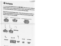
Lift Accessories
The following is a list of
available accessories for
the C4501 C625 lift. Items
brackets are installed at the
such as the track, turntable
time of purchase. Add-on
s and
pieces are available to aft
your local authorized deale
er the initial purchase, howe
r must be consulted as to su
ver
itability, purchase and ins
tallation.
Slings are the most comm
on after purchase accesso
ry. A variety of styles, sizes,
tom slings can also be ma
and colors are available.
nufactured to meet special
Cus
needs. Consult your local
pricing and a complete lis
au
thorized dealer for details,
t of current sling models.
TRACK
L82MTR (6FT)
2.5MTR (aFT) LENAND
GT .
MAY BE CUT AT TIMHS
OF INSTALLATION E
TRAC
5.OMTR (I6FT)K LENGTH
MAY BE CUT AT TIME
OF INSTALLATION
--
-
—
--—
—
---
-
—-
TRACKPLUS TRACK
5.OMTR {I6
AND
6.OMTR (19.5FT)FT)LEN
GTHS.
MAY BE CUT AT TIM
OFINSTALLAETION
--—
--—
—
i
TRACK
45 DEGREE CURVE
MAY BE CUT AT TIME
OF INSTALLATION
TRACK
90 DEGREE CURVE TRANSGATE SYSTEM
MAY BE CUT AT TIME
OF INSTALLATION
qL,
TRACK END STOP
“H SYSTEM TR LEY SET
USED ONLY WITHOL
FRAME
AREA COVERIN “H’
SYSTEM
(MANUAL OR MOGTO
RISED)
WALL MOUNT
BRACKET
3” TRACK
BRACKET
6” CONNECTOR
BRACKET
ACCESSORIES
T TO SCALE.
FOR ILLUSTRATIVENO
PURPOS
ES ONLY.
VARIOUS STYLES AND SIZES
OF SLINGS.
CUSTOM SLINGS AVAILAB
LE.
4
NOTICE: ACCESSORY SIZ
STYLE SHAPE, LENGT
CONFIGURATIONS, OPEiIO
H,
NS
SPECIFICATIOtIS ÔOLOURS AND
MAY CHANGE WITHOUT PRI
OR WRITTEN NOTICE.
CONTACT YOUR LOCAL
AUTHORISED DEALER FO
R DETAILS.
CAUTION: ONLY SLIN
GS AUTHORIZED BY
WAVERLEY GLEN
ARE TO BE USED WIT
H THIS LIFT. CONTAC
T YOUR LOCAL
AUTHORIZED DEALER
FOR DETAILS.
C450! C625 User Guide
-
Rev I8JUNE2OI2
Page: 25
_______________________
__________________________
__________________________
_________________________
___
__________________________________________
_______________________________________
___________________________________________
____________________________________________
____
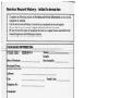
Service Record History
-
Initial Information
•
Complete the following section on Purchase and Service Information as soon as this
equipment is installed.
• Use the service record history to record to any completed service and repairs.
• Ensure that the service record is signed and dated each time it is used.
• Be sure to have this piece of equipment serviced on a regular basis as described in the
General Inspection and Maintenance Section.
PURCHASE INFORMATION:
icfNamc:C45oT625ir
Date of Purchase:
Modh
Serial#:__________
Date Installed:
—
Purchased From:
(local authorized Waverley dealer)
Address:
City:
Postal Code:
Telephone No:
Comments:
SERVICE INFORMATION:
Contact the following company for service:
Company:
(local authorized Waverley dealer)
Address:
City:
Postal Code:
Telephone No:
Comments:
C450! C625 User Guide
-
Rev: I8JIJNE2O!2
_____
____________________________________
__
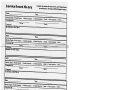
Service Record History
Complete this section after each service, repair
inspection and/
or maintenance. Photocopy additional pages as
required.
Date:
—
Time:
Service Type: c Periodic Inspection
Completed By:
Company
Remarks & Action laken:
ci
Monthly Inspection
ci
6 Month Inspection
ci
Printed Name
Repair
ci
Yearly Inspection
ci
Other:
Signature
—
-
-
Date:
Time:
Service Type: ci Periodic Inspection
Completed By:
ci
Monthly Inspection
ci
6 Month Inspection
ci
Repair
ci
Yearly Inspection
ci
Other:
PrintedName_____—
Remarks & Action Taken:
Date:
Time:
Service Type: ci Periodic Inspection
Completed By:
Company:
Remarks & Action Taken:
ci
Monthly Inspection
ci
6 Month Inspection
ci
Printed Name
Repair
ci
Yearly Inspection
ci
Other:_________
Signature
Date:
Time:
Service Type:
ci
Periodic Inspection
ci
Monthly Inspection
ci
Completed By:
Company:
Remarks & Action ‘laken:
6 Month Inspection
ci
Printed Name
Repair
ci
Yearly Inspection
ci
Other:_________
Signature
Date:
Time:
Service Type:
ci
Periodic Inspection
ci
Monthly Inspection
ci
Completed By:
Company:
Remarks & Action Taken:
6 Month Inspection
ci
Printed Name
Repair
ci
Yearly Inspection
ci
Other:_________
Signature
Date:
Time:
Service Type: ci Periodic Inspection
Completed By:
Company:
Remarks & Action Taken:
C450/ C625 User Guide
-
ci
Monthly Inspection
ci
6 Month Inspection
Printed Name
ci
Repair
ci
Yearly Inspection
ci
Other:_________
Signature
Rev:
ISJUNt2U52
Page: 27
__________________________
________________________
___________________________
_______________________________________
___________________________
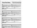
Complete this section after each service, repair inspection and)
or maintenance. Photocopy additional pages as required.
Service Record History
Date:
Time:
Service Type: a Periodic Inspection
Completed By:
a Monthly Inspection
c 6 Month Inspection
Printed Name
a Repair a Yearly Inspection
c Other:_________
Signature
Company:
Remarks & Action Taken:
Date:
Time:
Service Type: a Periodic Inspection
Chmpleted By:
—
—-
-
-
a Monthly Inspection
a 6 Month Inspection
PildN,uia
—
a Repair a Yearly Inspection
a Other:_________
Signature
Company:
Remarks & Action Taken:
Date:
Time:
Service Type: a Periodic Inspection
a Monthly Inspection
a 6 Month Inspection
a Repair a Yearly Inspection
a Other:_________
Completed By:
Printed Name
Signature
Company:
Remarks & Action Taken:
Date:
Time:
Service Type: a Periodic Inspection
Completed By:
a Monthly Inspection
a 6 Month Inspection
Printed Name
a Repair
Yearly Inspection
a Other:_________
a Repair a Yearly Inspection
a Other:_________
ci
Signature
Company:
Rema
Date:
Time:
Service Type: a Periodic Inspection
Completed By:
a Monthly Inspection
a 6 Month Inspection
Printed Name
Signature
Company:
Remarks & Action Taken:
Date:
Time:
Service Type:
ci
Periodic Inspection
a Monthly Inspection
ci
6 Month Inspection
a Repair a Yearly Inspection
a Other:________
Completed By:
Printed Name
Signature
Company:
Remarks & Action Taken:
C4501 C625 User Guide
-
Rev: 18J1JNE2012
Page: 2
__________________________
__________________________
_____
______
_______________________________________
_______________________________________
________________________
______________________
____________________
______________________
_______________________
_______________________
_________________________
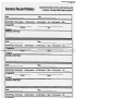
S ervice
-
_________________________
_____________________
_______________________
_______________________
_____
Complete this section after each service, repair inspection and!
or maintenance. Photocopy additional pages as required.
—
is ory
ecor
____
Time:
Date:
Service Type: n Periodic Inspection
o Monthly Inspection
c 6 Month Inspection
c Repair u Yearly Inspection
c Other_________
Completed By:
Printed Name
Signatwe
Company:
flTernarks & Action Taken:
Time:
Date:
Service Type: n Periodic Inspection
c Monthly Inspection
a 6 Month Inspection
a Repair a Yearly Inspection
a Other:_________
completed By:
——
PamdNam-—
Signa--
Company:
Remarks & Action Taken:
—
—
_---
---
—
-
-
-
Time:
Date:
Service Type: a Periodic Inspection
Completed By:
a Monthly Inspection
a 6 Month Inspection
Pnnted Name
a Repair a Yearly Inspection
a Other:_________
Signature
Company:
Remarks& Action Taken:
Date:
Time:
Service Type: a Periodic Inspection
a Monthly Inspection
a 6 Month Inspection
a Repair a Yearly Inspection
a Other_________
Completed By:
Printed Name
Signature
Company:
Remarks-&-Action
Taken
——___________
Date:
Time:
Service Type: a Periodic Inspection
a Monthly Inspection
a 6 Month Inspection
a Repair a Yearly Inspection
a Other:_________
Completed By:
Printed Name
Signature
Company:
Remarks & Action Taken:
Date:
Time:
Service Type: a Periodic Inspection
a Monthly Inspection
a 6 Month Inspection
a Repair a Yearly Inspection
a Other_________
Completed By:
Printed Name
Signature
Company:
Remarks & Action Taken:
C450/ C625 User Guide
-
Rev: 18JUNE2OI2
Page: 29
Warranty
This Warranty does not affect or in any way limit your Statutory Rights
1) Subject to the exclusions set out in Clause 2, the conditions set out in Clause 3 and the limitations set out in
Clause 4, Waverley Glen, as sole licensed representative of Corven Healthcare Inc., guarantees all
equipment supplied as new against failure within the period of 1 year from date of purchase by virtue of
defects in material or workmanship.
2) This guarantee does not apply to failure attributable to normal wear and tear, damage by natural forces,
user neglect or misuse or to deliberate destruction, or to batteries more than 90 days after original purchase.
3) This guarantee shall be void if the equipment is not serviced by Waverley Glen or its authorized service
agents in accordance with the manufacturer’s recommendations or if any unauthorized person carries out
works on the equipment.
4) The liability of Waverley Glen under the terms of this guarantee shall be limited to the replacement of
defective parts and in no event shall Waverley Glen incur liability for any consequential or unforeseeable
losses.
If you have any questions about the manufacture or operation
of this equipment, please contact
Waverley Glen, or your local authorized dealer.
WAVERLEY GLEN
A IUcM Ms’’l \tMlA.Y
87 Sharer Road
Vaughan, ON L4L 8Z3
Canada
Telephone: (905) 850-0093 Fax: (905) 850-8377
Toll Free: 1-800-265-0677
e-mail: [email protected]
CE
This document conforms to EN ISO 10535 requirements
‘‘
C450/ C625 User Guide
-
website: www.waverleyglen.com
Trade-mark of Corven Health Care Inc. Used under licence
Printed in Canada
Rev: 18JUNE2O12
Page: 30