1
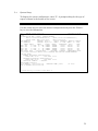
DCB FT-DSU/CSU
Models FT-2DS and FT-4DS
USER'S MANUAL
Data Comm for Business, Inc.
807 Pioneer Street
Champaign, IL 61820
217-352-3207
Rev. Date: August 5, 1996
_______________________
FCC Requirements, Part 15
________________________
This equipment has been tested and found to comply with the limits for a Class A
digital device pursuant to Part 15 of the FCC Rules. These limits are designed to
provide reasonable protection against harmful interference when the equipment is
operated in a commercial environment. This equipment generates, uses, and can
radiate radio frequency energy and if not installed and used in accordance with the
instruction manual may cause harmful interference to radio communications. Operation
of this equipment in a residential area is likely to cause harmful interference, in which
case the user will be required to correct the interference at the user's own expense.
_________________________
FCC Requirements, Part 68
_________________________
This equipment complies with Part 68 of the FCC rules. On the top cover of this
equipment is a label that contains, among other information, the FCC registration
number and ringer equivalence number (REN) for this equipment. If requested, this
information must be provided to the telephone company.
DCB FT-DSU/CSU registration number and REN is as follows:
FCC 68 Registration Number
REN
5QGUSA-23519-DE-N
0.0B
The service code is 6.0N.
The Facility Interface code is as follows,
04DU9-B for lines using the Superframe Format.
04DU9-C for lines using the Extended Superframe Format.
04DU9-S for lines using the B8ZS Format.
DCB FT-DSU/CSU connects to the network using a DA15 connector. A DA15 to RJ48C
conversion cable is included.
iii
If this equipment causes harm to the telephone network, the telephone company will
notify you in advance that temporary discontinuance of service may be required. If
advance notice isn't practical, the telephone company will notify the customer as soon as
possible. Also, you will be advised of your right to file a complaint with the FCC if you
believe it is necessary.
The telephone company may make changes in it's facilities, equipment, operations, or
procedures that could affect the operation of the equipment. If this happens, the
telephone company will provide advance notice in order for you to make the necessary
modifications in order to maintain uninterrupted service.
Normally, this equipment will be used in conjunction with FCC registered equipment
that limits the Encoded Analog Content and provides the required Billing Protection. If
the connected equipment is not of this type, an affidavit must be supplied to the
telephone company where the network connection is to be made. The affidavit is to be
notarized, and is to be filed at least ten days before the initial connection.
If trouble is experienced with this equipment, please contact Data Comm for Business,
Inc., (217) 352-3207 or fax to (217) 352-0350 for repair and warranty information. If the
trouble is causing harm to the telephone network, the telephone company may request
you remove the equipment from the network until the problem is resolved. All repairs
should be handled by authorized Data Comm for Business service personnel.
This equipment cannot be used on telephone company-provided coin service. Connection
to Party Line Service is subject to state tariffs.
iv
_________________________
Safety Requirements
_________________________
CAUTION
•
•
•
•
Never install telephone wiring during a lightning storm.
Never install telephone jacks in wet locations unless the jack is specifically
designed for wet locations.
Never touch bare telephone wires or terminals unless the telephone line has
been disconnected at the network interface.
Use caution when installing or modifying telephone lines.
Refer to the installation section in this manual for a safe and proper installation
procedures. All wiring external to this equipment should follow the current provision of
the National Electrical Code.
___________________________________
National Electrical Code Requirements
___________________________________
The DCB FT-DSU/CSU including this equipment, is ETL certified, and is in compliance
with UL 1459.
v
TABLE OF CONTENTS
SECTION 1 - PRODUCT DESCRIPTION..........................................................3
SECTION 2 - INSTALLATION.............................................................................5
SECTION 3 - OPERATION.................................................................................11
SECTION 4 - FRONT PANEL OPERATION AND INDICATORS...............25
SECTION 5 - SUPERVISOR PORT ..................................................................47
SECTION 6 - INTERFACE SIGNALS AND CABLING..................................61
SECTION 7 - TROUBLESHOOTING ...............................................................67
SECTION 8 - WARRANTY ..................................................................................75
SECTION 9 - GLOSSARY ...................................................................................77
2
1.
PRODUCT DESCRIPTION
1.1
Description
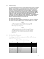
DCB FT is a family of intelligent Fractional T1 Data Service Unit and Channel
Service Unit (DSU/CSU) products as shown in Table 1.1. This product family
provides DS-1 network interface, DS0 channel multiplexing, D&I (Drop and
Insert) functionality, and direct connections to voice, data, and video DTE (Data
Terminal Equipment), as well as T1 channel bank and PBX (Private Branch
Exchanges).
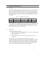
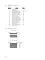
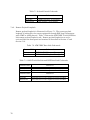
Table 1.1 DCB FT Product Family
Model
Network Interface
Drop and Insert
SNMP
DTE Ports
FT-2DS
FT-4DS
DS-1
DS-1
YES
YES
YES
YES
2
4
DCB FT-DSU/CSU is equipped with local and remote console capability through
an RS232 interface. SNMP (Simplified Network Management Protocol) Proxy
Agent software that resides on a PC DOS platform is available to access the
DCB FT-DSU/CSU from the SNMP Manager.
1.2
Applications
FT-DSU/CSU applications include:
• LAN (Local Area Network) to WAN (Wide Area Network) communications
• Host to workstation communications
• Video conferencing
• Integrated voice and data communication or PBX (Private Branch
Exchanges)
This allows the user to integrate different applications into a single
communication link and utilize only part of available bandwidth, or all 24 DS0
channels. Voice applications may include equipment such as PBXs, Channel
Banks, and Multiplexers. Data and video applications may include equipment
such as video conferencing, bridges, routers, gateways, workstations, host
computers, and various high-speed data terminal equipment.
3
4
2.
INSTALLATION
2.1
Unpacking
This product is shipped in a complete package which contains DCB FT-DSU/CSU
and accessories such as user's manual and DB25 to V.35 or RS449 conversion
cable.
Check the shipping material against Table 2.1 Shipping Material List. Inspect
the unit for any signs of damage. Report any damage to the carrier and contact
DCB or DCB’s customer representative. Retain all packaging material in case
you need to move or ship the unit in the future.
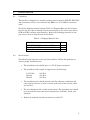
Table 2.1 Shipping Material List
Description
Item
DCB FT-DSU/CSU with 2 or 4 DTE ports
DA-15 to RJ-45 T-1 composite cable
User's Manual
2.2
1
1
1
Site Selection
The following list indicates a site selection guideline. Follow this guideline to
select a proper installation site.
•
The installation site should have a 115V AC power receptacle.
•
The maximum cable length is suggested as the following.
V.35 Cable
RS-449
RS-232
200 Feet
200 Feet
200 Feet
•
The installation site should provide room for adequate ventilation and
cable routing. Reserve at least 5 inches at the rear of the unit for cables
and air flow.
•
The site should provide a stable environment. The operating area should
be clean and free from extremes of temperature, humidity, shock, and
vibration.
•
Relatively humidity should stay between 0 and 95%.
5
2.3
Physical Installation
2.3.1
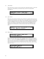
Mechanical
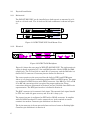
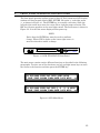
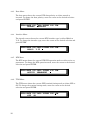
The DCB FT-DSU/CSU can be installed as a desk top unit or mounted in a 19
inch or a 23 inch rack. The 19 inch and 23 inch rackmount is shown in Figure
2.1.
DCB
ES
NET
IN
OUT MON IN
EQU
OUT MON
ACO
Fractional T-1 DSU/CSU
ENT
DCB
ES
NET
IN OUT MON IN
EQU
OUT MON
ACO
Fractional T-1 DSU/CSU
ENT
Figure 2.1 DCB FT-DSU/CSU Rack Mount View
2.3.2
Electrical
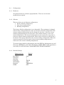
AC 90-230V
ALARM
FUSE RELAY
NC C NO NC C NO
1 2 3
SUPV PORT
EXT CLOCK
DTE4
DTE3
DTE2
DTE1
4 5 6
D&I
LINE
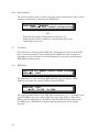
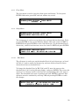
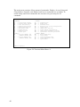
Figure 2.2 DCB FT-4DS Backplane
Figure 2.2 shows the rear panel of DCB FT-4DS DSU/CSU. The right portion is
a plug-in board containing a T1 line and D&I interface labeled LINE and D&I,
respectively. The T1 Line side is a male DA 15 connector, and the D&I side is a
female DA 15 connector. Connector pins are defined in Section 6.
The center portion or the rear panel has the built-in DTE1 and DTE2 ports.
Above it is a plug-in board containing optional DTE3 and DTE4 ports. The ports
are configured as DCE devices with DB 25 connector. One DB 25 to V.35 or DB
25 to RS 449 conversion cable is required for proper application. These
conversion cables are illustrated in Section 6 and are available from DCB or its
representative. The DTE port interface is defined in Section 6.
The BNC connector is for external clock input. The external clock signal should
be TTL level with ±32 ppm accuracy and 40 to 60 % duty cycle.
The supervisor port is configured as DTE with a DE-9P connector. It complies
with the RS232 standard. It can be connected to a local terminal or remote
terminal via modem. Connector pin definition is in Section 6.
The 6 pin connector is for an external alarm such as a buzzer or flashing light.
Connector pin definition is in Section 6.
6
2.4
Configuration
2.4.1
Hardware
All configurations are software programmable. There are no internal
modifications required.
2.4.2
Software
There are three sets of software configuration:
• Factory default configuration
• User stored configuration
• Working configuration
The factory default configuration is not changeable. The equipment is shipped
with all three configurations the same as the factory default configuration. The
current working configuration may be changed at any time. Also, the current
working configuration may be saved into a non-volatile memory as the user
stored configuration. The stored configuration may be retrieved at any time to
reset the current working configuration. Please refer to Section 4 and Section 5
for details. The system memorizes the current working configuration. When the
system is powered off and on again, the previous working configuration is
retrieved as the current working configuration.
To restore factory default configuration, press the ESC key during power up and
then press ENTER key while the LCD displays "SELF TEST". If the operation is
successful, the LCD will show "LOAD DEFAULT CONFIGURATION".
2.4.3
Default Settings
Supervisor Port
Baud Rate
Data Bits
Stop Bits
Parity Bit
XON-XOFF
Interface
SNMP
Default
9600
8
1
NONE
OFF
TERMINAL
OFF
7
T1 Line
Frame Format Mode
Line Code Mode
Line Build Out
Yellow Alarm
Inband Signaling
TABS Address
Idle Code
Drop and Insert Port
Frame Format Mode
Line Code Mode
Equalizer
DTE Port
Rate
Clock
Data
Interface
RTS
TTM
Active Map
MAP1
MAP2
Switch MAP1:
MAP2:
Clock
Master Clock
2nd Clock
External Clock Rate
8
Default
D4
AMI
0 dB
ON
ON
CSU
FF
Default
D4
AMI
0-133 feet
Default
64KxN
NORMAL
NORMAL
RS449
ACTIVE
OFF
Default
all idle
all idle
(00:00 - 12:00)
(12:00 - 00:00)
Default
Line Clock
Line Clock
1.544 Mbps
Alarm Threshold
Alarm Enable
Alarm Relay
Alarm Dial-out
BPV, Line and D&I
ES, Line
UAS, Line
CS, Line
ES, D&I
UAS, D&I
Dial Out
Primary Dial String
Start Time
Stop Time
Secondary Dial String
Start Time
Stop Time
Inactivity Timeout
Misc.
Password
Device Name
LCD-menu-lock
Password lock
SNMP-lock
2.5
Default
Disable
Disable
Disable
10 -5
1
1
1
1
1
Default
ATDT
08:00
07:59
ATDT
08:00
07:59
0 Minutes
Default
DCB
DCB-FT-01
Disable
Disable
Disable
Configuration Checklist
•
Map the telco channels (1-24) to the desired port(s). Section 3.2
•
Set the telco LINE parameters to match your phone line. Section 3.3
•
Set the D&I port parameters if required. Section 3.4
•
Set the DTE port rate to match the telco line rate (56K x N or 64K x N where
N=1-24 channels mapped to that port). Section 3.5
•
Set the DTE port interface to match the attached equipment (RS-449 or
V.35). Section 3.5
9
10
3.
OPERATION
This section describes DCB FT-DSU/CSU configuration options and operational
functions. Refer to Section 4, Front Panel Operation or Section 5, Supervisor Port for
detailed procedures.
3.1
System Operation
3.1.1
Real Time Clock
This product is equipped with a Real Time Clock. The current date and time may
be changed as necessary. The clock battery has a 10 year life. For detailed
operation please refer to Section 4.10 or Section 5.17.
3.1.2
Master Clock
This product has a system clock Phase Lock Loop which may be locked to the:
•
•
•
•
•
T1 line clock
Drop and Insert clock
DTE clock
internal clock
external clock
The T1 line clock, Drop and Insert clock, and internal clock are all 1.544 Mbps.
The DTE clock is either 56KxN, or 64KxN bps (N is 1 to 24 DS-0 channels). The
external clock rate can be 56KxN or 64KxN bps (N is from 1 to 24), 1.544 Mbps,
or 6.176 Mbps. For detailed operation please refer to Section 4.5 or Section 5.16.
The default master and 2nd clock source are T1 line clock. The default external
clock frequency is 1.544 Mbps.
When the master clock source is lost, the system will automatically switch to the
2nd clock source. This is to provide an alternative clock source when the primary
clock source is lost. The current active clock source is shown by the LCD "MCLK"
command and terminal "S" and "C" commands. If a 2nd clock source is not
necessary, the user MUST select the 2nd clock source the same as the master
clock source. When the 2nd clock source is lost as well, the FT-DSU/CSU will
switch to internal clock source automatically. The FT-DSU/CSU will
automatically switch back to the 2nd clock source when it is resumed.
To switch the active clock source from the 2nd clock back to the master clock, the
user MUST toggle the master clock source selection on the front panel "MCLK"
command or terminal "S" command and save the configuration.
11
3.1.3
Supervisor Port
The supervisor port allows the use of a VT-100 terminal, directly or remotely
connected via modem, to configure the system and perform diagnostics, poll
status reports, etc.. The serial port of the terminal must be set to match the
settings of the supervisor port. If necessary, use the Front Panel to setup
supervisor port to utilize local or remote terminal. The supervisor port baud rate,
data bit length, stop bit length, parity bit length, XON-XOFF flow control, and
interface options are shown in Table 3.1. For detailed operation please refer to
Section 5.
Table 3.1 Supervisor Port Settings
Item
Baud Rate
Data Bits
Stop Bits
Parity
XON-XOFF
Interface
SNMP
3.1.4
Options
1200, 2400, 9600, 19200, 38400 bps
8, 7
2, 1
NONE, EVEN, ODD
ON, OFF
TERMINAL, MODEM
ON, OFF
Default
9600
8
1
NONE
OFF
TERMINAL
OFF
Menu Lock and Password
LCD front panel, terminal, as well as SNMP operations are used to read alarms,
system configurations, and system status. Also, these operations may be used to
change system configurations and clear alarm queue, etc.. However, if LCDmenu-lock, password, or SNMP-lock is enabled, only read operations are allowed.
The user may not change system configurations or clear performance data. To
control LCD-menu-lock, password, and SNMP-lock please refer to Section 4.11 or
Section 5.14.
The default option of menu-lock and password is disabled.
The default terminal access password is "DCB".
The default SNMP lock is disabled.
3.1.5
Configuration
Current configurations may be saved into a non-volatile memory. This allows
user to retrieve the last stored configuration. For detailed operation please refer
to Section 4.1 - 4.6 or Section 5.16 - 5.18.
12
3.2
DSO Channel Map
DS0 channel multiplexing is done by the DS0-MAP command. From 1 to 24 DS0
channels can be assigned to any one of the DTE or Drop and Insert ports. Two
maps are available to keep different DS0 channel assignments. A SWITCH
command is available to automatically switch between MAP1 and MAP2 at a
scheduled time. This mode is only available in ESF frame format. The DCB FTDSU/CSU will send the active DS0 maps to the remote side when the SWITCH
command is set and when switch time expires. If the remote side doesn't
respond, the local DCB FT-DSU/CSU alerts a fail message. All unused channels
are idle. An idle code is transmitted on those unused channels. For detailed
operation please refer to Section 4.1 or Section 5.16.
The default active map is MAP1.
The default DS0 channel assignment of both MAP1 and MAP2 are idle channel.
The default switch time is MAP1 (00:00 to 12:00) and MAP2 (12:00 to 00:00).
NOTE
For DS1 network interface with B8ZS coding or all DTE
ports with 56KxN bps, all 24 channels are available for
DS0 multiplexing configuration.
NOTE
For DS1 network interface with AMI coding and DTE ports
with 64KxN bps, only alternate odd or even DS0 channels
should be used. This is required to guarantee one's density
requirement.
3.3
DS1 Network Line Configuration
A detailed option list of T1 line configuration is in Table 3.2. The following
paragraphs describe each item.
Table 3.2 T1 Line Default Settings
Item
Frame Format Mode
Line Code Mode
Line Build Out
Line Equalizer
Yellow Alarm
Inband Signaling
Address
Idle Code
Options
D4, ESF, ESF&T1.403
AMI, B8ZS
0, -7.5, -15 dB
0-133, 133-266, 266-399, 399-533,
533-655 feet
ON, OFF
ON, OFF
CSU, TE
00 ~ FF
Default
D4
AMI
0 dB
0-133 feet
ON
ON
CSU
FF
13
3.3.1
Frame Format Mode
This equipment can be used in T1/D4 and ESF frame format DS1 network
interface. In ESF frame format mode, the user can choose either AT&T or ANSI
facility data link protocol. To set this option, please refer to Section 4.2.1 or
Section 5.16. ESF&T1.403 chooses ANSI ESF data link protocol and one second
performance report will be sent to the network automatically. Also, ANSI and
AT&T data link message is acceptable in ANSI ESF frame format mode.
However, AT&T ESF frame format mode will only accept AT&T ESF data link
protocol.
3.3.2
Line Code Mode
This equipment can be used in AMI (Alternate Mark Inverting) and B8ZS
(Bipolar 8 Zero Substitution) line code format. For detailed operation please refer
to Section 4.2.2 or Section 5.16.
3.3.3
Line Build Out
The T1 line long haul transmit LBO can be programmed to either 0 dB, -7.5 dB,
or -15 dB relative to DSX-1. For detailed operation please refer to Section 4.2.3
or Section 5.16.
3.3.4
Yellow Alarm
DCB FT (DSU/CSU) transmits yellow alarm when LOS (Loss of Signal), AIS
(Alarm Indication Signal), or OOF (Out of Frame) is detected for 2.5 ±0.5
seconds. The user can disable this feature using the disable yellow alarm
command. For detailed operation please refer to Section 4.2.4 or Section 5.16.
3.3.5
Inband Signaling
In T1/D4 framing format and ESF (both AT&T and ANSI data link protocol), an
inband loopback code recognition is used to activate remote loopback operation.
For detailed operation please refer to Section 4.2.5 or Section 5.16.
3.3.6
Address
In T1/ESF framing format, TABS operation requires an address of either CSU
(Channel Service Unit) or TE (Terminal Equipment) identification. For detailed
operation please refer to Section 4.2.6 or Section 5.16.
14
3.3.7
Idle Code
Any DS0 channel which is not assigned to a DTE port or the D&I port is an idle
channel. An idle code is transmitted on idle DS0 channels. The user may
program the idle channel to any bit pattern from 00H to FFh. For detailed
operation please refer to Section 4.2.7 or Section 5.16.
NOTE
Due to the one's density requirement, it is advised that the
idle code to be set to FFh. Otherwise, the user must set the
idle code to contain at least two ‘1’ bits. The factory default
idle code is FFh.
3.4
Drop and Insert Configuration
A detailed option list of T1 Drop and Insert configuration is in Table 3.3. The
following paragraphs describe each item.
Table 3.3 Drop and Insert Default Setting
Item
Frame Format Mode
Line Code Mode
Equalizer
3.4.1
Options
D4, ESF
AMI, B8ZS
0-133, 133-266, 266-399, 399-533,
533-655 feet
Default
D4
AMI
0-133 feet
Frame Format Mode
The Drop and Insert interface can be used in T1/D4 and ESF frame format. To
set this option, please refer to Section 4.3.1 or Section 5.16.
3.4.2
Line Code Mode
The Drop and Insert interface can be used in AMI (Alternate Mark Inverting)
and B8ZS (Bipolar 8 Zero Substitution) line code format. For detailed operation
please refer to Section 4.3.2 or Section 5.16.
15
3.4.3
Equalizer
The Drop and Insert interface transmit equalizer can be programmed to 0 - 133
feet, 133 - 266 feet, 266 - 399 feet, 399 - 533 feet, or 533 - 655 feet. The transmit
signal at the distant end with 100 ohm termination meets the ANSI and AT&T
signal template requirements. To set this option, please refer to Section 4.3.3 or
Section 5.16.
3.5
DTE Configuration
This product is equipped with 2 DTE ports and 2 optional DTE ports may be
added at any time. The system will recognize their existence automatically.
However, all DTE ports must be configured individually for proper operation. A
detailed list of DTE port configuration options is in Table 3.4. The following
paragraphs describe each item.
Table 3.4 DTE Port Default Setting
Item
Rate
Clock
Data
Interface
RTS
TTM
3.5.1
Options
56K, 64KxN (N=1 ~ 24)
NORMAL, INVERTED
NORMAL, INVERTED
RS449, V.35
ACTIVE, PERMANENT
ON, OFF
Default
64KxN
NORMAL
NORMAL
RS449
ACTIVE
OFF
Rate
The DTE ports can operate at 56KxN or 64KxN bps, (N is 1 to 24). Use the Rate
command to select 56K or 64K. Use DS0 MAP command to select number of DS0
channels. For detailed operation please refer to Section4.4.1 or Section 5.16 for
Rate command and Section 4.1 or Section 5.16 for DS0 MAP command.
3.5.2
Clock
Clock polarity of the DTE port is either normal or inverted and is used to drive
the transmit data and to sample the receive data. For detailed operation please
refer to Section 4.4.2 or Section 5.16.
16
3.5.3
Data
Data polarity of a DTE port is either normal or inverted which is used as positive
logic or negative logic. For detailed operation please refer to Section 4.4.3 or
Section 5.16.
3.5.4
Interface
DTE port interface can be either RS449 or V.35. A conversion cable is required
for each DTE port. The user must specify the proper interface type when
ordering. Conversion cables are illustrated in Section 6. To set this option, please
refer to Section 4.4.4 or Section 5.16.
3.5.5
RTS
DTE facility can use RTS (Request To Send) to control transmission. When RTS
is "ACTIVE" and OFF, all ones are sent to the T1 line side on the DTE port
associated DS0 channels. When RTS is "PERMANENT", the RTS signal is
ignored. To set this option, please refer to Section 4.4.5 or Section 5.16.
3.5.6
TTM
Normally the DCB FT uses Transmit Clock to sample DTE Transmit Data. In
terminal timing mode, the DTE facility uses Receive Clock to drive Transmit
Data and loops this clock to the DCB FT via External Clock. And, the DCB FT
will use External Clock to sample Transmit Data instead of using Transmit
Clock. This method is to avoid phase delay due to cable length. In other words, if
the DTE cable is too long, the transmit data may not in-phase with the Transmit
Clock. With this feature, the External Clock and Transmit Data will be in-phase.
To set this option, please refer to Section 4.4.6 or Section 5.16.
3.6
Alarms and Reports
3.6.1
Alarms
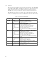
The DCB FT has twenty types of alarms as listed in Table 3.5. Also, DCB FT has
an alarm queue which records the latest 40 alarms with time stamp. DCB FT
also has alarm history and alarm status registers which are used to track the
alarm count. Each alarm can be individually enabled or disabled. When disabled,
no action is taken. When enabled, the alarm counter increments on the
occurrence of the specific type of alarm. When an alarm occurs or the counter
threshold is exceeded, the alarm is triggered.
17
When an alarm is triggered, a dial-out or alarm relay is activated if enabled.
Otherwise, no action is taken and only the specific alarm count is incremented.
Dial-out is to dial out through modem to a remote terminal. Alarm relay is
connected to an external buzzer or flashing signal via the alarm relay connector
as shown in Paragraph 6.1.5. Please refer to Section 5.13 for detailed operation.
When a threshold level is implemented, it is based on the 15 minute alarm count
register.
All alarms default to disabled, dial-out and alarm relay also default to disabled.
Both primary and secondary dial-out strings are Hayes compatible AT dialing
commands. The DCB FT will send the following AT commands to initialize the
modem when modem interface type is selected. The user may add specific
commands in the dialing string to suit their environment.
1.
2.
3.
4.
5.
6.
7.
8.
Auto answer, S0=1.
Ignore DTR signal, &D0.
Track carrier, &C1.
Echo off, E0.
Display result codes in verbose form, V1
Return result code, Q0.
Wait time for carrier 45 sec, S7=45.
Save, &W0 &Y0.
Inactivity timeout can be programmed by the "S" command as in Section 5.16.
After an alarm message is sent, the FT-DSU/CSU waits for the specified number
seconds and then disconnects the modem. If a new alarm is sent during that
period, the timeout counter is reset. Inactivity timeout of 0 seconds will cause
immediate disconnect of the modem after an alarm message is sent.
The alarm counter is updated every 15 minutes. Alarm current status shows the
current state of the associated alarm. The BPV threshold level is a level of error
rate of 10-5 to 10-9.
18
Table 3.5 Alarm Type Table
ALARM TYPE
"MAST-CLK LOSS"
"YEL,LINE"
"AIS,LINE"
"LOS,LINE"
"LOF,LINE"
"BPV,LINE"
"ES,LINE"
"UAS,LINE"
"CS,LINE"
"DTE1 ALARM"
"DTE2 ALARM"
"DTE3 ALARM"
"DTE4 ALARM"
"YEL,D&I"
"AIS,D&I"
"LOS,D&I"
"LOF,D&I"
"BPV,D&I"
"ES,D&I"
"UAS,D&I"
3.6.2
ALARM DESCRIPTION
Master Clock Loss
T1 Line Yellow Alarm
T1 Line Alarm Indication Signal
T1 Line Loss of Signal
T1 Line Loss of Frame
T1 Line Bipolar Violation 10E- (5, 6, 7, 8, 9)
T1 Line Error Second
(0 to 900)
T1 Line Unavailable Second (0 to 900)
T1 Line Control Slip
(0 to 900)
DTE1 RTS loss or clock loss in TTM
DTE2 RTS loss or clock loss in TTM
DTE3 RTS loss or clock loss in TTM
DTE4 RTS loss or clock loss in TTM
D&I Port Yellow Alarm
D&I Port Alarm Indication Signal
D&I Port Loss of Signal
D&I Port Loss of Frame
D&I Port Bipolar Violation 10E- (5, 6, 7, 8, 9)
D&I Port Error Second
(0 to 900)
D&I Port Unavailable Second (0 to 900)
THRESHOLD
no
no
no
no
no
yes (default 5)
yes (default 1)
yes (default 1)
yes (default 1)
no
no
no
no
no
no
no
no
yes (default 5)
yes (default 1)
yes (default 1)
Reports
The DCB FT has four sets of performance registers. These are line, user, D&I,
and far-end. The line performance register tracks the line receiver performance
status. The user performance register tracks the line receiver as well, but the
user may clear this register at any time. The D&I performance register tracks
the D&I port receiver status. The far-end performance register tracks the far-end
receiver status. The performance parameters are listed in Table 3.6. While, the
user performance register and D&I performance register have two additional
parameters. One is a BPV register to count bipolar violations in both D4 and
ESF modes. The other is ESF to track framing and CRC errors in ESF frame
format mode only.
Each performance parameter has 96 sets of register to record 24 hours history in
15 minute intervals.
19
Table 3.6 Performance Report List
Param
Description
Definition (T1/D4)
ES
Error Second
BPV≥1, OOF≥1, or CS≥1.
BES
SES
Bursty Error Second
Severe Error Second
1 < BPV < 1544
BPV ≥ 1544, or OOF ≥ 1
CSS
OOF
Controlled Slip Second
Out of Frame
LOFC
UAS
BPV
ESF
Loss Of Frame Count
Unavailable Second
Bipolar Violation
CRC6 Error, or
Out Of Frame
frame slip ≥ 1
2 frame bit error in 6
consecutive frame bits
OOF for 2.5 ±0.5 sec
≥ 10 consecutive SES
Bipolar Error Count
(not used, always 0)
3.6.3
Definition (ESF)
CRC6 ERROR ≥ 1,
OOF ≥1, or CS ≥1.
1 < CRC 6 < 320
CRC6 ≥ 320, or OOF
≥1
frame slip ≥ 1
2 frame bit error in 6
consecutive frame bits
OOF for 2.5 ±0.5 sec
≥ 10 consecutive SES
Bipolar Error Count
CRC6 error or OOF
Requesting Report
In both T1/D4 and ESF frame format mode, the performance report can be
accessed from a local terminal directly or from remote terminal via modem.
Please refer to Section 5.1 or 5.2 for detailed operation.
Also, in ESF mode, the performance report can be accessed via data link. The
user will choose either AT&T or ANSI T1.403 data link operation in the DS1
network line interface configuration as described in Section 3.3. AT&T TR 54016
should be referred to as how the performance report request message and
response message are structured. ANSI T1.403 should be referred to as how the
one second performance report message is structured.
The DCB FT supports both AT&T TR 54016 and ANSI T1.403 performance
report messages. To set this option, please refer to Section 4.2.1 or Section 5.16.
20
3.7
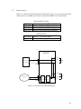
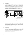
Bantam Jacks
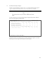
Figure 3.1 shows the block diagram of the bantam jack. It is used to monitor and
isolate fault on the D&I port to detect and isolate D&I facility malfunction.
Break and Test Jacks
NET-IN
NET-OUT
EQU-IN
EQU-OUT
Insert signal toward T1 network
Receive signal from T1 network
Insert signal toward D&I equipment
Receive signal from D&I equipment
Monitor Jacks
NET-MON
EQU-MON
Monitor T1 network signal
Monitor D&I equipment signal
DCB FT
6 MON
Equipment
4 OUT
(E.G.:PBX)
3 IN
EQU
D&I
5 MON
2 OUT
T1 Network
Line
Line
D&I
Framer
Framer
NET
1 IN
Figure 3.1 Bantam Jack Block Diagram
21
3.8
Error Messages
The DCB FT provides various error messages on the LCD display to indicate an
abnormal condition as listed in Table 3.8.
Table 3.8 Error Messages
ERROR CODE
ERROR01
ERROR02
ERROR03
ERROR04
ERROR05
ERROR06
ERROR07
ERROR08
ERROR09
ERROR10
ERROR11
3.9
ERROR DESCRIPTION
A loopback is in effect
ESF or ESF&T1.403 mode is required
D&I isn't mapping to any DS0
DTEn can't be in TTM if MCLK=DTEn
DTEn is in TTM or MCLK=DTEn
Can't change active map of SWITCH
No DS0 channel is assigned
Modem error
A diagnostic test is in progress
DTE local loopback is in progress
SNMP_SLIP mode is in progress
Embedded SNMP Agent
The embedded SNMP agent for the DCB FT offers standard RFC 1213 MIB II
and RFC 1406 DS1 MIB as well as DCB’s enterprise MIB. The Network
manager can use any SNMP compatible network management system such as
SunConnect's SunNetManager and Hewlett-Packard's HP OpenView to monitor
and control the DCB FT. This enables the user to integrate WAN equipment
management with LAN SNMP network management systems. The embedded
SNMP agent also includes Telnet implementation to allow a user to access the
DCB FT terminal interface from any workstation on the network.
SLIP
DCB FT
DCB FT
Async port
WorkStation
SLIP
Terminal Server
Ethernet
Fig 3.2
22
Network Management
System
The DCB FT uses the supervisor port to provide the embedded SNMP agent
functionality. Typically, a workstation can be configured to run SLIP protocol on
its async ports.
Before SNMP is enabled, make sure the IP address for DCB FT is configured
correctly and the communication parameters match the Terminal server port. To
set the IP address, please refer to Section 4.9.7 or Section 5.16.
To enable SNMP agent, please refer to Section 4.9.6 or Section 5.16.
Once the SNMP agent is activated, the user can verify whether the DCB FT is
running successfully by using the ping command to check if DCB FT is
responding or not.
$ ping 192.1.100.45
192.1.100.45 is alive
Please refer to each respective SNMP manager operation instruction to
incorporate the DCB enterprise MIB into the system.
Telnet capability comes with the embedded SNMP agent. Once the SNMP agent
is running, the user can use telnet and a VT100 terminal to access the DCB FT
command screen. The most popular Telnet utility in the public domain is
provided by NCSA. It can maintain several telnet connections simultaneously. It
is recommended to set the COM port at the highest speed to produce a smoother
display of data on the terminal. The DCB FT can run reliably at 38.4 Kbps.
23
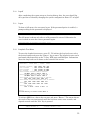
24
4.
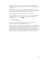
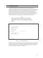
FRONT PANEL OPERATION AND INDICATORS
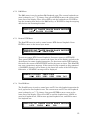
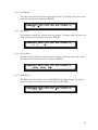
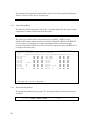
The front panel operation utilizes a two by forty (2 X 40) characters LCD display
window and four keypads labeled ESC, ENTER, left arrow '<', and right arrow
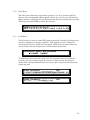
'>', as shown in Figure 4.1. The ENTER key is to enable a selection, while the
left and right arrow keys move the cursor left or right for proper selection. The
ESC key returns operation to the next higher menu. The main menu is shown in
Figure 4.2. It is the first menu displayed after power up.
NOTE
Notice that the ENTER key must be used to confirm a
change. Where YES is shown at the lower right corner, it
must be selected to enable a change.
DCB
ESC
AC
Fractional T-1 DSU/CSU
ENTER
Figure 4.1 DCB FT-DSU/CSU Front Panel
The main menu consists twelve different functions as described in the following
paragraphs. To select one of the functions, use left and right arrow keys to move
the cursor to the function and then press the ENTER key.
<< DS0-MAP LINE D&I DTE1 DTE2 MCLK
CONF TEST ALARM COMM DATE LOCK MISC
>>
<< DS0-MAP LINE D&I DTE-1 -2 -3 -4 MCLK
CONF TEST ALARM COMM DATE LOCK MISC >>
Figure 4.2 LCD Main Menu
25
4.1
DSO-Map Menu
The DS0-Map menu is used to configure DS0 channel assignment for the DTE
and D&I ports. It is also used to program MAP1 and MAP2 as well as to enable
the SWITCH function. DS0 channel assignment can be sent to the remote end
using the SEND command.
4.1.1
Active Menu
The active menu shows the current active MAP (MAP1, MAP2, or SWITCH) by
an '*'. To change the MAP simply move the cursor to the proper MAP or
SWITCH and press ENTER. While SWITCH is selected, the current active map
is shown inside the brackets.
DS0-MAP> ACTIVE MAP1 MAP2 SWITCH
MAP1 MAP2 *SWITCH<MAP1>
SEND
The switch function uses a proprietary ESF data link message, and is only
available in ESF and ESF&T1.403 frame format mode. Otherwise, an error
message (ERROR 2) will be displayed. If the far end facility acknowledges this
command, an "ACK" will be shown on the LCD display. Otherwise, a "FAIL"
message is displayed.
4.1.2
MAP1 / 2 Menu
DS0-MAP>ACTIVE M AP1 MAP2 SWITCH SEND
MAP1>[iiiiiiiiiiiiiiiiiiiiiiii]
The MAP1 menu shows the current assigned ports for each DS0 channel. To
change the designated port, press the ENTER key to a lower layer menu as
follows.
MAP1>[ iiiiiii11ii22ii333i44ddd] CH:01
*IDLE DTE-1 -2 -3 -4 D&I
12: 768K
In the MAP1 menu, “i” indicates idle. The numbers 1, 2, 3, and 4 indicate
corresponding DTE port number, and “d” indicates D&I port. In the above
example, right top corner CH:01 shows the current cursor designated DS0
channel number is 01. And, right lower corner 12: 768K indicates there are 12
idle channels corresponding to 768 Kbps of total 1536 Kbps bandwidth. To
change a specific DS0 channel port assignment, move cursor to a specific DS0
channel which is indicated by the cursor. Press ENTER, the cursor will move to
26
the lower line of the display. The selected port is indicated by an '*'. To change
the port assignment, move the cursor to the desired port and press ENTER. The
Cursor will return to the upper line and the LCD will show the channel number
and bandwidth associated with the designated port.
4.1.3
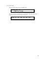
Switch Menu
DS0-MAP>ACTIVE MAP1 MAP2 S WITCH SEND
SWITCH>MAP1 23:00-12:00 MAP2 12:00-23:00
The switch menu shows the current MAP1 and MAP2 schedule as in the above
display. In this case, MAP1 is scheduled start at 23:00 and end at 12:00 and
MAP2 is scheduled start at 12:00 and end at 23:00. To change the schedule press
the ENTER key to a lower layer menu as follows.
SWITCH>MAP1 23:00-12:00 MAP2 12:00-23:00
(H)U D (M)U D-(H)U D (M)U D YES
In the above display “U” indicates up, “D” indicates down, (H) indicates hour and
(M) indicates minute. To change the START time of MAP1, move the cursor to
the left (H) and (M) then select U to increase or D to decrease the START time.
To change the END time of MAP1, move cursor to the right (H) and (M) and do
the same. Notice that MAP2 START and END times are changed concurrently
with the END and START times of MAP1. This operation must be concluded by
selecting YES and pressing ENTER to enable the changes.
4.1.4
Send Menu
Selecting send and pressing ENTER will send the current working DS0 map
information to the far end. This will overwrite the current far end working DS0
map. The send function uses a proprietary ESF data link message, and is only
available in ESF and ESF&T1.403 frame format mode. Otherwise, an error
message (ERROR 2) is displayed. If the far end facility acknowledges this
command, an "ACK" is shown on the LCD display. Otherwise, a "FAIL" message
is displayed.
DSO-MAP>ACTIVE MAP1 MAP2 S WITCH S END
"Send active ds0-map to far-end"
27
4.2
Line Menu
The line menu is used to configure the T1 line parameters such as frame format,
line code, Line Build Out (LBO), yellow alarm transmission when LOF and LOS,
inband loopback code recognition, FDL address code, and transmission idle code.
4.2.1
Frame Format Menu
The following display shows that D4 frame format is selected as indicated by an
'*'. To change the frame type, move the cursor to the desired selection and press
ENTER. ESF&T1.403 indicates ESF frame format is chosen and the facility data
link message follows ANSI T1.403 standard. While ESF indicates ESF frame
format is chosen and the facility data link follows AT&T PUB 54016 standard.
LINE>F RAME CODE LBO YEL INBAND ADDR IDLE
*D4 ESF ESF&T1.403
4.2.2
Code Format Menu
The code format menu shows the current coding scheme by an '*' preceding AMI
or B8ZS. To select the coding scheme, move the cursor to the desired selection
and press ENTER.
LINE>FRAME C ODE LBO YEL INBAND ADDR IDLE
*AMI B8ZS
4.2.3
Line Build Out Menu
The Line Build Out (LBO) menu shows the current transmission LBO is 0, -7.5,
or -15 dB by an '*'. To change the LBO, move the cursor to the desired selection
and press ENTER.
LINE>FRAME CODE L BO YEL INBAND ADDR IDLE
*0.0 -7.5 -15
28
4.2.4
Yellow Menu
The yellow menu shows the current yellow alarm transmission state when loss of
signal and loss of frame synchronous is detected. The current selection is
indicated by an '*'. To enable yellow alarm being automatically sent out upon
loss of signal and loss of frame sync, move the cursor to ON and press ENTER.
To disable transmission, move the cursor to OFF and press ENTER.
LINE>FRAME CODE LBO Y EL INBAND ADDR IDLE
*ON OFF
4.2.5
Inband Menu
The inband menu shows the remote inband loopback diagnostics code
recognition. The current selection is indicated by an '*'. To enable, move the
cursor to ON and press ENTER. To disable, move the cursor to OFF and press
ENTER.
LINE>FRAME CODE LBO YEL I NBAND ADDR IDLE
*ON OFF
4.2.6
Address Menu
The address menu shows the current DCB FT address in FDL is CSU or TE
when ESF frame format mode is selected. The current selection is indicated by
an '*'. To change, move the cursor to the desired option and press ENTER.
LINE>FRAME CODE LBO YEL INBAND A DDR IDLE
*CSU TE
4.2.7
Idle Menu
The idle menu shows the transmission idle code when a DS0 channel is in idle
mode. To change the idle code, press ENTER to the lower line. Then, move the
cursor to ROLL-UP or ROLL-DN to roll up or roll down the idle code. Press
ENTER to select the desired idle code which is shown in the lower left corner of
the display. This operation must be concluded by selecting YES and pressing
ENTER to enable the changes.
29
Note
Due to the one's density requirement, it is advised that the
idle code to be set to FFh. Also, the user must program the
idle code to contain at least two '1' bits. The factory default
is FFh.
LINE>FRAME CODE LBO YEL INBAND ADDR I DLE
=FF
ROLL-UP ROLL-DN YES
4.3
D&I Menu
The D&I menu is used to configure the Drop and Insert port frame format, line
code, and transmission equalizer modes.
4.3.1
Frame Format Menu
The frame format menu shows the current frame format preceded by an '*'. To
change the frame format, move the cursor to the desired selection and press
ENTER.
D&I>F RAME CODE
*D4 ESF
4.3.2
EQU
Line Code Menu
The line code menu shows the current coding scheme preceded by an '*'. To select
the coding scheme, move the cursor to the desired selection and press ENTER.
D&I>FRAME
*AMI
30
C ODE
B8ZS
EQU
4.3.3
Equalizer Menu
The equalizer menu indicates the current transmission equalizer by an '*'. Five
distance ranges are provided from 133 to 655 feet as shown in the lower line of
display. The below display shows that the current selection is 0 to 133 feet. To
change the equalizer, move the cursor to the desired selection and press ENTER.
D&I>FRAME CODE E QU
*0-133 133-266 266-399 399-533 533-655
4.4
DTEn Menu
The DTEn menu is used to configure DTE port operation. Data rate, clock mode,
data mode, interface type, RTS mode, and TTM (Terminal Timing Mode) can be
configured.
4.4.1
Rate Menu
The rate menu indicates the current DTE data rate as either 64KxN or 56KxN
bps by an '*'. To change the data rate, move the cursor to the desired selection
and press ENTER.
DTEn>R ATE CLK DATA INTERF RTS TTM
*64KxN 56KxN
4.4.2
Clock Menu
The clock menu indicates the current DTE clock polarity is either normal or
inverted by an '*'. To change the clock polarity, move the cursor to the desired
selection and press ENTER.
DTEn>RATE C LK DATA INTERF RTS TTM
*NORMAL INVERTED
31
4.4.3
Data Menu
The data menu shows the current DTE data polarity as either normal or
inverted. To change the data polarity, move the cursor to the desired selection
and press ENTER.
DTEn>RATE CLK DATA INTERF RTS TTM
*NORMAL INVERTED
4.4.4
Interface Menu
The interface menu shows the current DTE interface type is either RS449 or
V.35. To change the interface type, move the cursor to the desired selection and
press ENTER.
DTEn>RATE CLK DATA I NTERF RTS TTM
*RS449 V.35
4.4.5
RTS Menu
The RTS menu shows the current DTE RTS operation mode as either active or
permanent. To change the RTS operation mode, move the cursor to the desired
selection and press ENTER.
DTEn>RATE CLK DATA INTERF R TS TTM
*ACTIVE PERMANENT
4.4.6
TTM Menu
The TTM menu shows the current DTE terminal timing mode as either OFF or
ON. To change the terminal timing mode, move the cursor to the desired
selection and press ENTER.
DTEn>RATE CLK DATA INTERF RTS T TM
*OFF ON
32
4.5
Master Clock Menu
The master clock menu is used to configure the master clock source, external
clock source and clock rate.
4.5.1
Master and Second Clock Menu
The master clock menu shows the current clock source is line, internal, D&I,
external, or one of the DTE ports. To change the selection, move the cursor to the
desired selection and press ENTER. The upper right corner shows the current
active clock is M-CLK or 2-CLK.
MCLK>M AST-CLK 2nd-CLK EXTERN-FRQ <2-CLK>
*LINE INTN D&I EXTN DTE-1 -2 -3 -4
4.5.2
External Clock Menu
The external-clock menu shows the current external clock rate at the lower left
corner of the display is 56KxN or 64KxN bps (N is 1 to 24), 1.544 Mbps, or 6.176
Mbps. To change the external clock rate, move the cursor to ROLL-UP or ROLLDN. and press the ENTER key one step at a time. This operation must be
concluded by selecting YES and pressing ENTER to enable the changes.
MCLK>MAST-CLK 2nd-CLK E XTERN-FRQ <2-CLK>
=1.544MBPS
ROLL-UP ROLL-DN YES
4.6
Configuration Menu
The configuration menu is used to store and retrieve system configurations.
4.6.1
Store Menu
The store menu is used to store the current working configuration into the user
stored configuration by pressing ENTER.
CONF>S TORE RETRIEVE
Store current configuration
33
4.6.2
Retrieve Menu
The retrieve menu is used to retrieve the user stored configuration to the current
working configuration by pressing the ENTER key.
CONF>STORE R ETRIEVE
Retrieve last stored configuration
Note
When the user stored configuration is retrieved, all
loopback tests will be terminated, and the alarm queue and
alarm history are reset.
4.7
Test Menu
The test menu is used to perform DTE port, Drop and Insert port, remote DTE
port, and local or remote T1 line loopback tests. QRSS test, and test pattern
selections are also available. If a remote loopback is in session, the front panel
RLB LED is flashing green.
4.7.1
DTE Menu
TEST>D TE D&I RemDTE NearLB RemLB PATTERN
DTE>DTE1 DTE2
The DTE menu is used to perform DTE loopback tests. To initiate a DTE
loopback test, move the cursor to DTE and press ENTER.
DTE> DTE1 DTE2
*OFF TO-DTE
TO-LINE
The current loopback state of the DTE port is indicated by an '*'. To change, first
press ENTER to move the cursor to the lower line of the display. Then select
OFF to end the loopback test, TO-DTE to loop the DTE incoming data back to
the DTE port, or TO-LINE to loop the outgoing data back to the incoming
direction.
34
4.7.2
D&I Menu
The D&I menu is used to perform D&I loopback tests. The current loopback test
state is shown by an '*'. To change, first, press ENTER to move the cursor to the
lower line of the display. Then, select OFF to end the loopback test, TO-DTE to
loop the incoming data back to the D&I facility, or TO-LINE to loop the outgoing
data back to the incoming direction.
TEST>DTE D&I RemDTE NearLB RemLB PATTERN
*OFF TO-DTE TO-LINE
4.7.3
Remote DTE Menu
The RemDTE menu is used to control remote DTE channel loopback. Press
ENTER to move to the lower layer menu.
TEST>DTE D&I RemDTE NearLB RemLB PATTERN
RemDTE>ACTIVATE DEACTIVATE
To activate remote DTE channel loopback, first move cursor to ACTIVATE.
Then, press ENTER to move cursor to the lower line of the display and select the
desired port for remote loopback operation. To deactivate remote DTE loopback,
first move the cursor to DEACTIVATE and do the same as above. This RemDTE
test uses a proprietary message. If the remote facility responds to this command
a "LOOPED" message will be shown in the lower left corner of the LCD display.
Otherwise, a "NOLOOP" message will be displayed.
RemDTE> A CTIVATE
*ALL DTE1
4.7.4
DEACTIVATE
DTE2 DTE3
DTE4
D&I
NearLB Menu
The NearLB menu is used to control near end T1 line side loopback operation for
local, payload or line loopback tests. The current near end T1 line side loopback
state is shown by an '*'. To change, first press ENTER to move cursor to the
lower line of the display. Then select OFF to end the loopback test, LOCAL to
start local loopback test, PLB to start payload loopback test, and LLB to start
line loopback test.
TEST>DTE D&I RemDTE N earLB RemLB PATTERN
*OFF
LOCAL
PLB
LLB
35
4.7.5
RemLB Menu
The RemLB menu is used to activate T1 line remote loopback tests. There are
three remote loopback types, inband, AT&T 54016, and T1.403. Press ENTER to
move to the lower layer menu.
TEST>DTE D&I RemDTE NearLB RemLB PATTERN
RemLB>ACTIVATE DEACTIVATE
To activate remote T1 line loopback, first move cursor to ACTIVATE. Then,
press ENTER to move cursor to the lower line of the display and select the
desired loopback operation. IN-BAND for remote line loopback inband coding,
AT&T-P for remote payload loopback AT&T FDL coding, ANSI-P for remote
payload loopback ANSI FDL coding, or ANSI-L for remote line loopback ANSI
FDL coding. To deactivate remote DTE loopback, move the cursor to
DEACTIVATE and do the same as above.
RemLB> ACTIVATE DEACTIVATE
*IN-BAND AT&T-P ANSI-P
4.7.6
ANSI-L
Pattern Menu
The pattern menu is used to perform QRSS diagnostics and select a variety of
test patterns. Move the cursor to PATTERN and press ENTER to move to the
lower layer menu.
TEST>DTE D&I RemDTE NearLB RemLB P ATTERN
PATTERN>QRSS 3-IN-24 1-IN-8 2-IN-8 1:1
36
4.7.6.1 QRSS Menu
The QRSS menu is used to perform QRSS (Quasi Random Signal Sequence)
tests. The QRSS test channel is selected by a bundle of designated DTE1, DTE2,
DTE3, DTE4, D&I, idle, or all 24 DS0 channels. The current selection is
indicated by an '*'. OFF indicates QRSS test is off. To change, press ENTER to
move the cursor to the lower line of the display. Then move the cursor to the
desired selection and press ENTER. When QRSS is activated, the lower line of
the display shows the results of pattern synchronization, test DTE channel, and
error count.
PATTERN>Q RSS 3-IN-24 1-IN-8 2-IN-8 1:1
*OFF FULL DTE1 DTE2 D&I IDLE
If the received signal is not a QRSS pattern, "QRSS UNSYNC" is shown in the
lower left corner of the LCD display. Otherwise, "QRSS SYNC" is shown and a
bit error count is displayed. The QRSS test port is shown on the LCD display as
well. The User may use '>' key to inject single bit error, '<' key to reset error
counter, and 'ESC' key to quit QRSS testing.
4.7.6.2 Test Pattern Menu
The test pattern is used to transmit on all 24 channels to the T1 line. Four test
patterns, 3-in-24, 1-in-8, 2-in-8, and 1:1 are available. To select, move the cursor
to the desired pattern and press ENTER to move cursor to the lower line of the
display. To activate the pattern, move the cursor to SEND and press ENTER. To
terminate, press the ESC key.
PATTERN>QRSS 3 -IN-24 1-IN-8 2-IN-8 1:1
*OFF SEND
37
4.8
Alarm Menu
The alarm menu is used to view the alarm queue and alarm history, to clear the
alarm queue, alarm history, and alarm relay, as well as to setup alarm
threshold, etc..
ALARM> Q UEUE HISTORY CLEAR SETUP
QUEUE>1 2 3 4 5 6 7 8 9 10(Last 10 alarm
4.8.1
Queue Menu
The queue menu shows the alarm queue of the last 10 alarms. To view any one
of the alarms in the queue, move the cursor to the number and the alarm status
is shown on the lower line of the display. In the following example, the lower left
corner is "AIS,D&I". The first part shows alarm type is AIS (Alarm Indication
Signal), the second part shows where the alarm occurred is D&I (Drop and
Insert) port. On the same line, it shows time and date when the alarm took
place.
QUEUE>1 2 3 4 5 6 7 8 9 10(Last 10 alarm
"AIS,D&I" 18:22:34 03/02/93
4.8.2
History Menu
ALARM>QUEUE HISTORY CLEAR SETUP
HISTROY>NEXT PREVIOUS
The history menu shows alarm history of various types of alarms as defined in
Table 3.5. To view alarm history press ENTER to move to the following display.
Then, move the cursor to NEXT or PREVIOUS and press ENTER to scroll to the
next or previous alarm history. In the following example, "MAST-CLK LOSS"
indicates which alarm is selected, "OK" shows the current status, and "0" is the
total error count.
HISTROY>NEXT P REVIOUS
"MAST-CLK LOSS" OK 0
38
4.8.3
Clear Menu
The clear menu is used to clear the alarm queue and history. To clear press
ENTER. Otherwise, press ESC and exit without any action.
ALARM>QUEUE HISTORY C LEAR SETUP
ALARMS
4.8.4
Setup Menu
ALARM>QUEUE HISTORY CLEAR S ETUP
SETUP>NEXT PREVIOUS EDIT
The setup menu is used to set up alarm relay and auto dial-out functions. To do
so, press ENTER to move to the following display. Move the cursor to NEXT or
PREVIOUS and press ENTER to view each alarm type. To edit threshold level,
alarm relay, and dial-out functions, move the cursor to EDIT and press ENTER.
SETUP>NEXT PREVIOUS EDIT
"MAST-CLK LOSS" EN RELAY-EN DIAL-EN
4.8.4.1 Edit Menu
The edit menu is used to set up the threshold level of each alarm type, as listed
in Table 3.5, and to enable the alarm relay and auto dial-out function. Some
alarms do not have a threshold level.
To change the threshold level of ES, UAS, and CS, move the cursor to the
threshold level, (001) in the following display, and press ENTER. Then, move the
cursor to U to increase and D to decrease the corresponding (100), (10), and (1)
digits. The threshold level count is updated each time ENTER is pressed. This
operation must be concluded by selecting YES and pressing ENTER to enable
the changes.
EDIT>"UAS,D&I" 001 EN RELAY-EN DIAL-EN
(100)U D (10)U D (1)U D YES
39
To change threshold level of BPV, move the cursor to the threshold column and
press ENTER to move the cursor to the lower line of the display. The current
selection is indicated by an '*'. To change, move the cursor to the desired
selection and press ENTER.
EDIT>"BPV,LINE"10E- 5 DI RELAY-DI DIAL-EN
*5 6 7 8 9
EN or DI is to enable or disable the alarm error count. RELAY-EN or RELAY-DI
is to enable or disable the alarm relay when alarm occurs or the error count has
exceeded the threshold level. DIAL-EN or DIAL-DI is to enable or disable the
dial-out function when an alarm occurs or the error count exceeds the threshold
level. To change, press ENTER to move the cursor to the lower line of the
display, then move the cursor to the desired function and press ENTER.
EDIT>"AIS,D&I" EN R ELAY-DI DIAL-EN
*DISABLE ENABLE
4.9
Communication Menu
The communication menu is used to configure the supervisor port data rate, data
bits, stop bits, parity bit, XON-XOFF control, interface type, and SNMP control.
Note
The user MUST use the front panel to set up the supervisor
port properly before connecting a terminal or modem.
4.9.1
Baud Menu
The baud menu indicates the current supervisor port data rate by an '*'. To
change the speed, move the cursor to the desired selection and press ENTER.
COMM>B AUD DATA STOP PAR XON INTERF IP
*38400 19200 9600 2400 1200
40
4.9.2
Data Menu
The data menu shows the current data bit selection. To change, move the cursor
to the desired selection and press ENTER.
COMM>BAUD D ATA STOP PAR XON INTERF IP
*8 7
4.9.3
Stop Menu
The stop menu shows the current stop bits setting. To change stop bits, move the
cursor to the desired selection and press ENTER.
COMM>BAUD DATA S TOP PAR XON INTERF IP
*1 2
4.9.4
Parity Menu
The parity menu shows the current parity setting. To change data parity, move
the cursor to the desired selection and press ENTER.
COMM>BAUD DATA STOP P AR XON INTERF IP
*NONE EVEN ODD
4.9.5
XON Menu
The XON menu shows the current XON-XOFF flow control setting. To change,
move the cursor to the desired selection and press ENTER.
COMM>BAUD DATA STOP PAR X ON INTERF IP
*OFF ON
41
4.9.6
Interface Menu
The interface menu shows the current supervisor port interface type, terminal,
modem, or SNMP. To change, move the cursor to the desired option and press
ENTER. In modem mode, a modem initialization routine is run to establish the
connection. The initialization routine must be run each time the modem is
installed.
COMM>BAUD DATA STOP PAR XON I NTERF IP
*TERMINAL MODEM
Select SNMP-SLIP to enable the embedded SNMP agent operation.
COMM>BAUD DATA STOP PAR XON I NTERF IP
TERMINAL MODEM *SNMP-SLIP
4.9.7
IP Menu
The IP menu allows the user to modify the device IP address and the IP address
used by the SNMP trap message.
COMM>BAUD DATA STOP PAR XON INTERF I P
IP>MY-IP-ADDR TRAP-IP-ADDR
Each IP address can be modified by moving the cursor to each position and
selecting a number. After making all changes, select YES to save the changes.
IP>M Y-IP-ADDR TRAP-IP-ADDR
My IP Address = 192.009.200.010
My IP Address = 1 92.009.200.010
0123456789
42
YES
4.10
Date Menu
The date menu shows the current date and time. Use U to increase and D to
decrease the corresponding (M) for month, (D) for day, (Y) for year, (H) for hour,
(M) for minute, and (S) for second. This operation must be concluded by selecting
YES and pressing ENTER to enable the changes.
DATE>03/16/93 18:30:23
(M)U D(D)U D(Y)U D(H)U D(M)U D(S)U D YES
4.11
Lock Menu
The lock menu is used to control LCD panel operation. Normally, the front panel
provides configuration change capability. This capability can be disabled by
selecting lock menu to disable the front panel. With the front panel locked, the
user can still view the configuration and line status information.
LOCK> front panel and password
*DISABLE ENABLE
To disable the front panel operation lock, the user must enter the password
correctly. Use left or right to pick the character. There are 66 characters to
choose from. Password modification can only be done using a terminal from the
supervisor port.
Enter Password: __________
YES
0123456789ABCDEFGHIJKLMNOPQRSTUVWXYZ!"#$
Enter Password: __________
%&'()*+,-,/:;<=>?@[]^_`{|}
YES
43
4.12
Miscellaneous Menu
4.12.1 Error Code Menu
The error-code menu shows error codes and their description as in the following
example. Table 3.8 lists error codes and their meaning.
MISC>E RROR_CODE PERFRORMANCE STATUS
ERROR_CODE>1 2 3 4 5 6 7 8 9 10 11
ERROR-CODE>1 2 3 4 5 6 7 8 9 10
ERR01:A loopback is in effect
4.12.2 Performance Menu
The performance menu shows the total performance registers of user group and
resets the registers.
MISC>ERROR_CODE
PERF>USER RESET
P ERFRORMANCE STATUS
User performance registers are shown and updated every second.
USER>ES
0
UAS
1
BES
0
SES
0
CS LOFC
0
0
BPV
0
Select reset menu to reset user performance registers. Enter YES to confirm the
action.
PERF>USER R ESET
Clear Performance Data ? YES
44
4.12.3 Status Menu
The status menu shows the line and D&I status.
STATUS>L INE D&I
Show Line Status
The status is shown and updates every second. An ′*′ marks the status. The
following example shows Loss of Signal is detected.
LINE> LOS
*
LOF
RED
YEL
AIS
BPV
45
4.13
Indicators
The front panel has 9 LEDs for operation and error indications. Four DTE LEDs
are for DTE1, DTE2, DTE3, and DTE4 port. D&I is for T1 Drop and Insert port.
LINE is for DS1 network line port. RLB is for Remote Loopback indication.
POWER is for system power indication. ACO is for Alarm Cut-Off indication.
Each LED has three colors, green, amber, and red. The indication is either off,
steady on, or flashing. Table 4.1 lists each LED and its color state and meaning.
Table 4.1 Front-Panel LED Table
LED
POWER
LINE
Meaning
Green
Flashing Green
Red
Off
Flashing Green
Green
Amber
Flashing Amber
Red
Powered on and operational
Software download in progress
Self-Test failure
No T1 line card exists
A line-side loopback is active
T1 line frame synchronous (Normal)
Received yellow alarm from T1 line
Received AIS from T1 line
Loss of Frame Sync (LOFS) or Loss of Signal
(LOS)
D&I port is not assigned any DS0 channel
A D&I loopback is active
D&I frame synchronous (Normal)
Received yellow alarm from D&I port
Received AIS from D&I port
Loss of Frame Sync (LOFS) or Loss of Signal
(LOS)
DTE port is not assigned any DS0 channel
DTE side loopback is active
RTS is asserted to DTE port
DTE port RTS loss or clock loss in TTM
Remote loopback is inactive
Remote loopback is active
Alarm Relay inactive
Alarm Relay active
D&I
Off
Flashing Green
Green
Amber
Flashing Amber
Red
DTE1,2,3,4
Off
Flashing Green
Green
Red
Off
Flashing Green
Off
Red
RLB
ACO
46
Color
5.
SUPERVISOR PORT
The DCB FT-DSU/CSU provides comprehensive report and enhanced
configuration capability through the supervisor port. A VT100 type terminal or a
modem can be connected to the supervisor port on the back of unit. Using singlecharacter commands and arrow keys, the DCB FT can be configured and
monitored. The single-character command is not case sensitive. On each screen,
the available commands and the configurable fields are highlighted. Alarm
messages are also sent to the supervisor port and are shown on the top of the
screen in blinking mode. The main menu is displayed upon power up.
Note
On the upper right corner of the screen, a time-of-day
display indicates the time the current screen was shown.
The user may press any key other than ESC to update the
display.
DCB-FT CSU/DSU V1.5
=== Main Menu ===
[DISPLAY]
1
-> 1-Hour Perf. Report
2
-> 24-Hour Perf. Report
A
-> Line Availability
C
-> DCB-FT System Setup
D
-> DCB-FT Description
E
-> ESF Error Count
H
-> Alarm History
I
-> DCB-FT Status
Q
-> Alarm Queue
[ACCESS]
F
-> Log Off [SETUP] and
[CLEAR & RESET] menu
O
-> Log On [SETUP] and
[CLEAR & RESET] menu
10:50:45 01/11/94
[SETUP]
[CLEAR & RESET]
>>Enter Command ?
Figure 5.1 Terminal Main Menu -1
If the terminal screen is illegible, press "Enter↵" key and "Esc" key alternately to
bring out the main menu. If all efforts fail, check if the right cable is used, and if
the supervisor port parameter setting is matched with the terminal using the
front panel "COMM" command. See Section 4.9.
47
The main menu consists of four groups of commands, Display, Access, Setup and
Clear & Reset. Initially, only Display and Access commands are available. To
enable Setup and Clear commands, the user has to log on using the "O"
command.
DCB-FT CSU/DSU V1.5
=== Main Menu ===
[DISPLAY]
1
-> 1-Hour Perf. Report
2
-> 24-Hour Perf. Report
A
-> Line Availability
C
-> DCB-FT System Setup
D
-> DCB-FT Description
E
-> ESF Error Count
H
-> Alarm History
I
-> DCB-FT Status
Q
-> Alarm Queue
[ACCESS]
F
-> Log Off [SETUP] and
[CLEAR & RESET] menu
O
-> Log On [SETUP] and
[CLEAR & RESET] menu
[SETUP]
L
-> Loopback Test
M
-> Alarm Setup
P
-> Password Setup
R
-> Retrieve Last Stored Configuration
S
-> System Setup
T
-> Change Date and Time
V
-> Store Current Configuration
W
-> Send Active DS0-MAP to Far-end
N
-> Synchronize Far-end System Time
[CLEAR & RESET]
B
-> Reset Alarm Relay
U
-> Clear Alarms
X
-> Clear ESF Error Count
Y
-> Clear Performance Data
Z
-> System Reset
>>Enter Command ?
Figure 5.2 Terminal Main Menu -2
48
10:51:45 01/11/94
5.1
One Hour Performance Report
To show 1 hour performance report, enter "1". A prompt asking for the type of
report is shown at the bottom of the screen. Four choices are available.
>>Select Register Type? *USER
LINE
D&I
FAR-END ( <- , -> , ENTER )
Note
Far-end operation is only accessible in ESF frame format
mode.
Use the cursor keys to select the desired type of report and press the “Enter↵"
key to view the report as shown below.
=== 1-Hour Performance Report ===
10:52:45 01/11/94
USER D4 AMI DS-1
-- Valid Seconds in Current 15-Min Interval : 103 seconds
(ES)
(UAS)
(BES)
(SES) (CSS) (LOFC)
Current 15-Min Interval :
0
0
0
0
0
0
1st Nearest 15-Min Interval :
0
0
0
0
0
0
2nd Nearest 15-Min Interval :
0
0
0
0
0
0
3rd Nearest 15-Min Interval :
0
0
0
0
0
0
4th Nearest 15-Min Interval :
0
0
0
0
0
0
-- Valid 15-Min Intervals in Current 24-Hour Interval : 96
(ES)
(UAS)
(BES)
(SES) (CSS) (LOFC)
Current 24-Hour Interval :
0
0
0
0
0
0
<< Press ESC key to return to Main Menu >>
Second line of the screen shows the type of the performance register set, frame
format type, line code type and line type of current report.
49
5.2
Twenty-Four Hour Performance Report
To show the 24 hour performance report, enter "2". A prompt asking for the type
of report and performance data is shown at the bottom of the screen.
>>Select Register Type? *USER
>>Select Perf Para.? *ES UAS
LINE D&I FAR-END ( <- , -> , ENTER )
BES SES CS LOFC ( <- , -> , ENTER )
Use the cursor keys to select the desired type of report and press the "Enter↵"
key to view the report as shown below.
=== 24-Hour Performance Report ===
10:53:45 01/11/94
USER ES D4 AMI DS-1
-- Valid Seconds in Current 15-Min Interval : 105 seconds
(ES)
(UAS)
(BES)
(SES) (CSS) (LOFC)
Current 15-Min Interval :
0
0
0
0
0
0
-- Valid 15-Min Intervals in Current 24-Hour Interval : 96
(ES)
(UAS)
(BES)
(SES) (CSS) (LOFC)
Current 24-Hour Interval :
0
0
0
0
0
0
-- USER, ES, Last 96 15-Min Interval :
01-08 >
0
0
0
0
0
0
0
0
09-16 >
0
0
0
0
0
0
0
0
17-24 >
0
0
0
0
0
0
0
0
25-32 >
0
0
0
0
0
0
0
0
33-40 >
0
0
0
0
0
0
0
0
41-48 >
0
0
0
0
0
0
0
0
49-56 >
0
0
0
0
0
0
0
0
57-64 >
0
0
0
0
0
0
0
0
65-72 >
0
0
0
0
0
0
0
0
73-80 >
0
0
0
0
0
0
0
0
81-88 >
0
0
0
0
0
0
0
0
89-96 >
0
0
0
0
0
0
0
0
<< Press ESC key to return to Main Menu >>
Second line of the screen shows the type of the performance register set,
performance register, frame format type, line code type and line type of current
report.
5.3
Line Availability
To show the line availability, enter "A". The information, based on user
performance register set, includes the valid seconds, available seconds,
unavailable seconds and the line availability.
=== Line Availability during Last 24-Hour ===
Valid seconds : 86400 seconds
Available Seconds : 86400 seconds
Unavailable Seconds : 0 seconds
Line Availability : 100.0 %
<< Press ESC key to return to Main Menu >>
50
10:54:45 01/11/94
5.4
System Setup
To display the system configuration, enter "C". A prompt asking for the type of
report is shown at the bottom of the screen.
>>Select Type? *LOCAL STORED FAR-END ( <- , -> , ENTER )
Use the cursor keys to select the desired configuration and press the "Enter↵"
key to view the information.
===
DCB-FT System Setup ===
10:55:45 01/11/94
LOCAL
DS0-MAP:ACTIVE MAP = SWITCH CURRENT MAP=MAP1
MAP1=[111122222233444444ddiiii]
MAP2=[111111111111ddddddddiiii]
SWITCH TIME = MAP1 00:00-12:00
MAP2 12:00-00:00
LINE:FRAME=D4
CODE=AMI LBO=0.0
YEL=ON INBAND=ON ADDR=CSU IDLE=FF
D&I :FRAME=D4
CODE=AMI EQU=0-133
<MAP1> 2: 128K <MAP2> 8: 512K
(RATE) <MAP1>
<MAP2>
(CLOCK) (DATA)
(INTERFACE) (RTS)
(TTM)
DTE1: 64K
4: 256K 12: 768K NORMAL
NORMAL
RS449
ACTIVE
OFF
DTE2: 56K
6: 336K
0:
0K NORMAL
NORMAL
RS449
ACTIVE
OFF
DTE3: 64K
2: 128K
0:
0K NORMAL
NORMAL
RS449
ACTIVE
OFF
DTE4: 64K
6: 384K
0:
0K NORMAL
NORMAL
RS449
ACTIVE
OFF
MAST-CLOCK: LINE
2nd-CLK:LINE
EXT-FREQ: 1.544Mbps CURRENT=MAST-CLOCK
RS-232 PORT: BAUD=9600 DATA=8 STOP=1 PAR=NONE XON-XOFF=OFF INTERF=TERMINAL
DIAL-OUT SETUP:
PRIMARY DIALSTRING: ATDT19085551212
START TIME 08:00
STOP TIME 07:59
SECONDARY DIALSTRING: ATDT19085551234
START TIME 08:00
STOP TIME 07:59
INACTIVITY TIMEOUT:
0 MINUTES
DEVICE NAME: DCB-FT-01
MY IP ADDRESS :192.009.200.010
COMMUNITY NAME: public
(12 char)
TRAP IP ADDRESS:255.255.255.255
<< Press ESC key to return to Main Menu >>
51
5.5
System Description
To display the system description, enter "D". A prompt asking for the type of
system description is displayed at the bottom of the screen.
>>Select Type? *LOCAL FAR-END ( <- , -> , ENTER )
Use the cursor keys to select the desired information and press the "Enter↵" key
to view the data.
=== DCB-FT Description ===
LOCAL
Port Configuration : DTE12-D&I-DS1
Serial Number : 2031157
Main Board Version : 1.0
ROM Version : DCB Version 1.3 10/30/93
10:56:45 01/11/94
<< Press ESC key to return to Main Menu >>
5.6
ESF Error Count
To show the ESF error count, enter "E". A prompt asking for the type of report is
displayed at the bottom of the screen.
>>Select Register Type? *USER
LINE
D&I
FAR-END ( <- , -> , ENTER )
Use the cursor keys to select the desired information and press the "Enter↵" key
to view the data.
=== ESF Error Count ===
USER
Start Time : 15:30:58 04/25/93
ESF Errors : 10
<< Press ESC key to return to Main Menu >>
52
10:57:07 01/11/94
5.7
Alarm History
To show the alarm history, enter "H". A prompt asking for the type of alarm
history is displayed at the bottom of the screen.
>>Select Type? *LOCAL FAR-END ( <- , -> , ENTER )
Use the cursor keys to select a desired location and press the "Enter↵" key to
view the data as shown below.
=== Alarm History Report ===
LOCAL Start Time = 10:50:51 10/27/93
(ALARM-TYPE) (THRESHOLD) (CUR-STA)
(COUNT)
MAST-CLK LOSS
OK
0
YEL,LINE
OK
0
AIS,LINE
OK
0
LOS,LINE
OK
0
LOF,LINE
OK
0
BPV,LINE
10E-5
OK
0
ES,LINE
1
OK
0
UAS,LINE
1
OK
0
CS,LINE
1
OK
0
DTE1 ALARM
OK
0
DTE2 ALARM
OK
0
DTE3 ALARM
OK
0
DTE4 ALARM
OK
0
YEL,D&I
OK
0
AIS,D&I
OK
0
LOS,D&I
OK
0
LOF,D&I
OK
0
BPV,D&I
10E-5
OK
0
ES,D&I
1
OK
0
UAS,D&I
1
OK
0
10:56:38 01/11/94
(ALARM)
ENABLE
ENABLE
ENABLE
ENABLE
ENABLE
ENABLE
ENABLE
ENABLE
ENABLE
ENABLE
ENABLE
ENABLE
ENABLE
ENABLE
ENABLE
ENABLE
ENABLE
ENABLE
ENABLE
ENABLE
(RELAY)
ENABLE
ENABLE
ENABLE
ENABLE
ENABLE
ENABLE
ENABLE
ENABLE
ENABLE
ENABLE
ENABLE
ENABLE
ENABLE
ENABLE
ENABLE
ENABLE
ENABLE
ENABLE
ENABLE
ENABLE
(DIALOUT)
ENABLE
ENABLE
ENABLE
ENABLE
ENABLE
ENABLE
ENABLE
ENABLE
ENABLE
ENABLE
ENABLE
ENABLE
ENABLE
ENABLE
ENABLE
ENABLE
ENABLE
ENABLE
ENABLE
ENABLE
<< Press ESC key to return to Main Menu >>
53
5.8
System Status
To display the DCB FT status, enter "I". A prompt asking for the type of system
status report is displayed at the bottom of the screen.
>>Select Type? *LOCAL FAR-END ( <- , -> , ENTER )
Use the cursor keys to select a desired location and press the "Enter↵" key to
view the information.
=== DCB-FT Status Display ===
LOCAL
-- LINE -LOS
: No
LOF
: No
RCV AIS : No
RCV YEL : No
XMT AIS : No
XMT YEL : YES
BPV ERROR COUNT : 1536
ES ERROR COUNT : 2376
-- DTEn -DTE1 RTS LOSS
: No
DTE2 RTS LOSS
: No
DTE3 RTS LOSS
: No
DTE4 RTS LOSS
: No
DTE1 CLOCK LOSS : No
DTE2 CLOCK LOSS : No
DTE3 CLOCK LOSS : No
DTE4 CLOCK LOSS : No
10:58:46 01/11/94
-- D&I -LOS
: No
LOF
: No
RCV AIS : No
RCV YEL : No
XMT AIS : NO
XMT YEL : NO
BPV ERROR COUNT : 0
ES ERROR COUNT : 0
-- TEST -PATTERN TRANSMITTED
QRSS CHANNEL
NEAR-END LOOPBACK
DTE1 LOOPBACK
DTE2 LOOPBACK
DTE3 LOOPBACK
DTE4 LOOPBACK
D&I LOOPBACK
:
:
:
:
:
:
:
:
OFF
OFF
OFF
TO-DTE
OFF
TO-LINE
OFF
TO-LINE
<< Press ESC key to return to Main Menu >>
In the example, the DTE1 port is looping back DTE port signal to DTE, the
DTE3 and D&I ports are looping back the incoming PCM signal to the line.
Yellow alarm is sending out to the line.
5.9
Alarm Queue
To display the alarm queue, enter "Q".
=== Alarm Queue ===
1st nearest alarm -- "LOS,D&I
2nd nearest alarm -- "AIS,LINE
----- Page 1 -----
10:59:12 01/11/94
" 08:13:22 04/29/93
" 11:37:31 04/28/93
<< Press ESC key to return to Main Menu >>
The last 40 alarm entries are shown on the terminal as above in two pages of 20
entries each. If there are more than 20 entries, press any key other than "ESC"
to view the 2nd page. To return to main menu, press the "ESC" key.
54
5.10
Logoff
After completing the system setup or clearing history data, the user should log
off to prevent accidentally changing the system configuration. Enter "F" to logoff.
5.11
Logon
To show a full menu, the user must log on. If the password option is enabled, a
prompt asking for the password is displayed.
==>> Enter Password ?
The full menu is shown only after a valid password is entered. Otherwise the
user is asked to enter the correct password again.
>>Invalid Input of Password ! Try Again ?[y/n]
5.12
Loopback Test Menu
To enter the loopback test menu, enter "L". To initiate the loop back test, select
the desired option and press the "Enter↵" key to start. The loop back tests can be
performed simultaneously on the T1 line, DTE ports and D&I port. Information
about the loop back test is shown at the bottom of the screen,.
=== Loopback Test Menu ===
ARROW KEYS : CURSOR MOVE
-
11:02:12 01/11/94
,
ENTER : SELECT
NEAR-END LOOPBACK : *OFF LOCAL PLB LLB
DTE1 LOOPBACK
: *OFF TO-DTE TO-LINE
DTE2 LOOPBACK
: *OFF TO-DTE TO-LINE
D&I LOOPBACK
: *OFF TO-DTE TO-LINE
SEND LOOPBACK ACTIVATE CODE TO FAR-END :
*IN-BAND AT&T-P ANSI-P ANSI-L
SEND LOOPBACK DEACTIVATE CODE TO FAR-END :
*IN-BAND AT&T-P ANSI-P ANSI-L
SEND CHANNEL LOOPBACK ACTIVE CODE TO FAR-END :
*ALL DTE1 DTE2 DTE3 DTE4 D&I
SEND CHANNEL LOOPBACK DEACTIVATE CODE TO FAR-END :
*ALL DTE1 DTE2 DTE3 DTE4 D&I
SEND QRSS :
*OFF LINE DTE1 DTE2 D&I IDLE
SEND TEST PATTERN :
*OFF 3-IN-24 1-IN-8 2-IN-8 1:1
Status :
<< Press ESC key to return to Main Menu >>
To initiate QRSS test, choose the test port and press "Enter↵". The status shows
the result of the test continuously with the bit error count, error seconds, and
elapsed seconds until the "Esc" key is pressed.
Status :
QRSS SYNC
,CHANNEL=FULL,BIT ERR= 65535
ERROR SECONDS= 20
,ELAPSED SECONDS= 139027
55
To transmit the test pattern continuously, choose one of the 4 patterns and press
"Enter". Press the "Esc" key to stop the test.
Status : "Transmitting 3-in-24 test pattern"
5.13
Alarm Setup Menu
To enter the alarm setup menu, enter "M". A prompt asking for the type of alarm
setup menu is shown at the bottom of the screen.
>>Select Type? *LOCAL FAR-END ( <- , -> , ENTER )
For each type of alarm, three setup choices are available. "ALM" is to set
whether this alarm register counter is enabled or disabled. "DIAL" and "RELAY"
are to activate or deactivate the alarm reporting function. When the alarm
exceeds its threshold, DIAL is to dial out from the supervisor port, and RELAY is
to engage the alarm relay.
=== Local Alarm Setup ===
ARROW KEYS : CURSOR MOVE , TAB : ROLL-UP , ROLL-DOWN
(TYPE)
(THRESHOLD)(ALM)(RELAY)(DIAL)
MAST-CLK LOSS
DIS DIS
DIS
YEL,LINE
EN
EN
EN
AIS,LINE
EN
EN
EN
LOS,LINE
EN
EN
EN
LOF,LINE
EN
EN
EN
BPV,LINE
10E-5
EN
EN
EN
ES,LINE
1
EN
EN
EN
UAS,LINE
1
EN
EN
EN
CS,LINE
1
EN
EN
EN
DTE1 ALARM
EN
EN
EN
11:48:48 01/11/94
(TYPE) (THRESHOLD)(ALM)(RELAY)(DIAL)
DTE2 ALARM
EN
EN
DIS
DTE3 ALARM
EN
EN
EN
DTE4 ALARM
EN
EN
EN
YEL,D&I
EN
EN
EN
AIS,D&I
EN
EN
EN
LOS,D&I
EN
EN
EN
LOF,D&I
EN
EN
EN
BPV,D&I
10E-5
EN
EN
EN
ES,D&I
1
EN
EN
EN
UAS,D&I
1
EN
EN
EN
<< Press ESC key to return to Main Menu >>
5.14
Password Setup Menu
To change the password setup, enter "P". A prompt asking for the desired action
is shown.
=== Password Setup ==
Password ? *DISABLE
56
ENABLE
CHANGE
10:42:58 01/11/94
( <- , -> , ENTER )
To enable the password, select "ENABLE". The previously entered password is
used. The password itself is not case sensitive. If you want to select your own
password, select "CHANGE". Prompts asking for the original password and new
password are shown.
Enter CURRENT Password:
Enter NEW Password:
Re-Enter NEW Password:
5.15
Retrieve Last Stored Configuration
In case configuration changes cause some unexpected effects, enter "R" to restore
the user stored configuration. The system will prompt the following message.
Enter "Y" to retrieve, and "N" to quit.
=>> Retrieve Last Stored Configuration (Y/N)?
5.16
System Setup Menu
Enter "S" to show the system configuration. A prompt asking for the type of
system setup menu may appear at the bottom of the screen.
>>Select Type? *LOCAL FAR-END ( <- , -> , ENTER )
The cursor keys are used to select the field to be changed. As the cursor moves
from field to field, the second line on the screen shows the available input for the
field. After making all the changes, press the "Esc" key and answer yes to make
the changes take effect.
=== Local System Setup ==
10:45:26 01/11/94
DS0-MAP:ACTIVE MAP = MAP1
CH:02
MAP1=[idd111122222233444444iii]
MAP2=[idddddddd111111111111iii]
SWITCH TIME = MAP1 00:00-12:00 MAP2 12:00-00:00
LINE:FRAME=D4
CODE=AMI LBO=0.0
YEL=ON INBAND=ON ADDR=CSU IDLE=FF
D&I :FRAME=D4
CODE=AMI EQU=0-133
<MAP1> 2: 128K <MAP2> 8: 512K
(RATE) <MAP1>
<MAP2>
(CLOCK) (DATA) (INTERFACE) (RTS)
(TTM)
DTE1: 64K
4: 256K 12: 768K NORMAL
NORMAL
RS449
ACTIVE
OFF
DTE2: 64K
6: 384K
0:
0K NORMAL
NORMAL
RS449
ACTIVE
OFF
DTE3: 56K
2: 112K
0:
0K NORMAL
NORMAL
RS449
ACTIVE
OFF
DTE4: 64K
6: 384K
0:
0K NORMAL
NORMAL
RS449
ACTIVE
OFF
MAST-CLOCK: INTERN
2nd-CLOCK:LINE
EXT-FREQ: 1.544Mbps CURRENT=MAST-CLOCK
RS-232 PORT: BAUD=9600 DATA=8 STOP=1 PAR=NONE XON-XOFF=OFF INTERF=TERMINAL
DIAL-OUT SETUP:
PRIMARY DIALSTRING: ATDT
(32 char)
START TIME 08:00
STOP TIME 07:59
SECONDARY DIALSTRING: ATDT
(32 char)
START TIME 08:00
STOP TIME 07:59
INACTIVITY TIMEOUT: 000 MINUTES
DEVICE NAME: DCB-FT-01
(20 char)
MY IP ADDRESS :192.009.200.010
COMMUNITY NAME: public
(12 char)
TRAP IP ADDRESS:255.255.255.255
<< Press ESC key to return to Main Menu >>
57
5.17
Change Date and Time
Enter "T" to change system date and time. The date and time are shown with
the cursor on the hour field. Uses arrow keys to select the field to be changed and
enter the correct information.
22:17:02 05/05/93
( <- , -> : CURSOR MOVE , 0~99 : INPUT )
Press the "Esc" key after making the necessary changes and confirm the
changes with "Y". Input is checked for validation. Invalid information is
discarded and the original value is shown.
>>Save DATE & TIME Setup (Y or N) ?
5.18
Store Current Configuration
Enter "V" to save the working configuration to the user stored configuration so
that it can be retrieved using the "R" command. The system will prompt with the
following message. Enter "Y" to store, and "N" to quit.
=>> Store Current Configuration (Y/N)?
5.19
Send Active DS0 Map to Far-end
Enter "W" to send the current active DS0 map information to the far-end. Since
the notification procedure is implemented in proprietary format, only DCB FT
product family would interpret the message correctly. The unit has to be in ESF
frame format mode to send the active DS0 map to the far-end. An "ACK" or
"FAIL" is displayed depending on whether the far-end unit accepts the DS0 map
or not.
=>> Send Active DS0-MAP to Far-end ...
5.20
ACK
Synchronize Far-end System Time
Enter "N" to synchronize the far-end system time's minutes and seconds. Due to
the time zone difference, the hour is not updated by this command. Since the
notification procedure is implemented in proprietary format, only DCB FT
product family would interpret the message correctly. An "ACK" is shown if the
far-end acknowledges this command; otherwise, a "FAIL" is shown.
=>> Synchronize Far-end System Time .ACK
58
5.21
Reset Alarm Relay
Enter "B" to reset the ACO LED and the alarm relay.
5.22
Clear Alarms
Enter "U" to clear alarm history and queues.
5.23
Clear ESF Error Count
Enter "X" to reset user and D&I ESF error counter. The ESF error count start
time is reset.
5.24
Clear Performance Data
Enter "Y" to reset user and D&I performance registers. This command does not
affect the contents of the performance register set.
5.25
System Reset
Enter "Z" to reset the system without powering down the unit. Upon receiving
this command, the system will restart from the init routine and perform all
power-up diagnostics procedures. The system will prompt with the following
message and the user must enter a valid password to execute this command.
==>> Enter Password ?
59
60
6.
INTERFACE SIGNALS AND CABLING
6.1
Port Interface
6.1.1
DTE Port Interface (DB-25S)
Pin
1
2
3
4
5
6
7
8
9
10
11
12
13
14
15
16
17
18
19
22
24
25
6.1.2
Signal
In/Out
Cable Shield
Transmit Data
Receive Data
Request to Send
Clear to Send
Data Set Ready
Signal Ground
Data Carrier Detect
Receive Clock Return
Data Carrier Detect Return
External Clock Return
Transmit Clock Return
Clear to Send Return
Transmit Data Return
Transmit Clock
Receive Data Return
Receive Clock
Local Loopback
Request to Send Return
Data Set Ready Return
External Clock
Test Mode
----IN
OUT
IN
OUT
OUT
----OUT
OUT
OUT
IN
IN
OUT
Supervisor Port Interface (DE-9P)
Pin
1
2
3
4
5
Signal
Data Carrier Detect
Receive Data
Transmit Data
Data Terminal Ready
Signal Ground
In/Out
IN
IN
OUT
OUT
-----
61
6.1.3
T1 Line Interface (DA-15P)
Pin
1
2
3
4
9
11
6.1.4
1
2
3
4
9
11
62
Transmit Tip
Transmit Ground
Receive Tip
Receive Ground
Transmit Ring
Receive Ring
In/Out
OUT
----IN
----OUT
IN
Drop & Insert Interface (DA-15S)
Pin
6.1.5
Signal
Signal
Transmit Tip
Transmit Ground
Receive Tip
Receive Ground
Transmit Ring
Receive Ring
In/Out
IN
----OUT
----IN
OUT
Alarm Relay Connector
Pin
Signal
1
2
3
4
5
6
Alarm Fuse Normally Closed
Alarm Fuse Common
Alarm Fuse Normally Open
Alarm Relay Normally Closed
Alarm Relay Common
Alarm Relay Normally Open
6.2
Cables
6.2.1
DTE RS-449 Conversion Cable
DB-25P
1
2
3
4
5
6
7
8
9
10
11
12
13
14
15
16
17
18
19
20
22
24
25
6.2.2
Signal
DC37S
Cable Shield
Transmit Data
Receive Data to DTE
RTS (Request to Send)
CTS (Clear to Send)
DSR (Data Set Ready)
Signal Ground
Data Carrier Detect
Receive Clock Return
Data Carrier Detect Return
External Clock Return
Transmit Clock Return
Clear to Send Return
Transmit Data Return
Transmit Clock
Receive Data Return
Receive Clock
Local Loopback
Request to Send Return
Unassigned
Data Set Ready Return
External Clock
Test Mode
1
4
6
7
9
11
19
13
26
31
35
23
27
22
5
24
8
10
25
12
29
17
18
DTE RS-232 Conversion Cable
DB-25P
2
3
4
5
6
7
8
15
17
9,10,12,13,14,16,19,22
Signal
Transmit Data
Receive Data
Request to Send
Clear to Send
Data Set Ready
Signal Ground
Data Carrier Detect
Transmit Clock
Receive Clock
Common to pin 7
DB-25S
2
3
4,20
5
6
7
8
15
17
63
6.2.3
DTE V.35 Conversion Cable
DB-25P
1
2
3
4
5
6
7
8
9
11
12
14
15
16
17
20
24
6.2.4
Signal
M34S
Cable Shield
Transmit Data
Receive Data to DTE
RTS (Request to Send)
CTS (Clear to Send)
DSR (Data Set Ready)
Signal Ground
Data Carrier Detect
Receive Clock Return
External Clock Return
Transmit Clock Return
Transmit Data Return
Transmit Clock
Receive Data Return
Receive Clock
Data Terminal Ready
External Clock
Supervisor Port Cables
To a Terminal
DE-9S
DB-25P
4
2
3
8, 5
7
1
2
3
4
5
To a PC Com Port
64
DE-9S
DE-9S
1
2
3
4
5
4
3
2
1
5
DB-25S
or
or
or
or
or
20
2
3
8
7
A
P
R
C
D
E
B
F
X
W
AA
S
Y
T
V
H
U
To a Modem
DE-9S
DB-25P
8
3
2
4, 20
7
1
2
3
4
5
6.2.5
Line Port to Telco RJ-48C Jack
DA15S
1
2
3
4
9
11
6.2.6
Transmit Tip
Transmit Ground
Receive Tip
Receive Ground
Transmit Ring
Receive Ring
RJ48C
4
1
5
2
D&I Port to Telco RJ-48C Jack
DA15P
1
2
3
4
9
11
6.2.7
Signal
Signal
Transmit Tip
Transmit Ground
Receive Tip
Receive Ground
Transmit Ring
Receive Ring
RJ48C
1
4
2
5
D&I Port to Line Port
DA15P
1
2
3
4
9
11
Signal
Transmit Tip
Transmit Ground
Receive Tip
Receive Ground
Transmit Ring
Receive Ring
DA15S
1
2
3
4
9
11
65
66
7.
TROUBLESHOOTING
7.1
Self Test
At system power up, a complete self-test routine is run to check all I/O ports,
read/write memory, and data paths to validate system integrity. During system
self test, "SELF TEST" is displayed on the upper line of the LCD display. Also,
the software release version and date code are shown on the lower line of the
display. If any error is found, "FAIL" is displayed in the upper right corner of the
display and a dedicated error message is shown on the lower line. Also, the user
may press "ESC", left arrow "<", right arrow ">", and "ENTER" in this order to
read a specific error code. If no error is found, the display will show "PASS" in
the upper right corner followed by a Main Menu as shown in Figure 4.2.
7.2
Diagnostics
A 20-bit Quasi-Random Signal Sequence (QRSS) register is used by the DCB FTDSU/CSU. The QRSS test pattern is used to test the local DCB FT-DSU/CSU
system integrity during local loopback testing. It can also be used to measure the
T1 line quality. The diagnostics scenario is as follows:
1. First, send a remote loopback command to cause the remote facility to
loopback DS0 channels.
2. Then, activate the local QRSS diagnostics operation, use the Test
command to enable QRSS and choose tested DS0 channel in a bundle of
DTE1, DTE2, DTE3, DTE4, D&I, or all 24 channels.
3. When the QRSS pattern sync is found, a bit error counter tracks total bit
errors. It is advised to send QRSS for more than 15 minutes to evaluate
the quality of loop condition and facility reliability.
In both front panel and terminal operation, the user may utilize the '>' key to
inject a single error, the '<' key to reset the error counter, and the 'ESC' key to
terminate the test. The user may also read a performance report to see what
type of errors occurred.
7.3
Near End Loopbacks
The near end loopbacks are local loopback, line loopback, payload loopback, DTE
port loopback, and D&I port loopback. They are activated from the local DCB FT
and are at the near end facility. The following paragraphs describe each loopback
in detail.
67
7.3.1
Local Loopback
Local loopback is illustrated in Figure 7.1. The outgoing signal is looped back
through the T1 PCM transceiver. All 24 DS0 channels are looped back to the
receiver path. This loopback test is activated by the Test command. This
loopback test can be used with the QRSS diagnostic test pattern to validate the
local DCB FT-DSU/CSU’s integrity. An Alarm Indication Signal (AIS) is sent to
the network during local loopback test. Local loopback test can be activated from
the front panel or terminal as described in Section 4.7 and Section 5.12.
DTE Interfaces
T1 Line Interface
DTE
Port
Line
Driver
( V.35/
RS-449)
T1
Multiplexer
PLB
LLB
Line
Receiver
TO-DTE TO-LINE
D&I
Port
Remote Channel Loopback
Link
Local
Loopback
Remote Payload Loopback
Remote Line Loopback
PLB: Payload Loopback
LLB: Line Loopback
Figure 7.1 Loopback Block Diagram
7.3.2
Line Loopback
Line loopback is illustrated in Figure 7.1. The incoming T1 line signal is looped
back to the outgoing T1 signal before the T1 transceiver framer. This loopback is
used to isolate the local equipment from a troubled T1 transmission line. Line
loopback test can be activated from the front panel or terminal as described in
Section 4.7 and Section 5.12.
7.3.3
Payload Loopback
Payload loopback is illustrated in Figure 7.1. The incoming signal is looped back
to the outgoing T1 signal after the T1 transceiver framer. This loopback is used
to isolate the DTE ports and D&I port from the troubled T1 transmission line.
Payload loopback test can be activated from the front panel or terminal as
described in Section 4.7 and Section 5.12.
68
7.3.4
DTE Port Loopback
DTE port loopback is illustrated in Figure 7.1. There are two types of DTE
loopback, TO-DTE and TO-LINE. The TO-DTE loopback loops toward the DTE
port. The TO-LINE loopback loops toward the T1 network interface. This
loopback is used to validate the system integrity of the DTE facility. DTE
loopback tests can be activated from the front panel or terminal as described in
Section 4.7 and Section 5.12. While in TO-DTE loopback, all ones are sent to the
T1 network line on DTE associated DS0 channels.
7.3.5
D&I Port Loopback
D&I port loopback is illustrated in Figure 7.1. There are two types of D&I
loopback, TO-DTE and TO-LINE. The TO-DTE loopback loops toward the D&I
port. The TO-LINE loopback loops toward the T1 netowrk interface. This
loopback is used to validate the system integrity of the D&I facility. Drop and
Insert loopback test can be activated from the front panel or terminal as
described in Section 4.7 and Section 5.12.
7.4
Far End Loopback
The far end loopbacks are remote line loopback, remote payload loopback, and
remote channel loopback. The remote facility utilizes inband coding and FDL
Facility Data Link to initiate the loopback. It is advised that remote loopbacks
be used in conjunction with QRSS diagnostics test to measure the T1 network
line quality. The procedure is as follows:
1. First, send a remote loopback command to cause the remote facility to
loop back some DS0 channels.
2. Then, activate the QRSS diagnostics operation by QRSS command as in
Section 7.5.2.
The following paragraphs describe each type of remote loopback.
7.4.1
Remote Line Loopback
Remote line loopback is illustrated in Figure 7.1. The remote line loopback is
initiated by the remote equipment through inband signaling or ESF data link
message with AT&T or ANSI protocol. Table 7.1 shows the inband remote line
loopback code. Table 7.3 shows the ANSI T1.403 ESF data link remote line
loopback code. Remote line loopback test can be activated from the front panel
and terminal as described in Section 4.7 and Section 5.12.
69
Table 7.1 In-band Control Codewords
Remote LLB
Activate
Deactivate
7.4.2
Codeword
10000, receive 5 ±0.5 second
100, receive 5 ±0.5 second
Remote Payload Loopback
Remote payload loopback is illustrated in Figure 7.1. The remote payload
loopback is initiated by the remote equipment through ESF data link message
with AT&T or ANSI protocol. Table 7.2 shows the AT&T ESF T1.403 ESF data
link remote payload loopback code. Remote payload loopback test can be
activated from the front panel and terminal as described in Section 4.7 and
Section 5.12.
Table 7.2 AT&T ESF Data-Link Codewords
Remote PLB
Activate
Deactivate
Codeword
ESF-DL SX.25 Reuqest Message #1
ESF-DL SX.25 Request Message #2
Table 7.3 ANSI T1.403 Bit-Oriented ESF Data-Link Codewords
Remote LLB
Activate
Deactivate
Remote PLB
Activate
Deactivate
70
Codeword
0 000111 011111111 repeat at least 10 times
0 011100 011111111 repeat at least 10 times
Codeword
0 001010 011111111 repeat at least 10 times
0 011001 011111111 repeat at least 10 times
7.4.3
Remote Channel Loopback
Remote channel loopback is illustrated in Figure 7.1. The remote channel
loopback is initiated by the local equipment through following methods:
1) In-band remote channel loopback code.
In-band activate and deactivate codes are used to enable and disable DTE
to a TO-LINE loopback. This loopback provides an unique way to isolate
problems of a specific data path from T1 network line toward remote
DTE.
Activate code, 11110111 rotate left in 10 Hz for 5 ±0.5 sec.
Deactivate code, 11011011 rotate left in 10 Hz for 5 ±0.5 sec.
2) ESF and ESF&T1.403 facility data link remote channel loopback code.
A proprietary protocol in the ESF facility data link is used to enable and
disable remote DTE port to perform TO-LINE loopback. This loopback
provides an unique way to isolate problems of a specific data path from
T1 network line toward remote DTE port.
The remote channel loopback command uses ESF data link message. The ESF
data link message to activate request and response are in Table 7.4 and Table
7.5 and the data link message to deactivate request and response are listed in
Table 7.6 and Table 7.7.
Table 7.4 Remote Channel Loopback Activate Request Messages
Octet No.
1
2
3
4
5~28
Label
Command #
Originate Unit Add
Target Unit Add
Request#
DS0~DS23
Contents
0 to 255
(A or Z) or (B or Y)
(A or Z) or (B or Y)
249
0: no action.
1: DTE1 activate loopback
2: DTE2 activate loopback
3: DTE3 activate loopback
4: DTE4 activate loopback
5: D&I activate loopback
71
Table 7.5 Remote Channel Loopback Activate Response Messages
Octet No.
1
2
3
4
5
Label
Command #
Status
Originate Unit Add
Target Unit Add
Current Status
Contents
0 to 255
0000U000
(A or Z) or (B or Y)
(A or Z) or (B or Y)
FU0000L0
NOTE
F=1, if U or L=1
U=1,if an unavailable signal state exists
L=1, if the PLB is activated
0(reserved)
Table 7.6 Remote Channel Loopback Deactivate Request Messages
Octet No.
1
2
3
4
5~28
72
Label
Command #
Originate Unit Add
Target Unit Add
Request#
DS0~DS23
Contents
0 to 255
(A or Z) or (B or Y)
(A or Z) or (B or Y)
249
0: no action.
1: DTE1 activate loopback
2: DTE2 activate loopback
3: DTE3 activate loopback
4: DTE4 activate loopback
5: D&I activate loopback
Table 7.7 Remote Channel Loopback Deactivate Response Messages
Octet No.
1
2
3
4
5
Label
Command #
Status
Originate Unit Add
Target Unit Add
Current Status
Contents
0 to 255
0000U000
(A or Z) or (B or Y)
(A or Z) or (B or Y)
FU0000L0
NOTE
F=1, if U or L=1.
U=1,if an unavailable signal state exists,
L=1, if the PLB is activated.
0(reserved)
7.5
Test Pattern
Four test patterns are available to determine faults such as deficient clock
recovery, faulty ALBO level recovery, inadequate jitter margin, presence of
bridge taps, and mis-optioned network interface. These four patterns are framed
patterns with proper D4 or ESF frame pattern as described in the following
paragraphs.
7.5.1
3-in-24 Pattern
This framed 3-in-24 pattern is aligned with the frame bit so as not to transmit a
false yellow alarm. It tests the consecutive zeros requirement and is useful to
test AMI circuits.
Framed 3-in-24 pattern sequence is as follows,
F 01000100 00000000 00000100 01000 . . . . . (Left to Right)
F indicates frame bit.
73
7.5.2
1-in-8 Pattern
This framed 1-in-8 pattern tests the ability of a circuit to support a pattern
having the minimum ones density. It is useful to reveal a timing recovery
problem. The bit set to one must be set to bit 2 to avoid a false yellow alarm.
Framed 1-in-8 pattern sequence is as follows,
F 01000000 01000000 0100 . . . . . (Left to Right)
F indicates frame bit.
7.5.3
2-in-8 Pattern
This framed 2-in-8 pattern, in conjunction with the 1-in-8 Pattern, is useful
when performing tests to reveal the presence of equipment mis-optioned for
B8ZS. Use of 2-in-8 pattern will confirm the circuit's ability to support error free
transmission when B8ZS substitutions do not occur. A framed 1-in-8 will contain
8 consecutive zeros around a zero frame bit causing a B8ZS substitution.
Framed 2-in-8 pattern sequence is as follows,
F 01000010 01000010 01 . . . . (Left to Right)
F indicates frame bit.
7.5.4
1:1 Pattern
This framed 1:1 pattern tests AMI circuits. It will cause false yellow alarms in
D4 frame format mode.
Framed 1:1 pattern sequence is as follows,
F 10101010 10101010 10 . . . . . (Left to Right)
F indicates frame bit.
74
8.
WARRANTY
All DCB products are warranted to be free of defects in materials and
workmanship for one year. Data Comm for Business, Inc. will repair or replace
any equipment proven to be defective within the warranty period. All
warranty work is F.O.B. Champaign, IL. This warranty is exclusive of abuse,
misuse, accidental damage, acts of God or consequential damages, etc. DCB
liability shall not exceed the original purchase price.
All equipment returned for warranty repair must be accompanied by a
Returned Material Authorization (RMA) number. To receive an RMA number,
call (217) 352-3207 between the hours of 8 AM and 5 PM central time.
Equipment must be shipped prepaid to DCB and will be returned at DCB's
expense.
Data Comm for Business, Inc.
807 Pioneer Street
Champaign, IL 61820
Voice (217) 352-3207
Fax
(217) 352-0350
Email [email protected]
75
76
9.
GLOSSARY of TERMS
A
AIS
Alarm Indication Signal
AMI Alternate Mark Inverting
ANSI American National Standards Institute
B
B8ZS Bipolar 8 Zero Substitution
CSU
CTS
C
Channel Service Unit
Clear to Send
D
D&I Drop and Insert
DACS Digital Access Cross-Connect System
DSR Data Set Ready
DSU Data Service Unit
DTE Data Terminal Equipment
DTR Data Terminal Ready
ES
ESF
E
Errored Seconds
Extended Super Frame
LAN
LBO
LLB
LOFS
LOS
L
Local Area Network
Line Build Out
Line Loopback
Loss of Frame Sync
Loss of Signal
NI
N
Network Interface
OOF
Out of Frame
PBX
PLB
PLL
P
Private Branch Exchanges
Payload Loopback
Phase Lock Loop
RTC
RTS
Real Time Clock
Request to Send
R
S
SNMP Simplified Network Management Protocol
T
TE
Terminal Equipment
TTM Terminal Timing Mode
W
WAN Wide Area Network
O
Q
QRSS Quasi-Random Signal Sequence
77