1
CNC
C6/C64
SPECIFICATIONS MANUAL
BNP-B2266C(ENG)
MELDAS and MELSEC are registered trademarks of Mitsubishi Electric Corporation.
Other company and product names that appear in this manual are trademarks or registered trademarks of
the respective company.
Introduction
This manual describes the specifications of MELDAS C6/C64.
To safely use this CNC unit, thoroughly study the "Precautions for Safety" on the next
page before use.
Details described in this manual
At the beginning of each item, a table indicating it’s specification according to the model.
{
∆
: Standard
: Option
: Selection
: Special option
CAUTION
The items that are not described in this manual must be interpreted as "not
possible".
This manual is written on the assumption that all option functions are added.
Some functions may differ or some functions may not be usable depending on the
NC system (software) version.
General precautions
(1) When the contents of this manual is updated, the version (*, A, B, …) on the cover
will be incremented.
Precautions for Safety
Always read the specifications issued by the machine maker, this manual, related manuals and
attached documents before installation, operation, programming, maintenance or inspection to
ensure correct use.
Understand this numerical controller, safety items and cautions before using the unit.
This manual ranks the safety precautions into "DANGER", "WARNING" and "CAUTION".
DANGER
When there is a great risk that the user could be subject to
fatalities or serious injuries if handling is mistaken.
WARNING
When the user could be subject to fatalities or serious injuries
if handling is mistaken.
CAUTION
When the user could be subject to injuries or when physical
damage could occur if handling is mistaken.
Note that even items ranked as "
CAUTION", may lead to major results depending on the
situation. In any case, important information that must always be observed is described.
DANGER
Not applicable in this manual.
WARNING
Not applicable in this manual.
CAUTION
1. Items related to product and manual
The items that are not described in this manual must be interpreted as "not possible".
This manual is written on the assumption that all option functions are added.
Some functions may differ or some functions may not be usable depending on the NC
system (software) version.
2. Items related to start up and maintenance
Follow the power specifications (input voltage range, frequency range, momentary
power failure time range) described in this manual.
Follow the environment conditions (ambient temperature, humidity, vibration,
atmosphere) described in this manual.
!
Follow the remote type machine contact input/output interface described in this manual.
(Connect a diode in parallel with the inductive load or connect a protective resistor in
serial with the capacitive load, etc.)
If the parameter is used to set the temperature rise detection function to invalid,
overheating may occur, thereby disabling control and possibly resulting in the axes
running out of control, which in turn may result in machine damage and/or bodily injury
or destruction of the unit. It is for this reason that the detection function is normally left
"valid" for operation.
CONTENTS
1. Control Axes.......................................................................................................................
1.1 Control Axes.................................................................................................................
1.1.1 Number of Basic Control Axes (NC axes) ..........................................................
1.1.2 Max. Number of Control Axes
(NC axes + Spindles + PLC axes + Auxiliary axes) ...........................................
1.1.3 Number of Simultaneous Contouring Control Axes............................................
1.1.4 Max. Number of NC Axes in a Part System .......................................................
1.2 Control Part System.....................................................................................................
1.2.1 Standard Number of Part Systems .....................................................................
1.2.2 Max. Number of Part Systems ............................................................................
1.3 Control Axes and Operation Modes ............................................................................
1.3.2 Memory Mode .....................................................................................................
1.3.3 MDI Mode............................................................................................................
1
1
1
2. Input Command .................................................................................................................
2.1 Data Increment ............................................................................................................
2.2 Unit System..................................................................................................................
2.2.1 Inch/Metric Changeover; G20/G21 .....................................................................
2.3 Program Format...........................................................................................................
2.3.1 Character Code...................................................................................................
2.3.2 Program Format ..................................................................................................
2.3.2.1 Format 1 for Lathe (G code list 2, 3) ......................................................
2.3.2.4 Format 1 for Machining Center (G code list 1).......................................
2.4 Command Value ..........................................................................................................
2.4.1 Decimal Point Input I, II .......................................................................................
2.4.2 Absolute / Incremental Command; G90/G91 .....................................................
2.4.3 Diameter/Radius Designation .............................................................................
2.5 Command Value and Setting Value Range ................................................................
2.5.1 Command Value and Setting Value Range........................................................
4
4
5
5
6
6
7
7
7
8
8
9
11
12
12
3. Positioning/Interpolation ..................................................................................................
3.1 Positioning; G0, G60....................................................................................................
3.1.1 Positioning; G0....................................................................................................
3.1.2 Unidirectional Positioning; G60...........................................................................
3.2 Linear/Circular Interpolation; G1, G2/G3 .....................................................................
3.2.1 Linear Interpolation; G1.......................................................................................
3.2.2 Circular Interpolation (Center/Radius Designation); G2/G3 ...............................
3.2.3 Helical Interpolation.............................................................................................
16
16
16
17
18
18
19
21
4. Feed.....................................................................................................................................
4.1 Feed Rate ....................................................................................................................
4.1.1 Rapid Traverse Rate (m/min)..............................................................................
4.1.2 Cutting Feed Rate (m/min)..................................................................................
4.1.3 Manual Feed Rate (m/min) .................................................................................
4.2 Feed Rate Input Methods; G94/G95 ...........................................................................
4.2.1 Feed per Minute ..................................................................................................
4.2.2 Feed per Revolution............................................................................................
4.2.4 F1-digit Feed .......................................................................................................
4.3 Override .......................................................................................................................
4.3.1 Rapid Traverse Override.....................................................................................
4.3.2 Cutting Feed Override.........................................................................................
4.3.3 2nd Cutting Feed Override..................................................................................
4.3.4 Override Cancel ..................................................................................................
23
23
23
24
25
26
26
28
29
30
30
30
30
31
i
1
2
2
2
2
2
3
3
3
4.4 Acceleration/Deceleration............................................................................................
4.4.1 Automatic Acceleration/Deceleration after Interpolation ....................................
4.4.2 Rapid Traverse Constant Inclination Acceleration/Deceleration........................
4.5 Thread Cutting .............................................................................................................
4.5.1 Thread Cutting (Lead/Thread Number Designation); G33 .................................
4.5.2 Variable Lead Thread Cutting; G34 ....................................................................
4.5.3 Synchronous Tapping; G74, G84 .......................................................................
4.5.3.1 Synchronous Tapping Cycle ..................................................................
4.5.4 Chamfering..........................................................................................................
4.6 Manual Feed ................................................................................................................
4.6.1 Manual Rapid Traverse.......................................................................................
4.6.2 Jog Feed .............................................................................................................
4.6.3 Incremental Feed ................................................................................................
4.6.4 Handle Feed........................................................................................................
4.7 Dwell; G04....................................................................................................................
4.7.1 Dwell (Time-based Designation).........................................................................
32
32
33
36
36
38
39
39
40
41
41
41
42
42
43
43
5. Program Memory/Editing..................................................................................................
5.1 Memory Capacity .........................................................................................................
5.1.1 Memory Capacity (Number of Programs Stored) ...............................................
5.2 Editing Method .............................................................................................................
5.2.1 Program Editing ..................................................................................................
5.2.2 Background Editing.............................................................................................
44
44
44
45
45
46
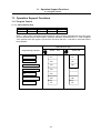
6. Operation and Display.......................................................................................................
6.1 Structure of Operation/Display Panel ..........................................................................
6.2 Operation Methods and Functions ..............................................................................
6.2.1 Memory Switch (PLC Switch) .............................................................................
6.3 Display Methods and Contents....................................................................................
6.3.1 Status Display .....................................................................................................
6.3.2 Position Display...................................................................................................
6.3.3 Program Running Status Display........................................................................
6.3.4 Setting and Display .............................................................................................
6.3.5 MDI Data Setting and Display.............................................................................
6.3.7 Clock ...................................................................................................................
6.3.8 Hardware/Software Configuration Display..........................................................
6.3.9 Integrated Time Display ......................................................................................
6.3.10 Available Languages (Japanese/English) ........................................................
6.3.11 Additional Languages (Japanese/English/Polish) ............................................
6.3.11.1 Japanese ..............................................................................................
6.3.11.2 English..................................................................................................
6.3.11.13 Polish..................................................................................................
6.3.13 Screen Deletion.................................................................................................
6.4 Display Unit Switch .....................................................................................................
6.4.1 Single-NC and Multi-Display Unit Switch...........................................................
6.4.2 Multi-NC and Common-Display Unit..................................................................
6.4.4 Multi-NC and Common-external PC Display .....................................................
6.4.5 Display Unit Detachable.....................................................................................
47
47
48
48
48
48
49
50
50
50
50
50
51
52
52
52
52
52
52
53
53
53
53
54
7. Input/Output Functions and Devices...............................................................................
7.1 Input/Output Data.........................................................................................................
7.2 Input/Output I/F ............................................................................................................
7.2.1 RS-232C I/F ........................................................................................................
7.2.2 IC Card I/F...........................................................................................................
7.2.2.1 I/F for IC Card in Control Unit.................................................................
55
55
56
56
56
56
ii
8. Spindle, Tool and Miscellaneous Functions ..................................................................
8.1 Spindle Functions (S)...................................................................................................
8.1.1 Command/Output................................................................................................
8.1.1.1 Spindle Functions...................................................................................
8.1.1.2 Spindle Serial I/F ....................................................................................
8.1.1.3 Spindle Analog I/F ..................................................................................
8.1.1.4 Coil Change............................................................................................
8.1.1.5 Automatic Coil Change...........................................................................
8.1.2 Speed Control .....................................................................................................
8.1.2.1 Constant Surface Speed Control ...........................................................
8.1.2.2 Spindle Override.....................................................................................
8.1.2.3 Multiple-spindle Control..........................................................................
8.1.2.3.1 Multiple-spindle Control I.....................................................
8.1.3 Position Control...................................................................................................
8.1.3.1 Spindle Orientation.................................................................................
8.1.3.3 Spindle Synchronization.........................................................................
8.1.3.3.1 Spindle Synchronization I .......................................................
8.1.3.3.2 Spindle Synchronization II ......................................................
8.2 Tool Functions (T)........................................................................................................
8.2.1 Tool Functions.....................................................................................................
8.3 Miscellaneous Functions (M).......................................................................................
8.3.1 Miscellaneous Functions.....................................................................................
8.3.2 Multiple M Codes in 1 Block................................................................................
8.3.3 M Code Independent Output ..............................................................................
8.3.4 Miscellaneous Function Finish............................................................................
8.3.5 M Code Output during Axis Positioning..............................................................
8.4 2nd Miscellaneous Function (B) ..................................................................................
8.4.1 2nd Miscellaneous Function ...............................................................................
57
57
57
57
58
58
58
58
59
59
60
60
61
62
62
63
63
64
65
65
66
66
66
67
67
68
69
69
9. Tool Compensation ...........................................................................................................
9.1 Tool Length/Position Offset; G43 to G49 ....................................................................
9.1.1 Tool Length Offset...............................................................................................
9.1.3 Tool Offset for Additional Axes ...........................................................................
9.2 Tool Radius; G38 to G42, G46 ....................................................................................
9.2.1 Tool radius Compensation; G38 to G42 .............................................................
9.2.3 Tool Nose Radius Compensation (G40/41/42) ..................................................
9.2.4 Automatic Decision of Nose Radius Compensation Direction (G46/40)............
9.3 Tool Offset Amount ......................................................................................................
9.3.1 Number of Tool Offset Sets ................................................................................
9.3.1.2 40 sets ...................................................................................................
9.3.1.3 80 sets ...................................................................................................
9.3.1.4 100 sets .................................................................................................
9.3.1.5 200 sets .................................................................................................
9.3.2 Offset Memory.....................................................................................................
9.3.2.1 Tool Shape/Wear Offset Amount ...........................................................
70
70
70
72
73
73
75
76
77
77
77
77
77
77
78
78
10. Coordinate System.....................................................................................................
10.1 Coordinate System Type and Setting; G52 to G59, G92..........................................
10.1.1 Machine Coordinate System; G53....................................................................
10.1.2 Coordinate System Setting; G92 ......................................................................
10.1.3 Automatic Coordinate System Setting..............................................................
10.1.4 Workpiece Coordinate System Selection (6 sets); G54 to G59 .......................
10.1.5 Extended Workpiece Coordinates System Selection.......................................
10.1.7 Local Coordinate System; G54G52 to G59G52 ...............................................
10.1.8 Coordinate System for Rotary Axis...................................................................
81
81
82
83
84
85
86
87
88
iii
10.1.9 Plane Selection; G17 to G19 ............................................................................
10.1.10 Origin Set ........................................................................................................
10.1.11 Counter Set .....................................................................................................
10.2 Return; G27 to G30....................................................................................................
10.2.1 Manual Reference Point Return .......................................................................
10.2.2 Automatic 1st Reference Point Return; G28, G29 ...........................................
10.2.3 2nd, 3rd, 4th Reference Point Return; G30 ......................................................
10.2.4 Reference Point Verification; G27 ....................................................................
10.2.5 Absolute position detection ...............................................................................
10.2.6 Tool Exchange Point Return; G30.1 to G30.6..................................................
88
89
89
90
90
91
93
94
95
96
11. Operation Support Functions ...................................................................................
11.1 Program Control.........................................................................................................
11.1.1 Optional Block Skip...........................................................................................
11.1.3 Single Block ......................................................................................................
11.2 Program Test .............................................................................................................
11.2.1 Dry Run .............................................................................................................
11.2.2 Machine Lock ....................................................................................................
11.2.3 Miscellaneous Function Lock............................................................................
11.3 Program Search/Start/Stop........................................................................................
11.3.1 Program Search ................................................................................................
11.3.2 Sequence Number Search ...............................................................................
11.3.5 Automatic Operation Start.................................................................................
11.3.6 NC Reset...........................................................................................................
11.3.7 Feed Hold..........................................................................................................
11.3.8 Search & Start...................................................................................................
11.4 Interrupt Operation.....................................................................................................
11.4.1 Manual Interruption ...........................................................................................
11.4.2 Automatic Operation Handle Interruption .........................................................
11.4.3 Manual Absolute Mode ON/OFF ......................................................................
11.4.4 Thread Cutting Cycle Retract............................................................................
11.4.5 Tapping Retract.................................................................................................
11.4.6 Manual Numerical value Command .................................................................
11.4.8 MDI Interruption ................................................................................................
11.4.9 Simultaneous Operation of Manual and Automatic Modes..............................
11.4.10 Simultaneous Operation of Jog and Handle Modes.......................................
11.4.11 Reference Point Retract..................................................................................
97
97
97
98
99
99
99
100
101
101
101
102
102
103
103
104
104
105
106
107
108
109
109
110
110
111
12. Program Support Functions......................................................................................
12.1 Machining Method Support Functions.......................................................................
12.1.1 Program.............................................................................................................
12.1.1.1 Subprogram Control .............................................................................
12.1.2 Macro Program .................................................................................................
12.1.2.1 User Macro ...........................................................................................
12.1.2.3 Macro Interruption ................................................................................
12.1.2.4 Variable Command...............................................................................
12.1.2.4.6 (50+50 x number of part systems) sets ................................
12.1.2.4.7 (100+100 x number of part systems) sets............................
12.1.2.4.8 (200+100 x number of part systems) sets............................
12.1.3 Fixed Cycle........................................................................................................
12.1.3.1 Fixed Cycle for Drilling .........................................................................
12.1.3.2 Special Fixed Cycle; G34 to G37.........................................................
12.1.3.3 Fixed Cycle for Turning Machining; G77 to G79..................................
12.1.3.4 Multiple Repetitive Fixed Cycle for Turning Machining; G70 to G76...
112
112
112
112
114
114
117
118
118
118
118
119
120
126
130
135
iv
12.1.4 Mirror Image......................................................................................................
12.1.4.3 G Code Mirror Image............................................................................
12.1.4.4 Mirror Image for Facing Tool Posts......................................................
12.1.5 Coordinate System Operation ..........................................................................
12.1.5.1 Coordinate Rotation by Program .........................................................
12.1.6 Dimension Input ................................................................................................
12.1.6.1 Corner Chamfering / Corner R .............................................................
12.1.6.3 Geometric Command ...........................................................................
12.1.7 Axis Control .......................................................................................................
12.1.7.5 Circular Cutting.....................................................................................
12.1.8 Multi-part System Control .................................................................................
12.1.8.1 Synchronization between Part Systems ..............................................
12.1.8.2 Start Point Designation Synchronization..............................................
12.1.8.6 Balance Cut (G14/G15)........................................................................
12.1.8.8 2-part System Synchronous Thread Cutting (G76.1/G76.2) ...............
12.1.9 Data Input by Program......................................................................................
12.1.9.1 Parameter Input by Program................................................................
12.1.9.2 Compensation Data Input by Program.................................................
12.1.10 Machining Modal.............................................................................................
12.1.10.1 Tapping Mode; G63 ...........................................................................
12.1.10.2 Cutting Mode; G64 .............................................................................
12.2 Machining Accuracy Support Functions ....................................................................
12.2.1 Automatic Corner Override; G62 ......................................................................
12.2.2 Deceleration Check...........................................................................................
12.2.2.1 Exact Stop Mode; G61 .........................................................................
12.2.2.2 Exact Stop Check; G09........................................................................
12.2.2.3 Error Detect ..........................................................................................
12.2.2.4 Programmable In-position Check.........................................................
12.2.3 High-Accuracy Control; G61.1 ..........................................................................
12.3 Programming Support Functions...............................................................................
12.3.2 Address Check..................................................................................................
143
143
144
145
145
147
147
151
155
155
156
156
158
160
161
163
163
164
166
166
166
167
167
168
169
169
169
170
171
173
173
13. Machine Accuracy Compensation ............................................................................
13.1 Static Accuracy Compensation..................................................................................
13.1.1 Backlash Compensation ...................................................................................
13.1.2 Memory-type Pitch Error Compensation ..........................................................
13.1.3 Memory-type Relative Position Error Compensation .......................................
13.1.4 External Machine Coordinate System Compensation......................................
13.1.6 Ball Screw Thermal Expansion Compensation...............................................
13.2 Dynamic Accuracy Compensation ............................................................................
13.2.1 Smooth High-gain Control (SHG Control) ........................................................
13.2.2 Dual Feedback ..................................................................................................
13.2.3 Lost Motion Compensation ...............................................................................
174
174
174
175
176
176
177
178
178
179
179
14. Automation Support Functions .....................................................................................
14.1 External Data Input ....................................................................................................
14.1.1 External Search.................................................................................................
14.1.2 External Workpiece Coordinate Offset .............................................................
14.2 Measurement; G31, G37 ...........................................................................................
14.2.1 Skip ...................................................................................................................
14.2.1.1 Skip.......................................................................................................
14.2.1.2 Multiple-step Skip .................................................................................
14.2.5 Automatic Tool Length Measurement...............................................................
14.2.6 Manual Tool Length Measurement 1................................................................
14.3 Monitoring ..................................................................................................................
14.3.1 Tool Life Management ......................................................................................
14.3.1.2 Tool Life Management II ......................................................................
180
180
180
181
182
182
182
183
185
188
189
189
189
v
14.3.2 Number of Tool Life Management Sets............................................................
14.3.3 Display of Number of Parts ...............................................................................
14.3.4 Load Meter ........................................................................................................
14.3.5 Position Switch..................................................................................................
14.5 Others ........................................................................................................................
14.5.1 Programmable Current Limitation.....................................................................
14.5.4 Automatic Restart..............................................................................................
189
189
190
190
191
191
191
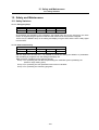
15. Safety and Maintenance..................................................................................................
15.1 Safety Switches .........................................................................................................
15.1.1 Emergency Stop................................................................................................
15.1.2 Data Protection Key ..........................................................................................
15.2 Display for Ensuring Safety .......................................................................................
15.2.1 NC Warning.......................................................................................................
15.2.2 NC Alarm...........................................................................................................
15.2.3 Operation Stop Cause ......................................................................................
15.2.4 Emergency Stop Cause ....................................................................................
15.2.5 Temperature Detection .....................................................................................
15.3 Protection ...................................................................................................................
15.3.1 Stroke End (Over Travel) ..................................................................................
15.3.2 Stored Stroke Limit............................................................................................
15.3.2.1 Stored Stroke Limit I/II.........................................................................
15.3.2.2 Stored Stroke Limit IB .........................................................................
15.3.2.3 Stored Stroke Limit IIB ........................................................................
15.3.2.4 Stored Stroke Limit IC .........................................................................
15.3.3 Stroke Check Before Movement.......................................................................
15.3.4 Chuck/Tail Stock Barrier Check; G22/G23 .......................................................
15.3.5 Interlock.............................................................................................................
15.3.6 External Deceleration........................................................................................
15.3.8 Door Interlock...................................................................................................
15.3.8.1 Door Interlock I ....................................................................................
15.3.8.2 Door Interlock II ...................................................................................
15.3.9 Parameter Lock................................................................................................
15.3.10 Program Protect (Edit Lock B, C) ...................................................................
15.3.11 Program Display Lock.....................................................................................
15.4 Maintenance and Troubleshooting ............................................................................
15.4.1 History Diagnosis ..............................................................................................
15.4.2 Setup/Monitor for Servo and Spindle................................................................
15.4.3 Data Sampling...................................................................................................
15.4.5 Machine Operation History Monitor ..................................................................
15.4.6 NC Data Backup ...............................................................................................
15.4.7 PLC I/F Diagnosis .............................................................................................
192
192
192
192
193
193
193
194
194
194
195
195
195
196
198
199
199
199
200
201
201
202
202
203
204
204
205
206
206
206
206
207
207
207
16. Cabinet and Installation ..................................................................................................
16.1 Cabinet Construction .................................................................................................
16.2 Power Supply, Environment and Installation Conditions ..........................................
208
208
211
17. Servo/Spindle System.....................................................................................................
17.1 Feed Axis ...................................................................................................................
17.1.1 MDS-C1-V1/C1-V2 (200V) ...............................................................................
17.1.4 MDS-B-SVJ2 (Compact and Small Capacity) ..................................................
17.1.6 MDS-R-V1/R-V2 (200V Compact and Small Capacity)................................
17.2 Spindle .......................................................................................................................
17.2.1 MDS-C1-SP/C1-SPM/B-SP (200V) ..................................................................
17.2.3 MDS-B-SPJ2 (Compact and Small Capacity) ..................................................
213
213
213
213
213
214
214
214
vi
17.3 Auxiliary Axis..............................................................................................................
17.3.1 Index/Positioning Servo: MR-J2-CT .................................................................
17.4 Power Supply.............................................................................................................
17.4.1 Power Supply: MDS-C1-CV/B-CVE .................................................................
17.4.2 AC Reactor for Power Supply...........................................................................
17.4.3 Ground Plate .....................................................................................................
17.4.4 Power Supply: MDS-A-CR (Resistance Regeneration) ...................................
214
214
215
215
215
215
215
18. Machine Support Functions ...........................................................................................
18.1 PLC ............................................................................................................................
18.1.1 PLC Basic Function ..........................................................................................
18.1.1.1 Built-in PLC Basic Function..................................................................
18.1.2 Built-in PLC Processing Mode ..........................................................................
18.1.2.2 MELSEC Development Tool I/F...........................................................
18.1.3 Built-in PLC Capacity (Number of Steps) .........................................................
18.1.4 Machine Contact Input/Output I/F.....................................................................
18.1.6 PLC Development.............................................................................................
18.1.6.2 MELSEC Development Tool ................................................................
18.1.7 C Language Function........................................................................................
18.1.12 GOT Connection .............................................................................................
18.1.12.1 CPU Direct Connection (RS-422/RS-232C)...................................
18.1.12.2 CC-Link Connection (Remote Device)...............................................
18.1.12.3 CC-Link Connection (Intelligent Terminal) .....................................
18.1.12.5 Ethernet Connection ......................................................................
18.1.13 PLC Message..................................................................................................
18.1.13.1 Japanese ............................................................................................
18.1.13.2 English................................................................................................
18.1.13.13 Polish................................................................................................
18.2 Machine Construction ................................................................................................
18.2.1 Servo OFF.........................................................................................................
18.2.2 Axis Detach .......................................................................................................
18.2.3 Synchronous Control ........................................................................................
18.2.3.1 Position Tandem ..................................................................................
18.2.3.2 Speed Tandem.................................................................................
18.2.3.3 Torque Tandem................................................................................
18.2.7 Auxiliary Axis Control (J2-CT)...........................................................................
18.3 PLC Operation ...........................................................................................................
18.3.1 Arbitrary Feed in Manual Mode ........................................................................
18.3.3 PLC Axis Control...............................................................................................
18.4 PLC Interface .............................................................................................................
18.4.1 CNC Control Signal...........................................................................................
18.4.2 CNC Status Signal ............................................................................................
18.4.5 DDB...................................................................................................................
18.5 Machine Contact I/O ..................................................................................................
18.6 External PLC Link ......................................................................................................
18.6.4 CC-Link .............................................................................................................
18.6.6 DeviceNet (Master/Slave) .................................................................................
18.6.7 MELSEC-Q Series Input/Output/Intelligent Function Unit Connection ............
18.6.9 MELSECNET/10 ...............................................................................................
18.6.10 Ethernet I/F (MELSEC Communication Protocol) ..........................................
18.7 Installing S/W for Machine Tools ...............................................................................
18.7.1 APLC .................................................................................................................
18.7.6 EzSocket I/F......................................................................................................
216
216
216
216
220
220
220
221
225
225
225
226
226
227
227
228
229
229
229
229
230
230
231
232
232
234
234
235
236
236
237
238
238
239
241
242
243
243
247
248
250
254
255
255
255
vii
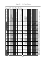
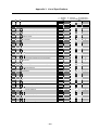
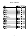
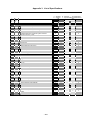
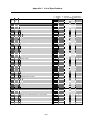
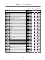
Appendix 1. List of Specifications.......................................................................................
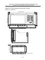
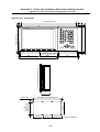
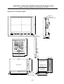
Appendix 2. Outline and Installation Dimension Drawings of Units ...............................
Appendix 2.1 Outline Drawing of Control Unit..................................................................
Appendix 2.2 Outline Drawing of Communication Terminal ............................................
Appendix 2.2.1 FCUA-CT100 .....................................................................................
Appendix 2.2.2 FCUA-CR10.......................................................................................
Appendix 2.2.3 FCUA-LD100 .....................................................................................
Appendix 2.2.4 FCUA-LD10, KB20 ............................................................................
Appendix 2.2.5 FCU6-DUT32, KB021 ........................................................................
Appendix 2.2.6 Communication Terminal...................................................................
Appendix 2.3 Outline Drawing of Remote I/O Unit ...........................................................
Appendix 3. List of Specifications.......................................................................................
viii
256
257
257
258
258
259
260
261
262
263
264
265
1. Control Axes
1.1 Control Axes
1. Control Axes
The NC axis, spindle, PLC axis are generically called the control axis.
The NC axis is an axis that can be manually operated, or automatically operated with the machining
program.
The PLC axis is an axis that can be controlled from the PLC ladder.
1.1 Control Axes
1.1.1 Number of Basic Control Axes (NC axes)
C6
T system
1
L system
2
M system
3
C64
L system
2
T system
1
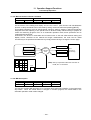
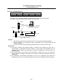
1.1.2 Max. Number of Control Axes (NC axes + Spindles + PLC axes + Auxiliary axes)
A number of axes that are within the maximum number of control axes, and that does not exceed
the maximum number given for the NC axis, spindle, PLC axis and auxiliary axis can be used.
For example, if 14 NC axes are used, this alone is the maximum number of control axes, so a
spindle, PLC axis and auxiliary axis cannot be connected.
The connection order is the NC axis, PLC axis, spindle and auxiliary axis.
Max. number of control axes (NC axes + spindles + PLC axes + auxiliary axes)
C6
T system
7
L system
7
M system
14
C64
L system
14
T system
14
Max. number of axes (NC axes + spindles + PLC axes)
C6
T system
4
L system
6
M system
14
C64
L system
14
T system
14
Max number of servo axes (NC axes + PLC axes)
C6
T system
2
L system
4
M system
14
C64
L system
14
T system
14
Max. number of NC axes (in total for all the part systems)
C6
T system
2
L system
4
M system
14
C64
L system
12
-1-
T system
14
1. Control Axes
1.1 Control Axes
Max. number of spindles
Includes analog spindles.
C6
T system
2 (1)
L system
2 (1)
C64
L system
4
M system
3
T system
7 (1)
Values in parentheses indicate the maximum number of spindles per part system.
Max. number of PLC axes
C6
T system
–
L system
–
M system
7
C64
L system
7
T system
7
C64
L system
∆7
T system
∆7
Max. number of auxiliary axes (MR-J2-CT)
C6
T system
∆5
L system
∆5
M system
∆7
1.1.3 Number of Simultaneous Contouring Control Axes
Simultaneous control of all axes is possible as a principle in the same part system.
However, for actual use, the machine tool builder specification will apply.
C6
T system
2
L system
2
C64
L system
4
T system
2
C64
L system
4
T system
2
M system
1
C64
L system
1
T system
1
M system
∆3
C64
L system
∆3
T system
∆7
M system
4
1.1.4 Max. Number of NC Axes in a Part System
C6
T system
2
L system
2
M system
6
1.2 Control Part System
1.2.1 Standard Number of Part Systems
C6
T system
1
L system
1
1.2.2 Max. Number of Part Systems
C6
T system
∆2
L system
∆2
For actual use, the machine tool builder specification will apply.
-2-
1.
Control Axes
1.3 Control Axes and Operation Modes
1.3 Control Axes and Operation Modes
1.3.2 Memory Mode
C6
T system
{
L system
{
M system
{
C64
L system
{
T system
{
The machining programs stored in the memory of the NC unit are run.
1.3.3 MDI Mode
C6
T system
{
L system
{
M system
{
C64
L system
{
T system
{
The MDI data stored in the memory of the NC unit is executed. Once executed, the MDI data is set
to the "setting incomplete" status, and the data will not be executed unless the "setting completed"
status is established by performing screen operations.
-3-
2.
Input Command
2.1 Data Increment
2. Input Command
2.1 Data Increment
Least command increment: 1 µm (Least input increment: 1 µm)
C6
T system
{
L system
{
M system
{
C64
L system
{
T system
{
Least command increment: 0.1 µm (Least input increment: 0.1 µm)
C6
T system
∆
L system
∆
M system
∆
C64
L system
∆
T system
∆
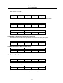
The data increment handled in the controller include the least input increment, least command
increment and least detection increment. Each type is set with parameters.
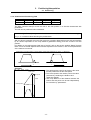
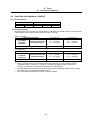
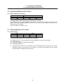
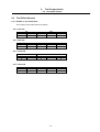
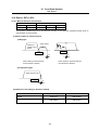
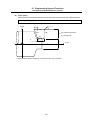
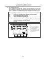
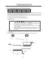
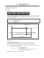
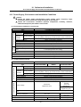
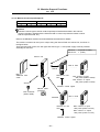
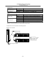
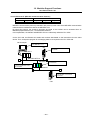
(1) The least input increment indicates the increment handled in the internal processing of the
controller. The counter and tool offset data, etc., input from the screen is handled with this
increment. This increment is applied per part system (all part systems, PLC axis).
Input
increment
(parameter)
B
Least input increment
C
Increment type
Metric unit system
Linear axis
Rotary axis
(Unit = mm)
(Unit = °)
0.001
0.001
0.0001
0.0001
Inch unit system
Linear axis
Rotary axis
(Unit = inch)
(Unit = °)
0.0001
0.001
0.00001
0.0001
(Note) The inch and metric systems cannot be used together.
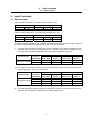
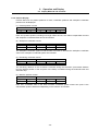
(2) The command increment indicates the command increment of the movement command in the
machining program. This can be set per axis.
Command
increment
(parameter)
10
100
Command increment
1000
10000
Increment type
Metric unit system
Linear axis
Rotary axis
(Unit = mm)
(Unit = °)
0.001
0.001
0.01
0.01
0.1
0.1
1.0
1.0
Inch unit system
Linear axis
Rotary axis
(Unit = inch)
(Unit = °)
0.0001
0.001
0.001
0.01
0.01
0.1
0.1
1.0
(Note) The inch and metric systems cannot be used together.
(3) The least detection increment indicates the detection increment of the NC axis and PLC axis
detectors. The increment is determined by the detector being used.
-4-
2.
Input Command
2.2 Unit System
2.2 Unit System
2.2.1 Inch/Metric Changeover; G20/G21
C6
T system
∆
L system
∆
M system
∆
C64
L system
∆
T system
∆
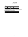
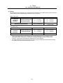
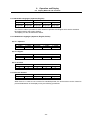
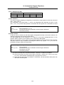
The unit systems of the data handled in the controller include the metric unit system and inch unit
system. The type can be designated with the parameters and machining program. The unit system
can be set independently for the (1) Program command, (2) Setting data such as offset amount and
(3) Parameters.
Unit system
Metric unit system
Inch unit system
Length data
1.0
1.0
Meaning
1.0 mm
1.0 inch
(Note) For the angle data, 1.0 means 1 degree (°) regardless of the unit system.
Data
Parameter
0
I_inch
1
M_inch
Screen data
(Offset amount, etc.)
Machining program
0
1
G20
G21
G20
G21
Inch unit system
Metric unit system
Inch unit system
Metric unit system
Parameter
Metric unit system
Not affected
Inch unit system
Not affected
Not affected
Metric unit system
Inch unit system
(Note 1) The parameter changeover is valid after the power is turned ON again.
(Note 2) Even if parameter "I_inch" is changed, the screen data (offset amount, etc.) will not be
automatically converted.
(Note 3) When the power is turned ON or resetting is performed, the status of the G20/G21 modal
depends on the "I_G20" parameter setting.
-5-
2.
Input Command
2.3 Program Format
2.3 Program Format
2.3.1 Character Code
C6
T system
{
L system
{
M system
{
C64
L system
{
T system
{
The command information used in this CNC system consists of alphanumerics and symbols which
are collectively known as characters.
These characters are expressed as combinations of 8-bit data inside the NC unit.
The expressions formed in this way are called codes, and this CNC system uses shift JIS codes.
The characters which are valid in this CNC system are listed below.
Character
0 to 9
A to Z
+
–
.
,
/
%
CR
LF/NL
(
)
:
#
∗
=
[
]
SP
!
$
BS
HT
&
'(Apostrophe)
;
<
>
?
@
"
DEL
NULL
Remarks
Always significant
Always significant
Always significant
Always significant
Always significant
Always significant
Always significant
Always significant
Always significant
Always significant
Always significant
Always significant
Always significant
Always significant
Always significant
Always significant
Always significant
Always significant
Always significant
Always significant
Always significant
An error results during operation (except when the character is part of a comment).
An error results during operation (except when the character is part of a comment).
An error results during operation (except when the character is part of a comment).
An error results during operation (except when the character is part of a comment).
An error results during operation (except when the character is part of a comment).
An error results during operation (except when the character is part of a comment).
An error results during operation (except when the character is part of a comment).
An error results during operation (except when the character is part of a comment).
An error results during operation (except when the character is part of a comment).
An error results during operation (except when the character is part of a comment).
Always ignored
Always ignored
-6-
2.
Input Command
2.3 Program Format
2.3.2 Program Format
2.3.2.1 Format 1 for Lathe (G code list 2, 3)
C6
T system
–
L system
{
M system
–
C64
L system
{
T system
–
The G-code of L system is selected by parameter.
This specification manual explains the G function with G-code series 3 as standard.
2.3.2.4 Format 1 for Machining Center (G code list 1)
C6
T system
{
L system
–
M system
{
C64
L system
–
-7-
T system
{
2.
Input Command
2.4 Command Value
2.4 Command Value
2.4.1 Decimal Point Input I, II
C6
T system
{
L system
{
M system
{
C64
L system
{
T system
{
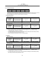
There are two types of the decimal point input commands and they can be selected by parameter.
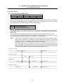
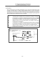
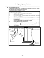
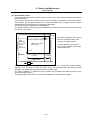
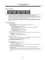
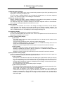
(1) Decimal point input type I (When parameter #1078 Decpt2 is 0.)
When axis coordinates and other data are supplied in machining program commands, the
assignment of the program data can be simplified by using the decimal point input. The minimum
digit of a command not using a decimal point is the same as the least command increment.
Usable addresses can be applied not only to axis coordinate values but also to speed commands
and dwell commands.
The decimal point position serves as the millimeter unit in the metric mode, as the inch unit in the
inch mode and as the second unit in a time designation of dwell command.
(2) Decimal point input type II (When parameter #1078 Decpt2 is 1.)
As opposed to type I, when there is no decimal point, the final digit serves as the millimeter unit in
the metric mode, as the inch unit in the inch mode and as the second unit in the time designation.
The "." (point) must be added when commands below the decimal point are required.
Unit interpretation (for metric system)
Type I
Type II
G00 X100. Y-200.5
X100mm, Y-200.5mm
←
G1 X100 F20.
X100µm, F20mm/min
X100mm, F20mm/min
G1 Y200 F100 (*1)
Y200µm, F100mm/min
Y200mm, F100mm/min
G4 X1.5
Dwell 1.5 s
←
G4 X2
2ms
2s
(*1) The F unit is mm/min for either type (inch system : inch/min).
-8-
2.
Input Command
2.4 Command Value
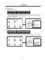
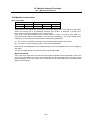
2.4.2 Absolute/Incremental Command; G90/G91
C6
T system
{
L system
{
M system
{
C64
L system
{
T system
{
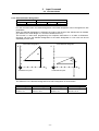
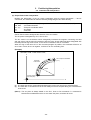
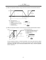
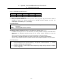
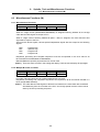
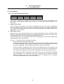
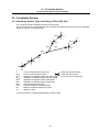
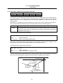
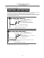
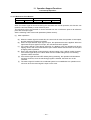
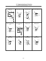
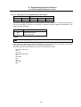
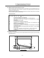
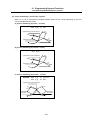
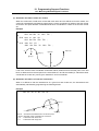
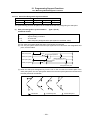
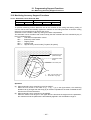
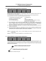
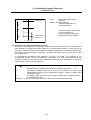
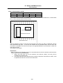
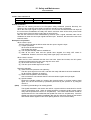
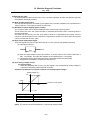
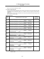
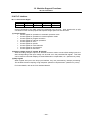
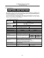
(1) T system, M system
When axis coordinate data is issued in a machining program command, either the incremental
command method (G91) that commands a relative distance from the current position or the
absolute command method (G90) that moves to a designated position in a predetermined
coordinate system can be selected.
The absolute and incremental commands can be both used in one block, and are switched with
G90 or G91. However, the arc radius designation (R) and arc center designation (I, J, K) always
use incremental designations.
G90 ... Absolute command (absolute value command)
G91 ... Incremental command (incremental value command)
These G codes can be commanded multiple times in one block.
Example
G90 X100.
Absolute value
G91 Y200.
Incremental value
;
G90 Z300.
Absolute value
(Note 1) As with the memory command, if there is no G90/G91 designation in the MDI command,
the previously executed modal will be followed.
(Incremental value command)
(Absolute value command)
G 90 X 100. Y100. ;
G 91 X 100. Y100. ;
End
point
End point
Y100.
Y100.
Y100.
Current position X 100.
Current position
Program coordinate
(0, 0)
(0, 0)
X 100.
-9-
X100.
2.
Input Command
2.4 Command Value
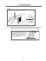
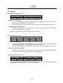
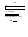
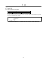
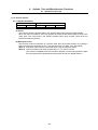
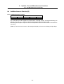
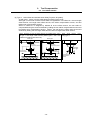
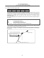
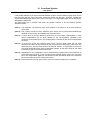
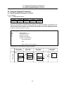
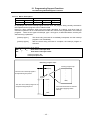
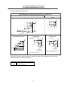
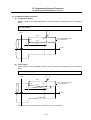
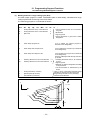
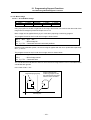
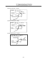
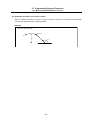
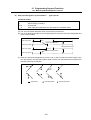
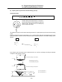
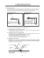
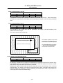
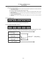
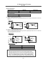
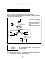
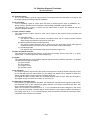
(2) L system
When axis coordinate data is issued in a machining program command, either the incremental
command method that commands a relative distance from the current position or the absolute
command method that moves to a designated position in a predetermined coordinate system can
be selected.
When issuing an incremental value command, the axis address to be commanded as the
incremental axis name is registered in the parameter. However, the arc radius designation (R) and
arc center designation (I, J, K) always use incremental designations.
Absolute command (absolute value command) ... X, Z
Incremental command (incremental value command) ... U, W
Example
G00
X100.
W200.
Absolute value
Incremental value
(Absolute value command)
(Incremental value command)
G 00 U – u1 W – w1 ;
;
G 00 X x1 Z z1 ;
Current position
X
Current position
X
End point
u1
2
x1
Z
End point
w1
z1
Z
(0,0)
The above drawing shows the case
for the diameter command.
(Note)
The above drawing shows the case
for the diameter command.
In addition to the above command method using the above axis addresses, the absolute
value command and incremental value command can be switched by commanding the G
code (G90/G91). (Select with the parameters.)
- 10 -
2.
Input Command
2.4 Command Value
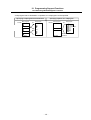
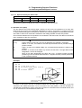
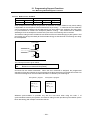
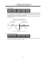
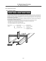
2.4.3 Diameter/Radius Designation
C6
T system
–
L system
{
C64
L system
{
M system
–
T system
–
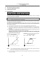
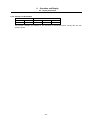
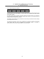
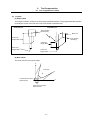
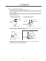
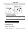
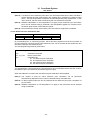
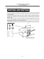
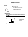
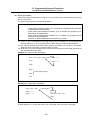
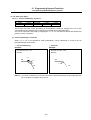
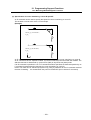
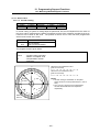
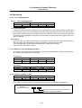
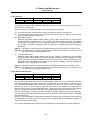
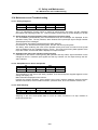
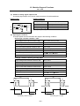
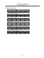
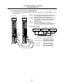
For axis command value, the radius designation or diameter designation can be changed over with
parameters.
When the diameter designation is selected, the scale of the length of the selected axis is doubled.
(For instance, an actual length of 1 mm will be treated as 2 mm.)
This function is used when programming the workpiece dimensions on a lathe as diameters.
Changing over from the diameter designation to the radius designation or vice versa can be set
separately for each axis.
X-axis radius designation
X-axis diameter designation
X
X
u4
x6
u4
x6
Z
Coordinate zero point
Z
Coordinate zero point
The difference in the diameter designation and radius designation is shown below.
Absolute value command
Incremental value command
Radius designation Diameter designation Radius designation Diameter designation
Actual movement
Actual movement
Actual movement
Actual movement
amount = x1
amount = 2 x1
amount = u1
amount = 2 u1
- 11 -
2.
Input Command
2.5 Command Value and Setting Value Range
2.5 Command Value and Setting Value Range
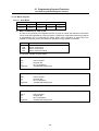
2.5.1 Command Value and Setting Value Range
C6
T system
{
L system
{
M system
{
C64
L system
{
T system
{
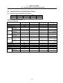
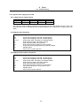
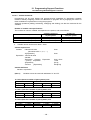
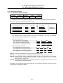
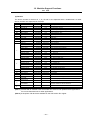
<Brief summary of format details>
[T system, M system]
Program number
Sequence number
Preparatory function
0.001(°) mm/
Movement
0.0001 inch
axis
0.0001(°) mm/
0.00001 inch
0.001(°) mm/
Arc and
0.0001 inch
cutter
0.0001(°) mm/
radius
0.00001 inch
0.001(°) mm/
0.0001 inch
Dwell
0.0001(°) mm/
0.00001 inch
Feed
function
0.001(°) mm/
0.0001 inch
0.0001 (°) mm/
0.00001 inch
Tool offset
Miscellaneous function (M)
Spindle function (S)
Tool function (T)
2nd miscellaneous function
Subprogram
0.001(°) mm/
Fixed
0.0001 inch
cycle
0.0001(°) mm/
0.00001 inch
←
←
←
Rotary axis
(Metric command)
←
←
←
Rotary axis
(Inch command)
←
←
←
X+53 Y+53 Z+53 α+53
X+44 Y+44 Z+44 α+44
X+53 Y+53 Z+53 α+53
X+53 Y+53 Z+53 α+53
X+44 Y+44 Z+44 α+44
X+35 Y+35 Z+35 α+35
X+44 Y+44 Z+44 α+44
X+44 Y+44 Z+44 α+44
I+53 J+53 K+53 R+53
I+44 J+44 K+44 R+44
I+53 J+53 K+53 R+53
I+44 J+44 K+44 R+44
I+35 J+35 K+35 R+35
I+44 J+44 K+44 R+44
X+53/P+8
←
←
←
X+44/P+8
←
←
←
Metric command
Inch command
08
N5
G3/G21
I+44 J+44 K+44 R+44
(Note 5)
I+35 J+35 K+35 R+35
(Note 5)
F44(Feed per minute)
F63(Feed per minute)
F44(Feed per minute)
F63(Feed per minute)
F34(Feed per revolution)
F43(Feed per revolution) F34(Feed per revolution) F43(Feed per revolution)
(Note 6)
F35(Feed per minute)
F54(Feed per minute)
F35(Feed per minute)
F54(Feed per minute)
F25(Feed per revolution)
F34(Feed per revolution) F25(Feed per revolution) F34(Feed per revolution)
(Note 6)
H3 D3
←
←
←
M8
←
←
←
S8
←
←
←
T8
←
←
←
A8/B8/C8
←
←
←
P8 H5 L4
←
←
←
R+53 Q53 P8 L4
←
←
←
R+44 Q44 P8 L4
←
←
←
- 12 -
2.
Input Command
2.5 Command Value and Setting Value Range
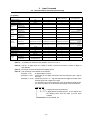
[L system]
Program number
Sequence number
Preparatory function
0.001(°) mm/
Movement
0.0001 inch
axis
0.0001(°) mm/
0.00001 inch
0.001(°) mm/
Arc and
0.0001 inch
cutter
0.0001(°) mm/
radius
0.00001 inch
0.001(°) mm/
0.0001 inch
Dwell
0.0001(°) mm/
0.00001 inch
Feed
function
0.001(°) mm/
0.0001 inch
0.0001(°) mm/
0.00001 inch
Tool offset
Miscellaneous function (M)
Spindle function (S)
Tool function (T)
2nd miscellaneous function
Subprogram
0.001(°) mm/
Fixed
0.0001 inch
cycle
0.0001(°) mm/
0.00001 inch
←
←
←
Rotary axis
(Metric command)
←
←
←
Rotary axis
(Inch command)
←
←
←
X+53 Z+53 α+53
X+44 Z+44 α+44
X+53 Z+53 α+53
X+53 Z+53 α+53
X+44 Z+44 α+44
X+35 Z+35 α+35
X+44 Z+44 α+44
X+44 Z+44 α+44
I+53 K+53 R+53
I+44 K+44 R+44
I+53 K+53 R+53
I+44K+44 R+44
I+35 K+35 R+35
X+53/P+8
←
←
←
X+44/P+8
←
←
←
Metric command
Inch command
08
N5
G3/G21
I+44 K+44 R+44
I+44 K+44 R+44
(Note 5)
I+35 K+35 R+35
(Note 5)
F44(Feed per minute)
F63(Feed per minute)
F44(Feed per minute)
F63(Feed per minute)
F34(Feed per revolution)
F43(Feed per revolution) F34(Feed per revolution) F43(Feed per revolution)
(Note 6)
F35(Feed per minute)
F54(Feed per minute)
F35(Feed per minute)
F54(Feed per minute)
F25(Feed per revolution)
F34(Feed per revolution) F25(Feed per revolution) F34(Feed per revolution)
(Note 6)
T1/T2
←
←
←
M8
←
←
←
S8
←
←
←
T8
←
←
←
A8/B8/C8
←
←
←
P8 H5 L4
←
←
←
R+53 Q53 P8 L4
←
←
←
R+44 Q44 P8 L4
←
←
←
(Note 1) α indicates the additional axis address, such as A, B or C.
(Note 2) The No. of digits check for a word is carried out with the maximum number of digits of
that address.
(Note 3) Numerals can be used without the leading zeros.
(Note 4) The meanings of the details are as follows :
Example 1 : 08
: 8-digit program number
Example 2 : G21 : Dimension G is 2 digits to the left of the decimal point, and 1 digit to
the right.
Example 3 : X+53 : Dimension X uses + or - sign and represents 5 digits to the left of the
decimal point and 3 digits to the right.
For example, the case for when the X axis is positioned (G00) to the
45.123 mm position in the absolute value (G90) mode is as follows :
G00 X45.123 ;
3 digits below the decimal point
5 digits above the decimal point, so it's +00045, but
the leading zeros and the mark (+) have been
omitted.
G0 is possible, too.
- 13 -
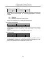
2.
Input Command
2.5 Command Value and Setting Value Range
(Note 5) If an arc is commanded using a rotary axis and linear axis while inch commands are
being used, the degrees will be converted into 0.1 inches for interpolation.
(Note 6) While inch commands are being used, the rotary axis speed will be in increments of 10
degrees.
Example : With the F1. (per-minute-feed) command, this will become the 10
degrees/minute command.
(Note 7) The decimal places below the decimal point are ignored when a command, such as an S
command, with an invalid decimal point has been assigned with a decimal point.
(Note 8) This format is the same for the value input from the memory, MDI or setting and display
unit.
(Note 9) Command the program No. in an independent block. Command the program No. in the
head block of the program.
- 14 -
2.
Input Command
2.5 Command Value and Setting Value Range
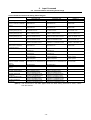
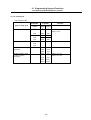
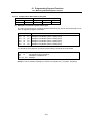
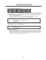
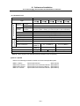
<List of Command Value and Setting Value Ranges>
Linear axis
Input unit: mm
Least setting increment
Maximum stroke
(Value on machine coordinate
system)
Maximum command value
Rapid traverse rate
(Including during dry run)
M system cutting feed rate
(Including during dry run)
L system cutting feed rate
(Including during dry run)
M system synchronous feed
L system synchronous feed
2nd to 4th reference point
offset (value on machine
coordinate system)
Tool offset amount (shape)
Tool offset amount (wear)
Incremental feed amount
Handle feed amount
Soft limit range
(value on machine coordinate
system)
Dwell time
Backlash compensation
amount
Pitch error compensation
M system thread lead (F)
M system thread lead
(Precise E)
L system thread lead (F)
L system thread lead
(Precise E)
Rotary axis
Input unit: inch
Degree (°)
0.001/0.0001
±99999.999 mm
±9999.9999 mm
0.0001/0.00001
±9999.9999 inch
±999.99999 inch
0.001/0.0001
±99999.999 °
±9999.9999 °
±99999.999 mm
±9999.9999 mm
1 to 1000000 mm/min
1 to 100000 mm/min
0.01 to 1000000 mm/min
0.001 to 100000 mm/min
0.001 to 1000000 mm/min
0.0001 to 100000 mm/min
0.001 to 999.999 mm/rev
0.0001 to 99.9999 mm/rev
0.0001 to 999.9999 mm/rev
0.00001 to 99.99999 mm/rev
±99999.999 mm
±9999.9999 mm
±9999.9999 inch
±999.99999 inch
1 to 39370 inch/min
1 to 3937 inch/min
0.001 to 100000 inch/min
0.0001 to 10000 inch/min
0.0001 to 39370.0787 inch/min
0.00001 to 3937.00787 inch/min
0.0001 to 999.9999 inch/rev
0.00001 to 99.99999 inch/rev
0.000001 to 99.999999 inch/rev
0.0000001 to 9.9999999 inch/rev
±9999.9999 inch
±999.99999 inch
±99999.999 °
±9999.9999 °
1 to 1000000 °/min
1 to 100000 °/min
0.01 to 1000000 °/min
0.001 to 100000 °/min
0.001 to 1000000 °/min
0.0001 to 100000 °/min
0.01 to 999.99 °/rev
0.001 to 99.999 °/rev
0.0001 to 999.9999 °/rev
0.00001 to 99.99999 °/rev
±99999.999 °
±9999.9999 °
±999.999 mm
±99.9999 mm
±9999.999 mm
±999.9999 mm
0.001 mm/pulse
0.0001 mm/pulse
0.001 mm/pulse
0.0001 mm/pulse
–99999.999 mm to +99999.999 mm
–9999.9999 mm to +9999.9999 mm
±99.9999 inch
±9.99999 inch
±9.9999 inch
±0.99999 inch
0.0001 inch/pulse
0.00001 inch/pulse
0.0001 inch/pulse
0.00001 inch/pulse
–9999.9999 inch to +9999.9999 inch
–999.99999 inch to +999.99999 inch
0.001 °/pulse
0.0001 °/pulse
0.001 °/pulse
0.0001 °/pulse
1 to 359.999 °
1 to 359.9999 °
0 to 99999.999 s
0 to ±9999 pulse
0 to 99999.999 s
0 to ±9999 pulse
0 to ±9999 pulse
0 to ±9999 pulse
0.001 to 999.999 mm/rev
0.0001 to 99.9999 mm/rev
0.00001 to 999.99999 mm/rev
0.000001 to 99.999999 mm/rev
0.0001 to 999.9999 mm/rev
0.00001 to 99.99999 mm/rev
0.00001 to 999.99999 mm/rev
0.000001 to 99.999999 mm/rev
0 to ±9999 pulse
0.0001 to 99.9999 inch/rev
0.00001 to 9.99999 inch/rev
0.000001 to 39.370078 inch/rev
0.000001 to 3.937007 inch/rev
0.000001 to 99.999999 inch/rev
0.0000001 to 9.9999999 inch/rev
0.000010 to 9.9999999 inch/rev
0.0000010 to 0.99999999 inch/rev
0 to ±9999 pulse
(Note 1) The second line in the table applies when the least setting increment is 0.001, 0.0001
from the first line.
- 15 -
3.
Positioning/Interpolation
3.1 Positioning
3.
Positioning/Interpolation
3.1 Positioning; G0, G60
3.1.1 Positioning; G0
C6
T system
{
L system
{
M system
{
C64
L system
{
T system
{
This function carries out positioning at high speed using rapid traverse with the movement
command value given in the program.
G00 Xx1 Yy1 Zz1 ; (Also possible for additional axes A, B, C, U, V, W simultaneously)
x1, y1, z1: numerical values denoting the position data
The above command positions the tool by rapid traverse. The tool path takes the shortest distance
to the end point in the form of a straight line.
For details on the rapid traverse feed rate of the NC, refer to the section entitled "Rapid Traverse
Rate". Since the actual rapid traverse feed rate depends on the machine, refer to the specifications
of the machine concerned.
(1) The rapid traverse feed rate for each axis can be set independently with parameters.
(2) The number of axes which can be driven simultaneously depends on the specifications
(number of simultaneously controlled axes). The axes can be used in any combination within
this range.
(3) The feed rate is controlled within the range that it does not exceed the rapid traverse rate of
each axis and so that the shortest time is taken. (Linear type)
Parameter setting enables movement at the rapid traverse rates of the respective axes
independently for each axis. In this case, the tool path does not take the form of a straight line
to the end point. (Non-Linear type)
(Example) Linear type (Moves lineary
to the end point.)
(Example) Non-linear type (Each axis moves at
G 00 G 91
G 00 G 91 X 100. Y 100. ;
X 100.
each parameter speed.)
Y 100. ;
Y
End point
Y
End point
100.
100.
Current position
Current position 100.
100.
X
X
(Note)
If the acceleration/deceleration conditions differ between the axes, the path will not be
linear to the end point even when using the linear type.
(4) The tool is always accelerated at the start of the program command block and decelerated at
the end of the block.
- 16 -
3.
Positioning/Interpolation
3.1 Positioning
3.1.2 Unidirectional Positioning; G60
C6
T system
∆
L system
–
M system
∆
C64
L system
–
T system
∆
The G60 command always moves the tool to the final position in a direction determined with
parameters.
The tool can be positioned without backlash.
G60 Xx1 Yy1 Zz1 ; (Also possible for additional axes A, B, C, U, V, W simultaneously)
x1, y1, z1: numerical values denoting the position data
With the above command, the tool is first moved to a position distanced from the end point position
by an amount equivalent to the creep distance (parameter setting) and then moved to its final
position.
For details on the rapid traverse feed rate of the NC, refer to the section entitled "Rapid Traverse
Rate". Since the actual rapid traverse feed rate depends on the machine, refer to the specifications
of the machine concerned.
Positioning to the final point is shown below (when this positioning is in the "+" direction.)
+
–
(Example)
G60 G91 X100. Y100. ;
Interim point
End point
Y100.
Current position
1. The rapid traverse rate for each axis is the value
set with parameters as the G00 speed.
2. The vector speed to the interim point is the value
produced by combining the distance and
respective speeds.
3. The creep distance of the distance between the
interim and end points can be set independently
for each axis by "parameters".
X100.
- 17 -
3.
Positioning/Interpolation
3.2 Linear/Circular Interpolation
(Note 1) The processing of the above pattern will be followed even for the machine lock and Zaxis command cancel.
(Note 2) On the creep distance, the tool is moved with rapid traverse.
(Note 3) G60 is valid even for positioning in drilling in the fixed cycle.
(Note 4) When the mirror image function is on, the tool will be moved in the reverse direction by
mirror image as far as the interim position, but operation over the creep distance with the
final advance will not be affected by the mirror image.
3.2 Linear/Circular Interpolation; G1, G2/G3
3.2.1 Linear Interpolation; G1
C6
T system
{
L system
{
M system
{
C64
L system
{
T system
{
Linear interpolation is a function that moves a tool linearly by the movement command value
supplied in the program at the cutting feed rate designated by the F code.
G01 Xx1 Yy1 Zz1 Ff1 ; (Also possible for additional axes A, B, C, U, V, W
simultaneously)
x1, y1, z1 : numerical values denoting the position data
f1 : numerical value denoting the feed rate data
Linear interpolation is executed by the above command at the f1 feed rate. The tool path takes the
shortest distance to the end point in the form of a straight line.
For details on the f1 command values for NC, refer to the section entitled "Cutting Feed Rate".
Since the actual cutting feed rate depends on the machine, refer to the specifications of the
machine concerned.
(Example)
G01
G91
X100.
Y100.
F120 ;
Y
End point
Feed rate
(120mm/min)
Current
position
100.
100.
(85mm/min)
1. The cutting feed rate command
moves the tool in the vector direction.
2. The component speeds of each axis
are determined by the proportion of
respective command values to the
actual movement distance with linear
interpolation.
(85mm/min)
X
(1) The number of axes which can be driven simultaneously depends on the specifications
(number of simultaneously controlled axes). The axes can be used in any combination within
this range.
(2) The feed rate is controlled so that it does not exceed the cutting feed rate clamp of each axis.
(3) When a rotary axis has been commanded in the same block, it is treated as a linear axis in
degree(°) units (1° = 1mm), and linear interpolation is performed.
- 18 -
3.
Positioning/Interpolation
3.2 Linear/Circular Interpolation
3.2.2 Circular Interpolation (Center/Radius Designation); G2/G3
C6
T system
{
L system
{
M system
{
C64
L system
{
T system
{
(1) Circular interpolation with I, J, K commands
This function moves a tool along a circular arc on the plane selected by the plane selection G code
with movement command value supplied in the program.
G02(G03) Xx1 Yy1
G02, G03
Xx1, Yy1
Ii1, Jj1
Ff1
Ii1 Jj1 Ff1 ; (Also possible for additional axes A, B, C, U, V, W)
: Arc rotation direction
: End point coordinate values
: Arc center coordinate values
: Feed rate
The above commands move the tool along the circular arc at the f1 feed rate. The tool moves along
a circular path, whose center is the position from the start point designated by distance "i1" in the Xaxis direction and distance "j1" in the Y-axis direction, toward the end point.
The direction of the arc rotation is specified by
G02 or G03.
G02: Clockwise (CW)
G03: Counterclockwise (CCW)
The plane is selected by G17, G18 or G19.
G17: XY plane
G18: ZX plane
G19: YZ plane
Y
G17
X
G18
G02
G02
G03
(Example) See below for examples of circular
commands.
G03
X
Z
Y
Z
G19
Start point
G02
F
G03
I, J
Y
End point
Center
X
(a) The axes that can be commanded simultaneously are the two axes for the selected plane.
(b) The feed rate is controlled so that the tool always moves at a speed along the circumference
of the circle.
(c) Circular interpolation can be commanded within a range extending from 0° to 360°.
(d) The max. value of the radius can be set up to six digits above the decimal point.
(Note 1) The arc plane is always based on the G17, G18 or G19 command. If a command is
issued with two addresses which do not match the plane, an alarm will occur.
(Note 2) The axes configuring a plane can be designated by parameters. Refer to the section
entitled "Plane Selection".
- 19 -
3.
Positioning/Interpolation
3.2 Linear/Circular Interpolation
(2) R-specified circular interpolation
Besides the designation of the arc center coordinates using the above-mentioned I, J and K
commands, arc commands can also be issued by designating the arc radius directly.
G02(G03) Xx1 Yy1
G02, G03
Xx1, Yy1
Rr1
Ff1
Rr1 Ff1 ; (Also possible for additional axes A, B, C, U, V, W )
: Arc rotation direction
: End point coordinate values
: Arc radius
: Feed rate
G02 or G03 is used to designate the direction of the arc rotation.
The arc plane is designated by G17, G18 or G19.
The arc center is on the bisector which orthogonally intersects the segment connecting the start
and end points, and the point of intersection with the circle, whose radius has been designated with
the start point serving as the center, is the center coordinate of the arc command.
When the sign of the value of R in the command program is positive, the command will be for an
arc of 180° or less; when it is negative, it will be for an arc exceeding 180°.
(Example)
G02 G91 X100. Y100. R100. F120 ;
Y
Arc end point coordinates
(X, Y)
Feed rate:
120mm/min
R100.
Current position
(arc start point)
X
(a) The axes that can be commanded simultaneously are the two axes for the selected plane.
(b) The feed rate is controlled so that the tool always moves at a speed along the circumference
of the circle.
(Note 1) The arc plane is always based on the G17, G18 or G19 command. If a command is
issued with two addresses which do not match the plane, an alarm will occur.
- 20 -
3.
Positioning/Interpolation
3.2 Linear/Circular Interpolation
3.2.3 Helical Interpolation
C6
T system
–
L system
–
M system
∆
C64
L system
–
T system
–
With this function, any two of three axes intersecting orthogonally are made to perform circular
interpolation while the third axis performs linear interpolation in synchronization with the arc rotation.
This simultaneous 3-axis control can be exercised to machine large-diameter screws or 3dimensional cams.
G17
G02(G03)
G17
G02, G03
Xx1, Yy1
Zz1
Ii1, Jj1
Pp1
Ff1
Xx1
Yy1
Zz1
Ii1
Jj1
Pp1
Ff1
;
: Arc plane
: Arc rotation direction
: End point coordinate values for arc
: End point coordinate value of linear axis
: Arc center coordinate values
: Pitch No.
: Feed rate
(1) The arc plane is designated by G17, G18 or G19.
(2) G02 or G03 is used to designate the direction of the arc rotation.
(3) Absolute or incremental values can be assigned for the arc end point coordinates and the end
point coordinate of the linear axis, but incremental values must be assigned for the arc center
coordinates.
(4) The linear interpolation axis is the other axis which is not included in the plane selection.
(5) Command the speed in the component direction that represents all the axes combined for the
feed rate.
Pitch l1 is obtained by the formula below.
l1 = z1/((2π • p1 + θ)/2π)
θ = θe – θs = arctan (ye/xe) – arctan (ys/xs)
Where xs, ys are the start point coordinates (0 ≤ θ < 2π)
xe, ye are the end point coordinates
The combination of the axes which can be commanded simultaneously depends on the
specifications. The axes can be used in any combination under the specifications. The feed rate is
controlled so that the tool always moves at a speed along the circumference of the circle.
- 21 -
3.
Positioning/Interpolation
3.2 Linear/Circular Interpolation
(Example)
G91
G17
G02
X0.
Y200.
Z100. I–100.
J100.
Z
Command program path
Y
End
point
End point
X
W
J100 I-100
Y
Start point
Start point
X
XY plane projection path in command program
(Note 1) Helical shapes are machined by assigning linear commands for one axis which is not a
circular interpolation axis using an orthogonal coordinate system. It is also possible to
assign these commands to two or more axes which are not circular interpolation axes.
Z
When a simultaneous 4-axis command is used with
the V axis as the axis parallel to the Y axis, helical
interpolation will result for a cylinder which is
inclined as shown in the figure on the right. In other
words, linear interpolation of the Z and V axes is
carried out in synchronization with the circular
interpolation on the XY plane.
X
- 22 -
V
•End
point
•Start point
Y
4.
Feed
4.1 Feed Rate
4.
Feed
4.1 Feed Rate
4.1.1 Rapid Traverse Rate (m/min)
C6
T system
1000
L system
1000
M system
1000
C64
L system
1000
T system
1000
[T system, M system]
The rapid traverse rate can be set independently for each axis.
The rapid traverse rate is effective for G00, G27, G28, G29, G30 and G60 commands.
Override can be applied to the rapid traverse rate using the external signal supplied.
•
Rapid Traverse Rate setting range
Least input increment
B
C
Metric input
1~1000000 (mm/min, °/min)
1~100000 (mm/min, °/min)
Inch input
1~39370 (inch/min)
1~3937 (inch/min)
Least input increment B : 0.001 mm (0.0001 inch)
Least input increment C : 0.0001 mm (0.00001 inch)
[L system]
The rapid traverse rate can be set independently for each axis.
The rapid traverse rate is effective for G00, G27, G28, G29, G30 and G53 commands.
Override can be applied to the rapid traverse rate using the external signal supplied.
•
Rapid Traverse Rate setting range
Least input increment
B
Metric input
1~1000000 (mm/min, °/min)
Inch input
1~39370 (inch/min)
Least input increment B : 0.001 mm (0.0001 inch)
Least input increment C : 0.0001 mm (0.00001 inch)
- 23 -
C
1~100000 (mm/min, °/min)
1~3937 (inch/min)
4.
Feed
4.1 Feed Rate
4.1.2 Cutting Feed Rate (m/min)
C6
T system
1000
L system
1000
M system
1000
C64
L system
1000
T system
1000
[T system, M system]
This function specifies the feed rate of the cutting commands, and a feed amount per spindle
rotation or feed amount per minute is commanded.
Once commanded, it is stored in the memory as a modal value. The feed rate modal value is
cleared to zero only when the power is turned ON.
The maximum cutting feed rate is clamped by the cutting feed rate clamp parameter (whose setting
range is the same as that for the cutting feed rate).
• Cutting Feed Rate setting range
Least input increment
B
Metric input
1~1000000 (mm/min, °/min)
Inch input
1~39370 (inch/min)
C
1~100000 (mm/min, °/min)
1~3937 (inch/min)
Least input increment B : 0.001 mm (0.0001 inch)
Least input increment C : 0.0001 mm (0.00001 inch)
•
The cutting feed rate is effective for G01, G02, G03, G33 commands, etc. As to others, refer to
the interpolation specifications.
[L system]
This function specifies the feed rate of the cutting commands, and a feed amount per spindle
rotation or feed amount per minute is commanded.
Once commanded, it is stored in the memory as a modal value. The feed rate modal is cleared to
zero only when the power is turned ON.
The maximum cutting feed rate is clamped by the cutting feed rate clamp parameter (whose setting
range is the same as that for the cutting feed rate).
•
Cutting Feed Rate setting range
Least input increment
B
Metric input
1~1000000 (mm/min, °/min)
Inch input
1~39370 (inch/min)
C
1~100000 (mm/min, °/min)
1~3937 (inch/min)
Least input increment B : 0.001 mm (0.0001 inch)
Least input increment C : 0.0001 mm (0.00001 inch)
•
The cutting feed rate is effective for G01, G02, G03, G33 commands, etc. As to others, refer to
interpolation specifications.
- 24 -
4.
Feed
4.1 Feed Rate
4.1.3 Manual Feed Rate (m/min)
C6
T system
1000
L system
1000
M system
1000
C64
L system
1000
T system
1000
The manual feed rates are designated as the feed rate in the jog mode or incremental feed mode
for manual operation and the feed rate during dry run ON for automatic operation. The manual feed
rates are set with external signals.
The manual feed rate signals from the PLC includes two methods, the code method and numerical
value method.
Which method to be applied is determined with a signal common to the entire system.
The signals used by these methods are common to all axes.
• Setting range under the code method
Metric input
0.00 to 14000.00 mm/min (31 steps)
Inch input
0.000 to 551.000 inch/min (31 steps)
•
Setting range under the value setting method
Metric input
0 to 1000000.00 mm/min in 0.01 mm/min increments
Inch input
0 to 39370 inch/min in 0.001 inch/min increments
Multiplication factor PCF1 and PCF2 are available with the value setting method.
- 25 -
4.
Feed
4.2 Feed Rate Input Methods
4.2 Feed Rate Input Methods; G94/G95
4.2.1 Feed per Minute
C6
T system
{
L system
{
M system
{
C64
L system
{
T system
{
[T system, M system]
By issuing the G94 command, the commands from that block are issued directly by the numerical
value following F as the feed rate per minute (mm/min, inch/min).
Metric input (mm)
Least input increment
F command
increment
(mm/min)
without decimal point
with decimal point
Command range (mm/min)
Inch input (inch)
Least input increment
F command
increment
(inch/min)
without decimal point
with decimal point
Command range (inch/min)
•
•
•
(B) 0.001 mm
(C) 0.0001 mm
F1 = 1 mm/min
F1. = 1 mm/min
F1 = 1 mm/min
F1. = 1 mm/min
0.01~1000000.000
0.001~100000.000
(B) 0.0001 inch
(C) 0.00001 inch
F1 = 1 inch/min
F1. = 1 inch/min
F1 = 1 inch/min
F1. = 1 inch/min
0.001~100000.0000
0.001~10000.0000
When commands without a decimal point have been assigned, it is not possible to assign
commands under 1 mm/min (or 1 inch/min). To assign commands under 1 mm/min (or 1
inch/min), ensure that commands are assigned with a decimal point.
The initial status after power-ON can be set to asynchronous feed (per-minute-feed) by setting
the "Initial synchronous feed" parameter to OFF.
The F command increments are common to all part systems.
- 26 -
4.
Feed
4.2 Feed Rate Input Methods
[L system]
By issuing the G94 command, the commands from that block are issued directly by the numerical
value following F as the feed rate per minute (mm/min, inch/min).
Metric input (mm)
Least input increment
F command
increment
(mm/min)
without decimal point
with decimal point
Command range (mm/min)
Inch input (inch)
Least input increment
F command
increment
(inch/min)
without decimal point
with decimal point
Command range (inch/min)
•
•
(B) 0.001 mm
(C) 0.0001 mm
F1 = 1 mm/min
F1. = 1 mm/min
F1 = 1 mm/min
F1. = 1 mm/min
0.001~1000000.000
0.0001
~100000.0000
(B) 0.0001 inch
(C) 0.00001 inch
F1 = 1 inch/min
F1. = 1 inch/min
F1 = 1 inch/min
F1. = 1 inch/min
0.0001~39370.0787
0.00001~3937.00787
When commands without a decimal point have been assigned, it is not possible to assign
commands under 1 mm/min (or 1 inch/min). To assign commands under 1 mm/min (or 1
inch/min), ensure that commands are assigned with a decimal point.
The initial status after power-ON can be set to asynchronous feed (per-minute-feed) by setting
the "Initial synchronous feed" parameter to OFF.
- 27 -
4.
Feed
4.2 Feed Rate Input Methods
4.2.2 Feed per Revolution
C6
T system
∆
L system
∆
M system
∆
C64
L system
∆
T system
∆
By issuing the G95 command, the commands from that block are issued directly by the numerical
value following F as the feed rate per spindle revolution (mm/revolution or inch/revolution).
The F command increment and command range are as follows.
[T system, M system]
Metric input (mm)
Least input increment
F command
increment
(mm/rev)
without decimal point
with decimal point
Command range (mm/rev)
Inch input (inch)
Least input increment
F command
increment
(inch/rev)
without decimal point
with decimal point
Command range (inch/rev)
•
•
•
(B) 0.001 mm
(C) 0.0001 mm
F1 = 0.01
F1. = 1
F1 = 0.01
F1. = 1
0.001~999.999
0.0001~99.9999
(B) 0.0001 inch
(C) 0.00001 inch
F1 = 0.001
F1. = 1
F1 = 0.001
F1. = 1
0.0001~999.9999
0.00001~99.99999
When commands without a decimal point have been assigned, it is not possible to assign
commands under 1 mm/min (or 1 inch/min).
The initial status after power-ON can be set to asynchronous feed (per-minute-feed) by setting
the "Initial synchronous feed" parameter to OFF.
The F command increments are common to all part systems.
[L system]
Metric input (mm)
Least input increment
F command
increment
(mm/rev)
(B) 0.001 mm
(C) 0.0001 mm
F1 = 0.0001
F1. = 1
F1 = 0.0001
F1. = 1
0.0001~999.999
0.00001~99.99999
(B) 0.0001 inch
(C) 0.00001 inch
F1 = 0.000001
F1. = 1
F1 = 0.000001
F1. = 1
0.000001~99.999999
0.0000001~9.9999999
without decimal point
with decimal point
Command range (mm/rev)
Inch input (inch)
Least input increment
F command
increment
(inch/rev)
without decimal point
with decimal point
Command range (inch/rev)
• When commands without a decimal point have been assigned, it is not possible to assign
commands under 1 mm/min (or 1 inch/min).
• The initial status after power-ON can be set to asynchronous feed (per-minute-feed) by setting
the "Initial synchronous feed" parameter to OFF.
- 28 -
4.
Feed
4.2 Feed Rate Input Methods
4.2.4 F1-digit Feed
C6
T system
{
L system
{
M system
{
C64
L system
{
T system
{
When the "F1digt" parameter is ON, the feed rate registered by parameter in advance can be
assigned by designating a single digit following address F.
There are six F codes: F0 and F1 to F5. The rapid traverse rate is applied when F0 is issued which
is the same as the G00 command. When one of the codes F1 to F5 is issued, the cutting feed rate
set to support the code serves as the valid rate command. When a command higher than F5 is
issued, it serves as a regular direct command with feed rate value of 5 digits following address F.
When an F1-digit command has been issued, the "In F1-digit" external output signal is output.
- 29 -
4.
Feed
4.3 Override
4.3 Override
4.3.1 Rapid Traverse Override
C6
T system
{
L system
{
M system
{
C64
L system
{
T system
{
(1) Type 1 (code method)
Four levels of override (1%, 25%, 50% and 100%) can be applied to manual or automatic rapid
traverse using the external input signal supplied.
Code method commands are assigned as combinations of Y device bit signals from the PLC.
(2) Type 2 (value setting method)
Override can be applied in 1% steps from 0% to 100% to manual or automatic rapid traverse
using the external input signal supplied.
(Note 1) Type 1 and type 2 can be selected by PLC processing.
4.3.2 Cutting Feed Override
C6
T system
{
L system
{
M system
{
C64
L system
{
T system
{
(1) Type 1 (code method)
Override can be applied in 10% steps from 0% to 300% to the feed rate command designated
in the machining program using the external input signal supplied.
Code method commands are assigned as combinations of Y device bit signals from the PLC.
(2) Type 2 (value setting method)
Override can be applied in 1% steps from 0% to 327% to the feed rate command designated in
the machining program using the external input signal supplied.
4.3.3 2nd Cutting Feed Override
C6
T system
{
L system
{
M system
{
C64
L system
{
T system
{
Override can be further applied in 0.01% steps from 0% to 327.67% as a second stage override to
the feed rate after the cutting feed override has been applied.
- 30 -
4.
Feed
4.3 Override
4.3.4 Override Cancel
C6
T system
{
L system
{
M system
{
C64
L system
{
T system
{
By turning on the override cancel external signal, the override is automatically set to 100% for the
cutting feed during an automatic operation mode (memory and MDI).
(Note 1) The override cancel signal is not valid for manual operation.
(Note 2) When the cutting feed override or second cutting feed override is 0%, the 0% override
takes precedence and the override is not canceled.
(Note 3) The override cancel signal is not valid for rapid traverse.
- 31 -
4.
Feed
4.4 Acceleration/Deceleration
4.4 Acceleration/Deceleration
4.4.1 Automatic Acceleration/Deceleration after Interpolation
C6
T system
{
L system
{
M system
{
C64
L system
{
T system
{
Acceleration/deceleration is applied to all commands automatically. The acceleration/deceleration
patterns are linear acceleration/deceleration, soft acceleration/deceleration, exponent function
acceleration/deceleration, exponent function acceleration/linear deceleration and any of which can
be selected by using a parameter.
For rapid traverse feed or manual feed, acceleration/deceleration is always made for each block,
and the time constant can be set for each axis separately.
Exponential acceleration / linear
Exponential
Linear acceleration/deceleration Soft
acceleration/deceleration acceleration/deceleration deceleration
F
F
Tsr
Tsr
FC
Tss
Tss
F
Tsc
Tsc
Tsc
Tsr
(Note 1) The rapid traverse feed acceleration/deceleration patterns are effective for the following:
G00, G27, G28, G29, G30, rapid traverse feed in manual run, JOG, incremental feed,
return to reference position.
(Note 2) Acceleration/deceleration in handle feed mode is usually performed according to the
acceleration/deceleration pattern for cutting feed. However, a parameter can be specified
to select a pattern with no acceleration/deceleration (step).
- 32 -
4.
Feed
4.4 Acceleration/Deceleration
Acceleration/Deceleration during Continuing Blocks
(1) Continuous G1 blocks
f1
f2
G1
0
f1
Tsc
The tool does not decelerate
between blocks.
G1
Tsc
0
f2
Ts c
G1
Tsc
G1
(2) Continuous G1-G0 blocks
Tsr
Tsr
G0
G0
G1
G1
Tsr
G1
Tsc
G1
Tsr
G0
Tsc
G0
If the G0 command direction is the same as that for G1, whether G1 is to be decelerated is selected
using a parameter.
If no deceleration is set, superposition is performed even when G0 is in the constant inclination
acceleration/deceleration state.
If the G0 command direction is the opposite of that for G1, G0 will be executed after G1 has
decelerated.
(In the case of two or more simultaneous axes, G0 will also be executed after G1 has decelerated
when the G0 command direction is the opposite of that for G1 for even one axis.)
4.4.2 Rapid Traverse Constant Inclination Acceleration / Deceleration
C6
T system
{
L system
{
M system
{
C64
L system
{
T system
{
This function performs acceleration and deceleration at a constant inclination during linear
acceleration/deceleration in the rapid traverse mode. Compared to the method of acceleration/
deceleration after interpolation, the constant inclination acceleration/deceleration method makes for
improved cycle time.
Rapid traverse constant inclination acceleration/deceleration are valid only for a rapid traverse
command. Also, this function is effective only when the rapid traverse command acceleration/
deceleration mode is linear acceleration and linear deceleration.
The acceleration/deceleration patterns in the case where rapid traverse constant inclination
acceleration/deceleration are performed are as follows.
- 33 -
4.
Feed
4.4 Acceleration/Deceleration
(1) When the interpolation distance is longer than the acceleration and deceleration distance
rapid
L
Next block
θ
Ts
Ts
Td
T
rapid : Rapid traverse rate
Ts : Acceleration/deceleration time
constant
Td : Command deceleration check time
θ : Acceleration/deceleration inclination
T : Interpolation time
L : Interpolation distance
T=
L
rapid
+Ts
Td = Ts + (0~1.7 ms)
θ = tan-1 (
rapid
Ts
)
(2) When the interpolation distance is shorter than the acceleration and deceleration distance
rapid
Next block
rapid: Rapid traverse rate
Ts: Acceleration/deceleration time constant
Td: Command deceleration check time
θ : Acceleration/deceleration inclination
T: Interpolation time
L: Interpolation distance
T = 2×√ Ts × L / rapid
T
Td =
2 + (0 ~ 1.7 ms)
L
θ
Ts
θ = tan-1 (
Td
rapid
Ts
)
T
The time required to perform a command deceleration check during rapid traverse constant
inclination acceleration/deceleration is the longest value among the rapid traverse deceleration
check times determined for each axis by the rapid traverse rate of commands executed
simultaneously, the rapid traverse acceleration/deceleration time constant, and the interpolation
distance, respectively.
- 34 -
4.
Feed
4.4 Acceleration/Deceleration
(3) 2-axis simultaneous interpolation (When linear interpolation is used, Tsx < Tsz, and Lx ≠ Lz)
When 2-axis simultaneous interpolation (linear interpolations) is performed during rapid traverse
constant inclination acceleration and deceleration, the acceleration (deceleration) time is the
longest value of the acceleration (deceleration) times determined for each axis by the rapid traverse
rate of commands executed simultaneously, the rapid traverse acceleration and deceleration time
constant, and the interpolation distance, respectively. Consequently, linear interpolation is
performed even when the axes have different acceleration and deceleration time constants.
rapid X
Next block
Lx
X axis
θx
Tsx
Tdx
Tsx
Tx
rapid Z
Lz
Next block
θZ
Z axis
Tsz
Tsz
Tdz
Tz
When Tsz is greater than Tsx, Tdz is
also greater than Tdx, and Td = Tdz in
this block.
The program format of G0 (rapid traverse command) when rapid traverse constant inclination
acceleration/deceleration are executed is the same as when this function is invalid (time constant
acceleration/deceleration).
This function is valid only for G0 (rapid traverse).
- 35 -
4.
Feed
4.5 Thread Cutting
4.5 Thread Cutting
4.5.1 Thread Cutting (Lead/Thread Number Designation); G33
C6
T system
∆
L system
{
M system
∆
C64
L system
{
T system
∆
(1) Lead designation
The thread cutting with designated lead are performed based on the synchronization signals from
the spindle encoder.
G33
Zz1
G33
Zz1
Qq1
Ff1
Ee1
Qq1
Ff1/Ee1
;
: Thread command
: Thread length
: Shift angle ("q1" is the shift angle at thread cutting start, within 0 to 360°)
: Thread lead
: Thread lead (precise lead threads)
The tables below indicate the thread lead ranges.
[T system, M system]
Metric command
Least input
increment
(mm)
0.001
0.0001
Inch command
F (mm/rev)
E (mm/rev)
0.001
~999.999
0.0001
~99.9999
0.00001
~999.99999
0.000001
~99.999999
Least input
increment
(inch)
0.0001
0.00001
F (inch/rev)
E (inch/rev)
0.0001
~39.3700
0.00001
~3.93700
0.000001
~39.370078
0.000001
~3.937007
[L system]
Metric command
Least input
increment
(mm)
0.001
0.0001
Inch command
F (mm/rev)
E (mm/rev)
0.0001
~999.9999
0.00001
~99.99999
0.00001
~999.99999
0.00001
~99.99999
Least input
increment
(inch)
0.0001
0.00001
F (inch/rev)
E (inch/rev)
0.00001
~99.999999
0.000001
~9.9999999
0.000010
~9.9999999
0.0000010
~0.99999999
The direction of the axis with a large movement serves as the reference for the lead.
- 36 -
4.
Feed
4.5 Thread Cutting
(2) Thread number designation
Inch threads are cut by designating the number of threads per inch with the E address.
Whether the E command is a thread number designation or lead designation is selected with the
parameters.
G33
Zz1
G33
Zz1
Qq1
Ee1
Qq1
Ee1
;
: Thread command
: Thread length
: Shift angle ("q1" is the shift angle at thread cutting start, within 0 to 360°)
: Thread number per inch
The tables below indicate the thread leads.
[T system, M system]
Least input
increment
(mm)
0.001
0.0001
Metric command
Thread number
command range
(thread/inch)
0.03~999.99
255~9999.999
Least input
increment
(inch)
0.0001
0.00001
Inch command
Thread number
command range
(thread/inch)
0.0255~9999.9999
0.25401~999.9999
[L system]
Metric command
Least input
Thread number
increment
command range
(mm)
(thread/inch)
0.001
0.03~999.99
0.0001
0.255~9999.999
Inch command
Least input
Thread number
increment
command range
(inch)
(thread/inch)
0.0001
0.0101~9999.9999
0.00001
0.10001~999.99999
The number of thread per inch is commanded for both metric and inch systems, and the direction of
the axis with a large movement serves as the reference.
- 37 -
4.
Feed
4.5 Thread Cutting
4.5.2 Variable Lead Thread Cutting; G34
C6
T system
–
L system
{
M system
–
C64
L system
{
T system
–
By commanding the lead increment/decrement amount per thread rotation, variable lead thread
cutting can be done.
The machining program is commanded in the following manner.
G34
G34
X/U
Z/W
F/E
K
X/U__Z/W__F/E__K__;
: Variable lead thread cutting command
: Thread end point X coordinate
: Thread end point Z coordinate
: Thread’s basic lead
: Lead increment/decrement amount per thread rotation
Non-lead axis
Lead axis
F+3.5K
Lead speed
F+4K
F+2.5K
F+3K
- 38 -
F+1.5K
F+2K
F+0.5K
F+K
F
4.
Feed
4.5 Thread Cutting
4.5.3 Synchronous Tapping; G74, G84
4.5.3.1 Synchronous Tapping Cycle
C6
T system
∆
L system
∆
M system
∆
C64
L system
∆
T system
∆
This function performs tapping through the synchronized control of the spindle and servo axis. This
eliminates the need for floating taps and enables tapping to be conducted at a highly precise tap
depth.
(1) Tapping pitch assignment
G84(G74)
G84
G74
Xx1, Yy1
Zz1
Rr1
Pp1
Ff1
Ss1
,R1
Xx1 Yy1
Zz1 Rr1 Pp1
Ff1
Ss1
, R1
;
: Synchronous tapping mode ON, forward tapping
: Synchronous tapping mode ON, reverse tapping
: Hole position data, hole drilling coordinate position
: Hole machining data, hole bottom position
: Hole machining data, hole R position
: Hole machining data, dwell time at hole bottom
: Z-axis feed amount (tapping pitch) per spindle rotation
: Spindle speed
: Synchronous system selection
(2) Tapping thread number assignment
G84(G74)
G84
G74
Xx1, Yy1
Zz1
Rr1
Pp1
Ee1
Ss1
,R1
Xx1 Yy1
Zz1 Rr1 Pp1
Ee1
Ss1
, R1
;
: Synchronous tapping mode ON, forward tapping
: Synchronous tapping mode ON, reverse tapping
: Hole position data, hole drilling coordinate position
: Hole machining data, hole bottom position
: Hole machining data, hole R position
: Hole machining data, dwell time at hole bottom
: Tap thread number per 1-inch feed of Z axis
: Spindle speed
: Synchronous system selection
- 39 -
4.
Feed
4.5 Thread Cutting
The control state will be as described below when a tapping mode command (G74, G84) is
commanded.
1.
2.
3.
4.
5.
Cutting override
Fixed to 100%
Feed hold invalid
"In tapping mode" signal is output
Deceleration command between blocks invalid
Single block invalid
The tapping mode will be canceled with the following G commands.
G61 ....... Exact stop check mode
G61.1 .... High-accuracy control mode
G62 ....... Automatic corner override
G64 ....... Cutting mode
4.5.4 Chamfering
C6
T system
–
L system
{
M system
–
C64
L system
{
T system
–
Chamfering can be validated during the thread cutting cycle by using external signals.
The chamfer amount and angle are designated with parameters.
Thread cutting cycle
Chamfer angle
Chamfer amount
- 40 -
4.
Feed
4.6 Manual Feed
4.6 Manual Feed
4.6.1 Manual Rapid Traverse
C6
T system
{
L system
{
C64
L system
{
M system
{
T system
{
When the manual rapid traverse mode is selected, the tool can be moved at the rapid traverse rate
for each axis separately. Override can also be applied to the rapid traverse rate by means of the
rapid traverse override function.
Rapid traverse override is common to all part systems.
Rapid traverse
Rapid traverse override
CNC
×100
X
–
Y
+
Machine tool
×50
×25
×1
–
Axis
movement
PLC control
Z
+
–
Tool
+
Rapid traverse
4.6.2 Jog Feed
C6
T system
{
L system
{
C64
L system
{
M system
{
T system
{
When the jog feed mode is selected, the tool can be moved in the axis direction (+ or –) in which
the machine is to be moved at the per-minute feed. The jog feed rate is common to all part systems.
Jog
Feed rate
Override
Machine tool
CNC
3000
0
–
+
–
200
0
Y
X
Z
+
–
Tool
PLC
+
Axis
movement
control
Manual cutting feed
- 41 -
4.
Feed
4.6 Manual Feed
4.6.3 Incremental Feed
C6
T system
{
L system
{
C64
L system
{
M system
{
T system
{
When the incremental feed mode is selected, the tool can be operated by an amount equivalent to
the designated amount (incremental value) in the axis direction each time the jog switch is pressed.
The incremental feed amount is the amount obtained by multiplying the least input increment that
was set with the parameter by the incremental feed magnification rate.
The incremental feed amount parameter and its magnification rate are common to all part systems.
Incremental
Scale factor
Machine tool
CNC
1000
Y
X
–
+
–
Z
+
–
PLC
+
Tool
Axis
movement
control
Step feed
4.6.4 Handle Feed
C6
T system
∆
L system
∆
M system
∆
C64
L system
∆
T system
∆
(1-axis)
In the handle feed mode, the machine can be moved in very small amounts by rotating the manual
pulse generator. The scale can be selected from X1, X10, X100, X1000 or arbitrary value.
(Note 1) The actual movement amount and scale may not match if the manual pulse generator is
rotated quickly.
(3-axes)
In the handle feed mode, individual axes can be moved in very small amounts either separately or
simultaneously by rotating the manual pulse generators installed on each of the axes.
(Note 1) The actual movement amount and scale may not match if the manual pulse generator is
rotated quickly.
- 42 -
4.
Feed
4.7 Dwell
4.7 Dwell; G04
4.7.1 Dwell (Time-based Designation)
C6
T system
{
L system
{
M system
{
C64
L system
{
T system
{
The G04 command temporarily stops the machine movement and sets the machine standby status
for the time designated in the program.
(G94)
G04
Xx1/Uu1
; or (G94) G04 Pp1
;
G94
: Asynchronous
G04
: Dwell
Xx1, Uu1, Pp1 : Time
"x1" of the time-based dwell can be designated in the range from 0.001 to 99999.999 seconds.
- 43 -
5.
Program Memory/Editing
5.1 Memory Capacity
5. Program Memory/Editing
5.1 Memory Capacity
Machining programs are stored in the NC memory.
5.1.1 Memory Capacity (Number of Programs Stored)
(Note) The tape length will be the total of two part systems when using the 2-part system
specifications.
40 m (64 programs)
C6
C64
T system
L system
M system
L system
T system
{
{
{
{
{
80 m (128 programs)
C6
T system
L system
∆
∆
M system
∆
C64
L system
∆
T system
∆
160 m (200 programs)
C6
T system
L system
∆
∆
M system
∆
C64
L system
∆
T system
∆
320 m (200 programs)
C6
T system
L system
∆
∆
M system
∆
C64
L system
∆
T system
∆
600 m (400 programs)
C6
T system
L system
∆
∆
M system
∆
C64
L system
∆
T system
∆
- 44 -
5.
Program Memory / Editing
5.2 Editing
5.2 Editing Method
5.2.1 Program Editing
C6
T system
{
L system
{
M system
{
C64
L system
{
T system
{
The following editing functions are possible.
(1) Program erasing
(a) Machining programs can be erased individually or totally.
(b) When all machining programs are to be erased, the programs are classified with their No. into
B: 8000 to 8999, C: 9000 to 9999, and A: all others.
(2) Program filing
(a) This function displays a list of the machining programs stored (registered) in the controller
memory.
(b) The programs are displayed in ascending order.
(c) Comments can be added to corresponding program numbers.
(3) Program copying
(a) Machining programs stored in the controller memory can be copied, condensed or merged.
(b) The program No. of the machining programs in the memory can be changed.
(4) Program editing
(a) Overwriting, inserting and erasing can be done per character.
- 45 -
5.
Program Memory / Editing
5.2 Editing
5.2.2 Background Editing
C6
T system
{
L system
{
M system
{
C64
L system
{
T system
{
This function enables one machining program to be created or editing while another program is
being run.
Prohibited
Program registered
in memory
O1000
O2000
Editing
O3000
Memory
operation
O4000
Program editing
Machining with memory operation
(1) The data of the machining programs being used in memory operation can be displayed and
scrolled on the setting and display unit, but data cannot be added, revised or deleted.
(2) The editing functions mentioned in the preceding section can be used at any time for machining
programs which are not being used for memory operation.
This makes it possible to prepare and edit the next program for machining, and so the machining
preparations can be made more efficiently.
(3) The machining program will not be searched as the operation target even when searched in the
edit screen.
- 46 -
6.
Operation and Display
6.1 Structure of Operation/Display Panel
6.
Operation and Display
6.1 Structure of Operation/Display Panel
The following display units can be used for the setting and display unit.
(1) 7.2-type monochrome LCD display unit
C6
T system
L system
M system
C64
L system
T system
(2) 10.4-type monochrome LCD display unit
C6
T system
L system
M system
C64
L system
T system
C64
L system
T system
(3) 9-type monochrome CRT display unit
C6
T system
L system
M system
(4) External personal computer display (Ethernet connection)
C6
T system
L system
M system
C64
L system
T system
C64
L system
T system
(5) Graphic operation terminal (GOT)
C6
T system
L system
M system
- 47 -
6.
Operation and Display
6.2 Operation Methods and Functions
6.2 Operation Methods and Functions
6.2.1 Memory Switch (PLC Switch)
C6
T system
∆
L system
∆
M system
∆
C64
L system
∆
T system
∆
The toggle switches (PLC switches) can be defined on the screen.
These switches can be turned ON/OFF on the screen, and the status can be read from the PLC
ladder. This screen has been prepared in advance, so the switch names (display on screen) can be
defined with the PLC ladder.
There are a total of 32 switch points.
6.3 Display Methods and Contents
6.3.1 Status Display
C6
T system
{
L system
{
M system
{
C64
L system
{
T system
{
The status of the program now being executed is indicated.
(1)
(2)
(3)
(4)
Display of G, S, T, M commands and 2nd miscellaneous command modal values
Feed rate display
Tool offset number and offset amount display
Real speed display (*)
(*) The feed rate of each axis is converted from the final speed output to the drive unit, and is
displayed. However, during follow up, the speed is converted and displayed with the signals
from the detector installed on the servomotor.
- 48 -
6.
Operation and Display
6.3 Display Methods and Contents
6.3.2 Position Display
Position data such as present positions for tools, coordinate positions and workpiece coordinate
positions can be displayed.
(1) Present position counter
C6
T system
{
L system
{
M system
{
C64
L system
{
T system
{
Each axis’ present position including tool length offset amount, tool radius compensation amount
and workpiece coordinate offset amount is indicated.
(2) Workpiece coordinate counter
C6
T system
{
L system
{
M system
{
C64
L system
{
T system
{
The workpiece coordinate system modal number from G54 to G59 and the workpiece coordinate
value in the workpiece coordinate system are indicated.
(3) Remaining command counter
C6
T system
{
L system
{
M system
{
C64
L system
{
T system
{
The remaining distance of the movement command during the execution (incremental distance
from the present position to the end point of the block) is indicated during the automatic start and
automatic stop.
(4) Machine position counter
C6
T system
{
L system
{
M system
{
C64
L system
{
T system
{
Each axis’ coordinate value in the basic machine coordinate system whose zero point is the
characteristic position determined depending on the machine is indicated.
- 49 -
6.
Operation and Display
6.3 Display Methods and Contents
6.3.3 Program Running Status Display
C6
T system
{
L system
{
M system
{
C64
L system
{
T system
{
C64
L system
{
T system
{
Program now being executed is displayed.
6.3.4 Setting and Display
C6
T system
{
L system
{
M system
{
The parameters used in controller operations can be set and displayed.
6.3.5 MDI Data Setting and Display
C6
T system
{
L system
{
M system
{
C64
L system
{
T system
{
The MDI data having a multiple number of blocks can be set and displayed. As with the editing of
machining programs, the MDI programs can be revised using the delete, change and add functions.
Operation can be repeated using the programs which have been set.
6.3.7 Clock
C6
T system
{
L system
{
M system
{
C64
L system
{
T system
{
The clock is built-in, and the date (year, month, date) and time (hour, minute, second) are displayed.
Once the time is set, it can be seen as a clock on the screen.
The clock time can be read/written (read/set) from PLC using the DDB function.
6.3.8 Hardware/Software Configuration Display
C6
T system
{
L system
{
M system
{
C64
L system
{
T system
{
This function displays the configuration of the installed hardware and software.
- 50 -
6.
Operation and Display
6.3 Display Methods and Contents
6.3.9 Integrated Time Display
C6
T system
{
L system
{
M system
{
C64
L system
{
T system
{
The integrating run time count during each signal of power-ON, automatic operation, automatic start
and external integrating run time is ON can be set and displayed. The maximum time displayed is
9999 hours 59 minutes 59 seconds.
Power-ON:
Total of all the integrated run times, each starting when the power of the
NC control unit is turned ON and ending when it is turned OFF.
Automatic operation:
Total of the integrated run times for all machining periods, each starting
when the auto start button is pressed in the memory mode and ending
when the reset status is established (usually when the M02 / M30
command is designated or the reset button is pressed). (This differs
according to PLC machining.)
Automatic start:
Total of the integrated run times for all automatic start operations, each
starting when the auto start button is pressed in the memory or MDI mode
and ending when the feed hold stop or block stop is established or the reset
button is pressed.
External integration:
Based on the PLC sequence, this is the integrated run time of the signal set
by the PLC, and it comes in two types, external integration 1 and external
integration 2.
- 51 -
6.
Operation and Display
6.3 Display Methods and Contents
6.3.10 Available Languages (Japanese, English)
C6
T system
{2
languages
L system
{2
languages
M system
{2
languages
C64
L system
{2
languages
T system
{2
languages
This function makes it possible to switch between Japanese and English which are the standard
languages used for the screen displays.
The display can also be switched to Polish.
6.3.11 Additional Languages (Japanese, English, Polish)
6.3.11.1 Japanese
C6
T system
{
L system
{
M system
{
C64
L system
{
T system
{
L system
{
M system
{
C64
L system
{
T system
{
L system
{
M system
{
C64
L system
{
T system
{
M system
{
C64
L system
{
T system
{
6.3.11.2 English
C6
T system
{
6.3.11.13 Polish
C6
T system
{
6.3.13 Screen Deletion
C6
T system
{
L system
{
When there is no need to use a screen for extended periods, the entire screen can be cleared to
prevent deterioration of the display unit by the following procedures.
- 52 -
6.
Operation and Display
6.4 Display Unit Switch
6.4 Display Unit Switch
6.4.1 Single-NC and Multi-Display Unit Switch
C6
T system
∆
L system
∆
M system
∆
C64
L system
∆
T system
∆
When multiple display units are connected to one NC, the active display unit can be selected with
the changeover switch.
The functions that can be used with the display unit differ according to the functions and connection
method.
Changeover
target
SingleNC and
multidisplay
unit
switch
Multi-NC
and
commondisplay
unit
Connection
method
Cascade
connection
Display
Operation
Reset input
READY lamp
Displayed only on
selected display unit
(No display on others)
Only
selected
display unit
is valid
Input not
possible
Displayed only
on selected
display unit
(Others are
OFF)
Only
selected
NC is valid
Input not
possible
Only selected
NC is displayed
LAN connection
Display on all display
units
Cascade
connection
Only selected NC is
displayed
Daisy chain
connection
LAN connection
Only selected NC is
displayed
(Two NCs are
simultaneously
displayed when using
2-screen display)
Remote I/O
connection
Connection
not possible
Connectable
with
restrictions
Connection
not possible
(Note) The new communication terminal (GOT) is required for the LAN connection. The
connection format may differ according to the LAN device being used.
6.4.2 Multi-NC and Common-Display Unit
C6
T system
∆
L system
∆
M system
∆
C64
L system
∆
T system
∆
When a multiple number of NC systems are to be used, this function enables a single display unit
to be used as the display for all the systems.
This function is useful when, for instance, the NC systems are used for dedicated machines on a
line.
6.4.4 Multi-NC and Common-external PC Display
C6
T system
∆
L system
∆
M system
∆
C64
L system
∆
T system
∆
When a multiple number of NC systems are to be used, this function enables a single personal
computer to be used as the display for all the systems.
This function is useful when, for instance, the NC systems are used for dedicated machines on a line.
- 53 -
6.
Operation and Display
6.4 Display Unit Switch
6.4.5 Display Unit Detachable
C6
T system
∆
L system
∆
M system
∆
C64
L system
∆
T system
∆
This function enables the displays to be connected or detached without turning OFF the NC
system's power.
- 54 -
7.
Input/Output Functions and Devices
7.1 Input/Output Data
7.
Input/Output Functions and Devices
7.1 Input/Output Data
Certain kinds of data handled by the NC system can be input and output between the NC system's
memory and external devices.
Machining program input / output (including user macros and fixed cycle macros)
C6
C64
T system
L system
M system
L system
T system
{
{
{
{
{
Tool offset data input / output
C6
T system
L system
M system
{
{
{
C64
L system
{
T system
{
Common variable input / output
C6
T system
L system
M system
{
{
{
C64
L system
{
T system
{
Parameter input / output
C6
T system
L system
M system
{
{
{
C64
L system
{
T system
{
History data output
C6
T system
L system
{
{
C64
L system
{
T system
{
M system
{
(Note) Options are required for the devices used for input and output.
- 55 -
7.
Input/Output Functions and Devices
7.2 Input/Output I/F
7.2 Input/Output I/F
7.2.1 RS-232C I/F
C6
T system
{
L system
{
M system
{
C64
L system
{
T system
{
Port 2 of the RS-232C interface can be used.
Port
Transmission speed
Handshake method
Port 2
~ 19.2kbps
DC code method, RTS/CTS method possible
This port can be used for inputting/outputting data, and for printing, etc. (The application is
designated with the parameters.)
7.2.2 IC Card I/F
7.2.2.1 I/F for IC Card in Control Unit
C6
T system
{
L system
{
M system
{
C64
L system
{
T system
{
An IC card can be used as an NC data input/output device.
A 2MB or larger, 2GB or smaller flash ATA card (commercially-available part) can be used for the
IC card.
The data backed up onto the flash ATA card is stored in DOS format. When using a personal
computer compatible with the flash ATA card, the backed up data can be stored on a personal
computer's hard disk, etc.
- 56 -
8.
Spindle, Tool and Miscellaneous Functions
8.1 Spindle Functions (S)
8.
Spindle, Tool and Miscellaneous Functions
8.1 Spindle Functions (S)
8.1.1 Command/Output
8.1.1.1 Spindle Functions
C6
T system
{
L system
{
M system
{
C64
L system
{
T system
{
The spindle rotation speed is determined in consideration of the override and gear ratio for the S
command commanded in automatic operation or with manual numerical commands, and the
spindle is rotated. The following diagram shows an outline of the spindle control.
When an 8-digit number following address S (S00000000 to S±99999999) is commanded, a signed
32-bit binary data or 8-digit BCD data and start signal will be output to the PLC.
Up to seven sets of S commands can be commanded in one block.
Processing and complete sequences must be incorporated on the PLC side for all S commands.
NC
PLC
S command value
S Command 6-digit
(Machining program,
Manual numerical command)
S command
analysis
Start signal
Spindle rotation
command
6-digit
BIN
Changeover
(Parameter)
Spindle rotation
command
Spindle controller
MDS-C1-SP
series, etc.
Spindle output
command creation
6-digit BIN
Gear selection
Override
Remote I/O unit
D/A converter
Gear ratio
Max. rotation
speed
Analog spindle
(Parameter)
(1) The override can be designated as 50% to 120% in 10% increments or 0 to 200% in 1%
increments (with built-in PLC specifications).
The override is not changed while the spindle stop input is ON, during the tapping mode, or
during the thread cutting mode.
(2) The number of gear steps can be commanded up to four steps.
(3) The max. spindle rotation speed can be set for each gear.
- 57 -
8.
Spindle, Tool and Miscellaneous Functions
8.1 Spindle Functions (S)
8.1.1.2 Spindle Serial I/F
C6
T system
{
L system
{
M system
{
C64
L system
{
T system
{
This I/F is used to connect the digital spindle (AC spindle motor and spindle drive unit (SP, SPJ2)).
8.1.1.3 Spindle Analog I/F
C6
T system
∆
L system
∆
M system
∆
C64
L system
∆
T system
∆
Spindle control can be executed using an analog spindle instead of the digital spindle.
In this case, the remote I/O unit DX120/DX121 is required.
The analog output voltage is calculated from the present rotation speed regarding the voltage at the
max. rotation speed as the maximum analog voltage.
The specifications of the analog voltage output are as follows.
(1)
(2)
(3)
(4)
Output voltage
... 0 to 10 V
Resolution
... 1/4095 (–12 multiplier of 2)
Load conditions ... 10 kΩ
Output impedance ... 220 Ω
8.1.1.4 Coil Change
C6
T system
{
L system
{
M system
{
C64
L system
{
T system
{
Constant output characteristics can be achieved across a broad spectrum down to the low-speed
range by switching the spindle motor connections.
This is a system under which commands are assigned from the PLC.
8.1.1.5 Automatic Coil Change
C6
T system
{
L system
{
M system
{
C64
L system
{
T system
{
Constant output characteristics can be achieved across a broad spectrum down to the low-speed
range by switching the spindle motor connections.
This is a system under which the NC unit switches the coils automatically in accordance with the
motor speed.
- 58 -
8.
Spindle, Tool and Miscellaneous Functions
8.1 Spindle Functions (S)
8.1.2 Speed Control
8.1.2.1 Constant Surface Speed Control
C6
T system
–
L system
∆
M system
–
C64
L system
∆
T system
–
With radial direction cutting, this function enables the spindle speed to be changed in accordance
with changes in the radial direction coordinate values and the workpiece to be cut with the cutting
point always kept at a constant speed (constant surface speed).
G code
Function
G96 Constant surface speed
G97 Constant surface speed cancel
The surface speed is commanded with an S code. For the metric designation, the speed is
commanded with an m/min unit, and for the inch designation, the speed is commanded with a
feet/min unit.
In the constant surface speed cancel mode, the S code is a spindle rotation speed command.
The axis for which constant surface speed is controlled is generally the X axis. However, this can
be changed with the parameter settings or with address P in the G96 block.
(Note)
If there is only one spindle, the spindle will not operate normally if the constant surface
speed control command, S command or spindle related M command is commanded
randomly from each part system. These commands must be commanded from only one
certain part system, or commanded simultaneously with standby.
The controller will execute the following control for the constant surface speed control
and S commands. The part system from which an S command was issued last will have
the spindle control rights. That part system will judge whether the constant surface speed
command mode is valid or canceled, and will execute spindle control.
Part system 1 program
G97 S1000
S2000
G96 S200
Part system 2 program
G96
S100
Spindle speed
1000 r/min
S2000 r/min
S100 m/min
S200 m/min
Spindle control rights
Part system 1
Part system 2
- 59 -
Part system 1
8.
Spindle, Tool and Miscellaneous Functions
8.1 Spindle Functions (S)
8.1.2.2 Spindle Override
C6
T system
{
L system
{
M system
{
C64
L system
{
T system
{
This function applies override to the rotation speed of a spindle or mill spindle assigned by the
machining program command during automatic operation or by manual operation. There are two
types of override.
(1) Type 1 (code method)
Using an external signal, override can be applied to the commanded rotation speed of a spindle
or mill spindle in 10% increments from 50% to 120%.
(2) Type 2 (value setting method)
Using an external signal, override can be applied to the commanded rotation speed of a spindle
or mill spindle in 1% increments from 0% to 200%.
(Note 1) Selection between type 1 and type 2 can be designated by user PLC processing.
8.1.2.3 Multiple-spindle Control
When using a machine tool equipped with several spindles (up to seven spindles), this function
controls those spindles.
Multiple-spindle control I: Control based on a spindle selection command (such as G43.1) and
spindle control command ([S******;] or [SO=******;]), etc.
The figure below shows an example of the configuration for a machine which is equipped with
second and third spindles.
First spindle
Second spindle
Tool spindle
(third spindle)
Tool
post 1
- 60 -
8.
Spindle, Tool and Miscellaneous Functions
8.1 Spindle Functions (S)
8.1.2.3.1 Multiple-spindle Control I
C6
T system
–
L system
–
M system
∆
C64
L system
∆
T system
–
(1) Spindle selection commands
Using the spindle selection command (such as G43.1 [G group 20]), this function makes it
possible to switch the spindle among the first through seventh spindles to which the
subsequent S command (S******) is to apply.
Command format
G43.1; Selected spindle control mode ON; the selected spindle number is set using a
parameter.
G44.1;
Second spindle control mode ON
(2) Spindle control commands (using an extended word address (SO=******))
In addition to using the "S******" S commands, it is also possible to assign commands which
differentiate the applicable spindle among the first through seventh spindles by using the
SO=******.
The S command can be issued from a machining program for any part system.
The number of spindle axes differs according to the model, so check the specifications.
The C6 T and L System and C64 T System cannot control multiple spindles in one part system.
Command format
SO=******;
O
: Number assigned as the spindle number (1: first spindle; 2: second spindle; ··· 7: seventh
spindle); variables can be designated.
******: Rotational speed or surface speed value assigned by 6-digit analog command; variables
can be designated.
- 61 -
8.
Spindle, Tool and Miscellaneous Functions
8.1 Spindle Functions (S)
8.1.3 Position Control
8.1.3.1 Spindle Orientation
C6
T system
{
L system
{
M system
{
C64
L system
{
T system
{
(a) Orient
This function stops the spindle rotation at a certain position when using the digital spindle.
When the orient command is used, the spindle will rotate several times and then stop at the
orient point. The orient point is the Z-phase position when using encoder orient (PLG and
external encoder/ring sensor).
(b) Multi-point orient
This function performs orientation to a position other than the Z-phase position by inputting a
shift amount with the parameter or PLC. The shift amount is 0 to 4095. (Unit: 360°/4096)
(Note 1) Multi-point orient cannot be executed when using the magnetic sensor.
(Note 2) Orient is possible only when the gear ratio is 1:1 for the PLG orient.
(The orient is completed at the PLG encoder's Z-phase, so when using reduction gears,
the orient points will be generated at several points during one spindle rotation.)
- 62 -
8.
Spindle, Tool and Miscellaneous Functions
8.1 Spindle Functions (S)
8.1.3.3 Spindle Synchronization
8.1.3.3.1 Spindle Synchronization I
C6
T system
–
L system
–
M system
∆
C64
L system
∆
T system
–
In a machine with two or more spindles, this function controls the rotation speed and phase of one
selected spindle (synchronized spindle) in synchronization with the rotation of the other selected
spindle (basic spindle).
It is used in cases where, for instance, workpiece clamped to the basic spindle is to be clamped to
the synchronized spindle instead or where the spindle rotation speed is to be changed while one
workpiece remains clamped to both spindles.
The synchronous spindle is designated and the start/end of the synchronization are commanded
with the G command in the machining program.
Command format
Spindle synchronization control cancel (G113)
This command releases the state of synchronization between two spindles whose rotation has
been synchronized by the spindle synchronization command.
G113;
Spindle synchronization control ON (G114.1)
This command is used to designate the basic spindle and the spindle to be synchronized with the
basic spindle, and it places the two designated spindles in the synchronized state.
By designating the synchronized spindle phase shift amount, the phases of the basic spindle and
synchronized spindle can be aligned.
G114.1
H__
D__
E__
A__
H__ D__ R__ A__ ;
: Selects the basic spindle.
: Selects the spindle to be synchronized with the basic spindle.
: Designates the synchronized spindle phase shift amount.
: Designates the spindle synchronization acceleration/deceleration time constant.
- 63 -
8.
Spindle, Tool and Miscellaneous Functions
8.1 Spindle Functions (S)
8.1.3.3.2 Spindle Synchronization II
C6
T system
–
L system
–
M system
∆
C64
L system
∆
T system
–
In a machine with two or more spindles, this function controls the rotation speed and phase of one
selected spindle (synchronized spindle) in synchronization with the rotation of the other selected
spindle (basic spindle).
It is used in cases where, for instance, workpiece clamped to the basic spindle is to be clamped to
the synchronized spindle instead or where the spindle rotation speed is to be changed while one
workpiece remains clamped to both spindles.
The selection of the spindles to be synchronized, the start of the synchronization and other settings
are all designated from the PLC.
The spindle synchronization control mode is established by inputting the spindle synchronization
control signal. While this mode is established, the synchronized spindle is controlled in
synchronization with the rotation speed assigned for the basic spindle.
- 64 -
8.
Spindle, Tool and Miscellaneous Functions
8.2 Tool Functions (T)
8.2 Tool Functions (T)
8.2.1 Tool Functions
C6
T system
{
L system
{
M system
{
C64
L system
{
T system
{
(1) T system, M system
When an 8-digit number following address T (T00000000 – T99999999) is assigned, 8-digit code
data and start signal will be output to PLC.
Only one set of T commands can be commanded in a block.
Processing and complete sequences must be incorporated on the PLC side for all T commands.
(Note 1) There are some screens in the setting and display unit that cannot display all eight digits.
(2) L system
The command is issued with an 8-digit number following address T (T0 – T99999999).The highorder 6 digits or 7 digits are designated as the tool No., and the low-order 2 digits or 1 digit are
designated as the offset No. Which method is to be used is designated with parameters.
Txxxxxxxx
Tool offset No.
Tool No.
Txxxxxxxx
Tool offset No.
Tool No.
The 6-digit (or 7-digit) tool No. code data and start signal will be output to the PLC.
Processing and complete sequences must be incorporated on the PLC side for all T commands.
(Note 1) There are some screens in the setting and display unit that cannot display all eight digits.
- 65 -
8.
Spindle, Tool and Miscellaneous Functions
8.3 Miscellaneous Functions (M)
8.3 Miscellaneous Functions (M)
8.3.1 Miscellaneous Functions
C6
T system
{
L system
{
M system
{
C64
L system
{
T system
{
When an 8-digit number (M00000000~M99999999) is assigned following address M, the 8-digit
code data and start signal are output to PLC.
When a 2-digit number following address M (M00 – M97) is assigned, the code data and start
signal will be output to the PLC.
Apart from the above signals, various special independent signals are also output for the following
signals.
M00
M01
M02
M30
: Program stop
: Optional stop
: Program end
: Program end
Respective processing and complete sequences must be incorporated on the PLC side for all
M commands from M00000000 to M99999999.
M98 and M99 have specific purposes and can not be used.
(Note 1) There are some screens in the setting and display unit that cannot display all eight digits.
8.3.2 Multiple M Codes in 1 Block
C6
T system
{
L system
{
M system
{
C64
L system
{
T system
{
Four sets of M commands can be issued simultaneously in a block.
Respective processing and completion sequences are required for all M commands included in a
block (except M98 and M99).
(Note 1) The code data and start signals of all the M commands in the same block are transferred
simultaneously from the controller to the PLC, and so high-speed machine control can be
done by the PLC processing sequence.
- 66 -
8.
Spindle, Tool and Miscellaneous Functions
8.3 Miscellaneous Functions (M)
8.3.3 M Code Independent Output
C6
T system
{
L system
{
M system
{
C64
L system
{
T system
{
When the M00, M01, M02 or M30 command is assigned during an automatic operation (memory,
MDI) or by a manual numerical command, the signal of this function is output. It is turned OFF after
the miscellaneous function finishes or by the reset & rewind signal.
Machining
program
M00
M01
M02
M30
M code independent
output
M00
M01
M02
M30
Response to controller
Fin1 or Fin2
Fin1 or Fin2
Reset & rewind
Reset & rewind
If movement or dwell command exists in the same block as these M commands, this signal is
output upon completion of the movement or dwell command.
8.3.4 Miscellaneous Function Finish
C6
T system
{
L system
{
M system
{
C64
L system
{
T system
{
These signals inform the CNC system that a miscellaneous function (M), spindle function (S), tool
function (T) or 2nd miscellaneous function (A, B, C) has been assigned and that the PLC which has
received it has completed the required operation. They include miscellaneous function finish signal
1 (FIN1) and miscellaneous function finish signal 2 (FIN2).
Miscellaneous function finish signal 1 (FIN1)
When the controller checks that FIN1 is ON, it sets the function strobes OFF. Furthermore, when
the PLC checks that the function strobes are OFF, it sets FIN1 OFF. The controller checks that
FIN1 is OFF and advances to the next block.
Below is an example of a time chart applying when a miscellaneous function has been assigned.
Command
Next block
Miscellaneous function strobe (MF)
Miscellaneous function finish signal
(FIN1)
- 67 -
8.
Spindle, Tool and Miscellaneous Functions
8.3 Miscellaneous Functions (M)
Miscellaneous function finish signal 2 (FIN2)
When the controller checks that FIN2 is ON, it sets the function strobes OFF and simultaneously
advances to the next block. The PLC checks that the strobe signals are OFF and sets FIN2 OFF.
Below is an example of a time chart applying when a miscellaneous function has been assigned.
Command
Next block
Miscellaneous function strobe (MF)
Miscellaneous function finish signal
(FIN2)
8.3.5 M Code Output during Axis Positioning
C6
T system
–
L system
–
M system
∆
C64
L system
∆
T system
∆
This function controls the timing at which miscellaneous functions are output, and it outputs a
miscellaneous function when axis reaches at the designated position movement.
The command format is as follows.
G117
Xx1
Zz1
G117
Xx1, Zz1, Cc1
Cc1
;
: Command of M code output during axis positioning
: Movement start points
: Miscellaneous function
The miscellaneous function can be commanded in the G117 block within the following range.
• M command
: Up to four sets
• S command
: Up to two sets
• T command
: Up to one set
• 2nd miscellaneous function command : Up to one set
The G117 command can be commanded in up to two continuous blocks.
(Example)
G117 Xx1 Zz1 Mm1 Mm2 Mm3 Mm4 ;
G117 Xx2 Zz2 Mm5 Mm6 Mm7 Mm8 ;
G01 X200 Z200 ;
End point (200, 200)
Mm1
Mm2
Mm3
Mm4
(x2, z2)
Mm5
Mm6
Mm7
Mm8
(x1, z1)
Start point
- 68 -
8.
Spindle, Tool and Miscellaneous Functions
8.4 2nd Miscellaneous Function (B)
8.4 2nd Miscellaneous Function (B)
8.4.1 2nd Miscellaneous Function
C6
T system
{
L system
{
M system
{
C64
L system
{
T system
{
The code data and start signals are output when an 8-digit number is assigned following the
address code A, B or C — whichever does not duplicate the axis name being used.
Processing and complete sequences must be incorporated on the PLC side for all 2nd miscellaneous
commands.
(Note 1) There are some screens in the setting and display unit that cannot display all eight digits.
- 69 -
9.
Tool Compensation
9.1 Tool Length/Position Offset
9.
Tool Compensation
9.1 Tool Length/Position Offset; G43 to G49
9.1.1 Tool Length Offset
C6
T system
{
L system
{
M system
{
C64
L system
{
T system
{
These commands make it possible to control the axis movement by offsetting the position of the
end point of the movement command by an offset amount set on the TOOL OFFSET screen.
Using this function, it is possible to offset the difference in distance between the actual position of
the machine's tool nose and the program coordinate position made by the tool length and to
enhance both the programming and operational efficiency.
(1) T system, M system
G43
G44
Offset
direction
G49
Zz1
Zz1
Hh1
Hh1
Offset axis
;
;
Tool length offset can be provided not
only for the Z axis but for all other axes
which can be controlled in the system (X,
Y, etc.).
Offset No.
;
Tool length offset cancel
The offset direction is determined by the G command.
G43: Forward direction (z1 + h1)
G44: Reverse direction (z1 – h1)
Offset can be canceled by the following G commands.
G49;
(Note)
When the tool length offset axis is returned
G43 H0;
to the reference point, the offset of that axis
G44 H0;
is canceled.
(Example) Example of tool length offset using a combination with tool length measurement type I
G28
T01 ;
T02
G91
Z2.0
X0 Y0 Z0 ;
Z + 2.0
M06 ;
G00 G43
H01 ;
(Note) The tool length offset
amount is set as a
negative value such
as
H01 = –450.000.
M
M H01 =
– 450.000
H01 =
– 450.000
Z 0.0
Workpiece
Table
- 70 -
Z 2.0
Workpiece
Table
9.
Tool Compensation
9.1 Tool Length/Position Offset
(2) L system
(a) Shape offset
Tool length is offset in reference to the programmed base position. The programmed base position
is usually the center of the tool rest or the nose position of the base tool.
The programmed base position is the nose
of the base tool:
The programmed base position is the center
of the tool rest:
Base position
(base point)
Base tool
X-axis tool
length offset
Tool used for
machining
X-axis tool
length offset
Z-axis tool
length offset
Z-axis tool
length offset
(b) Wear offset
The wear of a tool nose can be offset.
X
Tool nose
X-axis tool nose wear
offset amount
Z
Z-axis tool nose wear
offset amount
- 71 -
9.
Tool Compensation
9.1 Tool Length/Position Offset
(c) Command format
Tool offset is performed by a T command. It is specified in eight digits following address T. Tool
offset is divided into two types: tool length offset and tool nose wear offset. The Nos. of such two
types of offsets are specified by a parameter. Also a parameter is used to specify whether the offset
Nos. is specified by one or two low-order digits of a T command.
1. Specifying tool length and wear offset Nos. together using one or two low-order digits of the T
command
T********
Tool length offset No. and tool nose wear offset No.
Tool No.
T********
Tool length offset No. and tool nose wear offset No.
Tool No.
2. Specifying tool length and wear offset Nos. separately
T* * * * * * * *
Tool nose wear offset No.
Tool length offset No.
Tool No.
T* * * * * * * *
Tool nose wear offset No.
Tool length offset No.
Tool No.
The tool offset for the L system is valid only for the X and Z axes. If an additional axis (Y axis) is
added, the tool offset will be validated for the additional axis. (Refer to 9.1.3.)
9.1.3 Tool Offset for Additional Axes
C6
T system
{
L system
–
M system
{
C64
L system
–
T system
{
The tool offset for the L system is valid only for the X and Z axes. If an additional axis (Y axis) is
added, the tool offset will be validated for the additional axis.
The additional axis is the third or fourth axis which is selected using a parameter.
- 72 -
9.
Tool Compensation
9.2 Tool Radius
9.2 Tool Radius; G38 to G42, G46
9.2.1 Tool Radius Compensation; G38 to G42
C6
T system
{
L system
–
M system
{
C64
L system
–
T system
{
These commands function to provide tool radius compensation. Through a combination with the G
command and D address assignment, they compensate for the actual tool center path either inside
or outside the programmed path by an amount equivalent to the tool radius.
The tool path is calculated by the intersection point arithmetic system and, as a result, excessive cut
amounts on the inside of corners are avoided.
G code
G38
G39
G40
G41
G42
Function
Vector change during tool radius compensation
Corner arc during tool radius compensation
Tool radius compensation cancel
Tool radius compensation left command
Tool radius compensation right command
Tool center path
r
r
r: Tool radius compensation amount
Programmed path
The tool radius compensation command controls the compensation from that block in which G41 or
G42 is commanded. In the tool radius compensation mode, the program is read up to five blocks
ahead including blocks with no movement, and interference check using tool radius is conducted up
to three blocks ahead in any of those blocks with movement.
G17
G01
G17
G01
G41
Xx1,Yy1
Dd1
G41
Xx1
Yy1
Dd1 ;
: Compensation plane
: Cutting command
: Left compensation
: Movement axis
: Compensation No.
The compensation plane, movement axes and next advance direction vector are based on the
plane selection command designated by G17 to G19.
G17: XY plane, X, Y, I, J
G18: ZX plane, Z, X, K, I
G19: YZ plane, Y, Z, J, K
- 73 -
9.
Tool Compensation
9.2 Tool Radius
An arc is inserted at the corner by the following command during tool radius compensation.
G39
Xx1 Yy1 ;
Xx1, Yy1
: Movement amount
Tool center path
Arc inserted at corner
Programmed path
The compensation vector can be changed in following two ways.
G38
Xx1 Yy1 ;
Xx1, Yy1
: Movement amount
The tool radius compensation vector amount and direction are retained.
G38
Xx1 Yy1 Ii1
Xx1, Yy1
Ii1, Jj1
Dd1
Jj1
Dd1 ;
: Movement amount
: Compensation vector direction
: Compensation vector length
The tool radius compensation vector direction is updated by I and J.
Tool center path
Holding of previous intersection point vector
Vector with length D (i14, j14)
N12 N13
N11
Intersection point vector
N14
N15
N11G01Xx11;
N12G38Xx12Yy12;
N13G38Xx13Yy13;
N14G38Xx14Ii14Jj14Dd14;
N15G40Xx15Yy15;
The tool radius compensation is canceled by the following command.
G40
Xx1 Yy1 Ii1
Xx1, Yy1
Ii1, Jj1
Jj1
;
: Movement amount
: Compensation vector direction
The vector prior to canceling is prepared by calculating the intersection point with the I and J
direction.
When i and j commands are
assigned to G40
Tool center path
N14
N12
N11
N13
(i14,J14)
- 74 -
N11G01Xx11;
N12Xx12Yy12;
N13Xx13Yy13;
N14G40Xx14Ii14Jj14;
9.
Tool Compensation
9.2 Tool Radius
9.2.3 Tool Nose Radius Compensation (G40/41/42)
C6
T system
–
L system
{
M system
–
C64
L system
{
T system
–
Corresponding to the tool No., the tool nose is assumed to be a half circle of radius R, and
compensation is made so that the half circle touches the programmed path.
G code
Function
G40 Nose R compensation cancel
G41 Nose R compensation left command
G42 Nose R compensation right command
R
Compensated
path
Programmed path
Nose R interference check
In the nose radius compensation mode, the program is read up to five blocks ahead including
blocks with no movement, and an interference check using the nose radius is conducted up to three
blocks ahead in any of those blocks with movement.
- 75 -
9.
Tool Compensation
9.2 Tool Radius
9.2.4 Automatic Decision of Nose Radius Compensation Direction (G46/40)
C6
T system
–
L system
{
M system
–
C64
L system
{
T system
–
The nose radius compensation direction is automatically determined from the tool nose point and
the specified movement vector.
G code
Function
G40 Nose radius compensation cancel
G46 Nose radius compensation ON
(Automatic decision of compensation direction)
The compensation directions based on the movement vectors at the tool nose points are as follows:
Tool nose
progress
direction
1
2
3
4
R
R
L
L
Mouvement vectors
(tool nose points 1 to 4)
R
L
R
L
R
L
R
R
L
L
5
L
L
R
6
7
L
R
L
R
Range of each
tool nose point
(5 to 8)
- 76 -
L
R
L
L
R
R
R
R
R
R
L
R
8
L
R
L
R
L
Tool nose
progress
direction
Tool nose point
L
R
L
R
Range of each
tool nose point
(1 to 4)
Tool nose
direction
Tool nose point
Mouvement vectors
(tool nose points 5 to 8)
Tool nose
direction
L
R
L
R
L
L
9.
Tool Compensation
9.3 Tool Offset Amount
9.3 Tool Offset Amount
9.3.1 Number of Tool Offset Sets
The number of tool offset sets is as follows.
9.3.1.2 40 sets
C6
T system
{
L system
–
M system
{
C64
L system
–
T system
{
L system
{
M system
∆
C64
L system
{
T system
∆
L system
–
M system
∆
C64
L system
–
T system
∆
M system
∆
C64
L system
–
T system
∆
9.3.1.3 80 sets
C6
T system
∆
9.3.1.4 100 sets
C6
T system
∆
9.3.1.5 200 sets
C6
T system
∆
L system
–
- 77 -
9.
Tool Compensation
9.3 Tool Offset Amount
9.3.2 Offset Memory
9.3.2.1 Tool Shape/Wear Offset Amount
C6
T system
{
L system
{
M system
{
C64
L system
{
T system
{
This function registers the tool shape offset and wear offset amounts among the positions of the
tools moving in the direction parallel to the control axis. Compensation may encompass two or
more axes.
1.
Shape offset amount
The tool length offset amount, tool radius compensation amount, nose radius compensation
amount, nose radius imaginary tool tip point or tool width can be set as the shape offset amount.
The compensation amount that can be set and used differs depending on whether offset amount
setting type 1, 2 or 3 is used.
2.
Wear offset amount
When the tip of the tool used has become worn, the wear offset amount is used to offset this wear.
Types of wear offset amounts include the tool length wear offset amount, tool radius wear
compensation amount, and nose radius wear compensation amount.
The wear offset amount can be used with offset amount setting types 2 and 3, and it is added to the
shape offset amount for compensation.
(a) Type 1: 1-axis offset amount [T system, M system]
This is the value that is used by rotary tools.
As the tool length offset amount, among the offset amounts for the position of the tool moving
in the direction parallel to the control axis, the offset amount in the longitudinal direction of the
rotary tool is registered. The tool length offset amount is set as a minus value.
As the tool radius compensation amount, among the offset amounts for the position of the
tool moving in the direction parallel to the control axis, the offset amount in the radial direction
of the rotary tool is registered. The tool radius compensation amount is set as a plus value.
One offset amount data is registered in one offset number, and the offset Nos. are assigned
using the address D or H commands. When a No. is assigned by a D address command,
offset is provided in the form of the tool radius; when it is assigned by an H address
command, it is provided in the form of the tool length.
- 78 -
9.
Tool Compensation
9.3 Tool Offset Amount
(b) Type 2: 1-axis offset amounts/with wear offset [T system, M system]
As with type 1, type 2 is for the offset amounts used by rotary tools.
With type 2, four kinds of offset amount data are registered in one offset No.: the tool length
offset amount, tool length wear offset amount, tool radius compensation amount, and tool
radius wear compensation amount.
When an offset No. is assigned by address D as the offset amount, the tool radius is
compensated using the amount obtained by adding the tool radius compensation amount and
tool radius wear compensation amount. Further, the tool length is offset using the amount
obtained by adding the tool length offset amount and tool length wear offset amount.
Figure: Example of how the offset amount is handled when using
the type 1 tool length offset amount (Offset types I and II are
available for handling offset amounts.)
Offset type I
Wear offset
using type 2
amount
when
Offset type II
M
M
M
Tool radius
compensation amount
Tool radius
compensation amount
Tool length
wear offset
t
Tool length
offset amount
Tool length
offset amount
Z0.0
Z0.0
Workpiece
W
Workpiece
Table
Table
- 79 -
Tool radius wear
compensation
amount
9.
Tool Compensation
9.3 Tool Offset Amount
(c) Type 3: 2-axis offset amounts [L system]
Type 3 is for the offset amounts used by non-rotary tools.
As the offset amounts, the tool length along the X, Y and Z axes and the wear amount along
each of these axes, the nose radius and nose radius wear amount, tool tip point P and tool
width can be registered.
Offset is provided in the directions of the X, Y and Z axes from the base position in the
program. Generally, the center of the tool rest or the tip of the base tool is used as the
programmed base position.
1. The programmed base position
is the center of the tool rest:
2. The programmed base position
is the tip of the base tool:
Base position
(base point)
Base tool
Base position
(base point)
X-axis tool
length offset
amount
Tool used for
machining
X-axis tool length
offset amount
Z-axis tool length offset amount
Z-axis tool length offset amount
The tool tip contour arc radius (nose radius) of a non-rotary tool with an arc (nose radius) at
its tip is registered as the nose radius offset amount.
X
Tool nose center
Tool nose
Nose radius compensation
amount
Imaginary tool nose point
X-axis tool length
wear offset
Z
Z-axis tool length
wear offset
The X-axis tool length offset amount, Z-axis tool length offset amount and nose radius
compensation amount are set as plus amounts.
The offset type (1, 2 or 3) is set using a parameter.
- 80 -
10. Coordinate System
10.1 Coordinate System Type and Setting
10. Coordinate System
10.1 Coordinate System Type and Setting; G52 to G59, G92
The coordinate system handled by the NC is shown below.
The points that can be commanded with the movement command are points on the local coordinate
system or machine coordinate system.
L0
G52
L0
G54
W 0-54
G52
G55
W 0-55
G92
EXT
M0
R
ref
L0
G52
W0-54
W0-55
G54
G55
G92
EXT
M0
ref
Local coordinate system zero point
Local coordinate system offset *1)
Workpiece coordinate system zero point (G54)
Workpiece coordinate system zero point (G55)
Workpiece coordinate system (G54) offset *1)
Workpiece coordinate system (G55) offset
G92 coordinate system shift
External workpiece coordinate offset
Machine coordinate system zero point
Reference point
*1)The G52 offset is available independently for G54 to G59.
- 81-
Offset set with parameters
Offset set with program
(0 when power is turned ON)
10. Coordinate System
10.1 Coordinate System Type and Setting
10.1.1 Machine Coordinate System; G53
C6
T system
{
L system
{
M system
{
C64
L system
{
T system
{
The machine coordinate system is used to express the prescribed positions (such as the tool
change position and stroke end position) characteristic to the machine, and it is automatically set
immediately upon completion of the first dog-type reference point return after the power has been
turned ON or immediately after the power has been turned ON if the absolute position
specifications apply.
The programming format for the commands to move the tool to the machine coordinate system is
given below.
G53
(G90)
G53
G90
G00
Xx1, Yy1, Zz1
(G00)
Xx1 Yy1 Zz1 ;
: Coordinate system selection
: Incremental/absolute commands
: Movement mode [T system, M system]
: End point coordinate on the machine coordinate system
If the incremental or absolute commands and movement mode have been omitted, operation
complies with the modal command that prevails at the time.
G53 (movement on machine coordinate system) is an unmodal command which is effective only in
the block where it is assigned. The workpiece coordinate system being selected is not changed by
this command.
M
Machine coordinate system (G53)
1st reference point
Workpiece coordinate system 1
(G54)
W1
G53
G90
- 82-
G00
X0
Y0 ;
10. Coordinate System
10.1 Coordinate System Type and Setting
10.1.2 Coordinate System Setting; G92
C6
T system
{
L system
{
M system
{
C64
L system
{
T system
{
When a coordinate system setting is assigned using the G92 command, the G92 offset amount is
applied so that the machine position in the current workpiece coordinate system is set to the
coordinate values assigned by the G92 command, as shown in the figure below, and the workpiece
coordinate systems are shifted accordingly. The machine does not run , and all the workpiece
coordinate systems from G54 to G59 referenced to the machine coordinate system (or the external
workpiece coordinate system if the external workpiece coordinate offset has been set) are shifted.
Offset of coordinate system by G92 coordinate system setting
Example where W1 is shifted to new W1 when the machine was at the
position (x0, y0) above W1 and the G92 Xx1 Yy1; command was
assigned when the workpiece coordinate system W1 is modal
(external workpiece coordinate system offset = 0; interrupt amount
offset = 0)
G92 offset amount
X : x0–x1
Machine coordinate system
Y : y0–y1
M
New W1
y1
W1
y0
x1
x0
Machine position
The shifted coordinate system is returned to its original position by dog-type reference point return
or the program.
- 83-
10. Coordinate System
10.1 Coordinate System Type and Setting
When the coordinate system setting is commanded by G92, all the workpiece coordinate systems
from G54 through G59 referenced to the machine coordinate system undergo a shift.
Coordinate system created by automatic
coordinate system setting
Coordinate system after coordinate
system setting by G92
M
M
Machine coordinate
system
Machine
coordinate
system
New W1
W1
y1
Old W1
y'
x1
G92
Xx1
Yy1
x’
Tool position
G92 command
position
(1) All the workpiece coordinates from G54 to G59 move in parallel.
(2) There are two ways to return a shifted coordinate system to its original position.
(a) Carry out dog-type reference point return
(b) Move to machine coordinate system zero point and assign G92 and G53 commands in
same block to set the machine coordinate system.
G90 G53 G00 X0 Y0 ; _____
G92 G53 X0 Y0 ; __________
Positioning at machine coordinate system zero point.
Coordinate system zero setting in machine coordinate
system.
This returns all the workpiece coordinates from G54 to
G59 to their original positions.
10.1.3 Automatic Coordinate System Setting
C6
T system
{
L system
{
M system
{
C64
L system
{
T system
{
When the tool has arrived at the reference point by means of the first manual or automatic dog-type
reference point return after the controller power is turned ON, or immediately after the power is
turned ON for the absolute position specifications, this function creates the coordinate systems in
accordance with the parameters settings.
The coordinate systems created are given below.
(1) Machine coordinate system corresponding to G53
(2) G54 to G59 workpiece coordinate system
(3) Local coordinate systems created under G54 to G59 workpiece coordinate systems
The distances from the zero point of G53 machine coordinate system are set to the controller
coordinate related parameters. Thus, where the No. 1 reference point is set in the machine is the
base for the setting.
- 84-
10. Coordinate System
10.1 Coordinate System Type and Setting
10.1.4 Workpiece Coordinate System Selection (6 sets); G54 to G59
C6
T system
{
L system
{
M system
{
C64
L system
{
T system
{
When a multiple number of workpieces with the same shape are to be machined, these commands
enable the same shape to be machined by executing a single machining program in the coordinate
system of each workpiece.
Up to 6 workpiece coordinate systems can be selected.
The G54 workpiece coordinate systems are selected when the power is turned ON or the reset
signal which cancels the modal information is input.
G code
G54
G55
G56
G57
G58
G59
Function
Workpiece coordinate system 1 (W1)
Workpiece coordinate system 2 (W2)
Workpiece coordinate system 3 (W3)
Workpiece coordinate system 4 (W4)
Workpiece coordinate system 5 (W5)
Workpiece coordinate system 6 (W6)
The command format to select the workpiece coordinate system and to move on the workpiece
coordinate system are given below.
(G90)
G54
(G90)
G54
G00
Xx1, Yy1, Zz1
G00
Xx1
Yy1
Zz1 ;
: (Absolute value command)
: Coordinate system selection
: Movement mode
: Coordinate values of end point
The workpiece coordinate zero points are provided as distances from the zero point of the machine
coordinate system.
Settings can be performed in one of the following three ways:
(1) Setting using the setting and display unit
(2) Setting using commands assigned from the machining program
(3) Setting from the user PLC
Machine coordinate system (G53)
W2
Workpiece coordinate system 2
(G55)
W1
Workpiece coordinate
system 1 (G54)
Start
G90 G56 G00 X0 Y0 ;
W3
W4
Workpiece coordinate system 4
(G57)
Workpiece coordinate
system 3 (G56)
- 85-
M
10. Coordinate System
10.1 Coordinate System Type and Setting
10.1.5 Extended Workpiece Coordinates System Selection
Extended workpiece coordinate system selection (48 sets) G54.1P1 to P48
C6
C64
T system
L system
M system
L system
T system
–
–
∆
∆
∆
In addition to the six workpiece coordinate systems G54 to G59, 48 workpiece coordinate systems
can be used by assigning G54.1Pn command.
The command format to select the workpiece coordinate system using the G54.1Pn command and
to move on the workpiece coordinate system are given below.
(G90)
G54.1Pn
(G90)
G54.1Pn
G00
Xx1, Yy1, Zz1
G00
Xx1
Yy1
Zz1 ;
: (Absolute value command)
: Coordinate system selection
: Movement mode
: Coordinate values of end point
The numerical value n of P following G54.1 indicates each workpiece coordinate system. Specify a
value between 1 and 48.
The workpiece coordinate zero points are provided as distances from the zero point of the machine
coordinate system.
Settings can be performed in one of the following three ways:
(1) Setting using the setting and display unit
(2) Setting using commands assigned from the machining program
(3) Setting from the user PLC
(Note)
While the G54.1Pn (extended workpiece coordinate system selection) is modal, the local
coordinate offset is reduced to zero, and the G52 command cannot be used.
- 86-
10. Coordinate System
10.1 Coordinate System Type and Setting
10.1.7 Local Coordinate System; G54G52 to G59G52
C6
T system
{
L system
{
C64
L system
{
M system
{
T system
{
This function is for assigning a coordinate system on the workpiece coordinate system now being
selected. This enables the workpiece coordinate system to be changed temporarily.
The local coordinate system can be selected independently on each workpiece coordinate system
G54 to G59.
G code
Function
G54 G52
Local coordinate system on the workpiece coordinate system 1
G55 G52
Local coordinate system on the workpiece coordinate system 2
G56 G52
Local coordinate system on the workpiece coordinate system 3
G57 G52
Local coordinate system on the workpiece coordinate system 4
G58 G52
Local coordinate system on the workpiece coordinate system 5
G59 G52
Local coordinate system on the workpiece coordinate system 6
The command format of the local coordinate system is given below.
(G54)
G52
(G54)
G52
Xx1, Yy1, Zz1
Xx1
Yy1
Zz1 ;
: Workpiece coordinate system selection
: Local coordinate system setting
: Local coordinate offset amount
The local coordinate zero points are provided as distances from the zero point of the designated
workpiece coordinate system (local coordinate offset).
In the incremental value mode, the position obtained by adding the local coordinate offset amount
to the previously specified offset amount serves as the new local coordinate zero point.
If no workpiece coordinates are designated, the local coordinates will be created on the currently
selected workpiece coordinates.
This command is unmodal but the local coordinate system created by G52 is valid until the next
G52 command is issued.
The local coordinate system is canceled by the input of the reset signal or by manual or automatic
dog-type reference point return.
Machine coordinate system (G53)
L1
Local coordinate
G54 G52
y1
W1
x1
Workpiece coordinate 1
(G54)
- 87-
M
10. Coordinate System
10.1 Coordinate System Type and Setting
10.1.8 Coordinate System for Rotary Axis
C6
T system
{
L system
{
M system
{
C64
L system
{
T system
{
The coordinate system of rotary axis ranges from 0 to ±360°. Note that, however, it can be
displayed from 0 to 359.999.
In absolute value command mode, the rotary axis can make a turn or less (not greater than ±360°).
The turning direction depends on the specified sign. A negative sign (–) turns the axis in the
negative direction and a positive sign (+) turns it in the positive (+) direction.
Note that a parameter can be used to move the axis to the end point taking a short cut.
In incremental value command mode, the rotary axis moves the specified distance only.
10.1.9 Plane Selection; G17 to G19
C6
T system
{
L system
{
M system
{
C64
L system
{
T system
{
These G codes are for specifying the planes for the arc, tool radius compensation, coordinate
rotation and other such commands.
G17 ; .................. Xp-Yp plane designation
G18 ; .................. Zp-Xp plane designation
G19 ; .................. Yp-Zp plane designation
(1) A parameter can be used to set either the X, Y or Z axis to which the additional axis is to be
parallel.
(2) A parameter can be used to set the initialization status (when the power has been turned ON or
when the reset status has been entered) to G17, G18 or G19.
(3) The movement commands have no connection with the plane selection.
Example
G19 X100. ;
G17 X100. R50. ;
With these program commands, X100. is the axis which
does not exist on the G19 (Yp, Zp) plane, Yp-Zp are
selected by G19 and the X axis moves by 100. mm
separately from the plane selection.
With these program commands, the Xp-Yp plane is selected
by G17 and the arc command is controlled on the X-Y plane
by this command.
- 88-
10. Coordinate System
10.1 Coordinate System Type and Setting
10.1.10 Origin Set
C6
T system
{
L system
{
M system
{
C64
L system
{
T system
{
Using the setting and display unit, the coordinate system (current position and workpiece
coordinate position) can be set to "0" by operating the screen. This function is the same as the
coordinate system setting command " G92 X0 (Y0 or Z0) ; ".
[POSITION]
X -150.345
Y - 12.212
Z - 1.000
A - 0.000
[WORK(G54)]
X -150.345
Y - 12.212
Z - 1.000
A - 0.000
X
C.B
CAN
Y
C.B
CAN
Z
C.B
CAN
[POSOTION]
X 0.000
Y 0.000
Z 0.000
A 0.000
[WORK(G54)]
X 0.000
Y 0.000
Z 0.000
A 0.000
When axes are set to "0" in order, the Y and Z axis can be set by pressing
without pressing Y and Z keys.
C.B
CAN
key successively
10.1.11 Counter Set
C6
T system
{
L system
{
M system
{
C64
L system
{
T system
{
Using the setting and display unit, the position counter display can be change to "0" by operating
the screen.
C.B
(1) This operation is the same as the operation of "Origin Set", but press INPUT key instead of CAN
key.
(2) Only the [POSITION] counter display is changed to "0", and the other coordinate system counter
displays are not changed.
- 89-
10. Coordinate System
10.2 Return
10.2 Return; G27 to G30
10.2.1 Manual Reference Point Return
C6
T system
{
L system
{
M system
{
C64
L system
{
T system
{
This function enables the tool to be returned manually to the position (reference point) which is
characteristic to the machine.
(1) Return pattern to reference point
(a) Dog type
Creep speed
Reference
position return
speed
1
Dog
Dog
R
R
When starting in same direction
as final advance direction
When starting in opposite direction
as final advance direction
(b) High-speed type
Rapid traverse rate
Dog
R
(2) Differences according to detection method
First return after power ON Second return and following
Incremental position detection
method
Absolute position detection method
Dog-type
High-speed
High-speed
High-speed
- 90-
10. Coordinate System
10.2 Return
10.2.2 Automatic 1st Reference Point Return; G28, G29
C6
T system
{
L system
{
M system
{
C64
L system
{
T system
{
The machine can be returned to the first reference point by assigning the G28 command during
automatic operation. If the interim point is commanded, the machine is moved up to that point by
rapid traverse so that it is positioned and then returned separately for each axis to the first
reference point.
Alternatively, by assigning the G29 command, the machine can be first positioned separately for
each axis at the G28 or G30 interim point, and then positioned at the command position.
G code
G28
G29
Function
Automatic 1st reference point return
Start position return (The tool first returns to the interim position of the 1st reference
point return start from the 1st reference point, and then is positioned at the position
designated in the program.)
The G28 programming format is given below.
G28
Xx1
Yy1
G28
Xx1, Yy1, Zz1
Zz1
;
: Return command
: Return control axes (interim point)
Each axis is first positioned by rapid traverse to the position (interim point) assigned for the
assigned axis and then is returned independently to the 1st reference point.
The G29 programming format is given below.
G29
Xx1
Yy1
G29
Xx1, Yy1, Zz1
Zz1
;
: Return command
: Return control axes (assigned position)
The tool is first moved by rapid traverse to the interim position which is passed through with G28 or
G30, and is then positioned by rapid traverse at the position assigned by the program.
1st reference point
R
–X
G28
Non interpolation
movement
G28
Interpolation or
non - interpolation can
be selected
G29
- 91-
Interim
point
G29
Interpolation or
non – interpolation can
be selected
–Y
10. Coordinate System
10.2 Return
If the position detector is for the incremental detection system, the first reference point return for the
first time after the NC power has been turned ON will be the dog-type. However, whether the
second and subsequent returns are to be the dog type or the high-speed type can be selected by
designating a parameter.
The high-speed type is always used when the position detector is for the absolute position
detection system.
(Note 1) The automatic 1st reference point return pattern is the same as for manual reference
point return.
(Note 2) The number of axes for which reference point return can be performed simultaneously
depends on the number of simultaneously controlled axes.
(Note 3) If, at the time of the first reference point return, the tool radius compensation or nose
radius compensation has not been canceled, it will be temporarily canceled by the
movement to the interim point. The compensation is restored by the next movement after
the return.
(Note 4) If, at the time of the first reference point return, the tool length offset has not been
canceled, the offset will be canceled by the movement from the interim point to the first
reference point, and the offset amount will also be cleared. It is possible to cancel the
tool length offset temporarily using a parameter instead. In this case, however, the offset
is restored by the next movement command.
(Note 5) Interpolation or non-interpolation can be selected using a parameter for the movement up
to the G28 interim point or for the movement from the G29 interim point to the command
point. Non-interpolation applies for movement from the G28 interim point to the reference
point and movement up to the G29 interim point.
(Note 6) The machine will not stop at the interim point even when a single block is selected.
- 92-
10. Coordinate System
10.2 Return
10.2.3 2nd, 3rd, 4th Reference Point Return; G30
C6
T system
{
L system
{
C64
L system
{
M system
{
T system
{
As with automatic 1st reference point return, commanding G30Pn during automatic operation
enables the tool to be returned to the set points (2nd, 3rd or 4th reference points) characteristic to
the machine. The 2nd, 3rd and 4th reference points can be set by parameters.
G code
G30 P2
G30 P3
G30 P4
Function
2nd reference point return
3rd reference point return
4th reference point return
The G30 programming format is given below.
G30
Xx1
Yy1
G30
Xx1, Yy1, Zz1
Pp1
Zz1
Pp1 ;
: Return command
: Return control axes (interim point)
: Return position No.
The tool is first positioned by rapid traverse to the interim point commanded for the assigned axis
and then is returned independently to the reference point.
2nd reference point
1st reference point
–X
G30 P2
Start point
Interim point
G30 P3
G30 P4
3rd reference point
–Y
4th reference point
(Note 1) The second reference point return is performed if the P address is omitted.
(Note 2) The number of axes for which reference point return can be performed simultaneously
depends on the number of simultaneously controlled axes.
(Note 3) If, at the time of the reference point return, the tool radius compensation has not been
canceled, it will be temporarily canceled by the movement up to the interim point. The
compensation is restored by the next movement command after the return.
- 93-
10. Coordinate System
10.2 Return
(Note 4) If, at the time of the reference point return, the tool length offset has not been canceled, it
will be canceled and the offset amount also cleared upon completion of reference point
return. The tool length offset can also be canceled temporarily using a parameter. In this
case, however, the tool offset is restored by the next movement command.
(Note 5) Whether interpolation or non-interpolation is to apply to the movement up to the interim
point can be selected using a parameter. Non-interpolation applies for movement from
the interim point to each of the reference points.
(Note 6) The machine will not stop at the interim point even when a single block is selected.
10.2.4 Reference Point Verification; G27
C6
T system
{
L system
{
M system
{
C64
L system
{
T system
{
By commanding G27, a machining program, which has been prepared so that the tool starts off
from the reference point and returns to the reference point, can be checked to see whether the tool
will return properly to the reference point.
The G27 programming format is given below.
G27
Xx1
Yy1
G27
Xx1, Yy1, Zz1
Pp1
Zz1
Pp1 ;
: Verification command
: Return control axes
: Verification No.
P1 : 1st reference point verification
P2 : 2nd reference point verification
P3 : 3rd reference point verification
P4 : 4th reference point verification
The assigned axis is first positioned by rapid traverse to the commanded position and then, if this is
the reference point, the reference point arrival signal is output.
When the address P is omitted, the first reference point verification will be applied.
(Note 1) The number of axes for which reference point verification can be performed
simultaneously depends on the number of simultaneously controlled axes.
(Note 2) An alarm results unless the tool is positioned at the reference point upon completion of
the command.
(Note 3) Whether interpolation or non-interpolation is to apply to the movement can be selected
using a parameter.
- 94-
10. Coordinate System
10.2 Return
10.2.5 Absolute Position Detection
C6
T system
∆
L system
∆
M system
∆
C64
L system
∆
T system
∆
The absolute position detection function holds the relation of the actual machine position and the
machine coordinates in the controller with a battery even when the power is turned OFF. When the
power is turned ON again, automatic operation can be started without executing reference point
return. (High-speed return will always be used for the reference point return command.)
For the absolute position detection method, there are two method such as the dog-type and dogless type according to how the zero point is established.
Method
Dog-type
Dog-less
type
Marked
point
method
Machine
stopper
method
Establishment of
zero point
Same method as
Zero point is
incremental detection
established with dogdog-type
type reference point
return completion.
The zero point position The zero point is
is set from the screen. established by input
from the zero point
initialization screen.
The zero point is
The zero point is
established by pressing established when a
the machine against a torque limit is applied
set point on the
on the servo and the
machine.
torque limit is reached
by pressing against the
machine stopper.
Details
Adjustment of zero
point position
The data is set in the
parameter of zero point
shift amount.
The value equivalent to
the shift amount is set
in the zero point
initialization screen.
The value equivalent to
the shift amount is set
in the zero point
initialization screen.
Diagnosis during absolute position detection
(1) The machine position at power OFF and ON can be confirmed on the absolute position monitor
screen.
(2) If the amount that the axis is moved during power OFF exceeds the tolerable value (parameter),
a warning signal will be output.
(3) An alarm will be output if the absolute position information is lost.
(4) An alarm will be output if the voltage of the battery for backing up the absolute position data
drops.
- 95-
10. Coordinate System
10.2 Return
10.2.6 Tool Change Position Return; G30.1 to G30.6
C6
T system
{
L system
{
M system
{
C64
L system
{
T system
{
By specifying the tool change position in a parameter and also assigning a tool change position
return command in a machining program, the tool can be changed at the most appropriate position.
The axes for which returning to the tool change position is performed and the order in which the
axes begin to return can be changed by commands.
G30.n ;
n = 1 to 6 : Specify the axes that return to the tool change position and the order in which they
return. (For L system, n = 1 to 5)
Command and return order
[T system, M system]
Command
G30.1
G30.2
G30.3
G30.4
G30.5
G30.6
Return order
Z axis → X axis • Y axis
( → additional axis)
Z axis → X axis → Y axis ( → additional axis)
Z axis → Y axis→ X axis ( → additional axis)
X axis → Y axis • Z axis
( → additional axis)
Y axis → X axis • Z axis
( → additional axis)
X axis • Y axis • Z axis
( → additional axis)
[L system]
Command
G30.1
G30.2
G30.3
G30.4
G30.5
Return order
( → additional axis)
( → additional axis)
X axis → Z axis
( → additional axis)
Z axis → X axis
( → additional axis)
X axis • Z axis
( → additional axis)
X axis only
Z axis only
(Note 1) An arrow ( → ) indicates the order of axes that begin to return. A period ( • )
indicates that the axes begin to return simultaneously.
Example: "Z axis → X axis" indicate that the Z axis returns to the tool
change position, then the X axis does.
(Note 2) G30.6 is only for the T system and M system.
The tool change position return ON/OFF for the additional axis can be set with parameter for the
additional axis. For the order to return to the tool change position, the axes return after the standard
axis completes the return to the tool change position (refer to above table).
The additional axis cannot return to the tool change position alone.
- 96-
11. Operation Support Functions
11.1 Program Control
11. Operation Support Functions
11.1 Program Control
11.1.1 Optional Block Skip
C6
T system
{
L system
{
M system
{
C64
L system
{
T system
{
When "/" (slant code) is programmed at the head of a block, and the optional block skip input signal
from the external source is turned ON for automatic operation, the block with the "/" code is skipped.
If the optional block skip signal is turned OFF, the block with the "/" code will be executed without
being skipped.
Optional block skip
Programming example
Switch OFF
Switch ON
N1
N1
N1
N2
N2
N2
N3
N3
N3
/N4
N4
/N5
N5
N6
N6
N6
N7
N7
N7
:
:
:
- 97 -
11. Operation Support Functions
11.1 Program Control
11.1.3 Single Block
C6
T system
{
L system
{
M system
{
C64
L system
{
T system
{
~
~
The commands for automatic operation can be executed one block at a time (block stop) by turning
ON the single block input signal. When the single block input signal is turned ON temporarily during
continuous operation, the machine will stop after that block has been executed.
When operation is switched to another automatic operation mode (for example, memory operation
mode to MDI operation mode) during continuous operation, the machine will stop after that block
has been executed.
Single block in the multi-part system also functions as the above single block in each independent
part system.
~
~
Single block (SBK)
Automatic operation
Movement block
G01 X1000…
G01 Z100…
SBK ON at start
INVALID
G01 Z1000…
SBK change
SBK ON after
during movement
block completion
VALID
- 98 -
~
~
~
~
~
~
start (ST)
VALID
11. Operation Support Functions
11.2 Program Test
11.2 Program Test
11.2.1 Dry Run
C6
T system
{
L system
{
M system
{
C64
L system
{
T system
{
F code feed commands for automatic operation can be switched to the manual feed rate data of the
machine operation board by turning ON the dry run input signal.
Command
G00, G27, G28, G29, G30, G60
G01, G02, G03
Dry run switch ON
Rapid traverse
Rapid traverse
selector switch OFF
selector switch ON
Manual feed rate
Rapid traverse rate
Manual feed rate
Cutting clamp speed
11.2.2 Machine Lock
C6
T system
{
L system
{
M system
{
C64
L system
{
T system
{
When the machine lock input signal is set to ON, the NC operations can be executed without
assigning commands to the NC axes.
Either the machine lock speed or command speed can be selected using a parameter as the feed
rate during machine lock.
The M, S, T and B commands are executed as usual, and so machine lock is completed by
returning the FIN signal.
(1) Reference point return (manual, G28, G29, G30) is controlled as far as the interim point in the
machine lock status but when the interim point is reached the counter is moved to the zero
point and the block is completed.
(2) Machine lock is effective in the signal status applying when the axis has stopped.
(3) Block stop will be applied if the machine lock signal is turned ON and OFF or OFF and ON
during automatic operation. (Using a parameter, the machine lock signal can be made to take
effect immediately.)
(4) Whether the POSITION counter is to be held or the movement amount operated by machine
lock is to be canceled when resetting is initiated during machine lock can be selected using a
parameter.
- 99 -
11. Operation Support Functions
11.2 Program Test
11.2.3 Miscellaneous Function Lock
C6
T system
{
L system
{
M system
{
C64
L system
{
T system
{
The M, S, T and B (2nd miscellaneous function) output signals are not output to the machine or PLC
when the miscellaneous function lock signal of external input is turned ON. This function can be
used when checking only the movement commands in a program check.
The start signals of the M command are output for the M00, M01, M02 and M30 commands, and so
a completion signal must be returned.
(1) Fixed cycle spindle functions containing an S code and any M, S, T or B function assigned by
a manual numerical command or in automatic operation will not be executed. The code data
and strobe (MF, SF, TF, BF) outputs are stopped.
(2) If this signal is set ON after the code data has already been output, the output is executed as it
would normally be executed until the end (until FIN1 or FIN2 is received and the strobe is
turned OFF).
(3) Even when this signal is ON, the M00, M01, M02 and M30 commands among the
miscellaneous functions are executed, and the decode signal, code data and strobe signals
are also output as they would be normally.
(4) Any miscellaneous functions which are executed only inside the controller and not output (M96,
M97, M98, M99) are executed as they would be normally even if this signal is ON.
- 100 -
11. Operation Support Functions
11.3 Program Search/Start/Stop
11.3 Program Search/Start/Stop
11.3.1 Program Search
C6
T system
{
L system
{
M system
{
C64
L system
{
T system
{
The program No. of the program to be operated automatically can be designated and called. Upon
completion of search, the head of the program searched is displayed.
Machining programs are stored in the memory inside the NC system.
11.3.2 Sequence Number Search
C6
T system
{
L system
{
M system
{
C64
L system
{
T system
{
Blocks can be indexed by setting the program No., sequence No. and block No. of the program to
be operated automatically.
The searched program is displayed upon completion of the search.
Machining programs are stored in the memory inside the NC system.
- 101 -
11. Operation Support Functions
11.3 Program Search/Start/Stop
11.3.5 Automatic Operation Start
C6
T system
{
L system
{
M system
{
C64
L system
{
T system
{
With the input of the automatic operation start signal (change from ON to OFF), the automatic
operation of the program that has been operation searched is started by the controller (or the halted
program is restarted).
Automatic operation
start (ST)
G01 X 100...
Movement block
G01 Z 100...
Automatic operation startup is performed on a part system by part system basis.
11.3.6 NC Reset
C6
T system
{
L system
{
M system
{
C64
L system
{
T system
{
This function enables the controller to be reset.
PLC signal
name
1
2
3
4
5
6
7
8
Target
G command modals
Tool compensation data
Memory indexing
Errors/alarms
M, S and T code outputs
M code independent
output
Control axis moving
Output signals
Reset 1
Retained
Retained
Reset 2
Executed
Reset
Retained
OFF
Initialized
Canceled
(no operations)
Not executed
Reset
Retained
OFF
Decelerated and
stopped
"In reset" signal
Decelerated and
stopped
"In reset" signal
- 102 -
Reset & Rewind
Initialized
Canceled
Executed
Reset
Retained
OFF
Decelerated and
stopped
"In reset" signal
"In rewind" signal
11. Operation Support Functions
11.3 Program Search/Start/Stop
11.3.7 Feed Hold
C6
T system
{
L system
{
M system
{
C64
L system
{
T system
{
When the feed hold signal is set ON during automatic operation, the machine feed is immediately
decelerated and stopped. The machine is started again by the "Automatic operation start (cycle
start)" signal.
(1) When the feed hold mode is entered during automatic start, the machine feed is stopped
immediately, but the M, S, T and B commands in the same block are still executed as
programmed.
(2) When the mode is switched during automatic operation to manual operation (jog feed, handle
feed or incremental feed), the feed hold stop mode is entered.
(3) An interrupt operation based on manual operation (jog feed, handle feed or incremental feed)
can be executed during feed hold.
Atomatic operation
start
Feed hold
Axis movement state
11.3.8 Search & Start
C6
T system
{
L system
{
M system
{
C64
L system
{
T system
{
If the search & start signal is input in a status where the memory mode is selected, the designated
machining program is searched and executed from its head.
If the search & start signal has been input during automatic operation in the memory mode, search
& start is executed after resetting.
- 103 -
11. Operation Support Functions
11.4 Interrupt Operation
11.4 Interrupt Operation
11.4.1 Manual Interruption
C6
T system
{
L system
{
M system
{
C64
L system
{
T system
{
Manual interrupt is a function that enables manual operations to be performed during automatic
operation. The systems used to select the operation mode are as follows:
• System which initiates the interrupt by switching from the automatic mode to manual mode
• System which initiates the interrupt by selecting the manual mode at the same time as the
automatic mode
(Refer to "11.4.9 Simultaneous Operation of Manual and Automatic Modes".)
Whether the manual interrupt amount is to be retained and automatic operation is to be continued
is determined by setting manual absolute mode ON or OFF (refer to "11.4.3 Manual Absolute Mode
ON/OFF").
- 104 -
11. Operation Support Functions
11.4 Interrupt Operation
11.4.2 Automatic Operation Handle Interruption
C6
T system
{
L system
{
M system
{
C64
L system
{
T system
{
The handle command can interrupt and be superimposed onto a command without suspending
automatic operation and the machine can be moved by rotating the manual pulse generator during
automatic operation.
If the spindle load is greatly exceeded when cutting a workpiece as per the machining program due
to a high rough cutting amount in face machining, for instance, automatic handle interrupt makes it
possible to raise the Z surface and reduce the load easily without suspending feed in the automatic
operation mode.
Automatic handle interrupt is conducted by setting the "automatic handle interrupt" valid switch
which is provided separately from the "manual operation mode". The axis selection and pulse scale
factor operation are conducted as for manual handle feed.
Whether, after an interrupt, to return to the path of the machining program by automatic operation
or remain offset by the amount equivalent to the interrupt amount is determined using a parameter.
X
Tool
Y Z
Interrupt
10
1
100
Workpiece
Handle feed
~
Automatic feed
Z_F
;
;
;
~
G01
X_Y_
X _ Y_
Z_Y_
Feed path with automatic feed
and handle feed superimposed
- 105 -
11. Operation Support Functions
11.4 Interrupt Operation
11.4.3 Manual Absolute Mode ON/OFF
C6
T system
{
L system
{
M system
{
C64
L system
{
T system
{
The program absolute values are updated by an amount equivalent to the distance by which the
tool is moved by hand when the manual absolute selection input signal is turned ON.
In other words, the coordinate system based on the original program will not shift even if the tool
(machine) is moved by hand. Thus, if automatic operation is started in this case, the tool will return
to the path before manual movement.
X
W
Programmed path
(absolute value command)
Feed hold stop
Manual interrupt
(Program absolute value is updated
by an amount equivalent to traveled value.)
Path after manual interrupt
Tool passes along same path as that programmed.
–Y
With manual absolute switch ON
X
W
Programmed path
(absolute value command)
Feed hold stop
Manual interrupt
(Program absolute value is not updated even
when there is movement.)
Path after manual interrupt
Path is shifted by an amount equivalent to manual interrupt value.
(Zero point moves.)
–Y
With manual absolute switch OFF
The switch ON state will be entered when the power is turned ON.
- 106 -
11. Operation Support Functions
11.4 Interrupt Operation
11.4.4 Thread Cutting Cycle Retract
C6
T system
–
L system
∆
M system
–
C64
L system
∆
T system
–
This function suspends the thread cutting cycle if a feed hold signal has been input during
thread cutting in a thread cutting cycle.
If a feed hold signal is input during chamfering or thread cutting without chamfering, operation stops
at the position where the block following the thread cutting is completed.
Position where the block following
the thread cutting is completed
Suspension position
Chamfering angle
θ
Feed hold
Period when thread
cutting is performed
- 107 -
11. Operation Support Functions
11.4 Interrupt Operation
11.4.5 Tapping Retract
C6
T system
{
L system
{
M system
{
C64
L system
{
T system
{
If tapping is interrupted by a reset or emergency stop signal that is input during tapping and the tap
is left engaged inside the workpiece, the tap tool engaged inside the workpiece can be rotated in
the reverse direction so that it will be disengaged by inputting the tap retract signal.
Z axis (spindle)
Tap feed
(spindle forward)
Tap retract
(spindle reverse)
Retract signal
Tap bottom
This function can be used by an interruption initiated by reset or emergency stop.
A return is made to the initial point by tap retract.
- 108 -
11. Operation Support Functions
11.4 Interrupt Operation
11.4.6 Manual Numerical Value Command
C6
T system
{
L system
{
M system
{
C64
L system
{
T system
{
On the screen of the setting and display unit, the M, S and T (and B when 2nd miscellaneous
function is valid) commands can be executed by setting numerical values and pressing [INPUT].
This enables operations such as spindle speed changing, starting, stopping, calling and selecting
assigned tools and replacing of the spindle tools to be done easily without having to prepare or
revise the machining program. Even in an automatic operation mode, these operations can be
conducted with block stop.
Furthermore, the M and T commands can be issued even on the tool offset amount setting and
display screen, therefore at the manual tool length measurement, the tools can be called
successively to the spindle and measured very simply without having to change the screen page.
S command value
S
3600
T
12
M
5
Manual
numerical
value
T command value
PLC
sequence
processing
M command value
S
7
8
9
T
4
5
6
M
1
2
3
–
0
•
(Note) The input operation starts the execution of
the M, S or T command.
Input
11.4.8 MDI Interruption
C6
T system
{
L system
{
M system
{
C64
L system
{
T system
{
This function enables MDI programs to be executed during automatic operation in the single block
stop status. When the modal status is changed in the MDI program, the modal status in the
automatic operation mode is also changed.
- 109 -
11. Operation Support Functions
11.4 Interrupt Operation
11.4.9 Simultaneous Operation of Manual and Automatic Modes
C6
T system
{
L system
{
M system
{
C64
L system
{
T system
{
This function enables manual operations to be performed during automatic operation by selecting
an automatic operation mode (MDI or memory) and manual mode (handle, step, jog or manual
reference point return) simultaneously.
(Arbitrary feed based on the PLC is also possible.)
Axis switching
Automatic mode
Memory
MDI
Automatic
operation
Axis control
X
X-axis
position
control
Y
Z
Simultaneous manual and
automatic operation
Jog
Handle
Manual mode
Return
Manual
operation
Axis control
Y-axis
position
control
X
Y
Z-axis
position
control
Z
The feed rates for the axes subject to automatic commands and the feed rates for axes subject to
manual command are set separately. The acceleration/deceleration modes (rapid traverse, cutting
feed) are also set separately. Rapid traverse override, cutting feed override and second cutting
feed override are valid both for axes subject to automatic commands and axes subject to manual
commands. Override cancel is valid for axes subject to automatic commands. Manual interlock is
applied to axes subject to manual commands; automatic interlock is applies to axes subject to
automatic commands.
11.4.10 Simultaneous Operation of JOG and Handle Modes
C6
T system
{
L system
{
M system
{
C64
L system
{
T system
{
When executing the jog feed and handle feed, both these feeds are available without changing the
mode each time by inputting the jog mode signal and simultaneous operation of jog and handle
modes signal to the control unit. However, during moving in one of the two modes, the feed in the
other mode is not valid.
- 110 -
11. Operation Support Functions
11.4 Interrupt Operation
11.4.11 Reference Point Retract
C6
T system
{
L system
{
M system
{
C64
L system
{
T system
{
When the retract signal is turned ON during the automatic and manual operation, this function can
retract the tool immediately to a set reference point.
The reference point to be retracted to can be selected from the 1st reference point to 4th reference
point with 2-bit input signal.
Set the retracting order of axes with parameter (#2019 revnum).
(1) Other operations
(a) When the retract signal is turned ON, the control unit is reset, the operation is interrupted,
and the machining program is indexed.
(b) When the rapid traverse input signal is input, the rapid traverse rate is applied. When the
rapid traverse input signal is not input, the manual feed rate is applied.
(c) If the retract signal is input during execution of a tapping cycle, the operation will be the
tapping retract, and the normal reference point retract will be executed from the end point
of tapping retract operation.
(d) Even if the retract signal is input during the thread cutting cycle, it will be invalid. However,
if the retract signal is input in a block other than the thread cutting block, the retracting
operation will be executed.
(e) If the retract signal is turned OFF midway during retracting, the operation will decelerate
and stop. However, since the machining program is indexed, the block can not be
resumed.
(f) The retract signal is invalid if the coordinate system is not established. An operation error
will occur when the retract signal is input in such case.
- 111 -
12. Programming Support Functions
12.1 Machining Method Support Functions
12. Program Support Functions
12.1 Machining Method Support Functions
12.1.1 Program
12.1.1.1 Subprogram Control
T system
{
C6
L system
{
M system
{
C64
L system
{
T system
{
8 layers
8 layers
8 layers
8 layers
8 layers
When the same pattern is repeated during machining, the machining pattern is registered as one
subprogram and the subprogram is called from the main program as required, thereby realizing the
same machining easily. Efficient use of program can be made. The call is designated with the
program number and sequence number.
M98
Pp1
M98
Pp1
Hh1
Ll1
Hh1
Ll1
;
: Call command
: Subprogram number
: Sequence number
: Number of repetitions
(Branch to subprogram)
Op1 (Subprogram)
:
Nh1
:
M99 ; (Return to main program)
Subprograms can be nested up to eight levels deep.
Main program:
Level 0 (P1000)
8-level nesting
P1000
P1
P2
P1
M98 P3;
M99;
M99;
M02/M30 ;
- 112 -
…
Main program:
Level 8 (P8)
P8
P2
M98
M98
Main program:
Level 2 (P2)
Main program:
Level 1 (P1)
•
•
•
M99;
12. Programming Support Functions
12.1 Machining Method Support Functions
A subprogram branch destination or repetition of a subprogram can be specified.
Specifying a subprogram branch destination
P1000
Main program
P1
Subprogram
Specifying repetition of a subprogram
P1000
Main program
P1
Subprogram
N1;
M98 P1 H1;
Five
repetitions
M99;
M98 P1 L5;
N100;
M98 P1 H100;
M99;
M99;
M02/M30;
M02/M30;
- 113 -
Return after five
repetitions
12. Programming Support Functions
12.1 Machining Method Support Functions
12.1.2 Macro Program
12.1.2.1 User Macro
T system
∆
C6
L system
∆
M system
∆
C64
L system
∆
T system
∆
4 layers
4 layers
4 layers
4 layers
4 layers
(1) Macro commands (1) ; G65 to G67
In order to carry through one integrated function, a group of control and arithmetic instructions
can be used and registered as a macro program. Furthermore, subprograms with a high degree
of expandability can be configured by setting these macro programs as types which are
capable of conducting control and arithmetic operations using variable commands.
G code
G65
G66
G66.1
G67
Function
Macro call (Sample call)
Macro modal call A
Macro modal call B
Macro modal call cancel
The program formats are given below.
G65
Pp1
G65
Pp1
Ll1
Argument
Ll1
Argument ;
: Call command
: Program No.
: No. of repetitions
: Variable data assignment
The macro program is called immediately by this command.
G66
Pp1
G66
Pp1
Ll1
Argument
Ll1
Argument ;
: Call command
: Program No.
: No. of repetitions
: Variable data assignment
The macro program is executed from the block with the axis command following this command.
G66.1
G66.1
Pp1
Ll1
Argument
Pp1
Ll1
Argument ;
: Call command
: Program No.
: No. of repetitions
: Variable data assignment
The macro program is executed with the word data of each block as the argument.
- 114 -
12. Programming Support Functions
12.1 Machining Method Support Functions
The following macro command functions are available.
Arithmetic
commands
Assignment
of priority of
arithmetic
operations
Control
commands
#1 = <Expression> ;
Various arithmetic operations can be conducted between variables by the
above.
"<Expression>" is a combination of constants, variables, functions and
operators.
The portion in which the operator is to be given priority can be enclosed in [ ].
Up to five pairs of square parentheses [ ] including the function [ ] can be
used.
The normal priority of operation is functions and multiplication/division followed
by addition/subtraction.
(1) IF [<Conditional expression>] GOTO n ;
(2) WHILE [<Conditional expression>] DO m ;
⋅⋅⋅
END m ;
The flow of the program can be controlled by these commands. "n"
denotes the sequence numbers of the branching destination. "m" is
an identification number, and 1 to 127 can be used. Note that only 27
nestings can be used.
(Note) The variable commands are provided under the optional specifications independently of the
user macros. If they are to be used, specify the optional specifications separately.
(2) Macro commands (2)
Specific G commands and the miscellaneous commands (M, S, T, B) can be used for macro
call.
(a) Macro call using G codes
Simply by assigning a G code, it is possible to call user macro programs with the prescribed
program number.
Format
GXX
GXX
<Argument> ;
: G code for performing macro call
The correspondence between the G×× code which performs macro call and the program
number for the macro to be called is set by a parameter.
1. Up to 10 codes from G00 to G255 can be used for this command. (Whether to use
codes such as G00, G01 or G02 which have already been clearly assigned for specific
applications by the EIA standards as macro codes can be changed over using a
parameter.)
- 115 -
12. Programming Support Functions
12.1 Machining Method Support Functions
(b) Macro call using miscellaneous commands (M, S, T, B code macro call)
Simply by designating an M (or S, T, B) code, it is possible to call user macro programs with
the prescribed program number. (Entered M codes and all S, T and B codes can be used.)
Mm ;
(or Ss;, Tt;, Bb;)
Mm (Ss, Tt, Bb)
: M (or S, T, B) code for performing macro call
The correspondence between the Mm code which performs macro call and the program
number for the macro to be called is set by a parameter. Up to 10 M codes from M00 to
M95 can be entered.
Select codes to be entered which are not the codes basically required by the machine and
which are not M codes M0, M1, M2, M30 and M96 through M99.
(Note 1) G commands in G code macro programs are not subject to macro calls but normal G
commands. M commands in M code macro programs are not subject to macro calls but
normal M commands. (The same applies to S, T and B codes.)
(Note 2) The registration of the program number used for calling the G code macro or M code
macro can be done independently for each system. [T system, M system]
- 116 -
12. Programming Support Functions
12.1 Machining Method Support Functions
12.1.2.3 Macro Interruption
C6
T system
∆
L system
∆
M system
∆
C64
L system
∆
T system
∆
By inputting a user macro interrupt signal from the PLC, the program being currently executed is
interrupted and other programs can be called instead.
Retract or return operations when tools have been damaged, for instance, and other kinds of
restoration operations to be conducted when trouble has occurred are programmed in the interrupt
programs. There are two types of interrupts, type 1 and type 2, as described below, and they are
selected using a parameter.
[Interrupt type 1]
The block being executed is immediately interrupted, and the interrupt
program is run immediately.
[Interrupt type 2]
After the block being executed is complete, the interrupt program is
executed.
The command format is given below.
M96 P__
M97
;
P
H
H__
; User macro interrupt valid
User macro interrupt invalid
: Interrupt program No.
: Interrupt sequence No.
Machining program Opm:
The user macro interrupt signal is
accepted during this period.
The user macro interrupt signal is not
accepted during this period.
:
:
M96Ppi;
:
:
:
:
:
Interrupt
:
signal
:
M97 ;
:
:
:
:
:
:
:
:
M02 ;
- 117 -
Interrupt program Opi
:
:
:
:
:
:
:
:
M99 ;
The modal information is restored
to the status applying before
interrupt.
12. Programming Support Functions
12.1 Machining Method Support Functions
12.1.2.4 Variable Command
Programming can be given flexible and general-purpose capabilities by designating variables
instead of directly assigning numbers for addresses in programs and by supplying the values of
those variables as required when running the programs.
Arithmetic operations (adding, subtracting, multiplying and dividing) can also be conducted for the
variables.
Number of variable sets specifications
The numbers of common variable sets depend on the options, and are as follows.
Variable set option
(50+50 × number of part systems) sets
(100+100 × number of part systems) sets
(200+100 × number of part systems) sets
2.
Variables common to
all part systems
#500 ~ #549 (50 sets)
#500 ~ #599 (100 sets)
#500 ~ #699 (200 sets)
Variables for
each part system
#100 ~ #149 (50 sets)
#100 ~ #199 (100 sets)
#100 ~ #199 (100 sets)
Variable names can be set for #500 ~ #519.
Variable expressions
Variable
: # Numerical value
(Numerical value: 1, 2, 3, .....)
: # [Expression]
Expression :Numerical value
: Variable
: Expression Operator Expression
: – (minus) Expression
: [Expression]
: Function
[Expression]
#100
#100
#100 + #101
–#120
[#110]
SIN [#110]
Variable definition
Variable = expression
(Note 1)
Variables cannot be used with addresses "O" and "N".
12.1.2.4.6 (50+50 x number of part systems) sets
C6
T system
∆
L system
∆
M system
∆
C64
L system
∆
T system
∆
12.1.2.4.7 (100+100 x number of part systems) sets
C6
T system
∆
L system
∆
M system
∆
C64
L system
∆
T system
∆
12.1.2.4.8 (200+100 x number of part systems) sets
C6
T system
∆
L system
∆
M system
∆
C64
L system
∆
- 118 -
T system
∆
12. Programming Support Functions
12.1 Machining Method Support Functions
12.1.3 Fixed Cycle
List of fixed cycles
Type of fixed cycle
Fixed cycle for drilling
Special fixed cycles
T system,
M system
L system
G code
system
1
G code
system
2
G code
system
3
G70
G80
G80
:
:
:
G89
G89
G89
G79
G83.2
G98
G98
G98
G99
G99
G99
G34
G35
Remarks
Refer to 12.1.3.1.
Refer to 4.5.3.
Refer to 12.1.3.2.
-
-
G90
G77
G92
G78
G94
G79
G70
G70
:
:
G36
Fixed cycles for turning
machining
Multiple repetitive fixed
cycles for turning
machining
-
-
G76
G76
G76.1
G76.1
G76.2
G76.2
- 119 -
Refer to 12.1.3.3.
Refer to 12.1.3.4.
Refer to 12.1.3.5.
12. Programming Support Functions
12.1 Machining Method Support Functions
12.1.3.1 Fixed Cycle for Drilling
C6
T system
∆
L system
∆
M system
∆
C64
L system
∆
T system
∆
(1) T system, M system ; G70 to G89, G88, G99
These functions enable drilling, tapping and other hole machining cycles to be assigned in a
simple 1-block program.
G code
Function
G70
G71
G72
G73
Step cycle
G74
Reverse tapping cycle
G75
G76
Fine boring
G77
G78
G79
G80
Fixed cycle cancel
G81
Drilling, spot drilling cycle
G82
Drilling, counterboring cycle
G83
Deep hole drilling cycle
G84
Tapping cycle
G85
Boring cycle
G86
Boring cycle
G87
Backboring cycle
G88
Boring cycle
G89
Boring cycle
There are two levels of hole machining axis return which apply upon completion of the fixed
cycle machining operation.
G code
Function
G98
Initial point level return
G99
R point level return
- 120 -
12. Programming Support Functions
12.1 Machining Method Support Functions
The basic program format for the fixed cycle commands is shown below.
G81
G81
Xx1, Yy1
Zz1
Rr1
Qq1
Pp1
Ll1
Ff1
Xx1
Yy1
Zz1
Rr1
Qq1
Pp1
Ll1
Ff1
;
: Hole drilling mode
: Hole position data; X-axis, Y-axis hole drilling position command
(rapid traverse)
(incremental/absolute)
: Hole machining data; Hole bottom position designation (incremental/absolute)
: Hole machining data; Hole R point designation
(incremental/absolute)
: Hole machining data; Depth of cut per pass in G73, G83 cycle
(incremental)
Shift amount in G76, G87 cycle
Depth of cut per pass in pecking tapping, deep hole
tapping of G74, G84 cycle
: Hole machining data; Dwell time at hole bottom
: Hole machining data; Number of fixed cycle repetitions
: Cutting feed rate
For details on the synchronous tapping cycle, refer to the section "4.5.3 Synchronous Tapping".
- 121 -
12. Programming Support Functions
12.1 Machining Method Support Functions
G74
Reverse tapping cycle
G73
Step cycle
G76
Fine boring cycle
G81
Drilling, spot drilling cycle
G98 mode
G98 mode
Initial point
G98 mode
R point
Initial point
q
Initial point
Initial point
q
n
R point
q
G98 mode
R point
M0 4
q
R point
G99 mode
Z point
Z point
M03
Z point
G99 mode
q
M19 Shift
G99 mode
Z point
G82
Drilling, counterboring
cycle
G84
Tapping cycle
G83
Deep hole drilling
cycle
G85
Boring cycle
G98 mode
G98 mode
G98 mode
G98 mode
Initial point
R point
q
R point
Initial point
Initial point
M03
R point
R point
n
Z point
q
Z point
Initial point
Z point
M04
G99 mode
Dwell
G99 mode
Z point
G86
Boring cycle
G87
Back boring cycle
G88
Boring cycle
G89
Boring cycle
M19
M03
Initial point
M03
R point
Z point
M05
G98 mode
M03
G98 mode
Initial point
Initial point
R point
R point
M19
Initial point
M03
R point
Z point
Z point
M05 G98 mode
Dwell
M03
- 122 -
Z point
Dwell
12. Programming Support Functions
12.1 Machining Method Support Functions
(2) L system; G83 to G89, G80
In the fixed cycle for drilling, a machining program such as drilling, tapping, or boring and
positioning can be executed for a given machining sequence in 1-block commands.
G code Drilling
axis
G80
-----
Drilling work
start
-----
Motion at hole
bottom
-----
Return
motion
-----
Use
Cancel
G83
Z
Cutting feed
In-position check Rapid
Intermittent feed Dwell
traverse feed
Deep-hole drilling cycle1
G84
Z
Tapping cycle
(Reverse tapping cycle)
G85
Z
G87
X
In-position check Cutting feed
Dwell
Spindle CCW
Cutting feed
In-position check Cutting feed
Dwell
Cutting feed
In-position check Rapid
traverse feed
Intermittent feed Dwell
G88
X
G89
X
G83.2
Z/X
Cutting feed
In-position check Cutting feed
Dwell
Spindle CCW
Cutting feed
In-position check Cutting feed
Dwell
Cutting feed
In-position check Rapid
Intermittent feed Dwell
traverse feed
Cutting feed
Boring cycle
Deep-hole drilling cycle1
Tapping cycle
(Reverse tapping cycle)
Boring cycle
Deep-hole drilling cycle2
The fixed cycle mode is canceled when a G command of the G80 or G01 group is specified. Data
is also cleared simultaneously.
Command format
G83/G84/G85
Dd1 ,Rr1
Cc1 Zz1 Rr1 Qq11 Pp1 Ff1 Kk1 (Mm1) Ss1 ,Ss1
Xx1
Cc1 Zz1 Rr1 Qq11 Pp1 Ff1 Kk1 (Mm1) Ss1 ,Ss1
;
G87/G88/G89
Dd1 ,Rr1
Xx1
;
G83/G84/G85
: Fixed cycle mode of drilling (G83, G87), tapping (G84, G88), or boring
(G85, G89)
G87/G88/G89
The drilling command is modal. Once it is given, it is effective until
another drill command is given or drilling fixed cycle cancel command is
given.
Xx1, Cc1
: Data for positioning X (Z) and C axes
The data is unmodal. To execute the same hole machining mode
consecutively, specify the data for each block.
Zz1, Rr1, Qq11, Pp1, Ff : Actual machining data in machining
Only Q is unmodal. Specify Q in G83 or G87 for each block whenever
the data is required.
Kk1
: To repeat in a single cycle for hole machining at equal intervals, specify
the number of repetitions in the range of 0 to 9999 (no decimal point
can be used). It is unmodal and is effective only in the block in which the
number of repetitions is specified.
If the number of repetitions is omitted, K1 is assumed to be specified.
If K0 is specified, hole machining data is stored, but hole machining is
not performed. Hole machining data; R point position (incremental value
from initial point) designation (sign ignored).
- 123 -
12. Programming Support Functions
12.1 Machining Method Support Functions
Mm1
: If axis C clamp M command (parameter setting) is given, the M code is
output at the initial point, and after return motion, C axis unclamp M
code (clamp M code + 1) is output and the dwell time set in a given
parameter is executed.
Ss1
: Designates spindle rotation speed
,Ss1
: Designates spindle rotation speed at retract
Dd1
: Designates tap spindle No. for G84 (G88)
,Rr1
: Changes between synchronous/asynchronous in G84 (G88)
The drilling cycle motions generally are classified into the following seven.
Motion 1
Motion 1
Motion 3
Initial point
Motion 7
R point
Motion 4
Motion 6
Motion 5
Motion 1 :
Rapid positioning up to the initial point of X (Z) and C axes.
If the "positioning axis in-position width" is designated, the in-position check is
conducted upon completion of the block.
Motion 2 : Output if the C axis clamp M code is given.
Motion 3 : Rapid positioning up to the R point.
Motion 4 : Hole machining at cutting feed.
If the "drilling axis in-position width" is designated, the in-position check is conducted
upon completion of the block. However, in the case of deep-hole drilling cycles 1 and
2, the in-position check is not conducted with the drilling of any holes except the last
one. The in-position check is conducted at the commanded hole bottom position (last
hole drilling).
Motion 5 : Motion at the hole bottom position. It varies depending on the fixed cycle mode.
Spindle CCW (M04), spindle CW (M03), dwell, etc., are included.
Motion 6:
Return to the R point.
Motion 7:
Return to the initial point at rapid traverse feed.
(Operations 6 and 5 may be conducted as a single operation depending on the fixed cycle mode.
Note: With a synchronous tap command, the in-position check is conducted in accordance with the
parameters.
Whether the fixed cycle is complete with motion 6 or 7 can be specified by using either of the
following G commands:
G98: Initial level return
G99: R point level return
These commands are modal. For example, once G98 is given, the G98 mode is entered until G99 is
given. The G98 mode is entered in the initial state when the controller is ready.
- 124 -
12. Programming Support Functions
12.1 Machining Method Support Functions
Deep-hole drilling cycle (G83, G87)
G83/G87
Deep-hole drilling cycle (G83: Z-axis direction, G87: X-axis direction)
When Q command is given
When Q command is not
given
q
q
n
Initial point
Z point / X point
R point
G99 mode
G98 mode
Initial point
Z / X point
G98 mode
R point
G99 mode
G83.2
Deep-hole drilling cycle
G84/88
Tapping cycle
Reverse rotation of
spindle/rotary tool
G85/89
Boring cycle
(C-axis clamp)
(C -axis clamp)
f
Dwell
D well
Dwell
2f
Dwell
Dwell
Z / X point
Z / X point
Dwell
R point
Dwell
Initial point
R point
G98 mode
Dwell
(C-axis unclamp)
Forward rotation of
spindle/rotary tool
Z / X point
Output or no output can be set using a parameter for
the C-axis clamp/unclamp M code
Initial point
G 98 mode
(C -axis unclamp)
D well
O utput or no output can be set using a parameter
for the C -axis clamp/unclamp M code
There are two levels of hole machining axis return which apply upon completion of the fixed cycle
machining operation. (see the figure above)
G code
G98
G99
Function
Initial point level return
R point level return
- 125 -
12. Programming Support Functions
12.1 Machining Method Support Functions
12.1.3.2 Special Fixed Cycle; G34 to G37
C6
T system
∆
L system
–
M system
∆
C64
L system
–
T system
∆
Special fixed cycles must always be used in combination with fixed cycles.
(1) Bolt hole circle (G34)
The tool starts at the point forming angle θ with the X axis on the circumference of a circle with
radius R whose center is the coordinates designated by X and Y, and it drills "n" number of holes at
"n" equal intervals along the circumference of that circle. The drilling data for the standard fixed cycle
of the G81 or other such command is retained for the drilling operation at each hole position.
All movements between the hole positions are conducted in the G00 mode. The data is not retained
upon completion of the G34 command.
G34
Xx
Xx, Yy
Ir
Yy
Ir
Jθ
Kn
;
: Center position of bolt hole circle; this is affected by the G90/G91 commands.
: Radius "r" of circle; it is based on the least input increment and is provided using a
positive number.
: Angle θ at point to be drilled initially; the counterclockwise direction is taken to be
positive.
: Number "n" of holes to be drilled; any number of holes from 1 through 9999 can be
designated; 0 cannot be assigned.
When 0 has been designated, the alarm will occur. A positive number provides
positioning in the counterclockwise direction; a negative number provides positioning
in the clockwise direction.
Jθ
Kn
(Example)
With 0.001mm least input increment
N001
N002
N003
N004
N005
G91
G81
G90
G80
G90
;
Z – 10.000 R5.000 L0 F200 ;
G34 X200.000 Y100.000 I100.000
; .........................(G81 cancel)
G0 X500.000 Y100.000 ;
J20.000
K6
;
X1 = 200 mm
n = 6 holes
20°
I = 100 mm
Y1 = 100 mm
Position prior to excution
of G34 command
W
(500 mm, 100 mm)
G0 command in
N005
As shown in the figure, the tool is positioned above the final hole upon completion of the G34
command. This means that when it is to be moved to the next position, it will be necessary to
calculate the coordinates in order to issue the command or commands with incremental values, and
so it is convenient to use the absolute value mode.
- 126 -
12. Programming Support Functions
12.1 Machining Method Support Functions
(2) Line at angle (G35)
With the starting point at the position designated by X and Y, the tool drills "n" number of holes each
at interval "d" in the direction forming angle θ with the X axis. A standard fixed cycle applies for the
drilling operation at each of the hole positions and so there is a need to retain beforehand the drilling
data (drilling mode and drilling data). All movements between the hole positions are conducted in the
G00 mode. The data is not retained upon completion of the G35 command.
G35
Xx
Xx, Yy
Id
Jθ
Kn
Yy
Id
Jθ
Kn
;
: The starting point coordinates; they are affected by the G90/G91 commands.
: Interval "d"; it is based on the least input increment and when "d" is negative, drilling
proceeds in the point symmetrical direction centered on the starting point.
: Angle θ; the counterclockwise direction is taken to be positive.
: Number "n" of holes to be drilled including the starting point; any number of holes
from 1 through 9999 can be assigned.
(Example)
Y
d =100mm
With 0.001 mm least input increment
G91 ;
G81 Z – 10.000 R5.000 L 0 F100 ;
G35 X200.000 Y100.000 I100.000
J 30.000 K5;
y 1=100mm
Position prior to
execution of G35
command
N=5 holes
θ=30°
X
W
X1=200mm
- 127 -
12. Programming Support Functions
12.1 Machining Method Support Functions
(3) Arc (G36)
The tool starts at the point forming angle θ with the X axis on the circumference of a circle with
radius "r" whose center is the coordinates designated by X and Y, and it drills "n" number of holes
aligned at angle interval ∆θ. As with the bolt hole circle function, the drilling operation at each of the
hole positions is based on a hold drilling fixed cycle and so there is a need to retain the drilling data
beforehand.
All movements between the hole positions are conducted in the G00 mode. The data is not
retained upon completion of the G36 command.
G36
Xx
Xx, Yy
Ir
Jθ
P∆θ
Kn
Yy
Ir
Jθ
P∆θ
Kn
;
: Center coordinates of arc; they are affected by the G90/G91 commands.
: Radius "r" of arc; it is based on the least input increment and is provided with a
positive number.
: Angle θ at the point to be drilled initially; the counterclockwise direction is taken to be
positive.
: Angle interval ∆θ; when it is positive, the tool drills in the counterclockwise direction
and when it is negative, it drills in the clockwise direction.
: Number "n" of holes to be drilled; any number of holes from 1 through 9999 can be
assigned.
(Example)
With 0.001 mm least input increment
N001 G91;
N002 G81 Z-10.000 R5.000 F100;
N003 G36 X300.000 Y100.000 I300.000 J10.000
P 15.000 K6;
Position prior to execution
of G36 command
Y1=100mm
W
X1=300mm
- 128 -
n=6 holes
∆θ=15°
θ=10°
12. Programming Support Functions
12.1 Machining Method Support Functions
(4) Grid (G37.1)
With the starting point at on the position designated by X and Y, this function enables the tool to drill
the holes on the lattice with "nx" number of holes at parallel intervals of ∆x to the X axis. Drilling
proceeds in the X-axis direction. The drilling operation at each of the hole positions is based on a
standard fixed cycle and so there is a need to command the drilling data (drilling mode and drilling
data) beforehand. All movements between the hole positions are conducted in the G00 mode. The
data is not retained upon completion of the G37.1 command.
G37.1
Xx, Yy
I∆x
Pnx
J∆y
Kny
Xx1
Yy1
I∆x
Pnx
J∆y
Kny ;
: The starting point coordinates; they are affected by the G90/G91 commands.
: X-axis interval ∆x; it is based on the least input increment; when ∆x is positive,
the intervals are provided in the positive direction as seen from the starting
point and when it is negative, they are provided in the negative direction.
: Number of holes "nx" in the X-axis direction; any number of holes from 1
through 9999 can be assigned.
: Y-axis interval ∆y; it is based on the least input increment; when ∆y is positive,
the intervals are provided in the positive direction as seen from the starting
point and when it is negative, they are provided in the negative direction.
: Number of holes "ny" in the Y-axis direction; any number of holes from 1
through 9999 can be assigned.
(Example)
With 0.001 mm least input increment
G91 ;
G81 ; Z – 10.000 R5.000 F20 ;
G37.1 X300.000 Y – 100.000 I 50.000
P10 J 100.000 K8 ;
Position prior to execution of
G37.1 command
ny=8 holes
∆y=
100mm
W
y1=100mm
∆x=50mm
x1=300mm
nx=10 holes
- 129 -
12. Programming Support Functions
12.1 Machining Method Support Functions
12.1.3.3 Fixed Cycle for Turning Machining; G77 to G79
C6
T system
–
L system
{
M system
–
C64
L system
{
T system
–
The shape normally programmed in several blocks for rough cutting, etc., in the turning machining
can be commanded in one block. This function is useful for machining program simplification. The
fixed cycles are as follows:
G code
G77
G78
G79
Function
Longitudinal cutting cycle
Thread cutting cycle
Face cutting cycle
Format:
G∆∆
X/U_Z/W_I_K_R_F_(G18 plane)
Each fixed cycle command for turning machining is a modal G code and is effective until another
command of the same modal group or a cancel command is given.
The fixed cycle can be canceled by using any of the following G codes:
G00, G01, G02, G03
G09
G10, G11
G27, G28, G29, G30
G31
G33, G34
G37
G92
G52, G53
G65
- 130 -
12. Programming Support Functions
12.1 Machining Method Support Functions
(1) Longitudinal cutting cycle (G77)
(a) Longitudinal cutting
Straight cutting in the longitudinal direction can be performed consecutively by the following
block:
G77 X/U_ Z/W_ F_ ;
X axis
4 (R)
1 (R)
3 (F)
U
2
2 (F)
Z
(R) : Rapid traverse feed
(F) : Cutting feed
W
X
Z axis
(b) Taper cutting
Taper cutting in the longitudinal direction can be performed consecutively by the following
block:
G77 X/U_ Z/W_ R_ F_ ;
X axis
4 (R)
3 (F)
2 (F)
U
2
1 (R)
(R) : Rapid traverse feed
(F) : Cutting feed
r
Z
W
X
Z axis
r: Taper part depth (radius designation, incremental value, sign is required)
- 131 -
12. Programming Support Functions
12.1 Machining Method Support Functions
(2) Thread cutting cycle (G78)
(a) Straight thread cutting
Straight thread cutting can be performed by the following block:
G78 X/U_ Z/W_ F/E_ ;
X axis
(R) : Rapid traverse feed
(F) : F or E code designation
4 (R)
3 (R)
2 (F)
1 (R)
U
2
W
Z
X
Z axis
(b) Taper thread cutting
Taper thread cutting can be performed by the following block:
G78 X/U_ Z/W_ R_ F/E_ ;
X axis
(R) : Rapid traverse feed
(F) : F or E code designation
4 (R)
3 (R)
1 (R)
U
2
2 (F)
r
Z
W
X
Z axis
r: Taper part depth (radius designation, incremental value, sign is required)
- 132 -
12. Programming Support Functions
12.1 Machining Method Support Functions
Chamfering
α : Thread cutting-up amount
Assuming that thread lead is L, the thread
cutting-up amount can be set in a given parameter
in 0.1L steps in the range of 0 to 12.7L.
θ : Thread cutting-up angle
The thread cutting-up angle can be set in a
given parameter in 1° steps in the range of 0 to
89°.
θ
α
(3) Face cutting cycle (G79)
(a) Straight cutting
Straight cutting in the end face direction can be performed consecutively by the following block:
G79 X/U_ Z/W_ F_ ;
X axis
1(R)
2(F)
(R): Rapid traverse feed
4(R)
u/2
(F): Cutting feed
3(F)
Z
W
X
Z axis
- 133 -
12. Programming Support Functions
12.1 Machining Method Support Functions
(b) Taper cutting
Taper cutting in the end face direction can be performed consecutively by the following block:
G79 X/U_ Z/W_ R_ F_ ;
r
X axis
1(R)
2(F)
4(R)
(R): Rapid traverse feed
u/2
(F): Cutting feed
3(F)
Z
W
X
Z axis
r: Taper part depth (radius designation, incremental value, sign is required)
- 134 -
12. Programming Support Functions
12.1 Machining Method Support Functions
12.1.3.4 Multiple Repetitive Fixed Cycle for Turning Machining; G70 to G76
C6
T system
–
L system
{
M system
–
C64
L system
{
T system
–
(a) Longitudinal rough cutting cycle I (G71)
The finish shape program is called, and straight rough cutting is performed while intermediate
path is being calculated automatically.
The machining program is commanded as follows.
G71
Ud
G71
Aa Pp Qq Uu
Ud
Re
Aa
Re ;
Ww
Ff Ss Tt ;
: Cut depth d. (When P,Q command is not given). (Modal)
: Retract amount e. (Modal)
: Finish shape program No. (If it is omitted, the program being executed is
assumed to be designated.)
: Finish shape start sequence No. (If it is omitted, the program top is
assumed to be designated.)
: Finish shape end sequence No. (If it is omitted, the program end is
assumed to be designated.)
However, if M99 precedes the Q command, up to M99.
: Finishing allowance in the X axis direction. (When P, Q command is given).
(Diameter or radius designation)
: Finishing allowance in the Z axis direction.
: Cutting feed rate.
F, S, and T command in the finish shape program
: Spindle speed.
are ignored, and the value in the rough cutting
: Tool command.
command or the preceding value becomes effective.
Pp
Qq
Uu
Ww
Ff
Ss
Tt
(Cycle commanded point)
(R)
d
Cut depth
Details of retract
operation
X
(R)
(F)
45° e
(F)
Z
u/2
Finishing allowance
W
- 135 -
12. Programming Support Functions
12.1 Machining Method Support Functions
(b) Face rough cutting cycle (G72)
The finish shape program is called, and rough turning is performed in the end face direction
while intermediate path is being calculated automatically.
The machining program is commanded as follows.
G72 Wd
Re ;
G72 Aa Pp Qq Uu Ww
Wd
Re
Aa
Ff Ss Tt ;
: Cut depth d. (When P,Q command is not given). (Modal)
: Retract amount e. (Modal)
: Finish shape program No. (If it is omitted, the program being executed is
assumed to be designated.)
: Finish shape start sequence No. (If it is omitted, the program top is assumed
to be designated.)
: Finish shape end sequence No. (If it is omitted, the program end is assumed
to be designated.)
However, if M99 precedes the Q command, up to M99.
: Finishing allowance in the X axis direction.
: Finishing allowance in the Z axis direction. (When P, Q command is given.)
: Cutting feed
F, S, and T command in the finish shape program are
rate.
ignored, and the value in the rough cutting command
: Spindle speed.
or the preceding value becomes effective.
: Tool command.
Pp
Qq
Uu
Ww
Ff
Ss
Tt
d
Cut depth
S
(Cycle commanded point)
Details of retrace
operation
(F)
e
(R)
45°
X
(F)
u/2
Z
E
Finishing
allowance
W
- 136 -
12. Programming Support Functions
12.1 Machining Method Support Functions
(c) Molding material in rough cutting cycle (G73)
The finish shape program is called. Intermediate path is automatically calculated and rough
cutting is performed conforming to the finish shape.
The machining program is commanded as follows.
G73
Ui
Wk
Rd ;
G73
Aa
Pp
Qq
Ui
Wk
Rd
:
:
:
Uu
Ww
Ff
Ss
Tt
• Cutting allowance when P, Q command is
not given.
• Modal data
• Sign is ignored.
• Cutting allowance is given with a radius
designation.
i
k
d
Cutting allowance in the X axis direction
Cutting allowance in the Z axis direction
Split count
;
Aa
Finish shape program No.
(If it is omitted, the present program is
assumed to be designated.)
Pp
Finish shape start sequence No.
(If it is omitted, the program top is assumed
to be designated.)
Qq
Finish shape end sequence No.
(If it is omitted, the program end is assumed
to be designated.)
However, if M99 precedes the Qq command,
up to M99.
Uu
:
Finishing allowance in the X axis direction
u
Ww :
Finishing allowance in the Z axis direction
w
Ff
:
Cutting feed rate (F function)
Ss
:
Spindle speed (S function)
Tt
:
Tool selection (T function)
• Finishing allowance when P, Q command
is given.
• Sign is ignored.
• Diameter or radius is designated according
to the parameter.
• The shift direction is determined by the
shape.
The F, S, and T commands in the finish shape
program are ignored, and the value in the
rough cutting command or the preceding
value becomes effective.
k+w
S1
S2
X
1
S
13
19
Z
2
6
12
E
14
5
11
18
17
i + u/2
S3
7
8
4
3
10
9
16
15
A
w
- 137 -
u/2
12. Programming Support Functions
12.1 Machining Method Support Functions
(d) Finish cycle (G70)
After rough cutting is performed by using G71 to G73, finish turning can be performed by using
the G70 command.
The machining program is commanded as follows.
G70
A
P
Q
A_ P_ Q_ ;
: Finish shape program number. (If it is omitted, the program being executed
is assumed to be designated.)
: Finish shape start sequence number. (If it is omitted, the program top is
assumed to be designated.)
: Finish shape end sequence number. (If it is omitted, the program end is
assumed to be designated.)
However, if M99 precedes the Q command, up to M99.
(1) The F, S, and T commands in the rough cutting cycle command G71 to G73 blocks are
ignored, and the F, S, and T commands in the finish shape program become effective.
(2) The memory address of the finish shape program executed by G71 to G72 is not stored.
Whenever G70 is executed, a program search is made.
(3) When the G70 cycle terminates, the tool returns to the start point at the rapid traverse feed
rate and the next block is read.
(Example 1) Sequence No. designation
:
N100 G70 P200 Q300 ;
N110
N200 • • • • •;
:
N300 • • • • •;
N120
:
N200
Finish shape program
:
N300
N310
:
(Example 2) Program No. designation
:
N100
G70
A100 ;
N110 • • • • • ;
O100
N120 • • • • • ;
:
G01 X100
M99 ;
Z50
F0.5 ;
:
In either example 1 or 2, after the N100 cycle is executed, the N110 block is executed.
- 138 -
12. Programming Support Functions
12.1 Machining Method Support Functions
(e) Face cutting-off cycle (G74)
When the slotting end point coordinates, cut depth, cutting tool shift amount, and cutting tool
relief amount at the cut bottom are commanded, automatic slotting is performed in the end face
direction of a given bar by G74 fixed cycle. The machining program is commanded as follows.
G74
G74
Re ;
X/(U)
Re
X/U
Z/W
Pi
Qk
Rd
:
:
:
:
:
:
Z/(W)
Pi
Qk
Rd
Ff
;
Retract amount e (when X/U, Z/W command is not given) (Modal)
B point coordinate (absolute/incremental)
B point coordinate (absolute/incremental)
Tool shift amount (radius designation, incremental, sign not required)
Cut depth k (radius designation, incremental, sign not required)
Relief amount at cut bottom d (If sign is not provided, relief is made at the
first cut bottom. If minus sign is provided, relief is made not at the first cut
bottom but at the second cut bottom and later.)
: Feed rate
Ff
z
w
(11)
S (start point)
(10)
(9)
i
(8)
(1)
(5)
(7)
(4)
(6)
(3)
• (9) and (12) just before the
last cycle are executed with
the remaining distance.
(12)
(2)
d
u/2
e
B
k
k
k
- 139 -
k
x
• (2), (4), (6), (8), (10), (11) and
(12) are executed at the rapid
traverse feed rate.
12. Programming Support Functions
12.1 Machining Method Support Functions
(f)
Longitudinal cutting-off cycle (G75)
When the slotting end point coordinates, cut depth, cutting tool shift amount, and cutting tool
relief amount at the cut bottom are commanded, automatic slotting is performed in the
longitudinal direction of a given bar by G75 fixed cycle. The machining program is commanded
as follows.
G75
Re ;
G75
X/(U)
Re
X/U
Z/W
Pi
Qk
Rd
:
:
:
:
:
:
Z/(W)
Pi
Qk
Rd
Ff
;
Retract amount e (when X/U, Z/W command is not given) (Modal)
B point coordinate (absolute/incremental)
B point coordinate (absolute/incremental)
Tool shift amount (radius designation, incremental, sign not required)
Cut depth k (radius designation, incremental, sign not required)
Relief amount at cut bottom d (If sign is not provided, relief is made at the
sign is provided, relief is made not at the first cut
first cut bottom. If
bottom but at the second cut bottom and later.)
: Feed rate
Ff
z
w
S (start point)
(12)
i
e
(2)
(1)
(3)
i
(4)
• (2), (4), (6), (8), (10), (11) and
(12) are executed at the rapid
traverse feedrate.
(5)
(11)
i
(6)
(7)
i
(8)
B
u/2
(9)
(10)
d
k
- 140 -
• (9) and (12) just before the last
cycle are executed with the
remaining distance.
x
12. Programming Support Functions
12.1 Machining Method Support Functions
(g) Multiple repetitive thread cutting cycle (G76)
When the thread cutting start and end points are commanded, cut at any desired angle can be
made by automatically cutting so that the cut section area (cutting torque) per time becomes
constant in the G76 fixed cycle.
Various longitudinal threads can be cut by considering the thread cutting end point coordinate
and taper height constituent command value.
Command Format
G76
G76
m
r
a
d
X/U
Z/W
i
k
∆d
l
Pmra Rd ;
X/U
Z/W
Ri
Pk
Q∆d
Fl
;
: Cut count at finishing 01 to 99 (modal)
: Chamfering amount 00 to 99 (modal). Set in 0.1-lead increments.
: Nose angle (included angle of thread) 00 to 99 (modal) Set in 1-degree
increments.
: Finishing allowance (modal)
: X axis end point coordinate of thread part.
Designate the X coordinate of the end point in the thread part in an
absolute or incremental value.
: Z axis end point coordinate of thread part.
Designate the Z coordinate of the end point in the thread part in an absolute
or incremental value.
: Taper height constituent in thread part (radius value). When i = 0 is set, straight
screw is made.
: Thread height. Designate the thread height in a positive radius value.
: Cut depth. Designate the first cut depth in a positive radius value.
: Thread lead
Configuration of one cycle
In one cycle, (1), (2), (5), and (6) move at rapid traverse feed and (3) and (4) move at cutting
feed designated in F.
w
z
S
(6)
(1)
(5)
u/2
(4)
(2)
(3)
(-i)
k
x
r
When Ri is negative
- 141 -
a°/2
12. Programming Support Functions
12.1 Machining Method Support Functions
z
w
S
(6)
(1)
(5)
(2)
u/2
(4)
k
(3)
a°/2
i
r
x
When Ri is positive
a°
∆d
First time
k
Second time
∆d x 2
nth time
∆d x n
d (finishing allowance)
(Cut "m" times at finishing)
- 142 -
12. Programming Support Functions
12.1 Machining Method Support Functions
12.1.4 Mirror Image
12.1.4.3 G Code Mirror Image
C6
T system
∆
L system
–
M system
∆
C64
L system
–
T system
∆
Using a program for the left or right side of an image, this function can machine the other side of the
image when a left/right symmetrical shape is to be cut.
Mirror image can be applied directly by a G code when preparing a machining program.
The program format for the G code mirror image is shown below.
G51.1
Xx1
Yy1
Zz1 ;
G51.1
: Mirror image on
Xx1, Yy1, Zz1 : Command axes and command positions
With the local coordinate system, the mirror image is applied with the mirror positioned respectively
at x1, y1 and z1.
The program format for the G code mirror image cancel is shown below.
G50.1
Xx1
Yy1
Zz1 ;
G50.1
: Mirror image cancel
Xx1, Yy1, Zz1 : Command axes
The coordinate word indicates the axes for which the mirror image function is to be canceled and the
coordinates are ignored.
In the case of G51.1 Xx1
Original shape (program)
Y
Shape achieved when
machining program for the
left side has been executed
after the mirror command
X
Mirroring axis
- 143 -
12. Programming Support Functions
12.1 Machining Method Support Functions
12.1.4.4 Mirror Image for Facing Tool Posts
C6
T system
–
L system
∆
M system
–
C64
L system
∆
T system
–
With machines in which the base tool post and facing tool post are integrated, this function enables
the programs prepared for cutting at the base side to be executed by the tools on the facing side.
The distance between the two posts is set beforehand with the parameter.
The command format is given below.
G68;
G69;
Facing tool post mirror image ON
Facing tool post mirror image OFF
When the G68 command is issued, the subsequent program coordinate systems are shifted to the
facing side and the movement direction of the X axis is made the opposite of that commanded by the
program.
When the G69 command is issued, the subsequent program coordinate systems are returned to the
base side.
The facing tool post mirror image function can be set to ON or OFF automatically by means of T
(tool) commands without assigning the G68 command.
A parameter is used to set ON or OFF for the facing tool post mirror image function corresponding to
the T commands.
Base post
X
Programmed path
(G69)
Parameter for
distance between
posts (radial value,
X axis only)
Z
(G68)
Facing side path
(mirror image ON)
Facing post
- 144 -
12. Programming Support Functions
12.1 Machining Method Support Functions
12.1.5 Coordinate System Operation
12.1.5.1 Coordinate Rotation by Program
C6
T system
∆
L system
–
M system
∆
C64
L system
–
T system
∆
When it is necessary to machine a complicated shape at a position that has been rotated with
respect to the coordinate system, you can machine a rotated shape by programming the shape prior
to rotation on the local coordinate system, then specifying the parallel shift amount and rotation
angle by means of this coordinate rotation command.
The program format for the coordinate rotation command is given below.
G68
Xx1
Yy1
Rr1 ;
G69 ;
Coordinate rotation ON
Coordinate rotation cancel
G68
Xx1, Yy1
Rr1
: Call command
: Rotation center coordinates
: Angle of rotation
Y
r1 (Angle of rotation)
y1
(x1, y1) (Center of rotation)
Y’
X’
x1
X
W
(Original local
coordinate system)
(Rotated local coordinate system)
W’
(1)
(2)
(3)
(4)
Angle of rotation "r1" can be set in least input increment from –360° to 360°.
The coordinates are rotated counterclockwise by an amount equivalent to the angle which is
designated by angle of rotation "r1".
The counter is indicated as the point on the coordinate system prior to rotation.
The rotation center coordinates are assigned with absolute values.
- 145 -
12. Programming Support Functions
12.1 Machining Method Support Functions
(Example)
N01 G28 X Y Z ;
N02 G54 G52 X150. Y75. ;
N03 G90 G01 G42 X0 Y0 ;
N04 G68 X0 Y0 R30. ;
N05 M98 H101 ;
N06 G69 ;
N07 G54 G52 X0 Y0 ;
N08 G00 G40 X0 Y0 ;
N09 M02 ;
Local coordinate system assignment
Tool radius compensation ON
Coordinate rotation ON
Subprogram execution
Coordinate rotation cancel
Local coordinate system cancel
Tool radius compensation cancel
Completion
Sub program
(Shape programmed with original coordinate system)
N101 G90 G01 X50. F200 ;
N102 G02 X100. R25. ;
N103 G01 X125. ;
N104 Y75. ;
N105 G03 X100. Y100. R25. ;
N106 G01 X50. ;
N107 G02 X0 Y50. R50. ;
N108 G01 X0 Y0 ;
N109 M99 ;
Y
200.
Actual
machining
shape
100.
(Programmed coordinate)
X
W
- 146 -
100.
200.
300.
12. Programming Support Functions
12.1 Machining Method Support Functions
12.1.6 Dimension Input
12.1.6.1 Corner Chamfering / Corner R
C6
T system
∆
L system
∆
M system
∆
C64
L system
∆
T system
∆
This function executes corner processing by automatically inserting a straight line or arc in the
commanded amount between two consecutive movement blocks (G01/G02/G03).
The corner command is executed by assigning the ",C" or ",R" command for the block at whose end
point the corner is inserted.
(1) Corner chamfering / Corner R I
When ",C" or ",R" is commanded for linear interpolation, corner chamfering or corner R can be
inserted between linear blocks.
• Corner chamfering
Example:
• Corner R
Example:
N1 G01 Xx1 Zz1, Cc1 ;
N2 Zz2 ;
N1 G01 Xx1 Zz1, Rr1 ;
N2 Zz2 ;
c1
N2
N2
c1
r1
N1
N1
(Note 1) If a corner chamfering or corner R command is issued specifying a length longer than the
N1 or N2 block, a program error occurs.
- 147 -
12. Programming Support Functions
12.1 Machining Method Support Functions
(2) Corner chamfering / corner R II (L system)
When ",C" or ",R" is command in a program between linear-circular, corner chamfering or corner R
can be inserted between blocks.
(a) Corner chamfering II (Linear – circular)
Example: G01 X_Z_ ,Cc1 ;
G02 X_Z_ Ii1 Kki ;
Cc1
Hypothetical corner intersection
Cc1
(1)
Chamfering end point
Chamfering start point
(2)
(b) Corner chamfering II (Circular - linear)
Example:
G03 X_Z_ Ii1 Kk1 ,Cc1 ;
G01 X_Z_ ;
Cc1
Hypothetical corner intersection
Cc1
(2)
Chamfering start point
Chamfering end point
(1)
(c) Corner chamfering II (Circular - circular)
Example: G02 X_Z_ Ii1 Kk1 ,Cc1 ;
G02 X_Z_ Ii2 Kk2 ;
Hypothetical corner intersection
Cc1
Cc1
Chamfering
start point
Chamfering
end point
(2)
(1)
- 148 -
12. Programming Support Functions
12.1 Machining Method Support Functions
(d) Corner R II (Linear - circular)
Example: G01 X_Z_ ,Rr1 ;
G02 X_Z_ Ii1 Kk1 ;
Corner R start point
Hypothetical corner
intersection
(1)
Rr1
Corner R
end point
(2)
(e) Corner R II (Circular – linear)
Example: G03 X_Z_ Ii1 Kk1 ,Rr1 ;
G01 X_Z_ ;
Hypothetical corner
intersection
Corner R end point
(2)
Rr1
Corner R
start point
(1)
(f) Corner R II (Circular – circular)
Example: G02 X_Z_ Ii1 Kk1 ,Rr1 ;
G02 X_Z_ Ii2 Kk2 ;
Hypothetical corner intersection
(1)
Corner R
start point
Rr1
Corner R
start point
(2)
- 149 -
12. Programming Support Functions
12.1 Machining Method Support Functions
(3) Specification of corner chamfering / corner R speed E
An E command can be used to specify the speed for corner chamfering or corner R.
This enables a corner to be cut to a correct shape.
(Example)
F
E
G01 X_Z_ ,Cc1 Ff1 Ee1 ;
X_Z_ ;
F
F
E
G01 X_Z_ ,Rr1 Ff1 Ee1 ;
X_Z_ ;
X
F
Z
An E command is a modal and remains effective for feeding in next corner chamfering or corner R.
An E command has two separate modals: synchronous and asynchronous feed rate modals. The
effective feed rate is determined by synchronous (G95) or asynchronous (G94) mode.
If an E command is specified in 0 or no E command has been specified, the feed rate specified by an
F command is assumed as the feed rate for corner chamfering or corner R.
Hold or non-hold can be selected (M system only) using a parameter for the E command modal at
the time of resetting. It is cleared when the power is turned OFF (as it is with an F command).
- 150 -
12. Programming Support Functions
12.1 Machining Method Support Functions
12.1.6.3 Geometric Command
C6
T system
–
L system
{
M system
–
C64
L system
{
T system
–
When it is difficult to find the intersection point of two straight lines with a continuous linear
interpolation command, this point can be calculated automatically by programming the command for
the angle of the straight lines.
Example
N1 G01 Aa1 Ff1
N2 Xx1 Zz1 Aa2
X
x1
2
a: Angle (°) formed between straight line and
horizontal axis on plane.
The plane is the selected plane at this
point.
;
;
End point (X1, Z1)
N2
a2
Automatic intersection
point calculation
N1
a1
Start point
W1
(Note 1)
Z
Z1
This function cannot be used when using the A axis or 2nd miscellaneous function A.
- 151 -
12. Programming Support Functions
12.1 Machining Method Support Functions
(1) Automatic calculation of two-arc contact
When two continuous circular arcs contact with each other and it is difficult to find the contact, the
contact is automatically calculated by specifying the center coordinates or radius of the first circular
arc and the end point absolute coordinates and center coordinates or radius of the second circular
arc.
Example
G18
G02
Kk1
Ff1
;
G03 Xxc Zzx
Ii1
Ii2
Kk2
G02
Kk1
Ff1
;
G03 Xxc Zzc
Rr2
Ff2
;
or
G18
Ii1
Ff2
;
or
G18
G02
Rr1
G03
Xxc Zzc
Ff1
;
Ii2
Kk2
Ff2
;
C(xc, zc)
A
(p2,q2)
r1
B’(?,?)
(p1,q1)
r2
I and K are circular center coordinate incremental values; distances from the start point in the first
block or distances from the end point in the second block. P and Q commands (X, Z absolute center
coordinates of circular arc) can be given instead of I and K commands.
(2) Automatic calculation of linear-arc intersection
When it is difficult to find the intersections of a given line and circular arc, the intersections are
automatically calculated by programming the following blocks.
Example
G18 G01 Aa1 Ff1 ;
G02 Xxc Zzc Ii2 Kk2 Hh2 Ff2 ;
r1
B(?,?)
a1
B(?,?)
(p2,q2)
A
C(xc, zc)
I and K : Incrimental coordinates from circular end point
P and Q : Absolute center coordinates of circular arc
H = 0 : Intersection with shoter line
H = 1 : Intersection with longer line
- 152 -
12. Programming Support Functions
12.1 Machining Method Support Functions
(3) Automatic calculation of arc-linear intersection
When it is difficult to find the intersections of a given circular arc and line, the intersections are
automatically calculated by programming the following blocks.
Example
G18 G03 Ii1 Kk1 Hh1 Ff1 ;
G01 Xxc Zzc Aa1 Ff2 ;
A
(p1,q1)
B’(?,?)
B(?,?)
a1
r1
C(xc, zc)
I and K : Incrimental coordinates from circular end point
P and Q : Absolute center coordinates of circular arc (L3 only)
H = 0 : Intersection with shoter line
H = 1 : Intersection with longer line
(4) Automatic calculation of linear-arc contact
When it is difficult to find the contact of a given line and circular arc, the contact is automatically
calculated by programming the following blocks.
Example
G01 Aa1 Ff1 ;
G03 Xxc Zzc Rr1 Ff2 ;
C(xc, zc)
r1
B (?,?)
a1
A
- 153 -
12. Programming Support Functions
12.1 Machining Method Support Functions
(5) Automatic calculation of arc-linear contact
When it is difficult to find the contact of a given circular arc and line, the contact is automatically
calculated by programming the following blocks.
Example
G02 Rr1 Ff1 ;
G01 Xxc Zzc Aa1 Ff2 ;
B (?,?)
A
r1
a1
C(xc, zc)
- 154 -
12. Programming Support Functions
12.1 Machining Method Support Functions
12.1.7 Axis Control
12.1.7.5 Circular Cutting
C6
T system
∆
L system
–
M system
∆
C64
L system
–
T system
∆
In circular cutting, a system of cutting steps are performed: first, the tool departs from the center of
the circle, and by cutting along the inside circumference of the circle, it draws a complete circle, then
it returns to the center of the circle. The position at which G12 or G13 has been programmed
serves as the center of the circle.
G code
G12
G13
Function
CW (clockwise)
CCW (counterclockwise)
The program format is given below.
G12/13
G12/13
Ii
Dd
Ff
Ii
Dd
Ff
;
: Circular cutting command
: Radius of complete circle
: Compensation number
: Feed rate
When the G12 command is used
(path of tool center)
0→1→2→3→4→5→6→7→0
When the G13 command is used
(path of tool center)
0→7→6→5→4→3→2→1→0
Y
5
Radius
of circle
1
2
0
4
6
7
Offset
amount
X
(Notes)
• Circular cutting is undertaken on the plane
which has been currently selected (G17, G18 or
G19).
• The (+) and (–) signs for the compensation
amount denote reduction and expansion
respectively.
3
- 155 -
12. Programming Support Functions
12.1 Machining Method Support Functions
12.1.8 Multi-part System Control
12.1.8.1 Synchronization between Part Systems
C6
T system
∆
L system
∆
M system
∆
C64
L system
∆
T system
∆
The multi-axis, multi-part system compound control CNC system can simultaneously run multiple
machining programs independently. This function is used in cases when, at some particular point
during operation, the operations of different part systems are to be synchronized or in cases when
the operation of only one part system is required.
Part system 1 machining program
Part system 2 machining program
Simultaneous and
independent operation
! …;
! …;
← Synchronized operation
Simultaneous and
! …;
! …;
i d
d t
ti
← Synchronized operation
Part system 2 operation only;
part system 1 waits
No program
! …;
! …;
← Synchronized operation
Simultaneous and
independent operation
%
%
- 156 -
12. Programming Support Functions
12.1 Machining Method Support Functions
Command format
(1) Command for synchronizing with part system n
!nL1 ;
n : Part system number
1 : Synchronizing number 01 to 9999
$1
$2
!2L1;
$3
!1L1;
Synchronized
operation
!1L2;
!3L2;
Synchronized
operation
(2) Command for synchronizing among three part systems
!n!m…L1 ;
n, m: Part system number n ≠ m
1 : Synchronizing number 01 to 9999
$1
$2
$3
!2!3L1 ;
Synchronized
operation
!1!2L1 ;
Synchronized
operation
!1!3L1 ;
- 157 -
12. Programming Support Functions
12.1 Machining Method Support Functions
12.1.8.2 Start Point Designation Synchronization
C6
T system
–
L system
–
C64
L system
∆
M system
∆
T system
∆
The synchronizing point can be placed in the middle of the block by designating the start point.
(1) Start point designation synchronization
Type 1 (G115)
Command format
!Ll
G115
!Ll
G115
X_, Z_
X_
Z_
;
: Synchronizing command
: G command
: Own start point (designate other part system's coordinate value)
(a) The other part system starts first when synchronizing is executed.
(b) The own part system waits for the other part system to move and reach the designated start
point, and then starts.
Own part system
!G115
Synchronized operation
Other part system
!
Own part system
Other part system
!
Designated start point
!G115
Synchronized
operation
Designated start point
(c) When the start point designated by G115 is not on the next block movement path of the
other part system, the own part system starts once the other part system has reached all of
the start point axis coordinates.
: Movement
: Command point
- 158 -
: Actual start point
12. Programming Support Functions
12.1 Machining Method Support Functions
(2) Start point designation synchronization
Type 2 (G116)
Command format
!Ll
G116
!Ll
G116
X_, Z_
X_
Z_
;
: Synchronizing command
: G command
: Other start point (designate own part system's coordinate value)
(a) The own part system starts first when synchronizing is executed.
(b) The other part system waits for the own part system to move and reach the designated start
point, and then starts.
Designated start point
Own part system
!G116
Synchronized operation
Other part system
!
Designated start point
!G116
Own part system
Synchronized operation
Other part system
!
(c) When the start point designated by G116 is not on the next block movement path of the
own part system, the other part system starts once the own part system has reached all of
the start point axis coordinates.
: Movement
: Command point
- 159 -
: Actual start point
12. Programming Support Functions
12.1 Machining Method Support Functions
12.1.8.6 Balance Cut; G14/G15
C6
T system
–
L system
–
M system
–
C64
L system
{
T system
–
When workpiece that is relatively long and thin is machined on a lathe, deflection may result, making
it impossible for the workpiece to be machined with any accuracy. In cases like this, the deflection
can be minimized by holding tools simultaneously from both sides of the workpiece and using them
in synchronization to machine the workpiece (balance cutting). This method has an additional
advantage: since the workpiece is machined by two tools, the machining time is reduced.
The balance cutting function enables the movements of the tool rests belonging to part system 1 and
part system 2 to be synchronized (at the block start timing) so that this kind of machining can easily
be accomplished.
Part system 1
Part system 2
The command format is given below.
G14
Balance cut command OFF (modal)
G15
Balance cut command ON (modal)
G14 and G15 are modal commands. When the G15 command is assigned, the programmed
operations of two part systems are synchronized (at the block start timing) for all blocks until the G14
command is assigned or until the modal information is cleared by the reset signal.
Part system 1 program
Part system 2 program
T0102;
G00 X_ Z_;
G00 X_ Z_;
G15;
G15;
G01 Z_ F0.4;
G01 Z_ F0.4;
.......
.......
T0101;
Whereas synchronization is possible only with the next block when using the code “!” of
synchronization between part systems, the balance cutting function provides synchronization (at the
block start timing) with multiple consecutive blocks.
- 160 -
12. Programming Support Functions
12.1 Machining Method Support Functions
12.1.8.8 2-part System Synchronous Thread Cutting; G76.1/G76.2
C6
T system
-
L system
{
M system
-
C64
L system
{
T system
-
The 2-part system synchronous thread cutting cycle is the function which performs synchronous
thread cutting for the same spindle by part systems 1 and 2.
The 2-part system synchronous thread cutting cycle is "2-part system synchronous thread cutting
cycle I" (G76.1) for synchronous thread cutting of two screws or "2-part system synchronous thread
cutting cycle II" (G76.2) for thread cutting of one screw.
(1) 2-part system synchronous thread cutting cycle (I)
Command format
G76. 1 X/U_ Z/W_ Ri Pk Q∆d Fl ;
X/U
: X axis end point coordinate of screw .... Designate the X coordinate of the
end point at screw in an absolute or incremental value.
: Z axis end point coordinate of screw .... Designate the Z coordinate of the
end point at screw in an absolute or incremental value.
: Height constituent of taper at screw (radius value) ... When i is 0, a straight
screw is generated.
: Screw thread height .... Designate the thread height in a positive radius value.
: Cut depth .... Designate the first cut depth in a positive radius value.
: Thread lead
Z/W
i
k
∆d
l
If G76.1 command is given in part system 1 or 2, a wait is made until G76.1 command is given in the
other part system.
Once the G76.1 command exists in both part systems, the thread cutting cycle is started.
$1
G00 X_ Z_
∼
∼
$2
;
G00 X_ Z_
∼
G76.1 ……. ;
;
……. ;
∼
G76.1
Command for
part system 1
Command for
part system 2
- 161 -
12. Programming Support Functions
12.1 Machining Method Support Functions
(2) 2-part system synchronous thread cutting cycle (II)
Command format
G76. 2 X/U_ Z/W_ Ri Pk Q∆d Aa Fl ;
a
: Thread cutting start shift angle
Thread cutting command waits for 1-revolution
synchronizing signal of the spindle encoder and
starts moving. The start point can be delayed by
thread cutting start angle.
a
The address except A has the same meanings as those in 2-part system synchronous thread cutting
cycle I.
If G76.2 command is given in part system 1 or 2, a wait is made until G76.2 command is given in the
other part system. Once the G76.2 command exists in both part systems, the thread cutting cycle is
started.
$1
∼
∼
$2
G00 X_ Z_ ;
G00 X_ Z_
∼
G76.2 ……. ;
;
∼
G76.2 ……. ;
In the G76.2 cycle, the same screw is assumed to be cut, and it is cut deeply according to alternate
cut depth in part systems 1 and 2.
Command according to part system 1
Simultaneously machine on
screw with both part systems
Command according to part system 2
(2)
(1) (2)(1)(2)
(1) (2)(1)(2)
(1)
a°
(1): Cut by part system 1
1… ∆d
–2… ∆d x 2
K
∆d x n
Finishing allowance d
- 162 -
(2): Cut by part system 2
12. Programming Support Functions
12.1 Machining Method Support Functions
12.1.9 Data Input by Program
12.1.9.1 Parameter Input by Program
C6
T system
∆
L system
∆
M system
∆
C64
L system
∆
T system
∆
The parameters set from the setting and display unit can be changed using the machining programs.
The format used for the data setting is shown below.
G10 L50 ; ....... Data setting command
P Major classification No. A Axis No.
N Data No.
H
P Major classification No. A Axis No.
N Data No.
D
P Major classification No. A Axis No.
N Data No.
S
Word type data
;
P Major classification No. A Axis No.
N Data No.
L
2-word type data
;
Bit type data
;
Byte type data
;
Parameter
settings in data
setting mode
G11 ; ….. Data setting mode cancel (data setting completed)
The following types of data formats can be used according to the type of parameter
(axis-common and axis-independent) and data type.
With axis-common data
Axis-common bit-type parameter -------------------- P
Axis-common byte-type parameter ------------------- P
Axis-common word-type parameter ------------------ P
Axis-common 2-word-type parameter --------------- P
With axis-independent data
Axis-independent bit-type parameter ---------------- P
Axis-independent byte-type parameter -------------- P
Axis-independent word-type parameter ------------- P
Axis-independent 2-word-type parameter ---------- P
H
D
S
L
N
N
N
N
A
A
A
A
N
N
N
N
H
D
S
L
;
;
;
;
;
;
;
;
(Note 1) The order of addresses in a block must be as shown above.
(Note 2) For a bit type parameter, the data type will be H ( is a value between 0 and 7).
(Note 3) The axis number is set in the following manner: 1st axis is "1", 2nd axis is "2", and so forth.
When using the multi-part system, the 1st axis in each part system is set as "1", the 2nd
axis is set as "2", and so forth.
(Note 4) Command G10L50 and G11 in independent blocks. A program error will occur if not
commanded in independent blocks.
Depending on the G90/G91 modal status when the G10 command is assigned, the data is used to
overwrite the existing data or added.
- 163 -
12. Programming Support Functions
12.1 Machining Method Support Functions
12.1.9.2 Compensation Data Input by Program
C6
T system
∆
L system
∆
M system
∆
C64
L system
∆
T system
∆
(1) Workpiece coordinate system offset input
The value of the workpiece coordinate systems selected by the G54 to G59 commands can be
set or changed by program commands.
G10
G10
G10
G10
G10
G10
G10
G code
L2 P0
L2 P1
L2 P2
L2 P3
L2 P4
L2 P5
L2 P6
Function
External workpiece coordinate system setting
Workpiece coordinate system 1 setting (G54)
Workpiece coordinate system 2 setting (G55)
Workpiece coordinate system 3 setting (G56)
Workpiece coordinate system 4 setting (G57)
Workpiece coordinate system 5 setting (G58)
Workpiece coordinate system 6 setting (G59)
The format for the workpiece coordinate system setting commands is shown below.
G10 L2 Pp1 Xx1 Yy1
Zz1 ;
G10 L2
: Parameter change command
Pp1
: Workpiece coordinate No.
Xx1, Yy1, Zz1 : Settings
(Note) L2 can be omitted. Omitting Pp1 results in a program error. [T system, M system]
- 164 -
12. Programming Support Functions
12.1 Machining Method Support Functions
(2) Tool offset input
The tool offset amounts, which have been set from the setting and display unit, can be input by
program commands.
The command format differs between the [T system, M system] and the [L system]. The
respective command format must be set by a parameter.
[T system, M system]
G code
Function
G10 L10
Tool length shape offset amount
G10 L11
Tool length wear offset amount
G10 L12
Tool radius shape offset amount
G10 L13
Tool radius wear offset amount
The tool offset input format is as follows.
G10
Ll1
G10
Pp1
Rr1
Ll1
Pp1 Rr1 ;
: Command for setting offset amount
: Offset No.
: Offset amount
(Note) When Ll1 has been omitted, the tool length shape offset amount is set. Omitting Pp1
results in a program error.
[L system]
G code
G10 L10
G10 L11
Function
Tool length offset amount
Tool wear offset amount
The tool offset input format is as follows.
G10 L10(L11) Pp1 Xx1 Zz1 Rr1 Qq1 ;
G10 L10(L11)
Pp1
Xx1
Zz1
Rr1
Qq1
: Command for setting offset amount
: Offset No.
: X axis offset amount
: Z axis offset amount
: Nose R compensation amount
: Hypothetical tool nose point
- 165 -
12. Programming Support Functions
12.1 Machining Method Support Functions
12.1.10 Machining Modal
12.1.10.1 Tapping Mode: G63
C6
T system
{
L system
{
M system
{
C64
L system
{
T system
{
When tapping mode commands are issued, the NC system is set to the following internal control
modes required for tapping.
1. Cutting override is fixed at 100%.
2. Deceleration commands at joints between blocks are invalid.
3. Feed hold is invalid.
4. Single block is invalid.
5. "In tapping mode" signal is output.
G code
G63
Function
Tapping mode ON
The tapping mode command will be canceled with the following commands:
• Exact stop check mode (G61)
• Automatic corner override (G62)
• Cutting mode (G64)
• High-accuracy control mode command (G61.1) [T system, M system]
The machine is in the cutting mode status when its power is turned on.
12.1.10.2 Cutting Mode; G64
C6
T system
{
L system
{
M system
{
C64
L system
{
T system
{
When a cutting mode command is issued, the NC system is set to the cutting mode that enables
smooth cutting surface to be achieved. In this mode, the next block is executed continuously
without the machine having to decelerate and stop between the cutting feed blocks: this is the
opposite of what happens in the exact stop check mode (G61).
G code
G64
Function
Cutting mode ON
The cutting mode command will be canceled with the following commands:
• Exact stop check mode (G61)
• Automatic corner override (G62)
• Tapping mode (G63)
• High-accuracy control mode command (G61.1) [T system, M system]
The machine is in the cutting mode status when its power is turned on.
- 166 -
12. Programming Support Functions
12.2 Machining Accuracy Support Functions
12.2 Machining Accuracy Support Functions
12.2.1 Automatic Corner Override; G62
C6
T system
{
L system
{
M system
{
C64
L system
{
T system
{
To prevent machining surface distortion due to the increase in the cutting load during cutting of
corners, this function automatically applies an override on the cutting feed rate so that the cutting
amount is not increased for a set time at the corner.
Automatic corner override is valid only during tool radius compensation.
The automatic corner override mode is set to ON by the G62 command and it is canceled by any of
the G commands below.
G40 ..... Tool radius compensation cancel
G61 ..... Exact stop check mode
G63 ..... Tapping mode
G64 ..... Cutting mode
G61.1.... High-accuracy control mode [T system, M system]
θ
workpiece
Machining allowance
Programmed path
(finished shape)
(3)
Workpiece surface
shape
S
(2)
(1)
Tool center path
Machining
allowance
Ci
Deceleration
range
Tool
θ : Max. angle at inside corner
Ci : Deceleration range (IN)
Operation
(a) When automatic corner override is not to be applied :
When the tool moves in the order of (1) → (2) → (3) in the figure above, the machining
allowance at (3) is larger than that at (2) by an amount equivalent to the area of shaded section
S and so the tool load increases.
(b) When automatic corner override is to be applied :
When the inside corner angle θ in the figure above is less than the angle set in the parameter,
the override set into the parameter is automatically applied in the deceleration range Ci.
- 167 -
12. Programming Support Functions
12.2 Machining Accuracy Support Functions
12.2.2 Deceleration Check
The deceleration check function leads the machine to decelerate and stop at the join between one
block and another before executing the next block to alleviate the machine shock and to prevent the
corner roundness that occurs when the feed rate of the control axis changes suddenly.
Without deceleration check
With deceleration check
N010 G09 G01 X100 ;
N011 G01 Y-50 ;
N010 G01 X100 ;
N011 G01 Y-50 ;
A sharp edge is formed because
the N011 block is started after the
N010 remaining distance has
reached the command deceleration
check width or the in-position check
width.
Coner rounding occurs because
the N011 block is started before
the N010 command is completely
finished.
The conditions for executing deceleration check are described below.
(1) Deceleration check in the rapid traverse mode
In the rapid traverse mode, the deceleration check is always performed when block movement
is completed before executing the next block.
(2) Deceleration check in the cutting feed mode
In the cutting feed mode, the deceleration check is performed at the end of block when any of
the conditions below is applicable before executing the next block.
(a) When G61 (exact stop check mode) is selected.
(b) When the G09 (exact stop check) is issued in the same block.
(c) when the error detect switch (external signal) is ON.
(3) Deceleration check system
Deceleration check is a system that executes the next block only after the command
deceleration check is executed as shown below, and it has been confirmed that the position
error amount, including the servo system, is less than the in-position check width (designated
with parameter or with ",I" in same block).
Servo
Next block
Previous
block
Command
Block interpolation
completion point
In-position check width
- 168 -
12. Programming Support Functions
12.2 Machining Accuracy Support Functions
12.2.2.1 Exact Stop Check Mode; G61
C6
T system
{
L system
{
M system
{
C64
L system
{
T system
{
A deceleration check is performed when the G61 (exact stop check mode) command has been
selected. G61 is a modal command. The modal command is released by the following
commands.
G62.......Automatic corner override
G63.......Tapping mode
G64.......Cutting mode
G61.1....High-accuracy control mode [T system, M system]
Refer to "12.2.2 Deceleration Check" for details on the deceleration check.
12.2.2.2 Exact Stop Check; G09
C6
T system
{
L system
{
M system
{
C64
L system
{
T system
{
A deceleration check is performed when the G09 (exact stop check) command has been designated
in the same block.
The G09 command is issued in the same block as the cutting command. It is an unmodal
command.
Refer to "12.2.2 Deceleration Check" for details on the deceleration check.
12.2.2.3 Error Detect
C6
T system
{
L system
{
M system
{
C64
L system
{
T system
{
To prevent rounding of a corner during cutting feed, the operation can be changed by turning an
external signal switch ON so that the axis decelerates and stops once at the end of the block and
then the next block is executed.
The deceleration stop at the end of the cutting feed block can also be commanded with a G code.
Refer to "12.2.2 Deceleration Check" for details on the deceleration check.
- 169 -
12. Programming Support Functions
12.2 Machining Accuracy Support Functions
12.2.2.4 Programmable In-position Check
C6
T system
{
L system
{
M system
{
C64
L system
{
T system
{
This command is used to designate the in-position width, which is valid when a linear interpolation
command is assigned, from the machining program. The in-position width designated with a linear
interpolation command is valid only in cases when the deceleration check is performed, such as:
• When the error detect switch is ON.
• When the G09 (exact stop check) command has been designated in the same block.
• When the G61 (exact stop check mode) command has been selected.
G01 X_ Z_ F_ ,I_;
X_,Z_
F_
,I_
: Linear interpolation coordinates of axes
: Feed rate
: In-position width
This command is used to designate the in-position width, which is valid when a positioning
command is assigned, from the machining program.
G00 X_ Z_ ,I_;
X_,Z_
,I_
: Positioning coordinates of axes
: In-position width
In-position check operation
After it has been verified that the position error between the block in which the positioning
command (G00: rapid traverse) is designated and the block in which the deceleration check is
performed by the linear interpolation command (G01) is less than the in-position width of this
command, the execution of the next block is commenced.
- 170 -
12. Programming Support Functions
12.2 Machining Accuracy Support Functions
12.2.3 High-Accuracy Control; G61.1
C6
T system
∆
L system
–
C64
L system
–
M system
∆
T system
∆
This function controls the operation so the lag will be eliminated in control systems and servo
systems. With this function, improved machining accuracy can be realized, especially during
high-speed machining, and machining time can be reduced.
The high-accuracy control is commanded with ;
G61.1
High-accuracy control ON
Effects in G02/G03 circular interpolation
Machining path with a feed forward
gain of 70% in high-accuracy control
mode
Commanded path
Neat machining of sharp corners without
waste is realized with optimum linear
acceleration/deceleration and corner
judgement.
Optimum corner deceleration
Y
R
F
R
Machining path with a feed
forward gain of 0% in
high-accuracy control mode
Machining path when
high-accuracy control mode is
OFF
Conventionally
X
R:
Command radius (mm)
∆R: Radius error (mm)
F:
F
Conventionally
Cutting feed rate (m/min)
Optimum corner deceleration
T
(1) Acceleration / deceleration before interpolation [T system, M system]
By accelerating /decelerating before interpolation, the machining shape error can be eliminated with
smoothing, and a highly accurate path can be achieved.
With the arc commands, the radius reduction error can be significantly minimized.
Furthermore, since constant inclination acceleration/deceleration is performed, the time taken for
positioning at microscopically small distances in the G00 command is reduced.
(Note 1) Whether acceleration/deceleration before interpolation in the rapid traverse command
(G00) is to be performed always or not can be selected using a parameter setting
independently from the high-accuracy control assignment.
(2) Optimum corner deceleration [T system, M system]
By determining the command vector in the machining program and thereby performing corner
deceleration, it is possible to machine workpiece with a high-edge accuracy. The figure below shows
the pattern of the deceleration speed at the corners.
(Optimum corner deceleration is a function of high-accuracy control mode.)
- 171 -
12. Programming Support Functions
12.2 Machining Accuracy Support Functions
The speed change can be smoothed by the S-shape filter, the machine vibration can be suppressed,
and the surface accuracy improved.
At the corner, the vector commanded in the machining program is automatically determined, and the
speed is decelerated at the corner. A highly accurate edge can be machined by decelerating at the
corner.
Speed
N002
N001
θ
P
N001
F
N002
Deccelerates as far as V0
Inclination of acceleration
/deceleration before
interpolation (acceleration)
F : Cutting feed rate
V0 : Maximum allowable
deceleration speed
V0
Time
(3) Feed forward control
A stable servo control with an extremely small servo error can be realized using the feed forward
control characteristic to this CNC system.
Feed forward control
Kp
Kp
Kv
M
S
:
:
:
:
Position loop gain
Speed loop gain
Motor
Differential
Kv
M
Detector
S
- 172 -
12. Programming Support Functions
12.3 Programming Support Functions
12.3 Programming Support Functions
12.3.2 Address Check
C6
T system
{
L system
{
M system
{
C64
L system
{
T system
{
When a machining program is to be run, it can be checked in 1-word units. A parameter is used to
select whether or not to conduct an address check.
Program address check operation
In addition to the conventional program check, a simple check in 1-word units is conducted. If
letters of the alphabet follow successively, a program error results.
(Word: Consists of one letter followed by a number composed of several digits.)
With the conventional method, when a letter was not followed by a number, that the number
was assumed to be zero, however, now an error will result when this new check is performed.
An error will not result in the following cases:
(1) Machine language
(2) Comment statements
Example of a program address check
Example 1: When the letter is not followed by a number
G28X; → Program should be reviewed and changed to G28X0; , etc.
Example 2: When there is an illegal character string
TEST; → Program should be reviewed and changed to "(TEST);", etc.
- 173 -
13. Machine Accuracy Compensation
13.1 Static Accuracy Compensation
13. Machine Accuracy Compensation
13.1 Static Accuracy Compensation
13.1.1 Backlash Compensation
C6
T system
{
L system
{
M system
{
C64
L system
{
T system
{
This function compensates for the error (backlash) produced when the direction of the machine
system is reversed.
The backlash compensation can be set in the cutting feed mode or rapid traverse mode.
The amount of backlash compensation can be set separately for each axis. It is set using a number
of pulses in increments of one-half of the least input unit. The output follows the output unit system.
The "output unit system" is the unit system of the machine system (ball screw unit system).
The amount of compensation for each axis ranges from 0 to ±9999 (pulses).
- 174 -
13. Machine Accuracy Compensation
13.1 Static Accuracy Compensation
13.1.2 Memory-type Pitch Error Compensation
C6
T system
∆
L system
∆
M system
∆
C64
L system
∆
T system
∆
The machine accuracy can be improved by compensating for the errors in the screw pitch intervals
among the mechanical errors (production errors, wear, etc.) of the feed screws.
The compensation positions and amounts are stored in the memory by setting them beforehand for
each axis, and this means that there is no need to attach dogs to the machine.
The compensation points are divided into the desired equal intervals.
1. Division intervals of compensation points
2. Number of compensation points
3. Compensation amount
4. No. of compensated axes
: 1 to 9999999 (µm)
: 1024
: –128 to 127 (output unit)
: 10 axes (including number of axes for relative
position error compensation)
(1) The compensation position is set for the compensation axis whose reference point serves as
the zero (0) point. Thus, memory-type pitch error compensation is not performed if return to
reference point is not made for the compensation base axis or compensation execution axis
after the controller power is turned ON and the servo is turned ON.
(2) When the compensation base axis is a rotary axis, select the dividing intervals so that one
rotation can be divided.
+
Compensation
amount
Compensation
base axis
R#1
Division interval
(3) As shown in the figure above, highly individualized compensation control is exercised using
the minimum output units with linear approximation for the compensation intervals between
the compensation points.
(Note 1) Compensation points 1,024 is a total including the points for memory-type relative
position error compensation.
(Note 2) A scale of 0 to 99-fold is applied on the compensation amount.
- 175 -
13. Machine Accuracy Compensation
13.1 Static Accuracy Compensation
13.1.3 Memory-type Relative Position Error Compensation
C6
T system
∆
L system
∆
M system
∆
C64
L system
∆
T system
∆
Machine accuracy can be improved by compensating a relative error between machine axes, such
as a production error or time aging.
The compensation base axis and compensation execution axis are set by using parameters.
The compensation points are divided at any desired equal intervals.
1. Compensation point dividing intervals
2. Number of compensation points
3. Compensation amount
4. No. of compensated axes
: 1 to 9999999 (µm)
: 1024
: –128 to 127 (output unit)
: 10 axes (including number of axes for memory
type pitch error compensation.)
(1) The compensation position is set for the compensation axis whose reference point serves as
the zero (0) point. Thus, memory-type relative position error compensation is not performed if
return to reference point is not made for the compensation base axis or compensation
execution axis after the controller power is turned ON and the servo is turned ON.
(2) When the compensation base axis is a rotary axis, select the dividing intervals so that one
rotation can be divided.
(3) Since all coordinate systems of compensation execution axes are shifted or displaced by the
compensation amount when the relative position error compensation is made, the stroke check
point and machine coordinate system are also shifted or displaced.
(Note 1) Compensation points 1,024 is a total including the points for memory-type pitch error
compensation.
(Note 2) A scale of 0 to 99-fold is applied on the compensation amount.
13.1.4 External Machine Coordinate System Compensation
C6
T system
∆
L system
∆
M system
∆
C64
L system
∆
T system
∆
The coordinate system can be shifted by inputting a compensation amount from the PLC. This
compensation amount will not appear on the counter (all counters including machine position). If the
machine's displacement value caused by heat is input for example, this can be used for thermal
displacement compensation.
Machine coordinate zero point when the external
machine coordinate system offset amount is 0.
Mc:Compensation vector according to external
machine coordinate system compensation
Machine coordinate zero point
- 176 -
13. Machine Accuracy Compensation
13.1 Static Accuracy Compensation
13.1.6 Ball Screw Thermal Expansion Compensation
C6
T system
∆
L system
∆
M system
∆
C64
L system
∆
T system
∆
(1) Outline
The error in the axis feed caused by the thermal expansion of the ball screw is compensated with
the value set in PLC I/F.
Compensation
amount
Compensation
line
Compensation
amount at
coordinate X
Offset compensation
amount
Zero point
Ball screw
Offset compensation
position
Maximum
compensation
amount
X
Thermal expansion
compensation valid range
Machine
coordinates
Maximum compensation
position
The offset compensation amount and maximum compensation amount are set from the PLC.
The compensation amount based on the offset compensation amount is set as the maximum
compensation amount.
The offset compensation amount and maximum compensation amount are set beforehand in the
parameters.
(2) Compensation operation
The offset compensation position and maximum compensation position are connected with a
straight line following the designated compensation amount, and the compensation amount to the
current coordinates is obtained and compensated. The compensation amount changes immediately
when the offset compensation amount or maximum compensation amount changes.
The thermal expansion compensation is valid only between the offset compensation amount and
maximum compensation position, and is "0" outside of this range.
The compensation amount is not included in the coordinate value display.
- 177 -
13. Machine Accuracy Compensation
13.2 Dynamic Accuracy Compensation
13.2 Dynamic Accuracy Compensation
13.2.1 Smooth High-gain Control (SHG Control)
C6
T system
{
L system
{
M system
{
C64
L system
{
T system
{
This is a high-response and stable position control method using the servo system (MDS- V /SVJ2). This SHG control realizes an approximately three-fold position loop gain equally
compared to the conventional control method.
The features of the SHG control are as follows.
(1) The acceleration/deceleration becomes smoother, and the mechanical vibration can be
suppressed (approx. 1/2) during acceleration/deceleration. (In other words, the acceleration/
deceleration time constant can be shortened.)
Conventional control
(position loop gain = 33rad/S)
SHG control
(position loop gain = 50rad/S)
Step response
Conventional
control
Speed
6.0
Current
SHG control
Machine
vibration
Machine vibration
amount (µm)
Time
Time
3.0
(2) The shape error is approx. 1/9 of the conventional control.
Y
3
Feed rate 3000mm/min.
Radius 50mm
1. Conventional control
2. SHG control
3. SHG control + FF (Feed forward)
2
1
X
Conventional
control
22.5
SHG control
2.5
SHG control + FF
1.0
Roundness error (µm)
(3) The positioning time is approx. 1/3 of the conventional control.
Droop
Droop during rapid traverse deceleration
3
2
Conventional
control
1
1. Conventional control
2. SHG control
3. SHG control + FF (Feed forward)
200
SHG control
70
SHG control + FF
60
Positioning time (ms)
Time
- 178 -
13. Machine Accuracy Compensation
13.2 Dynamic Accuracy Compensation
13.2.2 Dual Feedback
C6
T system
{
L system
{
M system
{
C64
L system
{
T system
{
Depending on the frequency, the weight (gain) of the position feedback amount provided by the
motor end detector and position feedback amount provided by the machine end detector stands in
the correlation shown in the figure below. Semi-closed control is provided on a transient basis
whereas positioning can be controlled by the closed status.
This function is used to select the primary delay filter time constant during dual feedback control as
a parameter setting.
Weight (gain) of position feedback amounts
Motor end
Machine end
db
db
1
T
1
T
0
0
rad/s
rad/s
Time constant T here is adjusted using a parameter.
13.2.3 Lost Motion Compensation
C6
T system
{
L system
{
M system
{
C64
L system
{
T system
{
This function compensates the error in the protrusion shape caused by lost motion at the arc
quadrant changeover section during circular cutting.
- 179 -
14. Automation Support Functions
14.1 External Data Input
14. Automation Support Functions
14.1 External Data Input
14.1.1 External Search
C6
T system
∆
L system
∆
M system
∆
C64
L system
∆
T system
∆
This function enables the program numbers, sequence numbers and block numbers of machining
programs, which are to be used in automatic operation, to be searched from the memory using the
user PLC.
When a number is to be searched, the storage location of the program to be searched can be
specified as the device number.
The currently searched contents (device number, program number, sequence number, block
number) can be read from the PLC.
- 180 -
14. Automation Support Functions
14.1 External Data Input
14.1.2 External Workpiece Coordinate Offset
C6
T system
{
L system
{
M system
{
C64
L system
{
T system
{
External workpiece coordinate offset that serves as the reference for all the workpiece coordinate
systems is available outside the workpiece coordinates.
By setting the external workpiece coordinate offset, the external workpiece coordinate system can
be shifted from the machine coordinate system, and all the workpiece coordinate systems can be
simultaneously shifted by an amount equivalent to the offset.
When the external workpiece coordinate offset is zero, the external workpiece coordinate systems
coincide with the machine coordinate system.
It is not possible to assign movement commands by selecting the external workpiece coordinates.
Workpiece coordinate 4
(G57)
Workpiece coordinate 5
(G58)
Workpiece coordinate 6
(G59)
Workpiece coordinate 1
(G54)
Workpiece coordinate 2
(G55)
Workpiece coordinate 3
(G56)
Machine coordinate system
(= External workpiece coordinate
Machine coordinate zero point
Workpiece coordinate 4
(G57)
Workpiece coordinate 5
(G58)
Workpiece coordinate 6
(G59)
Workpiece coordinate 1
(G54)
Workpiece coordinate 2
(G55)
Workpiece coordinate 3
(G56)
External workpiece coordinate
External workpiece coordinate offset
Machine coordinate system
Machine coordinate zero point
- 181 -
14. Automation Support Functions
14.2 Measurement
14.2 Measurement; G31, G37
14.2.1 Skip
14.2.1.1 Skip
C6
T system
∆
L system
∆
M system
∆
C64
L system
∆
T system
∆
When the external skip signal is input during linear interpolation with the G31 command, the
machine feed is stopped immediately, the remaining distance is discarded and the commands in
the next block are executed.
G31
Xx1 Yy1 Zz1
G31
Xx1, Yy1, Zz1
Ff1
Ff1 ;
: Measurement command
: Command values
: Feed rate
Skip signal input
Feed rate
Programmed end point
Actual movement distance
Remaining
distance
Position
Command value
When the G31 command is issued, acceleration/deceleration is accomplished in steps (time
constant = 0).
There are two types of skip feed rate.
(1) Feed rate based on program command when F command is present in program
(2) Feed rate based on parameter setting when F command is not present in program
(Note 1) The approximate coasting distance up to feed stop based on the detection delay in the skip
signal input is calculated as below.
.
δ =.
F
60
× (Tp + t)
δ
F
Tp
T
: Coasting distance (mm)
: G31 rate (mm/min)
: Position loop time constant (s) = (position loop gain)–1
: Response delay time of 0.0035 (s)
(Note 2) Skipping during machine lock is not valid.
- 182 -
14. Automation Support Functions
14.2 Measurement
14.2.1.2 Multiple-step Skip
C6
T system
∆
L system
∆
M system
∆
C64
L system
∆
T system
∆
(1) G31.n method
This function realizes skipping by designating a combination of skip signals for each skip command
(G31.1, G31.2, G31.3).
The combination of the skip signals 1, 2 and 3 are designated with parameters for each G code
(G31.1, 31.2, 31.3), and the skip operation is executed when all signals in the combination are input.
G31.n
Xx1 Yy1 Zz1
G31.n
Xx1, Yy1, Zz1
Ff1
Ff1 ;
: Skip command (n=1, 2, 3)
: Command format axis coordinate word and target coordinates
: Feed rate (mm/min)
(2) G31Pn method
As with the G31.n method, the valid skip signal is designated and skip is executed. However, the
method of designating the valid skip signal differs.
The skip signals that can be used are 1 to 4. Which is to be used is designated with P in the
program. Refer to Table 1 for the relation of the P values and valid signals.
Skip can be executed on dwell, allowing the remaining dwell time to be canceled and the next block
executed under the skip conditions (to distinguish external skip signals 1 to 4) set with the
parameters during the dwell command (G04).
G31
Xx1 Yy1 Zz1
G31
Xx1, Yy1, Zz1
Pp1
Ff1
Pp1
Ff1 ;
: Skip command
: Command format axis coordinate word and target coordinates
: Skip signal command
: Feed rate (mm/min)
(a) Specify the skip rate in command feedrate F. However, F modal is not updated.
(b) Specify skip signal command in skip signal command P. Specify the P value in the range
of 1 to 15. If it exceeds the specified range, a program error occurs.
(c) When the skip signals are commanded in combination, the skip operation takes place with
OR result of those signals.
- 183 -
14. Automation Support Functions
14.2 Measurement
Table 1 Valid skip signals
Valid skip signal
Skip signal command P
4
3
2
1
{
1
2
{
3
{
{
4
{
5
{
6
{
{
7
{
{
{
:
:
{
8
{
:
:
:
13
{
{
14
{
{
{
15
{
{
{
- 184 -
{
{
14. Automation Support Functions
14.2 Measurement
14.2.5 Automatic Tool Length Measurement
C6
T system
∆
L system
∆
M system
∆
C64
L system
∆
T system
∆
(1) Automatic Tool Length Measurement (T system, M system)
This function moves the tool in the direction of the tool measurement position by the commanded
value between the measurement start position to the measurement position, it stops the tool as
soon as it contacts the sensor and calculates the difference between the coordinates when the tool
has stopped and commanded coordinates. It registers this difference as the tool length offset
amount for that tool.
If compensation has already been applied to the tool, it is moved in the direction of the measurement
position with the compensation still applied, and when the measurement and calculation results are
such that a further compensation amount is to be provided, the current compensation amount is
further corrected.
If the compensation amount at this time is one type, the compensation amount is automatically
corrected; if there is a distinction between the tool length compensation amount and wear
compensation amount, the wear amount is automatically corrected.
G37
Z_R_D_F_ ;
Measurement axis address and measurement position coordinate. ... X, Y, Z, α
(where α is an optional axis)
R
: The distance between the point at which tool movement is to start at the
measurement speed and the measurement position.
D
: The range in which the tool is to stop.
F
: The measurement rate.
When R_, D_ and F_ have been omitted, the values set in the parameters are used.
Z
:
Tool change point
Reference position
(In case of machine
coordinate system zero
point.)
Tool
Amount of movement
based on tool length
measurement
Tool length measurement
position (Za1)
Sensor
At this time, the tool length
offset amount has a minus
("–") value.
Example of program
G28 Z0 ;
T01 ;
M06 T02 ;
G43 G00 Z0 H01 ;
G37 Z–300. R10.D2.F10 ;
⋅
⋅
In this case, the distance
(H01 = Za1 – z0) from the
tool T01 tip to the top of the
measurement sensor is
calculated as the tool
length offset amount which
is then registered in the
tool offset table.
(Note 1) The measurement position arrival signal (sensor signal) is also used as the skip signal.
- 185 -
14. Automation Support Functions
14.2 Measurement
Area A
: Moves with rapid traverse
feed rate.
Areas B1, B2 : Moves with the
measurement speed (f1 or
parameter setting)
Start point
A
B1
If a sensor signal is input in area
B1, an error will occur.
If a sensor signal is not input in
the area B2, an error will occur.
r1
d1
B2
d1
Measurement
position (z 1)
(2) Automatic tool length measurement (L series)
This function moves the tool in the direction of the tool measurement position by the commanded
value between the measurement start position to the measurement position, it stops the tool as
soon as it contacts the sensor and calculates the difference between the coordinates when the tool
has stopped and commanded coordinates. It registers this difference as the tool length offset
amount for that tool.
If compensation has already been applied to the tool, it is moved in the direction of the
measurement position with the compensation still applied, and when the measurement and
calculation results are such that a further compensation amount is to be provided, the current wear
compensation amount is further corrected.
G37
α
R
α_R_D_F_ ;
:
:
Measurement axis address and measurement position coordinate. ... X, Z
The distance between the point at which tool movement is to start at the
measurement speed and the measurement position. (Always a radial value:
incremental value)
D
: The range in which the tool is to stop. (Always a radial value: incremental value)
F
: The measurement rate.
When R_, D_ and F_ have been omitted, the values set in the parameters are used.
- 186 -
14. Automation Support Functions
14.2 Measurement
r1, d1, and f1 can also be set in parameters.
Start position
A
Rapid traverse feed
B
r1
Measuring instrument
d1
d1
F feed
Measurement
position
When the tool moves from the start position to the measurement position specified in G37 x1 (z1), it
passes through the A area at rapid traverse. Then, it moves at the measurement rate set in F
command or parameter from the position specified in r1. If the measurement position arrival signal
turns ON during the tool is moving in the B area, an error occurs. If the measurement position
arrival signal does not turn ON although the tool passes through the measurement position x1 (z1)
and moves d1, an error occurs.
(Note 1) The measurement position arrival signal (sensor signal) is also used as the skip signal.
(Note 2) This is valid for the G code lists 2 and 3.
- 187 -
14. Automation Support Functions
14.2 Measurement
14.2.6 Manual Tool Length Measurement 1
C6
T system
∆
L system
∆
M system
∆
C64
L system
∆
T system
∆
Simple measurement of the tool length is done without a sensor.
(1) Manual tool length measurement I
[T system, M system]
When the tool is at the reference point,
this function enables the distance from
the tool tip to the measurement position
(top of workpiece) to be measured and
registered as the tool length offset
amount.
M
Manual
movement
amount (tool
length offset
amount)
Workpiece
Table
(2) Manual tool length
measurement I
[L system]
A measurement position
(machine coordinates) to match
the tool nose on the machine is
preset and the tool nose is set
to the measurement position by
manual feed, then the operation
key is pressed, thereby
automatically calculating the
tool offset amount and setting it
as the tool length offset amount.
X axis
Parameter
setting
X axis tool
length
Z axis tool length
Measurement
position
Parameter setting
Z axis
M
Measurement method
(a) Preset the machine coordinates of the measurement position in a given parameter as the
measurement basic value.
(b) Select a tool whose tool length offset amount is to be measured.
(c) Set the tool nose to the measurement position by manual feed.
(d) Press the input key. The tool length offset amount is calculated and displayed on the
setting area.
Tool length offset amount = machine coordinates – measurement basic value
(e) Again press the input key to store the value in the memory as the tool length offset amount
of the tool.
- 188 -
14. Automation Support Functions
14.3 Monitoring
14.3 Monitoring
14.3.1 Tool Life Management
14.3.1.2 Tool Life Management II
C6
T system
∆
L system
∆
M system
∆
C64
L system
∆
T system
∆
(1) T system, M system
A spare tool change function is added to tool life management I. This function selects a usable tool
out of the spare tools of the group determined by the value specified by the user PLC, then outputs
data of such usable spare tool. The spare tool can be selected in two ways: the tools are selected
in order they were registered in the group or the tool whose remaining life is the longest of all in the
group is selected.
(2) L system
The life of each tool (time and frequency) is controlled, and when the life is reached, a spare tool
that is the same type is selected from the group where the tool belongs and used.
y No. of groups: Max. 40 sets (each part system)/ For 1 part system: 80 sets
y No. of tools in group: Max. 16 tools
14.3.2 Number of Tool Life Management Sets
The number of tools that can be managed for their lives are shown below. (These are fixed by the
No. of part systems according to the model.)
20/40/80 sets
C6
T system
L system
–
∆80
100/200 sets
C6
T system
L system
–
∆100
M system
–
C64
L system
∆80
T system
–
M system
∆100
C64
L system
–
T system
∆100
C64
L system
{
T system
{
14.3.3 Display of Number of Parts
C6
T system
{
L system
{
M system
{
The number of machined parts is counted up each time a part is machined, and displayed .
Number of
workpieces machined
Maximum number of workpieces to be machined
Number of workpieces machined
- 189 -
14. Automation Support Functions
14.3 Monitoring
14.3.4 Load Meter
C6
T system
{
L system
{
M system
{
C64
L system
{
T system
{
Using the user PLC, this function displays the spindle load, Z-axis load, etc. in the form of bar graphs.
14.3.5 Position Switch
C6
T system
{16
L system
{16
M system
{16
C64
L system
{16
T system
{16
The position switch (PSW) function provides hypothetical dog switches in place of the dog switches
provided on the machine axes by setting the axis names and coordinates indicating the
hypothetical dog positions as parameters beforehand so that signals are output to the PLC
interface when the machine has reached these hypothetical dog positions. The hypothetical dog
switches are known as position switches (PSW).
The coordinates indicating the hypothetical dog positions (dog1, dog2) on the coordinate axes
whose names were set by parameters ahead of time in place of the dog switches provided on the
machine axes are set using position switches. When the machine has reached the hypothetical dog
positions, a signal is output to the device supported by the PLC interface.
There can be a maximum of 16 switches for each part system.
Example of dog1, dog2 settings and execution
dog1, dog2
settings
dog1 < dog2
dog1 > dog2
dog1, dog2 positions
dog1
dog2
dog2
dog1
Description
Signal is output between dog1
and dog2
Signal is output between dog2
and dog1
Basic machine coordinate
system zero point
Hypothetical
dog
dog1
PSW width
dog2
dog1 = dog2
dog1 = dog2
Signal is output at the dog1
(dog2) position
- 190 -
14. Automation Support Functions
14.5 Others
14.5 Others
14.5.1 Programmable Current Limitation
C6
T system
{
L system
{
M system
{
C64
L system
{
T system
{
This function allows the current limit value of the servo axis to be changed to a desired value in the
program, and is used for the workpiece stopper, etc.
The commanded current limit value is designated with a ratio of the limit current to the rated current.
The current limit value can also be set from the D.D.B. function and setting and display unit.
The validity of the current limit can be selected with the external signal input.
However, the current limit value of the PLC axis cannot be rewritten.
G10
L14 X dn ;
L14
X
dn
: Current limit value setting (+ side/– side)
: Axis address
: Current limit value 1% to 300%
(1) If the current limit is reached when the current limit is valid, the current limit reached signal is
output.
(2) The following two modes can be used with external signals as the operation after the current
limit is reached.
• Normal mode
The movement command is executed in the current state.
During automatic operation, the movement command is executed to the end, and then the
next block is moved to with the droops still accumulated.
(3)
(4)
(5)
(6)
• Interlock mode
The movement command is blocked (internal interlock).
During automatic operation, the operation stops at the corresponding block, and the next
block is not moved to.
During manual operation, the following same direction commands are ignored.
During the current limit, the droop generated by the current limit can be canceled with external
signals.
(Note that the axis must not be moving.)
The setting range of the current limit value is 1% to 300%. Commands that exceed this range
will cause a program error.
"P35 CMD VALUE OVER" will be displayed.
If a decimal point is designated with the G10 command, only the integer will be valid.
(Example) G10 L14 X10.123 ; The current limit value will be set to 10%.
For the axis name "C", the current limit value cannot be set from the program (G10 command).
To set from the program, set the axis address with an incremental axis name, or set the axis
name to one other than "C".
14.5.4 Automatic Restart
C6
T system
{
L system
{
M system
{
C64
L system
{
T system
{
The controller can be reset and the program started again from the head when the automatic
restart signal is turned ON during program running.
- 191 -
15. Safety and Maintenance
15.1 Safety Switches
15. Safety and Maintenance
15.1 Safety Switches
15.1.1 Emergency Stop
C6
T system
{
L system
{
M system
{
C64
L system
{
T system
{
All operations are stopped by the emergency stop signal input and, at the same time, the drive
section is stopped using the dynamic brake and the movement of the machine is stopped.
At this time, the READY lamp on the setting and display unit goes OFF and the servo ready signal
is turned OFF.
15.1.2 Data Protection Key
C6
T system
{
L system
{
M system
{
C64
L system
{
T system
{
With the input from the user PLC, it is possible to prohibit the setting and deletion of parameters
and the editing of programs from the setting and display unit.
Data protection is divided into the following groups.
Group 1: For protecting the tool data and protecting the coordinate system presettings as
based on origin setting (zero)
Group 2: For protecting the user parameters and common variables
Group 3: For protecting the machining programs
- 192 -
15. Safety and Maintenance
15.2 Display for Ensuring Safety
15.2 Display for Ensuring Safety
15.2.1 NC Warning
C6
T system
{
L system
{
M system
{
C64
L system
{
T system
{
The warnings which are output by the NC system are listed below.
When one of these warnings has occurred, a warning number is output to the PLC and a
description of the warning appears on the screen. Operation can be continued without taking
further action.
Type of warning
Servo warning
Spindle warning
System warning
Absolute position warning
Auxiliary axis warning
Description
The servo warning is displayed.
The spindle warning is displayed.
The system warning is displayed. (State such as temperature
rise, battery voltage low, etc.)
A warning in the absolute position detection system is displayed.
The auxiliary axis warning is displayed.
15.2.2 NC Alarm
C6
T system
{
L system
{
M system
{
C64
L system
{
T system
{
The alarms which are output by the NC system are listed below. When one of these alarms has
occurred, an alarm number is output to the PLC, and a description of the alarm appears on the
screen. Operation cannot be continued without taking remedial action.
Type of warning
Operation alarm
Servo alarm
Spindle alarm
MCP alarm
System alarm
Absolute position detection
system alarm
Auxiliary axis alarm
User PLC alarm
Program error
Description
This alarm occurring due to incorrect operation by the operator
during NC operation and that by machine trouble are displayed.
This alarm describes errors in the servo system such as the
servo drive unit‚ motor and encoder.
This alarm describes errors in the spindle system such as the
spindle drive unit‚ motor and encoder.
An error has occurred in the drive unit and other interfaces.
This alarm is displayed with the register at the time when the
error occurred on the screen if the system stops due to a system
error.
An alarm in the absolute position detection system is displayed.
The auxiliary axis alarm is displayed.
The user PLC alarm is displayed.
This alarm occur during automatic operation‚ and the cause of
this alarm is mainly program errors which occur‚ for instance‚
when mistakes have been made in the preparation of the
machining programs or when programs which conform to the
specification have not been prepared.
- 193 -
15. Safety and Maintenance
15.2 Display for Ensuring Safety
15.2.3 Operation Stop Cause
C6
T system
{
L system
{
M system
{
C64
L system
{
T system
{
The stop cause of automatic operation is displayed on the setting and display unit.
15.2.4 Emergency Stop Cause
C6
T system
{
L system
{
M system
{
C64
L system
{
T system
{
When "EMG" (emergency stop) message is displayed in the operation status display area of the
setting and display unit, the emergency stop cause can be confirmed.
15.2.5 Temperature Detection
C6
T system
{
L system
{
M system
{
C64
L system
{
T system
{
When overheating is detected in the control unit or the communication terminal, an overheat signal
is output at the same time as the alarm is displayed. If the system is in auto run at the time, run is
continued, but it cannot be started after reset or M02/M30 run ends. (It can be started after block
stop or feed hold.)
When the temperature falls below the specified temperature, the alarm is released and the
overheat signal is turned OFF.
The overheat alarm occurs at 80°C or more for the control unit or 70°C or more for the
communication terminal.
Communication terminal Overheat
detection
Message display
Parameter
Temperature
alarm
(Default valid)
(Z53 TEMP. OVER)
(70°C)
Bit device
Control unit
Overheat
detection
User PLC
Parameter
Cooling fan
rotation
Lamp alarm
Emergency stop
Others
(Default valid)
(80°C)
(Note 1) If the parameter is used to set the temperature rise detection function to invalid,
overheating may occur, thereby disabling control and possibly resulting in the axes
running out of control, which in turn may result in machine damage and/or bodily injury or
destruction of the unit. It is for this reason that the detection function is normally left
"valid" for operation.
- 194 -
15. Safety and Maintenance
15.3 Protection
15.3 Protection
15.3.1 Stroke End (Over Travel)
C6
T system
{
L system
{
M system
{
C64
L system
{
T system
{
When limit switches and dogs have been attached to the machine and a limit switch has kicked a
dog, the movement of the machine is stopped by the signal input from the limit switch.
At the same time, the alarm output is sent to the machine.
The stroke end state is maintained and the alarm state is released by feeding the machine in the
reverse direction in the manual mode to disengage the dog.
15.3.2 Stored Stroke Limit
The stored stroke limits I, II, IIB, IB and IC are handled as follows.
Type
Prohibited
range
Explanation
•Set by the machine maker.
I
Outside
•When used with II, the narrow range
designated by the two types becomes the
movement valid range.
•Can be rewritten with DDB.
II
IIB
Outside
Inside
•Set by the user.
•The change or function of parameter can
be turned OFF/ON with the program
command.
•Select II or IIB with the parameters.
•Can be rewritten with DDB.
IB
Inside
IC
Outside
•Set by the machine maker.
•Set by the machine maker.
•Can be rewritten with DDB.
- 195 -
15. Safety and Maintenance
15.3 Protection
15.3.2.1 Stored Stroke Limit I/II
C6
T system
{
L system
{
M system
{
C64
L system
{
T system
{
(1) Stored Stroke Limit I
This is the stroke limit function used by the machine maker, and the area outside the set limits is
the entrance prohibited area.
The maximum and minimum values for each axis can be set by parameters. The function itself is
used together with the stored stroke limit II function described in the following section, and the
tolerable area of both functions is the movement valid range.
The setting range is –99999.999 to +99999.999mm.
The stored stroke limit I function is made valid not immediately after the controller power is turned
ON but after reference point return.
The stored stroke limit I function will be invalidated if the maximum and minimum values are set to
the same data.
Prohibited area
Machine coordinate system
Point 1
M
Machine movement
valid range
Point 2
Prohibited area
"–" setting
The values of points 1 and 2
are set using the coordinate
values in the machine
coordinate system.
Prohibited area
Prohibited area
"+"
setting
Feed rate
L
All axes will decelerate and stop if an alarm occurs even for a single axis during automatic
operation. Only the axis for which the alarm occurs will decelerate and stop during manual
operation. The stop position must be before the prohibited area.
The value of distance "L" between the stop position and prohibited area differs according to the
feed rate and other factors.
- 196 -
15. Safety and Maintenance
15.3 Protection
(2) Stored Stroke Limit II
This is the stroke limit function which can be set by the user, and the area outside the set limits is
the prohibited area.
The maximum and minimum values for each axis can be set by parameters. The function itself is
used together with the stored stroke limit I function described in the foregoing section, and the
tolerable area of both functions is the movement valid range.
The setting range is –99999.999 to +99999.999mm.
The stored stroke limit II function will be invalidated if the maximum and minimum parameter values
are set to the same data.
Prohibited area
Point 1
Area
prohibited
by stored
stroke
limit
function II
Machine coordinate system
M
Prohibited area
Prohibited area
Point 3
Machine movement
valid range
The values of points 3 and 4 are set
with the coordinate values in the
machine coordinate system.
The area determined by points 1
and 2 is the prohibited area set with
stored stroke limit I.
Point 4
Point 2
"–" setting
"+" setting
Feed rate
L
All axes will decelerate and stop if an alarm occurs even for a single axis during automatic
operation. Only the axis for which the alarm occurs will decelerate and stop during manual
operation. The stop position must be before the prohibited area.
The value of distance "L" between the stop position and prohibited area differs according to the
feed rate and other factors.
The stored stroke limit II function can also be invalidated with the parameter settings.
- 197 -
15. Safety and Maintenance
15.3 Protection
15.3.2.2 Stored Stroke Limit IB
C6
T system
∆
L system
∆
M system
∆
C64
L system
∆
T system
∆
Three areas where tool entry is prohibited can be set using the stored stroke limit I, stored stroke
limit II, IIB and stored stroke limit IB functions.
Stored Stroke Limit IB
Stored Stroke Limit IIB
Stored Stroke Limit I
When an attempt is made to move the tool beyond the set range, an alarm is displayed, and the
tool decelerates and stops. If the tool has entered into the prohibited area and an alarm has
occurred, it is possible to move the tool only in the opposite direction to the direction in which the
tool has just moved.
This function is an option.
Precautions
• Bear in mind that the following will occur if the same data is set for the maximum and minimum
value of the tool entry prohibited area:
1. When zero has been set for the maximum and minimum values, tool entry will be
prohibited in the whole area.
2. If a value other than zero has been set for both the maximum and minimum values, it will
be possible for the tool to move in the whole area.
- 198 -
15. Safety and Maintenance
15.3 Protection
15.3.2.3 Stored Stroke Limit IIB
C6
T system
∆
L system
∆
M system
∆
C64
L system
∆
T system
∆
A parameter is used to switch between this function and stored stroke limit II. With stored stroke
limit IIB, the range inside the boundaries which have been set serves as the tool entry prohibited
area.
15.3.2.4 Stored Stroke Limit IC
C6
T system
∆
L system
∆
M system
∆
C64
L system
∆
T system
∆
The boundary is set for each axis with the parameters. The inside of the set boundary is the
additional movement range.
This cannot be used with soft limit IB.
Point 1
The values of points 3 and 4 are
set with the coordinate values in
the machine coordinate system.
Prohibited range
Prohibited
area
Prohibited
area
Prohibited range
Machine coordinate system
Machine movement valid range
Point 3
The area determined by points
1 and 2 is the prohibited area
set with stored stroke limit I.
Point 2
Additional movement
range
Point 4
15.3.3 Stroke Check Before Movement
C6
T system
{
L system
{
M system
{
C64
L system
{
T system
{
By assigning commands in the program to designate the boundaries beyond which machine entry
is prohibited using the coordinate values in the machine coordinate system, this function ensures
that machine entry inside these boundaries is prohibited.
Whereas the regular stored stroke limit function stops the machine immediately in front of the set
prohibited area, the stroke check before movement function raises a program alarm before the
machine initiates the movement in a block containing a command which calls for the machine to
move beyond the movement enabled range.
- 199 -
15. Safety and Maintenance
15.3 Protection
15.3.4 Chuck/Tail Stock Barrier Check; G22/G23
C6
T system
–
L system
{
M system
–
C64
L system
{
T system
–
By limiting the tool nose point move range, this function prevents the tool from colliding with the
chuck or tail stock because of a programming error.
When a move command exceeding the area set in a given parameter is programmed, the tool is
stopped at the barrier boundaries.
Program format
G22 ; ..... Barrier ON
G23 ; ..... Barrier OFF (cancel)
(1) When the machine is about to exceed the area, the machine is stopped and an alarm is
displayed. To cancel the alarm, execute reset.
(2) The function is also effective when the machine is locked.
(3) This function is valid when all axes for which a barrier has been set have completed reference
point return.
(4) The chuck barrier/tail stock barrier can be set independently for part system 1 and part system
2.
(5) Chuck barrier/tail stock barrier setting
X axis
X axis
P4
P1
P4
P1
(P 0)
(P 0)
P5
P5
P2
P2
P6
P6
P3
P3
P0
Z axis
P0
Z axis
(Form 2)
(Form 1)
The chuck barrier and tail stock barrier are both set with the machine coordinate by inputting one
set of three-point data in the parameter. Points P1, P2 and P3 are the chuck barrier, and points P4,
P5 and P6 are the tail stock barrier. The X axis is set with the coordinate value (radius value) from
the workpiece center, and the Z axis is set with the basic machine coordinate system coordinate.
Point P0 is the chuck barrier and tail stock barrier's basic X coordinates, and the workpiece center
coordinate in the basic machine coordinate system is set.
The barrier area is assumed to be symmetrical for the Z axis, and if the X axis coordinate of barrier
point P_ is minus, the sign is inverted to plus and the coordinate is converted for a check.
Set the absolute values of the X axis coordinates of the barrier points as shown below:
P1 >= P2 >= P3, P4 >= P5 >= P6
(However, this need not apply to the Z axis coordinates.)
- 200 -
15. Safety and Maintenance
15.3 Protection
15.3.5 Interlock
C6
T system
{
L system
{
M system
{
C64
L system
{
T system
{
The machine movement will decelerate and stop as soon as the interlock signal, serving as the
external input, is turned ON.
When the interlock signal is turned OFF, the machine starts moving again.
(1) In the manual mode, only that axis for which the interlock signal is input will stop.
(2) In the automatic mode, all axes will stop when the interlock signal is input to even one axis
which coincides with the moving axis.
(3) Block start interlock
While the block start interlock signal (*BSL) is OFF (valid), the execution of the next block
during automatic operation will not be started. The block whose execution has already
commenced is executed until its end. Automatic operation is not suspended. The commands in
the next block are placed on standby, and their execution is started as soon as the signal is
turned ON.
(Note 1) This signal is valid for all blocks including internal operation blocks such as fixed cycles.
(Note 2) This signal (*BSL) is set ON (invalid) when the power is turned ON. If it is not used, there
is no need to make a program with the PLC.
(4)
Cutting start interlock
While the cutting start interlock signal (*CSL) is OFF (valid), the execution of all movement
command blocks except positioning during automatic operation will not be started. The block
whose execution has already commenced is executed until its end. Automatic operation is not
suspended. The commands in the next block are placed on standby, and their execution is
started as soon as the signal is turned ON.
(Note 1) The signal is valid for all blocks including internal operation block such as fixed cycles.
(Note 2) This signal (*CSL) is set ON (invalid) when the power is turned ON. If it is not used, there
is no need to make a program with the PLC.
15.3.6 External Deceleration
C6
T system
{
L system
{
M system
{
C64
L system
{
T system
{
This function reduces the feed rate to the deceleration speed set by the parameter when the
external deceleration input signal, which is the external input from the user PLC, has been set to
ON. External deceleration input signals are provided for each axis and for each movement
direction ("+" and "-"), and a signal is valid when the signal in the direction coinciding with the
direction of the current movement has been input. When an axis is to be returned in the opposite
direction, its speed is returned immediately to the regular speed assigned by the command.
When non-interpolation positioning is performed during manual operation or automatic operation,
only the axis for which the signal that coincides with the direction of the current movement has been
input will decelerate.
However, with interpolation during automatic operation, the feed rate of the axis will be reduced to
the deceleration rate if there is even one axis for which the signal that coincides with the direction of
current movement has been input.
The external deceleration input signal can be canceled using a parameter for the cutting feed only.
- 201 -
15. Safety and Maintenance
15.3 Protection
15.3.8 Door Interlock
15.3.8.1 Door Interlock I
C6
T system
{
L system
{
M system
{
C64
L system
{
T system
{
Outline of function
Under the CE marking scheme of the European safety standards (machine directive), the
opening of any protection doors while a machine is actually moving is prohibited.
When the door open signal is input from the PLC, this function first decelerates and stops all
the control axes, establishes the ready OFF status, and then shuts off the drive power inside
the servo drive units so that the motors are no longer driven.
When the door open signal has been input during automatic operation, the suspended
machining can be resumed by first closing the door concerned and then initiating cycle start
again.
Description of operation
When a door is open
The NC system operates as follows when the door open signal is input:
(1) It stops operations.
1. When automatic operation was underway
The machine is set to the feed hold mode, and all the axes decelerate and stop.
The spindle also stops.
2. When manual operation was underway
All the axes decelerate and stop immediately.
The spindle also stops.
(2) The complete standby status is established.
(3) After all the servo axes and the spindle have stopped, the ready OFF status is
established.
(4) The door open enable signal is output.
Release the door lock using this signals at the PLC.
When a door is closed
After the PLC has confirmed that the door has been closed and locked, the NC system
operates as follows when the door open signal is set to OFF.
(5) All the axes are set to ready ON.
(6) The door open enable signal is set to OFF.
Resuming operation
(7) When automatic operation was underway
Press the AUTO START button.
Operation now resumes from the block in which machining was suspended when the
door open signal was input.
(8) When manual operation was underway
Axis movement is commenced when the axis movement signals are input again.
(9) Spindle rotation
Restore the spindle rotation by inputting the forward rotation or reverse rotation signal
again: this can be done either by operations performed by the operator or by using the
user PLC.
- 202 -
15. Safety and Maintenance
15.3 Protection
15.3.8.2 Door Interlock II
C6
T system
{
L system
{
M system
{
C64
L system
{
T system
{
Outline of function
Under the CE marking scheme of the European safety standards (machine directive), the
opening of any protection doors while a machine is actually moving is prohibited.
When the door open signal is input from the PLC, this function first decelerates and stops all
the control axes, establishes the ready OFF status, and then shuts off the drive power inside
the servo drive units so that the motors are no longer driven.
With the door interlock function established by the door open II signal, automatic start can be
enabled even when the door open signal has been input. However, the axes will be set to the
interlock status.
Description of operation
When a door is open
The NC system operates as follows when the door open II signal is input:
(1) It stops operations.
All the axes decelerate and stop.
The spindle also stops.
(2) The complete standby status is established.
(3) After all the servo axes and the spindle have stopped, the ready OFF status is
established. However, the servo ready finish signal (SA) is not set to OFF.
When a door is closed
After the PLC has confirmed that the door has been closed and locked, the NC system
operates as follows when the door open signal is set to OFF.
(4) All the axes are set to ready ON.
(5) The door open enable signal is set to OFF.
Resuming operation
(6) When automatic operation was underway
The door open signal is set to OFF, and after the ready ON status has been established
for all the axes, operation is resumed.
(7) When manual operation was underway
Axis movement is commenced when the axis movement signals are input again.
(8) Spindle rotation
Restore the spindle rotation by inputting the forward rotation or reverse rotation signal
again: this can be done either by operations performed by the operator or by using the
user PLC.
(Note)
Concerning the handling of an analog spindle
The signals described in this section are valid in a system with bus connections for the NC
control unit and drive units. When an analog spindle is connected, the NC system cannot
verify that the spindle has come to a complete stop. This means that the door should be
opened after the PLC has verified that the spindle has come to a complete stop. Since the
spindle may resume its rotation immediately after the door has been closed, set the forward
and reverse rotation signals to OFF when opening the door so as to ensure safety.
- 203 -
15. Safety and Maintenance
15.3 Protection
Differences from door interlock I
(1) The method used to stop the machine during automatic operation is the same as with the
axis interlock function.
(2) The servo ready finish signal (SE) is not set to OFF.
(3) Automatic start is valid during door interlock. However, the interlock takes effect for the
axis movements.
(4) When this door interlock function (door open signal ON) is initiated during axis movement,
the axes decelerate and stop.
(5) When this door interlock function (door open signal) is set to OFF, the axis movement
resumes.
15.3.9 Parameter Lock
C6
T system
{
L system
{
M system
{
C64
L system
{
T system
{
This function is used to prohibit changing the setup parameter.
15.3.10 Program Protect (Edit Lock B, C)
C6
T system
{
L system
{
M system
{
C64
L system
{
T system
{
The edit lock function B or C inhibits machining program B or C (group with machining program
numbers) from being edited or erased when these programs require to be protected.
Machining program A
1 ~ 7999
Machining program B
(User-prepared standard subprogram)
8000 ~ 8999
Editing is inhibited
by edit lock B.
Machining program C
(Machine maker customized program)
Editing is inhibited
by edit lock C.
9000 ~ 9999
Machining program A
10000 ~ 99999999
- 204 -
Editing is inhibited
by data protect (KEY3).
15. Safety and Maintenance
15.3 Protection
15.3.11 Program Display Lock
C6
T system
{
L system
{
M system
{
C64
L system
{
T system
{
This function allows the display of only a target program (label address 9000) to be invalidated for
the program display in the monitor screen, etc.
The operation search of a target program can also be invalidated.
The validity of the display is selected with the parameters. The setting will be handled as follows
according to the value.
0: Display and search are possible.
1: Display of the program details is prohibited.
2: Display and operation search of the program details are prohibited.
The program details are not displayed in the prohibited state, but the program number and
sequence number will be displayed.
- 205 -
15. Safety and Maintenance
15.4 Maintenance and Troubleshooting
15.4 Maintenance and Troubleshooting
15.4.1 History Diagnosis
C6
T system
{
L system
{
M system
{
C64
L system
{
T system
{
This is a maintenance function which is useful for tracing down the history and NC operation
information and analyzing trouble, etc. This information can be output as screen displays or as files.
(1) Screen display showing operation history and event occurrence times
The times/dates (year/month/day and hour/minute/second) and messages are displayed as the
operation history data. The key histories, alarm histories and input/output signal change histories
are displayed as the messages.
The part system information is displayed as the alarm histories.
For instance, "$1" denotes the first part system, and "$2" the second part system.
The history data containing the most recent operation history and event occurrence times (2,068
sets) are displayed on the "Operation history" screen. The most recent history data appears at the
top of the screen, and the older data is displayed in sequence below.
(2) Outputting the data in the operation history memory
Information on the alarms occurring during NC operation and stop codes, signal information on the
changes in the PLC interface input signals and the key histories can be output through the RS232C interface.
15.4.2 Setup/Monitor for Servo and Spindle
C6
T system
{ monitor
L system
{ monitor
M system
{ monitor
C64
L system
{ monitor
T system
{ monitor
The information on the servos (NC axes), spindles, PLC axes and power supplies appears on the
setting and display unit.
Main information displayed on the monitor:
Position loop tracking deviation, motor speeds, load current, detector feedback, absolute position
detection information, drive unit alarm histories, operation times, drive unit software versions, etc.
15.4.3 Data Sampling
C6
T system
{
L system
{
M system
{
C64
L system
{
T system
{
Sampling of the servo and spindle data for which an alarm occurrence is a stop condition is
performed all the time.
- 206 -
15. Safety and Maintenance
15.4 Maintenance and Troubleshooting
15.4.5 Machine Operation History Monitor
C6
T system
{
L system
{
M system
{
C64
L system
{
T system
{
Up to 256 past key inputs on the operation board and changes in the input signals are recorded.
The history contents can be viewed on the history screen, and the data is retained even after the
power has been turned OFF.
15.4.6 NC Data Backup
This function serves to back up the parameters and other data of the NC control unit.
The data can also be restored.
(1) RS-232C
C6
T system
{
L system
{
M system
{
C64
L system
{
T system
{
[Backup target]
Machining programs, parameters, workpiece offset data, common variables, tool compensation
data, tool life control data
Ladders (ladder, message)
(2) IC card
C6
T system
{
L system
{
M system
{
C64
L system
{
T system
{
[Backup target]
Machining programs, parameters, common variables, tool compensation data, tool life control
data
Ladders (ladder, message)
15.4.7 PLC I/F Diagnosis
C6
T system
{
L system
{
M system
{
C64
L system
{
T system
{
When the I/F DIAGN menu key is pressed, the PLC interface diagnosis screen appears.
The input and output signals for PLC control can be displayed and set on this screen.
This function can be used to check the machine sequence operations for PLC development, check
the input/output data between the control unit and PLC when trouble occurs in operation, initiate
forced definitions, and so on.
- 207 -
16. Cabinet and Installation
16.1 Cabinet Construction
16. Cabinet and Installation
16.1 Cabinet Construction
The configuration of the unit used by the MELDAS C6/C64 series is shown below.
Refer to the Connection / Maintenance Manual for details.
Ethernet-connected device
Communication
terminal
Operation
panel, etc.
Remote I/O unit
DX1
C6/C64 Control unit
Other C6/C64 Control unit
MITSUBISHI
S E R
V O 1
E
N
C
S I
O
M E L
D A S
C64
S E R
V O D
2 C24
V I N
H A N IC C
D LE A R D
T E R
M IN A
L
S K
I P
Servo drive unit
MDS-B-SVJ2MR-J2- CT
(auxiliary axis)
Servo drive unit Spindle drive unit
MDS-B/C1-V1/ MDS-B/C1-SPMDS-B-SPJ2V2-
Power supply unit
MDS-B/C1-CV
MDS-B-CVE-
MITSUBISHI
MDS-B-SVJ2
Synchronous
feed encoder
Remote I/O unit
DX1
Sensor
Manual pulse
generator
RS-232 C unit
Max. 4
channels
Servo motor
Machine control signal
- 208 -
Spindle motor
16. Cabinet and Installation
16.1 Cabinet Construction
List of configuration units
(1) Control unit
Type
FCU6-MU043
FCU6-MU042
C6 Control unit
C64 Control unit
Configuration element
HR851 card
HR891 card
HR899 card
Details
Main card
Back panel
IC card interface
Configuration element
HR871 card
HR872 card
HR873 card
HR875/876 card
HR877/878 card
HR877/879 card
HR865 card
HR871 card
HR881 card
HR882 card
Details
Expansion card
Expansion card
Expansion card
Expansion card, Use as set
Expansion card, Use as set
Expansion card, Use as set
Expansion card
Expansion card
Expansion card
Expansion card
HR883 card
HR884 card
Expansion card
Expansion card
HR893 card
Extension back panel, a set of
metal plates
(2) Extension unit
Type
FCU6-EX871
FCU6-EX872
FCU6-EX873
FCU6-EX875
FCU6-EX878
FCU6-EX879
FCU6-HR865
FCU6-EX871-40
FCU6-HR881
FCU6-HR882
FCU6-HR883
FCU6-HR884
FCU6-HR893
DeviceNet (Master)
DeviceNet (Slave)
FL-net
Ethernet
MELSECNET/10 (Coaxial interface)
MELSECNET/10 (Optical interface)
CC-Link
DeviceNet
Extension DIO (Sink type)
Extension DIO
(Sink type, with AO)
Extension DIO (Source type)
Extension DIO
(Source type, with AO)
External extension unit
(3) Communication terminal (Display unit/ NC keyboard)
Type
FCUA-LD100
7.2-type monochrome LCD with
integrated keyboard
(Integrated type/machining system
sheet)
FCUA-LD10
7.2- type monochrome LCD with
display unit
(Keyboard separated type)
FCU6-DUT32
10.4- type monochrome LCD with
display unit
(Keyboard separated type)
FCUA-CT100
Keyboard integrated type with 9- type
CRT
(Integrated type/machining system
sheet)
Keyboard integrated type with 9- type
CRT
(Integrated type/lathe system sheet)
FCUA-CT120
FCUA-CR10
Display unit with 9- type CRT
(Keyboard separated type)
FCUA-KB10
Keyboard
(Separated type/machining system
sheet)
Keyboard
(Separated type/machining system
sheet)
Keyboard
(Separated type/machining system
sheet)
Keyboard
(Separated type/lathe system sheet)
Keyboard
(Separated type/lathe system sheet)
FCUA-KB20
FCU6-KB021
FCUA-KB30
FCU6-KB031
Configuration element
7.2- type monochrome
LCD
RX213 card
Key switch / escutcheon
7.2- type monochrome
LCD
Escutcheon
RX213 card
10.4- type monochrome
LCD
Escutcheon
RX215 card
9- type CRT
RX211 card
Key switch / escutcheon
Details
Control card 24VDC input
Use as set with FCUA-KB20
Control card 24VDC input
Use as set with FCUA-KB20
Control card 24VDC input
Control card 24VDC input
CRT 100VAC input
9- type CRT
RX211 card
Key switch / escutcheon
9- type CRT
Escutcheon
Control card 24VDC input
CRT 100VAC input
Key switch
RX211 card
Use as set with FCUA-CR10
Key switch
Use as set with FCUA-LD10 or
FCU6-DUT32
Key switch
Use as set with FCU6-DUT32
(FCUA-KB20 with changed outline
dimensions)
Use as set with FCUA-LD10 or
FCU6-DUT32
Use as set with FCU6-DUT32
(FCUA-KB30 with changed outline
dimensions)
Key switch
Key switch
- 209 -
Use as set with FCUA-KB10
Control card 24VDC input
CRT 100VAC input
16. Cabinet and Installation
16.1 Cabinet Construction
(4) Peripheral device
Type
HD60
HD60-1
Configuration element
Manual pulse generator
Manual pulse generator
Ground plate D
Ground plate E
Details
Without MELDAS logo
With MELDAS logo
Grounding plate D, one set
Grounding plate E, one set
(5) Remote I/O unit
Type
FCUA-DX100
DI (sink/source)/DO (sink) = 32/32
Configuration element
RX311
Base PCB
FCUA-DX110
DI (sink/source)/DO (sink) = 64/48
Case
RX311
Base PCB
RX321-1
Add-on PCB
Case
RX311
Base PCB
RX321
Add-on PCB
Case
RX311
Base PCB
RX331
Add-on PCB
Case
RX311
Base PCB
RX341
Add-on PCB
Case
RX312
Base PCB
: DI (sink/source)/
DO (source) =
32/32
Case
RX312
Base PCB
RX322-1
Add-on PCB
: DI (sink/source)/
DO (source) =
32/32
: DI (sink/source)/
DO (source) =
32/16
Case
RX312
Base PCB
RX322
Add-on PCB
Case
RX312
Base PCB
RX331
Add-on PCB
Case
RX312
Base PCB
RX341
Add-on PCB
FCUA-DX120
FCUA-DX130
FCUA-DX140
DI (sink/source)/DO (sink) = 64/48
Analog output 1 point
DI (sink/source)/DO (sink) = 32/32
Manual pulse 2ch
DI (sink/source)/DO (sink) = 32/32
Analog input 4 points
Analog output 1 point
FCUA-DX101
DI (sink/source)/
DO (source) = 32/32
FCUA-DX111
DI (sink/source)/
DO (source) = 64/48
FCUA-DX121
FCUA-DX131
FCUA-DX141
DI (sink/source)/
DO (source) = 64/48
Analog output 1 point
DI (sink/source)/
DO (source) = 32/32
Manual pulse 2ch
DI (sink/source)/
DO (source) = 32/32
Analog input 4 points, analog output
1 point
Case
- 210 -
Details
: DI (sink/source)/
DO (sink) = 32/32
: DI (sink/source)/
DO (sink) = 32/32
: DI (sink/source)/
DO (sink) = 32/16
: DI (sink/source)/
DO (sink) = 32/32
: DI (sink/source)/
DO (sink) = 32/16
analog output 1
point
: DI (sink/source)/
DO (sink) = 32/32
: Manual pulse
generator 2ch
: DI (sink/source)/
DO (sink) = 32/32
: Analog input 4
points, analog
output 1 point
: DI (sink/source)/
DO (source) =
32/32
: DI (sink/source)/
DO (source) =
32/16
analog output 1
point
: DI (sink/source)/
DO (source) =
32/32
: Manual pulse
generator 2ch
: DI (sink/source)/
DO (source) =
32/32
: Analog input 4
points, analog
output 1 point
16. Cabinet and Installation
16.2 Power Supply, Environment and Installation Conditions
16.2 Power Supply, Environment and Installation Conditions
!
Caution
Follow the power supply specifications (input voltage range, frequency range,
momentary power failure time range) described in this manual.
! Follow the environment conditions (ambient temperature, humidity, vibration,
ambient atmosphere) described in this manual.
!
(1) Environment conditions in control part
Power
specifications
General specifications
Unit name
Type
Ambient
temperature
During operation
During storage
Ambient
humidity
During operation
During storage
Vibration resistance
Shock resistance
Working atmosphere
Power noise
Power voltage
Control unit
FCU6-MU043/MU042/MU041
0 to 55°C
–20 to 60°C
Long term, Up to 75% RH (with no dew condensation)
Short term (Within 1 month), Up to 95% RH (with no dew condensation)
Up to 75% RH (with no dew condensation)
4.9m/s2 or less (during operation)
29.4m/s2 or less (during operation)
No corrosive gases, dust or oil mist
1kV (P-P)
24VDC±5% Ripple ±5% (P-P)
Instantaneous stop tolerance
time
Current consumption
Heating value
Mass
Unit size
2.1ms (during 24VDC line cutting)
3A (max.)
70W (during full option)
1.6kg
Refer to Appendix.
(2) Communication terminal
Unit name
Power specifications
General specifications
Type
During operation
Ambient
temperature During storage
Ambient
humidity
During operation
During storage
Vibration resistance
Shock resistance
Working atmosphere
Power noise
Power voltage
Instantaneous stop tolerance
time
FCUA-LD100/
FCUA-LD10+KB20
0 to 50°C
0 to 55°C
–20 to 60°C
–20 to 65°C
Long term, Up to 75% RH (with no dew condensation)
Short term (Within 1 month), Up to 95% RH (with no dew condensation)
Up to 75% RH (with no dew condensation)
4.9m/s2 or less (during operation)
29.4m/s2 or less (during operation)
No corrosive gases, dust or oil mist
1kV (P-P)
Single phase 100 to
115VAC
–15%+10%
24VDC±5%
50/60Hz±5%
Ripple ±5% (P-P)
24VDC±5%
Ripple ±5% (P-P)
Follows specifications of 24VDC power supply being used
Current consumption
Heating value
Mass
Unit size
Communication terminal
FCU6-DUT32
FCUA-CT100/
+KB021
FCUA-CR10+KB10
24V, 0.9A
20W
1600g
- 211 -
2200g
Refer to Appendix.
100V, 0.4A
24V, 0.6A
55W
4800g
16. Cabinet and Installation
16.2 Power Supply, Environment and Installation Conditions
(3) Remote I/O unit
Unit name
Remote I/O unit
FCUADX10
Power
specifications
General specifications
Type
During
Ambient
operation
temperature
During storage
Ambient
humidity
During
operation
During storage
Vibration resistance
Shock resistance
Working atmosphere
Power noise
Power voltage
FCUADX11
FCUADX12
Heating value
Mass
Unit size
(Note 1)
(Note 2)
–20 to 65°C
Long term, Up to 75% RH (with no dew condensation)
Short term (Within 1 month), Up to 95% RH (with no dew condensation)
Up to 75% RH (with no dew condensation)
4.9m/s2 or less (during operation)
29.4m/s2 or less (during operation)
No corrosive gases, dust or oil mist
1kV (P-P)
24VDC±5% Ripple ±5% (P-P)
–
24V, 0.7A
(Note 1)
25W
(Note 2)
470g
24V, 1.5A (Note 1)
24V, 0.7A (Note 1)
30W (Note 2)
30W (Note 2)
570g
590g
Refer to Appendix.
Only the amount consumed by the control circuit.
When all points of the machine input/output interface circuit are operating.
(4) Servo / Spindle
Refer to the following manuals for details on the servo and spindle system.
MDS-C1 Series
MDS-B-SVJ2 Series
MDS-B-SPJ2 Series
MDS-J2-CT Series
FCUADX14
0 to 55°C
Instantaneous stop tolerance
time
Current consumption
FCUADX13
Specification Manual
Specifications and Instruction Manual
Specification and Instruction Manual
Specifications and Instruction Manual
- 212 -
(BNP-C3040)
(BNP-B3937)
(BNP-B2164)
(BNP-B3944)
550g
17. Servo/Spindle System
17.1 Feed Axis
17. Servo/Spindle System
Refer to the following manuals for details on the servo and spindle system.
MDS-C1 Series
Specification Manual
(BNP-C3040)
MDS-B-SVJ2 Series
Specifications and Instruction Manual (BNP-B3937)
MDS-B-SPJ2 Series
Specification and Instruction Manual (BNP-B2164)
MDS-J2-CT Series
Specifications and Instruction Manual (BNP-B3944)
17.1 Feed Axis
17.1.1 MDS-C1-V1/C1-V2 (200V)
(1) Servo motor: HC
-A51/E51 (1000kp/rev)
C6
T system
L system
–
(2) Servo motor: HC
M system
T system
-A42/E42 (100kp/rev)
C6
T system
C64
L system
–
L system
M system
C64
L system
T system
17.1.4 MDS-B-SVJ2 (Compact and Small Capacity)
(1) Servo motor: HC
-A42/E42 (100kp/rev)
C6
T system
L system
(2) Servo motor: HC
M system
L system
(3) Servo motor: HC
M system
C64
L system
T system
-A33/E33 (25kp/rev)
C6
T system
T system
-A47 (100kp/rev)
C6
T system
C64
L system
L system
M system
C64
L system
T system
17.1.6 MDS-R-V1/R-V2 (200V Compact and Small Capacity)
(1) Servo motor: HF
-A51/E51 (1000kp/rev)
C6
T system
L system
–
(2) Servo motor: HF
M system
L system
(3) Servo motor: HF
M system
C64
L system
T system
C64
L system
T system
-A47 (100kp/rev)
C6
T system
T system
-A42/E42 (100kp/rev)
C6
T system
C64
L system
–
L system
M system
- 213 -
17. Servo/Spindle System
17.2 Spindle
17.2 Spindle
17.2.1 MDS-C1-SP/C1-SPM/B-SP (200V)
(1) Spindle motor: SJ/SJ-V
C6
T system
L system
M system
C64
L system
T system
17.2.3 MDS-B-SPJ2 (Compact and Small Capacity)
(1) Spindle motor: SJ-P/SJ-PF
C6
T system
L system
M system
C64
L system
T system
C64
L system
T system
C64
L system
T system
17.3 Auxiliary Axis
17.3.1 Index/Positioning Servo: MR-J2-CT
(1) Servomotor: HC-SF/HC-RF (16kp/rev)
C6
T system
L system
M system
(2) Servomotor: HA-FF/HC-MF (8kp/rev)
C6
T system
L system
M system
- 214 -
17. Servo/Spindle System
17.4 Power Supply
17.4 Power Supply
17.4.1 Power Supply: MDS-C1-CV/B-CVE
C6
T system
L system
M system
C64
L system
T system
17.4.2 AC Reactor for Power Supply
C6
T system
L system
M system
C64
L system
T system
L system
∆
M system
∆
C64
L system
∆
T system
∆
17.4.3 Ground Plate
C6
T system
∆
17.4.4 Power Supply: MDS-A-CR (Resistance Regeneration)
C6
T system
L system
M system
C64
L system
- 215 -
T system
18. Machine Support Functions
18.1 PLC
18. Machine Support Functions
18.1 PLC
18.1.1 PLC Basic Function
18.1.1.1 Built-in PLC Basic Function
C6
T system
{
L system
{
M system
{
C64
L system
{
T system
{
(1) Ladder commands
Basic commands (bit processing commands)
c LD, LDI, OR, ORI, AND, ANI, OUT, PLS, etc.
Function commands
192 commands including data transfer, 4 basic arithmetic operations, logic arithmetic
operations, large/small identification, binary/BCD conversion, branching, conditional
branching, decoding, encoding, etc.
Exclusive commands
5 commands including ATC control
Tool life management
12 types of network related commands
- 216 -
18. Machine Support Functions
18.1 PLC
(2) Devices
The device number for devices X, Y, B, W and H are expressed with a hexadecimal. All other
device numbers are expressed as decimals.
Device
X*
Y*
M
L
F
SB
B
SM*
V
SW
SD
T
C
D
R*
W
Z
N
P*
K
H
Device range
X0 to XAFF
2816 points
Y0 to YE7F
3712 points
M0 to M8191
8192 points
L0 to L255
256 points
F0 to F127
128 points
SB0 to SB1FF
512 points
B0 to B1FFF
8192 points
SM0 to SM127
128 points
V0 to V255
256 points
SW0 to SW1FF
512 points
SD0 to SD127
128 points
T0 to T15
16 points
T16 to T95
80 points
T96 to T103
8 points
T104 to T143
40 points
T144 to T239
96 points
T240 to T255
16 points
T0000 to T0255
256 points
T1000 to T1255
256 points
T2000 to T2255
256 points
T3000 to T3255
256 points
C0 to C23
24 points
C24 to C127
104 points
C0000 to C0127
128 points
C1000 to C1127
128 points
C2000 to C2127
128 points
C3000 to C3127
128 points
D0 to D8191
8192 points
R0 to R8191
8192 points
W0 to W1FFF
8192 points
Z0 to Z13
14 points
N0 to N7
P0 to P255
P360 to P379
K-32768 to K32767
K-2147483647 to
K2147483647
H0 to HFFFF
H0 to HFFFFFFFF
Units
1-bit
1-bit
1-bit
1-bit
1-bit
1-bit
1-bit
1-bit
1-bit
16-bit
16-bit
1-bit/16-bit
1-bit/16-bit
1-bit/16-bit
1-bit/16-bit
1-bit/16-bit
1-bit/16-bit
1-bit
1-bit
16-bit
16-bit
1-bit/16-bit
1-bit/16-bit
1-bit
1-bit
16-bit
16-bit
16-bit/32-bit
16-bit/32-bit
16-bit/32-bit
16-bit
Details
Input signals to the PLC. Machine input, etc.
Output signals from the PLC. Machine output, etc.
For temporary memory
Latch relay (Backup memory)
For temporary memory. Alarm message interface
Special relay for links
Link relay
Special relay
Edge relay
Special register for links
Special register
10ms unit timer
100ms unit timer
100ms incremented timer
10ms unit timer (Fixed timers)
100ms unit timer (Fixed timers)
100ms incremented timer (Fixed timers)
T1: Timer coil
T0: Timer contact
TS: Timer setting value
TA: Timer current value
Counter
Counter (Fixed counters)
C1: Counter coil
C0: Counter contact
CS: Counter setting value
CA: Counter current value
Data register
File register. CNC word I/F
Link register
Address index
Master control's nesting level
Conditional jump, subroutine call label
Decimal constant for 16-bit command
Decimal constant for 32-bit command
Hexadecimal constant for 16-bit command
Hexadecimal constant for 32-bit command
(Note 1) Devices with an asterisk in the device field have sections with predetermined applications.
Do not use these devices for other applications.
(Note 2) 8192 points of D device are available on the S/W version D or higher.
- 217 -
18. Machine Support Functions
18.1 PLC
(3) External alarm messages
The contents of the alarms which have occurred during sequence (user PLC) processing can be
displayed on the setting and display unit.
Up to four alarm message displays can be displayed simultaneously on the alarm diagnosis
screen. The maximum length of one message is 32 characters.
(4) External operator messages
When a condition has arisen in which a message is to be relayed to the operator, an operator
message can be displayed separately from the alarm message.
The maximum length of an operator message on the alarm diagnosis screen is 60 characters.
The number of messages displayed at the same time is one.
(5) PLC switches
32 points of PLC switches can be set on the setting and display unit screen, and the ON/OFF
control executed. The switches can be used as part of the machine operation switches. The
switch applications can be freely determined with the sequence program, and each switch name
can be created with the PLC and displayed on the setting and display unit.
(6) Load meter display
A load meter can be displayed on the setting and display unit.
Up to two axes designated with the built-in PLC such as the spindle load and Z axis load can be
displayed as bar graphs on the screen.
(7) Timer / counter setting display
(a) PLC timer
The setting value of the timer used by the built-in PLC can be set from the screen on the
setting and display unit.
The timer types include the 10ms, 100ms and 100ms integral types.
Whether to validate the timer in the PLC program or to validate the setting value from the
screen can be selected with the parameters.
Whether to hold the integral timer when the power is turned OFF can also be selected.
(b) PLC counter
The setting value of the counter used by the built-in PLC can be set from this screen.
Whether to validate the constants in the PLC program or to validate the setting value from
the screen can be selected with the parameters.
Whether to hold the counter value when the power is turned OFF can also be selected.
(8) PLC parameter setting display
The PLC constants set with the data type and the bit selection parameters set with bit types can
be set from the screen as parameters used by the built-in PLC.
(a) PLC constants
There are PLC constants that can be set with data types as parameters used by the built-in
PLC. The set data is set in the R register of the PLC and backed up. If data is set in the R
register corresponding to the PLC constant with sequence program MOV commands, etc.,
the data will be backed up. However, the display will not change, so enter another screen,
and then select this screen again.
Up to 48 items can be set, and the setting range is ±8 digits.
(b) Bit selection parameters
There are bit selection parameters set with bit types as parameters used by the built-in PLC.
The set data is set in the R register of the PLC and backed up.
When using bit operation in the sequence program, the details of the R register are
transferred to the temporary memory (M) with the MOV command. If the data is set in the R
register corresponding to the bit selection with the MOV command, etc., the data will be
backed up. However, the display will not change, so enter another screen and then select
this screen again.
- 218 -
18. Machine Support Functions
18.1 PLC
(9) External key input
By inputting the key data from the built-in PLC, the same operation as when the operator operates
the operation board can be done.
(10) Real spindle speed output
The real spindle speed is converted by the signals of the encoder installed on the spindle and is
output to the PLC. The output increment is 0.001r/min.
(11) Workpiece counter display (parts counter)
The number of parts can be set and displayed when continuously machining parts.
The M code to be count, the current number of machined parts and the max. machining value is
set with parameters.
This data can be read by the user PLC (when built-in PLC specifications are used), and the
number of machined parts can be controlled. A signal will be output to the PLC when the counted
number reaches the set max. value.
(12) High speed input/output signal
There are signals that can be input and output at a 7.1ms cycle for high-speed processing.
(a) Input signal ON time
tson ≥ 8ms
tson
(b) After the signal output is set in the interface, it can be output to the machine side with a
max. 7.1ms delay. The input also appears on the interface with a 7.1ms delay.
(c) The signals used for high-speed processing are assigned with the parameters.
Assignment is possible in a continuous 16-point unit.
(13) PLC analog voltage control
(a) Analog output
When the specified data is put in the file register, the corresponding analog voltage is
output from the analog output external connector.
<Relationship between file register contents and analog output voltage>
Analog output (V)
10V
–4095
0
Contents of file register
4095
–10V
Output voltage
Resolution
Load condition
Output impedance
0 to ±10V (±5%)
Full scale (10V)/4095
10 kΩ resistance load (standard)
220 Ω
(Note) The remote I/O unit DX120/DX121 is required for analog output.
- 219 -
18. Machine Support Functions
18.1 PLC
18.1.2 Built-in PLC Processing Mode
An exclusive sequence program that controls the various signals between the controller and machine
to realize operation applicable to each machine must be created.
The sequence execution modes include high-speed processing and main processing.
(1) High-speed processing
This mode provides repeated execution at 7.1ms cycles. It is used to process signals
requiring high speeds.
The max. number of program steps for high-speed processing (1 period) is 150 steps when
using basic commands.
(2) Main processing
This mode provides normal sequence processing. The processing cycle depends on the
number of sequence steps.
18.1.2.2 MELSEC Development Tool I/F
C6
T system
∆
L system
∆
M system
∆
C64
L system
∆
T system
∆
This function enables the data of the PLC contained inside the NC system to be developed and
debugged using the GX Developer installed in a personal computer (OS: Windows).
Many and varied functions of the GX Developer make it possible to reduce the PLC data
development and debugging time.
18.1.3 Built-in PLC Capacity (Number of Steps)
C6
T system
{32000
L system
{32000
M system
{32000
C64
L system
{32000
There are four bytes for each step.
- 220 -
T system
{32000
18. Machine Support Functions
18.1 PLC
18.1.4 Machine Contact Input/Output I/F
C6
T system
{
L system
{
M system
{
C64
L system
{
T system
{
! Caution
! Follow the remote type machine contact input/output interface described in this manual.
(Connect a diode in parallel with the inductive load or connect a protective resistor in serial
with the capacitive load, etc.)
Refer to the MELDAS C6/C64 Connection/Maintenance Manual for details.
The machine contacts can be input or output using the internal DI/O and remote I/O, as shown in
the figure below.
There are two kinds of DI/O, the sink type and source type. A 24V power supply must be provided
externally for this DI/O.
Built-in DI : 16 (X400 to X40F)
Built-in DO : 1 (Y400)
Control unit
S
1
O
V
R
E
S
E
2 D
O
V
R
2
C
4
IN
V
C
N
E
H
A
E
L
D
N
A
D
R
IO E
S
T
I A
M
R
L
N
IC
Max. 8 units
........
IP
K
S
RIO-M
Max. 2
additional DIO
cards
Remote I/O unit
DX1
Max number of input:
256 points (X000 to X0FF)
Max number of output:
256 points (Y000 to Y0FF)
Sensor
Machine control signal
Manual pulse
generator
Max. 4 channels
(X418 to X41B)
RIO-M/S
Max. 8 units
Remote I/O unit
DX1
........
Max.
256
Max.
256
Machine control signal
- 221 -
number of input:
points (X100 to X1FF)
number of output:
points (Y100 to Y1FF)
18. Machine Support Functions
18.1 PLC
Refer to the Connection Manual for details.
(1) Types of remote I/O units
The remote I/O units (FCUA-DX
) are 10 shown in the remote I/O unit list according to the types
of signals that can be input/output and the no. of contacts. There are 10 types, and are used as a
control unit.
Multiple remote I/O units can be combined for use if the total of possessed channel during the serial
link connection is less than eight.
Remote I/O unit list
Unit
model
FCUADX100
FCUADX101
FCUADX110
FCUADX111
FCUADX120
FCUADX121
FCUADX130
FCUADX131
FCUADX140
FCUADX141
(Note)
Compatible machine control signals
Digital input signal (DI) : 32 points (insulation)
Common for sink/source
Digital output signal (DO): 32 points (non-insulated)
Sink type
Digital input signal (DI) : 32 points (insulation)
Common for sink/source
Digital output signal (DO): 32 points (non-insulated)
Source type
Digital input signal (DI) : 64 points (insulation)
Common for sink/source
Digital output signal (DO): 48 points (non-insulated)
Sink type
Digital input signal (DI) : 64 points (insulation)
Common for sink/source
Digital output signal (DO): 48 points (non-insulated)
Source type
Digital input signal (DI) : 64 points (insulation)
Common for sink/source
Digital output signal (DO): 48 points (non-insulated)
Sink type
Analog output (AO)
: 1 point
Digital input signal (DI) : 64 points (insulation)
Common for sink/source
Digital output signal (DO): 48 points (non-insulated)
Source type
Analog output (AO)
: 1 point
Digital input signal (DI) : 32 points (insulation)
Common for sink/source
Digital output signal (DO): 32 points (non-insulated)
Sink type
Handle input
: 2 handles
Digital input signal (DI) : 32 points (insulation)
Common for sink/source
Digital output signal (DO): 32 points (non-insulated)
Source type
Handle input
: 2 handles
Digital input signal (DI) : 32 points (insulation)
Common for sink/source
Digital output signal (DO): 32 points (non-insulated)
Sink type
Analog input
: 4 points
Analog output
: 1 point
Digital input signal (DI) : 32 points (insulation)
Common for sink/source
Digital output signal (DO): 32 points (non-insulated)
Source type
Analog input
: 4 points
Analog output
: 1 point
No. of
channels
possessed by
serial link
1
1
2
2
2
2
2
2
2
2
The power for the input/output signal drive unit and receiver must be prepared by the
machine maker.
- 222 -
18. Machine Support Functions
18.1 PLC
Interface specifications
Input specifications
Sink type
0 to 6V
20 to 24V
Input voltage when ON
Input voltage when OFF
Output specifications
Rated load voltage
Maximum output current
Source type
18 to 24V
0 to 4V
24VDC
60mA
(2) Outline of digital signal input circuit
There is a sink type and source type digital signal input circuit. The type is selected with a card unit in
each unit.
Input circuit
DI – L / DI – R
DI – L / DI – R
(Machine side)
(Machine side)
2.2k
2.2k
24VDC(+)
Control
circuit
Control
circuit
0V
24VDC(+)
COM
0V
COM
Source type
Sink type
(3) Outline of digital signal output circuit
There is a sink type (DX1 0) and source type (DX1 1) digital signal output circuit. Use within the
range of the specifications given below.
Output circuit
DO – L / DO – R
(Machine side)
DO – L / DO – R
(Machine side)
24VDC(+)
24VDC(+)
RA
RA
Control
circuit
Control
circuit
R
PL
R
PL
Source type (DX1
1)
Sink type (DX1
0)
Output conditions
Insulation method
Rated load voltage
Max. output current
Output delay time
Non-insulated
+24VDC
60mA
40µs
<Caution>
* When using an inductive load such as a relay, always connect a diode
(withstand voltage 100V or more, 100mA or more) in parallel with the load.
The diode should be inserted as close to the load (within 20cm) as possible.
* When using a capacitive load such as a lamp, connect a protective resistor
(R=150 ) in serial with the load to limit the rush current. (Make sure that the
current is lower than the above tolerable current, including momentary current.)
- 223 -
18. Machine Support Functions
18.1 PLC
(4) Outline of analog signal output circuit
The analog signal output circuit can be used only with the FCUA-DX120/DX121.
Output circuit
Output conditions
0V~ ±10V (±5%)
Output voltage
R
Resolution
Load conditions
Output impedance
(Note) n = (20 ~ 211)
R
220 Ω
A0
DAC
A0’
12bit (±10V×n/4095) (Note)
10 kΩ load resistance
220 Ω
(5) Input signal conditions
The input signals must be used within the ranges of the following conditions.
Source type <Contact common + 24V>
18V or more, 25.2V or less
Input voltage when external contact is ON
Input current when external contact is ON
9mA or more
Input voltage when external contact is OFF
4V or less
Input current when external contact is OFF
2mA or less
Tolerable chattering time
3ms or less (Refer to T1 below)
Input signal hold time
40ms or more (Refer to T2 below)
Input circuit operation delay time
3ms
Machine side contact capacity
+30V or more, 16mA or more
T3
T4
20ms
Sink type <Contact common grounding (RG)>
6V or more
Input voltage when external contact is ON
Input current when external contact is ON
9mA or more
Input voltage when external contact is OFF
20V or less
Input current when external contact is OFF
2mA or less
Tolerable chattering time
3ms or less (Refer to T1 below)
Input signal hold time
40ms or more (Refer to T2 below)
Input circuit operation delay time
3ms
Machine side contact capacity
DC30V or more, 16mA or more
T3
T2
T1
T4
20ms
T2
T1
T1
T3
T4
Constantly closed contact
T3
- 224 -
T1
T4
Constantly open contact
18. Machine Support Functions
18.1 PLC
18.1.6 PLC Development
18.1.6.2 MELSEC Development Tool
C6
T system
{
L system
{
M system
{
C64
L system
{
T system
{
The GX Developer installed in a personal computer (OS: Windows) can be used.
18.1.7 C Language Function
C6
T system
∆
L system
∆
M system
∆
C64
L system
∆
T system
∆
PLC subprograms prepared in C language can be called from PLC ladders.
- 225 -
18. Machine Support Functions
18.1 PLC
18.1.12 GOT Connection
This function connects a Mitsubishi graphic operation terminal (GOT) with the C6/C64 so it can be
used as a machine operation panel, etc.
The information displayed on the GOT includes all of the PLC devices in the C6/C64, and the various
monitor information. The C6/C64 dedicated setting and display screen and circuit monitor can also be
displayed.
The following methods can be used to connect the C6/C64 and GOT.
A communication unit is required on each unit for either connection method. When using the CPU
direct connection, an additional unit is not required on the C6/C64 side.
18.1.12.1 CPU Direct Connection (RS-422/RS-232C)
C6
T system
{
L system
{
M system
{
C64
L system
{
T system
{
Connecting the C6/C64 and GOT with an RS-422 or RS-232C cable is the most cost efficient method.
When connecting with RS-422, the GOT is connected to the GPP connector side of the F311 cable
connected to the SIO connector on the G64 control unit.
When connecting with RS-232C, the GOT is connected to the TERMINAL connector on the C64
control unit.
Control unit
TERMINAL
Cabinet side wall
GPP
SIO
RS-232C/RS-422 (for GPP)
relay
General-purpose RS-232C device
connection connector
F311 cable
RS-232C
LED1
RS-422 cable
GOT
Only one method
can be used.
RS-232C cable
- 226 -
GOT
18. Machine Support Functions
18.1 PLC
18.1.12.2 CC-Link Connection (Remote Device)
C6
T system
∆
L system
∆
M system
∆
C64
L system
∆
T system
∆
C6/C64 functions as the CC-Link system's intelligent device station and remote device station, and
can be remotely operated over a network.
To connect with CC-Link, the CC-Link unit (FCU6-HR865) must be mounted in the extension slot
on the control unit.
Use a dedicated cable for the CC-Link cable, and connect to the CC-Link unit (FCU6-HR865)
terminal block.
Always attach a resistor (enclosed) onto the unit which is the final station.
Control unit
GOT
LED1
(Note 1) With the CC-Link system, the performance will not be
guaranteed if a cable other than the CC-Link dedicated
cable is used. Refer to the CC-Link Association web
site (http://cc-link.org) for information on the CC-Link
dedicated cable specifications. (Information is given in
the section "Partner Association".
CC-Link
(Note 2) Always use the enclosed terminator.
The terminating resistance value differs according to
the cable in use. The CC-Link dedicated cable is 110Ω,
and the CC-Link dedicated high-performance cable is
130Ω.
(Note 3) Connect the FG wire from the FG terminal on the C64
control unit's CC-Link terminal block to the FG terminal
at the bottom of the control unit.
(Note 4)
(Note 4) For the C64 control unit's channel No. setting rotary
switch and baud rate setting rotary switch, pull out the
CC-Link unit from the control unit and set the switches.
FG wire for
CC-Link (Note 3)
Refer to section"18.6.4 CC-Link" for details on the CC-Link specifications for the MELDAS C6/C64.
Refer to the "GOT-A900 Series User's Manual (GT Works2 Version1/GT Designer2 Version 1
compatible connection section) and other related documents for details on GOT.
18.1.12.3 CC-Link Connection (Intelligent Terminal)
C6
T system
∆
L system
∆
M system
∆
C64
L system
∆
T system
∆
Refer to section "18.1.12.2 CC-Link Connection (Remote Device)" for details.
- 227 -
18. Machine Support Functions
18.1 PLC
18.1.12.5 Ethernet Connection
C6
T system
∆
L system
∆
M system
∆
C64
L system
∆
T system
∆
When assembled in an Ethernet system, the C6/C64 can be remotely operated over a network.
To connect with Ethernet, the Ethernet module (FCU6-EX875) must be mounted in the extension
slot on the control unit.
The Ethernet cable (10BASE-T cable) is connected to the Ethernet module's modular jack.
The Ethernet cable is easily affected by noise, so separate it from the drive and power cables, and
mount the ferrite core (enclosed) on the control unit side.
Use of a shielded cable is recommended when using in a poor environment, or when compliance
with EMC Directives is required.
Control unit
LED1
GOT
One turn
(Note 1)
Ferrite core
Ethernet
FG wire for
Ethernet
(Note 2)
Ferrite core
(Note 3)
(Note 1) Mount the ferrite core with the following procedures.
(1) Turn the cable once.
(2) Attach the case by pressing until a click is heard.
(3) Fix with a binding band so that the position does not
deviate.
(Note 2) When using a shielded cable, a separate FG cable must
be prepared to connect the shield the FG.
Normally the cable is connected to the control unit's FG
terminal, but if the position is near the grounding plate,
connect directly to that plate.
(Note 3) To comply with the EMC Directives, a ferrite core must
also be mounted on the GOT side.
- 228 -
18. Machine Support Functions
18.1 PLC
18.1.13 PLC Message
18.1.13.1 Japanese
C6
T system
{
L system
{
M system
{
C64
L system
{
T system
{
L system
{
M system
{
C64
L system
{
T system
{
L system
{
M system
{
C64
L system
{
T system
{
18.1.13.2 English
C6
T system
{
18.1.13.13 Polish
C6
T system
{
- 229 -
18. Machine Support Functions
18.2 Machine Construction
18.2 Machine Construction
18.2.1 Servo OFF
C6
T system
{
L system
{
M system
{
C64
L system
{
T system
{
When the servo OFF signal (per axis) is input, the corresponding axis is set in the servo OFF state.
When the moving axis is mechanically clamped, this function is designed to prevent the
servomotor from being overloaded by the clamping force.
Even if the motor shaft should move for some reason or other in the servo OFF state, the
movement amount will be compensated in the next servo ON state by one of the following two
methods. (You can select the compensation method using a parameter.)
(1) The counter is corrected according to the movement amount (follow up function).
(2) The motor is moved according to the counter and compensated.
When follow up is designated, the movement amount will be compensated even in the emergency
stop state.
The axis is simultaneously set with servo OFF to the interlock state.
Mechanical handle
Even if the servo OFF axis is moved with the mechanical handle with the application of the servo
OFF function and follow up function, the position data can be constantly read in and the machine
position updated. Thus, even if the axis is moved with the mechanical handle, the coordinate value
display will not deviate.
- 230 -
18. Machine Support Functions
18.2 Machine Construction
18.2.2 Axis Detach
C6
T system
∆
L system
∆
M system
∆
C64
L system
∆
T system
∆
This function enables the control axis to be freed from control. Conversely, an axis which has
been freed from control can be returned to the control status.
This function enables the rotary table or attachments to be removed and replaced.
Automatic operation is disabled until the axis for which the axis detach command has been released
completes its dog-type reference point return.
C-axis/turning table
Rotary magnetic scale
This shows the configuration of a
machine for which switching
between the C axis and turning
table is performed. When the
spindle motor is connected, the C
axis is placed in the detached
status.
As a result, the position feedback
of the detector is ignored.
(Position feedback)
(OFF with C-axis control )
C-axis
motor
Spindle
motor
POSITION
X 123.456
Z 0 . 0 0 0 #1
C 3 4 5 . 6 7 8 ><
(Coupled with C-axis control)
Spindle
C-axis
amplifier
amplifier
The detached status > < is indicated on the right of the current
position display on the POSITION screen and at the same time
the servo ready for the controller output signal is set to OFF.
The current position counter retains the value applying when
detach was assigned.
(Note) Axis detach can be executed even for the absolute position detection specifications axis,
but when the axis is reinstalled, the zero point must be set.
- 231 -
18. Machine Support Functions
18.2 Machine Construction
18.2.3 Synchronous Control
18.2.3.1 Position Tandem
C6
T system
∆
L system
–
M system
∆
C64
L system
∆
T system
∆
The synchronous control is a control method that both master and slave axes are controlled with
the same movement command by designated the movement command for the master axis also to
the slave axis. This function is assumed to be used in the large machine tool, etc. which drives
one axis with two servo motors.
The axis for the base of the synchronization is called the master axis, and the axis according to
the master axis is called the slave axis.
The axis detach function cannot be added to the axes used in the synchronous control.
• The slave axis is controlled with the movement command for the master axis.
• One slave axis can be set to one master axis.
• Two sets are applied for the master and slave axes
Synchronous
control
Synchronous
control mode
Synchronous
operation method
Correction mode
Independent
operation method
X
Z
Y
(Master axis)
V
(Slave axis)
- 232 -
18. Machine Support Functions
18.2 Machine Construction
(1) Synchronous control mode
The following two operation methods are available in the synchronous control mode.
(a) Synchronous operation
This is a method that both master and slave axes are moved simultaneously with the
movement command for the master axis.
CNC system
Axis motor
Machining program
X
X axis control
Servo control
X
Y
Y axis control
Servo control
Y
V axis control
Servo control
V
Z axis control
Servo control
Z
S
V
M
Z
NC control section
Calculation of movement
directions, movement
amount
Calculation of feed rate
Position control section
Reference position return
Backlash compensation
There is a function that checks the correlation between the positions of the master axis and
slave axis at all times while the synchronous operation method is selected to stop the feed
as alarm when the allowable synchronization error value set in the parameter is exceeded.
However, when the zero point is not established, the synchronous error is not checked.
(b) Independent operation
This is a method that either the master or slave axis is moved with the movement
command for the master axis.
CNC system
Axis motor
Machining program
X
X axis control
Servo control
X
Y
Y axis control
Servo control
Y
V axis control
Servo control
V
Z axis control
Servo control
Z
S
V
M
Z
NC control section
Calculation of movement
directions, movement
amount
Calculation of feed rate
Position control section
Reference position return
Backlash compensation
(2) Correction mode
The synchronization is temporary canceled to adjust the balance of the master and slave axes
during the synchronous control mode in the machine adjustment. Each axis can be moved
separately with the manual handle feed or the arbitrary feed in manual mode. If the operation
mode other than the manual handle feed and arbitrary feed in manual mode is applied during
the correction mode, the operation error will occur.
- 233 -
18. Machine Support Functions
18.2 Machine Construction
18.2.3.2 Speed Tandem
C6
T system
∆
L system
–
M system
∆
C64
L system
∆
T system
∆
This function is used to drive in parallel while matching the position and speed.
In addition to the NC's synchronous control function, the master axis and slave axis speed
command can be set to the same command by making the master axis and slave axis
position feedback signal the same using the servo drive unit.
The speed command synchronization control cannot be used unless the NC setting and
servo drive unit settings are changed.
The speed loop and current loop are controlled using the feedback signals for the respective
axis.
18.2.3.3 Torque Tandem
C6
T system
∆
L system
–
M system
∆
C64
L system
∆
T system
∆
This function is used to drive in parallel while matching the position, speed and current when
the machine rigidity is high.
In addition to the NC's synchronous control function, the master axis and slave axis speed
command can be set to the same command by making the master axis and slave axis
position feedback signal and the speed feedback signal the same using the servo drive unit.
The current loop is controlled using the feedback signals for the respective axis.
- 234 -
18. Machine Support Functions
18.2 Machine Construction
18.2.7 Auxiliary Axis Control (J2-CT)
C6
T system
∆
L system
∆
M system
∆
C64
L system
∆
T system
∆
The MR-J2-CT drive unit for positioning and indexing can be connected for auxiliary axis control.
The drive unit is a single-axis control unit, and the control is performed from the PLC. It comes with
the following functions, and is suited to controlling a peripheral device of the machine.
(1) Feed functions
(a) Four different feed rates can be set and selected using parameter settings.
(b) Constant inclination acceleration/deceleration, linear acceleration/deceleration or soft
acceleration/deceleration can be selected.
(c) When rotary axis is used, automatic short-cut discrimination and rotary direction can be
assigned by commands.
(2) Command methods
(a) Station method
Any point (station) obtained when the rotary axis has been divided into equal parts can be
selected by a command, and the axis can be positioned at that point. The maximum
number of divisions is 360.
(b) Arbitrary coordinate designation method
The arbitrary coordinates (absolute position as referenced to the zero point) can be
commanded from the PLC and the axis can be positioned at these coordinates.
(3) Operation functions
(a) JOG mode
In this mode, the axis is rotated at a constant speed in the designated direction while the
start signal is ON.
(b) Automatic mode
In this mode, the axis is positioned at the designated station number by the start signal.
(c) Manual mode
In this mode, the axis is rotated at a constant speed in the designated direction while the
start signal is ON. When the start signal is set to OFF, the axis is positioned at the nearest
station position.
(d) Arbitrary coordinate mode
In this mode, the axis is positioned at the arbitrary coordinates designated with the PLC by
the start signal. When the start signal is set to OFF prior to the completion of the
positioning, the axis immediately decelerates and stops.
(e) Manual handle mode
In this mode, axis travel is carried out by the pulse command (manual handle command)
sent from the PLC.
(f) Reference point return mode
In this mode, the axis is positioned at the coordinate reference point. Two methods are
used: one method is based on a dog switch and the other method is to carry out
positioning to the reference point which is stored in the memory.
(g) Press-fit-and-positioning mode
In this mode, the axis is positioned while it is pressed against the machine end, etc.
- 235 -
18. Machine Support Functions
18.3 PLC Operation
18.3 PLC Operation
18.3.1 Arbitrary Feed in Manual Mode
C6
T system
∆
L system
∆
M system
∆
C64
L system
∆
T system
∆
This function enables the feed directions and feed rates of the control axes to be controlled using
commands from the user PLC.
The arbitrary feed function controls the movement of the axes at the specified rates while the start
signal is output from the PLC to the NC system.
PLC operations can be performed even during manual operation or automatic operation, but they
cannot be performed when an axis for which arbitrary feed has been assigned is executing a
command from the NC system (that is, while the axis is moving).
- 236 -
18. Machine Support Functions
18.3 PLC Operation
18.3.3 PLC Axis Control
C6
T system
∆
L system
∆
M system
∆
C64
L system
∆
T system
∆
Over and above the NC control axes, this function enables axes to be controlled independently by
commands based on the PLC.
PLC
ATC
PLC axis control
DDB function
Item
Number of control axes
Simultaneously
controlled axes
Command increment
Feed rate
Movement commands
Operation modes
Acceleration/deceleration
Backlash compensation
Stroke end
Soft limit
Rotary axis command
Inch/mm changeover
Position detector
Description
Max. 7 axes
PLC control axis is controlled independently from NC control axes.
A multiple number of PLC axes can be started simultaneously.
Least command increment
0.001mm (0.0001 inch)
0.0001mm (0.00001 inch)
(Same as command increment for NC control axes)
Least command increment: 0.001mm
Rapid traverse
0 to 1000000 mm/min (0 to 100000 inch/min)
Cutting feed
0 to 1000000 mm/min (0 to 100000 inch/min)
Least command increment: 0.0001mm
Rapid traverse
0 to 100000 mm/min (0 to 10000 inch/min)
Cutting feed
0 to 100000 mm/min (0 to 10000 inch/min)
Incremental commands from current position
Absolute commands for machine coordinate system
0 to ±99999999 (0.001mm/0.0001 inch)
Rapid traverse, cutting feed, jog feed (+) (–), reference point return
feed (+) (–), handle feed
Rapid traverse, jog feed, reference point return feed
..... Linear acceleration/deceleration
Cutting feed ..... Exponential function acceleration/deceleration
Handle feed .......Step
Available
None
Available
Available
For absolute commands: amount within 1 rotation
(rotation by amount remaining after
division into 360)
For incremental commands: rotation by assigned amount
None
Set to the command that corresponds to the feedback unit.
Encoder (Absolute position can also be detected.)
- 237 -
18. Machine Support Functions
18.4 PLC Interface
18.4 PLC Interface
18.4.1 CNC Control Signal
C6
T system
{
L system
{
M system
{
C64
L system
{
T system
{
Control commands to the CNC system are assigned from the PLC. Input signals with an A/D
conversion function and skip inputs that respond at high speed can also be used.
(1) Control signals
• Control signals for operations in automatic operation mode
• Control signals for operations in manual operation mode
• Control signals for program execution
• Control signals for interrupt operations
• Control signals for servo
• Control signals for spindle
• Control signals for mode selection
• Control signals for axis selection
• Control signals for feed rates
(2) Analog voltage control [T system, M system]
When an analog voltage is input to an external connector used to connect CNC analog inputs, the
data corresponding to the input voltage can be read out in the prescribed file register. This data
can be used for load meter displays, thermal deformation compensation, etc. (Maximum 8 points)
(3) Skip signals
When signals are input to the skip input interface, they are processed by interrupt processing.
This enables functions requiring a high response speed to be implemented. (Maximum 4 points)
For further details, refer to the PLC Interface Manual.
- 238 -
18. Machine Support Functions
18.4 PLC Interface
18.4.2 CNC Status Signal
C6
T system
{
L system
{
M system
{
C64
L system
{
T system
{
The status signals are output from the CNC system. They can be utilized by referencing them from
the PLC.
These signals can also be output as analog data by setting the data from the PLC in the R register.
Status output functions
(1) Controller operation ready
When the controller power is turned ON and the controller enters the operation ready status, the
"Ready" signal is output to the machine.
Refer to the PLC Interface Manual for details of the sequences from when the controller power is
supplied to when the controller ready status is entered.
(2) Servo operation ready
When the controller power is turned ON and the servo system enters the operation ready status,
the "Servo ready" signal is output to the machine.
Refer to the PLC Interface Manual for details of the sequences from when the power is supplied to
when the "Servo ready" signal is turned ON.
(3) In automatic operation
Generally, if the "cycle start" switch is turned ON in the automatic operation mode (memory, MDI),
this signal is output until the reset state or emergency stop state is entered by the M02, M30
execution or the reset & rewind input to the controller using the reset button.
(4) In automatic start
The signal that denotes that the controller is operating in the automatic mode is output from the
time when the cycle start button is pressed in the memory or MDI mode and the automatic start
status has been entered until the time when the automatic operation is terminated in the automatic
operation pause status entered by the "feed hold" function, block completion stop entered by the
block stop function or resetting.
(5) In automatic pause
An automatic operation pause occurs and this signal is output during automatic operation from
when the automatic pause switch is pressed ON until the automatic start switch is pressed ON, or
during automatic operation when the mode select switch is changed from the automatic mode to
the manual mode.
(6) In rapid traverse
The "In rapid traverse" signal is output when the command now being executed is moving an axis
by rapid traverse during automatic operation.
(7) In cutting feed
The "In cutting feed" signal is output when the command now being executed is moving an axis by
cutting feed during automatic operation.
(8) In tapping
The "In tapping" signal is output when the command now being executed is in a tap modal which
means that one of the statuses below is entered during automatic operation.
(a) G84 (fixed cycle: tapping cycle)
(b) G74 (fixed cycle: reverse tapping cycle)
(c) G63 (tapping mode)
- 239 -
18. Machine Support Functions
18.4 PLC Interface
(9) In thread cutting
The "In thread cutting" signal is output when the command now being executed is moving an axis
by thread cutting feed during automatic operation.
(10) In rewinding
The "In rewinding" signal is output when the reset & rewind signal is input by M02/M30, etc.,
during memory operation and the program currently being executed is being indexed.
The rewinding time is short, so there may be cases when it cannot be confirmed with the
sequence program (ladder).
(11) Axis selection output
The "Axis selection output" signal for each axis is output to the machine during machine axis
movement.
(a) Automatic mode
The signal is output in the movement command of each axis. It is output until the machine
stops during stop based on feed hold or block stop.
(b) Manual mode (including incremental feed)
The signal is output while the axis is moving from the time when the jog feed signal is
turned ON until the time when it is turned OFF and the machine feed stops.
(c) Handle feed mode
The signal is output at all times when the axis selection input is on.
(12) Axis movement direction
This output signal denotes the direction of the axis now moving, and for each axis a "+" (plus)
signal and a "–" (minus) signal are output respectively.
(13) Alarm
This signal indicates the various alarm statuses that arise during controller operation. It is divided
into the following types and output.
(a) System errors
(b) Servo alarms
(c) Program errors
(d) Operation errors
(14) In resetting
The "Reset" signal is output during the reset process when the reset & rewind command is input
to the controller with the "reset" button on the setting and display unit is pressed or when the
"Reset" signal is input from the machine operation panel, etc.
This signal will also be output when the controller READY status is OFF, when the Emergency
stop signal is input or when a servo alarm is occurring, etc.
(15) Movement command finish
In the memory or MDI automatic operation, the "Movement command finish" signal is output when
the command block in the machining program features a movement command and when that
block command has been completed.
When the movement command and M, S, T or B command have been assigned in the same
block, then the movement command signal can be used as a sync signal for either executing the
processing of the M, S, T or B command at the same time as the command or executing it upon
completion of the movement command.
- 240 -
18. Machine Support Functions
18.4 PLC Interface
18.4.5 DDB
C6
T system
∆
L system
∆
M system
∆
C64
L system
∆
T system
∆
The DDB (direct data bus) provides the function for PLC to directly read/write controller data. PLC
can read the specified data into a buffer and set (write) the specified data into the controller by
setting information required for read/write in the buffer and calling the DDB function. Generally,
data is read/written for each data piece, but data related to control axes is processed in batch for
as many axes as the specified number of axes.
The feature of the DDB function is the capability of referencing read data or write data in the next
step just after a DDBA instruction is executed.
- 241 -
18. Machine Support Functions
18.5 Machine Contact I/O
18.5 Machine Contact I/O
Standard DI/DO (DI:16/DO:1)
C6
T system
L system
M system
{
{
{
C64
L system
{
T system
{
Operation board IO DI:32/DO:32
C6
T system
L system
M system
∆
∆
∆
C64
L system
∆
T system
∆
Operation board IO DI:64/DO:48
C6
T system
L system
M system
∆
∆
∆
C64
L system
∆
T system
∆
Remote IO 32/32
C6
T system
L system
∆
∆
M system
∆
C64
L system
∆
T system
∆
M system
∆
C64
L system
∆
T system
∆
Additional built-in DI/DO (DI:32/DO:32)
C6
T system
L system
M system
∆
∆
∆
C64
L system
∆
T system
∆
Remote IO 64/48
C6
T system
L system
∆
∆
- 242 -
18. Machine Support Functions
18.6 External PLC Link
18.6 External PLC Link
18.6.4 CC-Link
C6
T system
∆
L system
∆
M system
∆
C64
L system
∆
T system
∆
NC unit can be directly connected to the network to serve as the master/local station of the
MELSEC CC-Link. To enable this connection, the CC-Link master/local units (HR865) must be
installed in the expansion slots. Up to two communication units can be mounted.
Refer to the "MELSEC CC-Link System Master/Local Unit User's Manual" for details on CC-Link.
- 243 -
18. Machine Support Functions
18.6 External PLC Link
(1) Performance specifications
Item
Baud rates
Max. transmission distance
Max. number of connection
units
Number of occupied
stations
(Number of local stations)
(Note 1)
Max. number of link points
per one system
Number of link points per
one remote station/local
station
Communication method
Synchronization method
Encode method
Transmission path method
Transmission format
Illegal control method
Connection cable
RAS function
Number of Input/output
occupied points
CC-Link master/local unit (HR865)
156kbps/625kbps/2.5Mbps/5Mbps/10Mbps can be selected.
The followings are obtained by the baud rate described
above.
1200m/600m/200m/150m•110m/100m•80m•50m
64 units
Note that the following conditions must be satisfied.
{(1 × a)+(2 × b)+(3 × c)+(4 × d)} ≤ 64
a: Number of units that occupy station 1
b: Number of units that occupy station 2
c: Number of units that occupy station 3
d: Number of units that occupy station 4
{(16 × A)+(54 × B)+(88 × C)}
≤ 2304
A: Number of remote I/O stations
≤ 64 units
B: Number of remote device stations
≤ 42 units
C: Local station, Standby master station,
≤ 26 units
Number of intelligent device stations
Station 1 to station 4 (Changing over with DIP switch)
Remote input/output (RX, RY) : Input/output each 2048
points
Remote register (RWw)
: 256 points (Master station →
remote/local station)
Remote register (RWw)
: 256 points (Remote/local
station → master station)
Remote input/output (RX, RY) : 32points (Local station is 30
points)
Remote register (RWw)
: 4 points (Mater station →
remote/local station)
Remote register (RWw)
: 4 points (Remote/local
station → master station)
Polling method
Flame synchronization method
NRZI method
Bus (RS485)
HDLC standard satisfied
CRC (X16 + X12 +X5 + 1)
Twist pair cable with shield
• Automatic link refresh function
• Sub-station isolation function
• Link special relay/error detection by register
32 points
(Note 1) When assigning the CC-Link master station to the C64, the maximum number of remote
input/output points may decrease depending on the number of device points that can be
secured on the C64 side.
- 244 -
18. Machine Support Functions
18.6 External PLC Link
(2) Usable functions
In the CC-Link functions, the ones listed in the table below can be used by the NC.
Dedicated
commands
RAS functions
Setting and
display functions
Master function
Method
Function item
MELSEC
MELDAS C6/C64
Ver.1
{
{
Ver.2
{
×
Communication between master station and
remote I/O station
Communication between master station and
remote device station
Communication between master station and local
station
Mixed system communication
Reserved station function
Error cancel station function
Setting of data link status when trouble occurs in
CPU of master station
Registration of parameters in EEPROM
Setting of input data status from data link trouble
station
Unit resetting by sequence program
Data link stop/restart
Parameter registration function
Automatic refresh function
Synchronous
mode
Scan synchronization
function
Asynchronous
mode
{
{
{
{
{
{
{
{
{
{
{
{
{
{
{
{
{
{
{
{
{
{
{
{
{
{
{
{
{
{
Local station
{
{
16-point display
(A1SJ61QBT11)
16-point display
LED diagnosis status
Station number setting
Setting switches on card
Baud rate setting
Unit front panel switches
Mode setting switch
Card front panel
switches
Condition setting
Automatic link refresh function
Sub-station isolation function
{
{
Data link status check (SB/SW)
{
Off-line test
On-line test
Monitor diagnosis
Standby master function
Temporary error cancel station designation
function
{
{
{
{
{
{
{
To SB/SW
Automatic refresh
{
{
×
{
{
{
READ command/SREAD command
{
{
WRITE command/SWRITE command
{
{
{
{
RIRD command/RIWT command
(Note 1)
(Note 1) Transient operation following these commands is applicable from software version D and
following.
- 245 -
18. Machine Support Functions
18.6 External PLC Link
(3) Connection
The CC-Link unit (FCU6-HR865) must be mounted in the control unit's extension slot to
connect IO devices using CC-Link.
Connect a dedicated CC-Link cable to the CC-Link unit (FCU6-HR865) terminal block.
Always install the enclosed terminator on the final station.
This unit functions as the CC-Link system's master and local station. Refer to the MELSEC
A1SJ61QBT11 type CC-Link System Master/Local Unit's User Manual, etc., for details on the CCLink system.
Control unit
Remote I/O station
LED1
Remote I/O station
(Note 1) The performance of the CC-Link system cannot be
guaranteed when a cable other than the CC-Link
dedicated cable is used. For details on the CC-Link
dedicated cable, refer to the CC-Link Partner
Association's web site (http://www.cc-link.org/).
(Information is provided in the section "Introduction
to Partner Makers".)
(Note 2) Use the enclosed terminator.
The terminator value differs according to the cable
CC-Link
being used.
The CC-Link dedicated cable uses 110Ω, and the
CC-Link dedicated high-performance cable uses
130Ω.
(Note 3) Connect the FG wire from the FG terminal on the
(Note 4)
C64 control unit's CC-Link terminal block to the FG
terminal on the bottom of the control unit.
(Note 4) Pull out the CC-Link unit from the control unit and
CC-Link
set the C64 control unit's station No. setting rotary
FG wire (Note 3)
switch and baud rate setting rotary switch.
C64 control unit
CC-Link terminal block
5
4
3
2
1
FG
SLD
DG
DB
DA
Remote I/O station
terminal block
Remote I/O station
terminal block
DA
DA
DB
DB
DG
DG
SLD
SLD
FG
FG
Terminator
(Note 2)
Shielded twisted pair cable
(3-core type) (Note 1)
Shielded twisted pair cable
(3-core type) (Note 1)
- 246 -
Terminator
(Note 2)
18. Machine Support Functions
18.6 External PLC Link
18.6.6 DeviceNet (Master/Slave)
C6
T system
∆ master
L system
∆ master
M system
∆ master
C64
L system
∆ master
T system
∆ master
This function is for connecting MELDAS C6/C64 with DeviceNet as the master station.
The HR871 dedicated interface card is required for this function.
C64
HR871
RS-232C
Windows PC for setting the parameters
+
SyCon2 made by Synergetic
Terminator
Tap
Network power supply
(24VDC)
Terminator
Master + slaves = 64 units
Features
•
•
•
DeviceNet complies with the revised version 2.0 of the written DeviceNet standards.
C6/C64 operates as a Group2-only client of DeviceNet, and it communicates with the
Group2-only server.
I/O communication involves 256 bytes (2048 points) each for the input and output.
Restrictions
(1) The HR871 interface card enables C6/C64 to operate as the Group2-only client, but no
communication is performed with other masters. In other words, communication with the
configurator in the network is not supported, and dynamic establishment of connections is not
supported either.
(2) The communication circuit board is made by Hilsher of Germany and, as such, when the
network analyzer is installed, it will appear to be a Hilsher product (since Hilsher's vendor ID is
recognized).
(3) The DeviceNet communication parameters must be set (configured) using either the
configurator SyCon Ver.2.0 made by Synergetic and running in Windows or the PLC program.
- 247 -
18. Machine Support Functions
18.6 External PLC Link
18.6.7 MELSEC-Q Series Input/Output/Intelligent Function Unit Connection
C6
T system
∆
L system
∆
M system
∆
C64
L system
∆
T system
∆
The MELSEC-Q Series input/output/intelligent function unit can be connected to the NC (MELDAS
C6/C64).
Connections with the following specifications are possible when the Q bus bridge card HR863 is
added. Only one Q bus bridge card can be mounted, and the extension space for up to two stages
can be connected to the Q bus bridge card. There is a maximum of 24 slots (number of units).
Basic specifications for MELSEC I/O connection
Item
Number of input/output
points
Access of intelligent unit's
buffer memory
Basic specifications
Maximum input points: 512 points
Maximum output points: 512 points
A maximum of 12k words can be accessed per scan of the intelligent unit's buffer
memory using the FROM/TO commands issued from the C6/C64's built-in PLC.
Connectable MELSEC units
I/O unit
Part
AD
Type
QX10
QX28
QX40
QX40-S1
Input unit
QX41
DC
QX42
QX80
QX81
QY10
Contact
QY18A
AC Triac
QY22
QY40P
QY41P
Transistor
QY42P
Output
unit
QY50
Transistor
(sink)
TTL CMOS
(sink)
Transistor
(source)
QY68A
QY70
QY71
QY80
QY81P
Outline
100 to 120VAC/7 to 8mA, 16 points, response time: 20ms, terminal block
24VDC , 8 points, terminal block
240VDC/4mA, plus common, 16 points, response time: 1/5/10/20/70ms,
terminal block
24VDC plus common input, 16 points, terminal block, for high-speed input
(response time can be designated as 0.1ms)
24VDC/4mA, plus common, 32 points, response time: 1/5/10/20/70ms,
connector
24VDC/4mA, plus common, 64 points, response time: 1/5/10/20/70ms,
connector
24VDC/4mA, minus common, 16 points, response time: 1/5/10/20/70ms,
terminal block
24VDC/4mA, minus common, 32 points, response time: 1/5/10/20/70ms,
connector
240VAC/24VDC, 2A/point, 8A/common, 16 points (16 points/common),
output delay: 12ms, no fuse, terminal block
240VAC/24VDC, 2A, 8-point independent contact output, terminal block,
no fuse
240VAC/0.6A, 16 points, terminal block, no fuse
12/24VDC, 0.1A/point, 1.6A/common, 16 points (16 points/common),
output delay: 1ms, terminal block, with short-circuit protection function
12/24VDC, 0.1A/point, 2A/common, 32 points (32 points/common), output
delay: 1ms, terminal block, with short-circuit protection function
12/24VDC, 0.1A/point, 2A/common, 64 points (32 points/common), output
delay: 1ms, connector, with short-circuit protection function
12/24VDC, 0.5A/point, 4A/common, 16 points (16 points/common), output
delay: 1ms, with fuse, terminal block
5-24VDC, 2A/point, 8A/unit, 8 points, all points independent, sink/source,
terminal block, no fuse
5/12VDC, 16mA/point, 16 points (16 points/common), output delay: 0.3ms,
with fuse, terminal block
5/12VDC, 16mA/point, 32 points (32 points/common), output delay: 0.3ms,
with fuse, connector
12/24VDC, 0.5A/point, 4A/common, 16 points (16 points/common), output
delay: 1ms, with fuse, terminal block
12/24VDC, 0.1A/point, 2A/common, 32points (32points/common), output
delay: 1ms, connector, with short-circuit protection function
- 248 -
18. Machine Support Functions
18.6 External PLC Link
Intelligent unit
Part
FL-net (OPCN-2) unit
AS-i master unit
Type
QJ71FL71-T-F01
QJ71FL71-B5-F01
QJ71FL71-B2-F01
QJ71AS92
Outline
AS-i Standard Ver. 2.11 compatible master
Type
Q63B
Q65B
Q68B
Q612B
Q61P-A1
Q61P-A2
Q62P
Q63P
Q64P
Outline
Power supply + 3-I/O slots, for mounting Q Series units
Power supply + 5-I/O slots, for mounting Q Series units
Power supply + 8-I/O slots, for mounting Q Series units
Power supply + 12-I/O slots, for mounting Q Series units
100-120VAC input/5VDC 6A output
200-240VAC input/5VDC 6A output
100-240VAC input/5VDC 3A, 24VDC/0.6A output
24VDC input/5VDC 6A output
100-120/200-240VAC input, 5VDC 8.5A output
Others
Part
Extension base
Power supply unit
(Note 1) Up to two stages of extension bases can be connected.
(Note 2) The extension base with no power supply cannot be used.
The MELSEC units are connected in the following manner.
MELSEC unit connection
C6/C64
QC
B extension cable
Extension base
Maximum extension
bases
: 2 stages
Maximum number of slots
(number of units) : 24
(Including empty slots)
Extension base
Q bus bridge card HR863
- 249 -
18. Machine Support Functions
18.6 External PLC Link
18.6.9 MELSECNET/10
C6
T system
∆
L system
∆
M system
∆
C64
L system
∆
T system
∆
The coaxial bus type and optical loop type networks can be used between the controllers in the
MELSECNET/10 data link system. When using the coaxial bus type, the FCU6-EX878 MELSECNET/10
unit must be mounted in the control unit's extension slot, and when using the optical loop type, the
FCU6-EX879 MELSECNET/10 unit must be mounted.
This unit functions as the control station and normal station of the MELSECNET/10 data link system.
Refer to the AJ71QLP21 (S1)/AJ71QBR11 type MELSECNET/10 Network Unit User's Manual
(Hardware Section) for details on MELSECNET/10.
(1) Performance specifications
Item
Maximum number of
links per network
Optical loop system (HR879)
LX/LY
LB
LW
B+Y
Maximum number of links per
station
Maximum ring
devices in NC
B
W
Communication speed
Communication method
Synchronization method
Coding method
Transmission path format
Transmission format
Maximum number of networks
Maximum number of groups
Number of connected stations
per network
Overall distance per network
Error control method
RAS functions
Transient transmission
Connection cable
Applicable connector
Cable transmission loss
Coaxial bus system (HR878)
8192 points
8192 points
8192 points
+ (2 × W) ≤ 2000 byte
8
8192 points
8192 points
10MBPS (equivalent to 20MBPS
10MBPS
during multiplex transmission)
Token ring method
Token bus method
Frame synchronization
NRZI (Non Return to Zero Inverted)
Manchester coding
Double loop
Single bus
HDLC compliant (frame type)
255
9
64 stations
32 stations
(Control station 1, normal station: 63)
(Control station 1, normal station: 31)
3C-2V
5C-2V
300m
500m
30km (500mm between stations)
(300mm between
(500mm between
stations)
stations)
Retry with CRC (X16+X12+X5+1) and overtime
Loop back at error detection and cable disconnection (only optical loop system)
Diagnosis of local station's number of link check
System down prevention with control station transfer
Error detection with special relays and special registers, etc.
Network monitor, various diagnosis functions
N:N communication (monitor, program upload, download, etc.)
ZNRD/ZNWR (N:N)
SI-200/250
3C-2V, 5C-2V or equivalent
2-core connector plug
BNC-P-3-Ni-CAU, BNC-P-5-Ni-CAU
CA7003
(DDK) or equivalent
12db/Km or less
JIS C 3501 compliant
- 250 -
18. Machine Support Functions
18.6 External PLC Link
Network function
(2) Usable functions
The MELDAS C6/C64 can use the following MELSECNET/10 network functions.
Function item
Control station function
Control station transfer function
Communication with B/W
(1:N)
Communication with X/Y
(1:1)
Constant link scan function
Cyclic transmission
Data link stop/restart
Transmission between data
links
Station parameters
N:N communication
Transient transmission Routing function
Group function
Automatic return function
Loopback function
RAS function
Station cutoff function
Data link status detection
function
Remote I/O network
MELSEC
{
{
MELDAS C6/C64
{
{
{
{
{
{
{
{
{
{
{
{
{
{
{
{
{
{
{
×
{
{
×
{
{
{
{
{
Reserved station function
{
{ (only optical
loop system)
{
LED diagnosis function
22-point display
×
{ (only optical
loop system)
{
4-point (coaxial) or
7-point (optical loop)
display
Dedicated
commands
Self-diagnosis function
Setting and display
functions
Multiple transmission function
Network No. setting
Group No. setting
Station No. setting
Condition setting
Mode setting switch
Display changeover switch
Hardware test
Internal self-loopback test
Self-loopback test
Station-to-station test
Setting switch on card
Switch on front of unit
{
{
{
{
{ (only optical
loop system)
{
{
{
{
{
{
{
Main/sub-loop test
Loop test
Setting switch confirmation
Station check order
Line monitor
Status monitor
Error history monitor
Network test
Switch on front of card
×
×
×
×
×
×
×
×
×
×
×
×
×
READ/SREAD
{
{
WRITE/SWRITE
{
{
- 251 -
18. Machine Support Functions
18.6 External PLC Link
(3) Connecting the coaxial bus type MELSECNET/10
Connect a dedicated coaxial cable to the MELSECNET/10 unit (FCU6-EX878) connector.
Use the enclosed F-shape connector, and always install the terminator A6RCON (optional) on
the final unit.
Control unit
Control unit
LED1
(Note 1) Use a high-frequency coaxial cable 3C-2V or 5C2V (compliant with JIS-C-3501).
The BNC-P--Ni-CAU (DDK) is recommended.
(Note 2) Lay the coaxial cable at least 100mm away from
the other drive lines and control cables.
When using in an adverse environment, or when
compliance to EMC Directives is required, use a
double shielded coaxial cable (Mitsubishi Wire 5C2V-CCY, etc.). Connect the outer shield to the FG
using the shield clamp fitting.
(Note 3) Use the following length of coaxial cable according
to the total number of stations.
LED1
MELSEC
NET/10
F-shape
connector
MELSECNET/10
FG wire (Note 5)
Terminator
Total number of stations
Distance between stations
1 to 9 stations
1 to 500m
10 to 32 stations
1 to 5m
13 to 17m
25 to 500m
(Note 4) The BNC-TMP-05 (75) (Hirose Electric) terminator
can be used instead of the A6RCON-R75 (optional).
(Note 5) Connect the FG wire from the FG terminal on the
front of the MELSECNET/10 unit (FCU6-EX878) to
the FG terminal on the bottom of the control unit.
FG cable assembly diagram
Applicable tab shape
Protective tube or connector housing
AMP: 171809-2 (black)
0.8±0.025
6.2
0.9
Recommended terminal type:
AMP 250 Series
170232-2 (for AWG 20-14)
170234-2 (for AWG 12-10)
Crimp terminal
Select according to the
terminal block being used.
ø2
9.6
5.0
- 252 -
18. Machine Support Functions
18.6 External PLC Link
(4) Connecting the optical loop type MELSECNET/10
Connect a dedicated optical fiber cable to the optical connector on the MELSECNET/10 unit
(FCU6-EX879).
(Note 1) An indoor standard cable AS-2P-5M-A, etc., is
Control unit
Control unit
recommended for the optical fiber cable. Consult
with Mitsubishi Electric System Service.
(Note 2) The optical loop system's optical module follows
SI specifications. The total distance within one
network is 30km, and the distance between
stations is 500m.
(Note 3) The optical loop system is a double loop
transmission path method. The following system
is used to connect the optical fiber cables.
LED1
LED1
(Connection example)
Station No.1
OUT
MELSEC
NET/10
IN
Station No.2
OUT
IN
Station No.3
OUT
IN
IN
: Connect to OUT on previous station
OUT : Connect to IN on next station
OUT T (F-SD) → Main loop transmission
(F) SD (OUT T (F-SD))
OUT R (R-RD) ← Sub-loop transmission
(R) RD (OUT R (R-RD))
IN T (R-SD)
IN R (F-RD)
- 253 -
→ Sub-loop transmission
(R) SD (IN T (R-SD))
← Main loop transmission
(F) RD (IN R (F-RD))
18. Machine Support Functions
18.6 External PLC Link
18.6.10 Ethernet I/F (MELSEC Communication Protocol)
C6
T system
∆
L system
∆
M system
∆
C64
L system
∆
T system
∆
MELSEC communication protocol (hereinafter, MC protocol) is the name of the MELSEC communication
method used to read/write the data in the MELSEC CPU.
By using this protocol, the sequence programs and data in the C6/C64 can be accessed from an
MELSEC peripheral device, etc., connected with Ethernet.
In this explanation, the C6/C64 and MELSEC CPU are collectively called the "PLC CPU".
On the PLC side, the Ethernet unit sends and receives data based on the instructions from the client
device. Thus, a sequence program for exchanging data is not required on the PLC CPU side.
GX Developer
Can be connected to C6,
C64, MELSEC 1 or 2.
C6
C64, MELSEC 1 or 2 can be
accessed.
MELSEC 1
MELSEC NET/10
MELSEC 2
C6, C64 or MELSEC 1 can
be accessed.
C6, C64 or MELSEC 2 can
be accessed.
Ethernet
C6, MELSEC 1 or 2 can be
accessed.
C64
- 254 -
18. Machine Support Functions
18.7 Installing S/W for Machine Tools
18.7 Installing S/W for Machine Tools
Software other than the built-in PLC can be installed in order to implement the machine tool
builder's own functions (customized release). The customized release function consists of the
following items.
(1) Screen release interface function
(2) DDB interface function
(3) Machine control interface function
(4) File release interface function
: Change of CNC standard screen, preparation of
inherent screen
: Read/write CNC data
: Set/reset PLC device
: Preparation, modification, registration, etc. of user
files using file system of CNC system
18.7.1 APLC
C6
T system
∆
L system
∆
M system
∆
C64
L system
∆
T system
∆
The screens are released by pressing the "F0" function key (nothing is displayed on the screen of
the NC unit). This enables the machine tool builder to display its own screens from its customized
software.
Using the APLC libraries, the customized software enables screen displays (characters, graphics),
key loading, file read/write, NC unit internal information read/write, and exchanges of R register and
other information with PLC ladders.
Customized software is described using C language and developed using a commercial compiler.
18.7.6 EZSocket I/F
C6
T system
∆
L system
∆
M system
∆
C64
L system
∆
T system
∆
This middleware makes it easy to develop applications having a Windows interface.
The various functions of the NC unit can be used from a Windows application using VC++ language,
VB language and VBA macro language.
- 255 -
- 256 -
%
LF/NL
(
)
:
#
*
=
[
]
BS
HT
EOR
EOB/CR
2+4+5
2+4+7
BS
TAB
SP
No
Yes
Yes
Yes
Yes
Yes
Yes
Yes
Yes
Yes
Counted
Counted
Counted
Counted
Counted
Counted
Counted
Counted
Counted
Counted
Counted
Counted
Yes
Yes
Counted
Yes
(DEL)
All mark
No
No
No
Counted
(Note 3)
Not counted Not displayed
Not counted Not displayed
Not counted Not displayed
Blank
Blank
Blank
Blank
Displayed
Displayed
Displayed
Displayed
Displayed
Displayed
Displayed
Displayed
No key-in
No key-in
No key-in
No key-in
No key-in
Key-in
No key-in
No key-in
Key-in
Key-in
Key-in
Key-in
Key-in
No Key-in
Key-in, ;/EOB
Key-in, ;/EOB
Key-in, ;/EOB
Stored
Not stored
Not stored
Not stored
Stored
Stored
Stored
Stored
Stored
Stored
Stored
Stored
Stored
Stored
Stored
Stored
Stored
Stored
Displayed
(%)
Displayed (;)
Stored
Key-in
Stored
Stored
Stored
Stored
Stored
Stored
Stored
in
memory
No key-in
(automatically
inserted)
Key-in
Key-in
Key-in
Key-in
Key-in
Key-in
Setting and
display unit
key-in
Displayed
Displayed
Displayed
Displayed
Displayed
Displayed
Displayed
CRT
display
]
[
=
*
#
:
)
(
LF
%
/
,
.
–
+
A~Z
0~9
ISO
Variable operator
Variable operator
Variable definition
Variable operator (×)
Variable number
Program number address (instead of O, ISO only)
Control in (comment end)
Control out (comment start)
End of block
End of record (tape storage end),
rewind start & stop during tape search
Block delete (optional block skip), variable operator (÷)
Decimal point
Sign, variable operator (–)
Sign, variable operator (+)
Addresses
Numerical data
Internal NC system function
SP (T-V automatic SP (T-V automatic SPs starting with EOB and ending when first character or
adjustment)
adjustment)
number code appears are not subject to parity V count.
2+4+7
2+4+5
EOB
EOR
/
,
.
–
+
A~Z
0~9
EIA
Punch-out output
(Note 1) indicates that corresponding code pattern can be set by parameter.
(Note 2) Codes not listed above are stored on tape but an error will result during operation if they are not comments.
(Note 3) This denotes characters (including blanks) which are stored inside the controller and which correspond to the command codes. @ is not displayed.
Any other Any other
DEL
NULL
DEL
All space
Counted
No
/
/
Counted
Yes
No
,
,
Counted
Yes
CR
.
.
Counted
–
–
Counted
Yes
No
+
+
Counted
Yes
Counted
SP
A~Z
A~Z
Yes
Subject
to parity
V count
Counted
0~9
0~9
Control unit
recognition
No
ISO
EIA
Function code
Appendix 1. List of Specifications
Appendix 1. List of Specifications
Appendix 2. Outline and Installation Dimension Drawings of units
Appendix 2.1 Outline Drawing of Control Unit
Appendix 2. Outline and Installation Dimension Drawings of Units
10
360
10
Top
Top
50
15
350
15
2-M5×0.8 screw
6
Heat radiation
allowance
Appendix 2.1 Outline Drawing of Control Unit
MITSUBISHI
S E R
V O 1
M E L
D A S
C64
S E R
V O 2 DC 24
V I N
E H A N IC C
N D LE A R D
C
11
180
80
60
Wiring allowance
Bottom
Bottom
RI O- M
- 257 -
RIO- M/S
Heat radiation
and wiring allowance
30
100
S K
I P
380
S TI E R
OM IN A
L
Appendix 2. Outline and Installation Dimension Drawings of units
Appendix 2.2 Outline Drawing of Communication Terminal
Appendix 2.2 Outline Drawing of Communication Terminal
Appendix 2.2.1 FCUA-CT100
9
382(Square hole)
9
55
9
9
55
180
182(Square hole)
MITSUBISHI
8-ø4hole(For M3 screw)
5
130
130
140
130
260
250
382 (Square hole dimensions)
190±0.2
182
(Square hole dimensions)
8-M3screw
130±0.2
130±0.2
130±0.2
- 258 -
Panel cut drawing
5
Appendix 2. Outline and Installation Dimension Drawings of units
Appendix 2.2 Outline Drawing of Communication Terminal
Appendix 2.2.2 FCUA-CR10
242 (Square hole)
9
5
9
5
9
200
9
5
180
182 (Square hole)
MITSUBISHI
130
120
5
6-ø4 hole(for M3 screw)
5
5
10
180
10
260
250
242
(Square hole dimensions)
190±0.2
182
(Square hole
dimensions)
6-M3 screw
130±0.2
- 259 -
120±0.2
Panel cut drawing
Appendix 2. Outline and Installation Dimension Drawings of units
Appendix 2.2 Outline Drawing of Communication Terminal
Appendix 2.2.3 FCUA-LD100
10
9
5
9
382 (Square hole)
9
130
130
140
130
260
70
4
382 (Square hole dimensions)
4
4
190±0.2
182
(Square hole
dimensions)
4
8-M3 screw
130±0.2
130±0.2
- 260 -
130±0.2
Panel cut drawing
5
5
8-ø4hole(for M3 screw)
5
10
9
190
180
182 (Square hole)
MITSUBISHI
Appendix 2. Outline and Installation Dimension Drawings of units
Appendix 2.2 Outline Drawing of Communication Terminal
5
10
Appendix 2.2.4 FCUA-LD10, KB20
5
10
200
190
180
MITSUBISHI
6-ø4 hole (for M3 screw)
5
130
70
5
120
5
180
190
200
4-φ4 hole (for M3 screw)
10
260
248
(square hole dimensions)
1
130±0.2
120±0.2
Panel cut drawing
- 261 -
190±0.2
182 (square hole
dimensions)
190±0.2
182 (square hole
dimensions)
4
132 (square hole
dimensions)
4-M3 screw
4
4
1
5
4
6-M3 screw
30
10
5
130
140
5
1
130±0.2
1
Appendix 2. Outline and Installation Dimension Drawings of units
Appendix 2.2 Outline Drawing of Communication Terminal
Appendix 2.2.5 FCU6-DUT32, KB021
210
Escutcheon
M3x8 screw
Protective cover
270
45
Menu keys
20
(50)
TOOL
PARAM
EDIT
MDI
N
G
O
A
B
X
Y
U
C
Z
V
W
F
D
D
F
L
!
P
Q
R
DIAGN
IN/OUT
SFG
FO
7
8
9$
4
5
6
1
2
3
+
I
J
M
S
T
EOB
)
[
]
(
K
0
.
SP
,
=
/*
#
DELETE
INS
?
210
READY
MONITOR
CB
CAN
SHIFT
INPUT
CALC
RESET
130±0.3
1
6-ø4 hole
120±0.3
5
Panel cut drawing
- 262 -
130±0.3
140(Keyboard outline)
(1)
210 (Keyboard outline)
200±0.3
190±0.3
4- ø4 hole
5
1
132 (Square hole
dimensions)
9 182 (Square hole dimensions)
248 (Square hole
dimensions)
1
Square hole
4
Square hole
182±0.3
(Square hole dimensions)
4
(9)
20 30
(5)
140
Appendix 2. Outline and Installation Dimension Drawings of units
Appendix 2.2 Outline Drawing of Communication Terminal
Appendix 2.2.6 Communication Terminal
(1) Appearance of CT100/LD100/separate type FCUA-CR10 + KB10, FCUA-EL10 + KB10
Alphabetic character,
numer ical character,
and sym bol keys
READY L ED
Setting keys
Function selection keys
MITSUBISHI
READY
MONITOR
TOOL
PARAM
EDIT
MDI
DIAGN
IN/OUT
SFG
F0
7
8
9
4
5
6
3
O
A
N
B
G
X
U
Y
V
Z
W
F
E
D
H
!
1
2
L
P
I
Q
J
R
K
-
0
M
S
T
[
EOB
]
(
)
C
+
,
SP
=
/
#
*
CB
CA N
DELET
N
IS
?
SHIFT
INPUT
CALC
RESET
Cu rsor key
Reset key
Menu keys
Shift key
Data correction keys
Page keys
Input key (calculation)
(Note)
To input the alphabetic characters or symbols on the lower of the alphabetic character and
symbol keys, press SHIFT key, then press the corresponding key.
(Example) "A" is input by pressing
SHIFT
- 263 -
, O
A .
Appendix 2. Outline and Installation Dimension Drawings of units
Appendix 2.3 Outline Drawing of Remote I/O Unit
Appendix 2.3 Outline Drawing of Remote I/O Unit
168
135
Heat dissipation
allowance
100
Top
6
150
70
Wiring allowance
Bottom
135
Installation hole
6
2-M5-0.8 screw
6
156
DX
34
- 264 -
6
Heat dissipation,
wiring allowance
40
Appendix 3. List of Specifications
{ : Standard
: Selection – : No specification
∆ : Optional : Special additional specifications
C6
C64
for TRF
for FTL
for FTL
for TRF
T system L system M system L system T system
Secondary
class
Primary
class
Appendix 3. List of Specifications
1 Control axes
1 Control axes
1 Number of basic control axes (NC axes)
2 Max. number of control axes (NC axes + Spindles +
PLC axes + Auxiliary axes)
Max. number of axes (NC axes + Spindles + PLC axes)
Max. number of servo axes (NC axes + PLC axes)
Max. number of NC axes (in total for all the part systems)
Max. number of spindles
Max. number of PLC axes
Max. number of auxiliary axes (MR-J2-CT)
3 Number of simultaneous contouring control axes
4 Max. number of NC axes in a part system
2 Control part system
1 Standard number of part systems
2 Max. number of part systems
3 Control axes and operation modes
2 Memory mode
3 MDI mode
2 Input command
1 Data increment
1 Data increment and parameter
2 Least input increment
3 Least command increment
Least command increment 1µm
Least command increment 0.1µm
4 Least detection increment
2 Unit system
1 Inch/Metric changeover
3 Program format
1 Character code
2 Program format
1 Format 1 for Lathe (G code series 2, 3)
4 Format 1 for Machining center (G code series 1)
4 Command value
1 Decimal point input I, II
2 Absolute/Incremental command
3 Diameter/Radius designation
5 Command value and setting value range
1 Command value and setting value range
3 Positioning/Interpolation
1 Positioning
1 Positioning
2 Unidirectional positioning
2 Linear/Circular interpolation
1 Linear interpolation
2 Circular interpolation (Center/Radius designation)
3 Helical interpolation
(Note 1)
1
2
3
2
1
7
7
14
14
14
4
2
2
2 (1)
(Note 1)
–
∆5
2
2
6
4
4
2 (1)
(Note 1)
–
∆5
2
2
14
14
14
14
14
12
3
4
7
∆7
4
6
7
∆7
4
4
14
14
14
7 (1)
(Note 1)
7
∆7
2
2
1
∆2
1
∆2
1
∆3
1
∆3
1
∆7
{
{
{
{
{
{
{
{
{
{
{
∆
{
∆
{
∆
{
∆
{
∆
∆
∆
∆
∆
∆
{
{
{
{
{
–
{
{
–
–
{
{
–
–
{
{
{
–
{
{
{
{
{
–
{
{
{
{
{
–
{
{
{
{
{
{
∆
{
–
{
∆
{
–
{
∆
{
{
–
{
{
–
{
{
∆
{
{
–
{
{
–
Values in parentheses indicate the maximum number of spindles per part system.
- 265 -
{ : Standard
: Selection – : No specification
∆ : Optional : Special additional specifications
C6
C64
for TRF
for FTL
for FTL
for TRF
T system L system M system L system T system
Secondary
class
Primary
class
Appendix 3. List of Specifications
4 Feed
1 Feedrate
1 Rapid traverse rate (m/min)
2 Cutting feed rate (m/min)
3 Manual feed rate (m/min)
2 Feed rate input methods
1 Feed per minute
2 Feed per revolution
4 F 1-digit feed
3 Overrite
1 Rapid traverse override
2 Cutting feed override
3 2nd cutting feed override
4 Override cancel
4 Acceleration/Deceleration
1 Automatic acceleration/deceleration after interpolation
Linear acceleration/deceleration
Soft acceleration/deceleration
Exponential acceleration/deceleration
Exponential acceleration/Linear deceleration
2 Rapid traverse constant inclination acceleration/
deceleration
5 Thread cutting
1 Thread cutting (Lead/Thread number designation)
2 Variable lead thread cutting
3 Synchronous tapping
1 Synchronous tapping cycle
4 Chamfering
6 Manual feed
1 Manual rapid traverse
2 Jog feed
3 Incremental feed
4 Handle feed
7 Dwell
1 Dwell (Time-based designation)
5 Program memory/editing
1 Memory capacity
1 Memory capacity (number of programs stored)
40m (64 programs)
80m (128 programs)
60m (200 programs)
320m (200 programs)
600m (400 programs)
2 Editing method
1 Program editing
2 Background editing
- 266 -
1000
1000
1000
1000
1000
1000
1000
1000
1000
1000
1000
1000
1000
1000
1000
{
∆
{
{
∆
{
{
∆
{
{
∆
{
{
∆
{
{
{
{
{
{
{
{
{
{
{
{
{
{
{
{
{
{
{
{
{
{
{
{
{
{
{
{
{
{
{
{
{
{
{
{
{
{
{
{
{
{
{
{
{
{
{
{
{
{
{
∆
–
{
{
∆
–
{
{
∆
–
∆
–
∆
{
∆
–
∆
{
∆
–
{
{
{
∆
{
{
{
∆
{
{
{
∆
{
{
{
∆
{
{
{
∆
{
{
{
{
{
{
∆
∆
∆
∆
{
∆
∆
∆
∆
{
∆
∆
∆
∆
{
∆
∆
∆
∆
{
∆
∆
∆
∆
{
{
{
{
{
{
{
{
{
{
{ : Standard
: Selection – : No specification
∆ : Optional : Special additional specifications
C6
C64
for TRF
for FTL
for FTL
for TRF
T system L system M system L system T system
Secondary
class
Primary
class
Appendix 3. List of Specifications
6 Operation and display
1 Structure of operation/display panel
7.2-type LCD monochrome display
10.4-type LCD monochrome display
9-type CRT monochrome display
External PC display (connecting by Ethernet)
Graphic operation terminal (GOT)
2 Operation methods and functions
1 Memory switch (PLC switch)
3 Display methods and contents
1 Status display
2 Position display
3 Program running status display
4 Setting and display
5 MDI data setting and display
7 Clock
8 Hardware/Software configuration display
9 Integrated time display
10 Available languages (Japanese/English)
∆
∆
∆
∆
∆
{
{
{
{
{
{
{
{
{2
{
{
{
{
{
{
{
{
{2
{
{
{
{
{
{
{
{
{2
{
{
{
{
{
{
{
{
{2
{
{
{
{
{
{
{
{
{2
languages languages languages languages languages
11 Additional languages (Japanese, English, Polish)
1 Japanese
2 English
13 Polish
13 Screen deletion
4 Display unit switch
1 Single-NC and multi-display unit switch
2 Multi-NC and common-display unit
4 Multi-NC and common-external PC display
5 Display unit detachable
7 Input/Output functions and devices
1 Input/Output data
1 Machining program input/output
2 Tool offset data input/output
3 Common variable input/output
4 Parameter input/output
5 History data output
2 Input/Output I/F
1 RS-232C I/F
2 IC card I/F
1 I/F for IC card in control unit
- 267 -
{
{
{
{
{
{
{
{
{
{
{
{
{
{
{
{
{
{
{
{
∆
∆
∆
∆
∆
∆
∆
∆
∆
∆
∆
∆
∆
∆
∆
∆
∆
∆
∆
∆
{
{
{
{
{
{
{
{
{
{
{
{
{
{
{
{
{
{
{
{
{
{
{
{
{
{
{
{
{
{
{
{
{
{
{
{ : Standard
: Selection – : No specification
∆ : Optional : Special additional specifications
C6
C64
for TRF
for FTL
for FTL
for TRF
T system L system M system L system T system
Secondary
class
Primary
class
Appendix 3. List of Specifications
8 Spindle, Tool and Miscellaneous functions
1 Spindle functions (S)
1 Command/Output
1 Spindle functions
2 Spindle serial I/F
3 Spindle analog I/F
4 Coil change
5 Automatic coil change
2 Speed control
1 Constant surface speed control
2 Spindle override
3 Multiple-spindle control
1 Multiple-spindle control I
3 Position control
1 Spindle orientation
3 Spindle synchronization
1 Spindle synchronization I
2 Spindle synchronization II
2 Tool functions (T)
1 Tool functions
3 Miscellaneous functions (M)
1 Miscellaneous functions
2 Multiple M codes in 1 block
3 M code independent output
4 Miscellaneous function finish
5 M code output during axis positioning
4 2nd miscellaneous function (B)
1 2nd miscellaneous function
9 Tool compensation
1 Tool length/position offset
1 Tool length offset
3 Tool offset for additional axes
2 Tool radius
1 Tool radius compensation
3 Tool nose radius compensation (G40/41/42)
4 Automatic decision of nose radius compensation direction
(G46/40)
3 Tool offset amount
1 Number of tool offset sets
2 40
3 80
4 100
5 200
2 Offset memory
1 Tool shape/wear offset amount
- 268 -
{
{
∆
{
{
{
{
∆
{
{
{
{
∆
{
{
{
{
∆
{
{
{
{
∆
{
{
–
{
∆
{
–
{
∆
{
–
{
–
–
∆
∆
–
{
{
{
{
{
–
–
–
–
∆
∆
∆
∆
–
–
{
{
{
{
{
{
{
{
{
–
{
{
{
{
–
{
{
{
{
∆
{
{
{
{
∆
{
{
{
{
∆
{
{
{
{
{
{
{
{
–
{
{
{
–
{
{
{
–
–
{
{
–
–
{
{
–
–
{
–
{
–
{
∆
∆
∆
–
{
–
–
{
∆
∆
∆
–
{
–
–
{
∆
∆
∆
{
{
{
{
{
{ : Standard
: Selection – : No specification
∆ : Optional : Special additional specifications
C6
C64
for TRF
for FTL
for FTL
for TRF
T system L system M system L system T system
Secondary
class
Primary
class
Appendix 3. List of Specifications
10 Coordinate system
1 Coordinate system type and setting
1 Machine coordinate system
2 Coordinate system setting
3 Automatic coordinate system setting
4 Workpiece coordinate system selection (6 sets)
5 Extended workpiece coordinate system selection
(48 sets) G54.1P1 to P48
7 Local coordinate system
8 Coordinate system for rotary axis
9 Plane selection
10 Origin set
11 Counter set
2 Return
1 Manual reference point return
2 Automatic 1st reference point return
3 2nd, 3rd, 4th reference point return
4 Reference point verification
5 Absolute position detection
6 Tool exchange position return
11 Operation support functions
1 Program control
1 Optional block skip
3 Single block
2 Program test
1 Dry run
2 Machine lock
3 Miscellaneous function lock
3 Program search/start/stop
1 Program search
2 Sequence number search
5 Automatic operation start
6 NC reset
7 Feed hold
8 Search & Start
4 Interrupt operation
1 Manual interruption
2 Automatic operation handle interruption
3 Manual absolute mode ON/OFF
4 Thread cutting cycle retract
5 Tapping retract
6 Manual numerical value command
8 MDI interruption
9 Simultaneous operation of manual and automatic
modes
10 Simultaneous operation of JOG and handle modes
11 Reference point retract
- 269 -
{
{
{
{
{
{
{
{
{
{
{
{
{
{
{
{
{
{
{
{
∆
–
∆
–
∆
{
{
{
{
{
{
{
{
{
{
{
{
{
{
{
{
{
{
{
{
{
{
{
{
{
{
{
{
{
∆
{
{
{
{
{
∆
{
{
{
{
{
∆
{
{
{
{
{
∆
{
{
{
{
{
∆
{
{
{
{
{
{
{
{
{
{
{
{
{
{
{
{
{
{
{
{
{
{
{
{
{
{
{
{
{
{
{
{
{
{
{
{
{
{
{
{
{
{
{
{
{
{
{
{
{
{
{
{
{
{
{
{
{
{
–
{
{
{
{
{
{
∆
{
{
{
{
{
{
–
{
{
{
{
{
{
∆
{
{
{
{
{
{
–
{
{
{
{
{
{
{
{
{
{
{
{
{
{
{
{
{
{
{ : Standard
: Selection – : No specification
∆ : Optional : Special additional specifications
C6
C64
for TRF
for FTL
for FTL
for TRF
T system L system M system L system T system
Secondary
class
Primary
class
Appendix 3. List of Specifications
12 Program support functions
1 Machining method support functions
1 Program
1 Subprogram control
2 Macro program
1 User macro
3 Macro interruption
4 Variable command
6 (50+50 × number of part systems) sets
7 (100+100 × number of part systems) sets
8 (200+100 × number of part systems) sets
3 Fixed cycle
1 Fixed cycle for drilling
2 Special fixed cycle
3 Fixed cycle for turning machining
4 Multiple repetitive fixed cycle for turning machining
4 Mirror image
3 G code mirror image
4 Mirror image for facing tool posts
5 Coordinate system operation
1 Coordinate rotation by program
6 Dimension input
1 Corner chamfering/Corner R
3 Geometric command
7 Axis control
5 Circular cutting
8 Multi-part system control
1 Synchronization between part systems
2 Start point designation synchronization
6 Balance cut
8 2-part system synchronous thread cutting
9 Data input by program
1 Parameter input by program
2 Compensation data input by program
10 Machining modal
1 Tapping mode
2 Cutting mode
2 Machining accuracy support functions
1 Automatic corner override
2 Deceleration check
1 Exact stop check mode
2 Exact stop check
3 Error detect
4 Programmable inposition check
3 High-accuracy control (G61.1)
3 Programming support functions
2 Address check
13 Machine accuracy compensation
1 Static accuracy compensation
1 Backlash compensation
2 Memory-type pitch error compensation
3 Memory-type relative position error compensation
4 External machine coordinate system compensation
6 Ball screw thermal expansion compensation
2 Dynamic accuracy compensation
1 Smooth high-gain control (SHG control)
2 Dual feedback
3 Lost motion compensation
- 270 -
{8 layers {8 layers {8 layers {8 layers {8 layers
∆4 layers ∆4 layers ∆4 layers ∆4 layers ∆4 layers
∆
∆
∆
∆
∆
∆
∆
∆
∆
∆
∆
∆
∆
∆
∆
∆
∆
∆
∆
∆
∆
∆
–
–
∆
–
{
{
∆
∆
–
–
∆
–
{
{
∆
∆
–
–
∆
–
–
∆
∆
–
–
∆
∆
–
∆
–
∆
–
∆
∆
–
∆
{
∆
–
∆
{
∆
–
∆
–
∆
–
∆
∆
–
–
–
∆
–
–
{
∆
∆
–
–
∆
∆
{
{
∆
∆
–
–
∆
∆
∆
∆
∆
∆
∆
∆
∆
∆
{
{
{
{
{
{
{
{
{
{
{
{
{
{
{
{
{
{
{
∆
{
{
{
{
–
{
{
{
{
∆
{
{
{
{
–
{
{
{
{
∆
{
{
{
{
{
{
∆
∆
∆
∆
{
∆
∆
∆
∆
{
∆
∆
∆
∆
{
∆
∆
∆
∆
{
∆
∆
∆
∆
{
{
{
{
{
{
{
{
{
{
{
{
{
{
{
{ : Standard
: Selection – : No specification
∆ : Optional : Special additional specifications
C6
C64
for TRF
for FTL
for FTL
for TRF
T system L system M system L system T system
Secondary
class
Primary
class
Appendix 3. List of Specifications
14 Automation support functions
1 External data input
1 External search
2 External workpiece coordinate offset
2 Measurement
1 Skip
1 Skip
2 Multiple-step skip
5 Automatic tool length measurement
6 Manual tool length measurement 1
3 Monitoring
1 Tool life management
Tool life management II
2 Number of tool life management sets
20/40/80 sets
100/200 sets
3 Display of integrated time/number of parts
4 Load meter
5 Position switch
5 Others
1 Programmable current limitation
4 Automatic restart
15 Safety and maintenance
1 Safety switches
1 Emergency stop
2 Data protection key
2 Display for ensuring safety
1 NC warning display
2 NC alarm display
3 Operation stop cause
4 Emergency stop cause
5 Temperature detection
3 Protection
1 Stroke end (Over travel)
2 Stored stroke limit
1 Stored stroke limit I/II
2 Stored stroke limit IB
3 Stored stroke limit IIB
4 Stored stroke limit IC
3 Stroke check before movement
4 Chuck/Tailstock barrier check
5 Interlock
6 External deceleration
8 Door interlock
1 Door interlock I
2 Door interlock II
9 Parameter lock
10 Program protect (Edit lock B, C)
11 Program display lock
4 Maintenance and troubleshooting
1 History diagnosis
2 Setup/Monitor for servo and spindle
3 Data sampling
5 Machine operation history monitor
6 NC data backup
RS-232C
IC card
7 PLC I/F diagnosis
∆
{
∆
{
∆
{
∆
{
∆
{
∆
∆
∆
∆
∆
∆
∆
∆
∆
∆
∆
∆
∆
∆
∆
∆
∆
∆
∆
∆
∆
∆
∆
∆
∆
–
∆100
{
{
{16
∆80
–
{
{
{16
–
∆100
{
{
{16
∆80
–
{
{
{16
–
∆100
{
{
{16
{
{
{
{
{
{
{
{
{
{
{
{
{
{
{
{
{
{
{
{
{
{
{
{
{
{
{
{
{
{
{
{
{
{
{
{
{
{
{
{
{
{
{
{
{
{
{
{
{
{
{
∆
∆
∆
{
–
{
{
{
∆
∆
∆
{
{
{
{
{
∆
∆
∆
{
–
{
{
{
∆
∆
∆
{
{
{
{
{
∆
∆
∆
{
–
{
{
{
{
{
{
{
{
{
{
{
{
{
{
{
{
{
{
{
{
{
{
{
{
{
{
{
{
{
{
{
{
{Monitor {Monitor {Monitor {Monitor {Monitor
{
{
{
{
{
{
{
{
{
{
{
{
{
- 271 -
{
{
{
{
{
{
{
{
{
{
{
{
{ : Standard
: Selection – : No specification
∆ : Optional : Special additional specifications
C6
C64
for TRF
for FTL
for FTL
for TRF
T system L system M system L system T system
Secondary
class
Primary
class
Appendix 3. List of Specifications
16 Cabinet and installation
1 Cabinet construction
1 Additional H/W I/F
2 Power supply
1 Power supply specification
3 Control power supply ON/OFF
1 Control power supply ON/OFF
4 Environment
2 Temperature
3 Humidity
4 Vibration
5 Ambient atmosphere
17 Servo/Spindle system
1 Feed axis
1 MDS-C1-V1/C1-V2 (200V)
Servo motor: HC
-A51/E51 (1000kp/rev)
Servo motor: HC
-A42/E42 (100kp/rev)
4 MDS-B-SVJ2 (Compact and small capacity)
Servo motor: HC
-A42/E42 (100kp/rev)
Servo motor: HC
-A47 (100kp/rev)
Servo motor: HC
-A33/E33 (25kp/rev)
6 MDS-R-V1/R-V2 (200V Compact and small capacity)
Servo motor: HF
-A51/E51 (1000kp/rev)
Servo motor: HF
-A42/E42 (100kp/rev)
Servo motor: HF
-A47 (100kp/rev)
2 Spindle
1 MDS-C1-SP/C1-SPM/B-SP (200V)
Spindle motor: SJ/SJ-V
3 MDS-B-SPJ2 (Compact and small capacity)
Spindle motor: SJ-P/SJ-PF
3 Auxiliary axis
1 Index/Positioning servo: MR-J2-CT
Servo motor: HC-SF/HC-RF (16kp/rev)
Servo motor: HA-FF/HC-MF (8kp/rev)
4 Power supply
1 Power supply: MDS-C1-CV/B-CVE
2 AC reactor for power supply
3 Ground plate
4 Power supply: MDS-A-CR (Resistance regeneration)
- 272 -
2 slots
2 slots
2 slots
2 slots
2 slots
24V
24V
24V
24V
24V
{
{
{
{
{
{
{
{
{
{
{
{
{
{
{
{
{
{
{
{
{
{
{
{
{
∆
–
–
–
–
∆
∆
∆
∆
{ : Standard
: Selection – : No specification
∆ : Optional : Special additional specifications
C6
C64
for TRF
for FTL
for FTL
for TRF
T system L system M system L system T system
Secondary
class
Primary
class
Appendix 3. List of Specifications
18 Machine support functions
1 PLC
1 PLC basic function
1 Built-in PLC basic function
2 Built-in PLC processing mode
2 MELSEC development tool I/F
3 Built-in PLC capacity (Number of steps)
4 Machine contact input/output I/F
6 PLC development
2 MELSEC development tool
7 C language function
12 GOT connection
1 CPU direct connection (RS-422/RS-232C)
2 CC-Link connection (Remote device)
3 CC-Link connection (Intelligent terminal)
5 Ethernet connection
13 PLC message
1 Japanese
2 English
13 Polish
2 Machine construction
1 Servo OFF
2 Axis detach
3 Synchronous control
1 Position tandem
2 Speed tandem
3 Torque tandem
7 Auxiliary axis control (J2-CT)
3 PLC operation
1 Arbitrary feed in manual mode
3 PLC axis control
4 PLC interface
1 CNC control signal
2 CNC status signal
5 DDB
5 Machine contact I/O
Standard DI/DO (DI:16/DO:1)
Operation board IO DI:32/DO:32
Operation board IO DI:64/DO:48
Remote IO 32/32
Remote IO 64/48
Additional built-in DI/DO (DI:32/DO:32)
6 External PLC link
4 CC-Link
6 DeviceNet (Master/Slave)
7 MELSEC Q series input/output/intelligent function
unit connection
9 MELSECNET/10
10 Ethernet I/F (MELSEC communication protocol)
7 Installing S/W for machine tools
1 APLC
6 EZSocket I/F
- 273 -
{
{
{
{
{
∆
{32000
{
∆
{32000
{
∆
{32000
{
∆
{32000
{
∆
{32000
{
{
∆
{
∆
{
∆
{
∆
{
∆
{
∆
∆
∆
{
∆
∆
∆
{
∆
∆
∆
{
∆
∆
∆
{
∆
∆
∆
{
{
{
{
{
{
{
{
{
{
{
{
{
{
{
{
∆
{
∆
{
∆
{
∆
{
∆
∆
∆
∆
∆
–
–
–
∆
∆
∆
∆
∆
∆
∆
∆
∆
∆
∆
∆
∆
∆
∆
∆
∆
∆
∆
∆
∆
∆
∆
{
{
∆
{
{
∆
{
{
∆
{
{
∆
{
{
∆
{
∆
∆
∆
∆
∆
{
∆
∆
∆
∆
∆
{
∆
∆
∆
∆
∆
{
∆
∆
∆
∆
∆
{
∆
∆
∆
∆
∆
∆
∆Master
∆
∆Master
∆
∆Master
∆
∆Master
∆
∆Master
∆
∆
∆
∆
∆
∆
∆
∆
∆
∆
∆
∆
∆
∆
∆
∆
∆
∆
∆
∆
∆
∆
∆
∆
∆
Revision History
Date of revision
Manual No.
Revision details
Mar. 2002
BNP-B2266A
First edition created.
Jul. 2004
BNP-B2266C
• Due to changes in the List of Specifications (BNP-C3014-003), all items were
generally reviewed, and order of listing was changed.
• Details were revised to comply with software Version D.
• Mistakes, etc., were corrected.
Notice
Every effort has been made to keep up with software and hardware revisions in the
contents described in this manual. However, please understand that in some
unavoidable cases simultaneous revision is not possible.
Please contact your Mitsubishi Electric dealer with any questions or comments
regarding the use of this product.
Duplication Prohibited
This manual may not be reproduced in any form, in part or in whole, without written
permission from Mitsubishi Electric Corporation.
© 2002-2004 MITSUBISHI ELECTRIC CORPORATION
ALL RIGHTS RESERVED.
MITSUBISHI ELECTRIC CORPORATION
HEAD OFFICE : MITSUBISHI DENKI BLDG., 2-2-3, MARUNOUCHI, CHIYODA-KU, TOKYO 100-8310, JAPAN
MODEL
MELDAS C6/C64
MODEL
CODE
008-193
Manual No.
BNP-B2266C(ENG)
Specifications subject to change without notice.
(0407) MEE
Printed in Japan on recycled paper.