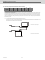
1
Introduction
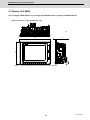
This manual describes the specifications of MITSUBISHI CNC M800/M80 Series.
To safely use this CNC unit, thoroughly study the "Precautions for Safety" on the next page before use.
Details described in this manual
At the beginning of each item, a table indicating it's specification according to the model.
○ : Standard
△ : Optional
□ : Selection
CAUTION
The items that are not described in this manual must be interpreted as "not possible".
This manual is written on the assumption that all option functions are added.
Some functions may differ or some functions may not be usable depending on the NC system (software)
version.
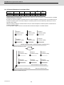
General precautions
(1) When the contents of this manual is updated, the version (A, B, ...) on the cover will be incremented.
Refer to the following documents.
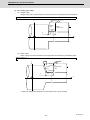
M800W Series Connection and Setup Manual .... IB-1501268
M800S/M80 Series Connection and Setup Manual .... IB-1501269
M800/M80 Series PLC Development Manual .... IB-1501270
M800/M80 Series PLC Programming Manual .... IB-1501271
M800/M80 Series PLC Interface Manual .... IB-1501272
DRIVE SYSTEM DATA BOOK .... IB-1501252
MDS-E/EH Series Specifications Manual .... IB-1501226
MDS-EJ/EJH Series Specifications Manual .... IB-1501232
MDS-EM Series Specifications Manual .... IB-1501238
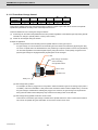
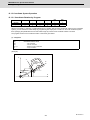
Precautions for Safety
Always read this manual, related manuals and attached documents before installation, operation, programming,
maintenance or inspection to ensure correct use. Understand all the conditions described in this manual before using the
unit. We rank the safety precautions into "DANGER", "WARNING" and "CAUTION" for the manuals issued by Mitsubishi,
including this manual.
DANGER
When there is a great risk that the user could be subject to fatalities or serious injuries if handling is
mistaken.
WARNING
When the user could be subject to fatalities or serious injuries if handling is mistaken.
CAUTION
When the user could be subject to injuries or when physical damage could occur if handling is mistaken.
Note that even items ranked as "
CAUTION", may lead to major results depending on the situation. In any case,
important information that must always be observed is described.
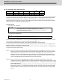
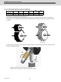
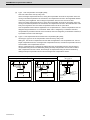
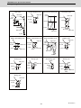
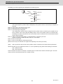
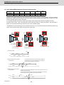
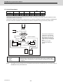
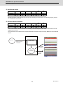
The following signs indicate prohibition and compulsory.
This sign indicates prohibited behavior (must not do).
For example,
indicates "Keep fire away".
This sign indicated a thing that is pompously (must do).
For example,
indicates "it must be grounded".
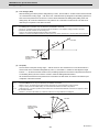
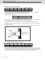
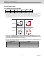
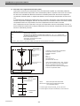
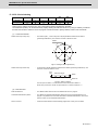
The meaning of each pictorial sign is as follows.
CAUTION
CAUTION rotated
object
CAUTION HOT
Danger Electric shock
risk
Danger explosive
Prohibited
Disassembly is
prohibited
KEEP FIRE AWAY
General instruction
Earth ground
DANGER
Not applicable in this manual.
WARNING
Not applicable in this manual.
CAUTION
1. Items related to product and manual
The items that are not described in this manual must be interpreted as "not possible".
This manual is written on the assumption that all option functions are added.
Some functions may differ or some functions may not be usable depending on the NC system (software)
version.
2. Items related to start up and maintenance
Follow the power specifications (input voltage range, frequency range, momentary power failure time
range) described in this manual.
Follow the environment conditions (ambient temperature, humidity, vibration, atmosphere) described in
this manual.
Follow the remote type machine contact input/output interface described in this manual. (Connect a diode
in parallel with the inductive load or connect a protective resistor in serial with the capacitive load, etc.)
If the parameter is used to set the temperature rise detection function to invalid, overheating may occur,
thereby disabling control and possibly resulting in the axes running out of control, which in turn may result
in machine damage and/or bodily injury or destruction of the unit. It is for this reason that the detection
function is normally left "valid" for operation.The parameter for the temperature rise detection function will
be validated forcibly when the NC unit is turned ON.
Treatment of waste
The following two laws will apply when disposing of this product. Considerations must be made to each law.
The following laws are in effect in Japan. Thus, when using this product overseas, the local laws will have a
priority. If necessary, indicate or notify these laws to the final user of the product.
(1) Requirements for "Law for Promotion of Effective Utilization of Resources"
(a) Recycle as much of this product as possible when finished with use.
(b) When recycling, often parts are sorted into steel scraps and electric parts, etc., and sold to scrap
contractors. Mitsubishi recommends sorting the product and selling the members to appropriate
contractors.
(2) Requirements for "Law for Treatment of Waste and Cleaning"
(a) Mitsubishi recommends recycling and selling the product when no longer needed according to item
(1) above. The user should make an effort to reduce waste in this manner.
(b) When disposing a product that cannot be resold, it shall be treated as a waste product.
(c) The treatment of industrial waste must be commissioned to a licensed industrial waste treatment
contractor, and appropriate measures, including a manifest control, must be taken.
(d) Batteries correspond to "primary batteries", and must be disposed of according to local disposal
laws.
Disposal
(Note)
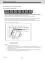
This symbol mark is for EU countries only.
This symbol mark is according to the directive 2006/66/EC Article 20 Information for endusers and Annex II.
Your MITSUBISHI ELECTRIC product is designed and manufactured with high quality materials and
components which can be recycled and/or reused.
This symbol means that batteries and accumulators, at their end-of-life, should be disposed of
separately from your household waste.
If a chemical symbol is printed beneath the symbol shown above, this chemical symbol means that the
battery or accumulator contains a heavy metal at a certain concentration. This will be indicated as
follows:
Hg: mercury (0,0005%), Cd: cadmium (0,002%), Pb: lead (0,004%)
In the European Union there are separate collection systems for used batteries and accumulators.
Please, dispose of batteries and accumulators correctly at your local community waste collection/
recycling centre.
Please, help us to conserve the environment we live in!
Trademarks
MELDAS, MELSEC, EZSocket, EZMotion, iQ Platform, MELSOFT, GOT, CC-Link, CC-Link/LT and CC-Link
IE are either trademarks or registered trademarks of Mitsubishi Electric Corporation in Japan and/or other
countries.
Ethernet is a registered trademark of Xerox Corporation in the United States and/or other countries.
Microsoft® and Windows® are either trademarks or registered trademarks of Microsoft Corporation in the
United States and/or other countries.
SD logo and SDHC logo are either registered trademarks or trademarks of LLC.
UNIX is a registered trademark of The Open Group in the United States and/or other countries.
Intel® and Pentium® are either trademarks or registered trademarks of Intel Corporation in the United States
and/or other countries.
MODBUS® is either trademark or registered trademark of Schneider Electric USA, Inc. or the affiliated
companies in Japan and/or other countries.
Other company and product names that appear in this manual are trademarks or registered trademarks of the
respective companies.
本製品の取扱いについて
( 日本語 /Japanese)
本製品は工業用 ( クラス A) 電磁環境適合機器です。販売者あるいは使用者はこの点に注意し、住商業環境以外で
の使用をお願いいたします。
Handling of our product
(English)
This is a class A product. In a domestic environment this product may cause radio interference in which case the
user may be required to take adequate measures.
본 제품의 취급에 대해서
( 한국어 /Korean)
이 기기는 업무용 (A 급 ) 전자파적합기기로서 판매자 또는 사용자는 이 점을 주의하시기 바라며 가정외의 지역에
서 사용하는 것을 목적으로 합니다 .
WARRANTY
Please confirm the following product warranty details before using MITSUBISHI CNC.
1. Warranty Period and Coverage
Should any fault or defect (hereafter called "failure") for which we are liable occur in this product during the warranty period,
we shall provide repair services at no cost through the distributor from which the product was purchased or through a
Mitsubishi Electric service provider. Note, however that this shall not apply if the customer was informed prior to purchase of
the product that the product is not covered under warranty. Also note that we are not responsible for any on-site readjustment
and/or trial run that may be required after a defective unit is replaced.
[Warranty Term]
The term of warranty for this product shall be twenty-four (24) months from the date of delivery of product to the end user,
provided the product purchased from us in Japan is installed in Japan (but in no event longer than thirty (30) months,
Including the distribution time after shipment from Mitsubishi Electric or its distributor).
Note that, for the case where the product purchased from us in or outside Japan is exported and installed in any country
other than where it was purchased; please refer to "2. Service in overseas countries" as will be explained.
[Limitations]
(1) The customer is requested to conduct an initial failure diagnosis by him/herself, as a general rule. It can also be carried
out by us or our service provider upon the customer’s request and the actual cost will be charged.
(2) This warranty applies only when the conditions, method, environment, etc., of use are in compliance with the terms and
conditions and instructions that are set forth in the instruction manual, user’s manual, and the caution label affixed to the
product, etc.
(3) Even during the term of warranty, repair costs shall be charged to the customer in the following cases:
(a) a failure caused by improper storage or handling, carelessness or negligence, etc., or a failure caused by the
customer’s hardware or software problem
(b) a failure caused by any alteration, etc., to the product made by the customer without Mitsubishi Electric’s approval
(c) a failure which may be regarded as avoidable, if the customer’s equipment in which this product is incorporated is
equipped with a safety device required by applicable laws or has any function or structure considered to be
indispensable in the light of common sense in the industry
(d) a failure which may be regarded as avoidable if consumable parts designated in the instruction manual, etc. are duly
maintained and replaced
(e) any replacement of consumable parts (including a battery, relay and fuse)
(f) a failure caused by external factors such as inevitable accidents, including without limitation fire and abnormal
fluctuation of voltage, and acts of God, including without limitation earthquake, lightning, and natural disasters
(g) a failure which is unforeseeable under technologies available at the time of shipment of this product from our company
(h) any other failures which we are not responsible for or which the customer acknowledges we are not responsible for
2. Service in Overseas Countries
If the customer installs the product purchased from us in his/her machine or equipment, and export it to any country other
than where he/she bought it, the customer may sign a paid warranty contract with our local FA center.
This falls under the case where the product purchased from us in or outside Japan is exported and installed in any country
other than where it was purchased.
For details please contact the distributor from which the customer purchased the product.
3. Exclusion of Responsibility for Compensation against Loss of Opportunity, Secondary Loss, etc.
Whether during or after the term of warranty, we assume no responsibility for any damages arising from causes for which we
are not responsible, any losses of opportunity and/or profit incurred by the customer due to a failure of this product, any
damages, secondary damages or compensation for accidents arising under specific circumstances that either foreseen or
unforeseen by Mitsubishi Electric, any damages to products other than this product, or compensation for any replacement
work, readjustment and startup test run of on-site machines or any other operations conducted by the customer.
4. Changes in Product Specifications
Specifications shown in our catalogs, manuals or technical documents are subject to change without notice.
5. Product Application
(1) For the use of this product, its applications should be those that may not result in a serious damage even if any failure or
malfunction occurs in the product, and a backup or fail-safe function should operate on an external system to the product
when any failure or malfunction occurs.
(2) Mitsubishi CNC is designed and manufactured solely for applications to machine tools to be used for industrial purposes.
Do not use this product in any applications other than those specified above, especially those which are substantially
influential on the public interest or which are expected to have significant influence on human lives or properties.
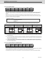
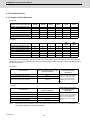
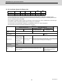
CONTENTS
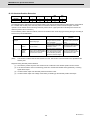
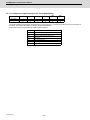
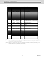
MITSUBISHI CNC M800/M80 Series Specifications List
○: Standard △: Option □: Selection
Lathe system
Class
M800W Series
M800S Series
M80 Series
Page
M850W
M830W
M850S
M830S
M80 TypeA
M80 TypeB
○ 2
○16
△32
○16
△32
8
○ 2
○16
△32
○16
△32
8
○ 2
○16
△32
○16
△32
8
○ 2
○ 2
4
12
9
4
10
7
4
1.1.2.2 Max. Number of Spindles
○ 2
○16
△32
○16
△32
8
4
3
4
1.1.2.3 Max. Number of PLC Axes
1 Control Axes
3
1.1 Control Axes
1.1.1 Number of Basic Control Axes (NC Axes)
1.1.2 Max. Number of Axes (NC Axes + Spindles + PLC Axes)
1.1.2.1 Max. Number of NC Axes (In Total for All the Part Systems)
4
8
8
8
8
6
6
4
1.1.4 Max. Number of PLC Indexing Axes
8
8
8
8
4
4
5
1.1.5 Number of Simultaneous Contouring Control Axes
8
4
8
4
4
4
5
1.1.6 Max. Number of NC Axes in a Part System
8
8
8
8
8
5
5
1
○4
△8
1
○4
△8
1
○4
△8
1
○4
△8
1
1
6
○3
○2
6
1.3.1 Tape (RS-232C Input) Mode
○
○
○
○
○
○
7
1.3.2 Memory Mode
○
○
○
○
○
○
7
1.3.3 MDI Mode
1.2 Control Part System
1.2.1 Standard Number of Part Systems
1.2.2 Max. Number of Part Systems
6
1.3 Control Axes and Operation Modes
7
○
○
○
○
○
○
7
1.3.4.1 Control Unit-side High-speed Program Server Mode
△
△
―
―
―
―
7
1.3.4.2 Display Unit-side High-speed Program Server Mode
△
△
△
△
○
○
8
○
○
○
○
○
○
1.3.4 High-Speed Program Server Mode
1.3.5 Front-side SD card mode
7
2 Input Command
8
9
2.1 Data Increment
10
2.1.1 Least Command Increment
10
Least command increment 1µm
○
○
○
○
○
○
10
Least command increment 0.1µm
○
○
○
○
○
○
10
Least command increment 0.01µm(10nm)
△
△
△
△
―
―
10
Least command increment 0.001µm(1nm)
△
△
△
△
―
―
10
Least control increment 0.01μm(10nm)
○
○
○
○
○
○
12
Least control increment 0.001μm(1nm)
○
○
○
○
○
○
12
○
○
○
○
―
―
2.1.2 Least Control Increment
2.1.3 Indexing Increment
12
2.2 Unit System
13
14
2.2.1 Inch/Metric Changeover
○
○
○
○
○
○
2.2.2 Input Command Increment Tenfold
―
―
―
―
―
―
2.3 Program Format
14
14
15
2.3.1 Program Format
15
2.3.1.1 Format 1 for Lathe (G Code List 2, 3)
○
○
○
○
○
○
15
2.3.1.2 Format 2 for Lathe (G Code List 4, 5)
○
○
○
○
○
○
15
2.3.1.3 Special Format for Lathe (G Code List 6, 7)
○
○
○
○
○
○
15
2.3.1.4 Format 1 for Machining Center
―
―
―
―
―
―
15
2.3.1.5 Format 2 for Machining Center (M2 Format)
―
―
―
―
―
―
2.3.1.6 MITSUBISHI CNC Special Format
○
○
○
○
○
○
2.4 Command Value
2.4.1 Decimal Point Input I, II
15
15
16
○
○
○
○
○
○
16
2.4.2 Absolute/Incremental Command
○
○
○
○
○
○
17
2.4.3 Diameter/Radius Designation
○
○
○
○
○
○
18
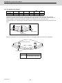
3.1.1 Positioning
○
○
○
○
○
○
20
3.1.2 Unidirectional Positioning
―
―
―
―
―
―
21
3 Positioning/Interpolation
19
3.1 Positioning
20
3.2 Linear/Circular Interpolation
22
3.2.1 Linear Interpolation
○
○
○
○
○
○
3.2.2 Circular Interpolation (Center/Radius Designation)
○
○
○
○
○
○
23
3.2.3 Helical Interpolation
○
○
○
○
○
○
25
3.2.4 Spiral/Conical Interpolation
―
―
―
―
―
―
22
26
3.2.5 Cylindrical Interpolation
△
△
△
△
○
○
28
3.2.6 Polar Coordinate Interpolation
△
△
△
△
○
○
29
3.2.7 Milling Interpolation
△
△
△
△
○
―
30
3.2.8 Hypothetical Axis Interpolation
―
―
―
―
―
―
31
3.3 Curve Interpolation
32
3.3.2 Exponential Interpolation
△
△
△
△
―
―
32
3.3.3 Spline Interpolation (G05.1Q2/G61.2)
―
―
―
―
―
―
33
3.3.4 NURBS Interpolation
―
―
―
―
―
―
34
3.3.5 3-Dimensional Circular Interpolation
―
―
―
―
―
―
35
3.3.6 Spline Interpolation2 (G61.4)
―
―
―
―
―
―
36
○: Standard △: Option □: Selection
Machining center system
Class
M800W Series
M800S Series
M80 Series
Page
M850W
M830W
M850S
M830S
M80 TypeA
M80 TypeB
○ 3
○16
△32
○ 3
○16
△32
○ 3
○16
△32
○ 3
○16
△32
○ 3
○ 3
4
11
9
4
○16
○16
○16
○16
8
5
4
1.1.2.2 Max. Number of Spindles
4
4
4
4
2
2
4
1.1.2.3 Max. Number of PLC Axes
1 Control Axes
3
1.1 Control Axes
1.1.1 Number of Basic Control Axes (NC Axes)
1.1.2 Max. Number of Axes (NC Axes + Spindles + PLC Axes)
1.1.2.1 Max. Number of NC Axes (In Total for All the Part Systems)
4
8
8
8
8
6
6
4
1.1.4 Max. Number of PLC Indexing Axes
8
8
8
8
4
4
5
1.1.5 Number of Simultaneous Contouring Control Axes
8
4
8
4
4
4
5
1.1.6 Max. Number of NC Axes in a Part System
8
8
8
8
8
5
5
1
1
1
1
1
1
6
○2
○2
○2
○2
○2
○1
6
1.3.1 Tape (RS-232C Input) Mode
○
○
○
○
○
○
7
1.3.2 Memory Mode
○
○
○
○
○
○
7
1.3.3 MDI Mode
1.2 Control Part System
1.2.1 Standard Number of Part Systems
1.2.2 Max. Number of Part Systems
6
1.3 Control Axes and Operation Modes
7
○
○
○
○
○
○
7
1.3.4.1 Control Unit-side High-speed Program Server Mode
△
△
―
―
―
―
7
1.3.4.2 Display Unit-side High-speed Program Server Mode
△
△
△
△
○
○
8
○
○
○
○
○
○
1.3.4 High-Speed Program Server Mode
1.3.5 Front-side SD card mode
7
2 Input Command
10
2.1.1 Least Command Increment
Least command increment 1µm
8
9
2.1 Data Increment
10
○
○
○
○
○
○
10
Least command increment 0.1µm
○
○
○
○
○
○
10
Least command increment 0.01µm(10nm)
△
△
△
△
―
―
10
Least command increment 0.001µm(1nm)
△
△
△
△
―
―
2.1.2 Least Control Increment
Least control increment 0.01μm(10nm)
Least control increment 0.001μm(1nm)
2.1.3 Indexing Increment
10
12
○
○
○
○
○
○
12
○
○
○
○
○
○
12
○
○
○
○
―
―
13
2.2 Unit System
14
2.2.1 Inch/Metric Changeover
○
○
○
○
○
○
2.2.2 Input Command Increment Tenfold
○
○
○
○
○
○
2.3 Program Format
14
14
15
2.3.1 Program Format
15
2.3.1.1 Format 1 for Lathe (G Code List 2, 3)
―
―
―
―
―
―
15
2.3.1.2 Format 2 for Lathe (G Code List 4, 5)
―
―
―
―
―
―
15
2.3.1.3 Special Format for Lathe (G Code List 6, 7)
―
―
―
―
―
―
15
2.3.1.4 Format 1 for Machining Center
○
○
○
○
○
○
15
2.3.1.5 Format 2 for Machining Center (M2 Format)
○
○
○
○
○
○
2.3.1.6 MITSUBISHI CNC Special Format
―
―
―
―
―
―
2.4 Command Value
2.4.1 Decimal Point Input I, II
15
15
16
○
16
2.4.2 Absolute/Incremental Command
○
○
○
○
○
○
17
2.4.3 Diameter/Radius Designation
―
○
―
○
―
○
―
○
―
○
―
3 Positioning/Interpolation
18
19
3.1 Positioning
20
3.1.1 Positioning
○
○
○
○
○
○
20
3.1.2 Unidirectional Positioning
△
△
△
△
○
○
21
3.2 Linear/Circular Interpolation
22
3.2.1 Linear Interpolation
○
○
○
○
○
○
3.2.2 Circular Interpolation (Center/Radius Designation)
○
○
○
○
○
○
23
3.2.3 Helical Interpolation
○
○
○
○
○
○
25
3.2.4 Spiral/Conical Interpolation
△
△
△
△
○
―
22
26
3.2.5 Cylindrical Interpolation
△
△
△
△
○
○
28
3.2.6 Polar Coordinate Interpolation
△
△
△
△
―
―
29
3.2.7 Milling Interpolation
―
―
―
―
―
―
30
3.2.8 Hypothetical Axis Interpolation
△
△
△
△
―
―
31
3.3 Curve Interpolation
32
3.3.2 Exponential Interpolation
△
△
△
△
―
―
32
3.3.3 Spline Interpolation (G05.1Q2/G61.2)
△
△
△
△
○
―
33
3.3.4 NURBS Interpolation
△
△
△
△
―
―
34
3.3.5 3-Dimensional Circular Interpolation
△
△
△
△
―
―
35
3.3.6 Spline Interpolation2 (G61.4)
△
△
△
△
○
―
36
○: Standard △: Option □: Selection
Lathe system
Class
M800W Series
M850W
M830W
M800S Series
M850S
M830S
M80 Series
M80 TypeA
Page
M80 TypeB
4 Feed
37
4.1 Feedrate
38
4.1.1 Rapid Traverse Rate (m/min)
1000
1000
1000
1000
1000
1000
38
4.1.2 Cutting Feedrate (m/min)
1000
1000
1000
1000
1000
1000
39
4.1.3 Manual Feedrate (m/min)
1000
1000
1000
1000
1000
1000
40
○
○
○
○
○
○
40
4.2.1 Feed per Minute (Asynchronous Feed)
○
○
○
○
○
○
41
4.2.2 Feed per Revolution (Synchronous Feed)
○
○
○
○
○
○
43
4.2.3 Inverse Time Feed
―
―
―
―
―
―
45
4.2.4 F 1-digit Feed
○
○
○
○
○
○
46
4.2.5 Manual Speed Command
△
△
△
△
○
○
47
4.2.7 G00 Feedrate Designation (,F Command)
△
△
△
△
○
―
4.3.1 Rapid Traverse Override
○
○
○
○
○
○
50
4.3.2 Cutting Feed Override
○
○
○
○
○
○
50
4.3.3 2nd Cutting Feed Override
○
○
○
○
○
○
4.3.4 Override Cancel
○
○
○
○
○
○
4.1.4 Rotary Axis Command Speed Tenfold
4.2 Feedrate Input Methods
41
4.3 Override
48
50
4.4 Acceleration/Deceleration
50
51
52
4.4.1 Automatic Acceleration/Deceleration after Interpolation
○
○
○
○
○
○
52
4.4.2 Rapid Traverse Constant Inclination Acceleration/Deceleration
○
○
○
○
○
○
54
4.4.3 Rapid Traverse Constant Inclination Multi-step Acceleration/Deceleration
―
―
―
―
―
―
○
○
○
○
○
○
4.5 Thread Cutting
4.5.1 Thread Cutting (Lead/Thread Number Designation)
4.5.2 Variable Lead Thread Cutting
59
○
○
○
○
○
○
62
○
○
○
○
○
○
63
4.5.3 Synchronous Tapping
4.5.3.1 Synchronous Tapping Cycle
58
59
63
4.5.3.2 Pecking Tapping Cycle
△
△
△
△
○
○
65
4.5.3.3 Deep-hole Tapping Cycle
△
△
△
△
○
○
67
4.5.4 Chamfering
○
○
○
○
○
○
69
4.5.6 Circular Thread Cutting
△
△
△
△
―
―
70
4.5.8 High-speed Synchronous Tapping (OMR-DD)
○
○
○
○
○
○
71
4.5.10 Thread Recutting
△
△
△
△
○
―
72
4.5.11 Thread Cutting Override
△
△
△
△
○
―
73
4.5.12 Variable Feed Thread Cutting
△
△
△
△
○
―
73
4.5.13 Thread Cutting Time Constant Switch
○
○
○
○
○
○
○
○
○
○
○
○
4.6 Manual Feed
4.6.1 Manual Rapid Traverse
74
75
75
4.6.2 Jog Feed
○
○
○
○
○
○
75
4.6.3 Incremental Feed
○
○
○
○
○
○
76
4.6.4 Handle Feed
○
○
○
○
○
○
76
4.6.5 Manual Feedrate B
○
○
○
○
○
○
77
4.6.6 Manual Feedrate B Surface Speed Control
―
―
―
―
―
―
78
○
○
○
○
○
○
4.7.1 Dwell (Time-based Designation)
4.6.8 Manual Speed Clamp
○
○
○
○
○
○
4.7.2 Dwell (Revolution-based Designation)
○
○
○
○
○
○
4.7 Dwell
79
80
5 Program Memory/Editing
80
81
83
5.1 Memory Capacity
84
5.1.1 Memory Capacity (Number of Programs Stored)
84
230kB[600m] (400 programs)
○
○
○
○
○
○
84
500kB[1280m] (1000 programs)
△
△
△
△
―
―
84
1000kB[2560m] (1000 programs)
△
△
△
△
―
―
○
○
○
○
○
○
2000kB[5120m] (1000 programs)
5.2.1 Program Editing
5.2.2 Background Editing
84
85
○
○
○
○
○
○
85
86
5.2.3 Buffer Correction
○
○
○
○
○
○
87
5.2.5 Multi-part System Simultaneous Program Editing
○
○
○
○
○
○
88
5.2.6 Special Program Editing Display for Synchronization between Part Systems
△
△
△
△
○
○
88
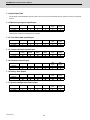
○: Standard △: Option □: Selection
Machining center system
Class
M800W Series
M850W
M830W
M800S Series
M850S
M830S
M80 Series
M80 TypeA
Page
M80 TypeB
4 Feed
37
4.1 Feedrate
38
4.1.1 Rapid Traverse Rate (m/min)
1000
1000
1000
1000
1000
1000
38
4.1.2 Cutting Feedrate (m/min)
1000
1000
1000
1000
1000
1000
39
4.1.3 Manual Feedrate (m/min)
1000
1000
1000
1000
1000
1000
40
○
○
○
○
○
○
40
4.2.1 Feed per Minute (Asynchronous Feed)
○
○
○
○
○
○
41
4.2.2 Feed per Revolution (Synchronous Feed)
△
△
△
△
○
○
43
4.2.3 Inverse Time Feed
△
△
△
△
○
―
45
4.2.4 F 1-digit Feed
○
○
○
○
○
○
46
4.2.5 Manual Speed Command
△
△
△
△
○
○
47
4.2.7 G00 Feedrate Designation (,F Command)
△
△
△
△
○
―
4.3.1 Rapid Traverse Override
○
○
○
○
○
○
50
4.3.2 Cutting Feed Override
○
○
○
○
○
○
50
4.3.3 2nd Cutting Feed Override
○
○
○
○
○
○
4.3.4 Override Cancel
○
○
○
○
○
○
4.1.4 Rotary Axis Command Speed Tenfold
4.2 Feedrate Input Methods
41
4.3 Override
48
50
4.4 Acceleration/Deceleration
50
51
52
4.4.1 Automatic Acceleration/Deceleration after Interpolation
○
○
○
○
○
○
52
4.4.2 Rapid Traverse Constant Inclination Acceleration/Deceleration
○
○
○
○
○
○
54
4.4.3 Rapid Traverse Constant Inclination Multi-step Acceleration/Deceleration
△
△
△
△
○
○
△
△
△
△
○
○
4.5 Thread Cutting
4.5.1 Thread Cutting (Lead/Thread Number Designation)
4.5.2 Variable Lead Thread Cutting
59
―
―
―
―
―
―
62
○
○
○
○
○
○
63
4.5.3 Synchronous Tapping
4.5.3.1 Synchronous Tapping Cycle
58
59
63
4.5.3.2 Pecking Tapping Cycle
△
△
△
△
○
○
65
4.5.3.3 Deep-hole Tapping Cycle
△
△
△
△
○
○
67
4.5.4 Chamfering
―
―
―
―
―
―
69
4.5.6 Circular Thread Cutting
―
―
―
―
―
―
70
4.5.8 High-speed Synchronous Tapping (OMR-DD)
○
○
○
○
○
○
71
4.5.10 Thread Recutting
―
―
―
―
―
―
72
4.5.11 Thread Cutting Override
―
―
―
―
―
―
73
4.5.12 Variable Feed Thread Cutting
―
―
―
―
―
―
73
4.5.13 Thread Cutting Time Constant Switch
○
○
○
○
○
○
○
○
○
○
○
○
4.6 Manual Feed
4.6.1 Manual Rapid Traverse
74
75
75
4.6.2 Jog Feed
○
○
○
○
○
○
75
4.6.3 Incremental Feed
○
○
○
○
○
○
76
4.6.4 Handle Feed
○
○
○
○
○
○
76
4.6.5 Manual Feedrate B
○
○
○
○
○
○
77
4.6.6 Manual Feedrate B Surface Speed Control
△
△
△
△
―
―
78
○
○
○
○
○
○
4.7.1 Dwell (Time-based Designation)
4.6.8 Manual Speed Clamp
○
○
○
○
○
○
4.7.2 Dwell (Revolution-based Designation)
―
―
―
―
―
―
4.7 Dwell
79
80
5 Program Memory/Editing
80
81
83
5.1 Memory Capacity
84
5.1.1 Memory Capacity (Number of Programs Stored)
84
230kB[600m] (400 programs)
○
○
○
○
○
○
84
500kB[1280m] (1000 programs)
△
△
△
△
―
―
84
1000kB[2560m] (1000 programs)
△
△
△
△
―
―
○
○
○
○
○
○
2000kB[5120m] (1000 programs)
5.2.1 Program Editing
5.2.2 Background Editing
84
85
○
○
○
○
○
○
85
86
5.2.3 Buffer Correction
○
○
○
○
○
○
87
5.2.5 Multi-part System Simultaneous Program Editing
○
○
○
○
―
―
88
5.2.6 Special Program Editing Display for Synchronization between Part Systems
△
△
△
△
―
―
88
○: Standard △: Option □: Selection
Lathe system
Class
M800W Series
M850W
M830W
M800S Series
M850S
M830S
M80 Series
M80 TypeA
Page
M80 TypeB
6 Operation and Display
89
6.1 Structure of Operation/Display Panel
90
6.1.1 Color Display(8.4-type LCD TFT)
―
―
―
―
□
□
90
6.1.2 Color touchscreen Display (10.4-type LCD TFT)
―
―
□
□
□
□
90
6.1.3 Color touchscreen Display (15-type LCD TFT)
―
―
□
□
□
□
90
6.1.6 Color touchscreen display(15-type LCD TFT/Windows8)
□
□
―
―
―
―
6.1.7 Color touchscreen Display (19-type LCD TFT/Windows8)
□
□
―
―
―
―
6.2 Operation Methods and Functions
90
90
91
6.2.1 Operation Input
○
○
○
○
○
○
91
6.2.2 Absolute Value/Incremental Value Setting
○
○
○
○
○
○
91
6.2.5 Displayed Part System Switch
○
○
○
○
○
○
91
6.2.6 Menu List
○
○
○
○
○
○
92
6.2.7 Display Switch by Operation Mode
○
○
○
○
○
○
92
6.2.8 External Signal Display Switch
○
○
○
○
○
―
92
6.2.9 Screen Saver
○
○
○
○
○
○
92
6.2.10 Parameter Guidance
○
○
○
○
○
○
92
6.2.11 Alarm Guidance
○
○
○
○
○
○
93
6.2.12 Machining Program Input Mistake Check Warning
△
△
△
△
―
―
93
6.2.14 Screenshot Capture
―
―
○
○
○
○
93
6.2.15 User Selectable Menu Configuration
○
○
○
○
○
○
93
6.2.16 PC-NC Network Automatic Connection
○
○
―
―
―
―
94
6.2.17 Device Open Parameter
○
○
○
○
○
○
94
6.2.18 SRAM Open Parameter
○
○
○
○
○
○
94
6.2.19 MTB Selectable Menu Configuration
○
○
○
○
○
○
6.3 Display Methods and Contents
94
95
6.3.1 Status Display
○
○
○
○
○
○
95
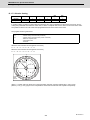
6.3.2 Clock Display
○
○
○
○
○
○
95
6.3.3 Monitor Screen Display
○
○
○
○
○
○
96
6.3.4 Setup Screen Display
○
○
○
○
○
○
97
6.3.5 Edit Screen Display
○
○
○
○
○
○
97
6.3.6 Diagnosis Screen Display
○
○
○
○
○
○
97
6.3.7 Maintenance Screen Display
○
○
○
○
○
○
98
6.3.8 Home Application
○
○
―
―
―
―
98
6.3.10.1 Japanese
□
□
□
□
□
□
99
6.3.10.2 English
○
○
○
○
○
○
99
6.3.10.3 German
□
□
□
□
□
□
99
6.3.10.4 Italian
□
□
□
□
□
□
99
6.3.10.5 French
□
□
□
□
□
□
99
6.3.10.6 Spanish
□
□
□
□
□
□
99
6.3.10.7.1 Chinese (Traditional Chinese Characters)
□
□
□
□
□
□
99
6.3.10.7.2 Chinese (Simplified Chinese Characters)
□
□
□
□
□
□
99
6.3.10.8 Korean
□
□
□
□
□
□
100
6.3.10.9 Portuguese
□
□
□
□
□
□
100
6.3.10.10 Hungarian
□
□
□
□
□
□
100
6.3.10.11 Dutch
□
□
□
□
□
□
100
6.3.10.12 Swedish
□
□
□
□
□
□
100
6.3.10.13 Turkish
□
□
□
□
□
□
100
6.3.10.14 Polish
□
□
□
□
□
□
100
6.3.10.15 Russian
□
□
□
□
□
□
100
6.3.10.16 Czech
□
□
□
□
□
□
100
7.1.1 Machining Program Input/Output
○
○
○
○
○
○
102
7.1.2 Tool Offset Data Input/Output
○
○
○
○
○
○
102
6.3.10 Additional Languages
99
6.3.10.7 Chinese
99
7 Input/Output Functions and Devices
101
7.1 Input/Output Data
7.1.3 Common Variable Input/Output
102
○
○
○
○
○
○
102
7.1.4 Parameter Input/Output
○
○
○
○
○
○
102
7.1.5 History Data Output
○
○
○
○
○
○
102
7.1.7 System Configuration Data Output
○
○
○
○
○
○
○
○
○
○
○
○
7.2 Input/Output I/F
7.2.1 RS-232C I/F
102
103
7.2.2 SD Card I/F
103
103
7.2.2.1 Control Unit-side SD Card I/F [Up to 32GB]
○
○
―
―
―
―
103
7.2.2.2 Front-side SD Card I/F [Up to 32GB]
○
○
○
○
○
○
103
7.2.3 Ethernet I/F
○
○
○
○
○
○
103
7.2.4 Display Unit-side Data Server I/F
○
○
○
○
○
○
104
7.2.5 Front-side USB Memory I/F [Up to 32GB]
○
○
○
○
○
○
△
△
△
△
○
○
7.3 Computer Link
7.3.1 Computer Link B
104
105
105
○: Standard △: Option □: Selection
Machining center system
Class
M800W Series
M850W
M830W
M800S Series
M850S
M830S
M80 Series
M80 TypeA
Page
M80 TypeB
6 Operation and Display
89
6.1 Structure of Operation/Display Panel
90
6.1.1 Color Display(8.4-type LCD TFT)
―
―
―
―
□
□
90
6.1.2 Color touchscreen Display (10.4-type LCD TFT)
―
―
□
□
□
□
90
6.1.3 Color touchscreen Display (15-type LCD TFT)
―
―
□
□
□
□
90
6.1.6 Color touchscreen display(15-type LCD TFT/Windows8)
□
□
―
―
―
―
6.1.7 Color touchscreen Display (19-type LCD TFT/Windows8)
□
□
―
―
―
―
6.2 Operation Methods and Functions
90
90
91
6.2.1 Operation Input
○
○
○
○
○
○
91
6.2.2 Absolute Value/Incremental Value Setting
○
○
○
○
○
○
91
6.2.5 Displayed Part System Switch
○
○
○
○
○
―
91
6.2.6 Menu List
○
○
○
○
○
○
92
6.2.7 Display Switch by Operation Mode
○
○
○
○
○
○
92
6.2.8 External Signal Display Switch
○
○
○
○
○
―
92
6.2.9 Screen Saver
○
○
○
○
○
○
92
6.2.10 Parameter Guidance
○
○
○
○
○
○
92
6.2.11 Alarm Guidance
○
○
○
○
○
○
93
6.2.12 Machining Program Input Mistake Check Warning
△
△
△
△
―
―
93
6.2.14 Screenshot Capture
―
―
○
○
○
○
93
6.2.15 User Selectable Menu Configuration
○
○
○
○
○
○
93
6.2.16 PC-NC Network Automatic Connection
○
○
―
―
―
―
94
6.2.17 Device Open Parameter
○
○
○
○
○
○
94
6.2.18 SRAM Open Parameter
○
○
○
○
○
○
94
6.2.19 MTB Selectable Menu Configuration
○
○
○
○
○
○
6.3 Display Methods and Contents
94
95
6.3.1 Status Display
○
○
○
○
○
○
95
6.3.2 Clock Display
○
○
○
○
○
○
95
6.3.3 Monitor Screen Display
○
○
○
○
○
○
96
6.3.4 Setup Screen Display
○
○
○
○
○
○
97
6.3.5 Edit Screen Display
○
○
○
○
○
○
97
6.3.6 Diagnosis Screen Display
○
○
○
○
○
○
97
6.3.7 Maintenance Screen Display
○
○
○
○
○
○
98
6.3.8 Home Application
○
○
―
―
―
―
98
6.3.10.1 Japanese
□
□
□
□
□
□
99
6.3.10.2 English
○
○
○
○
○
○
99
6.3.10.3 German
□
□
□
□
□
□
99
6.3.10.4 Italian
□
□
□
□
□
□
99
6.3.10.5 French
□
□
□
□
□
□
99
6.3.10.6 Spanish
□
□
□
□
□
□
99
6.3.10.7.1 Chinese (Traditional Chinese Characters)
□
□
□
□
□
□
99
6.3.10.7.2 Chinese (Simplified Chinese Characters)
□
□
□
□
□
□
99
6.3.10.8 Korean
□
□
□
□
□
□
100
6.3.10.9 Portuguese
□
□
□
□
□
□
100
6.3.10.10 Hungarian
□
□
□
□
□
□
100
6.3.10.11 Dutch
□
□
□
□
□
□
100
6.3.10.12 Swedish
□
□
□
□
□
□
100
6.3.10.13 Turkish
□
□
□
□
□
□
100
6.3.10.14 Polish
□
□
□
□
□
□
100
6.3.10.15 Russian
□
□
□
□
□
□
100
6.3.10.16 Czech
□
□
□
□
□
□
100
7.1.1 Machining Program Input/Output
○
○
○
○
○
○
102
7.1.2 Tool Offset Data Input/Output
○
○
○
○
○
○
102
6.3.10 Additional Languages
99
6.3.10.7 Chinese
99
7 Input/Output Functions and Devices
101
7.1 Input/Output Data
7.1.3 Common Variable Input/Output
102
○
○
○
○
○
○
102
7.1.4 Parameter Input/Output
○
○
○
○
○
○
102
7.1.5 History Data Output
○
○
○
○
○
○
102
7.1.7 System Configuration Data Output
○
○
○
○
○
○
○
○
○
○
○
○
7.2 Input/Output I/F
7.2.1 RS-232C I/F
102
103
7.2.2 SD Card I/F
103
103
7.2.2.1 Control Unit-side SD Card I/F [Up to 32GB]
○
○
―
―
―
―
103
7.2.2.2 Front-side SD Card I/F [Up to 32GB]
○
○
○
○
○
○
103
7.2.3 Ethernet I/F
○
○
○
○
○
○
103
7.2.4 Display Unit-side Data Server I/F
○
○
○
○
○
○
104
7.2.5 Front-side USB Memory I/F [Up to 32GB]
○
○
○
○
○
○
△
△
△
△
○
○
7.3 Computer Link
7.3.1 Computer Link B
104
105
105
○: Standard △: Option □: Selection
Lathe system
Class
M800W Series
M850W
M830W
M800S Series
M850S
M830S
M80 Series
M80 TypeA
Page
M80 TypeB
8 Spindle, Tool and Miscellaneous Functions
107
8.1 Spindle Functions (S)
108
8.1.1 Spindle Control Functions
108
8.1.1.1 Spindle Digital I/F
○
○
○
○
○
○
109
8.1.1.2 Spindle Analog I/F
○
○
○
○
○
○
109
8.1.1.3 Coil Switch
○
○
○
○
○
○
109
8.1.1.4 Automatic Coil Switch
○
○
○
○
○
○
109
8.1.1.5 Encoder Input I/F
―
―
○
○
○
○
110
8.1.1.6 Spindle-mode Servo Motor Control
△
△
△
△
○
○
111
8.1.1.8 Turret Gear Change Control
△
△
△
△
―
―
112
8.1.2 S Code Output
○
○
○
○
○
○
113
8.1.3 Constant Surface Speed Control
○
○
○
○
○
○
114
8.1.4 Spindle Override
○
○
○
○
○
○
116
8.1.5.1 Multiple-spindle Control I
○
○
○
○
○
○
117
8.1.5.2 Multiple-spindle Control II
○
○
○
○
○
○
117
8.1.5 Multiple-spindle Control
8.1.6 Spindle Orientation
116
○
○
○
○
○
○
118
8.1.7.1 Spindle Position Control (Spindle/C Axis Control)
○
○
○
○
○
○
119
8.1.7.2 C Axis Control during Spindle Synchronization
△
△
△
△
○
○
120
8.1.8.1 Spindle Synchronization I
○
○
○
○
○
○
121
8.1.8.2 Spindle Synchronization II
○
○
○
○
○
○
122
8.1.8.3 Guide Bushing Spindle Synchronization
△
△
△
△
○
―
122
8.1.9.1 Tool Spindle Synchronization I A (Spindle-Spindle, Polygon)
△
△
△
△
○
○
123
8.1.9.2 Tool Spindle Synchronization I B (Spindle-Spindle, Polygon)
△
△
△
△
○
○
124
8.1.9.3 Tool Spindle Synchronization I C (Spindle-NC Axis, Polygon)
8.1.7 Spindle Position Control (Spindle/C Axis Control)
119
8.1.8 Spindle Synchronization
121
8.1.9 Tool Spindle Synchronization I (Polygon)
123
△
△
△
△
○
―
125
8.1.10 Tool Spindle Synchronization II (Hobbing)
△
△
△
△
○
―
126
8.1.11 Spindle Speed Clamp
○
○
○
○
○
○
127
8.1.13 Spindle Oscillation
△
△
△
△
―
―
127
8.1.14 Spindle Superimposition Control
△
△
△
△
○
―
8.2 Tool Functions (T)
8.2.1 Tool Functions (T Command)
128
130
○
○
○
○
○
○
8.3.1 Miscellaneous Functions
○
○
○
○
○
○
131
8.3.2 Multiple M Codes in 1 Block
○
○
○
○
○
○
131
8.3.3 M Code Independent Output
○
○
○
○
○
○
132
8.3.4 Miscellaneous Function Finish
○
○
○
○
○
○
133
8.3.5 M Code Output during Axis Traveling
○
○
○
○
○
―
8.3.6 Miscellaneous Function Command High-speed Output
○
○
○
○
○
○
8.3 Miscellaneous Functions (M)
130
131
8.4 2nd Miscellaneous Functions (B)
134
135
137
8.4.1 2nd Miscellaneous Functions
○
○
○
○
○
○
8.4.2 2nd Miscellaneous Function Name Extension
○
○
○
○
○
○
9 Tool Compensation
137
137
139
9.1 Tool Length/Tool Position
140
9.1.1 Tool Length Offset
○
○
○
○
○
○
9.1.2 Tool Position Offset
―
―
―
―
―
―
9.1.3 Tool Compensation for Additional Axes
○
○
○
○
○
○
9.2 Tool Radius
140
143
143
144
9.2.1 Tool Radius Compensation
―
―
―
―
―
―
144
9.2.2 3-dimensional Tool Radius Compensation
―
―
―
―
―
―
147
9.2.3 Tool Nose Radius Compensation (G40/41/42)
○
○
○
○
○
○
148
9.2.4 Automatic Decision of Nose Radius Compensation Direction (G46/40)
○
○
○
○
○
○
149
9.2.5 Tool Radius Compensation Diameter Designation
―
―
―
―
―
―
149
99 sets
―
―
―
―
―
○
150
128 sets
○
○
○
○
―
―
150
9.3 Tool Offset Amount
150
9.3.1 Number of Tool Offset Sets
200 sets
150
―
―
―
―
―
―
150
256 sets
―
―
―
―
○
―
150
400 sets
△
△
△
△
―
―
150
999 sets
△
△
△
△
―
―
150
○
○
○
○
○
○
151
○
○
○
○
○
○
9.3.2 Offset Memory
9.3.2.1 Tool Shape/Wear Offset Amount
9.3.3 Number of Tool Offset Sets Allocation to Part Systems (Variable Number of Per-part-system Tool Offset Sets)
151
10 Coordinate System
154
155
10.1 Coordinate System Type and Setting
156
10.1.1 Machine Coordinate System
○
○
○
○
○
○
157
10.1.2 Coordinate System Setting
○
○
○
○
○
○
158
10.1.3 Automatic Coordinate System Setting
○
○
○
○
○
○
160
○
○
○
○
○
○
161
10.1.4 Workpiece Coordinate System Selection
10.1.4.1 Workpiece Coordinate System Selection (6 Sets)
161
10.1.4.2 Extended Workpiece Coordinate System Selection (48 Sets) G54.1P1 to P48
△
△
△
△
○
○
163
10.1.4.3 Extended Workpiece Coordinate System Selection (96 Sets) G54.1P1 to P96
―
―
―
―
―
―
163
10.1.4.4 Extended Workpiece Coordinate System Selection (300 Sets) G54.1P1 to P300
―
―
―
―
―
―
163
10.1.5 External Workpiece Coordinate Offset
○
○
○
○
○
○
164
10.1.6 Workpiece Coordinate System Preset (G92.1)
○
○
○
○
○
○
165
10.1.7 Local Coordinate System
○
○
○
○
○
○
166
10.1.8 Coordinate System for Rotary Axis
○
○
○
○
○
○
167
10.1.9 Plane Selection
○
○
○
○
○
○
168
10.1.10 Origin Set/Origin Cancel
○
○
○
○
○
○
169
10.1.11 Counter Set
○
○
○
○
○
○
171
10.1.13 Workpiece coordinate system shift
○
○
○
○
○
○
○
○
○
○
○
○
10.2 Return
10.2.1 Manual Reference Position Return
10.2.2 Automatic 1st Reference Position Return
172
173
○
○
○
○
○
○
173
174
10.2.3 2nd, 3rd, 4th Reference Position Return
○
○
○
○
○
○
176
10.2.4 Reference Position Check
○
○
○
○
○
○
178
10.2.5 Absolute Position Detection
○
○
○
○
○
○
179
10.2.6 Tool Exchange Position Return
○
○
○
○
○
○
180
○: Standard △: Option □: Selection
Machining center system
Class
M800W Series
M850W
M830W
M800S Series
M850S
M830S
M80 Series
M80 TypeA
Page
M80 TypeB
8 Spindle, Tool and Miscellaneous Functions
107
8.1 Spindle Functions (S)
108
8.1.1 Spindle Control Functions
108
8.1.1.1 Spindle Digital I/F
○
○
○
○
○
○
109
8.1.1.2 Spindle Analog I/F
○
○
○
○
○
○
109
8.1.1.3 Coil Switch
○
○
○
○
○
○
109
8.1.1.4 Automatic Coil Switch
○
○
○
○
○
○
109
8.1.1.5 Encoder Input I/F
―
―
○
○
○
○
110
8.1.1.6 Spindle-mode Servo Motor Control
△
△
△
△
○
○
111
8.1.1.8 Turret Gear Change Control
―
―
―
―
―
―
112
8.1.2 S Code Output
○
○
○
○
○
○
113
8.1.3 Constant Surface Speed Control
○
○
○
○
○
○
114
8.1.4 Spindle Override
○
○
○
○
○
○
116
8.1.5.1 Multiple-spindle Control I
―
―
―
―
―
―
117
8.1.5.2 Multiple-spindle Control II
○
○
○
○
○
○
117
8.1.5 Multiple-spindle Control
8.1.6 Spindle Orientation
116
○
○
○
○
○
○
118
8.1.7.1 Spindle Position Control (Spindle/C Axis Control)
○
○
○
○
○
○
119
8.1.7.2 C Axis Control during Spindle Synchronization
―
―
―
―
―
―
120
8.1.8.1 Spindle Synchronization I
―
―
―
―
―
―
121
8.1.8.2 Spindle Synchronization II
―
―
―
―
―
―
122
8.1.8.3 Guide Bushing Spindle Synchronization
―
―
―
―
―
―
122
8.1.9.1 Tool Spindle Synchronization I A (Spindle-Spindle, Polygon)
―
―
―
―
―
―
123
8.1.9.2 Tool Spindle Synchronization I B (Spindle-Spindle, Polygon)
―
―
―
―
―
―
124
8.1.9.3 Tool Spindle Synchronization I C (Spindle-NC Axis, Polygon)
8.1.7 Spindle Position Control (Spindle/C Axis Control)
119
8.1.8 Spindle Synchronization
121
8.1.9 Tool Spindle Synchronization I (Polygon)
123
―
―
―
―
―
―
125
8.1.10 Tool Spindle Synchronization II (Hobbing)
―
―
―
―
―
―
126
8.1.11 Spindle Speed Clamp
○
○
○
○
○
○
127
8.1.13 Spindle Oscillation
△
△
△
△
―
―
127
8.1.14 Spindle Superimposition Control
―
―
―
―
―
―
8.2 Tool Functions (T)
8.2.1 Tool Functions (T Command)
128
130
○
○
○
○
○
○
8.3.1 Miscellaneous Functions
○
○
○
○
○
○
131
8.3.2 Multiple M Codes in 1 Block
○
○
○
○
○
○
131
8.3.3 M Code Independent Output
○
○
○
○
○
○
132
8.3.4 Miscellaneous Function Finish
○
○
○
○
○
○
133
8.3.5 M Code Output during Axis Traveling
―
―
―
―
―
―
8.3.6 Miscellaneous Function Command High-speed Output
○
○
○
○
○
○
8.3 Miscellaneous Functions (M)
130
131
8.4 2nd Miscellaneous Functions (B)
134
135
137
8.4.1 2nd Miscellaneous Functions
○
○
○
○
○
○
8.4.2 2nd Miscellaneous Function Name Extension
○
○
○
○
○
○
9 Tool Compensation
137
137
139
9.1 Tool Length/Tool Position
140
9.1.1 Tool Length Offset
○
○
○
○
○
○
9.1.2 Tool Position Offset
○
○
○
○
○
○
9.1.3 Tool Compensation for Additional Axes
―
―
―
―
―
―
9.2 Tool Radius
140
143
143
144
9.2.1 Tool Radius Compensation
○
○
○
○
○
○
144
9.2.2 3-dimensional Tool Radius Compensation
△
△
△
△
―
―
147
9.2.3 Tool Nose Radius Compensation (G40/41/42)
―
―
―
―
―
―
148
9.2.4 Automatic Decision of Nose Radius Compensation Direction (G46/40)
―
―
―
―
―
―
149
9.2.5 Tool Radius Compensation Diameter Designation
○
○
○
○
○
○
149
99 sets
―
―
―
―
―
―
150
128 sets
―
―
―
―
―
―
150
9.3 Tool Offset Amount
150
9.3.1 Number of Tool Offset Sets
200 sets
150
○
○
○
○
―
―
150
256 sets
―
―
―
―
―
―
150
400 sets
△
△
△
△
○
○
150
999 sets
△
△
△
△
―
―
150
○
○
○
○
○
○
151
○
○
○
○
―
―
9.3.2 Offset Memory
9.3.2.1 Tool Shape/Wear Offset Amount
9.3.3 Number of Tool Offset Sets Allocation to Part Systems (Variable Number of Per-part-system Tool Offset Sets)
151
10 Coordinate System
154
155
10.1 Coordinate System Type and Setting
156
10.1.1 Machine Coordinate System
○
○
○
○
○
○
157
10.1.2 Coordinate System Setting
○
○
○
○
○
○
158
10.1.3 Automatic Coordinate System Setting
○
○
○
○
○
○
160
○
○
○
○
○
○
161
10.1.4 Workpiece Coordinate System Selection
10.1.4.1 Workpiece Coordinate System Selection (6 Sets)
161
10.1.4.2 Extended Workpiece Coordinate System Selection (48 Sets) G54.1P1 to P48
△
△
△
△
○
○
163
10.1.4.3 Extended Workpiece Coordinate System Selection (96 Sets) G54.1P1 to P96
△
△
△
△
―
―
163
10.1.4.4 Extended Workpiece Coordinate System Selection (300 Sets) G54.1P1 to P300
△
△
△
△
―
―
163
10.1.5 External Workpiece Coordinate Offset
○
○
○
○
○
○
164
10.1.6 Workpiece Coordinate System Preset (G92.1)
△
△
△
△
―
―
165
10.1.7 Local Coordinate System
○
○
○
○
○
○
166
10.1.8 Coordinate System for Rotary Axis
○
○
○
○
○
○
167
10.1.9 Plane Selection
○
○
○
○
○
○
168
10.1.10 Origin Set/Origin Cancel
○
○
○
○
○
○
169
10.1.11 Counter Set
○
○
○
○
○
○
171
10.1.13 Workpiece coordinate system shift
―
―
―
―
―
―
○
○
○
○
○
○
10.2 Return
10.2.1 Manual Reference Position Return
10.2.2 Automatic 1st Reference Position Return
172
173
○
○
○
○
○
○
173
174
10.2.3 2nd, 3rd, 4th Reference Position Return
○
○
○
○
○
○
176
10.2.4 Reference Position Check
○
○
○
○
○
○
178
10.2.5 Absolute Position Detection
○
○
○
○
○
○
179
10.2.6 Tool Exchange Position Return
○
○
○
○
○
○
180
○: Standard △: Option □: Selection
Lathe system
Class
M800W Series
M850W
M830W
M800S Series
M850S
M830S
M80 Series
M80 TypeA
Page
M80 TypeB
11 Operation Support Functions
181
11.1 Program Control
182
11.1.1 Optional Block Skip
○
○
○
○
○
○
182
11.1.2 Optional Block Skip Addition
○
○
○
○
○
○
182
11.1.3 Single Block
○
○
○
○
○
○
11.2 Program Test
183
184
11.2.1 Dry Run
○
○
○
○
○
○
184
11.2.2 Machine Lock
○
○
○
○
○
○
184
11.2.3 Miscellaneous Function Lock
○
○
○
○
○
○
184
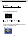
11.2.4.1 Graphic Check
○
○
○
○
○
○
185
11.2.4.2 3D Solid Program Check
○
○
○
○
○
○
185
11.2.4.3 Graphic Check Rotary Axis Drawing
11.2.4 Graphic Check
185
△
△
△
△
○
○
186
11.2.5.1 Graphic Trace
○
○
○
○
○
○
186
11.2.5.2 Graphic Trace Rotary Axis Drawing
△
△
△
△
○
○
187
11.2.5 Graphic Trace
11.2.6 Machining Time Computation
186
○
○
○
○
○
○
187
11.2.7 Manual Arbitrary Reverse Run (Program Check Operation)
△
△
△
△
○
○
188
11.2.8 High-speed Simple Program Check
△
△
△
△
○
○
189
11.3 Program Search/Start/Stop
11.3.1 Program Search
190
○
○
○
○
○
○
190
11.3.2 Sequence Number Search
○
○
○
○
○
○
190
11.3.3 Verification Stop
○
○
○
○
○
○
191
11.3.4 Program Restart
○
○
○
○
○
○
192
11.3.5 Automatic Operation Start
○
○
○
○
○
○
192
11.3.6 NC Reset
○
○
○
○
○
○
193
11.3.7 Feed Hold
○
○
○
○
○
○
193
11.3.8 Search & Start
○
○
○
○
○
○
194
11.3.10 Auto-restart
○
○
○
○
○
○
○
○
○
○
○
○
11.4 Interrupt Operation
11.4.1 Manual Interruption
194
195
195
11.4.2 Automatic Operation Handle Interruption
○
○
○
○
○
○
195
11.4.3 Manual Absolute Switch
○
○
○
○
○
○
196
11.4.4 Thread Cutting Cycle Retract
○
○
○
○
○
○
197
11.4.5 Tapping Retract
○
○
○
○
○
○
198
11.4.6 Manual Numerical Value Command
○
○
○
○
○
○
199
11.4.7 Arbitrary Reverse Run
―
―
―
―
―
―
200
11.4.8 MDI Interruption
○
○
○
○
○
○
201
11.4.9 Simultaneous Operation of Manual and Automatic Modes
○
○
○
○
○
○
201
11.4.10 Simultaneous Operation of JOG and Handle Modes
○
○
○
○
○
○
201
11.4.11 Reference Position Retract
○
○
○
○
○
○
202
11.4.12 Tool Retract and Return
―
―
―
―
―
―
203
11.4.13 Skip Retract
―
―
―
―
―
―
204
11.4.14 PLC Interruption
○
○
○
○
○
○
204
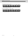
○: Standard △: Option □: Selection
Machining center system
Class
M800W Series
M850W
M830W
M800S Series
M850S
M830S
M80 Series
M80 TypeA
Page
M80 TypeB
11 Operation Support Functions
181
11.1 Program Control
182
11.1.1 Optional Block Skip
○
○
○
○
○
○
182
11.1.2 Optional Block Skip Addition
○
○
○
○
○
○
182
11.1.3 Single Block
○
○
○
○
○
○
11.2 Program Test
183
184
11.2.1 Dry Run
○
○
○
○
○
○
184
11.2.2 Machine Lock
○
○
○
○
○
○
184
11.2.3 Miscellaneous Function Lock
○
○
○
○
○
○
184
11.2.4.1 Graphic Check
○
○
○
○
○
○
185
11.2.4.2 3D Solid Program Check
○
○
○
○
○
○
185
11.2.4.3 Graphic Check Rotary Axis Drawing
11.2.4 Graphic Check
185
―
―
―
―
―
―
186
11.2.5.1 Graphic Trace
○
○
○
○
○
○
186
11.2.5.2 Graphic Trace Rotary Axis Drawing
―
―
―
―
―
―
187
11.2.5 Graphic Trace
11.2.6 Machining Time Computation
186
○
○
○
○
○
○
187
11.2.7 Manual Arbitrary Reverse Run (Program Check Operation)
△
△
△
△
○
○
188
11.2.8 High-speed Simple Program Check
△
△
△
△
○
○
189
11.3 Program Search/Start/Stop
11.3.1 Program Search
190
○
○
○
○
○
○
190
11.3.2 Sequence Number Search
○
○
○
○
○
○
190
11.3.3 Verification Stop
○
○
○
○
○
○
191
11.3.4 Program Restart
○
○
○
○
○
○
192
11.3.5 Automatic Operation Start
○
○
○
○
○
○
192
11.3.6 NC Reset
○
○
○
○
○
○
193
11.3.7 Feed Hold
○
○
○
○
○
○
193
11.3.8 Search & Start
○
○
○
○
○
○
194
11.3.10 Auto-restart
○
○
○
○
○
○
○
○
○
○
○
○
11.4 Interrupt Operation
11.4.1 Manual Interruption
194
195
195
11.4.2 Automatic Operation Handle Interruption
○
○
○
○
○
○
195
11.4.3 Manual Absolute Switch
○
○
○
○
○
○
196
11.4.4 Thread Cutting Cycle Retract
―
―
―
―
―
―
197
11.4.5 Tapping Retract
○
○
○
○
○
○
198
11.4.6 Manual Numerical Value Command
○
○
○
○
○
○
199
11.4.7 Arbitrary Reverse Run
○
○
○
○
○
―
200
11.4.8 MDI Interruption
○
○
○
○
○
○
201
11.4.9 Simultaneous Operation of Manual and Automatic Modes
○
○
○
○
○
○
201
11.4.10 Simultaneous Operation of JOG and Handle Modes
○
○
○
○
○
○
201
11.4.11 Reference Position Retract
○
○
○
○
○
○
202
11.4.12 Tool Retract and Return
△
△
△
△
―
―
203
11.4.13 Skip Retract
○
○
○
○
○
○
204
11.4.14 PLC Interruption
○
○
○
○
○
○
204
○: Standard △: Option □: Selection
Lathe system
Class
M800W Series
M850W
M830W
M800S Series
M850S
M830S
M80 Series
M80 TypeA
Page
M80 TypeB
12 Program Support Functions
205
12.1 Machining Method Support Functions
206
12.1.1 Program
12.1.1.1 Subprogram Control
206
○8重
○8重
○8重
○8重
○8重
○8重
206
12.1.1.2 Figure Rotation
―
―
―
―
―
―
208
12.1.1.3 Scaling
―
―
―
―
―
―
210
12.1.1.4 Axis Name Switch
○
○
○
○
○
○
211
○4重
○4重
○4重
○4重
○4重
○4重
212
12.1.2.2 Machine Tool Builder Macro
○
○
○
○
○
○
215
12.1.2.3 Macro Interruption
12.1.2 Macro Program
12.1.2.1 User Macro
212
○
○
○
○
○
○
216
600 sets
―
―
―
―
―
○
217
700 sets
○
○
○
○
○
―
217
8000 sets
△
△
△
△
―
―
217
(600+100×number of part systems) sets
○
○
○
○
○
―
217
(7900+100×number of part systems) sets
△
△
△
△
―
―
217
12.1.3.1 Fixed Cycle for Drilling
○
○
○
○
○
○
220
12.1.3.2 Fixed Cycle for Drilling (Type II)
○
○
○
○
○
○
225
12.1.3.3 Special Fixed Cycle
―
―
―
―
―
―
226
12.1.3.4 Fixed Cycle for Turning Machining
○
○
○
○
○
○
229
12.1.3.5 Compound Type Fixed Cycle for Turning Machining
△
△
△
△
○
○
234
12.1.3.6 Compound Type Fixed Cycle for Turning Machining (Type II)
△
△
△
△
○
○
243
12.1.3.7 Small-diameter Deep-hole Drilling Cycle
△
△
△
△
―
―
244
12.1.4.1 Mirror Image by Parameter Setting
○
○
○
○
○
○
244
12.1.4.2 Mirror Image by External Input
○
○
○
○
○
○
244
12.1.4.3 Mirror Image by G Code
―
―
―
―
―
―
245
12.1.4.4 Mirror Image for Facing Tool Posts
○
○
○
○
○
―
246
12.1.4.5 T Code Mirror Image for Facing Tool Posts
○
○
○
○
○
―
246
12.1.5.1 Coordinate Rotation by Program
△
△
△
△
○
―
247
12.1.5.2 Coordinate Rotation by Parameter
―
―
―
―
―
―
249
12.1.5.3 3-dimensional Coordinate Conversion
―
―
―
―
―
―
250
12.1.6.1 Corner Chamfering/Corner R
△
△
△
△
○
○
251
12.1.6.2 Linear Angle Command
△
△
△
△
○
○
258
12.1.6.3 Geometric Command
○
○
○
○
○
○
259
12.1.6.4 Polar Coordinate Command
―
―
―
―
―
―
262
△
△
△
△
○
○
263
12.1.7.2 Normal Line Control
―
―
―
―
―
―
264
12.1.7.3 Circular Cutting
―
―
―
―
―
―
265
12.1.8.1 Timing Synchronization between Part Systems
○
○
○
○
○
○
266
12.1.8.2 Start Point Designation Timing Synchronization
12.1.2.4 Variable Command
217
12.1.3 Fixed Cycle
219
12.1.4 Mirror Image
244
12.1.5 Coordinate System Operation
247
12.1.6 Dimension Input
251
12.1.7 Axis Control
263
12.1.7.1 Chopping
12.1.7.1.1 Chopping
263
12.1.8 Multi-part System Control
266
○
○
○
○
○
○
267
12.1.8.3.1 Mixed Control (Cross Axis Control)
△
△
△
△
○
―
270
12.1.8.3.2 Arbitrary Axis Exchange Control
△
△
△
△
○
―
271
12.1.8.3 Mixed Control
270
12.1.8.4 Control Axis Superimposition
272
12.1.8.4.1 Control Axis Superimposition
△
△
△
△
―
―
272
12.1.8.4.2 Arbitrary Axis Superimposition Control
△
△
△
△
―
―
274
12.1.8.5 Control Axis Synchronization between Part Systems
△
△
△
△
○
○
274
12.1.8.6 Balance Cut
○
○
○
○
○
―
275
12.1.8.7 Common Memory for Part Systems
○
○
○
○
○
○
277
12.1.8.8 Two-part System Simultaneous Thread Cutting
△
△
△
△
○
―
278
12.1.8.9 Multi-part System Program Management
○
○
○
○
○
○
280
12.1.8.10 Synchronization between Part Systems
281
12.1.8.10.1 Single Block between Part Systems
△
△
△
△
○
○
281
12.1.8.10.2 Dwell/Miscellaneous Function Time Override
△
△
△
△
○
○
282
12.1.8.10.3 Synchronization between Part Systems OFF
△
△
△
△
○
○
283
12.1.8.11 Sub Part System control I
△
△
△
△
○
―
284
12.1.8.12 Sub Part System Control II
△
△
△
△
○
―
286
○
○
○
○
○
○
288
12.1.9 Data Input/Output by Program
12.1.9.1 Parameter Input by Program
12.1.9.2 Compensation Data Input by Program
288
○
○
○
○
○
○
291
12.1.9.3 Tool/Material shape input by program
○
○
○
○
○
○
294
12.1.9.5 API Section and Sub-section Nos. Input/Output by Program
○
○
○
○
○
○
294
―
―
―
―
―
―
294
12.1.10.1 Tapping Mode
12.1.9.6 R-Navi Data Input by Program
○
○
○
○
○
○
295
12.1.10.2 Cutting Mode
○
○
○
○
○
○
12.1.10 Machining Modal
295
12.1.11 High-speed Parts Machining
12.1.11.1 Rapid traverse block overlap
295
296
△
△
△
△
○
○
296
○: Standard △: Option □: Selection
Machining center system
Class
M800W Series
M850W
M830W
M800S Series
M850S
M830S
M80 Series
M80 TypeA
Page
M80 TypeB
12 Program Support Functions
205
12.1 Machining Method Support Functions
206
12.1.1 Program
12.1.1.1 Subprogram Control
206
○8重
○8重
○8重
○8重
○8重
○8重
206
12.1.1.2 Figure Rotation
△
△
△
△
―
―
208
12.1.1.3 Scaling
△
△
△
△
○
○
210
12.1.1.4 Axis Name Switch
―
―
―
―
―
―
211
○4重
○4重
○4重
○4重
○4重
○4重
212
12.1.2.2 Machine Tool Builder Macro
○
○
○
○
○
○
215
12.1.2.3 Macro Interruption
12.1.2 Macro Program
12.1.2.1 User Macro
212
○
○
○
○
○
○
216
600 sets
―
―
―
―
―
―
217
700 sets
○
○
○
○
○
○
217
8000 sets
△
△
△
△
―
―
217
(600+100×number of part systems) sets
○
○
○
○
○
―
217
(7900+100×number of part systems) sets
△
△
△
△
―
―
217
12.1.3.1 Fixed Cycle for Drilling
○
○
○
○
○
○
220
12.1.3.2 Fixed Cycle for Drilling (Type II)
―
―
―
―
―
―
225
12.1.3.3 Special Fixed Cycle
△
△
△
△
○
○
226
12.1.3.4 Fixed Cycle for Turning Machining
―
―
―
―
―
―
229
12.1.3.5 Compound Type Fixed Cycle for Turning Machining
―
―
―
―
―
―
234
12.1.3.6 Compound Type Fixed Cycle for Turning Machining (Type II)
―
―
―
―
―
―
243
12.1.3.7 Small-diameter Deep-hole Drilling Cycle
○
○
○
○
○
○
244
12.1.4.1 Mirror Image by Parameter Setting
○
○
○
○
○
○
244
12.1.4.2 Mirror Image by External Input
○
○
○
○
○
○
244
12.1.4.3 Mirror Image by G Code
○
○
○
○
○
○
245
12.1.4.4 Mirror Image for Facing Tool Posts
―
―
―
―
―
―
246
12.1.4.5 T Code Mirror Image for Facing Tool Posts
―
―
―
―
―
―
246
12.1.5.1 Coordinate Rotation by Program
△
△
△
△
○
○
247
12.1.5.2 Coordinate Rotation by Parameter
△
△
△
△
―
―
249
12.1.5.3 3-dimensional Coordinate Conversion
△
△
△
△
○
―
250
12.1.6.1 Corner Chamfering/Corner R
△
△
△
△
○
○
251
12.1.6.2 Linear Angle Command
△
△
△
△
○
○
258
12.1.6.3 Geometric Command
△
△
△
△
○
○
259
12.1.6.4 Polar Coordinate Command
△
△
△
△
○
○
262
△
△
△
△
○
○
263
12.1.7.2 Normal Line Control
○
○
○
○
○
―
264
12.1.7.3 Circular Cutting
○
○
○
○
○
○
265
12.1.8.1 Timing Synchronization between Part Systems
○
○
○
○
○
―
266
12.1.8.2 Start Point Designation Timing Synchronization
12.1.2.4 Variable Command
217
12.1.3 Fixed Cycle
219
12.1.4 Mirror Image
244
12.1.5 Coordinate System Operation
247
12.1.6 Dimension Input
251
12.1.7 Axis Control
263
12.1.7.1 Chopping
12.1.7.1.1 Chopping
263
12.1.8 Multi-part System Control
266
○
○
○
○
○
―
267
12.1.8.3.1 Mixed Control (Cross Axis Control)
―
―
―
―
―
―
270
12.1.8.3.2 Arbitrary Axis Exchange Control
―
―
―
―
―
―
271
12.1.8.3 Mixed Control
270
12.1.8.4 Control Axis Superimposition
272
12.1.8.4.1 Control Axis Superimposition
―
―
―
―
―
―
272
12.1.8.4.2 Arbitrary Axis Superimposition Control
―
―
―
―
―
―
274
12.1.8.5 Control Axis Synchronization between Part Systems
―
―
―
―
―
―
274
12.1.8.6 Balance Cut
―
―
―
―
―
―
275
12.1.8.7 Common Memory for Part Systems
―
―
―
―
―
―
277
12.1.8.8 Two-part System Simultaneous Thread Cutting
―
―
―
―
―
―
278
12.1.8.9 Multi-part System Program Management
○
○
○
○
○
―
280
12.1.8.10 Synchronization between Part Systems
281
12.1.8.10.1 Single Block between Part Systems
―
―
―
―
―
―
281
12.1.8.10.2 Dwell/Miscellaneous Function Time Override
―
―
―
―
―
―
282
12.1.8.10.3 Synchronization between Part Systems OFF
―
―
―
―
―
―
283
12.1.8.11 Sub Part System control I
△
△
△
△
―
―
284
12.1.8.12 Sub Part System Control II
―
―
―
―
―
―
286
○
○
○
○
○
○
288
12.1.9 Data Input/Output by Program
12.1.9.1 Parameter Input by Program
12.1.9.2 Compensation Data Input by Program
288
○
○
○
○
○
○
291
12.1.9.3 Tool/Material shape input by program
○
○
○
○
○
○
294
12.1.9.5 API Section and Sub-section Nos. Input/Output by Program
○
○
○
○
○
○
294
△
△
△
△
○
―
294
12.1.10.1 Tapping Mode
12.1.9.6 R-Navi Data Input by Program
○
○
○
○
○
○
295
12.1.10.2 Cutting Mode
○
○
○
○
○
○
12.1.10 Machining Modal
295
12.1.11 High-speed Parts Machining
12.1.11.1 Rapid traverse block overlap
295
296
△
△
△
△
○
○
296
○: Standard △: Option □: Selection
Lathe system
Class
M800W Series
M800S Series
M80 Series
Page
M830W
M850S
M830S
M80 TypeA
M80 TypeB
○
○
○
○
○
○
298
12.2.2.1 Exact Stop Check Mode
○
○
○
○
○
○
301
12.2.2.2 Exact Stop Check
○
○
○
○
○
○
301
12.2.2.3 Error Detection
○
○
○
○
○
○
301
12.2.2.4 Programmable In-position Check
○
○
○
○
○
○
12.2.2.5 Automatic Error Detection
△
△
△
△
―
―
12.2
M850W
Machining Accuracy Support Functions
12.2.1 Automatic Corner Override
298
12.2.2 Deceleration Check
299
12.3 High-speed and High-accuracy Functions [kBPM: k Block per Minute]
302
302
303
12.3.1 High-speed Machining Mode
303
12.3.1.1 High-speed Machining Mode I (G05P1) Maximum [kBPM]
△33.7
△33.7
△33.7
△33.7
○33.7
―
12.3.1.2 High-speed Machining Mode II (G05P2) Maximum [kBPM]
△168
△168
△168
△168
○67.5
―
12.3.2 High-accuracy Control
303
304
305
12.3.2.1 High-accuracy Control (G61.1/G08)
12.3.2.2 Multi-part system simultaneous high-accuracy control
*Up to two part systems for high-speed high-accuracy control
12.3.2.3 SSS Control
△
△
△
△
○
―
305
△
△
△
△
―
―
309
△
△
△
△
○
―
310
12.3.2.4 Tolerance Control
△
△
△
△
○
―
310
12.3.2.5 Variable-acceleration Pre-interpolation Acceleration/Deceleration
―
―
―
―
―
―
12.3.2.6 High-accuracy Acceleration/Deceleration Time Constant Extension (1st Part System Only)
―
―
―
―
―
―
12.3.3 High-speed High-accuracy Control
311
311
312
12.3.3.1 High-speed High-accuracy Control I (G05.1Q1) Maximum [kBPM]
△67.5
△67.5
△67.5
△67.5
○33.7
12.3.3.2 High-speed High-accuracy Control II (G05P10000) Maximum [kBPM]
△168
△168
△168
△168
○67.5
―
313
12.3.3.3 High-speed High-accuracy Control III (G05P20000) Maximum [kBPM]
―
―
―
―
―
―
―
316
12.3.3.4 Smooth Fairing
―
―
―
―
―
―
317
12.3.4 Machining Condition Selection I
○
○
○
○
○
―
12.3.5 Direct Command Mode
△
△
△
△
―
―
12.4 Programming Support Functions
312
318
318
319
12.4.1 Playback
△
△
△
△
―
―
319
12.4.4 Simple Programming (NAVI MILL/LATHE)
△
△
△
△
○
○
320
12.4.5 G code Guidance
○
○
○
○
○
○
13 Machine Accuracy Compensation
13.1.1 Backlash Compensation
320
321
13.1 Static Accuracy Compensation
322
○
○
○
○
○
○
322
13.1.2 Memory-type Pitch Error Compensation
○
○
○
○
○
○
322
13.1.3 Memory-type Relative Position Error Compensation
○
○
○
○
○
○
323
13.1.4 External Machine Coordinate System Compensation
△
△
△
△
○
○
323
13.1.5 Circular Error Radius Compensation
△
△
△
△
○
○
324
13.1.6 Ball Screw Thermal Expansion Compensation
△
△
△
△
○
○
325
13.1.7 Rotation Center Error Compensation
―
―
―
―
―
―
326
13.1.8 Position-dependent Gradually Increasing-type Backlash Compensation
△
△
△
△
○
○
327
13.1.9 Two-way Pitch Error Compensation
△
△
△
△
○
○
○
○
○
○
○
○
13.2 Dynamic Accuracy Compensation
13.2.1 Smooth High-gain (SHG) Control
13.2.2 Dual Feedback
328
329
○
○
○
○
○
○
329
330
13.2.3 Lost Motion Compensation
○
○
○
○
○
○
330
13.2.4 OMR II (Backlash with Filter)
△
△
△
△
○
○
331
13.2.6 OMR-FF
△
△
△
△
○
―
332
13.2.7 Distance-coded Reference Position Detection
△
△
△
△
―
―
333
○: Standard △: Option □: Selection
Machining center system
Class
M800W Series
M800S Series
M80 Series
Page
M830W
M850S
M830S
M80 TypeA
M80 TypeB
○
○
○
○
○
○
298
12.2.2.1 Exact Stop Check Mode
○
○
○
○
○
○
301
12.2.2.2 Exact Stop Check
○
○
○
○
○
○
301
12.2.2.3 Error Detection
○
○
○
○
○
○
301
12.2.2.4 Programmable In-position Check
○
○
○
○
○
○
12.2.2.5 Automatic Error Detection
―
―
―
―
―
―
12.2
M850W
Machining Accuracy Support Functions
12.2.1 Automatic Corner Override
298
12.2.2 Deceleration Check
299
12.3 High-speed and High-accuracy Functions [kBPM: k Block per Minute]
302
302
303
12.3.1 High-speed Machining Mode
303
12.3.1.1 High-speed Machining Mode I (G05P1) Maximum [kBPM]
△33.7
△33.7
△33.7
△33.7
○33.7
○16.8
12.3.1.2 High-speed Machining Mode II (G05P2) Maximum [kBPM]
△168
△168
△168
△168
○67.5
―
12.3.2 High-accuracy Control
303
304
305
12.3.2.1 High-accuracy Control (G61.1/G08)
12.3.2.2 Multi-part system simultaneous high-accuracy control
*Up to two part systems for high-speed high-accuracy control
12.3.2.3 SSS Control
△
△
△
△
○
○
305
△
△
△
△
○
―
309
△
△
△
△
○
○
310
12.3.2.4 Tolerance Control
△
△
△
△
○
○
310
12.3.2.5 Variable-acceleration Pre-interpolation Acceleration/Deceleration
△
△
△
△
―
―
12.3.2.6 High-accuracy Acceleration/Deceleration Time Constant Extension (1st Part System Only)
△
△
△
△
―
―
12.3.3 High-speed High-accuracy Control
311
311
312
12.3.3.1 High-speed High-accuracy Control I (G05.1Q1) Maximum [kBPM]
△67.5
△67.5
△67.5
△67.5
○33.7
12.3.3.2 High-speed High-accuracy Control II (G05P10000) Maximum [kBPM]
△168
△168
△168
△168
○67.5
―
313
12.3.3.3 High-speed High-accuracy Control III (G05P20000) Maximum [kBPM]
△270
△270
△270
△270
○135
―
316
△
△
△
△
○
―
317
12.3.3.4 Smooth Fairing
○16.8
12.3.4 Machining Condition Selection I
○
○
○
○
○
○
12.3.5 Direct Command Mode
―
―
―
―
―
―
12.4 Programming Support Functions
312
318
318
319
12.4.1 Playback
○
○
○
○
○
○
319
12.4.4 Simple Programming (NAVI MILL/LATHE)
△
△
△
△
○
○
320
12.4.5 G code Guidance
○
○
○
○
○
○
13 Machine Accuracy Compensation
13.1.1 Backlash Compensation
320
321
13.1 Static Accuracy Compensation
322
○
○
○
○
○
○
322
13.1.2 Memory-type Pitch Error Compensation
○
○
○
○
○
○
322
13.1.3 Memory-type Relative Position Error Compensation
○
○
○
○
○
○
323
13.1.4 External Machine Coordinate System Compensation
△
△
△
△
○
○
323
13.1.5 Circular Error Radius Compensation
△
△
△
△
○
○
324
13.1.6 Ball Screw Thermal Expansion Compensation
△
△
△
△
○
○
325
13.1.7 Rotation Center Error Compensation
△
△
△
△
―
―
326
13.1.8 Position-dependent Gradually Increasing-type Backlash Compensation
△
△
△
△
○
○
327
13.1.9 Two-way Pitch Error Compensation
△
△
△
△
○
○
○
○
○
○
○
○
13.2 Dynamic Accuracy Compensation
13.2.1 Smooth High-gain (SHG) Control
13.2.2 Dual Feedback
328
329
○
○
○
○
○
○
329
330
13.2.3 Lost Motion Compensation
○
○
○
○
○
○
330
13.2.4 OMR II (Backlash with Filter)
△
△
△
△
○
○
331
13.2.6 OMR-FF
△
△
△
△
○
○
332
13.2.7 Distance-coded Reference Position Detection
△
△
△
△
―
―
333
○: Standard △: Option □: Selection
Lathe system
Class
M800W Series
M850W
M830W
M800S Series
M850S
M830S
M80 Series
M80 TypeA
Page
M80 TypeB
14 Automation Support Functions
335
14.1 Measurement
336
14.1.1 Skip
336
14.1.1.1 Skip
○
○
○
○
○
○
336
14.1.1.2 Multiple-step Skip
○
○
○
○
○
○
338
14.1.1.4 PLC Skip
△
△
△
△
○
○
339
14.1.1.5 Speed Change Skip
△
△
△
△
―
―
339
14.1.1.6 Torque Limitation Skip
△
△
△
△
○
―
340
14.1.2 Automatic Tool Length Measurement
○
○
○
○
○
○
341
14.1.3 Manual Tool Length Measurement 1
○
○
○
○
○
○
344
14.1.4 Manual Tool Length Measurement 2
○
○
○
○
○
○
347
14.1.5 Workpiece Coordinate Offset Measurement
○
○
○
○
○
○
348
14.1.6 Workpiece Position Measurement
―
―
―
―
―
―
14.1.7 Rotation Measurement
―
―
―
―
―
―
14.2 Tool Life Management
349
351
352
14.2.1 Tool Life Management
352
14.2.1.1 Tool Life Management I
○
○
○
○
○
○
352
14.2.1.2 Tool Life Management II
○
○
○
○
○
○
352
14.2.1.3 Tool Life Management III
―
―
―
―
―
―
352
99 sets
―
―
―
―
―
○
353
128 sets
○
○
○
○
―
―
353
200 sets
―
―
―
―
―
―
353
256 sets
―
―
―
―
○
―
353
400 sets
△
△
△
△
―
―
353
999 sets
△
△
△
△
―
―
353
○
○
○
○
○
○
14.2.2 Number of Tool Life Management Sets
14.2.3 Tool life management set allocation to part systems
(Variable number of per-part-system life management tools)
353
14.3 Others
355
357
14.3.1 Programmable Current Limitation
○
○
○
○
○
○
357
14.3.2 Auto Power OFF
○
○
○
○
―
―
357
14.3.4 Load monitoring I
△
△
△
△
○
―
14.3.5 Power ON/OFF Sequence
○
○
―
―
―
―
358
358
15 Safety and Maintenance
359
15.1 Safety Switches
360
15.1.1 Emergency Stop
○
○
○
○
○
○
15.1.2 Data Protection Key
○
○
○
○
○
○
15.2 Display for Ensuring Safety
360
360
361
15.2.1 NC Warning
○
○
○
○
○
○
361
15.2.2 NC Alarm
○
○
○
○
○
○
361
15.2.3 Operation Stop Cause
○
○
○
○
○
○
362
15.2.4 Emergency Stop Cause
○
○
○
○
○
○
362
15.2.5 Thermal Detection
○
○
○
○
○
○
362
15.2.6 Battery Alarm/Warning
○
○
○
○
○
○
○
○
○
○
○
○
364
15.3.2.1 Stored Stroke Limit I/II
○
○
○
○
○
○
365
15.3.2.2 Stored Stroke Limit IB
△
△
△
△
○
○
367
15.3.2.3 Stored Stroke Limit IIB
△
△
△
△
○
○
367
15.3.2.4 Stored Stroke Limit IC
△
△
△
△
○
○
15.3.3 Stroke Check before Travel
―
―
―
―
―
―
368
15.3.4 Chuck/Tailstock Barrier Check
○
○
○
○
○
○
369
15.3
Protection
15.3.1 Stroke End (Over Travel)
363
364
15.3.2 Stored Stroke Limit
364
368
15.3.5 Interlock
○
○
○
○
○
○
370
15.3.6 External Deceleration
○
○
○
○
○
○
370
15.3.9 Door Interlock
371
15.3.9.1 Door Interlock I
○
○
○
○
○
○
371
15.3.9.2 Door Interlock II
○
○
○
○
○
○
372
15.3.10 Parameter Lock
○
○
○
○
○
○
374
15.3.11 Program Protection (Edit Lock B, C)
○
○
○
○
○
○
374
15.3.12 Program Display Lock
○
○
○
○
○
○
374
15.3.13 Data Protection by User's Level
△
△
△
△
○
○
374
15.3.15 Vertical Axis Pull-up
○
○
○
○
○
○
375
15.3.16 Machine Group-based Alarm Stop
△
△
△
△
○
―
○
○
○
○
○
○
15.4 Maintenance and Troubleshooting
15.4.1 Operation History
376
378
15.4.2 Data Sampling
○
○
○
○
○
○
15.4.3 NC Data Backup
○
○
○
○
○
○
15.4.4 Servo Tuning Support
378
379
379
380
15.4.4.1 NC Analyzer2
○
○
○
○
○
○
380
15.4.5 Automatic Backup
○
○
○
○
○
○
382
15.4.8 Application Error Detection
○
○
―
―
―
―
15.4.10 NC Configurator2
○
○
○
○
○
○
15.5 Safety Function
15.5.1 Safety Observation
△
△
△
△
○
○
384
△
△
△
△
―
―
385
15.5.2 Smart Safety Observation
15.5.2.1 Safety-related I/O Observation
15.5.2.2 Emergency Stop Observation
385
△
△
△
△
―
―
385
△
△
△
△
―
―
386
15.5.2.3 Drive Safety Function
15.5.2.3.1 SLS (Safely-Limited Speed)
382
383
384
386
15.5.2.3.2 SLP (Safely-Limited Position)
△
△
△
△
―
―
386
15.5.2.3.3 SOS (Safe Operating Stop)
△
△
△
△
―
―
386
15.5.2.3.4 SSM (Safe Speed Monitor)
△
△
△
△
―
―
387
15.5.2.3.5 SBC/SBT (Safe Brake Control/Safe Brake Test)
△
△
△
△
―
―
387
15.5.2.3.6 SCA (Safe Cam)
△
△
△
△
―
―
387
15.5.2.3.7 SS1/SS2 (Safe Stop)
△
△
△
△
―
―
15.5.2.3.8 STO (Safe Torque Off)
△
△
△
△
―
―
16 Drive System
387
387
389
16.1 Servo/Spindle
390
Feed axis
-
MDS-E-Vx
□
□
□
□
□
□
-
MDS-EH-Vx
□
□
□
□
□
□
-
MDS-EJ-Vx
□
□
□
□
□
□
-
MDS-EJH-Vx
□
□
□
□
□
□
-
MDS-EM-SPVx
□
□
□
□
□
□
-
MDS-E-SPx
□
□
□
□
□
□
-
MDS-EH-SPx
□
□
□
□
□
□
-
MDS-EJ-SPx
□
□
□
□
□
□
-
MDS-EM-SPVx
□
□
□
□
□
□
-
MDS-E-CV
□
□
□
□
□
□
-
MDS-EH-CV
□
□
□
□
□
□
-
Spindle
-
Power supply
-
○: Standard △: Option □: Selection
Machining center system
Class
M800W Series
M850W
M830W
M800S Series
M850S
M830S
M80 Series
M80 TypeA
Page
M80 TypeB
14 Automation Support Functions
335
14.1 Measurement
336
14.1.1 Skip
336
14.1.1.1 Skip
○
○
○
○
○
○
336
14.1.1.2 Multiple-step Skip
○
○
○
○
○
○
338
14.1.1.4 PLC Skip
△
△
△
△
○
○
339
14.1.1.5 Speed Change Skip
△
△
△
△
―
―
339
14.1.1.6 Torque Limitation Skip
△
△
△
△
―
―
340
14.1.2 Automatic Tool Length Measurement
○
○
○
○
○
○
341
14.1.3 Manual Tool Length Measurement 1
○
○
○
○
○
○
344
14.1.4 Manual Tool Length Measurement 2
○
○
○
○
○
○
347
14.1.5 Workpiece Coordinate Offset Measurement
―
―
―
―
―
―
348
14.1.6 Workpiece Position Measurement
○
○
○
○
○
○
14.1.7 Rotation Measurement
○
○
○
○
○
○
14.2 Tool Life Management
349
351
352
14.2.1 Tool Life Management
352
14.2.1.1 Tool Life Management I
○
○
○
○
○
○
352
14.2.1.2 Tool Life Management II
○
○
○
○
○
○
352
14.2.1.3 Tool Life Management III
○
○
○
○
○
○
352
99 sets
―
―
―
―
―
―
353
128 sets
―
―
―
―
―
―
353
200 sets
○
○
○
○
○
○
353
256 sets
―
―
―
―
―
―
353
400 sets
△
△
△
△
―
―
353
999 sets
△
△
△
△
―
―
353
○
○
○
○
―
―
14.2.2 Number of Tool Life Management Sets
14.2.3 Tool life management set allocation to part systems
(Variable number of per-part-system life management tools)
353
14.3 Others
355
357
14.3.1 Programmable Current Limitation
○
○
○
○
○
○
357
14.3.2 Auto Power OFF
○
○
○
○
―
―
357
14.3.4 Load monitoring I
△
△
△
△
○
―
14.3.5 Power ON/OFF Sequence
○
○
―
―
―
―
358
358
15 Safety and Maintenance
359
15.1 Safety Switches
360
15.1.1 Emergency Stop
○
○
○
○
○
○
15.1.2 Data Protection Key
○
○
○
○
○
○
15.2 Display for Ensuring Safety
360
360
361
15.2.1 NC Warning
○
○
○
○
○
○
361
15.2.2 NC Alarm
○
○
○
○
○
○
361
15.2.3 Operation Stop Cause
○
○
○
○
○
○
362
15.2.4 Emergency Stop Cause
○
○
○
○
○
○
362
15.2.5 Thermal Detection
○
○
○
○
○
○
362
15.2.6 Battery Alarm/Warning
○
○
○
○
○
○
○
○
○
○
○
○
364
15.3.2.1 Stored Stroke Limit I/II
○
○
○
○
○
○
365
15.3.2.2 Stored Stroke Limit IB
△
△
△
△
○
○
367
15.3.2.3 Stored Stroke Limit IIB
△
△
△
△
○
○
367
15.3.2.4 Stored Stroke Limit IC
△
△
△
△
○
○
15.3.3 Stroke Check before Travel
△
△
△
△
○
○
368
15.3.4 Chuck/Tailstock Barrier Check
―
―
―
―
―
―
369
15.3
Protection
15.3.1 Stroke End (Over Travel)
363
364
15.3.2 Stored Stroke Limit
364
368
15.3.5 Interlock
○
○
○
○
○
○
370
15.3.6 External Deceleration
○
○
○
○
○
○
370
15.3.9 Door Interlock
371
15.3.9.1 Door Interlock I
○
○
○
○
○
○
371
15.3.9.2 Door Interlock II
○
○
○
○
○
○
372
15.3.10 Parameter Lock
○
○
○
○
○
○
374
15.3.11 Program Protection (Edit Lock B, C)
○
○
○
○
○
○
374
15.3.12 Program Display Lock
○
○
○
○
○
○
374
15.3.13 Data Protection by User's Level
△
△
△
△
○
○
374
15.3.15 Vertical Axis Pull-up
○
○
○
○
○
○
375
15.3.16 Machine Group-based Alarm Stop
△
△
△
△
○
―
○
○
○
○
○
○
15.4 Maintenance and Troubleshooting
15.4.1 Operation History
376
378
15.4.2 Data Sampling
○
○
○
○
○
○
15.4.3 NC Data Backup
○
○
○
○
○
○
15.4.4 Servo Tuning Support
378
379
379
380
15.4.4.1 NC Analyzer2
○
○
○
○
○
○
380
15.4.5 Automatic Backup
○
○
○
○
○
○
382
15.4.8 Application Error Detection
○
○
―
―
―
―
15.4.10 NC Configurator2
○
○
○
○
○
○
15.5 Safety Function
15.5.1 Safety Observation
△
△
△
△
○
○
384
△
△
△
△
―
―
385
15.5.2 Smart Safety Observation
15.5.2.1 Safety-related I/O Observation
15.5.2.2 Emergency Stop Observation
385
△
△
△
△
―
―
385
△
△
△
△
―
―
386
15.5.2.3 Drive Safety Function
15.5.2.3.1 SLS (Safely-Limited Speed)
382
383
384
386
15.5.2.3.2 SLP (Safely-Limited Position)
△
△
△
△
―
―
386
15.5.2.3.3 SOS (Safe Operating Stop)
△
△
△
△
―
―
386
15.5.2.3.4 SSM (Safe Speed Monitor)
△
△
△
△
―
―
387
15.5.2.3.5 SBC/SBT (Safe Brake Control/Safe Brake Test)
△
△
△
△
―
―
387
15.5.2.3.6 SCA (Safe Cam)
△
△
△
△
―
―
387
15.5.2.3.7 SS1/SS2 (Safe Stop)
△
△
△
△
―
―
15.5.2.3.8 STO (Safe Torque Off)
△
△
△
△
―
―
16 Drive System
387
387
389
16.1 Servo/Spindle
390
Feed axis
-
MDS-E-Vx
□
□
□
□
□
□
-
MDS-EH-Vx
□
□
□
□
□
□
-
MDS-EJ-Vx
□
□
□
□
□
□
-
MDS-EJH-Vx
□
□
□
□
□
□
-
MDS-EM-SPVx
□
□
□
□
□
□
-
MDS-E-SPx
□
□
□
□
□
□
-
MDS-EH-SPx
□
□
□
□
□
□
-
MDS-EJ-SPx
□
□
□
□
□
□
-
MDS-EM-SPVx
□
□
□
□
□
□
-
MDS-E-CV
□
□
□
□
□
□
-
MDS-EH-CV
□
□
□
□
□
□
-
Spindle
-
Power supply
-
○: Standard △: Option □: Selection
Lathe system
Class
M800W Series
M850W
M800S Series
M830W
M850S
M80 Series
M830S
M80 TypeA
Page
M80 TypeB
17 Machine Support Functions
391
17.1 PLC
392
17.1.1 Built-in PLC Processing Mode
○
○
○
○
○
○
392
○
○
○
○
○
○
392
392
17.1.2 PLC Functions
17.1.2.1 Built-in PLC Basic Function
17.1.2.1.1 Index Modification
392
○
○
○
○
○
○
○120
○120
○120
○120
○60
○60
392
Number of PLC projects: 1
○
○
○
○
―
○
393
Number of PLC projects: 3
17.1.2.1.2 Multi-program [Number of Programs]
17.1.2.1.3 Multi-project [Number of Projects Stored]
393
△
△
△
△
○
―
393
Number of PLC projects: 6
△
△
△
△
―
―
393
17.1.2.1.4 Function Block (FB)
○
○
○
○
○
○
393
17.1.2.1.5 Label Programming
○
○
○
○
○
○
393
○
○
○
○
○
○
394
17.1.3.1 Alarm Message Display
○
○
○
○
○
○
398
17.1.3.2 Operator Message Display
17.1.2.2 PLC Exclusive Instruction
17.1.3 PLC Support Functions
398
○
○
○
○
○
○
398
17.1.3.3.1 Memory Switch (PLC Switch) 32 Points
○
○
○
○
○
○
398
17.1.3.3.2 Memory Switch (PLC Switch) 64 Points
△
△
△
△
―
―
398
17.1.3.4 Load Meter Display
○
○
○
○
○
○
399
17.1.3.5 User PLC Version Display
○
○
○
○
○
○
399
17.1.3.6 Ladder Program Writing during RUN
○
○
○
○
○
○
399
○(*1)
○(*1)
○(*1)
○(*1)
○(*1)
○(*1)
17.1.3.3 Memory Switch (PLC Switch)
17.1.3.7 PLC Program Protection
398
17.1.4 Built-in PLC Capacity
17.1.4.1 Standard PLC Capacity [Number of Steps]
399
400
○128000
○128000
○128000
○128000
○64000
○32000
400
17.1.4.2 Large PLC Capacity: 256000 Steps
△
△
△
△
―
―
400
17.1.4.3 Large PLC Capacity: 512000 Steps
△
△
△
△
―
―
400
17.1.5 Machine Contact Input/Output I/F
○
○
○
○
○
○
400
17.1.6 Ladder Monitor
○
○
○
○
○
○
400
17.1.7.1 On-board Development
○
○
○
○
○
○
401
17.1.7.2 MELSEC Development Tool (GX Developer)
17.1.7 PLC Development
401
○
○
○
○
○
○
401
17.1.8.1 PLC Constant (150 Points)
○
○
○
○
○
○
401
17.1.8.2 PLC Constant Extension (Up to 755 Points)
○
○
○
○
―
―
401
17.1.8 PLC Parameter
17.1.10 Pallet Program Registration
401
―
―
―
―
―
―
17.2.1 Servo OFF
○
○
○
○
○
○
403
17.2.2 Axis Detachment
○
○
○
○
○
○
404
17.2.3 Synchronous Control
△
△
△
△
○
○
405
17.2.4 Inclined Axis Control
△
△
△
△
○
○
407
○24
○24
○24
○24
○24
○24
408
17.2.7 Index Table Indexing
○
○
○
○
○
○
409
17.2.8 Tool Length Compensation along the Tool Axis
―
―
―
―
―
―
410
17.2.9 Tool Handle Feed & Interruption
―
―
―
―
―
―
411
17.2.10 Tool Center Coordinate Display
―
―
―
―
―
―
411
17.2.11 Tool Center Point Control
―
―
―
―
―
―
412
17.2.12 Inclined Surface Machining Command
―
―
―
―
―
―
414
17.2.14 3-dimensional Tool Radius Compensation (Tool's Vertical-direction Compensation)
―
―
―
―
―
―
416
17.2.15 Workpiece Installation Error Compensation
―
―
―
―
―
―
417
17.2.16 3-dimensional Manual Feed
―
―
―
―
―
―
418
17.2 Machine Construction
17.2.5 Position Switch
17.2.17 R-Navi
―
―
―
―
―
―
419
△
△
△
△
―
―
421
17.2.20 Real-time Tuning
17.2.20.1 Real-time Tuning 1 (Speed Gain)
17.2.21 Constant Torque Control
421
△
△
△
△
―
―
○
○
○
○
○
○
17.3 PLC Operation
17.3.1 Arbitrary Feed in Manual Mode
402
403
422
423
423
17.3.2 Circular Feed in Manual Mode
△
△
△
△
―
―
424
17.3.3 PLC Axis Control
○
○
○
○
○
○
426
17.3.5 PLC Axis Indexing
○
○
○
○
○
○
○
○
○
○
○
○
17.4 PLC Interface
17.4.1 CNC Control Signal
17.4.2 CNC Status Signal
427
429
○
○
○
○
○
○
429
430
17.4.3 PLC Window
○
○
○
○
○
○
432
17.4.4 External Search
○
○
○
○
○
○
433
17.4.5 Direct Screen Selection
○
○
○
○
○
○
17.5 Machine Contact I/O
433
434
17.5.1 Operation Panel I/O
434
17.5.1.1 DI:64/DO:64
□
□
―
―
―
―
434
17.5.1.2 DI:64/DO:64 + SDI:8
□
□
―
―
―
―
434
17.5.1.3 DI:96/DO:64
―
―
□
□
□
□
434
□
□
□
□
□
□
435
17.5.2 Remote I/O
17.5.2.1 DI:32/DO:32
17.5.2.2 DI:64/DO:48
435
□
□
□
□
□
□
435
17.5.2.3 DI:64/DO:48+AO:1
□
□
□
□
□
□
435
17.5.2.5 DI:16/DO:8
□
□
□
□
□
□
435
17.5.2.6 DI:32/DO:32 + SDI:8/SDO:4
□
□
□
□
―
―
435
17.5.2.7 SDI:8/SDO:4
□
□
□
□
―
―
435
17.6 External PLC Link
436
17.6.1 CC-Link (Master/Slave)
□
□
□
□
□
□
436
17.6.2 PROFIBUS-DP (Master)
□
□
□
□
□
□
442
17.7 Installing S/W for Machine Tools
17.7.1 Customization (NC Designer2)
17.7.1.1 Customization Data Storage Capacity [MB]
17.7.1.2 Customization Working Memory Size [MB]
17.7.2 User-defined Key
443
○
○
○
○
○
○
(*2)
(*2)
(*3)
(*3)
(*3)
(*3)
445
6
6
6
6
3
3
445
○
○
○
○
○
○
443
445
17.7.3 EZSocket I/F
○
○
○
○
○
○
445
17.7.4 APLC Release
△
△
△
△
○
○
446
17.7.5 Custom API Library
○
○
○
○
○
○
17.7.6 MES Interface Library
△
△
△
△
○
○
17.8 Others
17.8.1 System Lock
△
△
△
△
○
○
17.8.2 CNC Remote Operation Tool
17.8.2.1 NC Monitor2
17.8.2.2 NC Explorer
17.8.3 Automatic Operation Lock
447
447
448
448
448
○
○
○
○
○
○
448
○
○
○
○
○
○
448
○
○
○
○
○
○
448
17.8.4 Power Consumption Computation
○
○
○
○
○
○
449
17.8.5 EcoMonitorLight Connection
○
○
○
○
○
○
449
(*1) Each file
(*2) Depending on display unit-side memory space.
(*3) Depending on Control unit-side memory space.
○: Standard △: Option □: Selection
Machining center system
Class
M800W Series
M850W
M800S Series
M830W
M850S
M80 Series
M830S
M80 TypeA
Page
M80 TypeB
17 Machine Support Functions
391
17.1 PLC
392
17.1.1 Built-in PLC Processing Mode
○
○
○
○
○
○
392
○
○
○
○
○
○
392
392
17.1.2 PLC Functions
17.1.2.1 Built-in PLC Basic Function
17.1.2.1.1 Index Modification
392
○
○
○
○
○
○
○120
○120
○120
○120
○60
○60
392
Number of PLC projects: 1
○
○
○
○
―
○
393
Number of PLC projects: 3
17.1.2.1.2 Multi-program [Number of Programs]
17.1.2.1.3 Multi-project [Number of Projects Stored]
393
△
△
△
△
○
―
393
Number of PLC projects: 6
△
△
△
△
―
―
393
17.1.2.1.4 Function Block (FB)
○
○
○
○
○
○
393
17.1.2.1.5 Label Programming
○
○
○
○
○
○
393
○
○
○
○
○
○
394
17.1.3.1 Alarm Message Display
○
○
○
○
○
○
398
17.1.3.2 Operator Message Display
17.1.2.2 PLC Exclusive Instruction
17.1.3 PLC Support Functions
398
○
○
○
○
○
○
398
17.1.3.3.1 Memory Switch (PLC Switch) 32 Points
○
○
○
○
○
○
398
17.1.3.3.2 Memory Switch (PLC Switch) 64 Points
△
△
△
△
―
―
398
17.1.3.4 Load Meter Display
○
○
○
○
○
○
399
17.1.3.5 User PLC Version Display
○
○
○
○
○
○
399
17.1.3.6 Ladder Program Writing during RUN
○
○
○
○
○
○
399
○(*1)
○(*1)
○(*1)
○(*1)
○(*1)
○(*1)
17.1.3.3 Memory Switch (PLC Switch)
17.1.3.7 PLC Program Protection
398
17.1.4 Built-in PLC Capacity
17.1.4.1 Standard PLC Capacity [Number of Steps]
399
400
○128000
○128000
○128000
○128000
○64000
○32000
400
17.1.4.2 Large PLC Capacity: 256000 Steps
△
△
△
△
―
―
400
17.1.4.3 Large PLC Capacity: 512000 Steps
△
△
△
△
―
―
400
17.1.5 Machine Contact Input/Output I/F
○
○
○
○
○
○
400
17.1.6 Ladder Monitor
○
○
○
○
○
○
400
17.1.7.1 On-board Development
○
○
○
○
○
○
401
17.1.7.2 MELSEC Development Tool (GX Developer)
17.1.7 PLC Development
401
○
○
○
○
○
○
401
17.1.8.1 PLC Constant (150 Points)
○
○
○
○
○
○
401
17.1.8.2 PLC Constant Extension (Up to 755 Points)
○
○
○
○
―
―
401
17.1.8 PLC Parameter
17.1.10 Pallet Program Registration
401
△
△
△
△
―
―
17.2.1 Servo OFF
○
○
○
○
○
○
403
17.2.2 Axis Detachment
○
○
○
○
○
○
404
17.2.3 Synchronous Control
△
△
△
△
○
○
405
17.2.4 Inclined Axis Control
―
―
―
―
―
―
407
○24
○24
○24
○24
○24
○24
408
17.2.7 Index Table Indexing
○
○
○
○
○
○
409
17.2.8 Tool Length Compensation along the Tool Axis
△
△
△
△
―
―
410
17.2.9 Tool Handle Feed & Interruption
△
△
△
△
―
―
411
17.2.10 Tool Center Coordinate Display
△
―
△
―
―
―
411
17.2.11 Tool Center Point Control
△
―
△
―
―
―
412
17.2.12 Inclined Surface Machining Command
△
△
△
△
○
―
414
17.2.14 3-dimensional Tool Radius Compensation (Tool's Vertical-direction Compensation)
△
―
△
―
―
―
416
17.2.15 Workpiece Installation Error Compensation
△
―
△
―
―
―
417
17.2.16 3-dimensional Manual Feed
△
△
△
△
○
―
418
17.2 Machine Construction
17.2.5 Position Switch
17.2.17 R-Navi
△
△
△
△
○
―
419
△
△
△
△
―
―
421
17.2.20 Real-time Tuning
17.2.20.1 Real-time Tuning 1 (Speed Gain)
17.2.21 Constant Torque Control
421
―
―
―
―
―
―
○
○
○
○
○
○
17.3 PLC Operation
17.3.1 Arbitrary Feed in Manual Mode
402
403
422
423
423
17.3.2 Circular Feed in Manual Mode
△
△
△
△
―
―
424
17.3.3 PLC Axis Control
○
○
○
○
○
○
426
17.3.5 PLC Axis Indexing
○
○
○
○
○
○
○
○
○
○
○
○
17.4 PLC Interface
17.4.1 CNC Control Signal
17.4.2 CNC Status Signal
427
429
○
○
○
○
○
○
429
430
17.4.3 PLC Window
○
○
○
○
○
○
432
17.4.4 External Search
○
○
○
○
○
○
433
17.4.5 Direct Screen Selection
○
○
○
○
○
○
17.5 Machine Contact I/O
433
434
17.5.1 Operation Panel I/O
434
17.5.1.1 DI:64/DO:64
□
□
―
―
―
―
434
17.5.1.2 DI:64/DO:64 + SDI:8
□
□
―
―
―
―
434
17.5.1.3 DI:96/DO:64
―
―
□
□
□
□
434
□
□
□
□
□
□
435
17.5.2 Remote I/O
17.5.2.1 DI:32/DO:32
17.5.2.2 DI:64/DO:48
435
□
□
□
□
□
□
435
17.5.2.3 DI:64/DO:48+AO:1
□
□
□
□
□
□
435
17.5.2.5 DI:16/DO:8
□
□
□
□
□
□
435
17.5.2.6 DI:32/DO:32 + SDI:8/SDO:4
□
□
□
□
―
―
435
17.5.2.7 SDI:8/SDO:4
□
□
□
□
―
―
435
17.6 External PLC Link
436
17.6.1 CC-Link (Master/Slave)
□
□
□
□
□
□
436
17.6.2 PROFIBUS-DP (Master)
□
□
□
□
□
□
442
17.7 Installing S/W for Machine Tools
17.7.1 Customization (NC Designer2)
17.7.1.1 Customization Data Storage Capacity [MB]
17.7.1.2 Customization Working Memory Size [MB]
17.7.2 User-defined Key
443
○
○
○
○
○
○
(*2)
(*2)
(*3)
(*3)
(*3)
(*3)
445
6
6
6
6
3
3
445
○
○
○
○
○
○
443
445
17.7.3 EZSocket I/F
○
○
○
○
○
○
445
17.7.4 APLC Release
△
△
△
△
○
○
446
17.7.5 Custom API Library
○
○
○
○
○
○
17.7.6 MES Interface Library
△
△
△
△
○
○
17.8 Others
17.8.1 System Lock
△
△
△
△
○
○
17.8.2 CNC Remote Operation Tool
17.8.2.1 NC Monitor2
17.8.2.2 NC Explorer
17.8.3 Automatic Operation Lock
447
447
448
448
448
○
○
○
○
○
○
448
○
○
○
○
○
○
448
○
○
○
○
○
○
448
17.8.4 Power Consumption Computation
○
○
○
○
○
○
449
17.8.5 EcoMonitorLight Connection
○
○
○
○
○
○
449
(*1) Each file
(*2) Depending on display unit-side memory space.
(*3) Depending on Control unit-side memory space.
CONTENTS
M800W Series General Specifications ......................................................................... 451
1 System Basic Configuration (M800W Series)........................................................................................ 453
1.1 System Basic Configuration Drawing.................................................................................................................... 454
2 General Connection Diagram (M800W Series) ...................................................................................... 457
2.1 General Connection Diagram [15-type]................................................................................................................. 458
2.2 General Connection Diagram [19-type]................................................................................................................. 459
3 List of Configuration (M800W Series) .................................................................................................... 461
3.1 Control Unit ........................................................................................................................................................... 462
3.2 Display Unit ........................................................................................................................................................... 462
3.3 Personal Computer Unit........................................................................................................................................ 462
3.4 Keyboard Unit ....................................................................................................................................................... 462
3.5 Operation Panel I/O Unit ....................................................................................................................................... 463
3.6 Remote I/O Unit .................................................................................................................................................... 463
3.7 Expansion Unit/Card ............................................................................................................................................. 464
3.8 Side Memory I/F Unit ............................................................................................................................................ 464
3.9 Manual Pulse Generator ....................................................................................................................................... 464
3.10 Cable Connector Sets ......................................................................................................................................... 464
3.11 Durable Parts ...................................................................................................................................................... 464
3.12 Replacements ..................................................................................................................................................... 464
3.13 List of Cables ...................................................................................................................................................... 465
4 General Specifications (M800W Series)................................................................................................. 467
4.1 Environment Conditions ........................................................................................................................................ 468
4.1.1 Environment Conditions inside the Operation Panel .................................................................................... 468
4.1.2 Environment Conditions inside the Control Panel ........................................................................................ 469
4.1.3 24VDC Stabilized Power Supply Selecting Conditions ................................................................................ 470
4.2 Control Unit ........................................................................................................................................................... 471
4.2.1 M830W(FCU8-MU042) / M850W(FCU8-MA041)......................................................................................... 471
4.3 Display Unit ........................................................................................................................................................... 473
4.3.1 15-type (FCU8-DU181-34) /19-type (FCU8-DU191-75)............................................................................... 473
4.4 Personal Computer Unit........................................................................................................................................ 477
4.4.1 Personal Computer Unit for M800W (FCU8-PC231).................................................................................... 477
4.4.2 Built-in Disk of the Display Unit (FCU8-CF001-001) .................................................................................... 477
4.5 Keyboard Unit ....................................................................................................................................................... 478
4.5.1 Keyboard for 15-type Display Unit (FCU8-KB083) ....................................................................................... 478
4.6 Operation Panel I/O Unit ....................................................................................................................................... 479
4.6.1 List of Units................................................................................................................................................... 479
4.6.2 FCU8-DX830 / FCU8-DX837 ....................................................................................................................... 480
4.7 Remote I/O Unit .................................................................................................................................................... 482
4.7.1 List of Units................................................................................................................................................... 482
4.7.2 FCU8-DX220 / FCU8-DX230 / FCU8-DX231 / FCU8-DX213 / FCU8-DX654 / FCU8-DX651 ..................... 483
4.8 Expansion Unit/Card ............................................................................................................................................. 487
4.8.1 CC-Link (FCU8-EX561)................................................................................................................................ 487
4.9 Side Memory I/F Unit ............................................................................................................................................ 488
4.10 Manual Pulse Generator ..................................................................................................................................... 489
4.10.1 5V Manual Pulse Generator (UFO-01-2Z9) ............................................................................................... 489
4.10.2 Manual Pulse Generator (HD60C) ............................................................................................................ 490
4.11 Specifications and Precautions of USB/SD/LAN Interface ................................................................................. 491
4.11.1 USB Interface (Personal Computer Unit, Side Memory I/F Unit)................................................................ 491
4.11.2 SD Interface (Control Unit, Side Memory I/F Unit) ..................................................................................... 492
4.11.3 LAN Interface (Control Unit, Personal Computer Unit)............................................................................... 492
M800S Series General Specifications ..........................................................................493
1 System Basic Configuration (M800S Series)......................................................................................... 495
1.1 System Basic Configuration Drawing ................................................................................................................... 496
2 General Connection Diagram (M800S Series) ....................................................................................... 497
2.1 General Connection Diagram [M800S]................................................................................................................. 498
3 List of Configuration (M800S Series) ..................................................................................................... 499
3.1 Control Unit [M800S] ............................................................................................................................................ 500
3.2 Display Unit [M800S] ............................................................................................................................................ 500
3.3 Keyboard Unit [M800S]......................................................................................................................................... 500
3.4 Operation Panel I/O Unit....................................................................................................................................... 501
3.5 Remote I/O Unit .................................................................................................................................................... 501
3.6 Expansion Unit/Card............................................................................................................................................. 501
3.7 Manual Pulse Generator....................................................................................................................................... 502
3.8 Synchronous Feed Encoder ................................................................................................................................. 502
3.9 Cable Connector Sets........................................................................................................................................... 502
3.10 Durable Parts...................................................................................................................................................... 502
3.11 Replacements..................................................................................................................................................... 502
3.12 List of Cables ...................................................................................................................................................... 503
4 General Specifications (M800S Series).................................................................................................. 505
4.1 Environment Conditions [M800S] ......................................................................................................................... 506
4.1.1 Installation Environment Conditions............................................................................................................. 506
4.1.2 24VDC Stabilized Power Supply Selecting Conditions ................................................................................ 507
4.2 Control Unit [M800S] ............................................................................................................................................ 508
4.2.1 FCU8-MU541 / FCU8-MA541 ...................................................................................................................... 508
4.3 Display Unit [M800S] ............................................................................................................................................ 509
4.3.1 10.4-type (FCU8-DU141-31) / 15-type (FCU8-DU181-31) .......................................................................... 509
4.4 Keyboard Unit ....................................................................................................................................................... 513
4.4.1 Keyboard for 10.4-type Display Unit (FCU8-KB046).................................................................................... 513
4.4.2 Keyboard for 10.4-type Display Unit (FCU8-KB047).................................................................................... 514
4.4.3 Keyboard for 15-type Display Unit (FCU8-KB083)....................................................................................... 515
4.5 Operation Panel I/O Unit....................................................................................................................................... 516
4.5.1 List of Units .................................................................................................................................................. 516
4.5.2 FCU8-DX750................................................................................................................................................ 517
4.6 Remote I/O Unit .................................................................................................................................................... 519
4.6.1 List of Units .................................................................................................................................................. 519
4.6.2 FCU8-DX220 / FCU8-DX230 / FCU8-DX231 / FCU8-DX213 / FCU8-DX654 / FCU8-DX651..................... 520
4.7 Expansion Unit/Card............................................................................................................................................. 524
4.7.1 CC-Link (FCU8-EX561) ............................................................................................................................... 524
4.7.2 Option Relay Unit (FCU8-EX702) ................................................................................................................ 525
4.8 Manual Pulse Generator....................................................................................................................................... 526
4.8.1 5V Manual Pulse Generator (UFO-01-2Z9) ................................................................................................. 526
4.8.2 Manual Pulse Generator (HD60C) .............................................................................................................. 527
4.9 Synchronous Feed Encoder ................................................................................................................................. 528
4.9.1 Synchronous Feed Encoder (OSE-1024-3-15-68)....................................................................................... 528
4.10 Specifications and Precautions of USB/SD/LAN Interface ................................................................................ 530
4.10.1 USB Interface (Memory I/F card) ............................................................................................................... 530
4.10.2 SD Interface (Memory I/F card).................................................................................................................. 531
4.10.3 LAN Interface (Control Unit)....................................................................................................................... 531
M80 Series General Specifications .............................................................................. 533
1 System Basic Configuration (M80 Series) ............................................................................................. 535
1.1 System Basic Configuration Drawing.................................................................................................................... 536
2 General Connection Diagram (M80 Series) ........................................................................................... 537
2.1 General Connection Diagram [M80]...................................................................................................................... 538
3 List of Configuration (M80 Series).......................................................................................................... 539
3.1 Control Unit [M80] ................................................................................................................................................. 540
3.2 Display Unit [M80] ................................................................................................................................................. 540
3.3 Keyboard Unit [M80] ............................................................................................................................................. 540
3.4 Operation Panel I/O Unit ....................................................................................................................................... 541
3.5 Remote I/O Unit .................................................................................................................................................... 541
3.6 Expansion Unit/Card ............................................................................................................................................. 541
3.7 Manual Pulse Generator ....................................................................................................................................... 542
3.8 Synchronous Feed Encoder.................................................................................................................................. 542
3.9 Cable Connector Sets ........................................................................................................................................... 542
3.10 Durable Parts ...................................................................................................................................................... 542
3.11 Replacements ..................................................................................................................................................... 542
3.12 List of Cables ...................................................................................................................................................... 543
4 General Specifications (M80 Series) ...................................................................................................... 545
4.1 Environment Conditions [M80] .............................................................................................................................. 546
4.1.1 Installation Environment Conditions ............................................................................................................. 546
4.1.2 24VDC Stabilized Power Supply Selecting Conditions ................................................................................ 547
4.2 Control Unit [M80] ................................................................................................................................................. 548
4.2.1 FCU8-MU501 / FCU8-MU502 ...................................................................................................................... 548
4.3 Display Unit [M80] ................................................................................................................................................. 549
4.3.1 8.4-type (FCU8-DU121-12) / 10.4-type (FCU8-DU141-32) / 15-type (FCU8-DU181-32) ............................ 549
4.4 Keyboard Unit ....................................................................................................................................................... 554
4.4.1 Keyboard for 8.4-type Display Unit (FCU8-KB026) ...................................................................................... 554
4.4.2 Keyboard for 10.4-type Display Unit (FCU8-KB046) .................................................................................... 555
4.4.3 Keyboard for 10.4-type Display Unit (FCU8-KB047) .................................................................................... 556
4.4.4 Keyboard for 15-type Display Unit (FCU8-KB083) ....................................................................................... 557
4.5 Operation Panel I/O Unit ....................................................................................................................................... 558
4.5.1 List of Units................................................................................................................................................... 558
4.5.2 FCU8-DX750 ................................................................................................................................................ 559
4.6 Remote I/O Unit .................................................................................................................................................... 561
4.6.1 List of Units................................................................................................................................................... 561
4.6.2 FCU8-DX220 / FCU8-DX230 / FCU8-DX231 / FCU8-DX213 / FCU8-DX654 / FCU8-DX651 ..................... 562
4.7 Expansion Unit/Card ............................................................................................................................................. 566
4.7.1 CC-Link (FCU8-EX561)................................................................................................................................ 566
4.7.2 Option Relay Unit (FCU8-EX702) ................................................................................................................ 567
4.8 Manual Pulse Generator ....................................................................................................................................... 568
4.8.1 5V Manual Pulse Generator (UFO-01-2Z9) ................................................................................................. 568
4.8.2 Manual Pulse Generator (HD60C) .............................................................................................................. 569
4.9 Synchronous Feed Encoder.................................................................................................................................. 570
4.9.1 Synchronous Feed Encoder (OSE-1024-3-15-68) ....................................................................................... 570
4.10 Specifications and Precautions of USB/SD/LAN Interface ................................................................................. 572
4.10.1 USB Interface (Memory I/F card) ............................................................................................................... 572
4.10.2 SD Interface (Memory I/F card) .................................................................................................................. 573
4.10.3 LAN Interface (Control Unit) ....................................................................................................................... 573
M800/M80 Series
Functional Specifications
1
IB-1501267-C
M800/M80 Series Specifications Manual
M800/M80 Series Functional Specifications
IB-1501267-C
2
1
Control Axes
3
IB-1501267-C
M800/M80 Series Specifications Manual
1 Control Axes
1.1 Control Axes
The NC axis, spindle, PLC axis and auxiliary axis are generically called the control axis.
The NC axis is an axis that can be manually operated, or automatically operated with the machining program. X, Y, Z, U,
V, W, A, B and C axis can be used.
The PLC axis is an axis that can be controlled from the PLC ladder.
1.1.1 Number of Basic Control Axes (NC Axes)
M850W
M830W
M850S
M830S
M80
TypeA
M80
TypeB
M system
○3
○3
○3
○3
○3
○3
L system
○2
○2
○2
○2
○2
○2
1.1.2 Max. Number of Axes (NC Axes + Spindles + PLC Axes)
M850W
M830W
M850S
M830S
M80
TypeA
M80
TypeB
M system
○ 16
△ 32
○ 16
△ 32
○ 16
△ 32
○ 16
△ 32
11
9
L system
○ 16
△ 32
○ 16
△ 32
○ 16
△ 32
○ 16
△ 32
12
9
A number of axes that are within the maximum number of axes, and that does not exceed the maximum number given
for the NC axis, spindle and PLC axis can be used.
Connection specifications of NC axis, PLC axis and spindle:
NC axes, PLC axes and spindles (except for analog spindles) are connected to the high-speed optical servo
communication (OPTH).
Refer to the Connection and Setup Manual for details.
1.1.2.1 Max. Number of NC Axes (In Total for All the Part Systems)
M850W
M830W
M850S
M830S
M80
TypeA
M80
TypeB
M system
○ 16
○ 16
○ 16
○ 16
8
5
L system
○ 16
△ 32
○ 16
△ 32
○ 16
△ 32
○ 16
△ 32
10
7
M850S
M830S
M80
TypeA
M80
TypeB
1.1.2.2 Max. Number of Spindles
M850W
M830W
M system
4
4
4
4
2
2
L system
8
8
8
8
4
3
M850S
M830S
M80
TypeA
M80
TypeB
Includes analog spindles.
1.1.2.3 Max. Number of PLC Axes
M850W
M830W
M system
8
8
8
8
6
6
L system
8
8
8
8
6
6
IB-1501267-C
4
M800/M80 Series Specifications Manual
1 Control Axes
1.1.4 Max. Number of PLC Indexing Axes
M850W
M830W
M850S
M830S
M80
TypeA
M80
TypeB
M system
8
8
8
8
4
4
L system
8
8
8
8
4
4
PLC axis indexing function: This function is used to move the PLC axis to the positioning destination or an arbitrary
coordinate position.
1.1.5 Number of Simultaneous Contouring Control Axes
M850W
M830W
M850S
M830S
M80
TypeA
M80
TypeB
M system
8
4
8
4
4
4
L system
8
4
8
4
4
4
Simultaneous control of all axes is possible as a principle in the same part system.
However, for actual use, the machine tool builder specification will apply.
1.1.6 Max. Number of NC Axes in a Part System
M850W
M830W
M850S
M830S
M80
TypeA
M80
TypeB
M system
8
8
8
8
8
5
L system
8
8
8
8
8
5
Listed are the maximum number of axes which can be controlled in a part system. Follow the specifications by each
machine tool builder for actual use.
5
IB-1501267-C
M800/M80 Series Specifications Manual
1 Control Axes
1.2 Control Part System
1.2.1 Standard Number of Part Systems
M850W
M830W
M850S
M830S
M80
TypeA
M80
TypeB
M system
1
1
1
1
1
1
L system
1
1
1
1
1
1
1.2.2 Max. Number of Part Systems
M850W
M830W
M850S
M830S
M80
TypeA
M80
TypeB
M system
○2
○2
○2
○2
○2
○1
L system
○4
△8
○4
△8
○4
△8
○4
△8
○3
○2
For actual use, the machine tool builder specification will apply.
IB-1501267-C
6
M800/M80 Series Specifications Manual
1 Control Axes
1.3 Control Axes and Operation Modes
1.3.1 Tape (RS-232C Input) Mode
M850W
M830W
M850S
M830S
M80
TypeA
M80
TypeB
M system
○
○
○
○
○
○
L system
○
○
○
○
○
○
In this mode, operation is performed using the machining program data from the RS-232C interface built in the CNC unit.
A paper tape reader must be provided if machining programs on paper tape are to be run.
1.3.2 Memory Mode
M850W
M830W
M850S
M830S
M80
TypeA
M80
TypeB
M system
○
○
○
○
○
○
L system
○
○
○
○
○
○
The machining programs stored in the memory of the CNC unit are run.
1.3.3 MDI Mode
M850W
M830W
M850S
M830S
M80
TypeA
M80
TypeB
M system
○
○
○
○
○
○
L system
○
○
○
○
○
○
The MDI data stored in the memory of the CNC unit is executed. Once executed, the MDI data is set to the "setting
incomplete" status, and the data will not be executed unless the "setting completed" status is established by screen
operations.
1.3.4 High-Speed Program Server Mode
1.3.4.1 Control Unit-side High-speed Program Server Mode
M850W
M830W
M850S
M830S
M80
TypeA
M80
TypeB
M system
△
△
―
―
―
―
L system
△
△
―
―
―
―
The machining program stored in SD card can be operated by installing a SD card in the control unit SD card interface.
From this, mass capacity and multi-process machining can be done.
Machining programs can be copied to SD card with the front SD card or Ethernet on the input/output screen.
When a machining program stored in SD card is searched while "DS" (Data server) is selected for device during
operation search, the machining program in SD card can be operated as a main program. (The operation mode is
"memory mode".)
Also, when "M198 Pp;" is commanded in the main program, the machining program in SD card can be called and
operated as a sub program.
Macros such as WHILE, IF and GOTO can be used. Also, calling the sub program and macro program stored in memory
or SD card is possible.
7
IB-1501267-C
M800/M80 Series Specifications Manual
1 Control Axes
1.3.4.2 Display Unit-side High-speed Program Server Mode
M850W
M830W
M850S
M830S
M80
TypeA
M80
TypeB
M system
△
△
△
△
○
○
L system
△
△
△
△
○
○
The machining program stored in the built-in disk of the display unit can be operated.
The built-in disk of the display unit is mounted in the personal computer for M800W.
For M800S/M80, the SD card inserted into SD card I/F on the back of the display unit is equivalent to the built-in disk of
the display unit.
When a machining program stored in the built-in disk of the display unit is searched while "HD" (M800W) or "DS"
(M800S/M80) is selected for device during operation search, the machining program in the built-in disk of the display unit
can be operated as a main program. (The operation mode is "memory mode".)
Also, when "M98 Pp ,Dd;" ("d" for designating a unit) is commanded in the main program, the machining program in the
built-in disk of the display unit can be called and operated as a sub program.
Macros such as WHILE, IF and GOTO can be used. Also, calling the sub program and macro program stored in memory
or the built-in disk of the display unit is possible.
1.3.5 Front-side SD card mode
M850W
M830W
M850S
M830S
M80
TypeA
M80
TypeB
M system
○
○
○
○
○
○
L system
○
○
○
○
○
○
The machining program stored in a SD card can be operated. This SD card is installed to the front-side SD card I/F.
When a machining program stored in SD card is searched while "Memory Card" is selected for device during operation
search, the machining program in SD card can be operated as a main program. (The operation mode is "memory
mode".)
Also, when "M98 Pp, Dd;" ("d" for designating a unit) is commanded in the main program, the machining program in SD
card can be called and operated as a sub program.
Macros such as WHILE, IF and GOTO can be used. Also, calling the sub program and macro program stored in memory
or SD card is possible.
IB-1501267-C
8
2
Input Command
9
IB-1501267-C
M800/M80 Series Specifications Manual
2 Input Command
2.1 Data Increment
2.1.1 Least Command Increment
[M system]
Least command increment
(input setting increment)
M830W
M850W
M850S
M830S
M80
TypeA
M80
TypeB
1μm (1μm)
○
○
○
○
○
○
0.1μm (0.1μm)
○
○
○
○
0.01μm (10nm)
△
△
△
△
○
―
○
―
0.001μm (1nm)
△
△
△
△
―
―
M830W
M850W
M850S
M830S
M80
TypeA
M80
TypeB
[L system]
Least command increment(input
setting increment)
1μm (1μm)
○
○
○
○
○
○
0.1μm (0.1μm)
○
○
○
○
○
―
―
0.01μm (10nm)
△
△
△
△
○
―
0.001μm (1nm)
△
△
△
△
―
The data increment handled in the controller includes the input setting increment, PLC increment and machine error
compensation increment. Each type is set with parameters.
(1) Input setting increment
The input setting increment applies to the data entered from or displayed in the Monitor or other screens, the
travel distance per pulse of manual pulse generator, machining programs, and maintenance data. (Excluding
PLC increment and machine error compensation increment mentioned below.) This increment is applied per
part system (1st to the maximum part system within the specification, PLC axis).
Input setting
increment
(parameter)
Metric unit system
Inch unit system
Linear axis
Rotary axis
Linear axis
Rotary axis
(Unit = mm)
(Unit = °)
(Unit = inch)
(Unit = °)
1μm
(B)
0.001
0.001
0.0001
0.1μm
(C)
0.0001
0.0001
0.00001
0.0001
10nm
(D)
0.00001
0.00001
0.000001
0.00001
1nm
(E)
0.000001
0.000001
0.0000001
0.000001
(Note) The inch and metric systems cannot be used together.
IB-1501267-C
10
0.001
M800/M80 Series Specifications Manual
2 Input Command
(2) PLC increment
PLC increment is used for setting and display of PLC interface. Input-output to ladder is handled with this
increment. (excluding machine error compensation increment) This increment is applied per part system.
(Example)
When writing to 90 degree for A axis and 180 degree for C axis on the A-C axis configuration with using a
rotary axis angle designation (*).
- When PLC increment is 1μm(B).
Angle
1/1000°
System unit
<A axis>
90
×
1000
=
90000
┤├─[ DMOV K90000
R2628]─
<C axis>
180
×
1000
=
180000
┤├─[ DMOV K180000
R2630]─
- When PLC increment is 1nm(E).
Angle
1/1000000°
System unit
<A axis>
90
×
1000000
=
90000000
┤├─[ DMOV K90000000
R2628]─
<C axis>
180
×
1000000
=
180000000
┤├─[ DMOV K180000000
R2630]─
(*) Rotary axis angle designation
R2628-2629: part system1, 1st rotary axis of the mechanical axis angle 0 to ±720000(1°/1000) (When
PLC increment is 1μm(B))
R2630-2631: part system1, 2nd rotary axis of the mechanical axis angle 0 to ±720000(1°/1000) (When
PLC increment is 1μm(B))
(3) Machine error compensation increment
Machine error compensation increment is used for setting and display of machine error compensation
amount. This increment is applied per part system.
This increment is applied for following parameters and PLC interface.
(a) Backlash compensation (parameter)
This function compensates for the error (backlash) produced when the direction is reversed.
(b) Pitch error compensation (parameter)
This function compensates for the errors in pitch intervals of ball screws.
(c) Machine rotation center error compensation (parameter)
This function compensates for the errors difference between the center of the actual rotation axis and the
center of programmed rotation axis.
(d) External machine coordinate system compensation (PLC interface)
This function shifts the coordinate system by PLC.
(e) Ball screw thermal displacement compensation (PLC interface)
This function compensates for axis feed error caused by the ball screw thermal expansion, etc.
11
IB-1501267-C
M800/M80 Series Specifications Manual
2 Input Command
2.1.2 Least Control Increment
[M system]
M830W
M850W
M850S
M830S
M80
TypeA
M80
TypeB
0.01μm (10nm)
○
○
○
○
○
○
0.001μm (1nm)
○
○
○
○
○
○
M830W
M850W
M850S
M830S
M80
TypeA
M80
TypeB
0.01μm (10nm)
○
○
○
○
○
○
0.001μm (1nm)
○
○
○
○
○
○
Least control increment
[L system]
Least control increment
The least control increment determines the CNC's internal operation accuracy.
IB-1501267-C
12
M800/M80 Series Specifications Manual
2 Input Command
2.1.3 Indexing Increment
M850W
M830W
M850S
M830S
M80
TypeA
M80
TypeB
M system
○
○
○
○
―
―
L system
○
○
○
○
―
―
This function limits the command value for the rotary axis.
This can be used for indexing the rotary table, etc. It is possible to cause a program error with a program command other
than an indexing increment (parameter setting value).
(Example)When the indexing increment setting value is 2 degrees, only command with the 2-degree increment are
possible.
G90 G01 C102.000 ; …Moves to the 102 degree angle.
G90 G01 C101.000 ; … Program error
G90 G01 C102 ;
… Moves to the 102 degree angle. (Decimal point type II)
13
IB-1501267-C
M800/M80 Series Specifications Manual
2 Input Command
2.2 Unit System
2.2.1 Inch/Metric Changeover
M850W
M830W
M850S
M830S
M80
TypeA
M80
TypeB
M system
○
○
○
○
○
○
L system
○
○
○
○
○
○
The unit systems of the data handled in the controller include the metric unit system and inch unit system. The unit (inch/
mm) for the setting and display, as well as for the handle/incremental feed can be switched with either the parameters or
machining program (G20/G21 command).
An option is required when the unit is switched with the machining program command.
Unit system
(Note)
Length data
Meaning
Metric unit system
1.0
1.0mm
Inch unit system
1.0
1.0inch
For the angle data, 1.0 means 1 degree (°) regardless of the unit system.
Data
Parameter
0
A
1
0
B
1
Machining program
G20 Inch unit system
G21 Metric unit system
G20 Inch unit system
G21 Metric unit system
Not affected
Screen data (Compensation amount, user
Machine parameter /
parameter, counter, etc.) /
PLC interface machine position, etc.
Feedrate of handle, etc.
Metric unit system
Not affected
Inch unit system
Metric unit system
Not affected
Inch unit system
(Note 1) The parameter changeover is valid after the power is turned ON again.
(Note 2) The unit system for the PLC axis can be switched with a parameter different from the one used with the NC
axis.
The PLC axis unit system cannot be switched with the machining program (G20/G21 command).
(Note 3) When the power is turned ON or resetting is performed, the command increment depends on the parameter
setting.
2.2.2 Input Command Increment Tenfold
M system
L system
M850W
M830W
M850S
M830S
M80
TypeA
M80
TypeB
○
―
○
―
○
―
○
―
○
―
○
―
The program's command increment can be multiplied by an arbitrary scale with the parameter designation.
This function is valid when a decimal point is not used for the command increment.
For example, this function allows a CNC unit, for which the command increment is set to 1μm, to run a machining
program, which has been created with a 10μm input command increment, as same as before.
The scale is set with the parameters.
(Note 1) This function cannot be used for the dwell function G04_X_(P_);.
(Note 2) This function cannot be used for the compensation amount of the tool offset input.
(Note 3) This function can be used when decimal point type I is valid, but cannot be used when decimal point type II is
valid.
(Note 4) This function cannot be used for a tool shape setting command (in G10L100 format).
IB-1501267-C
14
M800/M80 Series Specifications Manual
2 Input Command
2.3 Program Format
2.3.1 Program Format
This is G code (program) format.
The G-code of lathe system is selected by parameter.
This manual explains the G function with G-code list 3 as standard.
2.3.1.1 Format 1 for Lathe (G Code List 2, 3)
M850W
M830W
M850S
M830S
M80
TypeA
M80
TypeB
M system
―
―
―
―
―
―
L system
○
○
○
○
○
○
2.3.1.2 Format 2 for Lathe (G Code List 4, 5)
M850W
M830W
M850S
M830S
M80
TypeA
M80
TypeB
M system
―
―
―
―
―
―
L system
○
○
○
○
○
○
2.3.1.3 Special Format for Lathe (G Code List 6, 7)
M850W
M830W
M850S
M830S
M80
TypeA
M80
TypeB
M system
―
―
―
―
―
―
L system
○
○
○
○
○
○
2.3.1.4 Format 1 for Machining Center
M system
L system
M850W
M830W
M850S
M830S
M80
TypeA
M80
TypeB
○
―
○
―
○
―
○
―
○
―
○
―
2.3.1.5 Format 2 for Machining Center (M2 Format)
M system
L system
M850W
M830W
M850S
M830S
M80
TypeA
M80
TypeB
○
―
○
―
○
―
○
―
○
―
○
―
2.3.1.6 MITSUBISHI CNC Special Format
M850W
M830W
M850S
M830S
M80
TypeA
M80
TypeB
M system
―
―
―
―
―
―
L system
○
○
○
○
○
○
The formats of the turning fixed cycles (G77 to G79), multiple repetitive turning fixed cycles (G71 to G76) and drilling
fixed cycles (G80 to G89) can be switched to the MITSUBISHI CNC special formats.
(Note)
There is a specification (zigzag thread cutting ) for specific machine tool builder.
15
IB-1501267-C
M800/M80 Series Specifications Manual
2 Input Command
2.4 Command Value
2.4.1 Decimal Point Input I, II
M850W
M830W
M850S
M830S
M80
TypeA
M80
TypeB
M system
○
○
○
○
○
○
L system
○
○
○
○
○
○
There are two types of the decimal point input commands and they can be selected by parameter.
(1) Decimal point input type I
When axis coordinates and other data are issued in machining program commands, the assignment of the program
data can be simplified by using a decimal point. The minimum digit of a command not using a decimal point is the
same as the least command increment.
The decimal point can be applied not only to axis coordinate position but also to speed commands and dwell
commands.
The decimal point position serves as the millimeter unit in the metric mode, as the inch unit in the inch mode and as
the second unit in a time designation of dwell command.
(2) Decimal point input type II
As opposed to type I, the minimum digit of a command without a decimal point serves as the millimeter unit in the
metric mode, as the inch unit in the inch mode and as the second unit in the time designation.
The "." (point) must be added when commands below the decimal point are required.
Unit interpretation (for metric system)
Type I
Type II
G00 X100. Y-200.5
X100mm, Y-200.5mm
<-
G1 X100 F20.
X100μm, F20mm/min
X100mm, F20mm/min
G1 Y200 F100 (*1)
Y200μm, F100mm/min
Y200mm, F100mm/min
G4 X1.5
Dwell 1.5s
<-
G4 X2
Dwell 2ms
Dwell 2s
(*1) The F unit is mm/min for either type (inch system : inch/min).
IB-1501267-C
16
M800/M80 Series Specifications Manual
2 Input Command
2.4.2 Absolute/Incremental Command
M850W
M830W
M850S
M830S
M80
TypeA
M80
TypeB
M system
○
○
○
○
○
○
L system
○
○
○
○
○
○
(1) M system
When axis coordinate data is issued in a machining program command, either the incremental command method
(G91) that commands a relative distance from the current position or the absolute command method (G90) that
moves to a designated position in a predetermined coordinate system can be selected.
The absolute and incremental commands can be both used in one block, and are switched with G90 or G91.
However, the arc radius designation (R) and arc center designation (I, J, K) always use incremental designations.
The absolute and incremental commands are switched with G190 and G191 depending on G code list.
G90, G190 ... Absolute command (absolute command)
G91, G191 ... Incremental command (incremental command)
These G codes can be commanded multiple times in one block.
(2) L system
When axis coordinate data is issued in a machining program command, either the incremental command method
that commands a relative distance from the current position or the absolute command method that moves to a
designated position in a predetermined coordinate system can be selected.
When issuing an incremental command, register the axis address to be commanded as the incremental axis name
in the parameter. However, the arc radius designation (R) and arc center designation (I, J, K) always use
incremental designations.
Absolute command (absolute command) ... X, Z
Incremental command (incremental command) ... U, W
(Note)
Absolute command and incremental command can be switched by the parameter. In addition to the command
method using the axis addresses as indicated above, a command method using G code (G90/G91 or G190/
G191) may be selected.
17
IB-1501267-C
M800/M80 Series Specifications Manual
2 Input Command
2.4.3 Diameter/Radius Designation
M850W
M830W
M850S
M830S
M80
TypeA
M80
TypeB
M system
―
―
―
―
―
―
L system
○
○
○
○
○
○
For axis command value, the radius designation or diameter designation can be changed over with parameters.
When the diameter designation is selected, the scale of the length of the selected axis is doubled.
(Only the half (1/2) of the commanded amount moves.)
This function is used when programming the workpiece dimensions on a lathe as diameters.
Changing over from the diameter designation to the radius designation or vice versa can be set separately for each axis.
When the tool is to be moved from point P1 to point P2
X
P1
r2
SP
r1
P2
Z
SP Spindle
Radius and diameter commands
X command
U command
Remarks
Radius
Diameter
Radius
Diameter
X = r1
X = 2r1
U = r2
U = 2r2
IB-1501267-C
18
Even when a diameter command has been selected, only
the U command can be made a radius command by
parameter.
3
Positioning/Interpolation
19
IB-1501267-C
M800/M80 Series Specifications Manual
3 Positioning/Interpolation
3.1 Positioning
3.1.1 Positioning
M850W
M830W
M850S
M830S
M80
TypeA
M80
TypeB
M system
○
○
○
○
○
○
L system
○
○
○
○
○
○
This function carries out high-speed positioning following the movement command given in a program.
G00 Xx1 Yy1 Zz1 ;(Also possible for additional axes A, B, C, U, V, W simultaneously)
Xx1, Yy1, Zz1
:Position data
The above command positions the tool with rapid traverse rate. The tool path takes the shortest distance to the end point
in the form of a straight line.
For details on the rapid traverse feed rate of the NC, refer to the section entitled "Rapid Traverse Rate".
Since the actual rapid traverse feed rate depends on the machine, refer to the specifications of the machine concerned.
(1) The rapid traverse feed rate can be set for each axis with parameters.
(2) The number of axes which can be commanded simultaneously depends on the specifications (number of
simultaneously controlled axes). The axes can be used in any combination within this range.
(3) The feed rate is controlled within the range that it does not exceed the rapid traverse rate of each axis and so that
the shortest time is taken. (Linear type)
Parameter setting enables movement at the rapid traverse rates of the respective axes independently for each axis.
In this case, the tool path does not take the form of a straight line to the end point. (Non-Linear type)
(4) The tool is always accelerated at the start of the program command block and decelerated at the end of the block.
IB-1501267-C
20
M800/M80 Series Specifications Manual
3 Positioning/Interpolation
3.1.2 Unidirectional Positioning
M system
L system
M850W
M830W
M850S
M830S
M80
TypeA
M80
TypeB
△
―
△
―
△
―
△
―
○
―
○
―
The G60 command always moves the tool to the final position in a direction determined with parameters.
The tool can be positioned without backlash.
The parameter setting enables G60 to switch between G code group 0 (unmodal) and G code group 01 (modal).
G60 X__ Y__ Z__ ;(Also possible for additional axes A/B/C/U/V/W simultaneously)
X/Y/Z
:Position data
With the above command, the tool is first moved to a position distanced from the end point by an amount equivalent to
the creep distance (parameter setting) with rapid traverse and then moved to its final position.
For details on the rapid traverse feed rate of the NC, refer to the section entitled "Rapid Traverse Rate".
Since the actual rapid traverse feed rate depends on the machine, refer to the specifications of the machine concerned.
Positioning to the final point is shown below (when this positioning is in the "+" direction.)
+
(Note 1)
(Note 2)
(Note 3)
(Note 4)
-
The processing of the above pattern will be followed even for the machine lock and Z-axis command cancel.
On the creep distance, the tool is moved with rapid traverse.
G60 is valid even for positioning in drilling in the fixed cycle.
When the mirror image function is on, the tool will be moved in the reverse direction by mirror image as far as
the interim position, but operation over the creep distance with the final advance will not be affected by the
mirror image.
21
IB-1501267-C
M800/M80 Series Specifications Manual
3 Positioning/Interpolation
3.2 Linear/Circular Interpolation
3.2.1 Linear Interpolation
M850W
M830W
M850S
M830S
M80
TypeA
M80
TypeB
M system
○
○
○
○
○
○
L system
○
○
○
○
○
○
Linear interpolation is a function that moves a tool linearly by the movement command value supplied in the program at
the cutting feed rate designated by the F code.
G01 Xx1 Yy1 Zz1 Ff1 ; (Also possible for additional axes A, B, C, U, V, W simultaneously)
Xx1,Yy1,z1
:Position data
Ff1
:Feed rate data
Linear interpolation is executed by the above command at the f1 feed rate. The tool path takes the shortest distance to
the end point in the form of a straight line.
For details on the f1 command values for NC, refer to the section entitled "Cutting Feed Rate".
Since the actual cutting feed rate depends on the machine, refer to the specifications of the machine concerned.
(1) The number of axes which can be commanded simultaneously depends on the specifications (number of
simultaneously controlled axes). The axes can be used in any combination within this range.
(2) The feed rate is controlled so that it does not exceed the cutting feed rate clamp of each axis.
(3) When a rotary axis has been commanded in the same block, it is treated as a linear axis in degree(°) units (1° =
1mm), and linear interpolation is performed.
IB-1501267-C
22
M800/M80 Series Specifications Manual
3 Positioning/Interpolation
3.2.2 Circular Interpolation (Center/Radius Designation)
M850W
M830W
M850S
M830S
M80
TypeA
M80
TypeB
M system
○
○
○
○
○
○
L system
○
○
○
○
○
○
(1) Circular interpolation with I, J, K commands
This function moves a tool along a circular arc on the plane selected by the plane selection G code with movement
command supplied in the program.
G02(G03) Xx1 Yy1 Ii1 Jj1 Ff1 ; (Also possible for additional axes A, B, C, U, V, W)
G02,G03
Xx1,Yy1
Ii1,Jj1
Ff1
: Arc rotation direction
: End point coordinate
: Arc center
: Feed rate
The above commands move the tool along the circular arc at the f1 feed rate. The tool moves along a circular path,
whose center is the position from the start point designated by distance "i1" in the X-axis direction and distance "j1"
in the Y-axis direction, toward the end point.
The direction of the arc rotation is specified by G02 or
G03.
G02: Clockwise (CW)
G03: Counterclockwise (CCW)
The plane is selected by G17, G18 or G19.
G17: XY plane
G18: ZX plane
G19: YZ plane
(Example) See below for examples of circular
commands.
Y
X
G17
G02
G02
G03
G03
X
Y
Z
Center
Start
point
Z
G19
G02
F
I,J
G18
G03
End
point
Y
X
(a) The axes that can be commanded simultaneously are the two axes for the selected plane.
(b) The feed rate is controlled so that the tool always moves at a speed along the circumference of the circle.
(c) Circular interpolation can be commanded within a range extending from 0° to 360° .
(d) The max. value of the radius can be set up to six digits above the decimal point.
(Note 1) The arc plane is always based on the G17, G18 or G19 command. If a command is issued with two
addresses which do not match the plane, an alarm will occur.
(Note 2) The axes configuring a plane can be designated by parameters. Refer to the section entitled "Plane
Selection".
23
IB-1501267-C
M800/M80 Series Specifications Manual
3 Positioning/Interpolation
(2) R-specified circular interpolation
Besides the designation of the arc center coordinates using the above-mentioned I, J and K commands, arc
commands can also be issued by designating the arc radius directly.
G02(G03) Xx1 Yy1 Rr1 Ff1 ; (Also possible for additional axes A, B, C, U, V, W )
G02,G03
Xx1,Yy1
Rr1
Ff1
: Arc rotation direction
: End point coordinate
: Arc radius
: Feed rate
G02 or G03 is used to designate the direction of the arc rotation.
The arc plane is designated by G17, G18 or G19.
The arc center is on the bisector which orthogonally intersects the segment connecting the start and end points, and
the point of intersection with the circle, whose radius has been designated with the start point serving as the center,
is the center coordinate of the arc command.
When the sign of the value of R in the command program is positive, the command will be for an arc of 180 or less;
when it is negative, it will be for an arc exceeding 180 .
(Note 1) The arc plane is always based on the G17, G18 or G19 command. If a command is issued with two
addresses which do not match the plane, an alarm will occur.
IB-1501267-C
24
M800/M80 Series Specifications Manual
3 Positioning/Interpolation
3.2.3 Helical Interpolation
M850W
M830W
M850S
M830S
M80
TypeA
M80
TypeB
M system
○
○
○
○
○
○
L system
○
○
○
○
○
○
With this function, any two of three axes intersecting orthogonally are made to perform circular interpolation while the
third axis performs linear interpolation in synchronization with the arc rotation. This simultaneous 3-axis control can be
exercised to machine large-diameter screws or 3-dimensional cams.
G17 G02(G03) Xx1 Yy1 Zz1 Ii1 Jj1 Pp1 Ff1 ; (Specify arc center)
G17 G02(G03) Xx1 Yy1 Zz1 Rr1 Ff1 ; (Specify arc radius "R")
G17
G02,G03
Xx1,Yy1
Zz1
Ii1,Jj1
Pp1
Ff1
Rr1
: Arc plane
: Arc rotation direction
: End point coordinate values for arc
: End point coordinate value of linear axis
: Arc center coordinate values
: Number of pitches
: Feed rate
: Arc radius
(1) The arc plane is designated by G17, G18 or G19.
(2) G02 or G03 is used to designate the direction of the arc rotation.
(3) Absolute or incremental values can be assigned for the arc end point coordinates and the end point
coordinates of the linear axis, but incremental values must be assigned for the arc center coordinates.
(4) The linear interpolation axis is the other axis which is not included in the plane selection.
(5) Command the speed in the component direction that represents all the axes combined for the feed rate.
Pitch l1 is obtained by the formula below.
l1 = z1/((2π*p1+θ)/2π)
θ = θe-θs = arctan(ye/xe)-arctan(ys/xs)
Where xs, ys are the start point coordinates (0 ≦ θ<2π)
xe, ye are the end point coordinates
The combination of the axes which can be commanded simultaneously depends on the specifications. The
axes can be used in any combination under the specifications.
The feed rate is controlled so that the tool always moves at a speed along the circumference of the circle.
(Note 1) Helical shapes are machined by assigning linear commands for one axis which is not a circular
interpolation axis using an orthogonal coordinate system. It is also possible to assign these commands to
two or more axes which are not circular interpolation axes.
When a simultaneous 4-axis command is used with the V axis as the axis parallel to the Y axis, helical
interpolation will be carried out for a cylinder which is inclined as illustrated below. In other words, linear
interpolation of the Z and V axes is carried out in synchronization with the circular interpolation on the XY
plane.
Z
V
End point
Y
X
Start point
25
IB-1501267-C
M800/M80 Series Specifications Manual
3 Positioning/Interpolation
3.2.4 Spiral/Conical Interpolation
M system
L system
M850W
M830W
M850S
M830S
M80
TypeA
M80
TypeB
△
―
△
―
△
―
△
―
○
―
―
―
This function interpolates arcs where the start point and end point are not on the circumference of the same circle into
spiral shapes.
There are two types of command formats which can be changed with the parameters.
(1) For command format type 1
(a) Spiral interpolation
G17 G02.1(G03.1) Xx1 Yy1 Ii1 Jj1 Pp1 Ff1 ;
G17
G02.1,G03.1
Xx1,Yy1
Ii1,Jj1
Pp1
Ff1
: Arc plane
: Arc rotation direction
: End point coordinate
: Arc center
: Number of pitches
: Feed rate
The circular interpolation operation is performed at the feed rate f1 by the commands listed above. The tool
draws a spiral arc path whose center is at the position from the start point which is designated by distance i1
for the X-axis direction and distance j1 for the Y-axis direction as the tool moves toward the end point.
The arc plane is designated by G17, G18 or G19.
G17……………XY plane
G18……………ZX plane
G19……………YZ plane
The direction of the arc rotation is designated by G02.1 or G03.1.
G02.1……………Clockwise (CW)
G03.1……………Counterclockwise (CCW)
The number of pitches (number of rotations) is designated by p1.
By assigning zero to p1, the pitch designation can be omitted in this case, the interpolation is obtained as a
spiral rotation of less than one full turn. Assigning 1 to p1 yields a spiral rotation of more than one full turn but
less than two full turns.
(Note 1) This function cannot be used in combination with a tool radius compensation command (G41, G42).
(Note 2) The arc plane is always based on the G17, G18 or G19 command. Arc control is performed on a plane by
the G17, G18 or G19 command even when two addresses which are not on the selected plane are
designated.
IB-1501267-C
26
M800/M80 Series Specifications Manual
3 Positioning/Interpolation
(b) Conical interpolation
When an axis other than the ones for
the spiral interpolation plane has been
designated at the same time, the other
axis will also be interpolated in
synchronization with the spiral
interpolation.
G17 G91 G02.1 X100. Z150. I150.
P3 F500;
In the example given above, truncated
cone interpolation is performed.
Y
XY plane
X
W
Z
Z
X
X
(2)
XZ plane
W
For command format type 2
(a) Spiral interpolation
G17 G02(G03) Xx1 Yy1 Ii1 Jj1 Qq1/Ll1 Ff1 ;
G17
: Arc plane
G02,G03
: Arc rotation direction
Xx1,Yy1
Ii1,Jj1
Qq1
Ll1
Ff1
: End point coordinate
: Arc center
: Incremental/decremental amount of radius per spiral rotation
: Number of pitches
: Feed rate
-
Relation between Q and L
-
L = | (arc end point radius - arc start point radius) | / | Q |
Q takes precedence if both Q and L have been designated at the same time.
(b) Conical interpolation
G17 G02(G03) Xx1 Yy1 Zz1 Ii1 Jj1 Kk1 /Qq /Ll1 Ff1 ;
G17
: Arc plane
G02,G03
: Arc rotation direction
Zz1
Ii1,Jj1
Kk1
Qq1
Ll1
Ff1
: End point coordinate in height direction
: Arc center
: Amount by which height is incremented or decremented per spiral rotation
: Amount by which radius is incremented or decremented per spiral rotation
: Number of pitches
: Feed rate
-
Relation between L and (I, J) K
L = | Height | / | Amount by which height is incremented or decremented (I,J,K) |
Q takes precedence over K which in turn takes precedence over L if Q, K and L have been designated at
the same time.
The tolerable error range (absolute position) for when the commanded end point position is deviated from
the end point position obtained from the number of pitches and increment/decrement amount is set with
the parameters.
27
IB-1501267-C
M800/M80 Series Specifications Manual
3 Positioning/Interpolation
3.2.5 Cylindrical Interpolation
M850W
M830W
M850S
M830S
M80
TypeA
M80
TypeB
M system
△
△
△
△
○
○
L system
△
△
△
△
○
○
This function transfers the shape that is on the cylinder's side surface (shape yielded by the cylindrical coordinate
system) onto a plane, and when the transferred shape is designated in the program in the form of plane coordinates, the
shape is converted into a movement along the linear and rotary axes of the original cylinder coordinates, and the
contours are controlled by means of the CNC unit during machining.
Since the programming can be performed for the shapes produced by transferring the side surfaces of the cylinders, this
function is useful when it comes to machining cylindrical cams and other such parts.
This function can be used only with the G code list 6 or 7.
Program coordinate plane
Z
Cylindrical interpolation machining
C
X
Z
Cylinder
radius value
(1)
Cylindrical interpolation mode start
(G07.1 name of rotary axis cylinder radius value;)
Cylindrical interpolation is performed between the rotary axis designated in the G07.1 block and any other
linear axis.
(a) Linear interpolation or circular interpolation can be designated in the cylindrical interpolation mode.
However, assign the G19 command (plane selection command) immediately before the G07.1 block.
(b) The coordinates can be designated with either absolute command or incremental command.
(c) Tool radius compensation can be applied to the program commands. Cylindrical interpolation is
performed for the path after tool radius compensation.
(d) For the feed rate, designate a tangential rate over the cylinder transfer surface using the F command.
The F rate is in either mm/min or inch/mm units.
(2)
Cylindrical interpolation mode cancel
(G07.1 name of rotary axis 0;)
If "C" is the name of the rotary axis, the cylindrical interpolation cancel mode is established with the command
below.
G07.1 C0;
IB-1501267-C
28
M800/M80 Series Specifications Manual
3 Positioning/Interpolation
3.2.6 Polar Coordinate Interpolation
M850W
M830W
M850S
M80
TypeA
M830S
M80
TypeB
M system
△
△
△
△
―
―
L system
△
△
△
△
○
○
This function converts the commands programmed by the orthogonal coordinate axes into linear axis movements (tool
movements) and rotary axis movements (workpiece rotation) to control the contours. It is useful for cutting linear cutouts
on the outside diameter of the workpiece, grinding cam shafts, etc.
This function can be used only with the G code list 6 or 7.
X
C
Z
Hypothetical axis
Polar coordinate interpolation
plane (G17 plane)
(1)
Polar coordinate interpolation mode
(G12.1)
The polar coordinate interpolation mode is established by designating the G12.1 command.
Polar coordinate interpolation plane consists of a linear axis and a hypothetical axis, which are at right angles
to each other.
Polar coordinate interpolation is performed on this plane.
(a) Linear interpolation and circular interpolation can be designated in the polar coordinate interpolation
mode.
(b) Either absolute command or incremental command can be issued.
(c) Tool radius compensation can be applied to the program commands. Polar coordinate interpolation is
performed for the path after tool radius compensation.
(d) For the feed rate, designate a tangential rate on the polar coordinate interpolation plane (orthogonal
coordinate system) using the F command.
The F rate is in either mm/min or inch/mm units.
(2)
Polar coordinate interpolation cancel mode
(G13.1)
The polar coordinate interpolation cancel mode is established by designating the G13.1 command.
29
IB-1501267-C
M800/M80 Series Specifications Manual
3 Positioning/Interpolation
3.2.7 Milling Interpolation
M850W
M830W
M850S
M830S
M80
TypeA
M80
TypeB
M system
―
―
―
―
―
―
L system
△
△
△
△
○
―
When a lathe with linear axes (X, Z axes) and rotary axis (C axis) serving as the control axes is to perform milling at a
workpiece end face or in the longitudinal direction of the workpiece, this function uses the hypothetical axis Y which is at
right angles to both the X and Z axes to enables the milling shape to be programmed as the X, Y and Z orthogonal
coordinate system commands.
With this function, the workpiece can be treated as a cylinder with radius X, and commands can be designated on the
plane formed by transferring the cylinder side surface instead.
With milling interpolation, the commands programmed by the orthogonal coordinate system are converted into linear axis
and rotary axis movements (workpiece rotation) to control the contours.
X
Z
C
Y
(Hypothetical axis)
G12.1 ;
G13.1 ;
Milling mode ON
Milling mode OFF (Turning mode)
G16(Y-Z cylindrical plane)
G17(X-Y plane)
G19(Y-Z plane)
X
X
X
Z
Z
Z
Y
Plane on which radius X cylinder is
developed.
Select this to machine the cylindrical plane
of a workpiece.
IB-1501267-C
Y
Y
X-Y plane in XYZ orthogonal coordinate
Y-Z plane in XYZ orthogonal coordinate system.
system.
Select this to machine a plane of a cylinder cut in
Select this to machine the workpiece end
the longitudinal direction.
face.
30
M800/M80 Series Specifications Manual
3 Positioning/Interpolation
3.2.8 Hypothetical Axis Interpolation
M system
L system
M850W
M830W
M850S
M830S
△
―
△
―
△
―
△
―
M80
TypeA
M80
TypeB
―
―
―
―
Take one of the axes of the helical interpolation or spiral interpolation, including a linear axis, as a hypothetical axis (axis
with no actual movement) and perform pulse distribution. With this procedure, an interpolation equivalent to the helical
interpolation or spiral interpolation looked from the side (hypothetical axis), or SIN or COS interpolation, will be possible.
The setting of this hypothetical axis is commanded with G07.
G07 Y0 ;
G07 Y1 ;
G07
Y
(X axis command cancel ON)
(X axis command cancel OFF)
:Hypothetical axis interpolation command
:Designate the axis for which hypothetical axis interpolation is performed
Designation of the axis for which axis command cancellation is performed applies for all the NC axes.
(0: Cancel (normal), 1: Handle as hypothetical axis)
(1) Interpolation functions that are used for hypothetical interpolation are helical interpolation and spiral interpolation.
(2)
During G07α0; to G07α1;, α axis will be the hypothetical axis. Thus, when α axis is commanded independently
during this time, dwell mode will be held until finishing the pulse distribution to the hypothetical axis.
(Note) In order to perform hypothetical axis interpolation, helical interpolation must be added.
31
IB-1501267-C
M800/M80 Series Specifications Manual
3 Positioning/Interpolation
3.3 Curve Interpolation
3.3.2 Exponential Interpolation
M850W
M830W
M850S
M80
TypeA
M830S
M80
TypeB
M system
△
△
△
△
―
―
L system
△
△
△
△
―
―
With this function, the rotary axis movement is changed into exponential functions vis-a-vis the linear axis movements.
When exponential function interpolation is performed, linear interpolation is performed between the other axes and the
linear axis. This makes it possible to machine tapered grooves (regular helix machining of tapered shapes) whose helix
angle is always constant.
The function can be used for slotting and grinding end mills and other tools.
[Regular helix machining of tapered shapes]
Z
(G00)
(G01)
(G01)
(G02.3/G03.3)
(rotary axis)
A
J1
J3
J2
X
(linear axis)
Helix angle : J1=J2=J3
[Relationship between linear and rotary axes]
X
(linear axis)
X=B ( e - 1 )
CA
{B, C = constants}
A
(rotary axis)
IB-1501267-C
32
M800/M80 Series Specifications Manual
3 Positioning/Interpolation
3.3.3 Spline Interpolation (G05.1Q2/G61.2)
M system
L system
M850W
M830W
M850S
M830S
M80
TypeA
M80
TypeB
△
―
△
―
△
―
△
―
○
―
―
―
This function automatically generates spline curves that smoothly pass through rows of dots designated by a finesegment machining program, and performs interpolation for the paths along the curves. This enables high-speed and
high-accuracy machining to be achieved.
There are two types of the spline interpolation command format: G61.2 and G05.1Q2.
The high-speed high-accuracy control II is required for G05.1Q2 command. Command G05.1Q2 for the high-speed and
smooth machining in the high-speed high-accuracy control II mode.
G64/G61.1
G61.2 / G05.1Q2
Command format
G61.2 command
G61.2 X__ Y__ Z__ F__ ;
Spline interpolation mode ON
or
G61.2 ;
G64 ;
Spline interpolation mode OFF
G05.1Q2 command
G05.1 Q2 X0 Y0 Z0 ;
Spline interpolation mode ON
G05.1 Q0 ;
Spline interpolation mode OFF
33
IB-1501267-C
M800/M80 Series Specifications Manual
3 Positioning/Interpolation
3.3.4 NURBS Interpolation
M system
L system
M850W
M830W
M850S
M830S
△
―
△
―
△
―
△
―
M80
TypeA
M80
TypeB
―
―
―
―
This function realizes NURBS curve machining by commanding NURBS curve parameters (number of stages, weight,
knot, control point). The path does not need to be replaced with fine segments.
This function operates only in the high-speed high-accuracy control 2 mode, so the high-speed high-accuracy control 2
function is required.
During NURBS interpolation, interpolation takes place at the commanded speed. However, if the curvature is large, the
speed is clamped so that the machine's tolerable acceleration rate is not exceeded.
NURBS interpolation cannot be used during graphic check (continuous/step check).
Linear interpolation that connects the control points is used during graphic check.
The multi-part system simultaneous high-accuracy function is required when the NURBS interpolation is commanded to
2nd part system or higher.
(xn,yn,zn)
(x3 , y3, z3)
(x4 , y4, z4)
Program path passing through
control point
(x2 , y2, z2)
NURBS interpolation curve
(x1 , y1, z1)
IB-1501267-C
34
M800/M80 Series Specifications Manual
3 Positioning/Interpolation
3.3.5 3-Dimensional Circular Interpolation
M system
L system
M850W
M830W
M850S
M830S
△
―
△
―
△
―
△
―
M80
TypeA
M80
TypeB
―
―
―
―
To issue a circular command over a three-dimensional space, an arbitrary point (intermediate point) must be designated
on the arc in addition to the start point (current position) and end point. Using the 3-dimensional circular interpolation
command, an arc shape determined by the three points (start point, intermediate point, end point) designated on the
three-dimensional space can be machined.
Z
Intermediate point
Y
Start point
(current position)
End point
X
The command format is shown below.
G02.4(G03.4) Xx1 Yy1 Zz1 αα1 ... ;
Intermediate point designation (1st block)
Xx2 Yy2 Zz2 αα2 ... ;
End point designation (2nd block)
G02.4(G03.4)
Xx1, Yy1, Zz1
Xx2, Yy2, Zz2
αα1
-
-
: 3-dimensional circular interpolation command
: Intermediate point coordinates
: End point coordinates
: Arbitrary axis other than axis used as the reference in 3-dimensional circular interpolation (May be
omitted)
The operation is the same for G02.4 and G03.4. (The rotation direction cannot be designated.)
The axes used as the reference in 3-dimensional circular interpolation are the three basic axes set with the
parameters.
The X, Y, Z address in the block may be omitted. The intermediate point coordinates omitted in the 1st block
become the start point coordinates, and the end point coordinates omitted in the 2nd block become the intermediate
point coordinates.
When using the 3-dimensional circular interpolation command, an arbitrary axis can be commanded in addition to
the orthogonal coordinate system (X, Y, Z) used as the reference. The arbitrary axis designated in the intermediate
point designating block (1st block) will interpolate to the command point when moving from the start point to
intermediate point movement. The arbitrary axis designated in the end point command block (2nd block) will
interpolate to the command point when moving from the intermediate point to the end point. The number of arbitrary
axes that can be commanded differs according to the number of simultaneous contour control axes. The total of the
basic three axes used as the reference of the 3-dimensional circular interpolation and the arbitrary axes
commanded simultaneously must be less than the number of simultaneous contour control axes.
35
IB-1501267-C
M800/M80 Series Specifications Manual
3 Positioning/Interpolation
3.3.6 Spline Interpolation2 (G61.4)
M system
L system
M850W
M830W
M850S
M830S
M80
TypeA
M80
TypeB
△
―
△
―
△
―
△
―
○
―
―
―
This function automatically generates a curve that smoothly passes through within the tolerable error range. The tool is
able to move along the curve, providing smooth machining.
This function allows the machine to operate with the optimum tool path and speed, simply by specifying the tolerance
size, so an operator can easily attain high quality machining.
This function is enabled under the tolerance control, so the specification of the tolerance control is required, too.
The tolerance size is the allowable error value between the path commanded by machining program and the path output
with NC.
Tolerance
Tool path
Command
position
Command format
G61.4 (,K__ );
,K
Spline interpolation 2 mode ON
: tolerance size (mm)
Spline interpolation 2 mode with command G61.4 will be cancelled by designating any one of G code group 13.
- G61 (Exact stop check mode)
- G61.1 (High-accuracy control mode)
- G61.2 (Spline interpolation command)
- G62 (Automatic corner override)
- G63 (Tapping mode)
- G64 (Cutting mode)
- G08P1 (High-accuracy control mode start)
- G08P0 (High-accuracy control mode end)
IB-1501267-C
36
4
Feed
37
IB-1501267-C
M800/M80 Series Specifications Manual
4 Feed
4.1 Feedrate
4.1.1 Rapid Traverse Rate (m/min)
M850W
M830W
M850S
M830S
M80
TypeA
M80
TypeB
M system
1000
1000
1000
1000
1000
1000
L system
1000
1000
1000
1000
1000
1000
[M system]
The rapid traverse rate can be set independently for each axis by the parameter.
The rapid traverse rate is effective for G00, G27, G28, G29, G30 and G60 commands.
Override can be applied to the rapid traverse rate using the external signal supplied.
If the high-accuracy control mode's rapid traverse rate is set, the axis will move at that feedrate during highaccuracy control, high-speed high-accuracy control, high-accuracy spline control or SSS control.
If the value set for the high-accuracy control mode rapid traverse rate is 0, the axis will move at the rapid
traverse rate.
The high-accuracy control mode rapid traverse rate can be set independently for each axis.
The high-accuracy control mode rapid traverse rate is effective for the G00, G27, G28, G29, G30 and G60
commands.
Override can be applied on the high-accuracy control mode rapid traverse rate using the external signal
supplied.
Rapid traverse rate and high-accuracy control mode rapid traverse rate setting
Least command increment
B
C
D
E
Metric input (mm/min, °/min)
1 to 1000000
1 to 1000000
1 to 1000000
1 to 1000000
Inch input (inch/min)
1 to 100000
1 to 100000
1 to 100000
1 to 100000
Least command increment B : 0.001mm (0.0001inch)
Least command increment C : 0.0001mm (0.00001inch)
Least command increment D : 0.00001mm (0.000001inch)
Least command increment E : 0.000001mm (0.0000001inch)
[L system]
The rapid traverse rate can be set independently for each axis by the parameter.
The rapid traverse rate is effective for G00, G27, G28, G29, G30 and G53 commands.
Override can be applied to the rapid traverse rate using the external signal supplied.
Rapid traverse rate setting range
Least command increment
B
C
D
E
Metric input (mm/min, °/min)
1 to 1000000
1 to 1000000
1 to 1000000
1 to 1000000
Inch input (inch/min)
1 to 100000
1 to 100000
1 to 100000
1 to 100000
Least command increment B : 0.001mm (0.0001inch)
Least command increment C : 0.0001mm (0.00001inch)
Least command increment D : 0.00001mm (0.000001inch)
Least command increment E : 0.000001mm (0.0000001inch)
IB-1501267-C
38
M800/M80 Series Specifications Manual
4 Feed
4.1.2 Cutting Feedrate (m/min)
M850W
M830W
M850S
M830S
M80
TypeA
M80
TypeB
M system
1000
1000
1000
1000
1000
1000
L system
1000
1000
1000
1000
1000
1000
[M system]
This function specifies the feedrate of the cutting commands, and a feed amount per spindle rotation or feed
amount per minute is commanded.
Once commanded, it is stored in the memory as a modal value. The feedrate modal value is cleared to zero only
when the power is turned ON.
The maximum cutting feedrate is clamped by the cutting feedrate clamp parameter (whose setting range is the
same as that for the cutting feedrate).
If the high-accuracy control mode's cutting clamp speed is set, the cutting feedrate will be clamped at that speed
during high-accuracy control, high-speed high-accuracy control, high-accuracy spline control or SSS control.
- If the value set for high-accuracy control mode cutting clamp speed is 0, the axis will be clamped at the cutting
feed clamp speed.
- High-accuracy control mode cutting clamp speed is set with the parameters.
Cutting feedrate setting range
Least command increment
B
Metric input (mm/min, °/min) 0.001 to 1000000
Inch input (inch/min)
0.0001 to 100000
C
D
E
0.0001 to 1000000
0.00001 to 1000000
0.000001 to 1000000
0.00001 to 100000
0.000001 to 100000
0.0000001 to 100000
Least command increment B : 0.001mm (0.0001inch)
Least command increment C : 0.0001mm (0.00001inch)
Least command increment D : 0.00001mm (0.000001inch)
Least command increment E : 0.000001mm (0.0000001inch)
- G code command for which the cutting feedrate is effective
For others such as G01,G02,G03,G02.1,G03.1,G33, etc., refer to the interpolation specifications.
[L system]
This function specifies the feedrate of the cutting commands, and a feed amount per spindle rotation or feed
amount per minute is commanded.
Once commanded, it is stored in the memory as a modal value. The feedrate modal is cleared to zero only when the
power is turned ON.
The maximum cutting feedrate is clamped by the cutting feedrate clamp parameter (whose setting range is the
same as that for the cutting feedrate).
Cutting feedrate setting range
Least command increment
B
Metric input (mm/min, °/min) 0.001 to 1000000
Inch input (inch/min)
0.0001 to 100000
C
D
E
0.0001 to 1000000
0.00001 to 1000000
0.000001 to 1000000
0.00001 to 100000
0.000001 to 100000
0.0000001 to 100000
Least command increment B : 0.001mm (0.0001inch)
Least command increment C : 0.0001mm (0.00001inch)
Least command increment D : 0.00001mm (0.000001inch)
Least command increment E : 0.000001mm (0.0000001inch)
- G code command for which the cutting feedrate is effective
For others such as G01,G02,G03,G02.1,G03.1,G33, etc., refer to the interpolation specifications.
39
IB-1501267-C
M800/M80 Series Specifications Manual
4 Feed
4.1.3 Manual Feedrate (m/min)
M850W
M830W
M850S
M830S
M80
TypeA
M80
TypeB
M system
1000
1000
1000
1000
1000
1000
L system
1000
1000
1000
1000
1000
1000
The manual feedrate are designated as the feedrate in the jog mode or incremental feed mode for manual operation and
the feedrate during dry run ON for automatic operation. The manual feedrate are set with external signals.
The manual feedrate signals from the PLC include two methods, the code method and value setting method.
Which method to be applied is determined with a signal common to the entire system. The signals used by these
methods are common to all axes.
- Setting range under the code method
Metric input 0.00 to 14000.00 mm/min (31 steps)
Inch input
0.000 to 551.000 inch/min (31 steps)
- Setting range under the value setting method
Metric input 0 to 1000000.00 mm/min in 0.01 mm/min increments
Inch input
0 to 39370 inch/min in 0.001 inch/min increments
Multiplication factor PCF1 and PCF2 are available with the value setting method.
4.1.4 Rotary Axis Command Speed Tenfold
M850W
M830W
M850S
M830S
M80
TypeA
M80
TypeB
M system
○
○
○
○
○
○
L system
○
○
○
○
○
○
This function multiplies the rotary axis' command speed by 10 during initial inching.
The commanded speeds are as follow.
Automatic
operation
Cutting feedrate
For the inch system, the rotary axis command speed is multiplied by 10.
For example, if the B axis is the rotary axis in the inch system and the following type
of machining program is executed, the rotary axis command speed will be multiplied
by 10, and the rotary axis will move at 1000 deg./min.
N1 G1 B100. F100.;
Rapid traverse rate
The rapid traverse rate is not multiplied by 10, and is the speed set in the
parameters.
Manual operation
IB-1501267-C
The command speeds related to manual operation, such as JOG feed, are not
multiplied by 10. The display speed unit also remains as "deg./min".
40
M800/M80 Series Specifications Manual
4 Feed
4.2 Feedrate Input Methods
4.2.1 Feed per Minute (Asynchronous Feed)
M850W
M830W
M850S
M830S
M80
TypeA
M80
TypeB
M system
○
○
○
○
○
○
L system
○
○
○
○
○
○
[M system]
By issuing the G94 command, the commands from that block are issued directly by the numerical value following F
as the feedrate per minute (mm/min, inch/min).
Metric input
Input
Setting unit
B(0.001mm)
C(0.0001mm)
D(0.00001mm)
E(0.000001mm)
Command
Mode
Feed per minute
Feed per minute
Feed per minute
Feed per minute
Command
Address
F(mm/min)
F(mm/min)
F(mm/min)
F(mm/min)
Minimum
command
unit
1(=1.00)
(1.=1.00)
1(=1.000)
(1.=1.000)
1(=1.0000)
(1.=1.0000)
1(=1.00000)
(1.=1.00000)
Command
range
0.01 1000000.00
0.001 1000000.000
0.0001 1000000.0000
0.00001 1000000.00000
Input
setting unit
B(0.0001inch)
C(0.00001inch)
D(0.000001inch)
E(0.0000001inch)
Command
Mode
Feed per minute
Feed per minute
Feed per minute
Feed per minute
Command
Address
F(inch/min)
F(inch/min)
F(inch/min)
F(inch/min)
Minimum
command
unit
1(=1.000)
(1.=1.000)
1(=1.0000)
(1.=1.0000)
1(=1.00000)
(1.=1.00000)
1(=1.000000)
(1.=1.000000)
Command
range
0.001 100000.000
0.0001 100000.0000
0.00001 100000.00000
0.000001 100000.000000
Inch input
41
IB-1501267-C
M800/M80 Series Specifications Manual
4 Feed
[L system]
By issuing the G94 command, the commands from that block are issued directly by the numerical value following F
as the feedrate per minute (mm/min, inch/min).
Metric input
Input
Setting unit
B(0.001mm)
C(0.0001mm)
D(0.00001mm)
E(0.000001mm)
Command
Mode
Feed per minute
Feed per minute
Feed per minute
Feed per minute
Command
Address
F(mm/min)
F(mm/min)
F(mm/min)
F(mm/min)
Minimum
command
unit
1(=1.000)
(1.=1.000)
1(=1.0000)
(1.=1.0000)
1(=1.00000)
(1.=1.00000)
1(=1.000000)
(1.=1.000000)
Command
range
0.001 1000000.000
0.0001 1000000.0000
0.00001 1000000.00000
0.000001 1000000.000000
Input
setting unit
B(0.0001inch)
C(0.00001inch)
D(0.000001inch)
E(0.0000001inch)
Command
Mode
Feed per minute
Feed per minute
Feed per minute
Feed per minute
Command
Address
F(inch/min)
F(inch/min)
F(inch/min)
F(inch/min)
Minimum
command
unit
1(=0.0100)
(1.=1.0000)
1(=0.01000)
(1.=1.00000)
1(=0.010000)
(1.=1.000000)
1(=0.0100000)
(1.=1.0000000)
Command
range
0.0001 100000.0000
0.00001 100000.00000
0.000001 100000.000000
0.0000001 100000.0000000
Inch input
IB-1501267-C
42
M800/M80 Series Specifications Manual
4 Feed
4.2.2 Feed per Revolution (Synchronous Feed)
M850W
M830W
M850S
M830S
M80
TypeA
M80
TypeB
M system
△
△
△
△
○
○
L system
○
○
○
○
○
○
By issuing the G95 command, the commands from that block are issued directly by the numerical value following F as
the feedrate per spindle revolution (mm/revolution or inch/revolution).
The least command increment and command range of the feedrate designation F are as follows.
[M system]
Metric input
Input
Setting unit
B(0.001mm)
C(0.0001mm)
D(0.00001mm)
E(0.000001mm)
Command
Mode
Feed per revolution
Feed per revolution
Feed per revolution
Feed per revolution
Command
Address
F(mm/rev)
F(mm/rev)
F(mm/rev)
F(mm/rev)
Minimum
command
unit
1(=0.001)
(1.=1.0)
1(=0.0001)
(1.=1.0)
1(=0.00001)
(1.=1.0)
1(=0.000001)
(1.=1.0)
Command
range
0.001 999.999
0.0001 999.9999
0.00001 999.99999
0.000001 999.999999
Input
setting unit
B(0.0001inch)
C(0.00001inch)
D(0.000001inch)
E(0.0000001inch)
Command
Mode
Feed per revolution
Feed per revolution
Feed per revolution
Feed per revolution
Command
Address
F(inch/rev)
F(inch/rev)
F(inch/rev)
F(inch/rev)
Minimum
command
unit
1(=0.00001)
(1.=1.00)
1(=0.000001)
(1.=1.00)
1(=0.0000001)
(1.=1.00)
1(=0.00000001)
(1.=1.00)
Command
range
0.00001 99.99999
0.000001 99.999999
0.0000001 99.9999999
0.00000001 99.99999999
Inch input
43
IB-1501267-C
M800/M80 Series Specifications Manual
4 Feed
[L system]
Metric input
Input
Setting unit
B(0.001mm)
C(0.0001mm)
D(0.00001mm)
E(0.000001mm)
Command
Mode
Feed per revolution
Feed per revolution
Feed per revolution
Feed per revolution
Command
Address
F(mm/rev)
F(mm/rev)
F(mm/rev)
F(mm/rev)
Minimum
command
unit
1(=0.0001)
(1.=1.00)
1(=0.00001)
(1.=1.00)
1(=0.000001)
(1.=1.00)
1(=0.0000001)
(1.=1.00)
Command
range
0.0001 999.9999
0.00001 999.99999
0.000001 999.999999
0.0000001 999.9999999
Input
setting unit
B(0.0001inch)
C(0.00001inch)
D(0.000001inch)
E(0.0000001inch)
Command
Mode
Feed per revolution
Feed per revolution
Feed per revolution
Feed per revolution
Command
Address
F(inch/rev)
F(inch/rev)
F(inch/rev)
F(inch/rev)
Minimum
command
unit
1(=0.000001)
(1.=1.000)
1(=0.0000001)
(1.=1.000)
1(=0.00000001)
(1.=1.000)
1(=0.000000001)
(1.=1.000)
Command
range
0.000001 99.999999
0.0000001 99.9999999
0.00000001 99.99999999
0.000000001 99.999999999
Inch input
IB-1501267-C
44
M800/M80 Series Specifications Manual
4 Feed
4.2.3 Inverse Time Feed
M850W
M830W
M850S
M830S
M80
TypeA
M80
TypeB
△
―
△
―
△
―
△
―
○
―
―
M system
L system
―
During inside cutting when machining curved shapes with tool radius compensation applied, the machining speed on the
cutting surface becomes faster than the tool center feedrate. Therefore, problems such as reduced accuracy on the
cutting surface may occur.
This reduced accuracy can be prevented with inverse time feed. This function can, in place of normal feed commands,
issue one block of machining time (inverse) in F commands. The machining speed on the cutting surface is constantly
controlled, even if radius compensation is applied to the machining program that expresses the free curve surface with
fine segment lines.
Note that when the calculated machining time exceeds the cutting feed clamp speed, the F command value in the
inverse time feed follows the cutting feed clamp speed.
Regular F command
Inverse time feed
Same
Actual machining speed
Large Small
F command
F command
Command format is as shown below.
G93 ;
Inverse time feed
Inverse time feed (G93) is a modal command and is valid until feed per minute (G94) or feed per revolution (G95) is
commanded.
G00 Xx1 Yy1 ;
G93 ;
→ Inverse time feed mode ON
G01 Xx2 Yy2 Ff2 ;
→ In inverse time feed mode
G02 Xx3 Yy3 Ii3 Jj3 Ff3 ;
:
G94(G95) ;
→ Inverse time feed mode OFF
In movement blocks, since processing time is commanded to a line segment, command the feedrate "F" each time.
45
IB-1501267-C
M800/M80 Series Specifications Manual
4 Feed
4.2.4 F 1-digit Feed
M850W
M830W
M850S
M830S
M80
TypeA
M80
TypeB
M system
○
○
○
○
○
○
L system
○
○
○
○
○
○
The feedrate registered by parameter can be assigned by designating a single digit following address F.
There are six F codes: F0 and F1 to F5. The rapid traverse rate is applied when F0 is issued which is the same as the
G00 command.
When one of the codes F1 to F5 is issued, the cutting feedrate set to support the code serves as the valid rate command.
If F6 or larger value is command, the value is regarded as the cutting feedrate which has been directly commanded with
numerical values.
When an F 1-digit command has been issued, the external output signal is output.
When the programmed feedrate has been issued as an F 1-digit command, the feedrate can be increased or reduced by
turning the manual handle.
The feedrate cannot be changed by the 2nd and 3rd handles.
(1) Amount by which speed is varied by manual handle
Speed variation amount ΔF is expressed by the equation below:
ΔF = ΔP ×
FM
F
M
K
ΔP : Handle pulses (±)
FM : F1 to F5 upper limit (parameter setting)
K :Speed variation constant (parameter setting)
(Example) When the feedrate is to be increased or reduced by 10 mm/min per manual handle scale increment
If FM is 3600 mm/min, then:
ΔF = 10 = 1×
3600
K
Therefore, K = 360.
(2) Conditions under which F1-digit feed is valid
(a) The automatic operation must be selected.
(b) Automatic start must be underway.
(c) Cutting feed must be underway, and the F 1-digit feedrate must be designated.
(d) The F 1-digit valid parameter must be ON.
(e) The F 1-digit feedrate change valid signal must be ON.
(f) A dry run must not be in progress.
(g) Machine lock must not be activated.
IB-1501267-C
46
M800/M80 Series Specifications Manual
4 Feed
4.2.5 Manual Speed Command
M850W
M830W
M850S
M830S
M80
TypeA
M80
TypeB
M system
△
△
△
△
○
○
L system
△
△
△
△
○
○
In the memory or MDI mode, validate the manual speed command and select either handle feed or jog (manual) feed so
that the automatic operation is carried out at the feedrate.
With a command in the (-) direction, the program path can be reversed. Note that, however, program path can be
reversed only within the currently executing block and not beyond the block.
Whether or not to execute reverse run with a command in the (-) direction is set with the PLC interface.
Furthermore, by setting the parameter, handle, jog and manual feed speed can be executed at the feed speed according
to the ratio of program command speed of running block when issuing the manual speed command in multiple systems.
47
IB-1501267-C
M800/M80 Series Specifications Manual
4 Feed
4.2.7 G00 Feedrate Designation (,F Command)
M850W
M830W
M850S
M830S
M80
TypeA
M80
TypeB
M system
△
△
△
△
○
―
L system
△
△
△
△
○
―
Feedrates can be specified for G00 (positioning command).
The speed of tool exchange, axis movement of gantry, etc. can be specified with the machining program so that the
mechanical vibration can be suppressed.
Operations other than the feedrate follows the G00 specification.
Gantry
G00 Z_ ,F2000
G00 X_ ,F1500
G00 X_ ,F500
Spindle
Command format
The feedrates of the movement in the G00,G00 mode and the movement during the fixed cycle for drilling are
commanded with ",F".
Feedrate designation in G00 block
G00 X__ Z__ ,F1000 ;
Feedrate designation for movement command in G00 mode
G00 ;
X__ Z__ ,F1000 ;
(Note) ", F" command is ignored in the G01 mode.
Feedrate designation for movement command during drilling cycle
G8 □ (G7 □ ) X/Z__ ..... ,F1000;
X/Z__ ...... ,F500;
:
:
G80
:
L system G83/G87: Deep-hole drilling, G84/G88: Tapping, G85/G89: Boring
M system G81: Drilling/Spot drilling, G82: Drilling/Counter boring, G83: Deep-hole drilling, G84: Tapping, G85/G86:
Boring, G87: Back boring, G88/G89: Boring, G73: Step, G74: Reverse tapping, G75: Circular cutting,
G76: Fine boring
IB-1501267-C
48
M800/M80 Series Specifications Manual
4 Feed
",F" command range
- The range is equal to the range of the feed per minute F command (mm/min, inch/min) in the G01 mode.
- Commands that exceed the command range cause the error "P67: F value is exceeding the limit".
- Switching inch/mm is invalid for rotary axes.
49
IB-1501267-C
M800/M80 Series Specifications Manual
4 Feed
4.3 Override
4.3.1 Rapid Traverse Override
M850W
M830W
M850S
M830S
M80
TypeA
M80
TypeB
M system
○
○
○
○
○
○
L system
○
○
○
○
○
○
(1) Type 1 (code method)
Four levels of override (1%, 25%, 50% and 100%) can be applied to manual or automatic rapid traverse using the
external input signal supplied.
(2) Type 2 (value setting method)
Override can be applied in 1% steps from 0% to 100% to manual or automatic rapid traverse using the external
input signal supplied.
(Note 1) Type 1 and type 2 can be selected by PLC processing.
(Note 2) This function requires a built-in PLC for type 2.
4.3.2 Cutting Feed Override
M850W
M830W
M850S
M830S
M80
TypeA
M80
TypeB
M system
○
○
○
○
○
○
L system
○
○
○
○
○
○
(1) Type 1 (code method)
Override can be applied in 10% steps from 0% to 300% to the feed rate command designated in the machining
program using the external input signal supplied.
(2) Type 2 (value setting method)
Override can be applied in 1% steps from 0% to 327% to the feed rate command designated in the machining
program using the external input signal supplied.
(Note 1) This function requires a built-in PLC for type 2.
4.3.3 2nd Cutting Feed Override
M850W
M830W
M850S
M830S
M80
TypeA
M80
TypeB
M system
○
○
○
○
○
○
L system
○
○
○
○
○
○
Override can be further applied in 0.01% steps from 0% to 327.67% as a second stage override to the feed rate after the
cutting feed override has been applied.
(Note 1) This function requires a built-in PLC.
IB-1501267-C
50
M800/M80 Series Specifications Manual
4 Feed
4.3.4 Override Cancel
M850W
M830W
M850S
M830S
M80
TypeA
M80
TypeB
M system
○
○
○
○
○
○
L system
○
○
○
○
○
○
By turning on the override cancel external signal, the override is automatically set to 100% for the cutting feed during an
automatic operation mode (tape, memory and MDI).
(Note 1) The override cancel signal is not valid for manual operation.
(Note 2) When the cutting feed override or second cutting feed override is 0%, the 0% override takes precedence and
the override is not canceled.
(Note 3) The override cancel signal is not valid for rapid traverse.
51
IB-1501267-C
M800/M80 Series Specifications Manual
4 Feed
4.4 Acceleration/Deceleration
4.4.1 Automatic Acceleration/Deceleration after Interpolation
M850W
M830W
M850S
M830S
M80
TypeA
M80
TypeB
M system
○
○
○
○
○
○
L system
○
○
○
○
○
○
Acceleration/deceleration is applied to all commands automatically. The acceleration/deceleration patterns are linear
acceleration/deceleration, soft acceleration/deceleration, exponent function acceleration/ deceleration, exponent
function acceleration/linear deceleration and any of which can be selected by using a parameter.
For rapid traverse feed or manual feed, acceleration/deceleration is always made for each block, and the time constant
can be set for each axis separately.
Rapid traverse
Cutting feed
<Linear acceleration/deceleration>
<Linear acceleration/deceleration>
F
F
t
t
G0tL
G0tL
G1tL
G1tL
<Primary delay>
<Primary delay>
F
F
t
t
G0t1
G0t1
G1t1
G1t1
<Exponential acceleration-Linear deceleration>
<Exponential acceleration-Linear deceleration>
F
F
t
t
2×G0t1
G0t1
2×G1t1
G1t1
<Soft acceleration/deceleration>
<Soft acceleration/deceleration>
F
F
t
G0t1
G0t1
G0tL
t
G1t1
G0t1
G1t1
G0t1
G0tL
G1tL
G1t1
G1t1
G1tL
G0tL:G0 time constant(linear)
G0t1:G0 time constant(primary delay)/The 2nd step time constant of the soft acceleration/deceleration
G1tL:G1 time constant(linear)
G1t1:G1 time constant(primary delay)/The 2nd step time constant of the soft acceleration/deceleration
IB-1501267-C
52
M800/M80 Series Specifications Manual
4 Feed
(Note 1) The rapid traverse feed acceleration/deceleration patterns are effective for the following:
G00, G27, G28, G29, G30, rapid traverse feed in manual run, JOG feed, incremental feed, return to reference
position.
It is invalid to G31 and handle feed.
(Note 2) Acceleration/deceleration in handle feed mode is usually performed according to the acceleration/deceleration
pattern for cutting feed. However, a parameter can be specified to select a pattern with no acceleration/
deceleration (step).
(Note 3) Acceleration/deceleration time of soft acceleration/deceleration can be changed by parameter as follows.
Total accelerating time:G0tL+G0t1
S-pattern part time:G0t1
F
Linear part time:G0tL-G0t1
t
G0t1
G0t1
G0tL
G0tL+G0t1
A rapid traverse time constant can be switched by rapid traverse time constant changeover request signal.
X1
Set the rapid traverse time
constant by axis
Y1
Basic rapid
traverse time
constant
#2004 G0tL
#2005 G0t1
Rapid traverse
time constant
for switching
Basic rapid
traverse time
constant
#2598 G0tL_2
#2599 G0t1_2
#2004 G0tL
#2005 G0t1
Rapid traverse
time constant
for switching
Basic rapid
traverse time
constant
Rapid traverse
time constant
for switching
#2598 G0tL_2
#2599 G0t1_2
#2004 G0tL
#2005 G0t1
#2598 G0tL_2
#2599 G0t1_2
Rapid traverse time
constant to use
Rapid traverse time
constant to use
Switch between basic rapid
traverse time constant and
rapid traverse time constant for
switching using the rapid
traverse time constant changeover
request signal
Z1
Rapid traverse
acceleration/deceleration
Rapid traverse
acceleration/deceleration
53
Rapid traverse time
constant to use
Rapid traverse
acceleration/deceleration
IB-1501267-C
M800/M80 Series Specifications Manual
4 Feed
4.4.2 Rapid Traverse Constant Inclination Acceleration/Deceleration
M850W
M830W
M850S
M830S
M80
TypeA
M80
TypeB
M system
○
○
○
○
○
○
L system
○
○
○
○
○
○
This function performs acceleration and deceleration at a constant inclination during linear acceleration/ deceleration in
the rapid traverse mode. Compared to the method of acceleration/deceleration after interpolation, the constant
inclination acceleration/deceleration method makes for improved cycle time.
Rapid traverse constant inclination acceleration/deceleration are valid only for a rapid traverse command. Also, this
function is effective only when the rapid traverse command acceleration/deceleration mode is linear acceleration and
linear deceleration.
The acceleration/deceleration patterns in the case where rapid traverse constant inclination acceleration/ deceleration
are performed are as follows.
(1) When the interpolation distance is long enough for the rapid traverse rate to be achieved
rapid
L
Next block
Ts
Ts
Td
T
L
T=
+Ts
rapid
Td = Ts + (0 㹼14ms)
θ = tan
-1
rapid
(
Ts
)
rapid : Rapid traverse rate
Ts : Acceleration/deceleration time constant
Td : Command deceleration check time
θ : Acceleration/deceleration inclination
T : Interpolation time
L : Interpolation distance
IB-1501267-C
54
M800/M80 Series Specifications Manual
4 Feed
(2)
When the interpolation distance is so short that the rapid traverse rate is not achieved
In case of time-constant acceleration/deceleration:
Speed
rapid
Next block
L
θ
Ts2
Ts1
Time
Td
T1
In case of inclination-constant acceleration/deceleration:
Speed
rapid
T1 = Ts1 + Ts2
Next block
L
Td = T2 2 + (0 to 14 ms)
θ
Time
Ts1
Ts2
T2 = 2× Ts1 × L
rapid
Td
θ=
tan−1 (rapid)
Ts1
T2
rapid: Rapid traverse rate (Axis specification parameter #2001 rapid)
Ts1: Acceleration/deceleration time (Axis specification parameter #2004 G0tL)
Ts2: Acceleration/deceleration time to reach the maximum speed
Td: Command deceleration check time
θ: Acceleration/deceleration inclination
T1: Interpolation time (time-constant acceleration/deceleration)
T2: Interpolation time (inclination-constant acceleration/deceleration)
L: Interpolation distance
The time required to perform a command deceleration check during rapid traverse constant inclination acceleration/
deceleration is the longest value among the rapid traverse deceleration check times determined for each axis by the
rapid traverse rate of commands executed simultaneously, the rapid traverse acceleration/deceleration time
constant, and the interpolation distance, respectively.
55
IB-1501267-C
M800/M80 Series Specifications Manual
4 Feed
(3) 2-axis simultaneous interpolation (When linear interpolation is used, Tsx < Tsz, and Lx ≠ Lz)
When 2-axis simultaneous interpolation (linear interpolations) is performed during rapid traverse constant
inclination acceleration and deceleration, the acceleration (deceleration) time is the longest value of the
acceleration (deceleration) times determined for each axis by the rapid traverse rate of commands executed
simultaneously, the rapid traverse acceleration and deceleration time constant, and the interpolation distance,
respectively. Consequently, linear interpolation is performed even when the axes have different acceleration and
deceleration time constants.
Speed
rapid X
Next block
Lx
X axis
Tsx
Time
Tsx
Tdx
rapid Z
Next block
Lz
Z axis
Tsz
Time
Tsz
Tdz
When Tsz is greater than Tsx,
Tdz is also greater than Tdx, and
Td = Tdz in this block.
Tsx: X axis acceleration/deceleration time
Tsz: Z axis acceleration/deceleration time
Tdx: X axis commanded deceleration check time
Tdz: Z axis commanded deceleration check time
Lx : X axis interpolation distance
Lz : Z axis interpolation distance
The program format of G0 (rapid traverse command) when rapid traverse constant inclination acceleration/
deceleration are executed is the same as when this function is invalid (time constant acceleration/deceleration).
This function is valid only for G0 (rapid traverse).
IB-1501267-C
56
M800/M80 Series Specifications Manual
4 Feed
(4)
When the interpolation distance is so short that the acceleration/deceleration time is shorter than the
minimum time constant for constant inclination acceleration/deceleration
If a minimum time constant for inclination-constant acceleration/deceleration by the parameter, acceleration/
deceleration speed is adjusted to prevent the acceleration/deceleration time calculated by interpolation distance
from going below the minimum time constant.
Speed
rapid
Next block
L
Time
Ts2
Ts3
Ts1
Td
T
T = 2 × Ts2
Td = T 2 + (0 to 14 ms)
rapid: Rapid traverse speed (Axis specification parameter #2001 rapid)
Ts1: Acceleration/deceleration time (Axis specification parameter #2004 G0tL)
Ts2: Acceleration/deceleration time to reach the maximum speed
Ts3: Minimum time for inclination-constant acceleration/deceleration (Axis specification parameter #2198
G0tMin)
Td: Command deceleration check time
T: Interpolation time
L: Interpolation distance
57
IB-1501267-C
M800/M80 Series Specifications Manual
4 Feed
4.4.3 Rapid Traverse Constant Inclination Multi-step Acceleration/Deceleration
M850W
M830W
M850S
M830S
M80
TypeA
M80
TypeB
△
―
△
―
△
―
△
―
○
―
○
―
M system
L system
This function carries out the acceleration/deceleration according to the torque characteristic of the motor in the rapid
traverse mode during automatic operation. (This function is not available in manual operation.) The rapid traverse
constant inclination multi-step acceleration/deceleration method makes for improved cycle time because the positioning
time is shortened by using the motor ability to its maximum.
In general, the servomotor has the characteristic that the torque falls in the high-speed rotation range.
125
Torque [N*m]
100
75
50
25
0
0
1000
2000
3000 3500
Rotation speed [r/min]
(Note) This characteristic is data at input voltage 380VAC.
In the rapid traverse constant inclination acceleration/deceleration method, the acceleration has been treated constantly
because this torque characteristic is not considered. So, it is necessary to use a minimum acceleration within the used
speed range. Therefore, the margin of acceleration must be had in a low-speed range. Or if the acceleration is used to its
maximum, the upper limit of the rotation speed must be slowed.
Then, to use the servomotor ability to its maximum, acceleration/deceleration to which the torque characteristic is
considered is carried out by the rapid traverse constant inclination multi-step acceleration/deceleration method.
The acceleration/deceleration patterns in the case where rapid traverse constant inclination multi-step acceleration/
deceleration are performed are as follows.
Speed
Speed
ta
Acceleration
Time
tb
Acceleration
Number of steps is
automatically adjusted
by parameter setting.
It was necessary to slow down the
acceleration for high speed rotation.
Time
Time
(a) Rapid traverse constant inclination
multi-step acceleration/deceleration
IB-1501267-C
Time
(b) Rapid traverse constant inclination
acceleration/deceleration
58
M800/M80 Series Specifications Manual
4 Feed
4.5 Thread Cutting
4.5.1 Thread Cutting (Lead/Thread Number Designation)
M850W
M830W
M850S
M830S
M80
TypeA
M80
TypeB
M system
△
△
△
△
○
○
L system
○
○
○
○
○
○
Thread cutting with designated lead can be performed. Designate the number of threads per inch with the E
address to cut inch threads.
(1) Lead designation
The thread cutting with designated lead is performed based on the synchronization signals from the spindle
encoder.
G33 Zz1/Ww1 Xx1/Uu1 Qq1 Ff1/Ee1 ;
G33
Zz1/Ww1,Xx1/Uu1
Qq1
Ff1
Ee1
: Thread cutting command
: Thread end point coordinates
: Shift angle at start of thread cutting (0.000 to 360.000°)
: Thread lead (normal lead threads)
: Thread lead (precise lead threads)
The thread cutting with designated lead can be performed. Inch threads are cut by designating the number of
threads per inch with the E address.
(2) Thread number designation
Inch threads are cut by designating the number of threads per inch with the E address.
Whether the E command is a thread number designation or lead designation is selected with the parameters.
G33 Zz1/Ww1 Xx1/Uu1 Qq1 Ee1 ;
G33
Zz1/Ww1,Xx1/Uu1
Qq1
Ee1
: Thread cutting command
: Thread end point coordinates
: Shift angle at start of thread cutting (0.000 to 360.000°)
: Thread number per inch
[M system]
Thread cutting metric input
Input
setting unit
B (0.001mm)
C (0.0001mm)
Command
address
F (mm/rev)
E (mm/rev)
E (ridges/inch)
F (mm/rev)
E (mm/rev)
E (ridges/inch)
Least
Command
Increments
1(=1.000)
(1.=1.000)
1(=1.0000)
(1.=1.0000)
1(=1.00)
(1.=1.00)
1(=1.0000)
(1.=1.0000)
1(=1.00000)
(1.=1.00000)
1(=1.000)
(1.=1.000)
Command
range
0.001 999.999
0.0001 999.9999
0.03 999.99
0.0001 999.9999
0.00001 999.99999
0.026 222807.017
Input
setting unit
D (0.00001mm)
E (0.000001mm)
Command
address
F (mm/rev)
E (mm/rev)
E (ridges/inch)
F (mm/rev)
E (mm/rev)
E (ridges/inch)
Least
Command
Increments
1(=1.00000)
(1.=1.00000)
1(=1.000000)
(1.=1.000000)
1(=1.0000)
(1.=1.0000)
1(=1.000000)
(1.=1.000000)
1(=1.0000000)
(1.=1.0000000)
1(=1.00000)
(1.=1.00000)
Command
range
0.00001 999.99999
0.000001 999.999999
0.0255 224580.0000
0.000001 999.999999
0.0000001 999.9999999
0.02541 224719.00000
59
IB-1501267-C
M800/M80 Series Specifications Manual
4 Feed
Thread cutting inch input
Input
setting unit
B (0.0001inch)
C (0.00001inch)
Command
address
F (inch/rev)
E (inch/rev)
E (ridges/inch)
F (inch/rev)
E (inch/rev)
E (ridges/inch)
Least
Command
Increments
1(=1.0000)
(1.=1.0000)
1(=1.00000)
(1.=1.00000)
1(=1.000)
(1.=1.000)
1(=1.00000)
(1.=1.00000)
1(=1.000000)
(1.=1.000000)
1(=1.0000)
(1.=1.0000)
Command
range
0.0001 39.3700
0.00001 39.37007
0.025 9999.999
0.00001 39.37007
0.000001 39.370078
0.0255 9999.9999
Input
setting unit
Command
address
D (0.000001inch)
F (inch/rev)
Least
1(=1.000000)
Command
(1.=1.000000)
Increments
Command
range
0.000001 39.370078
E (0.0000001inch)
E (inch/rev)
E (ridges/inch)
1(=1.0000000)
(1.=1.0000000)
1(=1.00000)
(1.=1.00000)
0.0000001 39.3700787
0.02541 9999.99999
F (inch/rev)
E (inch/rev)
1(=1.0000000) 1(=1.00000000)
(1.=1.0000000) (1.=1.00000000)
0.0000001 39.3700787
0.00000001 39.37007873
E (ridges/inch)
1(=1.000000)
(1.=1.000000)
0.025401 9999.999999
(Note 1) It is not possible to assign a lead that causes the feedrate converted into the feed per minute value
to exceed the maximum cutting feedrate.
[L system]
Thread cutting metric input
Input
setting unit
B (0.001mm)
Command
address
F (mm/rev)
E (mm/rev)
E (ridges/inch)
F (mm/rev)
E (mm/rev)
E (ridges/inch)
Least
Command
Increments
1(=1.0000)
(1.=1.0000)
1(=1.00000)
(1.=1.00000)
1(=1.00)
(1.=1.00)
1(=1.00000)
(1.=1.00000)
1(=1.000000)
(1.=1.000000)
1(=1.000)
(1.=1.000)
Command
range
0.0001 999.9999
0.00001 999.99999
0.03 999.99
0.00001 999.99999
0.000001 999.999999
0.026 222807.017
Input
setting unit
Command
address
D (0.00001mm)
F (mm/rev)
Least
1(=1.000000)
Command
(1.=1.000000)
Increments
Command
range
IB-1501267-C
C (0.0001mm)
0.000001 999.999999
E (0.000001mm)
E (mm/rev)
E (ridges/inch)
1(=1.0000000)
(1.=1.0000000)
1(=1.0000)
(1.=1.0000)
0.0000001 999.9999999
0.0255 224580.0000
60
F (mm/rev)
E (mm/rev)
1(=1.0000000) 1(=1.00000000)
(1.=1.0000000) (1.=1.00000000)
0.0000001 999.9999999
0.00000001 999.99999999
E (ridges/inch)
1(=1.00000)
(1.=1.00000)
0.02540 224719.00000
M800/M80 Series Specifications Manual
4 Feed
Thread cutting inch input
Input
setting unit
B (0.0001inch)
C (0.00001inch)
Command
address
F (inch/rev)
E (inch/rev)
E (ridges/inch)
F (inch/rev)
E (inch/rev)
E (ridges/inch)
Least
Command
Increments
1(=1.00000)
(1.=1.00000)
1(=1.000000)
(1.=1.000000)
1(=1.000)
(1.=1.000)
1(=1.000000)
(1.=1.000000)
1(=1.0000000)
(1.=1.0000000)
1(=1.0000)
(1.=1.0000)
Command
range
0.00001 39.37007
0.000001 39.370078
0.025 9999.999
0.000001 39.370078
0.0000001 39.3700787
0.0254 9999.9999
Input
setting unit
Command
address
D (0.000001inch)
F (inch/rev)
E (inch/rev)
E (0.0000001inch)
E (ridges/inch)
Least
1(=1.0000000) 1(=1.00000000)
Command
(1.=1.0000000) (1.=1.00000000)
Increments
1(=1.00000)
(1.=1.00000)
Command
range
0.02540 9999.99999
0.0000001 39.3700787
0.00000001 39.37007873
F (inch/rev)
E (inch/rev)
1(=1.00000000) 1(=1.000000000)
(1.=1.00000000) (1.=1.000000000)
0.00000001 39.37007873
0.000000001 39.370078736
E (ridges/inch)
1(=1.000000)
(1.=1.000000)
0.025400 9999.999999
(Note 1) It is not possible to assign a lead that causes the feedrate converted into the feed per minute value
to exceed the maximum cutting feedrate.
61
IB-1501267-C
M800/M80 Series Specifications Manual
4 Feed
4.5.2 Variable Lead Thread Cutting
M850W
M830W
M850S
M830S
M80
TypeA
M80
TypeB
M system
―
―
―
―
―
―
L system
○
○
○
○
○
○
By commanding the lead increment/decrement amount per thread rotation, variable lead thread cutting can be done.
The machining program is commanded in the following manner.
G34 Xx1/Uu1 Zz1/Ww1 Ff1/Ee1 Kk1 ;
G34
Xx1/Uu1
Zz1/Ww1
Ff1/Ee1
Kk1
: Variable lead thread cutting command
: Thread end point X coordinate
: Thread end point Z coordinate
: Thread's basic lead
: Lead increment/decrement amount per thread rotation
Non-lead axis
Lead axis
F+3.5K
Lead speed
F+4K
IB-1501267-C
F+2.5K
F+3K
F+1.5K
F+2K
62
F+0.5K
F+K
F
M800/M80 Series Specifications Manual
4 Feed
4.5.3 Synchronous Tapping
(Note)
With digital I/F spindle
4.5.3.1 Synchronous Tapping Cycle
M850W
M830W
M850S
M830S
M80
TypeA
M80
TypeB
M system
○
○
○
○
○
○
L system
○
○
○
○
○
○
This function performs tapping through the synchronized control of the digital spindle and servo axis. This eliminates the
need for floating taps and enables tapping to be conducted at a highly precise tap depth.
(1) Tapping pitch assignment
G84(G74) Xx1 Yy1 Zz1 Rr1 Dd1 Pp1 Ff1 Kk1 Ss1 ,Ss2 ,Rr2 ,Ii1 ,Jj1 Mm1 ;
G84
G74
Xx1,Yy1
Zz1
Rr1
Dd1
Pp1
Ff1
Kk1
Ss1
,Ss2
,Rr2
,Ii1/,Jj1
Mm1
(2)
: Mode, forward tapping
: Mode, reverse tapping
: Hole position data, hole drilling position
: Hole machining data, hole bottom position
: Hole machining data, point R position
: Tool spindle number (d is 1 to number of spindles)
Depending on the parameter setting, command as "-d1" to carry out reverse tapping.
: Hole machining data, dwell time at hole bottom
: Z-axis feed amount (tapping pitch) per spindle rotation
: Number of repetitions
: Spindle speed
: Rotation speed of spindle during retract
: Synchronization method selection (r2=1 Synchronous, r2=0 Asynchronous)
: In-position width of positioning axis/hole drilling axis
: M function designation
Tapping thread number assignment
G84(G74) Xx1 Yy1 Zz1 Rr1 Dd1 Pp1 Ee1 Kk1 Ss1 ,Ss2 ,Rr2 ,Ii1 ,Jj1 Mm1 ;
G84
G74
Xx1,Yy1
Zz1
Rr1
Dd1
Pp1
Ee1
Kk1
Ss1
,Ss2
,Rr2
,Ii1/,Jj1
Mm1
: Mode, forward tapping
: Mode, reverse tapping
: Hole position data, hole drilling position
: Hole machining data, hole bottom position
: Hole machining data, point R position
: Tool spindle number (d is 1 to number of spindles)
Depending on the parameter setting, command as "-d1" to carry out reverse tapping.
: Hole machining data, dwell time at hole bottom
: Tap thread number per 1-inch feed of Z axis
: Number of repetitions
: Spindle speed
: Rotation speed of spindle during retract
: Synchronization method selection (r2=1 synchronous, r2=0 asynchronous)
: In-position width of positioning axis/hole drilling axis
: M function designation
63
IB-1501267-C
M800/M80 Series Specifications Manual
4 Feed
(Note)
The synchronous tapping cycle can be used for axes other than the Z axis with the plane selection.
Furthermore, in-position checks can be performed at the hole bottom or point R, etc. using the parameters.
The figure below shows the correlation between the in-position width and the movement of the tapping axis of
the synchronous tapping in-position check.
FIN
Hole bottom
Point R
↑
Feed
rate
Time T→
G1
In-position finish deceleration
for G0 feed from start during
tapping cutting
point R
(4)
(1)
(2)
(3)
(4)
G0 feed
start to
point R→
G1
deceleration
start during
tapping retract
(2)
(3)
(1)
Section where in-position check is performed using servo in-position width
Section where in-position check is performed using in-position width for tapping
Section where in-position check is performed using in-position width for cutting feed (G1, G2, G3)
Section where in-position check is performed using in-position width for rapid traverse (G0)
IB-1501267-C
64
M800/M80 Series Specifications Manual
4 Feed
4.5.3.2 Pecking Tapping Cycle
M850W
M830W
M850S
M830S
M80
TypeA
M80
TypeB
M system
△
△
△
△
○
○
L system
△
△
△
△
○
○
The load applied to the tool can be reduced by designating the depth of cut per pass and cutting the workpiece to the
hole bottom for a multiple number of passes.
The amount retracted from the hole bottom is set to the parameters.
Select either the pecking tapping cycle or the deep-hole tapping cycle by parameter.
When the pecking tapping cycle is executed in the synchronous tapping mode, the synchronous tapping cycle function
and pecking tapping cycle function are required.
When "depth of cut per pass Q" is designated in the block containing the G84 or G74 command in the state where the
pecking tapping cycle is selected by parameter, the pecking tapping cycle is executed.
In the following cases, the normal tapping cycle is established.
When Q is not designated
When the command value of Q is zero
When there is no Pecking tapping cycle function
(1) M system
G84(G74) Xx1 Yy1 Zz1 Rr1 Qq1 Ff1(Ee1) Pp1 Ss1 ,Ss2 ,Ii1 ,Jj1 ,Rr2 Ll1 ;
G84
: G84 forward tapping cycle
G74
: G74 reverse tapping cycle
Xx1,Yy1
: Hole drilling position
Zz1
: Hole bottom position
Rr1
: Point R position
Qq1
: Depth of cut per pass (designated as an incremental position)
Ff1
: During synchronous tapping: Designation of drilling axis feed amount (tapping pitch) per spindle revolution
(modal)
During asynchronous tapping: Designation of the feedrate for cutting feed (modal)
Ee1
: Tap thread number per 1-inch feed of Z axis
Pp1
: Dwell time at hole bottom position
Ss1
: Rotation speed of spindle
,Ss2
: Rotation speed of spindle during retract
,Ii2
: In-position width of positioning axis
,Jj2
: In-position width of hole drilling axis
,Rr2
: Synchronization method selection (r2=1 synchronous, r2=0 asynchronous)
Ll1
: Number of repetitions
65
IB-1501267-C
M800/M80 Series Specifications Manual
4 Feed
(2) L system
G84(G88, G84.1, G88.1) Xx1 Cc1 Zz1 Rr1 Qq1 Ff1(Ee1) Pp1 Ss1 ,Ss2 ,Ii ,Jj ,Rr2 Dd1 Ll1 Mm1 ;
G84
: G84 Face forward tapping cycle
G88
: G88 Side forward tapping cycle
G84.1
: G84.1 Face reverse tapping cycle (It can be commanded by setting of parameter)
G88.1
: G88.1 Side reverse tapping cycle (It can be commanded by setting of parameter)
Xx1,Cc1,Zz1
: Hole position data and : hole bottom position
Rr1
: Point R position
Qq1
: Depth of cut per pass (designated as an incremental position)
Ff1
: During synchronous tapping: Designation of drilling axis feed amount (tapping pitch) per spindle revolution
(modal)
During asynchronous tapping: Designation of the feedrate for cutting feed (modal)
Ee1
: Tap thread number per 1-inch feed of Z axis
Pp1
: Dwell time at hole bottom position
Ss1
: Rotation speed of spindle
,Ss2
: Rotation speed of spindle
,Ii2
: In-position width of positioning axis
,Jj2
: In-position width of hole drilling axis
,Rr2
: Synchronization method selection (r2=1:synchronous、r2=0:asynchronous)
Dd1
: Tapping spindle number assignment
(By minus command, reverse tapping can be commanded by setting of parameter.
It can be commanded when it is multiple-spindle control Ⅰ .
Program error occurs when multiple-spindle control Ⅱ is commanded by D command.)
Ll1
: Number of repetitions
Mm1
: C axis clamp M code
q1
q1
q1
(1)
(3)
(2)
x1,c1
(4)
d
(5)
(6)
d
(7)
d
(n2)
(n3)
(1): G00 Xx1 Cc1 ,Ii1
(2): G00 Zr1
(3): G01 Zq1 Ff1
(4): M4 (Spindle reverse rotation)
(5): G01 Z-d Ff1
(6): M3 (Spindle forward rotation)
(7): G01 Z(q1+d) Ff1
:
(n1): G01 Z(z1-q1*n) Ff1
(n2): G04 Pp1
(n3): M4
(n4): G01 Z-z1 Ff1
(n5): G04 Pp1
(n6): M3
(n7): G98 mode G00Z-r1 ,Ij1
G99 mode No movement
(n1)
(n4)
(n5)
(n6) G99
(n7)
G98
z1
r1
d : Retract amount (parameter)
(Note)
IB-1501267-C
This program is for the G84 command. The spindle forward rotation (M3) and reverse rotation (M4) are
reversed with the G74 command.
66
M800/M80 Series Specifications Manual
4 Feed
4.5.3.3 Deep-hole Tapping Cycle
M850W
M830W
M850S
M830S
M80
TypeA
M80
TypeB
M system
△
△
△
△
○
○
L system
△
△
△
△
○
○
In the deep-hole tapping, the load applied to the tool can be reduced by designating the depth of cut per pass and cutting
the workpiece to the hole bottom for a multiple number of passes.
Adding this function, the pecking tapping cycle function is also added.
Under the deep-hole tapping cycle, the tool is retracted to the R-point every time.
Select either the pecking tapping cycle or the deep-hole tapping cycle by parameter.
When the deep-hole tapping cycle is executed in the synchronous tapping mode, the synchronous tapping cycle function
and deep-hole tapping cycle function are required.
When "depth of cut per pass Q" is designated in the block containing the G84 or G74 command in the state where the
deep-hole tapping cycle is selected by parameter, the deep-hole tapping cycle is executed.
In the following cases, the normal tapping cycle is established.
When Q is not designated
When the command value of Q is zero
When there is no deep tapping cycle function
(1) M system
G84(G74) Xx1 Yy1 Zz1 Rr1 Qq1 Ff1(Ee1) Pp1 Ss1 ,Ss2 ,Ii ,Jj ,Rr2 Ll1 (Kk1) ;
G84
: G84 forward tapping cycle
G74
: G74 reverse tapping cycle
Xx1,Yy1
: Hole drilling position
Zz1
: Hole bottom position
Rr1
: Point R position
Qq1
: Depth of cut per pass (designated as an incremental position)
Ff1
: During synchronous tapping: Designation of drilling axis feed amount (tapping pitch) per spindle revolution
(modal)
During asynchronous tapping: Designation of the feedrate for cutting feed (modal)
Ee1
: Tap thread number per 1-inch feed of Z axis
Pp1
: Dwell time at hole bottom and point R return
Ss1
: Rotation speed of spindle
,Ss2
: Rotation speed of spindle during retract
,Ii2
: In-position width of positioning axis
,Jj2
: In-position width of hole drilling axis
,Rr2
: Synchronization method selection (r2=1 synchronous, r2=0 asynchronous)
Ll1
: Number of repetitions
Kk1
: Number of repetitions (It commanded by parameter)
67
IB-1501267-C
M800/M80 Series Specifications Manual
4 Feed
(2) L system
G84(G88, G84.1, G88.1) Xx1 Cc1 Zz1 Rr1 Qq1 Ff1(Ee1) Pp1 Ss1 ,Ss2 ,Ii ,Jj ,Rr2 Dd1 Ll1 Mm1 ;
G84
: G84 Face forward tapping cycle
G88
: G88 Side forward tapping cycle
G84.1
: G84.1 Face reverse tapping cycle (It can be commanded by setting of parameter)
G88.1
: G88.1 Side reverse tapping cycle (It can be commanded by setting of parameter)
Xx1,Cc1,Zz1
: Hole position data and : hole bottom position
Rr1
: Point R position
Qq1
: Depth of cut per pass (designated as an incremental position)
Ff1
: During synchronous tapping: Designation of drilling axis feed amount (tapping pitch) per spindle revolution
(modal)
During asynchronous tapping: Designation of the feedrate for cutting feed (modal)
Ee1
: Tap thread number per 1-inch feed of Z axis
Pp1
: Dwell time at hole bottom position
Ss1
: Rotation speed of spindle
,Ss2
: Rotation speed of spindle
,Ii2
: In-position width of positioning axis
,Jj2
: In-position width of hole drilling axis
,Rr2
: Synchronization method selection (r2=1:synchronous、r2=0:asynchronous)
Dd1
: Tapping spindle number assignment
Ll1
: Number of repetitions
Mm1
: C axis clamp M code
q
q
q
(1)
(3)
(2)
(4)
(5)
(8)
x1,c1
(6)
(7)
(9)
(n1)
(n2)
(n3)
(n4)
(n5)
(n6) G99
(1): G00 Xx1 Cc1
(2): G00 Zr1
(3): G01 Zq1 Ff1
(4): M4 (Spindle reverse rotation)
(5): G01 Z-q1 Ff1
(6): G04 Pp1
(7): M3 (Spindle forward rotation)
(8): G01 Z(2*q1)Ff1
(9):
:
(n1): G01 Zz1 Ff1
(n2): G4 Pp1
(n3): M4
(n4): G01 Z-z1 Ff1
(n5): G04 Pp1
(n6): M3
(n7): G98 mode G00Z-r1 ,Ij1
G99 mode No movement
(n7)
G98
z1
(Note)
IB-1501267-C
r1
This program is for the G84 command. The spindle forward rotation (M3) and reverse rotation (M4) are
reversed with the G74 command.
68
M800/M80 Series Specifications Manual
4 Feed
4.5.4 Chamfering
M850W
M830W
M850S
M830S
M80
TypeA
M80
TypeB
M system
―
―
―
―
―
―
L system
○
○
○
○
○
○
Chamfering can be validated during the thread cutting cycle by using external signals.
The chamfer amount and angle are designated with parameters.
Thread cutting cycle
Chamfer angle
Chamfer amount
69
IB-1501267-C
M800/M80 Series Specifications Manual
4 Feed
4.5.6 Circular Thread Cutting
M80
TypeA
M80
TypeB
M850W
M830W
M850S
M830S
M system
―
―
―
―
―
―
L system
△
△
△
△
―
―
Circular thread in which the lead is in longitudinal direction can be cut.
This function can be used with the G code list 6 or 7.
Command format
{
G35(G36) Xx/Uu Zz/Ww
Ii Kk
Rr
G35
: Clockwise (CW)
(G36)
: Counterclockwise (CCW)
Xx/Uu
: X-axis arc end point coordinate
Zz/Ww
: Z-axis arc end point coordinate
} Ff/Ee
Qq ;
Ii
: X-axis arc center (incremental position of arc center as referenced from start point)
Kk
: Z-axis arc center (incremental position of arc center as referenced from start point)
Rr
: Arc radius
Ff/Ee
: Longitudinal axis (axis with most travel) direction lead
Qq
: Thread cutting start shift angle (0.000 to 360.000°)
(Ff: normal lead thread cutting, Ee: precise lead threads or inch threads)
X
Z
W
End point
Start point
U/2
X
R
Center
K
IB-1501267-C
70
I
Z
M800/M80 Series Specifications Manual
4 Feed
4.5.8 High-speed Synchronous Tapping (OMR-DD)
M850W
M830W
M850S
M830S
M80
TypeA
M80
TypeB
M system
○
○
○
○
○
○
L system
○
○
○
○
○
○
The servo axis directly detects and compensates of the spindle's delay in tracking by using the communication between
drive unit over the high-speed optical servo network. By minimizing the synchronization error, the accuracy of the
synchronous tapping is increased.
4000
Spindle rotation speed
3000
2000
1000
0
−1000 Synchronization
Implement to
increase the
accuracy of
the synchronous
tapping
−2000 error
−3000
−4000
0
0.5
1
1.5
2
2.5
3
3.5
(sec)
4000
3000
2000
1000
0
−1000
Spindle rotation speed
Synchronization
error
−2000
−3000
−4000
0
without OMR-DD control
0.5
1
1.5
2
2.5
3
3.5
(sec)
with DMR-DD control
71
IB-1501267-C
M800/M80 Series Specifications Manual
4 Feed
4.5.10 Thread Recutting
M850W
M830W
M850S
M830S
M80
TypeA
M80
TypeB
M system
―
―
―
―
―
―
L system
△
△
△
△
○
―
The function stores a thread groove position and compensates a start position of spindle thread cutting automatically so
that the tool can pass along the memorized position of the thread groove at the thread cutting execution. Thread
machined workpieces which have problems such as the thread number shortage, striped groove, etc., can be rechucked and thread recut.
(1) Re-chucking of thread machined workpiece
(2) Memorizing thread groove position (memorizing lead
axis and spindle position)
(3) Moving to start position after tool retract
(4) Thread recutting ON and program operation start
The start position of spindle thread cutting is automatically
compensated with the memorized position of the lead axis
and spindle.
Thread recutting correspondence table
Thread cutting command
Z direction feed thread
X direction feed thread
Right-handed/Left-handed thread
Scroll thread
○
○
Continuous thread
△ (Note 1)
△ (Note 1)
Variable lead thread
△ (Note 2)
△ (Note 2)
○
○
△ (Note 3)
△ (Note 3)
Thread cutting
Fixed cycle for turning machining
Compound type fixed cycle for turning
machining
○ : Machinable
△ : Machinable with conditions
× : Impossible
Machinable with conditions ( △ )
(Note 1) Continuous thread: Conduct a memorizing of thread recutting position at the groove on the first block of
continuous thread.
(Note 2) Variable lead thread: thread recutting is disable during an automatic operation with thread recutting
enabled when the first thread cutting command is the variable lead thread cutting.
(Note 3) Compound type fixed cycle: Re-finishing can be performed to the finishing allowance.
IB-1501267-C
72
M800/M80 Series Specifications Manual
4 Feed
4.5.11 Thread Cutting Override
M850W
M830W
M850S
M830S
M80
TypeA
M80
TypeB
M system
―
―
―
―
―
―
L system
△
△
△
△
○
―
The thread cutting feedrate can be changed by changing the spindle override depending on rough cutting, finish
machining, etc.
The spindle speed during thread cutting is determined with the spindle override at the start of thread cutting.
4.5.12 Variable Feed Thread Cutting
M850W
M830W
M850S
M830S
M80
TypeA
M80
TypeB
M system
―
―
―
―
―
―
L system
△
△
△
△
○
―
This function changes the cutting feedrate by the spindle override at the time of the thread cutting. The machining
condition during thread cutting can be changed.
73
IB-1501267-C
M800/M80 Series Specifications Manual
4 Feed
4.5.13 Thread Cutting Time Constant Switch
M850W
M830W
M850S
M830S
M80
TypeA
M80
TypeB
M system
○
○
○
○
○
○
L system
○
○
○
○
○
○
"Thread cutting time constant" can be applied to the acceleration/deceleration time constant of the NC control axis during
the tread cutting. Usually, incorrect lead parts occur at the start and the end of thread cutting due to the acceleration/
deceleration of the NC control axis. However, the acceleration/deceleration time, which causes incorrect lead parts, can
be reduced by applying the thread cutting time constant to the NC control axis during the thread cutting so that the
incorrect thread parts can be reduced. Additionally, the machining time can be reduced as much as the acceleration/
deceleration time reduction of thread cutting.
Axis speed
F
Ttop: G01 time constant
Tthr: Thread cutting time constant
Cutting feedrate (max.)
G01 acceleration curve with G01 time constant
Thread cutting rate (max.)
Acceleration time can be reduced
0
Tthr
Ttop
Time t
G33 acceleration curve with thread cutting time constant
G33 acceleration curve with G01 time constant
G00
G00
G00
Approach distance can be shorter by
applying thread cutting time constant.
G33
Approach position with G01 time
constant
Approach position with thread cutting
time constant
IB-1501267-C
74
M800/M80 Series Specifications Manual
4 Feed
4.6 Manual Feed
4.6.1 Manual Rapid Traverse
M850W
M830W
M850S
M830S
M80
TypeA
M80
TypeB
M system
○
○
○
○
○
○
L system
○
○
○
○
○
○
When the manual rapid traverse mode is selected, the tool can be moved at the rapid traverse rate for each axis
separately. Override can also be applied to the rapid traverse rate by means of the rapid traverse override function.
Rapid traverse override can be set for each part system respectively.
Rapid traverse
Rapid traverse override
Machine tool
× 50
× 100
× 25
× 1
CNC
Tool
-
X
+
-
Y
Z
-
+
PLC
+
Axis
movement
control
Rapid traverse
4.6.2 Jog Feed
M850W
M830W
M850S
M830S
M80
TypeA
M80
TypeB
M system
○
○
○
○
○
○
L system
○
○
○
○
○
○
When the jog feed mode is selected, the tool can be moved in the axis direction (+ or -) in which the machine is to be
moved at the per-minute feed.
The jog feedrate can be set for each axis with the parameters.
If the jog feedrate is not set with the parameters, the jog feedrate is set with the PLC signal.
There are two methods for PLC signal which sets the jog feed rate: the code method and the value setting method.
The method to be used is selected by PLC signal for each part system. The signals of code and value setting methods
are set for each part system.
Jog
Feed rate
Override
Machine tool
CNC
Tool
3000
0
-
X
+
-
Y
+
200
0
-
Z
PLC
+
Axis
movement
control
Manual cutting feed
75
IB-1501267-C
M800/M80 Series Specifications Manual
4 Feed
4.6.3 Incremental Feed
M850W
M830W
M850S
M830S
M80
TypeA
M80
TypeB
M system
○
○
○
○
○
○
L system
○
○
○
○
○
○
When the incremental feed mode is selected, the tool can be operated by an amount equivalent to the designated
amount (incremental value) in the axis direction each time the jog switch is pressed. The incremental feed amount is the
amount obtained by multiplying the least command increment that was set with the parameter by the incremental feed
magnification rate.
The incremental feed amount parameter and its magnification rate can be set for each part system respectively.
Incremental
Scale factor
Machine tool
CNC
1000
Tool
-
X
+
-
Y
-
+
Axis
PLC movement
control
Z
+
Step feed
4.6.4 Handle Feed
M850W
M830W
M850S
M830S
M80
TypeA
M80
TypeB
M system
○
○
○
○
○
○
L system
○
○
○
○
○
○
In the handle feed mode, the machine can be moved in very small amounts by rotating the manual pulse generator. The
scale can be selected from X1, X10, X100, X1000 or arbitrary value.
If the least command increment is 10nm or 1nm, the scale can be selected from X5000, X10000 or X100000, as well.
Individual axes can be moved in very small amounts separately by rotating the manual pulse generators installed on
each of the axes.
(Note 1) The actual movement amount and scale may not match if the manual pulse generator is rotated quickly.
Up to three handles (manual pulse generators) can be used with the MITSUBISHI CNC.
The handles can be connected to the control unit and remote I/O unit. If the operation panel I/O unit is connected, the
handle can also be connected to the operation panel I/O unit.
IB-1501267-C
76
M800/M80 Series Specifications Manual
4 Feed
4.6.5 Manual Feedrate B
M850W
M830W
M850S
M830S
M80
TypeA
M80
TypeB
M system
○
○
○
○
○
○
L system
○
○
○
○
○
○
"Manual feedrate B" is a function that sets an arbitrary axis feedrate from the user PLC separately from the "manual
feedrate". The "manual feedrate B" feedrate setting can be selected from the feedrate common for all axes and the
feedrate independent of reach axis.
By combining the "manual feedrate B" function with the manual/automatic simultaneous function, an arbitrary axis can be
moved at the "manual feedrate B" independently of the machining program operation even during automatic operation.
Similarly, if the jog mode and other manual operation mode are set simultaneously, an arbitrary axis can be moved at a
speed independent from the "manual feedrate" even during the manual operation mode.
The "manual feedrate B" function can move an axis at a speed different from the "manual feedrate". This is not affected
by dry run, or by manual or cutting override, so an arbitrary axis can be moved independently even in operations during
automatic operation or override during manual axis movement.
The relation of the "manual feedrate B" and "manual feedrate" is shown below.
Manual override validity
Dry run validity
Cutting override
Manual feedrate
Manual feedrate B speed
Dry run speed
Each axis manual feedrate B speed
1st axis
X axis speed
Each axis manual feedrate B speed
2nd axis
Y axis speed
Each axis manual feedrate B speed
3rd axis
Z axis speed
Each axis manual feedrate B speed
4th axis
B axis speed
Each axis manual
feedrate B valid Validity
Manual feedrate B valid
n-th axis Validity
(Note) For the axis to which manual feedrate B is applied, the feedrate is not displayed on the screen.
77
IB-1501267-C
M800/M80 Series Specifications Manual
4 Feed
4.6.6 Manual Feedrate B Surface Speed Control
M system
L system
M850W
M830W
M850S
M830S
△
―
△
―
△
―
△
―
M80
TypeA
M80
TypeB
―
―
―
―
When using the manual feedrate B function and machining by moving the orthogonal axis while rotating the rotary table,
the tool nose and workpiece's relative speed will drop as the tool nears the rotation center if the table rotation speed
remains under the set conditions. This function controls the table rotation speed according to the distance from the
rotation center.
As shown below, the distance (radius) from the rotation center at two points and the rotary axis speed at each point is set
in the parameters. When the "manual feedrate B constant surface speed control valid" signal is turned ON, the rotary
axis speed will be automatically calculated according to the current radius R.
Rotary axis speed
V1
V2
(1)
(3)
(2)
R1
R2
Radius
(1) If R ≦ R1, then V1 will be applied.
(2) If R1<R<R2, the speed V is calculated with the following expression.
V=
(V2 - V1)
(R2 - R1)
*(R - R1)+V1
(3) If R2 ≦ R, then V2 will be applied.
Override can be applied in the range of 0 to 200% in respect to the rotary axis's speed for which the manual feedrate B
surface speed control is valid.
This function can be used with a rotary axis for which the manual feedrate B function is valid.
The manual feedrate B speed and each axis' manual feedrate B speed which are issued from the user PLC is ignored for
an axis for which this function is valid.
IB-1501267-C
78
M800/M80 Series Specifications Manual
4 Feed
4.6.8 Manual Speed Clamp
M850W
M830W
M850S
M830S
M80
TypeA
M80
TypeB
M system
○
○
○
○
○
○
L system
○
○
○
○
○
○
The maximum speed for manual feed can be switched to the rapid traverse rate or the manual feed clamp speed.
This function is usable, for instance, when the axis speed needs to be clamped at an arbitrary rate for performing a
manual feed with a cutting cover opened.
The clamp speed is switched with the parameter or PLC signal.
The manual feed clamp speed can be set to an arbitrary speed with the parameter.
The manual feedrate can be applied for operation modes as follows:
- Jog mode
- Handle mode
- Incremental mode
- Manual reference position return (high-speed) mode
Rapid traverse rate (rapid)
Manual feed clamp speed (m_clamp)
Manual speed clamp ON
Manual speed clamp OFF
79
IB-1501267-C
M800/M80 Series Specifications Manual
4 Feed
4.7 Dwell
With this function, the program command temporarily stops the machine movement and puts the machine into standby
status so that the starting time of the next block can be delayed.
4.7.1 Dwell (Time-based Designation)
M850W
M830W
M850S
M830S
M80
TypeA
M80
TypeB
M system
○
○
○
○
○
○
L system
○
○
○
○
○
○
When G04 is commanded in the asynchronous feed mode (G94), the machine waits for the specified amount of time
before executing the next block.
Command format
G94 G04 X/U__ ; or G94 G04 P__ ;
X/P/U
: Dwell time
(1) G94 is not necessary in the asynchronous feed mode (G94).
(2) The decimal point command is enabled for the dwell time designation with X and U.
(3) The decimal point command can be switched valid/invalid by the parameter for the dwell time designation with P.
When the decimal point command is set to be invalid, the command value below the decimal point with P is ignored.
(4) When the decimal point command is valid or invalid, the dwell time command range for each status is as follows.
Command range when the decimal point command Command range when the decimal point command
is valid
is invalid
0 to 99999.999 (s)
IB-1501267-C
0 to 99999999 (ms)
80
M800/M80 Series Specifications Manual
4 Feed
4.7.2 Dwell (Revolution-based Designation)
M850W
M830W
M850S
M830S
M80
TypeA
M80
TypeB
M system
―
―
―
―
―
―
L system
○
○
○
○
○
○
When G04 is commanded in the synchronous feed mode (G95), the machine waits for the spindle to rotate for the
number of the revolutions designated.
Command format
G95 G04 X/U__ D__ ; or G95 G04 P__ D__ ;
X/P/U
: Number of revolutions for dwell
D
: Dwell target spindle (For command using the spindle number, the spindle number should be within the
number of spindles for specifications. For command using the spindle name, the number from 1 to 9 is
valid for the spindle name.)
(1) G95 is not necessary when the D command is assigned in the same block as G04.
(2) G95 is not necessary in the synchronous feed mode (G95).
(3) The decimal point command is enabled for the number of revolutions designation with X and U for dwell.
(4) The decimal point command can be switched valid/invalid by the parameter for the number of revolution for dwell
designation with P. When the decimal point command is set to be invalid, the command value below the decimal
point with P is ignored.
(5) When the decimal point command is valid or invalid, the command range of number of revolution for dwell is as
follows for each status.
Command range when the decimal point command Command range when the decimal point command
is valid
is invalid
0 to 99999.999 (rev)
0 to 99999999 (0.001rev)
81
IB-1501267-C
M800/M80 Series Specifications Manual
4 Feed
IB-1501267-C
82
5
Program Memory/Editing
83
IB-1501267-C
M800/M80 Series Specifications Manual
5 Program Memory/Editing
5.1 Memory Capacity
Machining programs are stored in the NC memory, DS, and external memory device (front SD card, built-in disk of
display unit, etc.).
When using devices such as the built-in disk of the display unit, DS and memory card, mass-editing, which is carried out
on those devices, is possible.
The data size that can be handled in the mass-editing differs depending on the devices.
5.1.1 Memory Capacity (Number of Programs Stored)
[M system]
Memory capacity
(number of programs stored)
M80
TypeA
M80
TypeB
△
○
―
○
―
△
△
―
―
M850W
M850S
M830S
M80
TypeA
M80
TypeB
○
○
○
○
△
△
△
△
○
―
○
―
△
△
△
△
―
―
M830W
M850W
M850S
M830S
500kB [1280m] (1000 programs)
○
○
○
○
1000kB [2560m] (1000 programs)
△
△
△
2000kB [5120m] (1000 programs)
△
△
M830W
500kB [1280m] (1000 programs)
1000kB [2560m] (1000 programs)
2000kB [5120m] (1000 programs)
[L system]
Memory capacity
(number of programs stored)
(Note)
IB-1501267-C
The tape length for the multi-part system specifications is the total for all part systems.
84
M800/M80 Series Specifications Manual
5 Program Memory/Editing
5.2 Editing
5.2.1 Program Editing
M850W
M830W
M850S
M830S
M80
TypeA
M80
TypeB
M system
○
○
○
○
○
○
L system
○
○
○
○
○
○
The following editing functions are possible.
(1)
Program erasing
(a) Machining programs can be erased individually or totally.
(2)
Program filing
(a) This function displays a list of the machining programs stored (registered) in the controller memory.
(b) The programs are displayed in ascending order.
(c) Comments can be added to corresponding program numbers.
(3)
Program copying
(a) Machining programs stored in the controller memory can be copied, condensed or merged.
(b) The program No. of the machining programs in the memory can be changed.
(4)
Program editing
(a) Overwriting, inserting and erasing can be done per character.
(5)
Mass editing
There are regular editing and mass-editing for program editing. The specification and restrictions are different
between the regular editing and mass-editing.
Refer to the table below for conditions to be mass-editing and its maximum editing size.
Series
Conditions to be mass-editing
Maximum editing size
M800 series
- The storage destination for the machining program to be
opened is either the built-in disk of the display unit, memory card
M800S: 20MB
or DS.
M800W: 1GB
- A file size is 1.0MB or larger. (The size could be 2.0MB or
larger, depending on the parameter settings.)
M80 series
- The storage destination for the machining program to be
opened is memory card.
- A file size is 0.5MB or larger.
85
M80: 10MB
IB-1501267-C
M800/M80 Series Specifications Manual
5 Program Memory/Editing
5.2.2 Background Editing
M850W
M830W
M850S
M830S
M80
TypeA
M80
TypeB
M system
○
○
○
○
○
○
L system
○
○
○
○
○
○
This function enables one machining program to be created or editing while another program is being run.
Prohibited
Program
registered
in memory
O1000
O2000
Display unit
Editing
O3000
Memory
operation
O4000
Program editing
Machining with memory operation
(1) The data of the machining programs being used in memory operation can be displayed and scrolled on the
setting and display unit, but data cannot be added, revised or deleted.
(2) The editing functions mentioned in the preceding section can be used at any time for machining programs
which are not being used for memory operation.
This makes it possible to prepare and edit the next program for machining, and so the machining preparations
can be made more efficiently.
(3) The machining program will not be searched as the operation target even when searched in the edit screen.
IB-1501267-C
86
M800/M80 Series Specifications Manual
5 Program Memory/Editing
5.2.3 Buffer Correction
M850W
M830W
M850S
M830S
M80
TypeA
M80
TypeB
M system
○
○
○
○
○
○
L system
○
○
○
○
○
○
During automatic operation (including memory, tape, SD card or DS operation) or MDI operation, this function initiates
single block stop and enables the next command to be corrected or changed.
Only memory or DS operation allows the changes with buffer corrections to be updated in the machining program.
When a program error has occurred, the function enables the block in which the error occurred to be corrected and
operation to be resumed without having to perform NC resetting.
Tape mode
Tape
The built-in disk of
the display unit,
DS, Memory
Pre-read
block
Memory mode
Execution
block
NC
operation
Machine
control
Display unit
MDI
MDI mode
Buffer correction
87
IB-1501267-C
M800/M80 Series Specifications Manual
5 Program Memory/Editing
5.2.5 Multi-part System Simultaneous Program Editing
M850W
M830W
M850S
M830S
M80
TypeA
M80
TypeB
M system
○
○
○
○
―
―
L system
○
○
○
○
○
○
When an operation to open a machining program in the NC memory is performed on the edit screen, machining
programs are opened in the right and left areas at the same time; the specified machining program of the displayed part
system in the edit area being selected and the machining program of another part system with the same name in the
unselected edit area.
5.2.6 Special Program Editing Display for Synchronization between Part Systems
M850W
M830W
M850S
M830S
M80
TypeA
M80
TypeB
M system
△
△
△
△
―
―
L system
△
△
△
△
○
○
Pressing the [Synchro view] menu enables synchronized display of the left- and right-side programs aligned using the
timing synchronization symbols, when all the following conditions are met:
- Multi-part system program management is ON
- Multi-program display type is selected
- The left and right edit areas are displaying the same named programs of different part systems stored on the NC
memory
IB-1501267-C
88
6
Operation and Display
89
IB-1501267-C
M800/M80 Series Specifications Manual
6 Operation and Display
6.1 Structure of Operation/Display Panel
Setting display unit consists of the display and keyboard unit.
Refer to "General Specifications" for details.
(Note)
For Color touchscreen display (19-type LCD TFT/Windows8), only software keyboard is available and there is
no hardware keyboard.
6.1.1 Color Display(8.4-type LCD TFT)
M850W
M830W
M850S
M830S
M80
TypeA
M80
TypeB
M system
―
―
―
―
□
□
L system
―
―
―
―
□
□
6.1.2 Color touchscreen Display (10.4-type LCD TFT)
M850W
M830W
M850S
M830S
M80
TypeA
M80
TypeB
M system
―
―
□
□
□
□
L system
―
―
□
□
□
□
6.1.3 Color touchscreen Display (15-type LCD TFT)
M850W
M830W
M850S
M830S
M80
TypeA
M80
TypeB
M system
―
―
□
□
□
□
L system
―
―
□
□
□
□
6.1.6 Color touchscreen display(15-type LCD TFT/Windows8)
M850W
M830W
M850S
M830S
M80
TypeA
M80
TypeB
M system
□
□
―
―
―
―
L system
□
□
―
―
―
―
6.1.7 Color touchscreen Display (19-type LCD TFT/Windows8)
M850W
M830W
M850S
M830S
M80
TypeA
M80
TypeB
M system
□
□
―
―
―
―
L system
□
□
―
―
―
―
IB-1501267-C
90
M800/M80 Series Specifications Manual
6 Operation and Display
6.2 Operation Methods and Functions
6.2.1 Operation Input
M850W
M830W
M850S
M830S
M80
TypeA
M80
TypeB
M system
○
○
○
○
○
○
L system
○
○
○
○
○
○
In addition to the method of directly inputting numeric data, a method to input the operation results using four rules
operators and function symbols can be used for specific data settings.
Numeric values, function symbols, operators and parentheses ( ) are combined and set in the data setting area.
The operation results appear when the INPUTkey is pressed. If the INPUT key is pressed again, the data is processed
and displayed on the screen. The contents in the data setting area are erased.
Examples of operator settings and results
Operation
Operation
results
Setting example
Function symbols, setting examples and results
Function
Function
symbol
Setting example
Operation
results
Addition
= 100+50
150.000
Absolute
value
ABS
= ABS(50-60)
10
Subtraction
= 100-50
50.000
Square
root
SQRT
= SQRT(3)
1.732
Multiplication = 12.3*4
49.200
Sine
SIN
= SIN(30)
0.5
Division
= 100/3
33.333
Cosine
COS
= COS(15)
0.966
Function
= 1.2*(2.5+SQRT(4))
5.4
Tangent
TAN
= TAN(45)
1
= ATAN(1.3)
52.431
Arc tangent ATAN
6.2.2 Absolute Value/Incremental Value Setting
M850W
M830W
M850S
M830S
M80
TypeA
M80
TypeB
M system
○
○
○
○
○
○
L system
○
○
○
○
○
○
When setting the data, the absolute/incremental setting can be selected from the menu.
The absolute/incremental settings can be selected on the following screens.
- Common variable screen
- Tool compensation amount screen
- Coordinate system offset screen
6.2.5 Displayed Part System Switch
M850W
M830W
M850S
M830S
M80
TypeA
M80
TypeB
M system
○
○
○
○
○
―
L system
○
○
○
○
○
○
The part system displayed on the screen can be changed with the [$<->$] keys.
The number of displayed part systems is counted by one each time the [$<->$] keys are pressed. The screen
corresponding to that part system opens.
If the number of displayed part systems exceeds the valid number of part systems, the number of displayed part systems
will return to 1.
91
IB-1501267-C
M800/M80 Series Specifications Manual
6 Operation and Display
6.2.6 Menu List
M850W
M830W
M850S
M830S
M80
TypeA
M80
TypeB
M system
○
○
○
○
○
○
L system
○
○
○
○
○
○
The menu list function displays the menu configuration of each screen as a list making it possible to directly select the
menu for other screens.
When the cursor is moved to the menu, the outline of that menu's functions will also appear. The menu can be selected
while checking the details of the menu.
6.2.7 Display Switch by Operation Mode
M850W
M830W
M850S
M830S
M80
TypeA
M80
TypeB
M system
○
○
○
○
○
○
L system
○
○
○
○
○
○
The screen display changes when the screen mode selection switch is changed.
The details corresponding to the operation mode are displayed.
6.2.8 External Signal Display Switch
M850W
M830W
M850S
M830S
M80
TypeA
M80
TypeB
M system
○
○
○
○
○
―
L system
○
○
○
○
○
―
The screen display changes with the signal from PLC.
6.2.9 Screen Saver
M850W
M830W
M850S
M830S
M80
TypeA
M80
TypeB
M system
○
○
○
○
○
○
L system
○
○
○
○
○
○
The screen saver function protects the screen display unit by turning the backlight OFF after the time set in the
parameters has elapsed. The backlight is turned OFF after a certain period of time (automatic change function) or after
the key operations (manual change function).
The screen is displayed again by pressing any key, or by touching anywhere on the screen if the display unit carries a
touch-sensitive screen.
6.2.10 Parameter Guidance
M850W
M830W
M850S
M830S
M80
TypeA
M80
TypeB
M system
○
○
○
○
○
○
L system
○
○
○
○
○
○
The parameter guidance function displays the details of the parameters according to the state of the screen currently
being displayed.
If the ? key is pressed on any screen, the parameter guidance window will open. If a pop-up window other than the
parameter guidance window is opened, the parameter guidance window will open over the currently opened pop-up
window.
IB-1501267-C
92
M800/M80 Series Specifications Manual
6 Operation and Display
6.2.11 Alarm Guidance
M850W
M830W
M850S
M830S
M80
TypeA
M80
TypeB
M system
○
○
○
○
○
○
L system
○
○
○
○
○
○
The alarm guidance displays the alarm message, details and remedy for the alarm currently issued.
By utilizing the guidance information, identify the cause from possible factors and determine the countermeasures.
When a multiple number of alarms are issued at the same time, guidance will be displayed for all the alarm issued.
6.2.12 Machining Program Input Mistake Check Warning
M850W
M830W
M850S
M830S
M80
TypeA
M80
TypeB
M system
△
△
△
△
―
―
L system
△
△
△
△
―
―
If an illegal input is found in the decimal point after the current cursor position, the cursor will move to that position, and a
warning message will appear.
If this function is ON when editing the program, the decimal point will be checked for the block each time an edit key
(alphabet, number, symbol, Delete, etc.) is pressed. The block is not checked when the cursor keys or page feed keys
are pressed.
The warning for illegal machining program can also be issued while editing an MDI program.
The comment block is also subject to the warning for illegal machining program.
A warning does not appear in the following cases.
(1) When the data in the address subject to the illegal decimal point input is "0", a warning will not be issued
regardless of whether there is a decimal point or not. (Example: A warning is not issued for "X0".)
(2) When the data in the address subject to the illegal decimal point input is omitted, a warning will not be
issued. (Example: A warning is not issued for "G28XYZ".)
(3) Blocks containing "[" or "]" are not subject to the warning for illegal machining program.
6.2.14 Screenshot Capture
M850W
M830W
M850S
M830S
M80
TypeA
M80
TypeB
M system
―
―
○
○
○
○
L system
―
―
○
○
○
○
This function allows to output a bitmap file of a screen displayed on the setting and display unit.
6.2.15 User Selectable Menu Configuration
M850W
M830W
M850S
M830S
M80
TypeA
M80
TypeB
M system
○
○
○
○
○
○
L system
○
○
○
○
○
○
This function allows to change the display order of operations, procedure and edit screen, and to change display/nondisplay selection.
93
IB-1501267-C
M800/M80 Series Specifications Manual
6 Operation and Display
6.2.16 PC-NC Network Automatic Connection
M850W
M830W
M850S
M830S
M80
TypeA
M80
TypeB
M system
○
○
―
―
―
―
L system
○
○
―
―
―
―
This function supports to restore the connection when the network connection cannot be created between the display
unit and the control unit.
When the connection is not established even after the time out has expired, the connectable control unit IP address list
appears. From the IP address list, the network connection can be re-established and restored when the IP address,
which is to be connected with the control unit, is selected.
6.2.17 Device Open Parameter
M850W
M830W
M850S
M830S
M80
TypeA
M80
TypeB
M system
○
○
○
○
○
○
L system
○
○
○
○
○
○
This function can set or change the user backed up area of the PLC device from the NC screen.
The following settings are available from the NC screen.
- Divide the device area accordance with the specifications of the machine maker and set and display for each
divided area.
- Switch the display format or data type for each divided area.
6.2.18 SRAM Open Parameter
M850W
M830W
M850S
M830S
M80
TypeA
M80
TypeB
M system
○
○
○
○
○
○
L system
○
○
○
○
○
○
This function can set or change the SRAM open area for the machine maker from the NC screen.
The following settings are available from the NC screen.
- Divide the SRAM area accordance with the specifications of the machine maker and set and display for each
divided area.
- Switch the display format or data type for each divided area.
6.2.19 MTB Selectable Menu Configuration
M850W
M830W
M850S
M830S
M80
TypeA
M80
TypeB
M system
○
○
○
○
○
○
L system
○
○
○
○
○
○
Menu items on the "Monitor", "Setup", and "Edit" screens (of MITSUBISHI standard format) can be moved within a
screen or hidden as desired. The custom screen menu items added by machine tool builders, to the contrary, cannot be
moved or hidden.
IB-1501267-C
94
M800/M80 Series Specifications Manual
6 Operation and Display
6.3 Display Methods and Contents
6.3.1 Status Display
M850W
M830W
M850S
M830S
M80
TypeA
M80
TypeB
M system
○
○
○
○
○
○
L system
○
○
○
○
○
○
The status of the program now being executed is indicated.
(1) Display of G, S, T, M commands and 2nd miscellaneous command modal values
(2) Feed rate display
(3) Tool compensation No. and compensation amount display
(4) Real speed display (*)
(*) The feed rate of each axis is converted from the final speed output to the drive unit, and is displayed.
However, during follow up, the speed is converted and displayed with the signals from the detector
installed on the servomotor.
6.3.2 Clock Display
M850W
M830W
M850S
M830S
M80
TypeA
M80
TypeB
M system
○
○
○
○
○
○
L system
○
○
○
○
○
○
The clock is built-in, and the date (year, month, date) and time (hour, minute, second) are displayed.
Once the time is set, it can be seen as a clock on the screen.
95
IB-1501267-C
M800/M80 Series Specifications Manual
6 Operation and Display
6.3.3 Monitor Screen Display
M850W
M830W
M850S
M830S
M80
TypeA
M80
TypeB
M system
○
○
○
○
○
○
L system
○
○
○
○
○
○
A variety of information related to operation, such as the axis counter, speed display and MSTB command is displayed.
The display can be switched according to the machining application (prototype or mass production).
The following operations regarding operation can be executed:
- Operation search
- Restart search
- Editing of searched machining program
- Trace (Display of machine movement path)
- Check (Display of NC program's tool movement path)
- Correction of running program's buffer
- Counter set
- Manual numeric command, etc.
(1) Simple monitor screen
The information displayed on the simple monitor screen is limited. Therefore, the size of the text is larger and it is
readable from a distance.
(2) Selective display
A part of monitor screen can be customized to suit user's need (to display data which a user always needs to refer
to). The following can be displayed on the selective display area by selecting with the parameter:
- Tool offset
- Common variable
- Workpiece offset, etc.
(Note)
IB-1501267-C
The display is not selective on the simple monitor screen.
96
M800/M80 Series Specifications Manual
6 Operation and Display
6.3.4 Setup Screen Display
M850W
M830W
M850S
M830S
M80
TypeA
M80
TypeB
M system
○
○
○
○
○
○
L system
○
○
○
○
○
○
Tool/workpiece related settings, user parameter settings, MDI editing, counter setting, manual numeric command
issuing, etc., can be carried out.
(1) Tool compensation amount screen
Tool compensation data is set and displayed on the Tool compensation amount screen.
There are tool compensation type I and tool compensation type II for M system, and tool compensation type III for L
system.
The tool radius compensation can be executed with the diameter value by the parameter.
The number of tool compensation sets which can be set/displayed varies depending on the selected number of
compensation sets.
(2) Tool measurement screen
Tool measurement screen is displayed.
(3) Tool management screen
The management information is set and displayed for each tool on the Tool management screen.
The data operates simultaneously with the screen which handles the tool information such as "Tool compensation
amount screen", "Tool life screen" etc., so that the information can be mutually set and displayed.
6.3.5 Edit Screen Display
M850W
M830W
M850S
M830S
M80
TypeA
M80
TypeB
M system
○
○
○
○
○
○
L system
○
○
○
○
○
○
Machining program editing (addition, deletion, change), program check, simple programming, playback and file input/
output can be carried out.
The specified character string can be searched even during the mass-editing.
6.3.6 Diagnosis Screen Display
M850W
M830W
M850S
M830S
M80
TypeA
M80
TypeB
M system
○
○
○
○
○
○
L system
○
○
○
○
○
○
The data related CNC diagnosis can be set and displayed as follows:
- Display of hardware and software configuration
- Display of CNC options
- Diagnosis of PLC interface
- Display of drive unit information
- Display of CNC internal data
- Display of alarm message / alarm history list etc.
- Display of H/W and Operation stop status
- Setting of sampling parameter and sampling of NC internal data
- Diagnosis for functional safety
97
IB-1501267-C
M800/M80 Series Specifications Manual
6 Operation and Display
6.3.7 Maintenance Screen Display
M850W
M830W
M850S
M830S
M80
TypeA
M80
TypeB
M system
○
○
○
○
○
○
L system
○
○
○
○
○
○
Parameter setting and display, NC data input/output, NC memory format, etc., can be carried out on the Maintenance
screen.
Important operations are protected with a password.
6.3.8 Home Application
M850W
M830W
M850S
M830S
M80
TypeA
M80
TypeB
M system
○
○
―
―
―
―
L system
○
○
―
―
―
―
19-type vertical display unit has the expansion applications that display the machine status, software keyboard, etc. in
the lower half of the screen in no linkage with the upper half.
The following expansion applications are provided as standard MITSUBISHI CNC specifications:
- Home screen (machine state display)
- Software keyboard
- Software operation panel
- Document viewer
- Memo pad (handwritten)
MTB unique applications can also be added.
IB-1501267-C
98
M800/M80 Series Specifications Manual
6 Operation and Display
6.3.10 Additional Languages
A language of choice can be selected by parameter setting.
6.3.10.1 Japanese
M850W
M830W
M850S
M830S
M80
TypeA
M80
TypeB
M system
□
□
□
□
□
□
L system
□
□
□
□
□
□
M850W
M830W
M850S
M830S
M80
TypeA
M80
TypeB
M system
○
○
○
○
○
○
L system
○
○
○
○
○
○
M850W
M830W
M850S
M830S
M80
TypeA
M80
TypeB
M system
□
□
□
□
□
□
L system
□
□
□
□
□
□
M850W
M830W
M850S
M830S
M80
TypeA
M80
TypeB
M system
□
□
□
□
□
□
L system
□
□
□
□
□
□
M850W
M830W
M850S
M830S
M80
TypeA
M80
TypeB
M system
□
□
□
□
□
□
L system
□
□
□
□
□
□
M850W
M830W
M850S
M830S
M80
TypeA
M80
TypeB
M system
□
□
□
□
□
□
L system
□
□
□
□
□
□
6.3.10.2 English
6.3.10.3 German
6.3.10.4 Italian
6.3.10.5 French
6.3.10.6 Spanish
6.3.10.7 Chinese
6.3.10.7.1 Chinese (Traditional Chinese Characters)
M850W
M830W
M850S
M830S
M80
TypeA
M80
TypeB
M system
□
□
□
□
□
□
L system
□
□
□
□
□
□
6.3.10.7.2 Chinese (Simplified Chinese Characters)
M850W
M830W
M850S
M830S
M80
TypeA
M80
TypeB
M system
□
□
□
□
□
□
L system
□
□
□
□
□
□
99
IB-1501267-C
M800/M80 Series Specifications Manual
6 Operation and Display
6.3.10.8 Korean
M850W
M830W
M850S
M830S
M80
TypeA
M80
TypeB
M system
□
□
□
□
□
□
L system
□
□
□
□
□
□
M850W
M830W
M850S
M830S
M80
TypeA
M80
TypeB
M system
□
□
□
□
□
□
L system
□
□
□
□
□
□
M850W
M830W
M850S
M830S
M80
TypeA
M80
TypeB
M system
□
□
□
□
□
□
L system
□
□
□
□
□
□
M850W
M830W
M850S
M830S
M80
TypeA
M80
TypeB
M system
□
□
□
□
□
□
L system
□
□
□
□
□
□
M850W
M830W
M850S
M830S
M80
TypeA
M80
TypeB
M system
□
□
□
□
□
□
L system
□
□
□
□
□
□
M850W
M830W
M850S
M830S
M80
TypeA
M80
TypeB
M system
□
□
□
□
□
□
L system
□
□
□
□
□
□
M850W
M830W
M850S
M830S
M80
TypeA
M80
TypeB
M system
□
□
□
□
□
□
L system
□
□
□
□
□
□
M850W
M830W
M850S
M830S
M80
TypeA
M80
TypeB
M system
□
□
□
□
□
□
L system
□
□
□
□
□
□
M850W
M830W
M850S
M830S
M80
TypeA
M80
TypeB
M system
□
□
□
□
□
□
L system
□
□
□
□
□
□
6.3.10.9 Portuguese
6.3.10.10 Hungarian
6.3.10.11 Dutch
6.3.10.12 Swedish
6.3.10.13 Turkish
6.3.10.14 Polish
6.3.10.15 Russian
6.3.10.16 Czech
IB-1501267-C
100
7
Input/Output Functions and Devices
101
IB-1501267-C
M800/M80 Series Specifications Manual
7 Input/Output Functions and Devices
7.1 Input/Output Data
Certain kinds of data handled by the NC system can be input and output between the NC system's memory and external
devices.
7.1.1 Machining Program Input/Output
M850W
M830W
M850S
M830S
M80
TypeA
M80
TypeB
M system
○
○
○
○
○
○
L system
○
○
○
○
○
○
User Macros and Fixed Cycle Macros are included.
7.1.2 Tool Offset Data Input/Output
M850W
M830W
M850S
M830S
M80
TypeA
M80
TypeB
M system
○
○
○
○
○
○
L system
○
○
○
○
○
○
7.1.3 Common Variable Input/Output
M850W
M830W
M850S
M830S
M80
TypeA
M80
TypeB
M system
○
○
○
○
○
○
L system
○
○
○
○
○
○
M850W
M830W
M850S
M830S
M80
TypeA
M80
TypeB
M system
○
○
○
○
○
○
L system
○
○
○
○
○
○
M850W
M830W
M850S
M830S
M80
TypeA
M80
TypeB
M system
○
○
○
○
○
○
L system
○
○
○
○
○
○
7.1.4 Parameter Input/Output
7.1.5 History Data Output
7.1.7 System Configuration Data Output
M850W
M830W
M850S
M830S
M80
TypeA
M80
TypeB
M system
○
○
○
○
○
○
L system
○
○
○
○
○
○
IB-1501267-C
102
M800/M80 Series Specifications Manual
7 Input/Output Functions and Devices
7.2 Input/Output I/F
7.2.1 RS-232C I/F
M850W
M830W
M850S
M830S
M80
TypeA
M80
TypeB
M system
○
○
○
○
○
○
L system
○
○
○
○
○
○
There are 2 ports (port 1/2) available with the RS-232C interface for both display unit and control unit.
Display unit
Port
Port 1/2
Baudrate
Control unit
Port 1/2
Up to 19.2kbps
Handshake method
DC code method, RTS/CTS method possible
Each port can be used for the following application.
<Display unit>
Port 1: Input/output
Port 2: Input/output
<Control unit>
Port 1: Input/output, Tape operation
Port 2: Input/output, Tape operation, GX Developer communication, computer link, handy terminal
7.2.2 SD Card I/F
7.2.2.1 Control Unit-side SD Card I/F [Up to 32GB]
M850W
M830W
M850S
M830S
M80
TypeA
M80
TypeB
M system
○
○
―
―
―
―
L system
○
○
―
―
―
―
SD card can be attached inside the control unit and used.
7.2.2.2 Front-side SD Card I/F [Up to 32GB]
M850W
M830W
M850S
M830S
M80
TypeA
M80
TypeB
M system
○
○
○
○
○
○
L system
○
○
○
○
○
○
A SD card can be attached in front of the control unit and used.
7.2.3 Ethernet I/F
M850W
M830W
M850S
M830S
M80
TypeA
M80
TypeB
M system
○
○
○
○
○
○
L system
○
○
○
○
○
○
The NC unit can be connected to Ethernet and used.
103
IB-1501267-C
M800/M80 Series Specifications Manual
7 Input/Output Functions and Devices
7.2.4 Display Unit-side Data Server I/F
M850W
M830W
M850S
M830S
M80
TypeA
M80
TypeB
M system
○
○
○
○
○
○
L system
○
○
○
○
○
○
A built-in disk of display unit can be used.
7.2.5 Front-side USB Memory I/F [Up to 32GB]
M850W
M830W
M850S
M830S
M80
TypeA
M80
TypeB
M system
○
○
○
○
○
○
L system
○
○
○
○
○
○
A USB memory can be mounted.
IB-1501267-C
104
M800/M80 Series Specifications Manual
7 Input/Output Functions and Devices
7.3 Computer Link
7.3.1 Computer Link B
M850W
M830W
M850S
M830S
M80
TypeA
M80
TypeB
M system
△
△
△
△
○
○
L system
△
△
△
△
○
○
Computer link B is a function that passes the data between host computer (hereafter abbreviated to "HOST") and CNC.
This function sends [DC1] to the HOST at the CNC cycle start, and it enables operation to be performed while the
machining programs are received from the HOST.
The computer link has a reception buffer so that operation will be less susceptible to the effects of the data transfer
status at the HOST end.
The high-speed machining mode function is required for high-speed fine-segment machining.
This function cannot be operated in the 2nd and following part systems.
CNC
HOST
Operation
Command
CNC
RS - 232C
Machining program
105
IB-1501267-C
M800/M80 Series Specifications Manual
7 Input/Output Functions and Devices
IB-1501267-C
106
8
Spindle, Tool and Miscellaneous Functions
107
IB-1501267-C
M800/M80 Series Specifications Manual
8 Spindle, Tool and Miscellaneous Functions
8.1 Spindle Functions (S)
8.1.1 Spindle Control Functions
The spindle rotation speed is determined in consideration of the override and gear ratio for the S command commanded
in automatic operation or with manual numerical commands, and the spindle is rotated. The following diagram shows an
outline of the spindle control.
When an 8-digit number following address S (S0 to S±99999999) is commanded, a signed 32-bit binary data and start
signal, or a non-signed 32-bit binary data and start signal will be output to the PLC.
Up to 1 set of S commands can be commanded in one block.
Processing and complete sequences must be incorporated on the PLC side for all S commands.
NC
PLC
S command value
S
command 8-digit
S command
analysis
Machining program,
manual numerical
command
Start signal
Spindle rotation
command
8-digit
BIN
Changeover
(Parameter)
Spindle drive
unit MDS-E
series, etc.
Spindle rotation
command
Spindle output
command
creation
8-digit BIN
Gear selection
Override
Remote I/O unit
D/A converter
Gear ratio
Max. rotation
Analog spindle
(Parameter)
(1) The override can be designated as 50% to 120% in 10% increments or 0% to 200% in 1% increments (with
built-in PLC specifications).
The override is not changed while the spindle stop input is ON, during the tapping mode, or during the thread
cutting mode.
(2) The number of gear steps can be commanded up to four steps.
(3) The max. spindle rotation speed can be set for each gear.
(Note)
IB-1501267-C
The spindle functions can work on serially connected spindles.
Check the specifications of your machine.
108
M800/M80 Series Specifications Manual
8 Spindle, Tool and Miscellaneous Functions
8.1.1.1 Spindle Digital I/F
M850W
M830W
M850S
M830S
M80
TypeA
M80
TypeB
M system
○
○
○
○
○
○
L system
○
○
○
○
○
○
This interface is used to connect the digital spindle (AC spindle motor and spindle driver).
8.1.1.2 Spindle Analog I/F
M850W
M830W
M850S
M830S
M80
TypeA
M80
TypeB
M system
○
○
○
○
○
○
L system
○
○
○
○
○
○
Spindle control can be executed using an analog spindle instead of the digital spindle.
8.1.1.3 Coil Switch
M850W
M830W
M850S
M830S
M80
TypeA
M80
TypeB
M system
○
○
○
○
○
○
L system
○
○
○
○
○
○
Constant output characteristics can be achieved across a broad spectrum down to the low-speed range by switching the
spindle motor connections.
This is a system under which commands are assigned from the PLC.
8.1.1.4 Automatic Coil Switch
M850W
M830W
M850S
M830S
M80
TypeA
M80
TypeB
M system
○
○
○
○
○
○
L system
○
○
○
○
○
○
Constant output characteristics can be achieved across a broad spectrum down to the low-speed range by switching the
spindle motor connections.
This is a system under which the NC unit switches the coils automatically in accordance with the motor speed.
109
IB-1501267-C
M800/M80 Series Specifications Manual
8 Spindle, Tool and Miscellaneous Functions
8.1.1.5 Encoder Input I/F
M850W
M830W
M850S
M830S
M80
TypeA
M80
TypeB
M system
―
―
○
○
○
○
L system
―
―
○
○
○
○
Encoder pulse input used to be fixed to 1024 pulse input on the conventional analogue interface. With this function,
arbitrary pulse can be input by parameters set in R register.
The maximum number of input pulse is 76800. Synchronous feed function can be activated with the arbitrary pulse if the
number of pulse to be used is set in R register and the external signal is turned ON.
Encoder arbitrary pulse input
Encoder
NC
ENC interface
1024 pulse fixed
High resolution Encoder
NC
ENC interface
R register Input pulse
Max76800 pulse
Two kinds of encoders can be switched over and connected. Encoder switch-over is possible, using PLC device.
Encoder changeover pulse input
Encoder1
(High resolution)
NC
ENC interface
Switch with ladder
R register Input pulse
R register
IB-1501267-C
Input pulse
Switch internally
110
Encoder2
(Low resolution)
M800/M80 Series Specifications Manual
8 Spindle, Tool and Miscellaneous Functions
8.1.1.6 Spindle-mode Servo Motor Control
M850W
M830W
M850S
M830S
M80
TypeA
M80
TypeB
M system
△
△
△
△
○
○
L system
△
△
△
△
○
○
This function controls a spindle using the combination of servo motor and servo drive unit (MDS-E Series) which controls
NC axis.
The maximum rotation speed of servo motor is low compared with a spindle motor. However, if the rated output is the
same, the machine components can be downsized by using a servo motor to drive tool spindle, etc., because the servo
motor is smaller than the spindle motor.
Note that some spindle functions can not be used under the spindle-mode servo motor control.
The figure below is the example of the application.
Normally, the components "spindle drive unit + spindle motor" are needed when cutting, drilling or milling is performed on
a lathe with turret type tool selection mechanism, which means two pairs of "spindle drive unit + spindle motor" are
needed; one for a main spindle and one for a turret.
However, downsizing of the turret, space-saving of the lathe and cost reduction can be achieved by replacing the turret
side spindle drive with a servo motor and using spindle-mode servo motor control.
X
Z
Turret
Gear switching mechanism
- Turret rotation
- Tool spindle rotation
Spindle
Servo motor
S1/C
Spindle motor
S2
Rotary tool
Drive unit
111
IB-1501267-C
M800/M80 Series Specifications Manual
8 Spindle, Tool and Miscellaneous Functions
8.1.1.8 Turret Gear Change Control
M850W
M830W
M850S
M830S
M80
TypeA
M80
TypeB
M system
―
―
―
―
―
―
L system
△
△
△
△
―
―
This function enables axes in the semi-closed system to select four types of gear ratios which are set to the spindle
specification parameters according to the control input from the PLC.
There are differences from normal gear change as follows:
(1) Positioning can be made at the predefined motor-end position regardless of the selected gear step during spindle
orientation or change to spindle position control (C axis control).
(2) Gears can be changed during the rotation.
Example of application
(1) Gear change between turret swiveling and tool spindle rotation in turret type tool post
For gear change on a turret where the turret swiveling and tool rotation are switched by physical gear using
one servo or spindle motor as illustrated below, the positioning to Z-phase position of motor end (orientation)
can be made regardless of the selected gear steps by using this function. Consequently, the gears for the
physical gear change are engaged and the physical gears can be changed.
Turret
Gear change mechanism
・Turret swiveling
・Tool spindle rotation
Servo motor
or
Spindle motor
Rotary tool
(2) Gear change during rotation
For example, the tool for polygon has a tool system in which the reduction gear is for starting torque (cutter +
tool folder). If this tool is installed in a tool post that has mechanism which rotates multiple tools by one motor,
the gear change is needed when selecting the polygon tool. However, the gear change can be performed
during the tool rotation without temporary stop so that the tool change time can be reduced.
(3) Gear change during spindle-mode servo motor control
This function is used when gear change is needed in the spindle-mode servo motor control which controls a
servo motor as spindle using the combination of servo drive unit and servo motor.
IB-1501267-C
112
M800/M80 Series Specifications Manual
8 Spindle, Tool and Miscellaneous Functions
8.1.2 S Code Output
M850W
M830W
M850S
M830S
M80
TypeA
M80
TypeB
M system
○
○
○
○
○
○
L system
○
○
○
○
○
○
When an 8-digit number following address S (S0 to S±99999999) is commanded, a signed 32-bit binary data and start
signal, or a non-signed 32-bit binary data and start signal will be output to the PLC.
One set of S commands can be issued in one block.
Processing and complete sequences must be incorporated on the PLC side for all S commands.
S function can be designated with any other kind of commands. In the case where a movement command is in the same
block, two different command sequences are available. Depending on user PLC specifications, either one of the
following two will be applied.
(1) S function is executed after the movement is completed.
(2) S function is executed at the same time as when the movement command is issued.
113
IB-1501267-C
M800/M80 Series Specifications Manual
8 Spindle, Tool and Miscellaneous Functions
8.1.3 Constant Surface Speed Control
M850W
M830W
M850S
M830S
M80
TypeA
M80
TypeB
M system
○
○
○
○
○
○
L system
○
○
○
○
○
○
This function enables the spindle rotation speed to be adjusted (constant surface speed control) in accordance with the
movement of tool nose point so that the cutting point always remains at the constant speed (constant surface speed).
Using this function for processes such as a cutting-off process is effective for a machining time and tool life, etc.
Note that when the tool nose point is moving to the workpiece zero point, the rotation may be at the maximum rotation
speed of the machine specification and this is dangerous.
Command format
Constant surface speed ON
G96 S__ P__ ;
S
: Surface speed designation (-99999999 to 99999999 (m/min), (feet/min))
P
: Constant surface speed control axis designation (0 to the maximum number of the
controllable axes in G96 part system.)
Constant surface speed cancel
G97 S__ ;
S
: Spindle rotation speed (-99999999 to 99999999 (r/min))
The surface speed is commanded with an S code. For the metric designation, the speed is commanded with an m/min
unit, and for the inch designation, the speed is commanded with a feet/min unit.
In the constant surface speed cancel mode, the S code is a spindle rotation speed command.
The axis for which constant surface speed is controlled is generally the X axis. However, this can be changed with the
parameter settings or with address P in the G96 block.
Select with the parameter whether to enable the spindle rotation command from other part systems to the spindle which
is in the constant surface speed control.
(Note 1) Under the constant surface speed control (during G96 modal), if the axis targeted for the constant surface
speed control moves toward the spindle center, the spindle rotation speed will increase and may exceed the
allowable speed of the workpiece or chuck, etc. In this case, the workpiece, etc. may jump out during
machining, which may result in breakage of tools or machine or may cause damage to the operators. Thus
make sure to use this control while the "spindle speed clamp" is enabled. When the constant surface speed
control is commanded, keep enough distance from the program zero point.
(Note 2) If there is only one spindle, the spindle will not operate normally if the constant surface speed control
command, S command or spindle related M command is commanded randomly from each part system. These
commands must be commanded from only one certain part system, or commanded simultaneously with timing
synchronization function.
The controller will execute the following control for the constant surface speed control and S commands. The
part system from which an S command was issued last will have the spindle control rights. That part system
will judge whether the constant surface speed command mode is valid or canceled, and will execute spindle
control.
IB-1501267-C
114
M800/M80 Series Specifications Manual
8 Spindle, Tool and Miscellaneous Functions
Part system 1 program
G97 S1000
G96 S200
S2000
Part system 2 program
G96
S100
Spindle speed
1000r/min
S2000r/min
S100m/min
S200m/min
Spindle control rights
$1
$2
$1
$1: Part system 1
$2: Part system 2
115
IB-1501267-C
M800/M80 Series Specifications Manual
8 Spindle, Tool and Miscellaneous Functions
8.1.4 Spindle Override
M850W
M830W
M850S
M830S
M80
TypeA
M80
TypeB
M system
○
○
○
○
○
○
L system
○
○
○
○
○
○
This function applies override to the rotation speed of a spindle or mill spindle assigned by the machining program
command during automatic operation or by manual operation. There are two types of override.
(1) Type 1 (code method)
Using an external signal, override can be applied to the commanded rotation speed of a spindle or mill spindle
in 10% increments from 50% to 120%.
(2) Type 2 (value setting method)
Using an external signal, override can be applied to the commanded rotation speed of a spindle or mill spindle
in 1% increments from 0% to 200%.
(Note 1) Selection between type 1 and type 2 can be designated by user PLC processing.
8.1.5 Multiple-spindle Control
Multiple-spindle control is a function that controls second and following spindles in addition to the first spindle in a
machine tool equipped with multiple spindles.
Multiple-spindle control I can be switched to multiple-spindle control II or vice versa using a parameter and, by so doing,
the spindle control method changes.
Multiple-spindle control I
(L system only)
Control based on a spindle selection command (such as G43.1) and spindle control command
([S*****;] or [SO=*****;]), etc.
Multiple-spindle control II
Control based on a PLC signal (spindle command selection signal, spindle selection signal) and
spindle control command ([S*****;] only), etc.
Spindle selection command and control command of [SO=*****;] cannot be used.
The figure below shows an example of the configuration for a machine which is equipped with second and third spindles.
Tool spindle
(third spindle)
First spindle
Second spindle
Tool post 1
IB-1501267-C
116
M800/M80 Series Specifications Manual
8 Spindle, Tool and Miscellaneous Functions
8.1.5.1 Multiple-spindle Control I
M850W
M830W
M850S
M830S
M80
TypeA
M80
TypeB
M system
―
―
―
―
―
―
L system
○
○
○
○
○
○
(1) Spindle selection command
The target spindle of the S command and the per-revolution feed command can be switched between 1st and
2nd spindle.
The arbitrary spindle control command (G44.1 D_) enables the cutting in synchronization with the arbitrary
spindle revolution.
Use this function when cutting the back of workpiece by shifting it to the second spindle from the first spindle,
cutting multiple workpieces with the respective spindles or on the respective tool posts, etc.
Command format
G43.1 ; First spindle control mode ON (The selected spindle number is set using the parameter.)
G44.1 ; Second spindle control mode ON (The selected spindle number is set using the parameter.)
G44.1 D__ ; Arbitrary spindle control mode ON (The selected spindle number is specified with D__.)
G47.1 ; All spindles simultaneous control mode ON
D
: Spindle designation (spindle number or spindle name designation)
Command with the spindle names, only when all spindles are set with the spindle name parameter (from
1 to 9).
For others, command with the spindle number (1 to the specified maximum number of spindles).
(2) Spindle control command (Using extended word address (S =****))
In addition to using the "S*****" S commands, it is also possible to assign commands which differentiate each
spindle by using the S =*****.
Command format
S ○ =***** ;
○
: Number assigned as the spindle number (1: first spindle; 2:second spindle; ...; n: "n"th spindle (n =
maximum number of spindles for the specification)); variables can be designated.
*****
: Rotational speed or surface speed value assigned by command; variables can be designated.
8.1.5.2 Multiple-spindle Control II
M850W
M830W
M850S
M830S
M80
TypeA
M80
TypeB
M system
○
○
○
○
○
○
L system
○
○
○
○
○
○
With this function, one S command is used to command to the spindle, and which spindle is selected is decided
depending on a signal from the PLC.
A parameter is used to switch between multi-spindle control II and the conventional multi-spindle control I function.
Spindle command selection, spindle selection
The S command for the spindle is output as the rotation speed command to the spindle which has been selected by
the spindle selection signal ON from the PLC. The selected spindle rotates at the rotation speed which was output.
The spindles which were de-selected by spindle selection signal OFF continue to rotate at the same rotation speed
as the speed immediately before their de-selection. As a result, each of the spindles can be made to rotate
simultaneously at a different rotation speed. The spindle command selection signal is used to select which of the
spindles is to receive the S command from which system.
117
IB-1501267-C
M800/M80 Series Specifications Manual
8 Spindle, Tool and Miscellaneous Functions
8.1.6 Spindle Orientation
M850W
M830W
M850S
M830S
M80
TypeA
M80
TypeB
M system
○
○
○
○
○
○
L system
○
○
○
○
○
○
This function stops the spindle at a specified position.
The spindle zero position is determined to be the Z-phase position at the encoder method spindle orientation (PLG and
external encoder). At the proximity switch method spindle orientation, the spindle zero position is determined to be the
position of the proximity switch attached at the spindle end.
On a lathe, this function can be used for the workpiece positioning to align the attaching/removing direction and the turret
turn positioning for the tool exchanges.
When Z-phase has not yet been passed, pass Z-phase twice (excluding reciprocations within one rotation), and then
position to the orientation position.
When Z-phase has been passed already, immediately position to the orientation position.
The spindle does not rotate if Z-phase has been passed and the orientation position is already established when
orientation command is issued.
When the spindle has been rotating in the direction opposite from that of orientation rotation when the orientation
command is issued, orientation operation will be executed after decelerating to stop. By using the parameter, the
orientation operation can be executed with the spindle revolution direction as it is, without having to decelerate and stop.
(a) Orientation
This function stops the spindle rotation at a certain position when using the digital spindle.
When the orientation command is used, the spindle will rotate several times and then stop at the orientation point.
The orientation position differs depending on the detector.
When the orientation (PLG and external encoder) is used:
…At the Z-phase position
When the proximity switch method orientation is used:
…At the proximity switch installation position
(b) Multi-point orientation
This function performs orientation to a position other than the Z-phase position by inputting a shift amount with the
parameter or PLC. The shift amount is -35999 to 35999. (Unit: 360°/36000=0.01°)
(Note 1) Multi-point orientation cannot be executed when using the proximity switch.
(Note 2) Orientation is possible only when the gear ratio is 1:1 for the PLG orientation.
(The orientation is completed at the PLG encoder's Z-phase, so when using reduction gears, the
orientation points will be generated at several points during one spindle rotation.)
(c) Orientation imposition advance output
This function turns the spindle in-position signal ON as soon as the spindle reaches within the second in-position
width. Then, the spindle 2nd in-position signal is turned ON as soon as the spindle reaches within the in-position
width.
Since orientation completion can be predicted using this function, it is possible to eliminate the sequence delay
time, etc. for tool changes and other such operations, thereby achieving a faster tact time.
(d) Proximity switch method orientation
Proximity switch method orientation enables the spindle positioning by providing the proximity switch position
installed on the spindle side as the spindle position zero point.
When the spindle motor and the spindle are connected with V-belt, the spindle position zero point calculated from
the spindle motor position varies due to belt slipping, etc. Thus, the spindle position zero point must be detected
from the proximity switch signal every time orientation or zero point return is carried out.
In the conventional spindle position zero point detection method, the spindle position zero point is calculated from
the spindle drive unit and transmitted to NC when the position detector detects the one-time rotation signal (Zphase) for the first time after the system has been turned ON, and the zero point will not be changed thereafter.
In the case of proximity switch signal orientation, NC updates the spindle position zero point every time orientation
or zero point return is carried out.
IB-1501267-C
118
M800/M80 Series Specifications Manual
8 Spindle, Tool and Miscellaneous Functions
8.1.7 Spindle Position Control (Spindle/C Axis Control)
8.1.7.1 Spindle Position Control (Spindle/C Axis Control)
M850W
M830W
M850S
M830S
M80
TypeA
M80
TypeB
M system
○
○
○
○
○
○
L system
○
○
○
○
○
○
A spindle can be controlled as the rotary axis. After switching the spindle to the rotary axis, the positioning and the
interpolation between the spindle and other servo axes can be operated in the same way as the servo axis by executing
the position command (the movement command).
The servo axis for controlling the spindle as the rotary axis or the machinery for switching the spindle and servo axis
(such as a gear switching machinery) had been necessary for controlling a spindle readily as the rotary axis, but they are
not necessary with this function.
There are two method for switching a spindle and a rotary axis: PLC signal method and program command method. The
method can be selected with the parameter.
(1) PLC signal method
The spindle mode and the C axis mode can be switched with the servo OFF signal (*SVFn) ON/OF with PLC
ladder.
The interpolation operation is enabled by executing the movement command to the C axis in the C axis mode same
as NC axis.
(a) Switching spindle mode to C axis mode
Change the servo OFF signal (*SVFn) OFF to ON.
(b) Switching C axis mode to spindle mode
Change the servo OFF signal (*SVFn) ON to OFF.
Spindle mode
C axis mode
Spindle mode
Servo OFF signal
(*SVFn)
Servo ON
Servo ready
signal(RDYn)
Ready ON
Servo OFF
Ready OFF
(2) Program command method
In the machining program, the program switches to the C axis mode with G00 command, and to the spindle mode
with S command. The C axis servo OFF signal (*SVFn) must be kept ON while the program command method is
selected.
(a) Switching spindle mode to C axis mode
Command [G00 C__ ] in the NC program during the spindle mode. The axis is positioned directly to the
specified position.
The non-interpolation positioning for each axes is performed by specifying [G00 X__ Z__ C__ ] regardless of
the parameter setting, and C axis is switched to the C axis mode.
(b) Switching C axis mode to spindle mode
- The switching is performed with the spindle forward run signal (SRN) ON or the spindle reverse run signal
(SRI) ON and the S command.
- The switching is performed with the startup of the spindle forward run signal (SRN) or the spindle reverse run
signal (SRI).
119
IB-1501267-C
M800/M80 Series Specifications Manual
8 Spindle, Tool and Miscellaneous Functions
8.1.7.2 C Axis Control during Spindle Synchronization
M850W
M830W
M850S
M830S
M80
TypeA
M80
TypeB
M system
―
―
―
―
―
―
L system
△
△
△
△
○
○
This control enables C axis positioning while a long workpiece is controlled by Front and Back spindles that are in
synchronization with each other. Under this control, the machine can perform milling at the center of workpiece.
IB-1501267-C
120
M800/M80 Series Specifications Manual
8 Spindle, Tool and Miscellaneous Functions
8.1.8 Spindle Synchronization
In a machine with two or more spindles, this function controls the rotation speed and phase of one selected spindle
(synchronized spindle) in synchronization with the rotation of the other selected spindle (reference spindle). This function
can be assigned by G code or by PLC.
It is used in cases where, for instance, workpiece clamped to the reference spindle is to be clamped to the synchronized
spindle instead or where the spindle rotation speed is to be changed while one workpiece remains clamped to both
spindles.
8.1.8.1 Spindle Synchronization I
M850W
M830W
M850S
M830S
M80
TypeA
M80
TypeB
M system
―
―
―
―
―
―
L system
○
○
○
○
○
○
The synchronized spindle is designated and the start/end of the synchronization are commanded with the G command in
the machining program.
Command format
Spindle synchronization control ON (G114.1)
This command is used to designate the reference spindle and the spindle to be synchronized with the reference
spindle, and it places the two designated spindles in the synchronized state.
By designating the synchronized spindle phase shift amount, the phases of the reference spindle and synchronized
spindle can be aligned.
G114.1 H__ D__ R__ A__ ;
H
: Designate the reference spindle. (The number will be 1 to available numbers of spindles for command with spindle
number, and 1 to 9 for command with spindle name.)
D
: Designate the spindle to be synchronized with the reference spindle. (The number will be 1 to available numbers
of spindle or from -1 to - available numbers of spindle for command with spindle number, and 1 to 9 or -1 to -9 for
command with spindle name.)
R
: Designates the synchronized spindle phase shift amount. (0 to 359.999[°] or 0 to359999[°× 10-3])
A
: Designates the spindle synchronization acceleration/deceleration time constant. (0.001 to 9.999[s] or 1 to
9999[ms])
Spindle synchronization control cancel (G113)
This command releases the state of synchronization between two spindles whose rotation has been synchronized
by the spindle synchronization command.
G113 ;
or G113 D__ ; (When multiple spindle synchronization is valid.)
D
: Designate the synchronized spindle. (The number will be 1 to available numbers of spindle for command with
spindle number, 1 to 9 for command with spindle name.)
Multiple Spindle Synchronization Set Control
With this control, Tool spindle synchronization I (polygon cut) and Tool spindle synchronization II (hobbing) can be
executed simultaneously, which will lead to a shorter machining time.
This feature enables a machine to execute Tool spindle synchronization II (hobbing) while maintaining
synchronization between Front and Back spindles that control a long workpiece.
121
IB-1501267-C
M800/M80 Series Specifications Manual
8 Spindle, Tool and Miscellaneous Functions
8.1.8.2 Spindle Synchronization II
M850W
M830W
M850S
M830S
M80
TypeA
M80
TypeB
M system
―
―
―
―
―
―
L system
○
○
○
○
○
○
The selection of the spindles to be synchronized, the start of the synchronization and other settings are all designated
from the PLC.
The spindle synchronization control mode is established by inputting the spindle synchronization control signal. While
this mode is established, the synchronized spindle is controlled in synchronization with the rotation speed assigned for
the reference spindle.
8.1.8.3 Guide Bushing Spindle Synchronization
M850W
M830W
M850S
M830S
M80
TypeA
M80
TypeB
M system
―
―
―
―
―
―
L system
△
△
△
△
○
―
This function is for a machine with a spindle motor to rotate a guide bushing: This function allows the guide bushing
spindle motor (G/B spindle) to synchronize with a reference spindle motor (Reference spindle).
The position error compensation function reduces the spindle’s vibration due to the workpiece’s torsion, and the motor’s
overload.
Bar feeder
Bar feeder
Guide bushing
(G/B spindle)
Collet Chuck (Reference spindle)
IB-1501267-C
122
M800/M80 Series Specifications Manual
8 Spindle, Tool and Miscellaneous Functions
8.1.9 Tool Spindle Synchronization I (Polygon)
8.1.9.1 Tool Spindle Synchronization I A (Spindle-Spindle, Polygon)
M850W
M830W
M850S
M830S
M80
TypeA
M80
TypeB
M system
―
―
―
―
―
―
L system
△
△
△
△
○
○
With a machine equipped with two or more spindles, this function enables polygon machining between spindles (IA) by
controlling the workpiece spindle rotation in synchronization with the rotary tool spindle rotation. The rotary tool spindle
and workpiece spindle are designated among the spindles.
Control for the workpiece spindle and rotary tool spindle can be performed by Spindle drive unit MDS-*-SP series, etc.
This function can be used with the G code list 2 to 5.
Command format
Spindle-spindle polygon machining mode command (G114.2)
This command establishes the spindle-spindle polygon machining mode (IA) in which two spindles are rotated in
synchronization at two different speeds. It is required to designate the rotary tool spindle, workpiece spindle and the
rotational ratios (number of rotary tool teeth and number of work angles) of the two designated spindles.
G114.2 H__ D__ E__ L__ R__ ;
H
: Selects the rotary tool spindle.
D
: Selects the workpiece spindle.
E
: Designates the rotary tool spindle rotational ratio.
L
: Designates the workpiece spindle rotational ratio.
R
: Synchronized spindle phase shift amount
Spindle-spindle polygon machining mode cancel command (G113)
This command releases the state of synchronization between two spindles whose rotation has been synchronized by the
spindle synchronization command.
G113 ;
123
IB-1501267-C
M800/M80 Series Specifications Manual
8 Spindle, Tool and Miscellaneous Functions
8.1.9.2 Tool Spindle Synchronization I B (Spindle-Spindle, Polygon)
M850W
M830W
M850S
M830S
M80
TypeA
M80
TypeB
M system
―
―
―
―
―
―
L system
△
△
△
△
○
○
With a machine equipped with two or more spindles, this function enables polygon machining between spindles (IB) by
controlling the rotary tool spindle rotation in synchronization with the workpiece spindle rotation. The rotary tool spindle
and workpiece spindle are designated among the spindles.
A parameter is used to switch from spindle-spindle polygon machining (IB) to spindle-NC axis polygon machining (IC) or
vice versa.
Control for the workpiece spindle and rotary tool spindle can be performed by Spindle drive unit MDS-*-SP series, etc.
This function can be used with the G code list 6 and 7.
Command format
Spindle-spindle polygon machining mode ON (G51.2 or G251)
This command establishes the spindle-spindle polygon machining mode in which two spindles are rotated in
synchronization at two different speeds. It is required to designate the rotary tool spindle, workpiece spindle and the
rotational ratios (number of work angles and number of rotary tool teeth) of the two designated spindles.
G51.2 H__ D__ P__ Q__ R__ ;
H
: Selects the workpiece spindle (spindle).
D
: Selects the rotary tool spindle (spindle).
P
: Designates the workpiece spindle rotational ratio.
Q
: Designates the rotary tool spindle rotational ratio.
R
: Synchronized spindle phase shift amount
Spindle-spindle polygon machining cancel command (G50.2 or G250)
G50.2 ;
IB-1501267-C
124
M800/M80 Series Specifications Manual
8 Spindle, Tool and Miscellaneous Functions
8.1.9.3 Tool Spindle Synchronization I C (Spindle-NC Axis, Polygon)
M850W
M830W
M850S
M830S
M80
TypeA
M80
TypeB
M system
―
―
―
―
―
―
L system
△
△
△
△
○
―
This function controls so that the workpiece (spindle) and tool (NC axis) synchronously rotate at the commanded ratio
and allows polygon machining. Spindle-spindle polygon machining (IB) and spindle-NC axis polygonal machining (IC)
can be switched by the parameter.
This function can be used with the G code list 6 and 7.
Command format
Polygon machining mode ON (G51.2 or G251)
G51.2 P__ Q__ ;
P
Q
Spindle synchronization start (Polygon machining mode start)
: Spindle rotational ratio
: Rotary tool axis rotational ratio
Rotation direction is specified with a sign.
+: Forward run / -: Reverse run
Polygon machining mode OFF (G50.2 or G250)
G50.2 ;
Spindle synchronization cancel (Polygon machining mode cancel)
125
IB-1501267-C
M800/M80 Series Specifications Manual
8 Spindle, Tool and Miscellaneous Functions
8.1.10 Tool Spindle Synchronization II (Hobbing)
M850W
M830W
M850S
M830S
M80
TypeA
M80
TypeB
M system
―
―
―
―
―
―
L system
△
△
△
△
○
―
This function is to cut the gear with hob (hob cutter).
A spur gear can be machined by synchronizing and rotating the hob axis and the workpiece axis in a constant ratio.
A helical gear can be machined by compensating the workpiece axis according to the gear torsion angle for the Z axis
movement.
Spur gears
Helical gears
By synchronizing and rotating the hob axis and the workpiece axis in a constant rotation ratio, a gear is machined so that
the cutter is engaged with gear.
Hob
Gear
Hob axis : Rotary tool axis on which a hob is mounted.
Workpiece axis : Rotary axis on which a workpiece is mounted.
IB-1501267-C
126
M800/M80 Series Specifications Manual
8 Spindle, Tool and Miscellaneous Functions
8.1.11 Spindle Speed Clamp
M850W
M830W
M850S
M830S
M80
TypeA
M80
TypeB
M system
○
○
○
○
○
○
L system
○
○
○
○
○
○
This function is to limit the spindle rotation speed to the ranges between the maximum rotation speed and the minimum
rotation speed.
This function can be set by a parameter or a program.
G92 S__ Q__ ;
Spindle clamp speed setting
S
: Maximum clamp rotation speed
Q
: Minimum clamp rotation speed
An alarm will occur if the constant surface speed control is conducted without issuing the spindle clamp speed command
(G92).
8.1.13 Spindle Oscillation
M850W
M830W
M850S
M830S
M80
TypeA
M80
TypeB
M system
△
△
△
△
―
―
L system
△
△
△
△
―
―
This function reciprocates (oscillates) the spindles with designated amplitude and frequency.
127
IB-1501267-C
M800/M80 Series Specifications Manual
8 Spindle, Tool and Miscellaneous Functions
8.1.14 Spindle Superimposition Control
M850W
M830W
M850S
M830S
M80
TypeA
M80
TypeB
M system
―
―
―
―
―
―
L system
△
△
△
△
○
―
Spindles are controlled by superimposing the rotation speed of one spindle on the rotary speed of other spindle.
Use this function when the tool spindle needs to be rotated with the superimposed speed on the spindle rotation speed.
If this function is used when tapping is performed to the center of a workpiece clamped to a spindle during its rotation, for
instance, the tapping to the center of the workpiece (shown in Figure (b) below) can be performed during the turning
machining (shown in Figure (a) below) so that the cycle time can be reduced.
(1) Conventional method
Synchronous tapping
Forward:
+500 (r/min)
Backward:
-500 (r/min)
(a)
(b)
S1=1000(r/min)
S1 = 0 (r/min)
Normal turning machining
The rotation of the front workpiece is stopped, and then the tapping is
started at the front center.
(2) Using the spindle superimposition control
(b)
(a)
Synchronous tapping
Forward:
+1500 (r/min)
Backward:
+500 (r/min)
S1=1000(r/min)
Turning (a) and tapping at the front center (b) are performed simultaneously.
IB-1501267-C
128
M800/M80 Series Specifications Manual
8 Spindle, Tool and Miscellaneous Functions
Command format
Spindle superimposition control valid command
G164 command specifies the reference spindle and superimposed spindle and makes the two spindles to be
superimposed.
G164 H__ D__ ;
H
: Select the reference spindle (For command using the spindle number, the spindle number should be within the
number of spindles for specifications. For command using the spindle name, the name is valid from 1 to 9.)
D
: Select the superimposed spindle (For command using the spindle number, the spindle number should be within
the number of spindles for specifications. For command using the spindle name, the number from 1 to 9 or from
-1 to -9 is valid for the spindle name.)
Command with the spindle name if all spindle names are set to the spindle name parameter. For others, command
with the spindle number.
Spindle superimposition control cancel command
G113 command cancels the superimposition of two spindles which are rotating by the differential velocity
rotation tool command.
The superimposition can be cancelled also with "Spindle synchronization cancel" signal ON.
G113 ;
129
IB-1501267-C
M800/M80 Series Specifications Manual
8 Spindle, Tool and Miscellaneous Functions
8.2 Tool Functions (T)
8.2.1 Tool Functions (T Command)
M850W
M830W
M850S
M830S
M80
TypeA
M80
TypeB
M system
○
○
○
○
○
○
L system
○
○
○
○
○
○
The command is issued with an 8-digit number following address T (T0 - T99999999). The tool function is used to
command the tool No. In the lathe specification controller, the tool compensation (tool length compensation, tool nose
wear compensation) Nos. are also indicated.
(1)
M system
Tool function, or T function, is used to designate the tool No. and tool compensation No.
This can be designated with an 8-digit number following address T (0 to 99999999). Up to four sets of T
commands can be issued in one block. Note that the number of T commands to be issued within the same
block is determined by parameter.
BCD output or binary output can be selected by parameter.
Output signal is 8-digit BCD code and start signal, signed 32-bit binary data and start signal, or non-signed 32bit binary data and start signal.
T function can be designated with any other kind of commands. In the case where a movement command is in
the same block, two different command sequences are available. Depending on machine specifications, either
one of the following two will be applied.
(a) T function is executed after the movement is completed.
(b) T function is executed at the same time as when the movement command is issued.
Processing and completion sequences are required for all the T commands.
(Note 1) In some setting and display units, there may be screens that cannot display all eight digits.
(2)
L system
The command is issued with an 8-digit number following address T (T0 to T99999999). The high-order digits
are designated as the tool No., and the low-order digit(s) are designated as the offset No. Each number of
high/low-order digits depends on the specifications of MTB (the parameter setting).
T
Tool offset No.
Tool No.
T
Tool offset No.
Tool No.
T
Tool offset No.
Tool No.
The tool No. code data and start signal will be output to the PLC.
All the other details are the same as in M system.
IB-1501267-C
130
M800/M80 Series Specifications Manual
8 Spindle, Tool and Miscellaneous Functions
8.3 Miscellaneous Functions (M)
8.3.1 Miscellaneous Functions
M850W
M830W
M850S
M830S
M80
TypeA
M80
TypeB
M system
○
○
○
○
○
○
L system
○
○
○
○
○
○
Miscellaneous function, or M function, is used to command auxiliary functions for NC, such as rotating the spindle
forward/backward or stopping it, as well as turning the cooling oil ON/OFF.
This can be designated with an 8-digit number following address M (0 to 99999999). Up to four sets of M commands can
be issued in one block. Note that the number M commands to be issued within the same block is determined by
parameter.
BCD output or binary output can be selected by parameter.
Output signal is 8-digit BCD code and start signal, signed 32-bit binary data and start signal, or non-signed 32-bit binary
data and start signal.
(Example) G00 Xx1 Mm1 Mm2 Mm3 Mm4 ;
(1) When 5 or more sets are commanded in one block, only the last 4 sets are valid.
M00, M01, M02, M30, M98 and M99 are used only for some specific purposes and cannot be assigned as
regular M functions.
(2) Processing and completion sequences are required for all M functions except M98 and M99.
Refer to user PLC specification for the relationship between values and functions.
As for M00, M01, M02 and M30, next block is not read into pre-reading buffer due to ban on pre-reading
processing.
(3) Although M00, M01, M02, and M30 output an independent signal for each, the independent output of M00,
M01, M02 and M30 will be reset upon pressing a reset key.
(4) M command can be designated with other commands within the same block. In the case where a movement
command is in the same block, two different command sequences are available. Depending on user PLC
specifications, either one of the following two will be applied.
(a) M function is executed after the movement is completed.
(b) M function is executed at the same time as when the movement command is issued.
Processing and completion sequences are required for all the M commands except M98 and M99.
(Note 1) In some setting and display units, there may be screens that cannot display all eight digits.
8.3.2 Multiple M Codes in 1 Block
M850W
M830W
M850S
M830S
M80
TypeA
M80
TypeB
M system
○
○
○
○
○
○
L system
○
○
○
○
○
○
Up to four sets of M commands can be issued in a block.
Respective processing and completion sequences are required for all M commands included in a block (except M98 and
M99).
(Note 1) This function requires a built-in PLC. In this case, the code data and start signals of all the M commands in the
same block are transferred simultaneously from the controller to the PLC, and so high-speed machine control
can be done by the PLC processing sequence.
131
IB-1501267-C
M800/M80 Series Specifications Manual
8 Spindle, Tool and Miscellaneous Functions
8.3.3 M Code Independent Output
M850W
M830W
M850S
M830S
M80
TypeA
M80
TypeB
M system
○
○
○
○
○
○
L system
○
○
○
○
○
○
When the M00, M01, M02 or M30 command is assigned during an automatic operation (tape, memory, MDI) or by a
manual numerical command, the signal of this function is output. It is turned OFF after the miscellaneous function
finishes or by the reset & rewind signal.
Machining program M code independent output
Response to controller
M00
M00
Fin1 or Fin2
M01
M01
Fin1 or Fin2
M02
M02
Reset & rewind
M30
M30
Reset & rewind
If movement or dwell command exists in the same block as these M commands, this signal is output upon completion of
the movement or dwell command.
IB-1501267-C
132
M800/M80 Series Specifications Manual
8 Spindle, Tool and Miscellaneous Functions
8.3.4 Miscellaneous Function Finish
M850W
M830W
M850S
M830S
M80
TypeA
M80
TypeB
M system
○
○
○
○
○
○
L system
○
○
○
○
○
○
These signals inform the CNC system that a miscellaneous function (M), spindle function (S), tool function (T) or 2nd
miscellaneous function (A, B, C) has been assigned and that the PLC which has received it has completed the required
operation. They include miscellaneous function finish signal 1 (FIN1) and miscellaneous function finish signal 2 (FIN2).
Miscellaneous function finish signal 1 (FIN1)
When the controller checks that FIN1 is ON, it sets the function strobes OFF. Furthermore, when the PLC checks that
the function strobes are OFF, it sets FIN1 OFF. The controller checks that FIN1 is OFF and advances to the next block.
Below is an example of a time chart applying when a miscellaneous function has been assigned.
Command
Next block
Miscellaneous function strobe (MF)
Miscellaneous function finish signal
(FIN1)
Miscellaneous function finish signal 2 (FIN2)
When the controller checks that FIN2 is ON, it sets the function strobes OFF and simultaneously advances to the next
block. The PLC checks that the strobe signals are OFF and sets FIN2 OFF.
Below is an example of a time chart applying when a miscellaneous function has been assigned.
Command
Next block
Miscellaneous function strobe (MF)
Miscellaneous function finish signal
(FIN2)
133
IB-1501267-C
M800/M80 Series Specifications Manual
8 Spindle, Tool and Miscellaneous Functions
8.3.5 M Code Output during Axis Traveling
M850W
M830W
M850S
M830S
M80
TypeA
M80
TypeB
M system
―
―
―
―
―
―
L system
○
○
○
○
○
―
This function controls the timing at which miscellaneous functions are output, and it outputs a miscellaneous function
when axis reaches at the designated position movement.
The command format is as follows.
G117 Xx1 Zz1 Cc1 □ □ □ □ ;
G117
Xx1,Zz1,Cc1
□□□□
: Command of M code output during axis traveling
: Movement start points
: Miscellaneous function
(1)
This command is issued independently immediately before the block with the movement command that
activates the miscellaneous function.
(2) Single block stop does not apply to this command.
(3) The maximum number of groups to which the miscellaneous functions in the G117 block can be issued is as
follows:
(4)
M commands
4 sets
S commands
2 sets
T commands
1 set
2nd miscellaneous
function
1 set
This command can be issued in up to two consecutive blocks.
When issued in three or more consecutive blocks, the last two blocks will be valid.
(Example) G117 Xx1 Zz1 Mm1 Mm2 Mm3 Mm4 ;
G117 Xx2 Zz2 Mm5 Mm6 Mm7 Mm8 ;
G01 X200 Z200 ;
:
End point (200, 200)
Mm 1
(x2, z2)
Mm 2
Mm 3
Mm 5
Mm 4
Mm 6
(x1, z1)
Mm 7
Start point
IB-1501267-C
Mm 8
134
M800/M80 Series Specifications Manual
8 Spindle, Tool and Miscellaneous Functions
8.3.6 Miscellaneous Function Command High-speed Output
M850W
M830W
M850S
M830S
M80
TypeA
M80
TypeB
M system
○
○
○
○
○
○
L system
○
○
○
○
○
○
The miscellaneous command high-speed output shortens a processing time per miscellaneous function. There are two
functions that can be selected individually.
(1)
Change miscellaneous command completion method
Select one of the following methods by the parameter.
High-speed method:
The controller inverts a strobe signal logically at the time of outputting a miscellaneous command. The PLC
performs the designated operation and logically inverts the high-speed miscellaneous function finish signal
(MFIN1 to 4, SFIN1 to 6, TFIN1 to 4, BFIN1 to 4). The controller completes the miscellaneous function when
the strobe signal and the high-speed miscellaneous function finish signal become the same logic level.
Normal method:
Conventional method (Refer to "8.3.4 Miscellaneous Function Finish" for details.)
(2)
Selecting miscellaneous command completion method
Select whether or not to wait for a finish signal from the PLC using the parameter.
It can be selected for M, S, T or B individually.
135
IB-1501267-C
M800/M80 Series Specifications Manual
8 Spindle, Tool and Miscellaneous Functions
- High-speed method that waits for a finish signal from the PLC
The miscellaneous function completes by matching the logic level of the finish signal with that of the strobe signal.
Machining program
Next block
Mxx
Myy
M code data
Mxx code
data
Myy code
data
Strobe (MFn)
Mxx
strobe
Myy
strobe
MFINn
- High-speed method that does not wait for a finish signal from the PLC
When a series of miscellaneous commands is issued, the completion of the previous miscellaneous command is
waited.
Machining program
M code data
Strobe (MFn)
Mxx
Myy
Mxx code
data
Next block
Myy code data
Mxx
strobe
Myy strobe
MFINn
- Normal method that waits for a finish signal from the PLC
Conventional method.
Machining program
Mxx
M code data
Mxx code
data
Strobe (MFn)
Next block
Myy
Myy code data
Myy
strobe
Mxx
strobe
FIN2
- Normal method that does not wait for a finish signal from the PLC
When a series of miscellaneous commands is issued, the completion of the previous miscellaneous command is
waited.
Machining program
M code data
Strobe (MFn)
Mxx
Myy
Mxx code
data
Mxx
strobe
Myy code data
Myy
strobe
FIN2
IB-1501267-C
Next block
136
M800/M80 Series Specifications Manual
8 Spindle, Tool and Miscellaneous Functions
8.4 2nd Miscellaneous Functions (B)
8.4.1 2nd Miscellaneous Functions
M850W
M830W
M850S
M830S
M80
TypeA
M80
TypeB
M system
○
○
○
○
○
○
L system
○
○
○
○
○
○
The code data and start signals are output when an 8-digit number is assigned following the address code A, B or C whichever does not duplicate the axis name being used.
Processing and complete sequences must be incorporated on the PLC side for all 2nd miscellaneous commands.
(Note 1) This function requires a built-in PLC.
(Note 2) There are some screens in the setting and display unit that cannot display all eight digits.
8.4.2 2nd Miscellaneous Function Name Extension
M850W
M830W
M850S
M830S
M80
TypeA
M80
TypeB
M system
○
○
○
○
○
○
L system
○
○
○
○
○
○
The 2nd miscellaneous function name same as the additional axes (A, B, C) can be used by specifying the command
address of the 2nd miscellaneous function with two characters.
Whether the command address has one character or two characters can be set by the parameter.
The operation of the 2nd miscellaneous function is same as the operation with the one character address method.
137
IB-1501267-C
M800/M80 Series Specifications Manual
8 Spindle, Tool and Miscellaneous Functions
IB-1501267-C
138
9
Tool Compensation
139
IB-1501267-C
M800/M80 Series Specifications Manual
9 Tool Compensation
9.1 Tool Length/Tool Position
9.1.1 Tool Length Offset
M850W
M830W
M850S
M830S
M80
TypeA
M80
TypeB
M system
○
○
○
○
○
○
L system
○
○
○
○
○
○
These commands make it possible to control the axis movement by compensating the position of the end point of the
movement command by a compensation amount set on the tool compensation screen.
Using this function, it is possible to compensate the difference in distance between the actual position of the machine's
tool nose and the program coordinate position made by the tool length and to enhance both the programming and
operational efficiency.
(1) M system
G43 Zz1 Hh1 ;
G44 Zz1 Hh1 ;
G43
G44
Zz1
Hh1
: Tool length compensation command + direction (z1+h1)
: Tool length compensation command + direction (z1-h1)
: Compensation axis. Tool length compensation can be provided not only for the Z axis but for all the other
axes (X, Y, etc.) which can be controlled in the system.
: Compensation No.
Compensation can be canceled by the following G commands.
G49 ;
G43 H0 ;
G44 H0 ;
(Note)
IB-1501267-C
When the tool length compensation axis is returned to the reference position, the compensation of that axis is
canceled.
140
M800/M80 Series Specifications Manual
9 Tool Compensation
(2) L system
(a) Shape compensation
Tool length is compensated in reference to the programmed base position. The programmed base position is
usually the center of the tool rest or the nose position of the base tool.
The programmed base position is
the center of the tool rest:
The programmed base position is
the nose of the base tool:
Base position
(base point)
Base tool
X-axis tool length
compensation
Tool used for machining
X-axis tool length
compensation
Z-axis tool length
compensation
Z-axis tool length
compensation
(b) Wear compensation
The wear of a tool nose can be compensated.
X
X-axis tool nose wear
compensation amount
Z
Z-axis tool nose wear compensation amount
141
IB-1501267-C
M800/M80 Series Specifications Manual
9 Tool Compensation
(c)
Command format
Tool compensation is performed by a T command. It is specified in eight digits following address T. Tool
compensation is divided into two types: tool length compensation and tool nose wear compensation. It
depends on the machine specifications as to which digit of T command denotes the tool No., tool length
compensation No. or tool nose wear compensation No. (specified by parameters).
(i) Specifying tool length and wear compensation Nos. together using low-order digits of the T command
T
Tool length compensation No. and tool nose wear
compensation No.
Tool No.
T
Tool length compensation No. and tool nose wear
compensation No.
Tool No.
T
Tool length compensation No. and tool nose wear
compensation No.
Tool No.
(ii) Specifying tool length and wear compensation Nos. separately
T
Tool nose wear compensation No.
Tool length compensation No.
Tool No.
T
Tool nose wear compensation No.
Tool length compensation No.
Tool No.
T
Tool nose wear compensation No.
Tool length compensation No.
Tool No.
The tool compensation for the lathe is valid only for the X and Z axes. If an additional axis (Y axis) is added,
the tool compensation will be validated for the additional axis.
The additional axis is the third or fourth axis which is selected using a parameter.
IB-1501267-C
142
M800/M80 Series Specifications Manual
9 Tool Compensation
9.1.2 Tool Position Offset
M system
L system
M850W
M830W
M850S
M830S
M80
TypeA
M80
TypeB
○
―
○
―
○
―
○
―
○
―
○
―
This function uses commands to control the movement by changing the positions of the end points of the movement
commands to positions which have been extended or reduced by an amount equivalent to the tool compensation
amount.
This function can be used to compensate for the difference in distance between the position where the tool on the
machine is actually mounted and the programmed coordinate position based on the tool position and thereby improve
the efficiency of both machining and operation.
G45 G00 Xx1 Yy1 Dd1 ;
G45
Xx1,Yy1
Dd1
: Tool position offset command
: Movement axes
: Offset No.
With tool position offset, the offset operation is performed only for blocks containing a G45 to G48 command.
G45 command
G46 command
Extension by amount equivalent Reduction by amount equivalent
to offset amount
to offset amount
G47 command
G48 command
Extension by twice the offset
amount
Reduction by twice the offset
amount
Program
command
Program
command
Program
command
Program
command
Actual
movement
amount
Actual
movement
amount
Actual
movement
amount
Actual
movement
amount
(1) If the start and end points are on an axis, the radius can be extended or reduced only for one-quarter, one-half and
three-quarter arcs.
(2) In the case of absolute commands, the position is extended or reduced in each axial direction from the end point of
the previous block along the line of the movement toward the position commanded in the block containing the G45
(or G46, G47 or G48) command.
(3) In the case of simultaneous n axes command, the same amount of offset is applied to all the axes that have the
command within the range of the number of the axes which can be simultaneously controlled. Tool position offset is
also valid for additional axes.
9.1.3 Tool Compensation for Additional Axes
M850W
M830W
M850S
M830S
M80
TypeA
M80
TypeB
M system
―
―
―
―
―
―
L system
○
○
○
○
○
○
The tool compensation for the lathe is valid for the first axis (basic X axis) and the second axis (basic Z axis). If the third
axis and following axes are added, the tool compensation is also valid for the additional axes.
The additional axes to which the tool compensation is executed are determined according to the parameter setting.
143
IB-1501267-C
M800/M80 Series Specifications Manual
9 Tool Compensation
9.2 Tool Radius
9.2.1 Tool Radius Compensation
M system
L system
M850W
M830W
M850S
M830S
M80
TypeA
M80
TypeB
○
―
○
―
○
―
○
―
○
―
○
―
These commands function to provide tool radius compensation. Through a combination with the G command and D
address assignment, they compensate for the actual tool center path either inside or outside the programmed path by an
amount equivalent to the tool radius.
The tool path is calculated by the intersection point arithmetic system and, as a result, excessive cut amounts on the
inside of corners are avoided.
G code
G38
G39
G40
G41
G42
Function
Vector designation during tool radius compensation
Corner arc during tool radius compensation
Tool radius compensation cancel
Tool radius compensation left command
Tool radius compensation right command
Tool center path
r
r
r: Tool radius compensation amount
Programmed path
The tool radius compensation command controls the compensation from that block in which G41 or G42 is commanded.
In the tool radius compensation mode, the program is read up to five blocks ahead including blocks with no movement,
and interference check using tool radius is conducted up to three blocks ahead in any of those blocks with movement.
G17 G01 G41 Xx1 Yy1 Dd1 ;
G17
G01
G41
Xx1,Yy1
Dd1
: Compensation plane
: Cutting command
: Tool radius compensation left command
: Movement axis
: Compensation No.
The compensation plane, movement axes and next advance direction vector are based on the plane selection command
designated by G17 to G19.
G17: XY plane, X, Y, I, J
G18: ZX plane, Z, X, K, I
G19: YZ plane, Y, Z, J, K
IB-1501267-C
144
M800/M80 Series Specifications Manual
9 Tool Compensation
An arc is inserted at the corner by the following command during tool radius compensation.
G39 Xx1 Yy1 ;
G39
Xx1,Yy1
: Corner arc during tool radius compensation
: Movement amount
Tool center path
Arc inserted at corner
Programmed path
The compensation vector can be changed in following two ways.
G38 Xx1 Yy1 ;
G38
Xx1,Yy1
: Vector designation for tool radius compensation
: Movement amount
The tool radius compensation vector amount and direction are retained.
G38 Xx1 Yy1 Ii1 Jj1 Dd1 ;
G38
Xx1,Yy1
Ii1,Jj1
Dd1
: Vector designation for tool radius compensation
: Movement amount
: Compensation vector direction
: Compensation vector length
The tool radius compensation vector direction is updated by I and J.
Holding of previous
intersection point vector
Tool center path
Vector with length D (i14, j14)
N12
N11
N13
N14
N15
Intersection point vector
145
N11 G01 Xx11;
N12 G38 Xx12 Yy12;
N13 G38 Xx13 Yy13;
N14 G38 Xx14 Ii14 Ji14 Dd14;
N15 G40 Xx15 Yy15;
IB-1501267-C
M800/M80 Series Specifications Manual
9 Tool Compensation
The tool radius compensation is canceled by the following command.
G40 Xx1 Yy1 Ii1 Jj1 ;
G40
Xx1,Yy1
Ii1,Jj1
: Tool radius compensation cancel
: Movement amount
: Compensation vector direction
The vector prior to canceling is prepared by calculating the intersection point with the I and J direction.
Tool center path
N14
N12
N11
IB-1501267-C
When i and j commands
are assigned to G40
N13
(i14,J14)
146
N11 G01 Xx11 ;
N12 Xx12 Yy12 ;
N13 Xx13 Yy13 ;
N14 G40 Xx14 Ii14 Jj14 ;
M800/M80 Series Specifications Manual
9 Tool Compensation
9.2.2 3-dimensional Tool Radius Compensation
M system
L system
M850W
M830W
M850S
M830S
△
―
△
―
△
―
△
―
M80
TypeA
M80
TypeB
―
―
―
―
This command serves the function of compensating for the spherical radius of ball end mills. It compensates for the
actual tool center path to be either more outside or inside the programmed path by an amount equivalent to the tool
radius amount in accordance with the 3-dimensional vectors.
G code
Function
Tool radius compensation cancel
Tool radius compensation left command (compensation in the direction toward IJK)
Tool radius compensation right command (compensation in the direction away from
IJK)
G40
G41
G42
With 3-dimensional tool radius compensation, the compensation is controlled from the block in which the block
containing the G41 or G42 command has been designated.
G01 G41 Xx1 Yy1 Zz1 Ii1 Jj1 Kk1 Dd1 ;
G01
G41
Xx1,Yy1,Zz1
Ii1,Jj1,Kk1
Dd1
: Cutting
: Tool radius compensation left command
: Movement axis
: Tool sphere center vectors
: Compensation No.
The radius from the tool spherical center to the end nose serves as the compensation amount that corresponds to the
tool compensation No. designated by d1. The compensation Nos. that can be used are limited by the "number of tool
compensation sets." (Refer to the section "9.3.1 Number of Tool Compensation Sets".)
If the compensation vectors (tool spherical center vectors) are to be changed, the G41 and I, J and K commands must be
assigned.
Tool
Tool center
coordinates
(x’, y’, z’)
(I, J, K) Normal line vector
r: Tool radius
Z (K)
Work
Programmed
coordinates position
(x, y, z)
3-dimensional
compensation vector
Y (J)
147
X (I)
IB-1501267-C
M800/M80 Series Specifications Manual
9 Tool Compensation
9.2.3 Tool Nose Radius Compensation (G40/41/42)
M850W
M830W
M850S
M830S
M80
TypeA
M80
TypeB
M system
―
―
―
―
―
―
L system
○
○
○
○
○
○
Corresponding to the tool No., the tool nose is assumed to be a half circle of radius R, and compensation is made so that
the half circle touches the programmed path.
G code
G40
G41
G42
Function
Nose R compensation cancel
Nose R compensation left command
Nose R compensation right command
R
Compensated path
Programmed path
Nose R interference check
In the nose radius compensation mode, the program is read up to five blocks ahead including blocks with no movement,
and an interference check using the nose radius is conducted up to three blocks ahead in any of those blocks with
movement.
IB-1501267-C
148
M800/M80 Series Specifications Manual
9 Tool Compensation
9.2.4 Automatic Decision of Nose Radius Compensation Direction (G46/40)
M850W
M830W
M850S
M830S
M80
TypeA
M80
TypeB
M system
―
―
―
―
―
―
L system
○
○
○
○
○
○
The nose radius compensation direction is automatically determined from the tool nose point and the specified
movement vector.
G code
Function
Nose radius compensation cancel
Nose radius compensation ON (Automatic decision of compensation
direction)
G40
G46
The compensation directions based on the movement vectors at the tool nose points are as follows:
1
2
3
4
R
R
L
L
L
R
R
L
L
R
L
R
L
R
R
L
L
6
R
7
8
L
L
R
R
L
L
L
R
R
L
R
R
R
R
L
L
R
5
L
R
L
Tool nose point
R
L
R
Mouvement vectors
(tool nose points 1 to 4)
Tool nose
direction
Tool
nose
progress
direction
Tool nose point
Mouvement vectors
(tool nose points 5 to 8)
Tool nose
direction
Tool
nose
progress
direction
R
L
L
R
R
L
L
Range of each
tool nose point
(5 to 8)
Range of each
tool nose point
(1 to 4)
9.2.5 Tool Radius Compensation Diameter Designation
M system
L system
M850W
M830W
M850S
M830S
M80
TypeA
M80
TypeB
○
―
○
―
○
―
○
―
○
―
○
―
Tool diameter designation handles the compensation amount as diameter value and compensates the amount set in the
tool compensation amount screen when tool radius compensation (G41/G42 command) is commanded.
Whether compensation amount is handled in radius value or diameter value is switched by the parameter.
149
IB-1501267-C
M800/M80 Series Specifications Manual
9 Tool Compensation
9.3 Tool Offset Amount
9.3.1 Number of Tool Offset Sets
[M system]
M830W
M850W
M850S
M830S
M80
TypeA
M80
TypeB
Number of tool offset sets (99 sets)
―
―
―
―
―
―
Number of tool offset sets (128 sets)
―
―
―
―
―
―
Number of tool offset sets (200 sets)
○
―
○
―
○
―
○
―
―
―
Number of tool offset sets (256 sets)
―
―
Number of tool offset sets (400 sets)
△
△
△
△
Number of tool offset sets (999 sets)
△
△
△
△
○
―
○
―
M830W
M850W
M850S
M830S
M80
TypeA
M80
TypeB
Number of tool offset sets (99 sets)
―
―
―
―
―
Number of tool offset sets (128 sets)
○
―
○
―
○
―
―
○
―
Number of tool offset sets (200 sets)
○
―
―
―
Number of tool offset sets (256 sets)
―
―
―
―
Number of tool offset sets (400 sets)
△
△
△
△
○
―
―
Number of tool offset sets (999 sets)
△
△
△
△
―
―
Number of tool compensation sets
[L system]
Number of tool compensation sets
―
The number of tool compensation sets (the number of tool offset sets) for the fixed allocation is shown in the following
tables. Refer to "9.3.3 Tool Offset Allocation to Part Systems (Variable Number of Per-part-system Tool Offset Sets)" for
the arbitrary allocation.
<M system>
Function name
Common for part systems or 1-part
system specification
Number of tool offset sets (200 sets)
200 sets
Number of tool offset sets (400 sets)
400 sets
Number of tool offset sets (999 sets)
999 sets
Independent for part systems
and multi-part system
specification
Divide the number of tool offset
sets by the number to obtain the
number of sets per part system.
(If there is the remainder, the
remainder goes to the 1st part
system.)
<L system>
Function name
Common for part systems or 1-part
system specification
Number of tool offset sets (99 sets)
99 sets
Number of tool offset sets (128 sets)
128 sets
Number of tool offset sets (256 sets)
256 sets
Number of tool offset sets (400 sets)
400 sets
Number of tool offset sets (999 sets)
999 sets
(Note)
IB-1501267-C
Independent for part systems
and multi-part system
specification
Divide the number of tool offset
sets by the number to obtain the
number of sets per part system.
(If there is the remainder, the
remainder goes to the 1st part
system.)
Whether the tool compensation memory is provided commonly for the part systems or independently for the
part systems depends on the parameter settings.
150
M800/M80 Series Specifications Manual
9 Tool Compensation
9.3.2 Offset Memory
9.3.2.1 Tool Shape/Wear Offset Amount
M850W
M830W
M850S
M830S
M80
TypeA
M80
TypeB
M system
○
○
○
○
○
○
L system
○
○
○
○
○
○
This function registers the tool shape compensation and wear compensation amounts. Compensation may encompass
two or more axes.
(1)
Shape compensation amount
The tool length compensation amount, tool radius compensation amount, nose radius compensation amount,
nose radius imaginary tool tip point or tool width can be set as the shape compensation amount.
The compensation amount that can be set and used differs depending on whether compensation amount
setting type I,II or III is used.
(2)
Wear compensation amount
When the tip of the tool used has become worn, the wear compensation amount is used to compensate this
wear. Types of wear compensation amounts include the tool length wear compensation amount, tool radius
wear compensation amount, and nose radius wear compensation amount.
The wear compensation amount can be used with compensation amount setting types II and III, and it is
added to the shape compensation amount for compensation.
151
IB-1501267-C
M800/M80 Series Specifications Manual
9 Tool Compensation
(a) Type I: 1-axis compensation amount [M system]
This is the value that is used by rotary tools.
As the tool length compensation amount, among the compensation amounts for the position of the tool
moving in the direction parallel to the control axis, the compensation amount in the longitudinal direction
of the rotary tool is registered. The tool length compensation amount is set as a minus value.
As the tool radius compensation amount, among the compensation amounts for the position of the tool
moving in the direction parallel to the control axis, the compensation amount in the radial direction of the
rotary tool is registered. The tool radius compensation amount is set as a plus value.
One compensation amount data is registered in one compensation No., and the compensation Nos. are
assigned using the address D or H commands. When a No. is assigned by a D address command,
compensation is provided in the form of the tool radius; when it is assigned by an H address command, it
is provided in the form of the tool length.
(b)
Type II: 1-axis compensation amounts/with wear compensation [M system]
As with type I, type II is for the compensation amounts used by rotary tools.
With type II, four kinds of compensation amount data are registered in one compensation No.: the tool
length compensation amount, tool length wear compensation amount, tool radius compensation amount,
and tool radius wear compensation amount.
When a compensation No. is assigned by address D as the compensation amount, the tool radius is
compensated using the amount obtained by adding the shape compensation amount and tool radius
wear compensation amount. Further, the tool length is compensation using the amount obtained by
adding the shape compensation amount and tool length wear compensation amount.
Tool length compensation amount
Compensation types I
R
Compensation types I and II
Wear compensation amount when
using type II
M
R
Tool length
compensation
amount
Tool length
compensation amount
Shape
compensation
amount
Tool radius wear
compensation
amount
Workpiece
Table
IB-1501267-C
Workpiece
Table
152
Tool radius wear
compensation
amount
Tool length
wear
compensation
amount
M800/M80 Series Specifications Manual
9 Tool Compensation
(c)
Type III: 2-axis compensation amounts [L system]
Type III is for the compensation amounts used by non-rotary tools.
As the compensation amounts, the tool length along the X, Y and Z axes and the wear amount along
each of these axes, the nose radius and nose radius wear amount, tool tip point P and tool width can be
registered.
Compensation is carried out in the directions of the X, Y and Z axes from the base position in the
program. Generally, the center of the tool rest or the tip of the base tool is used as the programmed base
position.
1. The programmed base position is the center of
the tool rest:
2. The programmed base position is the tip of the
base tool:
Base
position
(base point)
Base tool
Tool used for machining
Base position
(base point)
X-axis tool length
compensation
amount
X-axis tool length
compensation
amount
Z-axis tool length
compensation amount
Z-axis tool length
compensation amount
The tool tip contour arc radius (nose radius) of a non-rotary tool with an arc (nose radius) at its tip is
registered as the nose radius compensation amount.
X
Tool nose
center
Tool nose
X-axis tool length
wear compensation amount
Imaginary tool
nose point
Nose radius
compensation
amount
Z
Z-axis tool length wear
compensation amount
The X-axis tool length compensation amount, Z-axis tool length compensation amount and nose radius
compensation amount are set as plus amounts.
The compensation type (I,II or III) is set using a parameter.
153
IB-1501267-C
M800/M80 Series Specifications Manual
9 Tool Compensation
9.3.3 Number of Tool Offset Sets Allocation to Part Systems (Variable Number of Per-part-system Tool Offset Sets)
M850W
M830W
M850S
M80
TypeA
M830S
M80
TypeB
M system
○
○
○
○
―
―
L system
○
○
○
○
○
○
The number of tool offset sets can be set per part system.
There are two types of the allocation: "Arbitrary allocation" which allocates the number of tool offset sets to each part
system arbitrarily and "Fixed allocation" which automatically allocates the number of tool offset sets to each part system
equally, and the type can be selected using the parameter.
The arbitrary allocation enables the efficient allocation because when a certain part system needs only a small number of
offset sets, the rest can be allocated to another part system. If an auxiliary-axis part system does not need the tool offset
set at all, the number of tool offset sets can be set 0 in the auxiliary-axis part system.
"Number of tool offset sets in system" is the total number of tool offset sets of all part systems.
(1) Arbitrary allocation
(a) When the number of tool offset sets is increased in the 1st part system of 4-part system
Number of tool offset sets in system
[1000 sets]
1st part system
Number of tool offset sets in system
[1000 sets]
1st part system
250
2nd part system
400
250
2nd part system
3rd part system
4th part system
250
3rd part system
250
4th part system
200
200
200
(b) When the number of offset sets is set "0" to the 3rd part system of 3-part system for use of the 3rd part system
as auxiliary-axis part system
Number of tool offset sets in system
[1000 sets]
1st part system
Number of tool offset sets in system
[1000 sets]
1st part system
334
2nd part system
500
333
3rd part system
2nd part system
500
333
3rd part system
0
(2) Fixed allocation
Number of tool offset sets in system [1000 sets]
1st part
system
1st part
system
1st part
system
500
999
(Note 1)
2nd part
system
2nd part
system
3rd part
system
500
334
(Note 2)
333
333
1st part
system
250
2nd part
system
250
3rd part
system
250
4th part
system
250
(Note 1) The maximum number of tool offset sets per part system is 999.
(Note 2) If there is any remainder, the remainder is allocated to the 1st part system.
IB-1501267-C
154
10
Coordinate System
155
IB-1501267-C
M800/M80 Series Specifications Manual
10 Coordinate System
10.1 Coordinate System Type and Setting
The coordinate system handled by the NC is shown below.
The points that can be commanded with the movement command are points on the local coordinate system or machine
coordinate system.
L0
G52
L0
W 0 - 54
G54
G55
G52
W 0 - 55
G92
EXT
M0
R
ref
L0
Local coordinate system zero point
Offset set with parameters
G52
Local coordinate system offset (*1)
Offset set with program
W0-54
W0-55
G54
G55
G92
EXT
M0
ref
Workpiece coordinate system zero point (G54)
Workpiece coordinate system zero point (G55)
Workpiece coordinate system (G54) offset (*1)
Workpiece coordinate system (G55) offset
G92 coordinate system shift
External workpiece coordinate offset
Machine coordinate system zero point
Reference position
(0 when power is turned ON)
IB-1501267-C
(*1) The G52 offset is available independently for
G54 to G59.
156
M800/M80 Series Specifications Manual
10 Coordinate System
10.1.1 Machine Coordinate System
M850W
M830W
M850S
M830S
M80
TypeA
M80
TypeB
M system
○
○
○
○
○
○
L system
○
○
○
○
○
○
The machine coordinate system is used to express the prescribed positions (such as the tool exchange and stroke end
positions) that are specific to each machine.
The G53 command followed by coordinates moves the tool to the command position in the machine coordinate system.
If a coordinate command is included in the same block as G53, it is treated as a command not in the workpiece
coordinate system but in the machine coordinate system.
Y
(R1) 1st reference position
N03
X
(M) Machine coordinate system
N02
N01
(W1) Workpiece coordinate system 1
500
When the initial position of workpiece coordinate is (0,0) with absolute value command.
N01 G01 X500. Y0. F1000
N02 G53 X-500. Y500.
N03 X-500. Y500.
Command format
G53 X__ (U__) Y__ (V__) Z__ (W__) α__ β__ ;
X/U/Y/V/Z/W/α/β
: Axis address (range of coordinate position command (mm, inch))
If the incremental or absolute commands and movement mode have been omitted, operation complies with the modal
command that prevails at the time.
G53 (movement on machine coordinate system) is an unmodal command which is effective only in the block where it is
assigned. The workpiece coordinate system being selected is not changed by this command.
157
IB-1501267-C
M800/M80 Series Specifications Manual
10 Coordinate System
10.1.2 Coordinate System Setting
M850W
M830W
M850S
M830S
M80
TypeA
M80
TypeB
M system
○
○
○
○
○
○
L system
○
○
○
○
○
○
Among the workpiece coordinate systems with the G92, the program coordinate system (the programmed zero point)
can be changed.
When a coordinate system setting is assigned using the G92 command, the G92 offset amount is applied so that the
machine position in the current workpiece coordinate system is set to the coordinate position assigned by the G92
command, as shown in the figure below, and the workpiece coordinate systems are shifted accordingly. The machine
does not run, and all the workpiece coordinate systems from G54 to G59 referenced to the machine coordinate system
(or the external workpiece coordinate system if the external workpiece coordinate offset has been set) are shifted.
Offset of coordinate system by G92 coordinate system setting
Example where W1 is shifted to new W1 when the machine was at the position (x0, y0) above W1 and the G92 Xx1
Yy1; command was assigned when the workpiece coordinate system W1 is modal
(external workpiece coordinate system offset = 0; interrupt amount offset = 0)
G92 offset amount
X : x0 - x1
Y : y0 - y1
Machine coordinate system
M
New W1
y1
W1
y0
x1
x0
Machine position
The shifted coordinate system is returned to its original position by dog-type reference position return or the program.
IB-1501267-C
158
M800/M80 Series Specifications Manual
10 Coordinate System
When the coordinate system setting is commanded by G92, all the workpiece coordinate systems from G54 through G59
referenced to the machine coordinate system undergo a shift.
Coordinate system created by automatic
coordinate system setting
Coordinate system after coordinate system
setting by G92
M
M
Machine coordinate system
New W1
Machine
coordinate
system
W1
y’
x’
G92
Xx1
Yy1
Tool position
Old W1
y1
x1
G92 command position
(1) All the workpiece coordinates from G54 to G59 move in parallel.
(2) There are two ways to return a shifted coordinate system to its original position.
(a) Carry out dog-type reference position return
(b) Move to machine coordinate system zero point and assign G92 and G53 commands in same block to set
the machine coordinate system.
Positioning at machine coordinate system
zero point.
Coordinate system zero setting in machine
coordinate system.
This returns all the workpiece coordinates
from G54 to G59 to their original positions.
G90 G53 G00 X0 Y0 ;
G92 G53 X0 Y0 ;
159
IB-1501267-C
M800/M80 Series Specifications Manual
10 Coordinate System
10.1.3 Automatic Coordinate System Setting
M850W
M830W
M850S
M830S
M80
TypeA
M80
TypeB
M system
○
○
○
○
○
○
L system
○
○
○
○
○
○
After the power is turned ON, the basic machine coordinate system and the workpiece coordinate system are
automatically set without executing the zero point return.
The coordinate systems created are given below.
(1) Machine coordinate system corresponding to G53
(2) G54 to G59 workpiece coordinate system
(3) Local coordinate systems created under G54 to G59 workpiece coordinate systems
The distances from the zero point of G53 machine coordinate system are set to the controller coordinate related
parameters.
IB-1501267-C
160
M800/M80 Series Specifications Manual
10 Coordinate System
10.1.4 Workpiece Coordinate System Selection
10.1.4.1 Workpiece Coordinate System Selection (6 Sets)
M850W
M830W
M850S
M830S
M80
TypeA
M80
TypeB
M system
○
○
○
○
○
○
L system
○
○
○
○
○
○
When a multiple number of workpieces with the same shape are to be machined, these commands enable the same
shape to be machined by executing a single machining program in the coordinate system of each workpiece.
Up to 6 workpiece coordinate systems can be selected.
The G54 workpiece coordinate system is selected when the power is turned ON or the reset signal which cancels the
modal information is input.
G code
G54
G55
G56
G57
G58
G59
Function
Workpiece coordinate system 1 (W1)
Workpiece coordinate system 2 (W2)
Workpiece coordinate system 3 (W3)
Workpiece coordinate system 4 (W4)
Workpiece coordinate system 5 (W5)
Workpiece coordinate system 6 (W6)
The command formats to select the workpiece coordinate system and to move on the workpiece coordinate system are
given below.
(G90) G54 G00 Xx1 Yy1 Zz1 ;
(G90)
G54
G00
Xx1,Yy1,Zz1
: (Absolute command)
: Coordinate system selection
: Movement mode
: Coordinate position of end point
161
IB-1501267-C
M800/M80 Series Specifications Manual
10 Coordinate System
The workpiece coordinate zero points are provided as distances from the zero point of the machine coordinate system.
Settings can be performed in one of the following three ways:
(1) Setting using the setting and display unit
(2) Setting using commands assigned from the machining program
(3) Setting from the user PLC
Machine coordinate system (G53)
W2
Workpiece coordinate
system 2 (G55)
W1
Workpiece coordinate
system 1 (G54)
Start
G90 G56 G00 X0 Y0 ;
W4
Workpiece coordinate
system 4 (G57)
IB-1501267-C
W3
Workpiece coordinate
system 3 (G56)
162
M
M800/M80 Series Specifications Manual
10 Coordinate System
10.1.4.2 Extended Workpiece Coordinate System Selection (48 Sets) G54.1P1 to P48
M850W
M830W
M850S
M830S
M80
TypeA
M80
TypeB
M system
△
△
△
△
○
○
L system
△
△
△
△
○
○
When a multiple number of workpieces with the same shape are to be machined, these commands enable the same
shape to be machined by executing a single machining program in the coordinate system of each workpiece.
In addition to the six workpiece coordinate systems G54 to G59, 48 workpiece coordinate systems can be used by
assigning G54.1Pn command.
The command format to select the workpiece coordinate system using the G54.1Pn command and to move on the
workpiece coordinate system are given below.
(G90) G54.1Pn G00 Xx1 Yy1 Zz1 ;
G90
G54.1Pn
G00
Xx1,Yy1,Zz1
: (Absolute command)
: Coordinate system selection
: Movement mode
:Coordinate position of end point
The numerical value n of P following G54.1 indicates each workpiece coordinate system. Specify a value between 1 and
48.
The workpiece coordinate zero points are provided as distances from the zero point of the machine coordinate system.
Settings can be performed in one of the following three ways:
(a) Setting using the setting and display unit
(b) Setting using commands assigned from the machining program
(c) Setting from the user PLC
(Note)
While the G54.1Pn (extended workpiece coordinate system selection) is modal, the local coordinate offset is
reduced to zero, and the G52 command cannot be used.
10.1.4.3 Extended Workpiece Coordinate System Selection (96 Sets) G54.1P1 to P96
M system
L system
M850W
M830W
M850S
M830S
△
―
△
―
△
―
△
―
M80
TypeA
M80
TypeB
―
―
―
―
In addition to the six workpiece coordinate systems (G54 to G59), 96 workpiece coordinate systems can be used by
assigning G54.1Pn command. Refer to "Extended workpiece coordinate system selection (48 sets) G54.1P1 to P48" for
details.
10.1.4.4 Extended Workpiece Coordinate System Selection (300 Sets) G54.1P1 to P300
M system
L system
M850W
M830W
M850S
M830S
△
―
△
―
△
―
△
―
M80
TypeA
M80
TypeB
―
―
―
―
In addition to the six workpiece coordinate systems (G54 to G59), 300 workpiece coordinate systems can be used by
assigning G54.1Pm command. Refer to "Extended Workpiece Coordinate System Selection (48 sets) G54.1P1 to P48"
for details.
163
IB-1501267-C
M800/M80 Series Specifications Manual
10 Coordinate System
10.1.5 External Workpiece Coordinate Offset
M850W
M830W
M850S
M830S
M80
TypeA
M80
TypeB
M system
○
○
○
○
○
○
L system
○
○
○
○
○
○
External workpiece coordinate offset that serves as the reference for all the workpiece coordinate systems is available
outside the workpiece coordinates.
By setting the external workpiece coordinate offset, the external workpiece coordinate system can be shifted from the
machine coordinate system, and all the workpiece coordinate systems can be simultaneously shifted by an amount
equivalent to the offset.
When the external workpiece coordinate offset is zero, the external workpiece coordinate systems coincide with the
machine coordinate system.
It is not possible to assign movement commands with the external workpiece coordinate selected.
Workpiece
coordinate 4 (G57)
Workpiece
coordinate 5 (G58)
Workpiece
coordinate 6 (G59)
Workpiece
coordinate 1 (G54)
Workpiece
coordinate 2 (G55)
Workpiece
coordinate 3 (G56)
Machine coordinate system (= External workpiece coordinate system)
Machine coordinate zero point
Workpiece
coordinate 4 (G57)
Workpiece
coordinate 5 (G58)
Workpiece
coordinate 6 (G59)
Workpiece
coordinate 1 (G54)
Workpiece
coordinate 2 (G55)
Workpiece
coordinate 3 (G56)
External workpiece coordinate system
External workpiece coordinate offset
Machine coordinate system
Machine coordinate zero point
IB-1501267-C
164
M800/M80 Series Specifications Manual
10 Coordinate System
10.1.6 Workpiece Coordinate System Preset (G92.1)
M850W
M830W
M850S
M830S
M80
TypeA
M80
TypeB
M system
△
△
△
△
―
―
L system
○
○
○
○
○
○
This function presets the workpiece coordinate system, which has been shifted by the programmed command or the
manual operation, as the workpiece coordinate system which has been offset by the programmed command (G92.1)
from the machine zero point by an amount equivalent to the workpiece coordinate offset amount.
The workpiece coordinate system is shifted from the machine coordinate system when the such operations or the
programmed commands as below have been performed.
- When manual intervention has occurred in the manual absolute OFF status
- When a movement command was performed in the machine lock status
- When movement was initiated by handle interrupt
- When a movement command was performed in the mirror image mode
- When a local coordinate system was set using the G52 command
- When a workpiece coordinate system was shifted using the G92 command
Just as when manual reference position return has been performed, this function presets the workpiece coordinate
system which has been shifted once to the workpiece coordinate system which has been offset from the machine zero
point by an amount equivalent to the workpiece coordinate offset amount.
Furthermore, whether to preset relative coordinates as well is selected with a parameter.
Command format
G92.1 (G50.3) X0 Y0 Z0 α0 ;
(where α is an additional axis)
Designate the addresses of the axes to be preset.
Axes whose addresses have not designated will not be preset.
Depending on the command type, G50.3 command is used in stead.
A program error results when a value other than 0 is commanded.
165
IB-1501267-C
M800/M80 Series Specifications Manual
10 Coordinate System
10.1.7 Local Coordinate System
M850W
M830W
M850S
M830S
M80
TypeA
M80
TypeB
M system
○
○
○
○
○
○
L system
○
○
○
○
○
○
This function is for assigning a coordinate system on the workpiece coordinate system now being selected. This enables
the workpiece coordinate system to be changed temporarily.
The local coordinate system can be selected independently on each workpiece coordinate system G54 to G59.
G code
G54
G55
G56
G57
G58
G59
G52
G52
G52
G52
G52
G52
Function
Local coordinate system on the workpiece coordinate system 1
Local coordinate system on the workpiece coordinate system 2
Local coordinate system on the workpiece coordinate system 3
Local coordinate system on the workpiece coordinate system 4
Local coordinate system on the workpiece coordinate system 5
Local coordinate system on the workpiece coordinate system 6
The command format of the local coordinate system is given below.
(G54) G52 Xx1 Yy1 Zz1 ;
(G54)
G52
Xx1,Yy1,Zz1
: Workpiece coordinate system selection
: Local coordinate system setting
: Local coordinate offset amount
The local coordinate zero points are provided as distances from the zero point of the designated workpiece coordinate
system (local coordinate offset).
In the incremental position setting mode, the position obtained by adding the local coordinate offset amount to the
previously specified offset amount serves as the new local coordinate zero point.
If no workpiece coordinates are designated, the local coordinates will be created on the currently selected workpiece
coordinates.
This command is unmodal but the local coordinate system created by G52 is valid until the next G52 command is issued.
The local coordinate system is canceled by the input of the reset signal or by manual or automatic dog-type reference
position return.
Machine coordinate system
(G53)
L1
Local coordinate
G54 G52
y1
W1
x1
Workpiece coordinate 1
(G54)
IB-1501267-C
166
M
M800/M80 Series Specifications Manual
10 Coordinate System
10.1.8 Coordinate System for Rotary Axis
M850W
M830W
M850S
M830S
M80
TypeA
M80
TypeB
M system
○
○
○
○
○
○
L system
○
○
○
○
○
○
The axis designated as the rotary axis with the parameters is controlled with the rotary axis' coordinate system.
The rotary axis includes the rotating type (short-cut valid/invalid) and linear type (workpiece coordinate position linear
type, all coordinate position linear type).
The workpiece coordinate position range is 0 to 359.999° for the rotating type, and 0 to 99999.999° for the linear type.
The machine position and relative position differ according to the parameters.
The rotary axis is commanded with a degree (°) unit regardless of the inch or metric designation.
The rotary axis type can be set with the parameters for each axis.
Rotary axis
Rotating type rotary axis
Short-cut invalid
Linear type rotary axis
Workpiece coordinate
position linear type
Short-cut valid
Linear axis
All coordinate position
linear type
Workpiece coordinate
position
Displayed in the range of 0° to 359.999°.
Machine position/
relative position
Displayed in the range of 0° to 359.999°.
ABS command
The incremental
amount from the end
point to the current
In the same manner as the normal linear axis, moves according to the
position is divided by Moves with a short-cut
sign by the amount obtained by subtracting the current position from
360, and the axis
to the end point.
the end point (without rounding up to 360 degrees.).
moves by the
remainder amount
according to the sign.
INC command
Moves in the direction of the commanded sign by the commanded incremental amount starting at the current
position.
Displayed in the range of 0° to 99999.999°.
Displayed in the range of 0° to
99999.999°.
Follows the absolute/relative command for a movement to the interim position.
Reference position
return
Returns to the reference position from the interim position within a 360
degree movement.
167
Moves and returns in the reference
position direction for the difference
from the current position to the
reference position.
IB-1501267-C
M800/M80 Series Specifications Manual
10 Coordinate System
10.1.9 Plane Selection
M850W
M830W
M850S
M830S
M80
TypeA
M80
TypeB
M system
○
○
○
○
○
○
L system
○
○
○
○
○
○
G17, G18, and G19 are for specifying the planes for the arc, tool radius compensation, coordinate rotation and other
such commands.
G17;
Xp-Yp plane designation
G18;
Zp-Xp plane designation
G19;
Yp-Zp plane designation
(1) A parameter can be used to set either the X, Y or Z axis to which the additional axis is to be parallel.
(2) A parameter can be used to set the initialization status (when the power has been turned ON or when the reset
status has been entered) to G17, G18 or G19.
(3) The movement commands have no connection with the plane selection.
(Example)
IB-1501267-C
G19 X100. ;
With these program commands, X100. is the axis which does not exist on the G19
(Yp, Zp) plane, Yp-Zp plane is selected by G19 and the X axis moves by 100. mm
separately from the plane selection.
G17 X100 . R50. ;
With these program commands, the Xp-Yp plane is selected by G17 and the arc
command is controlled on the X-Y plane by this command.
168
M800/M80 Series Specifications Manual
10 Coordinate System
10.1.10 Origin Set/Origin Cancel
M850W
M830W
M850S
M830S
M80
TypeA
M80
TypeB
M system
○
○
○
○
○
○
L system
○
○
○
○
○
○
(1) Origin set
Origin set is a function that shifts the coordinate system so that the current position is the zero point on the
workpiece coordinate system containing the workpiece coordinate system's offset value.
The relative position counter and workpiece coordinate counter are set to "0" with this operation. In other
words, this is the same as the coordinate system setting command "G92 X0;". (For target axis: X)
Current coordinate
(50, 30)
Workpiece coordinate
zero point
Workpiece offset (10, 15)
Machine
zero point
G92 offset (10, 15)
Execution of origin set
Current coordinate
(0, 30)
Workpiece
coordinate zero
point
Workpiece offset (10, 15)
G92 offset (60, 15)
Machine
zero point
Items updated by origin set
169
IB-1501267-C
M800/M80 Series Specifications Manual
10 Coordinate System
(2) Origin cancel
Origin cancel is a function that manually cancels all deviated amounts, and shifts to the designated zero point
with the workpiece offset.
The relative position counter and machine position counter are set to "0" with this operation. In other words,
this is the same "G92 G53 X0 ;". (For target axis: X)
G54 Workpiece
coordinate zero point
G54 Current coordinates
(30, 15)
G55 Current coordinates
(30,15)
G52G54 Local offset
(20, 15)
G55 Workpiece coordinate
zero point
G54 Workpiece
offset (10, 15)
G52G55 Local offset
(50,30)
G55 Workpiece offset (20, 0)
Machine
zero point
G92 offset (10, 15)
Execution of origin cancel
G54 Current coordinates
(60,15)
G54 Workpiece
coordinate zero point
G55 Current coordinates
(90,15)
G52G54 Local offset
(0,15)
G55 Workpiece
coordinate zero point
G54 Workpiece
offset (10,15)
G52G55 Local offset
(0,30)
Machine zero
point
IB-1501267-C
G55 Workpiece offset
(20,0)
G92 Offset (0,15)
170
:Items updated by origin cancel
M800/M80 Series Specifications Manual
10 Coordinate System
10.1.11 Counter Set
M850W
M830W
M850S
M830S
M80
TypeA
M80
TypeB
M system
○
○
○
○
○
○
L system
○
○
○
○
○
○
The relative position counter can be set to an arbitrary value by operating the setting and display unit screens.
Select the axis and then input a value. Finally, press the
INPUT
key.
Only the [Relative Position] display field will change to the set value. The other coordinate positions displayed will not
change.
Up to 9 digits can be input in the integer section. The number of digits after the decimal point depends on the parameter
setting.
171
IB-1501267-C
M800/M80 Series Specifications Manual
10 Coordinate System
10.1.13 Workpiece coordinate system shift
M850W
M830W
M850S
M830S
M80
TypeA
M80
TypeB
M system
―
―
―
―
―
―
L system
○
○
○
○
○
○
This function can shift the workpiece coordinate system.
When a workpiece coordinate system which is considered at programming is misaligned with an actual set workpiece
coordinate or a workpiece coordinate set by automatic coordinate system setting, the measured workpiece coordinate
system can be shifted to the workpiece coordinate system at the program creation so that the machining can be
performed without modification of the machining program. This function also eliminates the need to change the
machining program even when the workpiece shape is changed.
Setting the shift amount to O' -O to the shift amount of the workpiece coordinate system
X'
O'
Z'
X
X' -Z': Actual measured coordinate system
X .Z: Coordinate system at programming
Z
O
Setting the change amount of the workpiece shape to the shift amount of the workpiece coordinate system
X
X -Z: Coordinate system at programming
Workpiece shape at programming
O
wk_z: Change amount of workpiece shape
Z
X
X
wk_Z
O
wk_Z
O’
Z
O
Z
Workpiece for actual machining
Sets wk_z to shift amount of workpiece
coordinate system
The methods for the setting are as follows:
- Setting on screen
- Setting with machining program (G code command)
- Setting by automatic measurement
- Setting and acquiring with system variables
IB-1501267-C
172
M800/M80 Series Specifications Manual
10 Coordinate System
10.2 Return
10.2.1 Manual Reference Position Return
M850W
M830W
M850S
M830S
M80
TypeA
M80
TypeB
M system
○
○
○
○
○
○
L system
○
○
○
○
○
○
This function enables the tool to be returned manually to the position (reference position) which is characteristic to the
machine.
(1) Return pattern to reference position
[Dog type]
When starting in same direction as final advance
direction
When starting in opposite direction as final
advance direction
Creep speed
Reference position
return speed
Dog
Dog
R
R
[High-speed type]
Rapid traverse rate
Dog
R
(2) Differences according to detection method
First return after power ON
Incremental position detection
method
Dog-type
Second return and following
High-speed type
Absolute position detection method High-speed type
173
High-speed type
IB-1501267-C
M800/M80 Series Specifications Manual
10 Coordinate System
10.2.2 Automatic 1st Reference Position Return
M850W
M830W
M850S
M830S
M80
TypeA
M80
TypeB
M system
○
○
○
○
○
○
L system
○
○
○
○
○
○
The machine can be returned to the first reference position by assigning the G28 command during automatic operation.
If the interim point is commanded, the machine is moved up to that point by rapid traverse so that it is positioned and
then returned separately for each axis to the first reference position.
Alternatively, by assigning the G29 command, the machine can be first positioned separately for each axis at the G28 or
G30 interim point, and then positioned at the assigned position.
G code
Function
G28
Automatic 1st reference position return
G29
Start position return (The tool first returns to the interim position from the 1st reference position, and
then is positioned at the position assigned in the program.)
The G28 programming format is given below.
G28 Xx1 Yy1 Zz1 ;
G28
Xx1,Yy1,Zz1
: Return command
: Return control axes (coordinate of interim point)
Tool is first positioned by rapid traverse to the assigned position (interim point) and then is returned to the 1st reference
position for each axis independently.
The G29 programming format is given below.
G29 Xx1 Yy1 Zz1 ;
G29
Xx1,Yy1,Zz1
: Return command
: Return control axes (coordinate of assigned position)
The tool is first moved by rapid traverse for each axis to the interim position which is passed through with G28 or G30,
and is then positioned by rapid traverse at the position assigned by the program.
R1
R
-X
G28
Non-interpolation
movement
G28
Interpolation or
non-interpolation can
be selected
Interim
point
G29
G29
Interpolation or
non-interpolation can be
selected
R1 1st reference position
IB-1501267-C
174
-Y
M800/M80 Series Specifications Manual
10 Coordinate System
If the position detector is for the incremental detection system, the first reference position return for the first time after the
NC power has been turned ON will be the dog-type. However, whether the second and subsequent returns are to be the
dog type or the high-speed type can be selected by designating a parameter.
The high-speed type is always used when the position detector is for the absolute position detection system.
(Note 1) The automatic 1st reference position return pattern is the same as for manual reference position return.
(Note 2) The number of axes for which reference position return can be performed simultaneously depends on the
number of simultaneously controlled axes.
(Note 3) If, at the time of the first reference position return, the tool radius compensation or nose radius compensation
has not been canceled, it will be temporarily canceled during the movement to the interim point. The
compensation is restored at the next movement after the return.
(Note 4) If, at the time of the reference position return, the tool length compensation has not been canceled, it will be
canceled and the compensation amount also cleared upon completion of reference position return. The tool
length compensation can also be canceled temporarily using a parameter. In this case, however, the tool
compensation is restored by the next movement command.
(Note 5) Interpolation or non-interpolation can be selected using a parameter for the movement up to the G28 interim
point or for the movement from the G29 interim point to the command point. Non-interpolation applies for
movement from the G28 interim point to the reference position and movement up to the G29 interim point.
(Note 6) When a single block operation is selected, it can be chosen by parameter setting whether or not to enable
interim point stop.
175
IB-1501267-C
M800/M80 Series Specifications Manual
10 Coordinate System
10.2.3 2nd, 3rd, 4th Reference Position Return
M850W
M830W
M850S
M830S
M80
TypeA
M80
TypeB
M system
○
○
○
○
○
○
L system
○
○
○
○
○
○
As with automatic 1st reference position return, commanding G30Pn during automatic operation enables the tool to be
returned to the set points (2nd, 3rd or 4th reference positions) characteristic to the machine. The 2nd, 3rd and 4th
reference positions can be set by parameters.
G code
G30 P2
G30 P3
G30 P4
Function
2nd reference position return
3rd reference position return
4th reference position return
The G30 programming format is given below.
G30 Xx1 Yy1 Zz1 Pp1 ;
G30
Xx1,Yy1,Zz1
Pp1
: Return command
: Return control axes (coordinate of interim point)
: Return position No.
The tool is first positioned by rapid traverse to the assigned interim point and then is returned to the reference position for
each axis independently.
R2
R1
-X
G30 P2
Start point
Interim point
G30 P3
G30 P4
R3
R4
-Y
R1: 1st reference position
R2: 2nd reference position
R3: 3rd reference position
R4: 4th reference position
IB-1501267-C
176
M800/M80 Series Specifications Manual
10 Coordinate System
(Note 1) The second reference position return is performed if the P address is omitted.
(Note 2) The number of axes for which reference position return can be performed simultaneously depends on the
number of simultaneously controlled axes.
(Note 3) If, at the time of the reference position return, the tool radius compensation or nose R compensation has not
been canceled, it will be temporarily canceled during the movement up to the interim point. The compensation
is restored at the next movement command after the return.
(Note 4) If, at the time of the reference position return, the tool length compensation has not been canceled, it will be
canceled and the compensation amount also cleared upon completion of reference position return. The tool
length compensation can also be canceled temporarily using a parameter. In this case, however, the tool
compensation is restored by the next movement command.
(Note 5) Whether interpolation or non-interpolation is to apply to the movement up to the interim point can be selected
using a parameter. Non-interpolation applies for movement from the interim point to each of the reference
positions.
(Note 6) When a single block operation is selected, it can be chosen by parameter setting whether or not to enable
interim point stop.
177
IB-1501267-C
M800/M80 Series Specifications Manual
10 Coordinate System
10.2.4 Reference Position Check
M850W
M830W
M850S
M830S
M80
TypeA
M80
TypeB
M system
○
○
○
○
○
○
L system
○
○
○
○
○
○
By commanding G27, a machining program, which has been prepared so that the tool starts off from the reference
position and returns to the reference position, can be checked to see whether the tool will return properly to the reference
position.
Command format
G27 Xx1 Yy1 Zz1 Pp1 ;
G27
Xx1,Yy1,Zz1
Pp1
: Check command
: Return control axes
: Check No.
P1:1st reference position check
P2: 2
P3: 3
P4: 4
The tool is first positioned by rapid traverse to the assigned position and then, if this is the reference position, the
reference position arrival signal is output.
When the address P is omitted, the first reference position verification will be applied.
(Note 1) The number of axes for which reference position check can be performed simultaneously depends on the
number of simultaneously controlled axes.
(Note 2) An alarm results unless the tool is positioned at the reference position upon completion of the command.
(Note 3) Whether interpolation or non-interpolation is to apply to the movement can be selected using a parameter.
IB-1501267-C
178
M800/M80 Series Specifications Manual
10 Coordinate System
10.2.5 Absolute Position Detection
M850W
M830W
M850S
M830S
M80
TypeA
M80
TypeB
M system
○
○
○
○
○
○
L system
○
○
○
○
○
○
The absolute position detection function holds the relation of the actual machine position and the machine coordinates in
the controller with a battery even when the power is turned OFF. When the power is turned ON again, automatic
operation can be started without executing reference position return. (High-speed return will always be used for the
reference position return command.)
For the absolute position detection method, there are two methods such as the dog-type and dog-less type according to
how the zero point is established.
Method
Details
Same method as incremental
detection dog-type
Dog-type
Marked point The zero point position is set
method
from the screen.
Dog-less type
(Note)
Machine
stopper
method
Establishment of zero point
Adjustment of zero point
position
Zero point is established with The value is set in the
dog-type reference position
parameter of zero point shift
return completion.
amount.
The zero point is established
by input from the zero point
initialization screen.
The value equivalent to the
shift amount is set in the zero
point initialization screen.
The zero point is established
The zero point is established by when a torque limit is applied The value equivalent to the
pressing the machine against a on the servo and the torque
shift amount is set in the zero
set point on the machine.
limit is reached by pressing
point initialization screen.
against the machine stopper.
This function is valid for the NC axis and the PLC axis. This function cannot be used for the spindle and the
auxiliary axis.
Diagnosis during absolute position detection
(1) The machine position at power OFF and ON can be confirmed on the absolute position monitor screen.
(2) If the amount that the axis is moved during power OFF exceeds the tolerable value (parameter), a warning
signal will be output.
(3) An alarm will be output if the absolute position information is lost.
(4) An alarm will be output if the voltage of the battery for backing up the absolute position data drops.
179
IB-1501267-C
M800/M80 Series Specifications Manual
10 Coordinate System
10.2.6 Tool Exchange Position Return
M850W
M830W
M850S
M830S
M80
TypeA
M80
TypeB
M system
○
○
○
○
○
○
L system
○
○
○
○
○
○
By specifying the tool change position in a parameter and also assigning a tool change position return command in a
machining program, the tool can be changed at the most appropriate position.
The axes for which returning to the tool change position is performed and the order in which the axes begin to return can
be changed by commands.
G30.n ;
n = 1 to 6 : Specify the axes that return to the tool change position and the order in which they return. (For L system, n = 1 to 5)
Command and return order
[M system]
Command
Return order
G30.1
Z axis → X axis / Y axis ( → additional axis)
G30.2
Z axis → X axis → Y axis ( → additional axis)
G30.3
Z axis → Y axis → X axis ( → additional axis)
G30.4
X axis → Y axis / Z axis ( → additional axis)
G30.5
Y axis → X axis / Z axis ( → additional axis)
G30.6
X axis / Y axis / Z axis ( → additional axis)
[L system]
Command
Return order
G30.1
X axis only ( → additional axis)
G30.2
Z axis only ( → additional axis)
G30.3
X axis → Z axis ( → additional axis)
G30.4
Z axis → X axis ( → additional axis)
G30.5
X axis / Z axis ( → additional axis)
(Note 1) An arrow ( → ) indicates the order of axes that begin to return. A period (/) indicates that the axes begin to
return simultaneously.
Example : "Z axis → X axis" indicate that the Z axis returns to the tool change position, then the X axis does.
(Note 2) G30.6 is only for the M system.
The tool change position return ON/OFF for the additional axis can be set with parameter for the additional axis.
For the order to return to the tool change position, the axes return after the standard axis completes the return to the tool
change position (refer to above table).
The additional axis cannot return to the tool change position alone.
IB-1501267-C
180
11
Operation Support Functions
181
IB-1501267-C
M800/M80 Series Specifications Manual
11 Operation Support Functions
11.1 Program Control
11.1.1 Optional Block Skip
M850W
M830W
M850S
M830S
M80
TypeA
M80
TypeB
M system
○
○
○
○
○
○
L system
○
○
○
○
○
○
It is possible to command to selectively ignore a part, from a "/" (slash) code to the end of the block, of a machining
program. When the optional block skip input signal from the external source is turned ON for automatic operation, the
block with the "/" code is skipped. If the optional block skip signal is turned OFF, the block with the "/" code will be
executed without being skipped.
Optional block skip
Programming example
Switch OFF
Switch ON
N1
;
N1
N1
N2
;
N2
N2
N3
N3
N3
;
/ N4
/ N5
;
;
N6
N7
N4
N5
;
;
:
N6
N6
N7
N7
:
:
Skipping from a "/" in the middle of a program to the end of the program can also be enabled by parameter setting.
11.1.2 Optional Block Skip Addition
M850W
M830W
M850S
M830S
M80
TypeA
M80
TypeB
M system
○
○
○
○
○
○
L system
○
○
○
○
○
○
When "/n (n:1 to 9)" (slant code) is programmed at the head of a block, and the optional block skip n input signal from the
external source is turned ON for automatic operation, the block with the "/n" code is skipped.
If the optional block skip n signal is turned OFF, the block with the "/n" code will be executed without being skipped.
IB-1501267-C
182
M800/M80 Series Specifications Manual
11 Operation Support Functions
11.1.3 Single Block
M850W
M830W
M850S
M830S
M80
TypeA
M80
TypeB
M system
○
○
○
○
○
○
L system
○
○
○
○
○
○
The commands for automatic operation can be executed one block at a time (block stop) by turning ON the single block
input signal. When the single block input signal is turned ON temporarily during continuous operation, the machine will
stop after that block has been executed.
Even when operation is switched to another automatic operation mode (for example, memory operation mode to MDI
operation mode) during continuous operation, the machine will stop after that block has been executed.
Single block (SBK)
∫∫
∫∫
Automatic operation
start (ST)
∫∫
Movement block
G01 X1000…
SBK ON at start
INVALID
G01 Z100…
∫∫
∫∫
SBK change during movement
G01 Z1000…
SBK ON after block completion
VALID
VALID
As with the multi-part system specification, the following function can be selected instead.
Multi-part system single block (L system)
This function is for executing single block operation while maintaining the synchronization between the part
systems when two or more part systems are operated. When one part system has been stopped by single
block stop, the other part systems are stopped by feed hold.
183
IB-1501267-C
M800/M80 Series Specifications Manual
11 Operation Support Functions
11.2 Program Test
11.2.1 Dry Run
M850W
M830W
M850S
M830S
M80
TypeA
M80
TypeB
M system
○
○
○
○
○
○
L system
○
○
○
○
○
○
F code feed commands for automatic operation can be switched to the manual feed rate data of the machine operation
board by turning ON the dry run input signal.
Dry run switch ON
Command
Rapid traverse selection switch OFF Rapid traverse selection switch ON
G00,G27,G28,G29,G30,G60
Manual feed rate
Rapid traverse rate
G01,G02,G03
Manual feed rate
Cutting clamp speed
11.2.2 Machine Lock
M850W
M830W
M850S
M830S
M80
TypeA
M80
TypeB
M system
○
○
○
○
○
○
L system
○
○
○
○
○
○
When the machine lock input signal is set to ON, the NC operations can be executed without assigning commands to the
NC axes.
The feed rate in the machine lock status is the command speed.
The M, S, T and B commands are executed as usual and operation is completed by returning the FIN signal.
(1) Reference position return (manual, G28, G29, G30) is controlled as far as the interim point in the machine lock
status but the block is completed when the interim point is reached.
(2) Machine lock is effective in the signal status applying when the axis has stopped.
(3) Block stop will be applied if the machine lock signal is turned ON to OFF or OFF to ON during automatic
operation.
11.2.3 Miscellaneous Function Lock
M850W
M830W
M850S
M830S
M80
TypeA
M80
TypeB
M system
○
○
○
○
○
○
L system
○
○
○
○
○
○
The M, S, T and B (2nd miscellaneous function) output signals are not output to the machine or PLC when the
miscellaneous function lock signal of external input is turned ON. This function can be used when checking only the
movement commands in a program check.
The start signals of the M command are output for the M00, M01, M02 and M30 commands, and so a completion signal
must be returned.
(1) Fixed cycle spindle functions containing an S code and any M, S, T or B function assigned by a manual
numerical command or in automatic operation will not be executed. The code data and strobe (MF, SF, TF,
BF) outputs are stopped.
(2) If this signal is set ON after the code data has already been output, the output is executed as it would normally
be executed until the end (until FIN1 or FIN2 is received and the strobe is turned OFF).
(3) Even when this signal is ON, the M00, M01, M02 and M30 commands among the miscellaneous functions are
executed, and the decode signal, code data and strobe signals are also output as they would be normally.
(4) Any miscellaneous functions which are executed only inside the controller and not output (M96, M97, M98,
M99) are executed as they would be normally even if this signal is ON.
IB-1501267-C
184
M800/M80 Series Specifications Manual
11 Operation Support Functions
11.2.4 Graphic Check
11.2.4.1 Graphic Check
M850W
M830W
M850S
M830S
M80
TypeA
M80
TypeB
M system
○
○
○
○
○
○
L system
○
○
○
○
○
○
The machining program movement path can be confirmed with the graphic drawing without executing automatic
operation. Therefore, the machining program can be checked while drawing the figure accurately at a high speed.
There are two description method for the graphic check function: 2D check and 3D check.
The drawing's viewpoint can be moved, enlarged and reduced while drawing. The three axes displayed are set with the
parameters.
(Note)
Automatic operation is disabled during graphic check for M80.
11.2.4.2 3D Solid Program Check
M850W
M830W
M850S
M830S
M80
TypeA
M80
TypeB
M system
○
○
○
○
○
○
L system
○
○
○
○
○
○
The machining program movement path can be confirmed with the graphic drawing without executing automatic
operation. Therefore, the machining program can be checked while drawing the figure accurately at a high speed.
The turning machining and milling for the front and back face of a workpeice can be drawn with the 3D check.
The workpiece shape's viewpoint can be moved, enlarged and reduced while drawing. The three axes displayed are set
with the parameters.
The workpiece shape and tool shape used are set on this screen.
185
IB-1501267-C
M800/M80 Series Specifications Manual
11 Operation Support Functions
11.2.4.3 Graphic Check Rotary Axis Drawing
M850W
M830W
M850S
M830S
M80
TypeA
M80
TypeB
M system
―
―
―
―
―
―
L system
△
△
△
△
○
○
When the rotary axis (C axis) is designated with the parameter in program check (2D), the path is drawn depending on
the rotary axis. The rotary axis can be set for each part system.
Refer to "11.2.4.1 Graphic Check" for details on the graphic check.
(Note 1) When the control axis address other than C axis is designated with the parameter, the path corresponding to
the rotary axis is not drawn.
(Note 2) The workpiece coordinate system must be set so that the center of the rotary axis becomes the coordinate
system zero point.
Image of actual tool and workpiece
Example of machining program
X
G83Z-20.R-5.Q5000F300 ;
G0C90. ;
G83Z-20.R-5.Q5000F300 ;
G0C180. ;
G83Z-20.R-5.Q5000F300 ;
G0C270. ;
G83Z-20.R-5.Q5000F300 ;
G80 ;
C
Y
Z
Drawing image when the rotary axis
drawing is invalid
Drawing image when the rotary axis
drawing is valid
11.2.5 Graphic Trace
11.2.5.1 Graphic Trace
M850W
M830W
M850S
M830S
M80
TypeA
M80
TypeB
M system
○
○
○
○
○
○
L system
○
○
○
○
○
○
This function draws the machine tool's machine position. The movement path following the actual automatic operation or
manual operation, or the tool tip movement path can be drawn, and the machine operation during machining can be
monitored.
For the display mode, 1-plane, 2-plane and 3-dimensional display are provided. In the 3-dimensional display mode, cubic
shapes can be rotated and tracing of the figure seen from the desired direction can be assigned.
Functions related to 5-axis control (tool tip center control, tool length compensation along the tool axis, tool handle feed
& interruption) are required for the trace of tool path.
IB-1501267-C
186
M800/M80 Series Specifications Manual
11 Operation Support Functions
11.2.5.2 Graphic Trace Rotary Axis Drawing
M850W
M830W
M850S
M830S
M80
TypeA
M80
TypeB
M system
―
―
―
―
―
―
L system
△
△
△
△
○
○
When the rotary axis (C axis) is designated with the parameter in program trace, the path is drawn depending on the
rotary axis. The rotary axis can be set for each part system.
Refer to "11.2.5.1 Graphic Trace" for details on the graphic trace.
(Note 1) When the control axis address other than C axis is designated with the parameter, the path corresponding to
the rotary axis is not drawn.
(Note 2) The workpiece coordinate system must be set so that the center of the rotary axis becomes the coordinate
system zero point.
Image of actual tool and workpiece
Example of machining program
X
G83Z-20.R-5.Q5000F300 ;
G0C90. ;
G83Z-20.R-5.Q5000F300 ;
G0C180. ;
G83Z-20.R-5.Q5000F300 ;
G0C270. ;
G83Z-20.R-5.Q5000F300 ;
G80 ;
C
Y
Z
Drawing image when the rotary axis
drawing is invalid
Drawing image when the rotary axis
drawing is valid
11.2.6 Machining Time Computation
M850W
M830W
M850S
M830S
M80
TypeA
M80
TypeB
M system
○
○
○
○
○
○
L system
○
○
○
○
○
○
This function analyzes the machining program without moving the axis and calculates the approximate time required for
machining.
The machining time is displayed as "hour: minute: second".
The miscellaneous function (M), spindle function (S), tool function (T) and 2nd miscellaneous function execution times
differ according to the sequence and each function, and are not included in the calculated machining time.
187
IB-1501267-C
M800/M80 Series Specifications Manual
11 Operation Support Functions
11.2.7 Manual Arbitrary Reverse Run (Program Check Operation)
M850W
M830W
M850S
M830S
M80
TypeA
M80
TypeB
M system
△
△
△
△
○
○
L system
△
△
△
△
○
○
The manual arbitrary reverse run can be performed by controlling the feedrate being in the automatic operation in the
memory or MDI mode in proportion to the manual feedrate by jog or the rotation speed by manual handle.
This function allows a program to run the executed blocks backward (reverse run) after the block stop in the automatic
operation. The buffer correction of the program can be performed after reverse run to a desired point and the corrected
program can be run.
Example of machining operation
$1
$1
$1
N103 G4
N101 G1 Z
N102 G1 X
N201 T1000
N203 G1 X
N202 G0 Z
$2
Tool exchange
$2
$2
$1: Turning machining
$1: Turning machining
$2: Tool exchange
$2: Tool positioning
$1: Standby
$2: Cutting-off machining
$1: Part system 1
$2: Part system 2
Timing diagram in override 100%
$1
N101 G1 Z
$2
N102 G1 X
N201 T1000
N103 G4
N202 G0 Z
N203 G1 X
Timing diagram in manual arbitrary reverse run
The synchronization is maintained and the cutting-off machining
starts in the part system 2 after the turning machining is
completed in the part system 1 (in forward run).
$1
N101 G1 Z
$2
N201 T1000
N102 G1 X
N103 G4
N202 G0 Z
N203 G1 X
Forward run: Blocks are executed in the order same as automatic operation.
Reverse run: Executed blocks can be executed again in the reverse order.
The total operation time is increased in the timing diagram for the manual arbitrary reverse run, however the
synchronization between part systems can be maintained and the cutting-off machining starts after the turning
machining is completed in forward run. The synchronization between part systems is maintained in both forward
and reverse run.
IB-1501267-C
188
M800/M80 Series Specifications Manual
11 Operation Support Functions
11.2.8 High-speed Simple Program Check
M850W
M830W
M850S
M830S
M80
TypeA
M80
TypeB
M system
△
△
△
△
○
○
L system
△
△
△
△
○
○
This function checks whether a program error occurs by operating the machining program without the axes movements.
The estimated machining time can be checked in time shorter than the actual execution time of the machining program.
This function is valid with the "High-speed simple program check" signal ON .
The machining program is operated in the reduced time according to the coefficient which is set to the time reduce
coefficient.
The estimated machining time of the machining program is output to time measurement output.
The miscellaneous command code which outputs strobes can be allocated arbitrarily with the parameter during the highspeed simple program check.
Actual execution time
Reducing execution time according to time reduce coefficient
Execution time by high-speed simple
program check (example: 1/4)
Converting to time of normal operation
Estimated machining time to be output [ms]
189
IB-1501267-C
M800/M80 Series Specifications Manual
11 Operation Support Functions
11.3 Program Search/Start/Stop
11.3.1 Program Search
M850W
M830W
M850S
M830S
M80
TypeA
M80
TypeB
M system
○
○
○
○
○
○
L system
○
○
○
○
○
○
The program No. of the program to be operated automatically can be designated and called. Upon completion of search,
the head of the program searched is displayed.
Machining programs are stored in the memory inside the NC system.
11.3.2 Sequence Number Search
M850W
M830W
M850S
M830S
M80
TypeA
M80
TypeB
M system
○
○
○
○
○
○
L system
○
○
○
○
○
○
Blocks can be indexed by setting the program No., sequence No. and block No. of the program to be operated
automatically.
The searched program is displayed upon completion of the search.
Machining programs are stored in the memory inside the NC system.
IB-1501267-C
190
M800/M80 Series Specifications Manual
11 Operation Support Functions
11.3.3 Verification Stop
M850W
M830W
M850S
M830S
M80
TypeA
M80
TypeB
M system
○
○
○
○
○
○
L system
○
○
○
○
○
○
This function enables the single block stop status to be established at any block without having to set the SINGLE
BLOCK switch to ON.
It can be used to readily check the machining shape up to the designated block and resume machining.
G91 ;
:
G00 Z-150. ;
N100 G81 X-100. Z-100. R-50. F100 ;
N101 X-100. ;
→ N102 X-100. ;
N103 Y100. ;
N104 X100. ;
N105 X-100. ;
:
4
5
6
3
2
1
Verification stop is executed when drilling of one hole is completed
(N100 block is completed) as shown on the left.
The hole depth is measured to confirm that the dimensions are
correct. If the dimensions are not correct, the tool compensation
amount is changed.
If machining is started from the head of the program, accurate hole
drilling can be carried out.
191
IB-1501267-C
M800/M80 Series Specifications Manual
11 Operation Support Functions
11.3.4 Program Restart
M850W
M830W
M850S
M830S
M80
TypeA
M80
TypeB
M system
○
○
○
○
○
○
L system
○
○
○
○
○
○
When a machining program is to be resumed after it has been suspended midway due to tool damage or for some other
reason, this function searches the program and the block to be resumed and enables machining to be resumed from the
block.
There are two types of restart, type 1 and type 2.
Restart method
Details
After machining is reset due to a tool breakage, etc., machining is restarted from the designated
sequence number and/or block number.
Only the program which had been executed just before can be restarted.
Even after the power is turned ON again, the program can be restarted if the program has been
executed before the power supply is turned OFF.
Restart type 1
After machining program is stopped due to a holiday, etc., and the power is turned OFF and ON,
machining is restarted from the designated sequence number and/or block number.
Automatic top search OFF
A top search must be executed from the screen. Then, command a
sequence No. and block No., and restart a program.
Automatic top search ON
A top search may not be executed from the screen. A top search is
automatically executed, so it is not necessary to execute a top search from
the screen. Command a sequence No. and block No., and restart a
machining.
An arbitrary program can be restarted by designating the program No.
When a program No. is omitted, the program currently searched is
restarted.
Restart type 2
The validity of the automatic top search can be changed with control parameter.
11.3.5 Automatic Operation Start
M850W
M830W
M850S
M830S
M80
TypeA
M80
TypeB
M system
○
○
○
○
○
○
L system
○
○
○
○
○
○
With the input of the automatic operation start signal (change from ON to OFF), the automatic operation of the program
that has been operation searched is started by the controller (or the halted program is restarted).
Automatic operation
start (ST)
Movement block
G01 X100 …
G01 Z100 …
Automatic operation startup is performed on a part system by part system basis.
IB-1501267-C
192
M800/M80 Series Specifications Manual
11 Operation Support Functions
11.3.6 NC Reset
M850W
M830W
M850S
M830S
M80
TypeA
M80
TypeB
M system
○
○
○
○
○
○
L system
○
○
○
○
○
○
This function enables the controller to be reset.
Reset 1
Reset 2
Reset & Rewind
1
G command modals
Retained
Initialized
Initialized
2
Tool compensation
data
Retained
Canceled
(no operations)
Canceled
3
Memory indexing
Executed
Not executed
Executed
4
Errors/alarms
Reset
Reset
Reset
5
M, S and T code
outputs
Retained
Retained
Retained
6
M code independent
output
OFF
OFF
OFF
7
Control axis moving
Decelerated and stopped
Decelerated and stopped
Decelerated and stopped
8
Output signals
"In reset" signal
"In reset" signal
"In reset" signal
"In rewind" signal
11.3.7 Feed Hold
M850W
M830W
M850S
M830S
M80
TypeA
M80
TypeB
M system
○
○
○
○
○
○
L system
○
○
○
○
○
○
When the feed hold signal is set ON during automatic operation, the machine feed is immediately decelerated and
stopped. The machine is started again by the "Automatic operation start (cycle start)" signal.
(1) When the feed hold mode is entered during automatic start, the machine feed is stopped immediately, but the
M, S, T and B commands in the same block are still executed as programmed.
(2) When the mode is switched during automatic operation to manual operation (such as jog feed, handle feed or
incremental feed), the feed hold stop mode is entered.
(3) An interrupt operation based on manual operation (such as jog feed, handle feed or incremental feed) can be
executed during feed hold.
Atomatic operation
start
Feed hold
Axis movement
state
193
IB-1501267-C
M800/M80 Series Specifications Manual
11 Operation Support Functions
11.3.8 Search & Start
M850W
M830W
M850S
M830S
M80
TypeA
M80
TypeB
M system
○
○
○
○
○
○
L system
○
○
○
○
○
○
If the search & start signal is input in a status where the memory mode is selected, the designated machining program is
searched and executed from its head.
If the search & start signal has been input during automatic operation in the memory mode, search & start is executed
after resetting.
11.3.10 Auto-restart
M850W
M830W
M850S
M830S
M80
TypeA
M80
TypeB
M system
○
○
○
○
○
○
L system
○
○
○
○
○
○
A machining program is restarted automatically at the completion of the machining program execution.
IB-1501267-C
194
M800/M80 Series Specifications Manual
11 Operation Support Functions
11.4 Interrupt Operation
11.4.1 Manual Interruption
M850W
M830W
M850S
M830S
M80
TypeA
M80
TypeB
M system
○
○
○
○
○
○
L system
○
○
○
○
○
○
Manual interrupt is a function that enables manual operations to be performed during automatic operation.
The methods to select the operation mode are as follows:
- Initiates the interrupt by switching from the automatic mode to manual mode
- Initiates the interrupt by selecting the manual mode at the same time as the automatic mode
(Refer to "11.4.9 Simultaneous Operation of Manual and Automatic Modes".)
Whether the manual interrupt amount is to be retained and automatic operation is to be continued is determined by
setting manual absolute mode ON or OFF (refer to "11.4.3 Manual Absolute Switch").
11.4.2 Automatic Operation Handle Interruption
M850W
M830W
M850S
M830S
M80
TypeA
M80
TypeB
M system
○
○
○
○
○
○
L system
○
○
○
○
○
○
The handle command can interrupt and be superimposed onto a command without suspending automatic operation and
the machine can be moved by rotating the manual pulse generator during automatic operation.
If the spindle load is greatly exceeded when cutting a workpiece as per the machining program due to a high rough
cutting amount in face machining, for instance, automatic handle interrupt makes it possible to raise the Z surface and
reduce the load easily without suspending feed in the automatic operation mode.
Automatic handle interrupt is conducted by setting the "automatic handle interrupt" valid switch which is provided
separately from the "manual operation mode". The axis selection, pulse scale factor and operation are conducted as for
manual handle feed.
Whether, after an interrupt, to return to the path of the machining program by automatic operation or remain offset by the
amount equivalent to the interrupt amount is determined using a parameter.
Y
X
Tool
Z
Interrupt
10
1
100
Workpiece
~
Handle feed
Automatic
feed
~
G01 Z _ F_;
X _ Y _;
X _ Y_;
Z _ Y _;
Feed path with automatic feed and handle feed
superimposed
195
IB-1501267-C
M800/M80 Series Specifications Manual
11 Operation Support Functions
11.4.3 Manual Absolute Switch
M850W
M830W
M850S
M830S
M80
TypeA
M80
TypeB
M system
○
○
○
○
○
○
L system
○
○
○
○
○
○
The program absolute positions are updated by an amount equivalent to the distance by which the tool is moved by hand
when the manual absolute switch signal is turned ON.
In other words, the coordinate system based on the original program will not shift even if the tool (machine) is moved by
hand. Thus, if automatic operation is started in this case, the tool will return to the path before manual movement.
M0
X
W
Feed hold stop
Programmed path (absolute command)
Manual interrupt
(The coordinate system W is not shifted)
Path after manual interrupt
Tool passes along same path as that programmed
-Y
With manual absolute signal ON
Manual interrupt
(The coordinate
system W is shifted)
Manual interrupt amount
M0
X
Feed hold stop
W
Programmed path (absolute command)
W
Manual interrupt
(The coordinate system W is shifted)
Path after manual interrupt
Path is shifted by an amount equivalent to manual interrupt
value (Zero point of the coordinate system W moves)
-Y
With manual absolute signal OFF
The manual absolute ON state will be entered when the power is turned ON.
IB-1501267-C
196
M800/M80 Series Specifications Manual
11 Operation Support Functions
11.4.4 Thread Cutting Cycle Retract
M850W
M830W
M850S
M830S
M80
TypeA
M80
TypeB
M system
―
―
―
―
―
―
L system
○
○
○
○
○
○
This function suspends the thread cutting cycle if a feed hold signal has been input during thread cutting in a thread
cutting cycle.
If a feed hold signal is input during chamfering or thread cutting without chamfering, operation stops at the position where
the block following the thread cutting is completed.
Position where the block following the thread cutting is
completed
Suspension position
Chamfering angle
θ
Feed hold
Period when thread cutting is
performed
197
IB-1501267-C
M800/M80 Series Specifications Manual
11 Operation Support Functions
11.4.5 Tapping Retract
M850W
M830W
M850S
M830S
M80
TypeA
M80
TypeB
M system
○
○
○
○
○
○
L system
○
○
○
○
○
○
If tapping is interrupted by a reset or emergency stop signal that is input during tapping and the tap is left engaged inside
the workpiece, the tap tool engaged inside the workpiece can be rotated in the reverse direction so that it will be
disengaged by inputting the tap retract signal.
Z spindle
Tap retract
(spindle reverse)
Tap feed
(spindle forward)
Retract signal
Tap bottom
This function can be used when the machining was interrupted upon reset, emergency stop or power OFF during tapping
cycle.
(Note that "power OFF" is applied only when the absolute position detection system is valid.)
A return is made to the initial point by tap retract.
IB-1501267-C
198
M800/M80 Series Specifications Manual
11 Operation Support Functions
11.4.6 Manual Numerical Value Command
M850W
M830W
M850S
M830S
M80
TypeA
M80
TypeB
M system
○
○
○
○
○
○
L system
○
○
○
○
○
○
On the screen of the setting and display unit, the M, S and T (and B when 2nd miscellaneous function is valid)
commands can be executed by setting numerical values and pressing [INPUT].
This enables operations such as spindle speed changing, starting, stopping, calling and selecting assigned tools and
replacing of the spindle tools to be done easily without having to prepare or revise the machining program. Even in an
automatic operation mode, these operations can be conducted with block stop.
Furthermore, the M and T commands can be issued even on the tool compensation amount setting and display screen,
therefore at the manual tool length measurement, the tools can be called successively to the spindle and measured very
simply without having to change the screen page.
S command value
S
3600
T
12
M
5
S
7
8
9
T
4
5
6
M
1
2
3
-
0
.
Manual
numerical
value
PLC
T command value
sequence
M command value
processing
(Note) The input operation starts the execution of the M, S or T
command.
Input
199
IB-1501267-C
M800/M80 Series Specifications Manual
11 Operation Support Functions
11.4.7 Arbitrary Reverse Run
M system
L system
M850W
M830W
M850S
M830S
M80
TypeA
M80
TypeB
○
―
○
―
○
―
○
―
○
―
―
―
This function allows a program to run the executed blocks backward (hereinafter called "reverse run") after the block stop
in the automatic operation.
The following steps are available:
- Execute the reverse run to the point to go back,
- Run the reversed blocks again following the program (hereinafter called "forward run") and
- Continue the remaining blocks from the point of the interruption.
Maximum 200 blocks can be executed in the reverse run.
Only the 1st to 3rd axes of each part system can be used for this function.
(Example 1) Reverse run
Reverse
run
Block stop
(Example 2) Forward run after the reverse run
Block stop
Forward
run
Reverse
run
IB-1501267-C
200
M800/M80 Series Specifications Manual
11 Operation Support Functions
11.4.8 MDI Interruption
M850W
M830W
M850S
M830S
M80
TypeA
M80
TypeB
M system
○
○
○
○
○
○
L system
○
○
○
○
○
○
This function enables MDI programs to be executed during automatic operation in the single block stop status. When the
modal status is changed in the MDI program, the modal status in the automatic operation mode is also changed.
11.4.9 Simultaneous Operation of Manual and Automatic Modes
M850W
M830W
M850S
M830S
M80
TypeA
M80
TypeB
M system
○
○
○
○
○
○
L system
○
○
○
○
○
○
This function enables manual operations to be performed during automatic operation by selecting an automatic
operation mode (tape, MDI or memory) and manual mode (handle, step, jog or manual reference position return)
simultaneously.
(Arbitrary feed based on the PLC is also possible.)
The feed rates for the axes subject to automatic commands and the feed rates for axes subject to manual command are
set separately. The acceleration/deceleration modes (rapid traverse, cutting feed) are also set separately. Rapid traverse
override, cutting feed override and second cutting feed override are valid both for axes subject to automatic commands
and manual commands. Override cancel is valid for axes subject to automatic commands.
Manual interlock is applied to axes subject to manual commands; automatic interlock is applied to axes subject to
automatic commands.
11.4.10 Simultaneous Operation of JOG and Handle Modes
M850W
M830W
M850S
M830S
M80
TypeA
M80
TypeB
M system
○
○
○
○
○
○
L system
○
○
○
○
○
○
When executing the jog feed and handle feed, both these feeds are available without changing the mode each time by
inputting the jog mode signal and simultaneous operation of jog and handle modes signal to the control unit. However,
while axis is moving in one of the two modes, the feed in the other mode is not valid.
201
IB-1501267-C
M800/M80 Series Specifications Manual
11 Operation Support Functions
11.4.11 Reference Position Retract
M850W
M830W
M850S
M830S
M80
TypeA
M80
TypeB
M system
○
○
○
○
○
○
L system
○
○
○
○
○
○
When the retract signal is turned ON during the automatic and manual operation, this function can retract the tool
immediately to a set reference position.
The reference position to be retracted to can be selected from the 1st reference position to 4th reference position with 2bit input signal.
Set the retracting order of axes with parameter.
(1) Other operations
(a) When the retract signal is turned ON, the control unit is reset, the operation is interrupted, and the
machining program is indexed.
(b) When the rapid traverse input signal is input, the rapid traverse rate is applied. When the rapid traverse
input signal is not input, the manual feed rate is applied.
(c) If the retract signal is input during execution of a tapping cycle, the operation will be the tapping retract,
and the normal reference position retract will be executed from the end point of tapping retract operation.
(d) Even if the retract signal is input during the thread cutting cycle, it will be invalid. However, if the retract
signal is input in a block other than the thread cutting block, the retracting operation will be executed.
(e) If the retract signal is turned OFF midway during retracting, the operation will decelerate and stop.
However, since the machining program is indexed, the block can not be resumed.
(f) The retract signal is invalid if the coordinate system is not established. An operation error will occur when
the retract signal is input in such case.
IB-1501267-C
202
M800/M80 Series Specifications Manual
11 Operation Support Functions
11.4.12 Tool Retract and Return
M system
L system
M850W
M830W
M850S
M830S
△
―
△
―
△
―
△
―
M80
TypeA
M80
TypeB
―
―
―
―
Even if the machining program's operation is halted and the tool is escaped to change the tool or check the workpiece,
etc., the tool can be returned to the halted point (machining halted point) and machining resumed.
The two main functions are as follow.
- After the machining program is halted, the halt point is designated, and the tool is escaped manually.
The transit points for returning are designated when escaping.
- The tool returns automatically.
When returning, the tool passes through the transit points designated when escaping and returns to the halt point. Then,
machining restarts.
Fig. 1
Return start point
d
Tool path
e
e
#1
Escape path
#2
d
#1
No. 1 transit point
#2
No. 2 transit point
d
a,b,c
Halt point
a. Machining program halt
b. Halt point designation
c. Operation mode changeover
d. Tool retract
e. Transit point designation
203
IB-1501267-C
M800/M80 Series Specifications Manual
11 Operation Support Functions
11.4.13 Skip Retract
M system
L system
M850W
M830W
M850S
M830S
M80
TypeA
M80
TypeB
○
―
○
―
○
―
○
―
○
―
○
―
This function is used to return to the opposite advance direction when the skip signal is input during G31 command.
11.4.14 PLC Interruption
M850W
M830W
M850S
M830S
M80
TypeA
M80
TypeB
M system
○
○
○
○
○
○
L system
○
○
○
○
○
○
The interrupt program set with the R register is executed with the signals from the PLC during single block stop in
program operation or during the manual mode.
IB-1501267-C
204
12
Program Support Functions
205
IB-1501267-C
M800/M80 Series Specifications Manual
12 Program Support Functions
12.1 Machining Method Support Functions
12.1.1 Program
12.1.1.1 Subprogram Control
M850W
M830W
M850S
M830S
M80
TypeA
M80
TypeB
M system
○ 8 layers
○ 8 layers
○ 8 layers
○ 8 layers
○ 8 layers
○ 8 layers
L system
○ 8 layers
○ 8 layers
○ 8 layers
○ 8 layers
○ 8 layers
○ 8 layers
When the same pattern is repeated during machining, the machining pattern can be registered as one subprogram and
the subprogram can be called from the main program as required, thereby realizing the same machining easily. Efficient
use of program can be made. The subprogram is called with the program No. and sequence No. or the file name and
sequence No.
(1)
Calling the subprogram with M98 command
M98 Pp1 Hh1 Ll1 ,Dd1 ;
or, M98 <File name> Hh1 Ll1 ,Dd1 ;
M98
: Subprogram call command
Pp1
: Program No. in subprogram to be called. (Own program if omitted.)
Note that P can be omitted only during memory operation and MDI operation.
(Max. 8-digit value)
A four-digit or eight-digit program No. starting with O No. can be called by the parameter.
<File name>
: A file name can be designated instead of the program No. In this case, enclose the file name with
brackets <>.
(The file name can have up to 32 characters, including the extension.)
(Example) M98 <PARTS-12.RAF>;
Hh1
: Sequence No. in subprogram to be called (Head block if omitted)
Ll1
: Number of subprogram repetitions
(If omitted, this is handled as L1. When L0 is set, the subprogram is not called.)
(1 to 9999 times)
,Dd1
: Device No. where subprogram is stored. (0 to 4)
If ,D is omitted, the subprogram in the memory will be used.
The device No. is set with the machining parameters.
Subprograms can be nested up to eight levels deep.
Main program:
Level 0 (P1000)
8-level nesting
Subprogram:
Level 1 (P1)
Level 2 (P2)
P2
P1 M98 P2 ;
M98 P1 ;
M98 P3 ;
M99 ;
IB-1501267-C
206
M99 ;
M02/M30 ;
Subprogram:
Level 8 (P8)
࣭࣭࣭
P1000
Subprogram:
P8
M99 ;
M800/M80 Series Specifications Manual
12 Program Support Functions
A subprogram branch destination or repetition of a subprogram can be specified.
Specifying a subprogram branch destination
Main program
Specifying repetition of a subprogram
Subprogram
Main program
P1
P1000
N1;
Subprogram
P1
P1000
Executing
five times
M98 P1 H1;
M99;
N100;
M98
M9 8 P1
P1 L5;
L 5;
M98 P1 H100;
M9 9 ;
M99
M99;
M02 / M30;
M0 2 / M30;
M3 0 ;
M02
Return after executing
five times
(2) Calling the subprogram with M198 command
A program registered in the data server (SD card in control unit) or Front SD card can be called out as a
subprogram.
To call a program in the SD card as the subprogram, command as shown below in the main program.
M198 Pp1 Ll1 ;
or, M198 <File name>
M198
Pp1
<File name>
Ll1
Ll1 ;
: Call command
: Program No. in SD card to be called as subprogram (Max. 8 digits)
A four-digit or eight-digit program No. starting with O No. can be called by the parameter.
: A file name can be designated instead of the program No. In this case, enclose the file name with
brackets <>.
(The file name can have up to 32 characters, including the extension.)
: Number of subprogram repetitions (Max. 4 digits)
This can be omitted. (If omitted, this is handled as L1.)
When L0 is set, the subprogram is not called.
(Note 1) Sequence No. call (M198 H****) is not possible.
(Note 2) Calling of the subprogram with the M198 command is limited to once in the subprogram nest.
The subprogram can be called only from the memory or MDI program.
(Note 3) The data from the head of the program to the first LF (lien feed code. 0x0A as hexadecimal) is invalid, and
cannot be run or displayed. Note that if the head starts from an O number (program No.), the program is valid
from the head.
207
IB-1501267-C
M800/M80 Series Specifications Manual
12 Program Support Functions
12.1.1.2 Figure Rotation
M system
L system
M850W
M830W
M850S
M830S
△
―
△
―
△
―
△
―
M80
TypeA
M80
TypeB
―
―
―
―
If the same pattern is used repeatedly on a concentric circle, one of the rotating machining patterns can be registered as
a subprogram. When the subprogram is called from the main program, if the rotation center is designated, a path similar
to the rotary phase can be easily created on the concentric circle. This simplifies creation of the program.
The program format is shown below.
M98 Ii1 Jj1 (Kk1) Pp1 Hh1 Ll1 ,Dd1;
or, M98 Ii1 Jj1 (Kk1) <File name> Hh1 Ll1 ,Dd1 ;
M98
: Subprogram call command
Ii1 Jj1 (Kk1)
: Rotation center coordinates
Pp1
: Program No. in subprogram to be called. (Own program if omitted.)
Note that P can be omitted only during memory operation and MDI operation.
(Max. 8-digit value)
A four-digit or eight-digit program No. starting with O No. can be called by the parameter.
<File name>
: A file name can be designated instead of the program No. In this case, enclosed the file name with
brackets <>.
(The file name can have up to 32 characters, including the extension.)
(Example) M98 <PARTS-12.RAF>;
Hh1
: Sequence No. in subprogram to be called (Head block if omitted)
Ll1
: Number of subprogram repetitions
(If omitted, this is handled as L1. When L0 is set, the subprogram is not called.)
(1 to 9999 times)
,Dd1
: Subprogram device No. (0 to 4)
The subprogram in the memory can be used when ,D is omitted.
The device No. is set with the machining parameters.
l1 times
Basic figure
j1
Rotation
center
IB-1501267-C
i1
208
M800/M80 Series Specifications Manual
12 Program Support Functions
(1)
(2)
(3)
(4)
(5)
(6)
(7)
(8)
The first subprogram called out with subprogram call is executed at a 0° rotation angle. The path is created as
commanded.
If the number of repetitions is set to two or more, the rotation angle is obtained from the called subprogram's
start point, end point and rotation center coordinate. The path of the first subprogram is used as a basic figure
and is rotated and arranged for the designated number of call repetitions, using the rotation center coordinates
as a reference.
During figure rotation, all blocks in the subprogram are treated as to be rotated.
If the subprogram start point and end point are not on the same circle having the commanded figure rotation
center coordinates as the center, the axis will interpolate using the subprogram's end point as the start point,
and the end point in the first movement command block in the rotated subprogram as the end point.
The figure is rotated on the workpiece coordinate system, and can be shifted with the G92, G52, G54 to G59
(workpiece coordinate system shift) command.
Functions (reference position return, uni-direction positioning, etc.) on the machine coordinate system for the
rotary plane axis cannot be used while the figure is rotated. However, the machine coordinate system
functions can be used for axes other than the rotation plane.
A program error will occur if figure rotation is commanded during figure rotation.
Figure rotation and program coordinate rotation cannot be commanded simultaneously.
209
IB-1501267-C
M800/M80 Series Specifications Manual
12 Program Support Functions
12.1.1.3 Scaling
M850W
M830W
M850S
M830S
M80
TypeA
M80
TypeB
△
―
△
―
△
―
△
―
○
―
○
―
M system
L system
The shape commanded by the program can be extended or reduced to the desired size by applying a scale factor to the
movement axis command position.
Gcode
G50
G51
Function
Scaling cancel
Scaling ON
The program format is given below.
G51 Xx1 Yy1 Zz1 Pp1 ;
G51
Xx1,Yy1,Zz1
Pp1
: Call command
: Scaling center coordinate position
: Scale factor
The scale factor ranges from 0.000001 to 99.999999 times.
Y
sc
p1
s1
y1
sc
: Scaling center
p1, p2, p3
: Programmed shape
s1, s2, s3
: Shape after scaling
s3
s2
p2
p3
x1
X
(Note 1) Scaling cannot be applied to compensation amount for tool radius compensation, tool position offset, or tool
length compensation, etc. (The compensation and offset are calculated for the scaled shape.)
(Note 2) Scaling applies only to the axes commanded with G51 block; it does not apply to axes which have not been
commanded.
When the scale factor is not assigned, the parameter setting applies instead.
IB-1501267-C
210
M800/M80 Series Specifications Manual
12 Program Support Functions
12.1.1.4 Axis Name Switch
M850W
M830W
M850S
M830S
M80
TypeA
M80
TypeB
M system
―
―
―
―
―
―
L system
○
○
○
○
○
○
The axis name switch function switches the name of command axis and control axis.
G111 Axis name1 Axis name2 ;
G111
Axis name 1,2
: Axis name switch command
: Axes to be performed the name switch command
When the axis name switch command is canceled, assign only "G111;" command.
When switching the name of X-axis and Y-axis by axis name switch command, the machine performs as follow.
<Before axis name
switch>
Command axis name
X
Y
<After axis name switch>
Control axis
Xaxis
Yaxis
->
Command axis name
X
Y
Control axis
Yaxis
Xaxis
(Example)
G111 X Y ;
G01 X100. ; (Y axis moves to 100.mm)
G01 Y100. ; (X axis moves to 100.mm)
211
IB-1501267-C
M800/M80 Series Specifications Manual
12 Program Support Functions
12.1.2 Macro Program
12.1.2.1 User Macro
M850W
M830W
M850S
M830S
M80
TypeA
M80
TypeB
M system
○ 4 layers
○ 4 layers
○ 4 layers
○ 4 layers
○ 4 layers
○ 4 layers
L system
○ 4 layers
○ 4 layers
○ 4 layers
○ 4 layers
○ 4 layers
○ 4 layers
(1) Macro commands 1 ; G65 to G67
In order to carry through one integrated function, a group of control and arithmetic instructions can be used
and registered as a macro program. Furthermore, subprograms with a high degree of expandability can be
configured by setting these macro programs as types which are capable of conducting control and arithmetic
operations using variable commands.
G code
G65
G66
G66.1
G67
Function
Macro call (Sample call)
Macro modal call A
Macro modal call B
Macro modal call cancel
The program formats are given below
G65 P__ L__ --Argument--;or,G65 <File name> L__ --Argument--;
G65
: Call command
P
: Program No.
A four-digit or eight-digit program No. starting with O No. can be called by the parameter.
<File name>
: File name
When designating the file name, enclose the file name with brackets < >.
L
: Number of repetitions
Argument
: Variable data assignment
The macro program is called immediately by this command
G66 P__ L__ --Argument--;or,G66 <File name> L__ --Argument--;
G66
: Call command
P
: Program No.
A four-digit or eight-digit program No. starting with O No. can be called by the parameter.
<File name>
: File name
When designating the file name, enclose the file name with brackets < >.
L
: Number of repetitions
Argument
: Variable data assignment
The macro program is executed from the block with the axis command following this command.
G66.1 P__ L__ --Argument--;or, G66.1 <File name> L__ --Argument--;
G66.1
: Call command
P
: Program No.
A four-digit or eight-digit program No. starting with O No. can be called by the parameter.
<File name>
: File name
When designating the file name, enclose the file name with brackets < >.
L
: Number of repetitions
Argument
: Variable data assignment
The macro program is executed with the word data of each block as the argument.
IB-1501267-C
212
M800/M80 Series Specifications Manual
12 Program Support Functions
The following macro command functions are available.
Arithmetic
commands
#1=<Expression> ;
Various arithmetic operations can be conducted between variables by the above.
"<Expression>" is a combination of constants, variables, functions and operators.
Assignment of
priority of
arithmetic
operations
The portion in which the operator is to be given priority can be enclosed in [ ].
Up to five pairs of square parentheses [ ] including the function [ ] can be used.
The normal priority of operation is functions and multiplication/division followed by addition/
subtraction.
Control
commands
(1) IF[<Conditional
expression>]GOTO n ;
(2) WHILE[<Conditional
expression>]Do m ;
--END m ;
The flow of the program can be controlled by these commands. "n"
denotes the sequence numbers of the branching destination. "m"
is an identification number, and 1 to 127 can be used. Note that
only 27 nestings can be used.
(Note 1) The variable commands are provided under the optional specifications independently of the user macros. If
they are to be used, specify the optional specifications separately.
(2)
Macro commands 2
Specific G commands and the miscellaneous commands (M, S, T, B) can be used for macro call.
(a)
Macro call using G codes
Simply by assigning a G code, it is possible to call user macro programs with the prescribed program
number.
Format
G** P__ L__ Argument;
G**
: G code for performing macro call
P
: Argument (When macro argument L/P valid function is enabled. Disabled when it is invalid.)
L
: Argument (When macro argument L/P valid function is enabled. Disabled when it is invalid.)
Argument
: Variable data designation
The correspondence between the G** code which performs macro call and the program number for the
macro to be called is set by a parameter.
Up to 10 codes from G100 to G999 can be used for this command. (The G codes that are used in the
system also can be made available for this use by parameter setting.)
(Note 1) G101 to G110 and G200 to G202 are user macro I codes. However, if a parameter is set for the
G code call code, the G code call will have the priority, and these cannot be used as the user
macro I.
213
IB-1501267-C
M800/M80 Series Specifications Manual
12 Program Support Functions
(b)
Macro call using miscellaneous commands (M, S, T, B code macro call)
Simply by designating an M (or S, T, B) code, it is possible to call user macro programs with the
prescribed program number. (Entered M codes and all S, T and B codes can be used.)
Format
M** (or S**;, T**;, B**;) P__ L__ Argument;
M** (S**, T**, B**)
: M (or S, T, B) code for performing macro call
P
: Argument (When macro argument L/P valid function is enabled. Disabled when it is
invalid.)
L
: Argument (When macro argument L/P valid function is enabled. Disabled when it is
invalid.)
The correspondence between the M** code which performs macro call and the program number for the
macro to be called is set by a parameter. Up to 10 M codes from M00 to M9999, M198 can be entered.
Select codes to be entered other than the codes basically required by the machine and M codes of M0,
M1, M2, M30 and M96 through M99.
(Note 1) G commands in G code macro programs are not subject to macro calls but normal G commands. M
commands in M code macro programs are not subject to macro calls but normal M commands. (The
same applies to S, T and B codes.)
(Note 2) The registration of the program number used for calling the G code macro or M (or S, T, B) code
macro can be done independently for each part system.
(3)
Macro argument L/P valid
This function allows the addresses L (number of subprogram repetitions) and P (calling program No.) used as
commands in user macro to be used as arguments. This function is enabled by a parameter.
Followings can be used by user macro.
- G65 Macro call (Sample call)
- G66 Macro modal call A
- G66.1 Macro modal call B
- Macro call using G codes
- Macro call using miscellaneous commands
IB-1501267-C
214
M800/M80 Series Specifications Manual
12 Program Support Functions
12.1.2.2 Machine Tool Builder Macro
M850W
M830W
M850S
M830S
M80
TypeA
M80
TypeB
M system
○
○
○
○
○
○
L system
○
○
○
○
○
○
This function enables macro programs exclusively designed for use by the machine builders to be registered in addition
to the regular user macro programs.
As opposed to the conventional macro program, the macro program display, editing and input/output can be protected
with a password. This is suitable for maintaining the machine tool builder's original macro program confidentiality.
Machine tool builder macro programs are stored in a dedicated area which means that the user program registration
area is not reduced in the process.
When registering a machine tool builder macro, secure its space by formatting.
Macro program memory capacity
When the simple programming is in use
(Note 1)
Model
When the simple programming is not in use
Memory capacity (KB)
Max. registrable
number of programs
(programs)
Memory capacity (KB)
Max. registrable
number of programs
(programs)
128
500
256
600
80
100
208
200
M800W
M800S
M80
(Note 1) "When the simple programming is in use" means that the simple programing (NAVI MILL/NAVI Lathe) is
being used and the macro is stored in the machine tool builder macro area.
(Note 2) The memory capacity and the maximum registrable number of programs vary depending on the simple
programing macro when the simple programming macro is registered in the machine tool builder macro area.
The macro program registered as a machine tool builder macro is called out as "G65 command" or "G code macro
equivalent to G65". The macro program is described in the same manner as a conventional machining program.
Variables for the machine tool builder macros can be used within the machine tool builder macros. These variables can
be used commonly within the machine tool builder macro programs.
Command format
User macro call (G65)
G65 P__ L__ Argument ;
P
: Machine tool builder macro program No.(100010000 to 199999998)
L
: Number of repetitions (0 to 9999)
Argument
: Variable data designation
(Note)
The machine tool builder macro program cannot be called with G66, G66.1 or M98. Note that a machine
tool builder macro program can be called from a machine tool builder macro program using M98.
Macro call with G code (G***)
G*** Argument;
***
: G code defined in macro definition program
Argument
: Variable data designation
Argument is used when a local variable must be delivered to the macro program. Designate a real
value after the address.
(Note)
When calling the macro with the G code, the call program is defined with the macro definition program or
setup parameter. However, if the call program is defined in both the parameters and macro definition
program, the parameter definition will have the priority.
215
IB-1501267-C
M800/M80 Series Specifications Manual
12 Program Support Functions
12.1.2.3 Macro Interruption
M850W
M830W
M850S
M830S
M80
TypeA
M80
TypeB
M system
○
○
○
○
○
○
L system
○
○
○
○
○
○
By inputting a user macro interrupt signal from the PLC, the program being currently executed is interrupted and other
programs can be called instead.
Retract or return operations when tools have been damaged, for instance, and other kinds of restoration operations to be
conducted when trouble has occurred are programmed in the interrupt programs.
There are two types of interrupts, type 1 and type 2, as described below, and they are selected using a parameter.
[Interrupt type 1] The block being executed is immediately interrupted, and the interrupt program is run
immediately.
[Interrupt type 2] After the block being executed is complete, the interrupt program is executed.
The command format is given below.
M96 Pp1 Hh1 ; or, M96 <File name> Hh1 ;
M96
Pp1
<File name>
Hh1
M97 ;
M97
User macro interrupt valid
: Interrupt valid command
: Interrupt program number
A four-digit or eight-digit program No. starting with O No. can be called by the parameter.
: File name
When designating a file name, enclose the file name in brackets <>.
: Interrupt sequence No.
User macro interrupt invalid
: User macro interrupt end command
Machining program Opm:
The user macro interrupt signal is accepted
during this period.
The user macro interrupt signal is not
accepted during this period.
IB-1501267-C
:
:
M96Ppi ;
:
:
:
:
Interrupt signal :
:
:
M97 ;
:
:
:
:
:
:
:
:
M02 ;
216
Interrupt program Opi
:
:
:
:
:
:
:
:
M99 ;
The modal information is restored to
the status applying before interrupt.
M800/M80 Series Specifications Manual
12 Program Support Functions
12.1.2.4 Variable Command
[M system]
M830W
M850W
M850S
M830S
M80
TypeA
M80
TypeB
600 sets
―
―
―
―
―
―
700 sets
○
○
○
○
8000 sets
△
△
△
△
○
―
○
―
(600 + 100 × number of part systems)
sets
○
○
○
○
○
―
(7900 + 100 × number of part systems)
sets
△
△
△
△
―
―
M830W
M850W
M850S
M830S
M80
TypeA
M80
TypeB
600 sets
―
―
―
―
―
700 sets
○
○
○
○
○
―
8000 sets
△
△
△
△
○
―
(600 + 100 × number of part systems)
sets
○
○
○
○
○
―
(7900 + 100 × number of part systems)
sets
△
△
△
△
―
―
Variable sets
[L system]
Variable sets
―
Programming can be given flexible and general-purpose capabilities by designating variables instead of directly
assigning numbers for addresses in programs and by supplying the values of those variables as required when running
the programs.
Arithmetic operations (adding, subtracting, multiplying and dividing) can also be conducted for the variables.
Number of variable sets specifications
Type
Number
Common variables
Common variables 1
600 sets
For 1-part system 700 sets
specifications
For multi-part
system
specifications
Function
Common variables 2
500 to 999
100 to 199
100100 to 800199(Note 5)
400 to 999
100 to 199
100100 to 800199(Note 5)
8000 sets
400 to 999
100100 to 800199(Note 5) 100 to 199
900000 to 907399
600+100 sets
400 to 999
100 to 199 × number of
100100 to 800199(Note 5) part systems
7900+100
sets
400 to 999
100 to 199 × number of
100100 to 800199(Note 5)
part systems
900000 to 907399
Can be used commonly for main,
sub and each macro program.
Local variables
1 to 33
Can be used as local in macro
program.
System variables
1000 to
Application is fixed in system.
Fixed cycle variables
1 to 32
Local variables in fixed cycle
program.
217
IB-1501267-C
M800/M80 Series Specifications Manual
12 Program Support Functions
(Note 1) All common variables are held even when the power is turned OFF.
(Note 2) The common variables can be emptied by resetting or turning the power OFF when the parameters are set
accordingly.
(Note 3) The common variables are divided into the following two types.
Common variable 1: Variables that can be used commonly through the part systems.
Common variable 2: Variables that can be used commonly within that part system's program.
(Note 4) Variable names can be set for #500 to #519
(Note 5) The part system common variable which can be used is shown in the table below.
Variable sets
700 sets(600+100)
Variable sets
specification
8000 sets(7900 + 100)
Common variables 1
#100100 to #100199
#200100 to #200199
#300100 to #300199
#400100 to #400199
#500100 to #500199
#600100 to #600199
#700100 to #700199
#800100 to #800199
Variable expressions
Variable : #Numerical value #100
(Numerical value: 1,2,3, .....)
: # [Expression]
#100
Expression : Numerical value
: Variable
: Expression Operator Expression #100 + #101
: - (minus) Expression
-#120
: [Expression]
[#110]
: Function [Expression]
SIN [#110]
Variable definition
Variable = expression
(Note 1) Variables cannot be used with addresses "O" and "N".
IB-1501267-C
218
M800/M80 Series Specifications Manual
12 Program Support Functions
12.1.3 Fixed Cycle
List of fixed cycles
M system
Type of fixed cycle
Fixed cycle for drilling
L system
Gcode
list 1
Gcode
list 2
Gcode
list 3
Gcode
list 4
Remarks
Gcode
list 5
Gcode
list 6
Gcode
list 7
G70
G80
G80
G80
G80
G80
G80
:
:
:
:
:
:
:
G89
G89
G89
G89
G89
G89
G89
G79
G83.2
G79
G83.2
G79
G83.2
G98
G98
G98
G98
G98
G98
G98
G99
G99
G99
G99
G99
G99
G99
-
-
-
-
-
-
G90
G77
G90
G77
G90
G77
G92
G78
G92
G78
G92
G78
G94
G79
G94
G79
G94
G79
G70
G70
G70
G70
G70
G70
:
:
:
:
:
:
G76
G76
G76
G76
G76
G76
G76.1
G76.1
G76.1
G76.1
G76.1
G76.1
G76.2
G76.2
G76.2
G76.2
G76.2
G76.2
-
-
-
-
-
-
Refer to 12.1.3.1.
Refer to 12.1.3.2 (Type II).
Refer to 4.5.3.
G34
Special fixed cycles
G35
Refer to 12.1.3.3.
G36
Fixed cycles for turning
machining
Compound-type fixed
cycles for turning
machining
Small-diameter deephole drilling cycle
-
G83
219
Refer to 12.1.3.4.
Refer to 12.1.3.5.
Refer to 12.1.3.6 (Type II).
Refer to 12.1.8.8.
Refer to 12.1.3.7.
IB-1501267-C
M800/M80 Series Specifications Manual
12 Program Support Functions
12.1.3.1 Fixed Cycle for Drilling
M850W
M830W
M850S
M830S
M80
TypeA
M80
TypeB
M system
○
○
○
○
○
○
L system
○
○
○
○
○
○
(1) M system: G70 to G89, G88, G99
These functions enable drilling, tapping and other hole machining cycles to be assigned in a simple 1-block
program.
Gcode
Function
G70
G71
G72
G73
Step cycle
G74
Reverse tapping cycle
G75
Perfect circle cutting cycle
G76
Fine boring
G77
G78
G79
G80
Fixed cycle cancel
G81
Drilling, spot drilling cycle
G82
Drilling, counterboring cycle
G83
Deep hole drilling cycle
G84
Tapping cycle
G85
Boring cycle
G86
Boring cycle
G87
Backboring cycle
G88
Boring cycle
G89
Boring cycle
There are two levels of hole machining axis return which apply upon completion of the fixed cycle machining
operation.
Gcode
Function
G98
Initial point level return
G99
R point level return
The basic program format for the fixed cycle commands is shown below.
G81 Xx1 Yy1 Zz1 Rr1 Qq1 Pp1 Ll1 Ff1 ;
G81
Xx1,Yy1
Zz1
Rr1
Qq1
Pp1
Ll1
Ff1
: Hole drilling mode
: Hole position data; X-axis, Y-axis hole drilling position command (rapid traverse)
(incremental/absolute)
: Hole machining data; Hole bottom position designation (incremental/absolute)
: Hole machining data; Hole R point designation (incremental/absolute)
: Hole machining data; Depth of cut per pass in G73, G83 cycle (incremental)
Shift amount in G76, G87 cycle
Depth of cut per pass in pecking tapping, deep hole tapping of G74, G84 cycle
: Hole machining data; Dwell time at hole bottom
: Hole machining data; Number of fixed cycle repetitions (Not executed when "0" is set.)
: Cutting feed rate, Z-axis feed amount (tapping pitch) per spindle rotation
For details on the synchronous tapping cycle (including pecking tapping cycle and deep-hole tapping cycle), refer to
the section "4.5.3 Synchronous Tapping".
IB-1501267-C
220
M800/M80 Series Specifications Manual
12 Program Support Functions
G73
Step cycle
G74
Reverse tapping cycle
G98 mode
G98 mode
Initial
point
R point
Initial point
G98 mode
Initial point
q
R point
n
Z point
q
G76
Fine boring cycle
Initial
point
M04
R point
q
G75
Perfect circle cutting cycle
R point
q
M03
Z point
G98 mode
G99 mode
Z point
q
M19 Shift
G99 mode
G99 mode
Z point
G81
Drilling, spot drilling cycle
G82
Drilling, counterboring cycle
G98 mode
Initial point
Initial point
G98 mode
R point
R point
Z point
Z point
G99 mode
Dwell
G99 mode
G83
Deep hole drilling cycle
G84
Tapping cycle
G98 mode
G98 mode
Initial
point
R point
q
Initial point
M03
R point
n
Z point
q
M04
G99 mode
Z point
G85
Boring cycle
G86
Boring cycle
M03
G98 mode
M03
Initial
point
R point
R point
Initial point
R point
M19
M03
M05
M03
Initial point
Z point
Z point
Z point
G88
Boring cycle
M19
G98 mode
Initial point
G87
Back boring cycle
M03
R point
Z point
M05
G98 mode
Dwell
G89
Boring cycle
G98 mode
Initial point
R point
Z point
Dwell
221
IB-1501267-C
M800/M80 Series Specifications Manual
12 Program Support Functions
(2) L system: G83 to G89, G80
These functions enable drilling, tapping and other hole machining cycles to be assigned in a simple 1-block
program.
Gcode
Drilling axis Drilling work start
Retract
motion
Motion at hole bottom
G80
Use
Cancel
G83
Z
Cutting feed
Intermittent feed
In-position check
Dwell
Rapid
Deep-hole drilling cycle1
traverse feed
G84
Z
Cutting feed
In-position check
Dwell
Spindle CCW
Cutting feed
Tapping cycle
(Reverse tapping cycle)
Pecking tapping cycle
Deep tapping cycle
G85
Z
Cutting feed
In-position check
Dwell
Cutting feed
Boring cycle
G87
X
Cutting feed
Intermittent feed
In-position check
Dwell
Rapid
Deep-hole drilling cycle1
traverse feed
Cutting feed
Tapping cycle
(Reverse tapping cycle)
Pecking tapping cycle
Deep tapping cycle
Boring cycle
G88
X
Cutting feed
In-position check
Dwell
Spindle CCW
G89
X
Cutting feed
In-position check
Dwell
Cutting feed
G83.2
Z/X
Cutting feed
Intermittent feed
In-position check
Dwell
Rapid
Deep-hole drilling cycle2
traverse feed
The fixed cycle mode is canceled when G80 or some G command of the G01 group is issued. Data is also cleared
to zero simultaneously.
Command format
G83/G84/G85 Xx1 Cc1 Zz1 Rr1 Qq1 Pp1 Ff1 Kk1(Mm1) Ss1 ,Ss1 Dd1 ,Rr1 ;
G87/G88/G89 Xx1 Cc1 Zz1 Rr1 Qq1 Pp1 Ff1 Kk1(Mm1) Ss1 ,Ss1 Dd1 ,Rr1 ;
G83/G84/G85
G87/G88/G89
: Fixed cycle mode of drilling (G83, G87), tapping (G84, G88), or boring (G85, G89)
These commands are modal. Once one of them is given, it is effective until another command of the same
modal group or cancel command for drilling fixed cycle is given.
Xx1, Cc1
: Data for positioning X (Z) and C axes
The data is unmodal. To execute the same hole machining mode consecutively, specify the data for each
block.
Zz1, Rr1, Qq1, Pp1, Ff
: Actual machining data in machining
Only Q is unmodal. Specify Q in G83 or G87 for each block whenever the data is required.
Kk1
: To repeat in a single cycle for hole machining at equal intervals, specify the number of repetitions in the
range of 0 to 9999 (no decimal point can be used).It is unmodal and is effective only in the block in which
the number of repetitions is specified.
If the number of repetitions is omitted, K1 is assumed to be specified.
If K0 is specified, hole machining data is stored, but hole machining is not performed.
Mm1
:If axis C clamp M command (parameter setting) is given, the M code is output at the initial point, and after
return motion, C axis unclamp M code (clamp M code + 1) is output and the dwell time set in a given
parameter is executed.
Ss1
: Designates spindle rotation speed
,Ss1
: Designates spindle rotation speed at retract
Dd1
: Designates tapping spindle No. for G84 (G88)
,Rr1
: Changes between synchronous/asynchronous in G84 (G88)
IB-1501267-C
222
M800/M80 Series Specifications Manual
12 Program Support Functions
The drilling cycle motions generally are classified into the following seven.
Motion 2
Motion 1
Motion 3
Initial point
Motion 7
R point
Motion 4
Motion 6
Motion 5
Motion 1: Rapid positioning up to the initial point of X (Z) and C axes.
If the "positioning axis in-position width" is designated, the in-position check is conducted upon completion of
the block.
Motion 2: Output if the C axis clamp M code is given.
Motion 3: Rapid positioning up to the R point.
Motion 4: Hole machining at cutting feed.
If the "drilling axis in-position width" is designated, the in-position check is conducted upon completion of the
block. However, in the case of deep-hole drilling cycles 1 and 2, the in-position check is not conducted with
the drilling of any holes except the last one. The in-position check is conducted at the commanded hole bottom
position (last hole drilling).
Motion 5: Motion at the hole bottom position. It varies depending on the fixed cycle mode.
Spindle CCW (M04), spindle CW (M03), dwell, etc., are included.
Motion 6: Return to the R point.
Motion 7: Return to the initial point at rapid traverse feed.
(Motions 6 and 5 may be conducted as a single motion depending on the fixed cycle mode.)
(Note)
With a synchronous tap command, the in-position check is conducted in accordance with the parameters.
Whether the fixed cycle is complete with motion 6 or 7 can be specified by using either of the following G commands:
G98 : Initial level return
G99 : R point level return
These commands are modal. For example, once G98 is given, the G98 mode is entered until G99 is given. The G98
mode is entered in the initial state when the controller is ready.
223
IB-1501267-C
M800/M80 Series Specifications Manual
12 Program Support Functions
Deep-hole drilling cycle (G83, G87)
G83/G87
Deep-hole drilling cycle (G83: Z-axis direction, G87: X-axis direction)
When Q command is not given
When Q command is given
q
q
n
Z / X point
Initial point
R point
G99 mode
G98 mode
Z / X point
G99 mode
G98 mode
R point
G83.2
Deep-hole drilling cycle
Initial point
G84/88
Tapping cycle
G85/89
Boring cycle
(C-axis clamp)
(C-axis clamp)
Dwell
Dwell
Dwell
f
Dwell
Dwell
Dwell
Dwell
Dwell
Reverse
rotation of
spindle/rotary
tool
2f
Z / X point
Dwell
Z / X point
R point
Initial point
G98 mode
Z / X point
(C-axis unclamp)
Forward rotation of
spindle/rotary tool
Output or no output can be set using a
parameter for the C-axis clamp/unclamp
M code
R point
Initial point
G98 mode
(C-axis unclamp)
Dwell
Output or no output can be set using a
parameter for the C-axis clamp/unclamp
M code
There are two levels of hole machining axis return which apply upon completion of the fixed cycle machining operation.
Gcode
G98
G99
IB-1501267-C
Function
Initial point level return
R point level return
224
M800/M80 Series Specifications Manual
12 Program Support Functions
12.1.3.2 Fixed Cycle for Drilling (Type II)
M850W
M830W
M850S
M830S
M80
TypeA
M80
TypeB
M system
―
―
―
―
―
―
L system
○
○
○
○
○
○
In the longitudinal hole drilling fixed cycle, the X axis is designated as the hole drilling axis. However, in the longitudinal
hole drilling fixed cycle (type II), the Y axis can be designated as the hole drilling axis with the longitudinal hole drilling
axis selection function.
The relationship between the longitudinal hole drilling axis selection signal's ON/OFF state and the hole drilling axis of
the fixed cycle for drilling is shown below.
Gcode
G80
Cancel
G83
Deep hole drilling cycle 1
G84 (G84.1)
Tapping cycle
G85
Boring cycle
G87
Deep hole drilling cycle 1
G88 (G88.1)
G89
G83.2
Y axis cross tap function
selection signal state
Details
-
ON
OFF
ON
OFF
ON
OFF
Tapping cycle
Boring cycle
Z
Z
Z
Y
OFF
X
ON
Y
OFF
X
ON
Y
OFF
X
OFF
225
-
ON
ON
Deep hole drilling cycle 2
Hole drilling axis
Z/X
IB-1501267-C
M800/M80 Series Specifications Manual
12 Program Support Functions
12.1.3.3 Special Fixed Cycle
M system
L system
M850W
M830W
M850S
M830S
M80
TypeA
M80
TypeB
△
―
△
―
△
―
△
―
○
―
○
―
These functions enable drilling, tapping and other hole machining cycles to be assigned in a simple 1-block program.
Special fixed cycles must always be used in combination with fixed cycles.
The special fixed cycles are as follows:
Gcode
Function
G34
Bolt hole circle
G35
Line at angle
G36
Arc
G37.1
Grid
(1) Bolt hole circle (G34)
The tool starts at the point forming angle θ with the X axis on the circumference of a circle with radius R
whose center is the coordinates designated by X and Y, and it drills "n" number of holes at "n" equal intervals
along the circumference of that circle. The drilling data for the standard fixed cycle of the G81 or other such
command is retained for the drilling operation at each hole position.
All movements between the hole positions are conducted in the G00 mode. The data is not retained upon
completion of the G34 command.
G34 Xx Yy Ir Jθ Kn ;
Xx,Yy
Ir
Jθ
Kn
: Center position of bolt hole circle; this is affected by the G90/G91 commands.
: Radius "r" of circle; it is based on the least command increment and is provided using a positive number.
: Angle θ at point to be drilled initially; the counterclockwise direction is taken to be positive.
: Number "n" of holes to be drilled; any number of holes from 1 through 9999 can be designated; 0 cannot be
assigned.
When 0 has been designated, the alarm will occur. A positive number provides positioning in the counterclockwise
direction;
a negative number provides positioning in the clockwise direction.
X1
n = 6 holes
θ
I
Y1
W
G0 command
Position prior to
execution of G34
command
As shown in the figure, the tool is positioned above the final hole upon completion of the G34 command. This
means that when it is to be moved to the next position, if the command is issued with incremental position, it
will be necessary to calculate the coordinate position. Thus, it is convenient to issue the command with
absolute position.
IB-1501267-C
226
M800/M80 Series Specifications Manual
12 Program Support Functions
(2)
Line at angle (G35)
With the starting point at the position designated by X and Y, the tool drills "n" number of holes each at interval
"d" in the direction forming angle θ with the X axis. A standard fixed cycle applies for the drilling operation at
each of the hole positions and so there is a need to retain beforehand the drilling data (drilling mode and
drilling data). All movements between the hole positions are conducted in the G00 mode. The data is not
retained upon completion of the G35 command.
G35 Xx Yy Id Jθ Kn ;
Xx,Yy
Id
Jθ
Kn
: The starting point coordinates; they are affected by the G90/G91 commands.
: Interval "d"; it is based on the least command increment and when "d" is negative, drilling proceeds in the point
symmetrical direction centered on the starting point.
: Angle θ; the counterclockwise direction is taken to be positive.
: Number "n" of holes to be drilled including the starting point; any number of holes from 1 through 9999 can be assigned.
Y
N=5 holes
d
θ
X
y1
W
Position prior to
execution of G35
command
X1
(3) Arc (G36)
The tool starts at the point forming angle θ with the X axis on the circumference of a circle with radius "r"
whose center is the coordinates designated by X and Y, and it drills "n" number of holes aligned at angle
interval △θ. As with the bolt hole circle function, the drilling operation at each of the hole positions is based on
a hold drilling fixed cycle and so there is a need to retain the drilling data beforehand.
All movements between the hole positions are conducted in the G00 mode. The data is not retained upon
completion of the G36 command.
G36 Xx Yy Ir Jθ P △ θ Kn ;
Xx,Yy
Ir
Jθ
P△θ
Kn
: Center coordinates of arc; they are affected by the G90/G91 commands.
: Radius "r" of arc; it is based on the least command increment and is provided with a positive number.
: Angle θ at the point to be drilled initially; the counterclockwise direction is taken to be positive.
: Angle interval △ θ; when it is positive, the tool drills in the counterclockwise direction and when it is negative, it drills in
the clockwise direction.
: Number "n" of holes to be drilled; any number of holes from 1 through 9999 can be assigned.
n=6 holes
Position prior to
execution of G36
command
Δθ
θ
Y1
W
X1
227
IB-1501267-C
M800/M80 Series Specifications Manual
12 Program Support Functions
(4)
Grid (G37.1)
With the starting point at on the position designated by X and Y, this function enables the tool to drill the holes
on the lattice with "nx" number of holes at parallel intervals of △ x to the X axis. Drilling proceeds in the X-axis
direction. The drilling operation at each of the hole positions is based on a standard fixed cycle and so there is
a need to command the drilling data (drilling mode and drilling data) beforehand. All movements between the
hole positions are conducted in the G00 mode. The data is not retained upon completion of the G37.1
command.
G37.1 Xx Yy I △ x Pnx J △ y Kny ;
Xx,Yy
I△x
Pnx
J△y
Kny
: The starting point coordinates; they are affected by the G90/G91 commands.
: X-axis interval △ x; it is based on the least command increment; when △ x is positive, the intervals are provided in the
positive direction as seen from the starting point and when it is negative, they are provided in the negative direction.
: Number of holes "nx" in the X-axis direction; any number of holes from 1 through 9999 can be assigned.
: Y-axis interval △ y; it is based on the least command increment; when △ y is positive, the intervals are provided in the
positive direction as seen from the starting point and when it is negative, they are provided in the negative direction.
: Number of holes "ny" in the Y-axis direction; any number of holes from 1 through 9999 can be assigned.
Position prior to execution
of G37.1 command
W
ny=8 holes
y1
Δ y
Δ x
x1
nx=10 holes
IB-1501267-C
228
M800/M80 Series Specifications Manual
12 Program Support Functions
12.1.3.4 Fixed Cycle for Turning Machining
M850W
M830W
M850S
M830S
M80
TypeA
M80
TypeB
M system
―
―
―
―
―
―
L system
○
○
○
○
○
○
The shape normally programmed in several blocks for rough cutting, etc., in the turning machining can be commanded in
one block. This function is useful for machining program simplification. The fixed cycles are as follows.
G code
Function
G77
Longitudinal cutting cycle
G78
Thread cutting cycle
G79
Face cutting cycle
Format
G △△ X/U _ Z/W _ I _ K _ R _ F _ (G18 plane)
Each fixed cycle command for turning machining is a modal G code and is effective until another command of the same
modal group or a cancel command is given.
The fixed cycle can be canceled by using any of the following G codes:
G00,G01,G02,G03
G09
G10,G11
G27,G28,G29,G30
G31
G33,G34
G37
G92
G52,G53
G65
229
IB-1501267-C
M800/M80 Series Specifications Manual
12 Program Support Functions
(1)
Longitudinal cutting cycle (G77)
(a) Straight cutting
Straight cutting in the longitudinal direction can be performed consecutively by the following block:
G77 X/U_ Z/W_ F_ ;
X
4 Rapid traverse feed
1 Rapid
3 Cutting feed
traverse feed
U
2
2 Cutting feed
Z
W
X
Z
(b)
Taper cutting
Taper cutting in the longitudinal direction can be performed consecutively by the following block:
G77 X/U_ Z/W_ R_ F_ ;
X
4 Rapid traverse feed
3 Cutting feed
2 Cutting feed
U
2
1 Rapid
traverse feed
r
Z
W
X
Z
r: Taper part depth (radius designation, incremental position, sign is required)
IB-1501267-C
230
M800/M80 Series Specifications Manual
12 Program Support Functions
(2)
Thread cutting cycle (G78)
(a) Straight thread cutting
Straight thread cutting can be performed by the following block:
G78 X/U_ Z/W_ F/E_ ;
X
4 Rapid traverse feed
3 Rapid traverse feed
2 F or E code
1 Rapid
traverse feed
U
2
designation
Z
W
X
Z
(b)
Taper thread cutting
Taper thread cutting can be performed by the following block:
G78 X/U_ Z/W_ R_ F/E_ ;
X
4 Rapid traverse feed
3 Rapid traverse feed
1 Rapid
traverse feed
U
2
2 F or E code
designation
Z
r
W
X
Z
r : Taper part depth (radius designation, incremental position, sign is required)
231
IB-1501267-C
M800/M80 Series Specifications Manual
12 Program Support Functions
Chamfering
θ
α
α:Thread cutting-up amount
Assuming that thread lead is L, the thread cutting-up amount can be set in a given parameter in 0.1L
steps in the range of 0 to 12.7L.
θ:Thread cutting-up angle
The thread cutting-up angle can be set in a given parameter in 1° steps in the range of 0 to 89°
IB-1501267-C
232
M800/M80 Series Specifications Manual
12 Program Support Functions
(3)
Face cutting cycle (G79)
(a) Straight cutting
Straight cutting in the end face direction can be performed consecutively by the following block:
G79 X/U_ Z/W_ F_ ;
X
1 Rapid traverse
feed
2 Cutting
U
2
4 Rapid
feed
traverse feed
3 Cutting
feed
Z
W
X
Z
(b)
Taper cutting
Taper cutting in the end face direction can be performed consecutively by the following block:
G79 X/U_ Z/W_ R_ F_ ;
r
X
1 Rapid
traverse feed
2 Cutting
4 Rapid traverse
feed
feed
U
2
3 Cutting feed
Z
W
X
Z
r: Taper part depth (radius designation, incremental position, sign is required)
233
IB-1501267-C
M800/M80 Series Specifications Manual
12 Program Support Functions
12.1.3.5 Compound Type Fixed Cycle for Turning Machining
M850W
M830W
M850S
M830S
M80
TypeA
M80
TypeB
M system
―
―
―
―
―
―
L system
△
△
△
△
○
○
The shape normally programmed in several blocks for rough cutting, etc., in the turning machining can be commanded in
one block. This function is useful for machining program simplification.
Compound type fixed cycle for turning machining are as follows:
G code
IB-1501267-C
Function
G71
Longitudinal rough cutting cycle
G72
Face rough cutting cycle
G73
Molding material in rough cutting cycle
G70
Finish cycle
G74
Face cutting-off cycle
G75
Longitudinal cutting-off cycle
G76
Multiple repetitive thread cutting cycle
234
M800/M80 Series Specifications Manual
12 Program Support Functions
(1) Longitudinal rough cutting cycle (G71)
The finish shape program is called, and straight rough cutting is performed while intermediate path is being
calculated automatically.
The machining program is commanded as follows.
G71 Ud Re ;
G71 Aa Pp Qq Uu Ww Ff Ss Tt ;
Ud
Re
Aa
Pp
Qq
Uu
Ww
Ff
Ss, Tt
: Cutting amount (modal) ............... Reversible parameter
Increment : μm or 1/10000inch ... Radius value command
: Retract amount (modal) ................ Reversible parameter
Increment : μm or 1/10000inch ... Radius value command
: Finish shape program No. (If omitted, the program being executed is designated.)
A four-digit or eight-digit program No. starting with O no. can specify the finish shape program by the parameter.
If the setting is to call the program with O No., it becomes the A command value program starting with O No.
If the A command is omitted, the program being executed are applied.
If A is omitted, the program following the end of this cycle will be executed at the block after Qq
(finish shape end sequence No.).
A file name can be designated instead of address A by enclosing the file name in brackets <>.
(The file name can have up to 32 characters, including the extension.)
: Finish shape start sequence number (Head of program if omitted.)
: Finish shape end sequence number (To end of program if omitted.)
If M99 precedes the Q command, up to M99.
: Finishing allowance in X axis direction
(If omitted, finishing allowance in X axis direction is handled as 0.)
Increment : μm or 1/10000inch Diameter/radius value command follows changeover parameter.
: Finishing allowance in Z axis direction
(If omitted, finishing allowance in Z axis direction is handled as 0.)
Increment : μm or 1/10000inch Radius value command
: Cutting speed (If omitted, cutting speed (modal) before G71 is applied.)
: Spindle command, tool command
(Cycle commanded point)
Rapid traverse feed
d
X
Rapid traverse feed
Cutting
feed
45° e
Cutting feed
Z
u/2
W
d Cutting amount
u/2 Finishing allowance
W Finishing allowance
235
IB-1501267-C
M800/M80 Series Specifications Manual
12 Program Support Functions
(2)
Face rough cutting cycle (G72)
The finish shape program is called, and rough cutting is performed in the end face direction while intermediate
path is being calculated automatically.
The machining program is commanded as follows
G72 Wd Re ;
G72 Aa Pp Qq Uu Ww Ff Ss Tt ;
: Cut depth d. (When P,Q command is not given). (Modal)
: Retract amount e. (Modal)
: Finish shape program No. (If it is omitted, the program being executed is designated.)
A four-digit or eight-digit program No. starting with O no. can specify the finish shape program by
the parameter.
If the setting is to call the program with O No., it becomes the A command value program starting
with O No.
If the A command is omitted, the P, Q commands in the program being executed are applied.
If the A command is omitted, the program being executed are applied.
If A is omitted, the program following the end of this cycle will be executed at the block after Qq
(finish shape end sequence No.).
A file name can be designated instead of address A by enclosing the file name in brackets <>.
(The file name can have up to 32 characters, including the extension.)
: Finish shape start sequence number (Head of program if omitted.)
: Finish shape end sequence number (To end of program if omitted.)
If M99 precedes the Q command, up to M99.
: Finishing allowance in X axis direction
(If omitted, finishing allowance in X axis direction is handled as 0.)
: Finishing allowance in Z axis direction
(If omitted, finishing allowance in Z axis direction is handled as 0.)
: Cutting feedrate (If omitted, cutting feedrate (modal) before G72 is applied.)
: Spindle command, tool command
Wd
Re
Aa
Pp
Qq
Uu
Ww
Ff
Ss, Tt
S
Cycle commanded point
Cutting feed
e
Rapid traverse feed
45°
X
Cutting feed
u/2
Z
E
W
d Cut depth
u/2 Finishing allowance
W Finishing allowance
IB-1501267-C
236
M800/M80 Series Specifications Manual
12 Program Support Functions
(3)
Molding material in rough cutting cycle (G73)
The finish shape program is called. Intermediate path is automatically calculated and rough cutting is
performed conforming to the finish shape.
The machining program is commanded as follows.
G73 Ui Wk Rd ;
G73 Aa Pp Qq Uu Ww Ff Ss Tt ;
:Cutting allowance in the X axis direction i
:Cutting allowance in the Z axis direction k
:Split count d
- Cutting allowance when P, Q command is not given.
- Modal data
- Sign is ignored.
- Cutting allowance is given with a radius designation.
Aa
:Finish shape program No.
(If it is omitted, the present program is assumed to be
designated.)
A file name can be designated instead of address A by
enclosing the file name in brackets <>. (The file name can
have up to 32 characters, including the extension.)
Pp
Qq
:Finish shape start sequence No.
:Finish shape end sequence No.
(If it is omitted, the program top is assumed to be designated.)
(If it is omitted, the program end is assumed to be
designated.)
However, if M99 precedes the Q command, up to M99.
Uu
Ww
- Finishing allowance for the finish shape commanded by the
address P or Q.
:Finishing allowance in the X axis direction u - Sign is ignored.
:Finishing allowance in the Z axis direction w - Diameter or radius is designated according to the
parameter.
- The shift direction is determined by the shape
Ff
Ss
Tt
:Cutting feed rate (F function)
:Spindle speed (S function)
:Tool selection (T function)
Ui
Wk
Rd
The F, S, and T commands in the finish shape program are
ignored, and the value in the rough cutting command or the
preceding value becomes effective.
k+w
S2
X
1
S
13
19
2
6
12
E
14
5
11
18
17
i + u/2
S3
7
Z
S1
8
4
3
10
9
16
15
A
w
237
u/2
IB-1501267-C
M800/M80 Series Specifications Manual
12 Program Support Functions
(4)
Finish cycle (G70)
After rough cutting is performed by using G71 to G73, finish cutting can be performed by using the G70
command.
The machining program is commanded as follows.
G70 Aa Pp Qq ;
Aa
Pp
Qq
: Finish shape program No.
(If it is omitted, the program being executed is assumed to be designated.)
A file name can be designated instead of address A by enclosing the file name in brackets <>.
(The file name can have up to 32 characters, including the extension.)
: Finish shape start sequence No.
(If it is omitted, the program top is assumed to be designated.)
: Finish shape end sequence No.
(If it is omitted, the program end is assumed to be designated.)
However, if M99 precedes the Q command, up to M99.
(a) The F, S, and T commands in the rough cutting cycle command G71 to G73 blocks are ignored, and the
F, S, and T commands in the finish shape program become effective.
(b) The memory address of the finish shape program executed by G71 to G72 is not stored. Whenever G70
is executed, a program search is made.
(c) When the G70 cycle terminates, the tool returns to the start point at the rapid traverse feed rate and the
next block is read.
(Example1) Sequence No. designation
~
N200 . . . . . ;
N100 G70 P200 Q300 ;
~
N110
N300 . . . . . ;
N120
~
N200
~
Finish shape program
N300
N310
~
(Example2) Program No. designation
~
N100 G70 A100 ;
N110 . . . . . ;
N120 . . . . . ;
O100
~
G01 X100 Z50 F0.5 ;
~
M99 ;
In either example 1 or 2, after the N100 cycle is executed, the N110 block is executed.
IB-1501267-C
238
M800/M80 Series Specifications Manual
12 Program Support Functions
(5) Face cutting-off cycle (G74)
When the slotting end point coordinates, cut depth, cutting tool shift amount, and cutting tool relief amount at
the cut bottom are commanded, automatic slotting is performed in the end face direction of a given bar by G74
fixed cycle. The machining program is commanded as follows.
G74 Re ;
G74 Xx1/(Uu1) Zz1/(Ww1) Pi Qk Rd Ff ;
Re
Xx1/Uu1
Zz1/Ww1
Pi
Qk
: Retract amount e (when X/U, Z/W command is not given) (Modal)
: B point coordinate (absolute/incremental position)
: B point coordinate (absolute/incremental position)
: Tool shift amount (radius designation, incremental position, sign not required)
: Cut depth k (radius designation, incremental position, sign not required)
Rd
: Relief amount at cut bottom d
Ff
: Feed rate
z
(If sign is not provided, relief is made at the first cut bottom. If minus sign is provided,
relief is made not at the first cut bottom but made at the second cut bottom and later.)
w
11
Start point
10
9
i
1
5
8
7
3
4
6
12
2
d
u/2
9 and 12 just before the last cycle are
executed with the remaining distance.
2, 4, 6, 8, 10, 11 and 12 are executed
at the rapid traverse feed rate.
e
B
k
k
k
k
239
x
IB-1501267-C
M800/M80 Series Specifications Manual
12 Program Support Functions
(6)
Longitudinal cutting-off cycle (G75)
When the slotting end point coordinates, cut depth, cutting tool shift amount, and cutting tool relief amount at
the cut bottom are commanded, automatic slotting is performed in the longitudinal direction of a given bar by
G75 fixed cycle. The machining program is commanded as follows.
G75 Re ;
G75 Xx1/(Uu1) Zz1/(Ww1) Pi Qk Rd Ff ;
Re
Xx1/Uu1
Zz1/Ww1
Pi
Qk
: Retract amount e (when X/U, Z/W command is not given) (Modal)
: B point coordinate (absolute/incremental position)
: B point coordinate (absolute/incremental position)
: Cut depth i (radius designation, incremental position, sign not required)
: Tool shift amount k (radius designation, incremental position, sign not required)
Rd
: Relief amount at cut bottom d
Ff
: Feed rate
z
(If sign is not provided, relief is made at the first cut bottom. If minus sign is
provided, relief is made not at the first cut bottom but made at the second cut
bottom and later.)
w
Start point
12
i
e
1
2
3
i
4
5
11
i
i
8
B
9
10
d
k
IB-1501267-C
u/2
6
7
240
x
9 and 12 just before the last cycle are
executed with the remaining distance.
2, 4, 6, 8, 10, 11 and 12 are executed
at the rapid traverse feed rate.
M800/M80 Series Specifications Manual
12 Program Support Functions
(7)
Compound type thread cutting cycle (G76)
When the thread cutting start and end points are commanded, cut at any desired angle can be made by
automatic cutting so that the cut section area (cutting torque) per time becomes constant in the G76 fixed
cycle.
Various longitudinal threads can be cut by considering the thread cutting end point coordinate and taper height
constituent command value.
Command Format
G76 Pmra Q △ dmin Rd ;
G76 Xx1/Uu1 Zz1/Ww1 Ri Pk Q △ d Fl ;
m
r
a
△ dmin
d
Xx1/Uu1
Zz1/Ww1
Ri
Pk
Q△d
Fl
: Cut count at finishing 01 to 99 (modal)
: Chamfering amount 00 to 99 (modal). Set in 0.1-lead increments.
: Nose angle (included angle of thread) 00 to 99 (modal) Set in 1-degree increments.
: Least cut depth
When the calculated cut depth becomes smaller than △ dmin, the cut depth is clamped at △ dmin.
: Finishing allowance (modal)
: X axis end point coordinate of thread part. --- Absolute/Incremental position
: Z axis end point coordinate of thread part. --- Absolute/Incremental position
: Taper height constituent in thread part (radius value). When i = 0 is set, straight screw is made.
: Thread height. Designate the thread height in a positive radius value.
: Cut depth. Designate the first cut depth in a positive radius value.
: Thread lead
241
IB-1501267-C
M800/M80 Series Specifications Manual
12 Program Support Functions
Configuration of one cycle
In one cycle, 1, 2, 5, and 6 move at rapid traverse feed and 3 and 4 move at cutting feed designated in F
command.
When Ri is negative
z
w
S
6
1
5
u/2
4
2
3
(- i)
k
x
r
a° /2
When Ri is positive
z
w
S
6
1
5
2
u/2
4
k
3
i
a° /2
r
x
a°
First time Δd
Second time
Δd× √ 2
k
nth time Δd× √ n
Finishing allowanced
(Cut "m" times at finishing)
IB-1501267-C
242
M800/M80 Series Specifications Manual
12 Program Support Functions
12.1.3.6 Compound Type Fixed Cycle for Turning Machining (Type II)
M850W
M830W
M850S
M830S
M80
TypeA
M80
TypeB
M system
―
―
―
―
―
―
L system
△
△
△
△
○
○
Pocket shapes can be machined in the longitudinal rough cutting cycle (G71) and face rough cutting cycle (G72).
The cutting method differs according to whether pocket machining is ON or OFF.
Pocket machining OFF ....... Method to pull up the tool in a 45-degree direction from the workpiece
Pocket machining ON ......... Method that traces the shape (After executing the last trace, the tool is pulled up in the
X axis
direction.)
Pocket machining is designated with the program (H address) or parameter.
Command format (This is a command format when the G71 is commanded. The G72 command is based on the G71
command.)
G71 Ud Re Hh ; <- (can be omitted when values set in parameters are used)
G71 Aa Pp Qq Uu Ww Ff Ss Tt ;
<H0:Used for finished shapes without pockets>
G71 Ud Re H 0;
G71 Pp Qq . . ;
<H1:Mainly used for finished shapes with pockets>
G71 Ud Re H 1;
G71 Pp Qq .. ;
(R)
(R)
Rough cutting start point
q
(R)
(R)
Rough cutting start point
q
(R/f)
(R/f)
(f)
d
(f)
X
(R)
45°
(f)
Ud
Re
Hh
Aa
Pp
Qq
Uu
Ww
Ff
Ss, Tt
(f)
d
X
(f) (R)
Hole
bottom
p u/2
e
Z
e
w
p u/2
Z
w
: Cut amount (modal) ........................ Reversible parameter
Increment : μm or 1/10000inch ..... Radius value command
: Retract amount (modal) .................. Reversible parameter
Increment : μm or 1/10000inch .... Radius value command
: Pocket machining (modal) ............. Reversible parameter
0 : Select this only for finished shapes without hollow areas (pockets).
With the beginning of the pockets, the tool is pulled up in the 45-degree direction with each cycle until the
finished shape is finally traced.
1 : This can be selected regardless of whether the finished shape has hollow (pocket) parts or not.
A method that traces the finished shape with each cycle is used for the beginning of the pockets.
Depending on the parameter setting, pocket machining ON/OFF is automatically determined by the number
of axes in the finish shape start block.
: Finish shape program No. (If omitted, the program being executed is designated.)
If the A command is omitted, the program being executed are applied.
If A is omitted, the program following the end of this cycle will be executed at the block after Qq
(finish shape end sequence No.).
A file name can be designated instead of address A by enclosing the file name in brackets <>.
(The file name can have up to 32 characters, including the extension.)
: Finish shape start sequence number (Head of program if omitted.)
: Finish shape end sequence number (To end of program if omitted.)
If M99 precedes the Q command, up to M99.
: Finishing allowance in X axis direction (If omitted, finishing allowance in X axis direction is handled as 0.)
Increment : μm or 1/10000inch ....... Diameter/radius value command follows changeover parameter.
: Finishing allowance in Z axis direction (If omitted, finishing allowance in Z axis direction is handled as 0.)
Increment : μm or 1/10000inch ......... Radius value command
: Cutting feed rate (If omitted, cutting feed rate (modal) before G73 is applied.)
: Spindle command, tool command
243
IB-1501267-C
M800/M80 Series Specifications Manual
12 Program Support Functions
12.1.3.7 Small-diameter Deep-hole Drilling Cycle
M850W
M830W
M850S
M830S
M system
○
○
○
○
L system
△
△
△
△
M80
TypeA
M80
TypeB
○
―
○
―
In deep hole drilling, cutting and retract are repeated and the workpiece is machined multiple times. In addition, when
PLC signals are input during cutting, the cutting for the time concerned is skipped. In this way, this cycle reduces the
load applied to the tool.
Command format
The small-diameter deep-hole drilling cycle mode is established by designating the M code command which was set in
the parameter.
If the G83 command is designated in this mode, the small-diameter deep-hole drilling cycle is executed.
The mode is canceled by the following conditions.
- Designation of a fixed cycle cancel command (G80, G commands in Group 1)
- Resetting
The signal is not output in respect to the M command which changes the mode to the small-diameter deep-hole drilling
mode.
G83 Xx1 Yy1 Zz1 Rr1 Qq1 Ff1 Ii1 Pp1 ;
Xx1, Yy1
Zz1
Rr1
Qq1
Ff1
Ii1
Pp1
: Hole drilling position
: Hole bottom position
: R point position
: Depth of cut in each pass (designated with incremental position)
: Cutting feed rate
: Feedrate from R point to the cutting start position, the speed for returning from hole bottom
: Dwell time at hole bottom position
12.1.4 Mirror Image
12.1.4.1 Mirror Image by Parameter Setting
M850W
M830W
M850S
M830S
M80
TypeA
M80
TypeB
M system
○
○
○
○
○
○
L system
○
○
○
○
○
○
A parameter is used to designate the axis for which the mirror image function is to be executed before the machining
program is run.
When mirror image is set to ON by the parameter, an operation which is symmetrical on the left and right or at the top or
bottom is performed.
Each axis has its own parameter.
12.1.4.2 Mirror Image by External Input
M850W
M830W
M850S
M830S
M80
TypeA
M80
TypeB
M system
○
○
○
○
○
○
L system
○
○
○
○
○
○
Signals from an external device (PLC) to request the mirror image operation either while a machining program is running
or before it is run.
When ON has been set for mirror image from an external device, an operation which is symmetrical on the left and right
or at the top or bottom is performed.
Each axis has its own request signal.
IB-1501267-C
244
M800/M80 Series Specifications Manual
12 Program Support Functions
12.1.4.3 Mirror Image by G Code
M system
L system
M850W
M830W
M850S
M830S
M80
TypeA
M80
TypeB
○
―
○
―
○
―
○
―
○
―
○
―
Using a program for the left or right side of a shape, this function can machine the other side of the shape when a left/
right symmetrical shape is to be cut.
Mirror image can be applied directly by a G code when preparing a machining program.
Gcode
G50.1
G51.1
Function
G code mirror image cancel
G code mirror image ON
The program format for the G code mirror image is shown below.
G51.1 Xx1 Yy1 Zz1 ;
G51.1
Xx1,Yy1,Zz1
: Mirror image on
: Command axes and command positions
With the local coordinate system, the mirror image is applied with the mirror positioned respectively at x1, y1 and z1.
The program format for the G code mirror image cancel is shown below.
G50.1 Xx1 Yy1 Zz1 ;
G50.1
Xx1,Yy1,Zz1
: Mirror image cancel
: Command axes
The x1, y1 and z1 indicate the axes for which the mirror image function is to be canceled and the coordinate position is
ignored.
In the case of G51.1 Xx1 ;
Original shape (program)
Y
Shape achieved when machining
program for the left side has been
executed after the mirror command
X
Mirroring axis
245
IB-1501267-C
M800/M80 Series Specifications Manual
12 Program Support Functions
12.1.4.4 Mirror Image for Facing Tool Posts
M850W
M830W
M850S
M830S
M80
TypeA
M80
TypeB
M system
―
―
―
―
―
―
L system
○
○
○
○
○
―
With machines in which the base tool post and facing tool post are integrated, this function enables the programs
prepared for cutting at the base side to be executed by the tools on the facing side.
The distance between the two posts is set beforehand with the parameter.
The command format is given below.
Gcode
Function
G68
G69
Facing tool post mirror image ON
Facing tool post mirror image OFF
When the G68 command is issued, the subsequent program coordinate systems are shifted to the facing side and the
movement direction of the X axis is made the opposite of that commanded by the program.
When the G69 command is issued, the subsequent program coordinate systems are returned to the base side.
The facing tool post mirror image function can be set to ON or OFF automatically by means of T (tool) commands without
assigning the G68 command.
A parameter is used to set ON or OFF for the facing tool post mirror image function corresponding to the T commands.
Base post
X
Programmed path
(G69)
Parameter for distance
between posts (radial value,
X axis only)
Z
(G68)
Facing side path (mirror
image ON)
Facing post
12.1.4.5 T Code Mirror Image for Facing Tool Posts
M850W
M830W
M850S
M830S
M80
TypeA
M80
TypeB
M system
―
―
―
―
―
―
L system
○
○
○
○
○
―
If, when tools that correspond to tool Nos. 1 to 64 are selected (T commands), these are tool Nos. for which the facing
tool post mirror image function has already been designated with a parameter, the status equivalent to G68 (facing tool
post mirror image ON) is established. When the commands apply to tool Nos. for which the facing tool post mirror image
function is not designated, the status equivalent to G69 (facing tool post mirror image OFF) is established.
IB-1501267-C
246
M800/M80 Series Specifications Manual
12 Program Support Functions
12.1.5 Coordinate System Operation
12.1.5.1 Coordinate Rotation by Program
M850W
M830W
M850S
M830S
M80
TypeA
M80
TypeB
M system
△
△
△
△
○
L system
△
△
△
△
○
○
―
When it is necessary to machine a complicated shape at a position that has been rotated with respect to the coordinate
system, you can machine a rotated shape by programming the shape prior to rotation on the local coordinate system,
then specifying the parallel shift amount and rotation angle by means of this coordinate rotation command.
The program format for the coordinate rotation command is given below.
(1) M system
G68 Xx1 Yy1 Rr1 ; Coordinate rotation ON
G69 ;
Coordinate rotation cancel
G68
G69
Xx1,Yy1
Rr1
: Call command
: Cancel command
: Rotation center coordinates
: Angle of rotation
(Example)
Y
Y’
Actual
machining
shape
X’
(Programmed
coordinate)
X
W
247
IB-1501267-C
M800/M80 Series Specifications Manual
12 Program Support Functions
(2) L system
G68.1 Xx1 Yy1 Rr1 ; Coordinate rotation ON
G69.1 ; Coordinate rotation cancel
G68.1
Xx1,Zz1
Rr1
(Note)
:Call instruction
:Rotation center coordinates
:Angle of rotation
This function rotates the coordinate system and realizes mainly drilling and tapping.
(Example)
X
X’
(Programmed coordinate)
Z’
Actual
machining
shape
Z
IB-1501267-C
248
M800/M80 Series Specifications Manual
12 Program Support Functions
12.1.5.2 Coordinate Rotation by Parameter
M850W
M830W
M850S
M830S
△
―
△
―
△
―
△
―
M system
L system
M80
TypeA
M80
TypeB
―
―
―
―
If a deviation occurs between the workpiece alignment line and machine coordinate system's coordinate axis when the
workpiece is mounted, the machine can be controlled to rotate the machining program coordinates according to the
workpiece alignment line deviation. The coordinate rotation amount is set with the parameters. The parameter can be set
either on the parameter screen or with the G10 command.
Note that when the G10 command is used, the separate additional specification "programmable parameter input" is
required.
Ym
Rotation center
G57
W4'
G56
Rotation angle
W3'
W2
W1
G55
W2'
G54
W1'
Xm
M
(1) As for the rotation center coordinate position, designate the position on the machine coordinate system.
(2) All workpiece coordinate systems from G54 to G59, G54.1 rotate with the rotation command.
While the machine coordinate system does not rotate, it can be understood that there is a hypothetical
machine coordinate system in the coordinate system after rotation.
(3) The coordinate position counter does not rotate. The position in the original workpiece coordinate system
(non-rotated) is displayed.
(4) If the setting is made on the parameter screen, the setting is validated with the cycle start after the parameter
is set. If set with the G10 command, settings are immediately validated.
249
IB-1501267-C
M800/M80 Series Specifications Manual
12 Program Support Functions
12.1.5.3 3-dimensional Coordinate Conversion
M850W
M830W
M850S
M830S
M80
TypeA
M80
TypeB
△
―
△
―
△
―
△
―
○
―
―
M system
L system
―
With the 3-dimensional coordinate conversion function, a new coordinate system can be defined by rotating and moving
in parallel the zero point in respect to the X, Y and Z axes of the currently set workpiece coordinate system. By using this
function, an arbitrary spatial plane can be defined, and machining on that plane can be carried out with normal program
commands.
Y
Y’
G68 program coordinate
system
Z’
Machine coordinate
system
Workpiece coordinate
system
X’
Z
X
When the G68 command is issued, the zero point is shifted by the command value (x, y, z) in respect to the current local
coordinate system. A new G68 program coordinate system rotated by the designated rotation angle r in respect to the
commanded rotation center direction (i, j, k) is created.
The local coordinate system is the same as the workpiece coordinate system when the local coordinate system offset is
not ON.
The program format is as follows.
G68 Xx Yy Zz Ii Jj Kk Rr ;
G68
: 3-dimensional coordinate conversion mode command
Xx,Yy,Zz
: Rotation center coordinates
Designate with the absolute position of the local coordinate system.
Ii,Jj,Kk
: Rotation center axis direction
1:Designated、0:Not designated
Note that "1" is designated for only one of the three axes. "0" is designated for the other two axes.
Rr
: Rotation angle
The counterclockwise direction looking at the rotation center from the rotation center axis direction is positive (+).
The setting range is -360 to 360°, and the increment follows the least command increment.
G69 ;
G69
IB-1501267-C
: 3-dimensional coordinate conversion mode cancel command
250
M800/M80 Series Specifications Manual
12 Program Support Functions
12.1.6 Dimension Input
12.1.6.1 Corner Chamfering/Corner R
M850W
M830W
M850S
M830S
M80
TypeA
M80
TypeB
M system
△
△
△
△
○
○
L system
△
△
△
△
○
○
This function executes corner processing by automatically inserting a straight line or an arc by the commanded amount
between two consecutive movement blocks (G01/G02/G03).
The corner command is executed by assigning the ",C" or ",R" command for the block at whose end point the corner is
inserted.
(1)
Corner chamfering I/ Corner R I
When ",C" or ",R" is commanded for linear interpolation, corner chamfering or corner R can be inserted
between linear blocks.
Corner chamfering I
Example:
N1 G01 Xx1 Zz1 ,Cc1 ;
N2 Zz2 ;
N1 G01 Xx1
N2 Zz2
Corner R I
Example:
N1 G01 Xx1 Zz1 ,Rr1 ;
N2 Zz2 ;
Zz1 ,Cc1
;
N1 G01 Xx1
;
Zz1 ,Rr1
;
N2 Zz2 ;
c1
N2
N2
c1
r1
N1
N1
(Note 1) If a corner chamfering or corner R command is issued specifying a length longer than the N1 or N2 block,
a program error occurs.
251
IB-1501267-C
M800/M80 Series Specifications Manual
12 Program Support Functions
(2) Corner chamfering II/ corner R II
When ",C" or ",R" is commanded in a program between linear-circular, corner chamfering or corner R can be
inserted between blocks.
When the parameters are set, "I_", "K_", "C_" can be used to command chamfering instead of ",C", and "R_"
can be used to command rounding instead of ",R_". (L system only)
(a) Corner chamfering II (Linear - circular)
Example: G01 X_Z_ ,Cc1;
G02 X_Z_ Ii1 Kk1;
Cc1
Hypothetical corner intersection
Cc1
1
Chamfering end point
Chamfering start point
2
(b) Corner chamfering II (Circular - linear)
Example: G03 X_Z_ Ii1 Kk1 ,Cc1;
G01 X_Z_;
Cc1
Hypothetical corner intersection
Cc1
2
Chamfering start point
Chamfering end point
1
(c) Corner chamfering II (Circular - circular)
Example: G02 X_Z_ Ii1 Kk1 ,Cc1;
G02 X_Z_ Ii2 Kk2;
Hypothetical corner intersection
Cc1
Cc1
Chamfering
end point
Chamfering
start point
2
IB-1501267-C
1
252
M800/M80 Series Specifications Manual
12 Program Support Functions
(d) Corner R II (Linear - circular)
Example: G01 X_Z_ ,Rr1;
G02 X_Z_ Ii1 Kk1;
Corner R start point
Hypothetical corner
intersection
1
Rr1
Corner R end point
2
(e) Corner R II (Circular - linear)
Example: G03 X_Z_ Ii1 Kk1 ,Rr1;
G01 X_Z_;
Corner R end point
Hypothetical corner
intersection
2
Rr1
Corner R start point
1
(f) Corner R II (Circular - circular)
Example: G02 X_Z_ Ii1 Kk1 ,Rr1;
G02 X_Z_ Ii2 Kk2;
Hypothetical corner intersection
1
Corner R
start point
Rr1
Corner R start point
2
253
IB-1501267-C
M800/M80 Series Specifications Manual
12 Program Support Functions
(3)
Specification of corner chamfering Expansion/ corner R Expansion
An E address can be used to specify the speed for corner chamfering or corner R. This enables a corner to be
cut to a correct shape.
(Example)
F
E
G01 X_Z_ ,Cc1 Ff1 Ee1 ;
X_Z_ ;
F
F
E
G01 X_Z_ ,Rr1 Ff1 Ee1 ;
X_Z_ ;
X
F
Z
An E address is a modal and remains effective for feeding in next corner chamfering or corner R.
An E address has two separate modals: synchronous and asynchronous feed rate modals. The effective feed
rate is determined by synchronous (G95) or asynchronous (G94) mode.
If an E address is specified in 0 or no E command has been specified, the feed rate specified by an F
command is assumed as the feed rate for corner chamfering or corner R.
An E address modal is not cleared even if the reset button is pressed.
It is cleared when the power is turned OFF. (In the same manner as F commands.)
IB-1501267-C
254
M800/M80 Series Specifications Manual
12 Program Support Functions
(4)
Corner chamfering / corner R (I, K designation) (L system only)
With this command format, by means of parameter settings, corners are chamfered using the "I", "K" or "C"
address without a comma, and corners are rounded using the "R" address.
The ",C" and ",R" addresses with commas can also be used.
(a)
Corner chamfering (I, K designation)
Corners are chamfered using the "I_", "K_" or "C_" address with no comma.
Corners can be chamfered to any angle.
Signs, if they are provided for the corner chamfering commands, are ignored.
Command format
N100 Xx1/Uu1 Zz1/Ww1 Ii1/Kk1/Cc1 ;
N200 Xx1/Uu1 Zz1/Ww1 ;
Xx1/Uu1
Zz1/Ww1
Ii1/Kk1/Cc1
: X-axis end point coordinate
: Z-axis end point coordinate
: The length from the hypothetical corner intersection to the chamfering start point or
chamfering end point is designated using the I, K or C address.
X
Chamfering end point
Chamfering start point
N100
i,
k, c
N200
i,
k, c
Hypothetical corner
intersection
0
Z
-
If multiple "I", "K" or "C" addresses or duplicated addresses have been designated in the same
block, the last address will take effect.
If both corner chamfering and corner R commands are present in the same block, the last command
will take effect.
If "C" is used as the name of an axis, corner chamfering commands cannot be designated using the
"C" address.
If "C" is used as a 2nd miscellaneous function, corner chamfering commands cannot be designated
using the "C" address.
Corner chamfering commands using the "I" or "K" address cannot be designated in an arc command
block. "I" and "K" are the arc center commands.
255
IB-1501267-C
M800/M80 Series Specifications Manual
12 Program Support Functions
(b)
Corner R (I, K designation)
Corners are rounded using the "R_" address with no comma.
Corners can be rounded to any angle.
Signs, if they are provided for the corner R commands, are ignored.
Command format
N100 Xx1/Uu1 Zz1/Ww1 Rr1 ;
N200 Xx1/Uu1 Zz1/Ww1 ;
Xx1/Uu1
Zz1/Ww1
Rr1
: X-axis end point coordinate
: Z-axis end point coordinate
: Radius of corner R arc
X
Corner R end point
N200
r
N100
Hypothetical corner
intersection
Corner R start point
0
Z
-
IB-1501267-C
If both corner chamfering and corner R commands are present in the same block, the last address
will take effect.
Corner R commands using the "R" address cannot be designated in an arc command block. "R" is
regarded as the arc radius command in such a block.
256
M800/M80 Series Specifications Manual
12 Program Support Functions
(5)
Interrupt during corner chamfering / Interrupt during corner R
Shown below are the operations of manual interruption during corner chamfering or corner R.
(a) With an absolute value command and manual absolute switch ON:
X
N1 G28 XZ;
N2 G00 X40. Z120.;
N3 G03 X140.Z70. K-50. ,R20. F100 ;
N4 G01 X40. Z20. ;
:
140.
N4
N3
40.
20.
70.
120.
Z
(mm)
Amount of interruption
Path with interruption
Path without interruption
(b)
With an incremental value command or manual absolute switch OFF:
X
N1 G28 XZ;
N2 G00 U40. W120.;
N3 G03 U100. W-50. K-50. ,R20.
F100 ;
N4 G01 U-100.W-50. ;
:
140.
N4
N3
40.
20.
70.
120.
Z
(mm)
Amount of interruption
Path with interruption
Path without interruption
257
IB-1501267-C
M800/M80 Series Specifications Manual
12 Program Support Functions
12.1.6.2 Linear Angle Command
M850W
M830W
M850S
M830S
M80
TypeA
M80
TypeB
M system
△
△
△
△
○
○
L system
△
△
△
△
○
○
The end point coordinates are automatically calculated by assigning one element (one component of the selected plane)
of the end point coordinates and the linear angle.
G17 Xx1 Aa1 ; or G17 Yy1 Aa1 ;
G17
Xx1,Yy1
Aa1
: Plane selection
: 1 element of the end point coordinate
: Angle
Example
Y
End point (Automatically
calculated with operation)
Y
θ
Start point
X
X
(Note 1) If the axis "A" or 2nd miscellaneous function "A" is used, address "A" is treated as the axis "A" command or the
2nd miscellaneous function, respectively.
IB-1501267-C
258
M800/M80 Series Specifications Manual
12 Program Support Functions
12.1.6.3 Geometric Command
M850W
M830W
M850S
M830S
M80
TypeA
M80
TypeB
M system
△
△
△
△
○
○
L system
○
○
○
○
○
○
When it is difficult to find the intersection point of two straight lines with a continuous linear interpolation command, this
point can be calculated automatically by programming the command for the angle of the straight lines.
Example
N1 G01 Aa1 Ff1 ;
N2 Xx1 Zz1 Aa2;
X
x1
2
End point (x1, z1)
N2
a: Angle (°) formed between straight line
and horizontal axis on plane.
The plane is the selected plane at this time.
a2
Automatic
intersection point
calculation
a1
N1
Start point
W1
z1
Z
(Note 1) This function cannot be used when using the A axis or 2nd miscellaneous function A.
259
IB-1501267-C
M800/M80 Series Specifications Manual
12 Program Support Functions
(1)
Automatic calculation of two-arc contact
When two continuous circular arcs contact with each other and it is difficult to find the contact, the contact is
automatically calculated by specifying the center coordinates position or radius of the first circular arc and the
end point (absolute position) and center position or radius of the second circular arc.
Example
G18 G02 Ii1 Kk1 Ff1 ;
G03 Xxc Zzc Ii2 Kk2 Ff2 ;
OR
G18 G02 Ii1 Kk1 Ff1 ;
G03 Xxc Zzc Rr2 Ff2 ;
OR
G18 G02 Rr1 Ff1 ;
G03 Xxc Zzc Ii2 Kk2 Ff2 ;
A
C (xc,zc)
(p2,q2)
r1
B' (?,?)
(p1,q1)
r2
I and K : Incremental position from arc end point
P and Q : Arc center position (absolute position)
I and K are the arc center position (incremental position); distances from the start point in the first block or
distances from the end point in the second block. P and Q (X, Z arc center position (absolute position)) can be
commanded instead of I and K commands.
(2) Automatic calculation of linear-arc intersection
When it is difficult to find the intersections of a given line and circular arc, the intersections are automatically
calculated by programming the following blocks.
Example
G18 G01 Aa1 Ff1 ;
G02 Xxc Zzc Ii2 Kk2 Hh2 (,Hh2) Ff2 ;
r1
H=0
a1
B (?,?)
B' (?,?)
H=1
(p2,q2)
A
C (xc,zc)
I and K : Incremental position from arc end point
P and Q : Arc center position (absolute position)
H = 0 : Intersection with shorter line (B point)
H = 1 : Intersection with longer line (B’ point)
The p2 and q2 can be commanded instead of Ii2 and Kk2.
The linear - arc contact is automatically calculated by designating R instead of I and K (P, Q).
IB-1501267-C
260
M800/M80 Series Specifications Manual
12 Program Support Functions
(3)
Automatic calculation of arc-linear intersection
When it is difficult to find the intersections of a given circular arc and line, the intersections are automatically
calculated by programming the following blocks.
Example
G18 G03 Ii1 Kk1 Hh1 Ff1 ;
G01 Xxc Zzc Aa1 Ff1 ;
A
(p1,q1)
B' (?,?)
B (?,?)
H=1
r1
a1
H=0
C (xc, zc)
I and K : Incremental position from arc end point
P and Q : Arc center position (absolute position)
H = 0 : Intersection with shorter line (B point)
H = 1 : Intersection with longer line (B’ point)
The p1 and q1 can be commanded instead of Ii1 and Kk1.
The arc - linear contact is automatically calculated by designating R instead of I and K (P, Q).
(4)
Automatic calculation of linear-arc contact
When it is difficult to find the contact of a given line and circular arc, the contact is automatically calculated by
programming the following blocks.
Example
G01 Aa1 Ff1 ;
G03 Xxc Zzc Rr1 Ff1 ;
C (xc,zc)
r1
B (?,?)
a1
A
The linear - arc intersection is automatically calculated by designating R instead of P and Q (I, K).
(5)
Automatic calculation of arc-linear contact
When it is difficult to find the contact of a given circular arc and line, the contact is automatically calculated by
programming the following blocks.
Example
G02 Rr1 Ff1 ;
G01 Xxc Zzc Aa1 Ff1
;
B (?,?)
A
r1
a1
C(xc, zc)
The arc - linear intersection is automatically calculated by designating R instead of P and Q (I, K).
261
IB-1501267-C
M800/M80 Series Specifications Manual
12 Program Support Functions
12.1.6.4 Polar Coordinate Command
M850W
M830W
M850S
M830S
M80
TypeA
M80
TypeB
△
―
△
―
△
―
△
―
○
―
○
―
M system
L system
With this function, the end point position is commanded with the radius and angle.
Command format
G16 ;
Polar coordinate command mode ON
G15 ;
Polar coordinate command mode OFF
Example of program
G1x ;
G16 ;
Plane selection for polar coordinate command (G17/G18/G19)
Polar coordinate command mode ON
Polar coordinate command
G9x : Center selection for polar coordinate command (G90/G91))
G90…The workpiece coordinate system zero point is the polar coordinate center.
G91…The present position is the polar coordinate center.
x1 : 1st axis for the plane…The radius commanded
y1 : 2nd axis for the plane…The angle commanded
Y
Commanded position
(end point)
G9x G01 Xx1 Yy1 F2000 ;
:
x1
Plus
y1
Minus
Present position
X
For G90/G17(X-Y plane)
G15 ;
IB-1501267-C
Polar coordinate command mode OFF
262
M800/M80 Series Specifications Manual
12 Program Support Functions
12.1.7 Axis Control
12.1.7.1 Chopping
12.1.7.1.1 Chopping
M850W
M830W
M850S
M830S
M80
TypeA
M80
TypeB
M system
△
△
△
△
○
○
L system
△
△
△
△
○
○
This function continuously raises and lowers the chopping axis independently of the program operation when workpiece
contours are to be cut. It can be used for grinding operations using machining centers, for instance.
Which of the axes is to serve as the chopping axis is set by a parameter beforehand.
(1) Chopping action
Grindstone
Chopping action
Workpiece
Start
Stop
Base position
Rapid traverse
Rapid
traverse
Upper dead point
The chopping operation is initiated by setting
the upper dead point position, lower dead point
position and number of cycles (number of up/
down movements per minute) and pressing the
chopping start switch.
Lower dead point
(Note 1) The upper dead point position, lower dead point position and number of cycles are set and the start and
stop commands are designated by input signals from the user PLC.
(Note 2) The setting for the number of cycles differs according to the motor, inertia and other factors.
The chopping operation is performed as follows.
(a) The axis moves from the base position to the upper dead point by rapid traverse.
(b) Next, the axis moves repeatedly from the upper dead point to the lower dead point and then from the lower
dead point to the upper dead point. (Sinusoidal waveforms)
The feed rate is tailored to achieve the number of cycles set for the up/down motion.
Chopping override
Override in 1% increments from 0% to 100% can be applied to the chopping operation.
(Note)
Bear in mind that the override increment differs according to the machine specifications.
263
IB-1501267-C
M800/M80 Series Specifications Manual
12 Program Support Functions
12.1.7.2 Normal Line Control
M system
L system
M850W
M830W
M850S
M830S
M80
TypeA
M80
TypeB
○
―
○
―
○
―
○
―
○
―
―
―
This function controls the swiveling of the C axis (rotary axis) so that the tool is always pointing in the normal line
direction for the X and Y axes movement commands during program operation. It can be used for machining hale, for
sewing operations involving sewing machines, carpets, etc. It is valid for only one C axis (rotary axis).
At the block seams, the C axis turning is controlled so that the tool faces the normal line direction at the next block's start
point.
C-axis center (rotary axis)
Tool tip position
C axis swiveling
During arc interpolation, the C axis turning is controlled in synchronization with the operation of arc interpolation.
C-axis center (rotary axis)
Tool
Tool end position
Gcode
G40.1
G41.1
G42.1
IB-1501267-C
Function
Normal line direction control cancel
Normal line direction control left ON
Normal line direction control right ON
264
M800/M80 Series Specifications Manual
12 Program Support Functions
12.1.7.3 Circular Cutting
M system
L system
M850W
M830W
M850S
M830S
M80
TypeA
M80
TypeB
○
―
○
―
○
―
○
―
○
―
○
―
In circular cutting, a system of cutting steps are performed: first, the tool departs from the center of the circle, and by
cutting along the inside circumference of the circle, it draws a complete circle, then it returns to the center of the circle.
The position at which G12 or G13 has been programmed serves as the center of the circle.
The program format is given below.
G12/(G13) Ii Dd Ff ;
G12
G13
Ii
Dd
Ff
: Circular cutting command CW (clockwise)
: Circular cutting command CCW (counter clockwise)
: Radius of complete circle
: Compensation No.
: Feed rate
When the G12 command is used (path of tool center)
0→1→2→3→4→5→6→7→0
When the G13 command is used (path of tool center)
0→7→6→5→4→3→2→1→0
Y
5
Radius
of circle
1
2
0
4
6
X
7
Compensation
amount
3
(Note 1) Circular cutting is carried out on the plane which has been currently selected (G17, G18 or G19).
(Note 2) The (+) and (-) signs for the compensation amount denote reduction and expansion respectively.
265
IB-1501267-C
M800/M80 Series Specifications Manual
12 Program Support Functions
12.1.8 Multi-part System Control
12.1.8.1 Timing Synchronization between Part Systems
M850W
M830W
M850S
M830S
M80
TypeA
M80
TypeB
M system
○
○
○
○
○
―
L system
○
○
○
○
○
○
Multiple machining programs can be operated independently at same time for multi-axis and multi-part system mixed
control CNC. This function enables the timing synchronization between part systems or the operation of only one part
system while the machining programs are being operated independently for each part system.
Command format
Timing synchronization with ! code
!n ( !m... )L _ ;
!n !m
: Part system number for timing synchronization (Multiple command can be performed.)
Follows the parameter if part system number is omitted.
L
: Timing synchronization number (0 to 9999)
Timing synchronization with ! code is also valid among three part systems and more.
Timing synchronization with M code
M*** ;
*** : M code for timing synchronization
The range of M code for the timing synchronization is determined with the minimum and maximum values set with
the parameter beforehand.
Part system n
program
Part system i
program
Pi 1
Part system m
program
Pn 1
Pm 1
!n !m L1;
Simultaneously start after
timing synchronization block
Timing
synchronization
Pi 2
Pi 1
!i !m L1;
Timing
synchronization
Pi 2
wait
!i !n L1;
Pi 2
Pi 2
Part system i
Pn 1
wait
Pn 2
Part system n
Pm 1
Pm 2
Part system m
Simultaneously start
(Note 1) The timing synchronization can be disvalued with the parameter setting and "Timing synchronization between
part systems ignored" signal. When a part system to be waited for a simultaneous operation is not operating,
the currently operating part system will move on to the next block without executing timing synchronization.
This function is useful when conducting a program check on each part system.
(Note 2) The timing synchronization command is normally assigned as a separate command. However, if a movement
command and M, S or T command have been assigned in the same block, a parameter is set to decide
whether timing synchronization is executed upon executing of the movement command and M, S or T
command, or the movement command and M, S or T command are executed upon completion of timing
synchronization.
IB-1501267-C
266
M800/M80 Series Specifications Manual
12 Program Support Functions
12.1.8.2 Start Point Designation Timing Synchronization
M850W
M830W
M850S
M830S
M80
TypeA
M80
TypeB
M system
○
○
○
○
○
―
L system
○
○
○
○
○
○
Multiple machining programs can be operated independently at same time for multi-axis and multi-part system mixed
control CNC. This function enables the timing synchronization with the position in the movement block while the
machining programs are being operated independently for each part system.
When a workpiece is being delivered from part system 1 to part system 2, the movement operation in part system 2 can
be started in the middle of the part system 1 tool post movement with this function so that the machining time can be
reduced.
A part system for start point designation timing synchronization can be designated by adding ! code on the command
block G115 and G116.
267
IB-1501267-C
M800/M80 Series Specifications Manual
12 Program Support Functions
(1)
Start point designation timing synchronization Type 1 (G115)
Command format
!n L _ G115 X _ Z _ C _ ;
!n
: Part system number for timing synchronization
L
: Timing synchronization number (0 to 9999)
G115
: G command
XZC
: Start point (Designate an axis which checks the timing synchronization and workpiece coordinate value
in other part system)
(a)
(b)
The other part system starts first when timing synchronization is executed.
The own part system waits for the other part system to move and reach the designated start point, and then
starts.
Part system 1
(Own part system)
!2 G115
Timing synchronization
Part system 2
(Other part system)
!1
G0 X_
Designated start point
Part system 1
(Own part system)
!2 G115
Timing synchronization
Part system 2
(Other part system)
!1
G0 X_
Designated start point
(c)
When the start point designated by G115 is not on the next block movement path of the other part system, the
own part system starts once the other part system has reached each start point axis coordinate position.
X also passes
through.
Z passes through.
X
Z
← : Movement
◎ : Command point
△ : Actual start point
IB-1501267-C
268
M800/M80 Series Specifications Manual
12 Program Support Functions
(2)
Start point designation timing synchronization Type 2 (G116)
Command format
!n L _ G116 X _ Z _ C _ ;
!n
: Part system number for timing synchronization
L
: Timing synchronization number (0 to 9999)
G116
: G command
XZC
: Start point (Designate an axis which checks the timing synchronization and workpiece coordinate value
in own part system)
(a) The own part system starts first when timing synchronization is executed.
(b) The other part system waits for the own part system to move and reach the designated start point, and then
starts.
Designated start point
Part system 1
(Own part system)
!2 G116
G0 X_
Timing
synchronization
Part system2
(Other part system)
!1
Designated start point
Part system1
(Own part system)
!2 G116
Timing synchronization
Part system2
(Other part system)
(c)
G0 X_
!1
When the start point designated by G116 is not on the next block movement path of the own part system, the
other part system starts once the own part system has reached each start point coordinate position.
X also passes
through.
Z passes through.
X
Z
← : Movement
◎ : Command point
△ : Actual start point
269
IB-1501267-C
M800/M80 Series Specifications Manual
12 Program Support Functions
12.1.8.3 Mixed Control
12.1.8.3.1 Mixed Control (Cross Axis Control)
M850W
M830W
M850S
M830S
M80
TypeA
M80
TypeB
M system
―
―
―
―
―
―
L system
△
△
△
△
○
―
Performs the mixed control (cross axis control) by G command or PLC signal.
Any axis to be replaced by another axis between part systems.
This makes it possible to perform operations which are not possible with regular axis configurations: for instance, tools
which are provided only on part system 1 can be used for machining on part system 2.
1st part system
(X1,Z1,C1)
2nd part system
(X2,Z2,C2)
1st part system
2nd part system
(X1,Z2,C2)
X1
X1
Z2
C1
Z1
C1
C2
X2
IB-1501267-C
Z2
Mix X1 axis and
X2 axis.
Z1
X2
270
C2
M800/M80 Series Specifications Manual
12 Program Support Functions
12.1.8.3.2 Arbitrary Axis Exchange Control
M850W
M830W
M850S
M830S
M80
TypeA
M80
TypeB
M system
―
―
―
―
―
―
L system
△
△
△
△
○
―
An arbitrary axis can be exchanged freely between part systems in the multiple part systems.
The machining can be freer in the multiple part systems by exchanging an axis which can be commanded for machining
programs in each part system.
This makes it possible to perform operations which are not possible with regular axis configurations: for instance, tools
which are provided only on the 1st part system can be used for machining on the 2nd part system.
(Example) Using X1 axis in part system 2
Before axis exchange
After axis exchange
1st part system (X1, Z1, C1) 2nd part system (X2, Z2, C2)
Machining with 1st spindle
Machining with 2nd spindle
1st part system (Z1, C1)
Machining with 1st spindle
2nd part system (X1, Z2, C2)
Machining with 2nd spindle
2nd tool post
2nd tool post
X2
Z2
C1
C1
C2
Z2
C2
X1
X1
Z1
1st tool post
1st tool post
Command format
Arbitrary axis exchange command
Commands the arbitrary axis exchange by G140.
G140 command address = axis address command address = axis address...;
Command address
: Designate the command address used in commands such as the movement command with one
alphabetical character set to the parameter after the arbitrary axis exchange command (G140).
Axis address
: Designate the axis name for arbitrary axis exchange with two alphanumeric characters set to
the parameter.
Arbitrary axis exchange return command
Returns the control right of the axis, exchanged by the previous arbitrary axis exchange command (G140) in the
commanded part system, to the state before the axis exchange.
G141 ;
Reference axis arrange return command
Returns the control right of the axis, exchanged by the arbitrary axis exchange command (G140) in the commanded
part system, to the power-on state.
G142 ;
271
IB-1501267-C
M800/M80 Series Specifications Manual
12 Program Support Functions
12.1.8.4 Control Axis Superimposition
12.1.8.4.1 Control Axis Superimposition
M80
TypeA
M80
TypeB
M850W
M830W
M850S
M830S
M system
―
―
―
―
―
―
L system
△
△
△
△
―
―
In the multi-part system, an axis in a part system can be superimposed on an axis in another part system and can be
controlled.
This is effective when machining by the 1st part system (X1, Z1) and the 2nd part system (X2, Z2) are executed
simultaneously for the machine configuration where a workpiece moves by a movement command to the Z axis
direction. The machining of the reference axis part system (the 1st part system) and the superimposed axis (the 2nd part
system) can be operated simultaneously with no need to fix the workpiece position for machining in the superimposed
part system (the 2nd part system).
Reference axis:
Superimposed axis:
The basic in the control axis superimposition function (moves only by its own axis command)
The axis which moves including the reference axis movement in the control axis superimposition
function (moves by reference axis or/and own axis command).
The control axis superimposition can be commanded with G code or PLC signal.
Command format
Superimposition start command
G126 Superimposed axis name = Reference axis name,P__ ;
Superimposed axis name
: Specify the superimposed axis name for the superimposition control with 2 alphanumeric
characters set to the parameter.
Reference axis name
: Specify the reference axis name for the superimposition control with 2 alphanumeric
characters set to the parameter.
Put the symbol "-" at the beginning of the reference axis name for synchronizing the
superimposed axis with the reference axis in the reverse direction.
, (comma)
: Specify as delimiter when the address is needed to be assigned after "superimposed axis
name = reference name".
P
: Superimposed axis workpiece coordinate system designation (The command range of
the coordinate value is mm/inch. The decimal point command is valid.)
Superimposition end command
G126 Superimposed axis name;
Superimposed axis name
IB-1501267-C
: Specify the name of the superimposed axis which is working for the superimposition
control with 2 alphanumeric characters set to the parameter.
272
M800/M80 Series Specifications Manual
12 Program Support Functions
While using the control axis superimposition function, the workpiece zero point of the superimposed axis
moves according to the movement amount of the reference axis. Because the superimposed axis tries to
maintain the position in the workpiece coordinate system, it moves as much as the movement amount of the
reference axis.
Command :
G126 Z2 = Z1;
Reference axis : Z1
Superimposed axis : Z2
Z1 (Reference axis)
X1
1st tool post
Z2 (Superimposed axis)
Before
movement
2nd tool post
After
movement
Superimposition control among 3 axes
Superimposition can be controlled among 3 axes.
3 axes tandem superimposition is the condition that an axis is the superimposed axis and becomes the reference
axis for another superimposed axis at same time. The first superimposed axis is "1st superimposed axis" and the
other axis is "2nd superimposed axis" for 3 axes tandem superimposition.
Command :
G126 Z2 = Z1;
:
G126 Z3 = Z2;
1st tool post
Z1
(Reference axis)
Before
movement
Z2
(1st superimposed axis)
X1
Z3
(2nd superimposed axis)
2nd tool post
Reference axis : Z1
1st superimposed axis : Z2
2nd superimposed axis : Z3
After
movement
273
IB-1501267-C
M800/M80 Series Specifications Manual
12 Program Support Functions
12.1.8.4.2 Arbitrary Axis Superimposition Control
M80
TypeA
M80
TypeB
M850W
M830W
M850S
M830S
M system
―
―
―
―
―
―
L system
△
△
△
△
―
―
The arbitrary control axis in other part system can be moved by superimposing on the movement command for the
arbitrary control axis in own part system.
12.1.8.5 Control Axis Synchronization between Part Systems
M850W
M830W
M850S
M830S
M80
TypeA
M80
TypeB
M system
―
―
―
―
―
―
L system
△
△
△
△
○
○
Synchronization control enables an arbitrary control axis in the other part system to move in synchronization with the
movement command assigned to an arbitrary control axis.
The direction in which the axis is to move synchronously can also be reversed using a parameter.
Base axis: Axis to which movement command to synchronize axes is assigned.
(Z1 in the following figure)
Synchronization axis: Axis whose movement is synchronized with base axis.
(Z2 in the following figure)
$1 (X1, Z1)
$2 (Z2)
X1
Z2
Z1
The control axis synchronization between part systems can be commanded with G code or PLC signal.
IB-1501267-C
274
M800/M80 Series Specifications Manual
12 Program Support Functions
12.1.8.6 Balance Cut
M850W
M830W
M850S
M830S
M80
TypeA
M80
TypeB
M system
―
―
―
―
―
―
L system
○
○
○
○
○
―
Multiple machining programs can be operated independently at same time for multi-axis and multi-part system mixed
control CNC. This function enables the operation start timing synchronization between tool posts of two part systems.
When workpiece that is relatively long and thin is machined on a lathe, deflection may result, making it impossible for the
workpiece to be machined with any accuracy. In cases like this, the deflection can be minimized by holding tools
simultaneously from both sides of the workpiece and using them in synchronization to machine the workpiece (balance
cutting). This method has an additional advantage: since the workpiece is machined by two tools, the machining time is
reduced.
This function enables the movements belonging to two different part systems to be synchronized so that this kind of
machining can easily be accomplished.
$1
$3
Command format
Balance cut command ON (modal)
!n L__ G15 ;
!n
: Part system number for balance cut
Follows the parameter if the part system number is omitted.
L
: Timing synchronization number (0 to 9999)
* !n LI can be omitted.
Balance cut command OFF (modal)
G14 ;
(Note) The G code varies depending on the G code list.
G code listother than 6/7
G code list6, 7
Balance cut command ON
G15
G68
Balance cut command OFF
G14
G69
G14 and G15 are modal commands. When the G15 command is assigned, the timing synchronization is being executed
in all of the cutting feed command blocks until the G14 command is assigned or until the modal information is cleared by
the reset signal. The timing synchronization is possible in all blocks by the parameter.
275
IB-1501267-C
M800/M80 Series Specifications Manual
12 Program Support Functions
Part system 1 program
Part system 3 program
T 0 1 01;
G00 X_ Z_;
!3G15;
G01 Z_ F0. 4;
T 0 1 0 2;
G00 X_ Z_;
!1G15
G01 Z_ F0. 4;
:
:
:
:
Whereas synchronization is possible only with the next block when using the code "!" of timing synchronization between
part systems, the balance cutting function provides synchronization (at the block start timing) with multiple consecutive
blocks.
IB-1501267-C
276
M800/M80 Series Specifications Manual
12 Program Support Functions
12.1.8.7 Common Memory for Part Systems
M850W
M830W
M850S
M830S
M80
TypeA
M80
TypeB
M system
―
―
―
―
―
―
L system
○
○
○
○
○
○
For a machine with multiple part systems, the common variables and tool compensation memory which exist for each
part system can be made common for all part systems by setting the parameters.
(1) Common variables
In the multi-part system, normally the common variables #100 to #199 are used for each part system, and
variables #500 to #999 are common for the part systems. When this function is valid, the common variables
#500 to #999 also become variables for each part system.
To use part or all of the common variables #100 to #199 and #500 to #999 commonly for all part systems, set
the number of parameters to be used commonly for the part systems in variables #100 to #199 and #500 to
#999.
As for the variables designated to be common to part systems, the data for part system 1 is used.
(2)
(Note)
Tool compensation memory
When this specification is valid, the tool compensation memory used for operation in the 2nd or following part
system changes to be used with the part system 1 data. Thus, the 2nd part system and following data is not
used when the common data is used for the part systems.
This function is only for the lathe system and supported up to 2 part systems.
The setting (such as number of axes and axis names) for the tool compensation amount of part system 1 and
part system 2 must be the same.
If the settings differ, the setting of part system 1 will be applied.
277
IB-1501267-C
M800/M80 Series Specifications Manual
12 Program Support Functions
12.1.8.8 Two-part System Simultaneous Thread Cutting
M850W
M830W
M850S
M830S
M80
TypeA
M80
TypeB
M system
―
―
―
―
―
―
L system
△
△
△
△
○
―
The two-part system simultaneous thread cutting allows 1st part system and 2nd part system to perform thread cutting
simultaneously for the same spindle.
The two-part system simultaneous thread cutting has two command; the command (G76.1) for simultaneously cutting
threads in two places, which is known as the "two-part system simultaneous thread cutting cycle I" and the command
(G76.2) for simultaneously cutting a thread by two part systems, which is known as the "two-part system simultaneous
thread cutting cycle II"
(1)
Two-part System Simultaneous Thread Cutting Cycle I (G76.1)
In the G76.1 cycle, G76.1 is issued simultaneously by 1st part system and 2nd part system, and the thread is cut in
synchronization at the start and end of thread-cutting.
Command for 1st part system
Command for 2nd part system
IB-1501267-C
278
M800/M80 Series Specifications Manual
12 Program Support Functions
(2) Two-part System Simultaneous Thread Cutting Cycle II (G76.2)
G76.2 assumes the same thread cutting, and deeply cuts in with the cutting amount using 1st part system and 2nd
part system alternately.
Cutting with 2nd
part system
Cutting with
Cutting with
2nd part
1st part system
system
Cutting with
Cutting with 1st
1st part
part system
system
a°
△d
△d×√2
K
△d×√n
Cutting with 2nd
part system
Finishing allowance d
279
IB-1501267-C
M800/M80 Series Specifications Manual
12 Program Support Functions
12.1.8.9 Multi-part System Program Management
M850W
M830W
M850S
M80
TypeA
M830S
M80
TypeB
M system
○
○
○
○
○
―
L system
○
○
○
○
○
○
Separate programs, used in each part system, can be managed under a common name in the multi-part system.
This function facilitates the management of the process programs that are simultaneously executed in the multi-part
systems.
The multi-part system program management is turned valid/invalid with a parameter.
The followings are available when the multi-part system program management is valid:
- Executing the program search across all part systems in batch. (Note)
- Saving/editing the programs for each part system under one program name.
- Inputting/outputting programs of all part systems in batch.
(Note)
While the multi-part system program management is valid, there is an option whether the operation search,
check search or restart search is executed across all part systems in batch or is executed for each part system
separately.
<Multi-part system program management INVALID>
Program management
common for part systems
Program management
common for part systems
Machining programs
MDI
Common for part
systems
Common for part systems
100.PRG
200.PRG
Programs are shared and
managed across part
systems.
300.PRG
Programs are shared and
managed across part
systems.
<Multi-part system program management VALID>
Program management for each part system
Program management for each part system
MDI
Machining programs
$1
$2
$n
100.PRG
100.PRG
100.PRG
200.PRG
200.PRG
300.PRG
300.PRG
$1
$2
$n
. . .
200.PRG
. . .
Programs are managed for each part system separately.
300.PRG
Same program Nos. can be
managed across part systems
in batch
Programs are managed for each part system separately.
Each part system can have its own program Nos.
IB-1501267-C
280
M800/M80 Series Specifications Manual
12 Program Support Functions
12.1.8.10 Synchronization between Part Systems
12.1.8.10.1 Single Block between Part Systems
M850W
M830W
M850S
M830S
M80
TypeA
M80
TypeB
M system
―
―
―
―
―
―
L system
△
△
△
△
○
○
Single block between part systems is the function for executing single block operation while maintaining the
synchronization between the part systems when two or more part systems are operated in the multi-part system. When
one part system has been stopped by single block stop, the other part systems pause in the cycle operation.
In the normal single block, the synchronization between the part systems differs from the synchronization during the
continuous operation because the other part systems continue the operation without stop even a part system is stopped
by single block stop, and the tool interference could occur in some cases. The synchronization between part systems
can be maintained the same as the continuous operation by the single block operation with part systems synchronized.
Valid/invalid can be switched with the PLC signal.
(Example) 3 part systems lathe
Stop
$1
Pause
Pause
Stop
Pause
Pause
(Single block operation valid)
$2
Pause
Pause
Stop
Pause
Pause
Stop
Pause
Stop
Pause
Pause
Stop
Pause
(Single block operation valid)
$3
(Single block operation valid)
Block separation
Stop: Single block stop
Pause: Cycle operation pause
$1: Part system 1
$2: Part system 2
$3: Part system 3
281
IB-1501267-C
M800/M80 Series Specifications Manual
12 Program Support Functions
12.1.8.10.2 Dwell/Miscellaneous Function Time Override
M850W
M830W
M850S
M830S
M80
TypeA
M80
TypeB
M system
―
―
―
―
―
―
L system
△
△
△
△
○
○
Override can be applied to dwell time and miscellaneous function finish wait time of all part systems. The synchronization
between part systems can be maintained when the multiple machining programs are operated with override in the multiaxis and multi-part system mixed control CNC.
If a machining program that performs cutting-off machining in part system 2 ($2) after the completion of turning
machining in part system 1 ($1) is executed with override when this function is invalid, part system 1 and part system 2
will be out of synchronization and the machining may not be operated properly.
The differences on the start timing for each command are shown in (1) to (3) when executing the machining with the part
system 1 ($1) and part system 2 ($2) as shown in the figure below.
$1
$1
$1
G01 Z
G01 X
T1000
G01 X
G00 Z
$2
Tool exchange
$2
$2
$1: Standby
$1: Turning machining
$1: Turning machining
$2: Tool exchange
$2: Tool positioning
$2: Cutting-off machining
(1) Override 100%
Time
$1
$2
G01 Z
T1000
G01 X
G04
G00 Z
G01 X
(2) When this function is invalid
Override 50%
$1
$2
G01 Z
T1000
G01 X
G00 Z
(3) When this function is valid
Override 50%
$1
$2
IB-1501267-C
G01 Z
T1000
Only feed time doubled in the operation with override 50%.
Part systems are out of synchronization and the cutting-off
machining starts during turning machining.
G04
G01 X
Feed time, dwell time and miscellaneous function finish wait time double in the
operation with override 50%.
The synchronization between part systems are maintained and the cutting-off
machining stars after the completion of the turning machining.
G01 X
G04
G00 Z
G01 X
282
M800/M80 Series Specifications Manual
12 Program Support Functions
12.1.8.10.3 Synchronization between Part Systems OFF
M850W
M830W
M850S
M830S
M80
TypeA
M80
TypeB
M system
―
―
―
―
―
―
L system
△
△
△
△
○
○
Synchronization between part systems and feedrate change are turned OFF in a part of a machining program to
eliminate a synchronization relation between part systems by single block operation with part systems synchronized or
variation of a machining program feedrate by dry run. This function is effective mainly in blocking the cycle operation
pause or feedrate variation in only some of part systems when the sub part system control II function is being used.
When loader control and ATC control which are operated independently of machining are performed with a sub program
or sub part system control, this function enables a operation with synchronization between part systems in machining
part systems and an independent operation in sub part systems.
ON/OFF can be switched with the system variable or the PLC signal.
Part system 1 ($1)
Part system 2 ($2)
Machining program
Machining program
P11
P21
Sub Part system
Machining program
Synchronization between
part systems OFF
G144 Calling sub part
system
! L10;
! L10;
P12
P22
Synchronization
relation between
part systems is
needed.
Simultaneous
machining
with $1 and $2
%
SUB
Loader control
Simultaneous
machining
with $1 and $2
No synchronization
relation between
part systems is
needed.
Synchronization between
part systems ON
M99
%
%
$1
$2
P11
P12
Waiting
P21
Sub part system
P22
SUB
Synchronization between part systems OFF
The behaviors with synchronization between part systems OFF is as follows:
Single block between part systems
- The pause is not made from other part systems.
- The other part systems do not pause with block stop.
Dwell/miscellaneous function time override
- Override is invalid.
283
IB-1501267-C
M800/M80 Series Specifications Manual
12 Program Support Functions
12.1.8.11 Sub Part System control I
M850W
M830W
M850S
M80
TypeA
M830S
M80
TypeB
M system
△
△
△
△
―
―
L system
△
△
△
△
○
―
This function activates and operates any non-operating part system (sub part system) in the multi-part system.
Sub part system control I can be used in the same manner as calling subprogram in a non-operating part system. An
auxiliary axis machining program can be controlled in the sub part system by commanding Sub part system control I
(G122) from the main part system.
In the usage example below, the tool positioning starts to the machining start point at the same time (time T1) as the start
of gantry retract by using Sub part system control I (G122) in the flow from feeding the workpiece to moving to cut start
position in order to reduce the cycle time.
Select whether main part system or sub part system for each part system in Sub part system control I. When using a part
system as sub part system, by setting the operation mode to "Sub part system I operation mode" with the PLC signal and
commanding Sub part system control I (G122) from an operating part system, it is possible to activate the part system in
the sub part system I operation mode as sub part system.
(2) Clamp
the workpiece
(1) Feed the workpiece
Z1
X1
Tool
(3) Retract the gantry
(4) Move to
cut start position
Gantry
Workpiece
X3
Z3
Flow of machining
Machining process when Sub part system control is OFF
Main part system ($1) (1) Feed
workpiece
(2) Clamp
workpiece
(3) Retract gantry
(4) Move to cut start position
Time
T1
T2
T1: Time when gantry retract is started
Machining process when Sub part system control is ON
T2: Time when gantry retract is completed
Sub part system ($2) (1) Feed
workpiece
Main part system ($1)
(2) Clamp
workpiece
Wait for completion of sub part
system
(3) Retract gantry
(4) Move to cut start
position
Time
Activate sub part system
IB-1501267-C
T1
T2
284
M800/M80 Series Specifications Manual
12 Program Support Functions
Command format
Activate sub part system
Command an activation of sub part systems by Sub part system control I with G122.
G122 A__ P__ Q__ K__ D__ B__ H__ Argument;
Or, G122 <File name> P__ Q__ K__D__ B__ H__ Argument;
A
: Program No. (1 to 99999999 or 100010000 to 199999998)
<File name>
: File name of program (up to 32 characters)
P
: Start sequence number (Head of program if omitted.)
Q
: End sequence number (To end of program (M99) if omitted.)
K
: Number of repetitions (1 to 9999)
D
: Synchronization control (0/1)
B
: Sub part system identification number (1 to 7)
H
: Sub part system reset type (0/1)
Argument
: Argument of sub part system local variable (Setting rage of local variable (decimal point command is
valid))
Complete sub part system
Command M99 in sub part system to complete an operation of sub part system.
M99 ;
Cancel the standby status for completion of sub part system
When a sub part system is activated in the completion wait method (D0 command), it is possible to cancel the
standby status for completion of sub part system in a calling part system by commanding G145 in the sub part
system program. G145 is ignored in a sub part system activated in the parallel control method (D1 command).
G145 ;
285
IB-1501267-C
M800/M80 Series Specifications Manual
12 Program Support Functions
12.1.8.12 Sub Part System Control II
M850W
M830W
M850S
M830S
M80
TypeA
M80
TypeB
M system
―
―
―
―
―
―
L system
△
△
△
△
○
―
This function activates and operates any non-operating part system (sub part system) in the multi-part system. Using sub
part systems enables parallel operation between an operating program in main part system and a program called with
Sub part system control II (G144).
Sub part systems does not have any controllable axes soon after the activation. When an axis is needed to be controlled
in sub part system, command the arbitrary axis exchange control (G140) to give sub part system authorization to control
the axis.
In the machine configuration below, when performing the back drill machining (machining (a)) and the cutting by tool
(machining (b)), machining (a) and (b) are operated in order only with main part system, however machining (a) and (b)
can be operated simultaneously by using the sub part system in addition to the main part system, resulting in a shorter
cycle time. In the usage example below, T2 (time when machining (b) is completed) is shorter.
X1
Z1
Tool
Back drill
A1
Machining process when Sub part system control is OFF
Operating in main part system
(a) Back drill machining
(b) Cutting by tool
Operating in main part system
Time
T1
T2
Machining process when Sub part system control is ON
(a) Back drill machining
(b) Cutting by tool
T1: Time when back drill machining is completed
T2: Time when cutting by the tool is completed
Operating in sub part system
Operating in main part system
Time
Activation of
sub part system
IB-1501267-C
T1
T2
286
M800/M80 Series Specifications Manual
12 Program Support Functions
Command format
Activate sub part system
Command an activation of sub part systems by Sub part system control II with G144.
G144 A__ P__ Q__ K__ D__ B__ H__ Argument;
Or, G144 <File name> P__ Q__ K__D__ B__ H__ Argument;
A
: Program No. (1 to 99999999 or 100010000 to 199999998)
<File name>
: File name of program (up to 32 characters)
P
: Start sequence number (Head of program if omitted.)
Q
: End sequence number (To end of program (M99) if omitted.)
K
: Number of repetitions (1 to 9999)
D
: Synchronization control (0/1)
B
: Sub part system identification number (1 to 9999)
H
: Sub part system designation (1 to 8)
Argument
: Argument of sub part system local variable (Setting rage of local variable (decimal point command is
valid))
Complete sub part system
Command M99 in sub part system to complete an operation of sub part system.
M99 ;
Cancel the standby status for completion of sub part system
When a sub part system is activated in the completion wait method (D0 command), it is possible to cancel the
standby status for completion of sub part system in a calling part system by commanding G145 in the sub part
system program. G145 is ignored in a sub part system activated in the parallel control method (D1 command).
G145 ;
287
IB-1501267-C
M800/M80 Series Specifications Manual
12 Program Support Functions
12.1.9 Data Input/Output by Program
12.1.9.1 Parameter Input by Program
M850W
M830W
M850S
M830S
M80
TypeA
M80
TypeB
M system
○
○
○
○
○
○
L system
○
○
○
○
○
○
The parameters set from the setting and display unit can be changed in the machining programs.
The data format used for the data setting is as follows.
(1) L70 command format
G10 L70 ; Data setting start command
Pparameter No. Spart system No. Aaxis No. H □ data ; ................. Bit parameter;
Pparameter No. Spart system No. Aaxis No. Ddata ; ..................... Numerical value parameter
Pparameter No. Spart system No. Aaxis No. <character string> ; ... Character string parameter
G11
Data setting end command
(Note 1) The sequence of addresses in a block must be as shown above.
When an address is commanded two or more times, the last command will be valid.
(Note 2) The part system No. is set in the following manner: "1" for 1st part system, "2" for 2nd part system, and so
forth.
If the address S is omitted, the part system of the executing program will be applied.
As for the parameters common to part systems, the command of part system No. will be ignored.
(Note 3) The axis No. is set in the following manner: "1" for 1st axis, "2" for 2nd axis, and so forth.
If the address A is omitted, the 1st axis will be applied.
As for the parameters common to axes, the command of axis No. will be ignored.
(Note 4) Address H is commanded with the combination of setting data (0 or 1) and the bit designation ( □ ) (0 to 7).
(Note 5) Only the decimal number can be commanded with the address D.
The value that is smaller than the input setting increment (#1003 iunit) will be round off to the nearest
increment.
(Note 6) The character string must be put in angled brackets "<" and ">".
If these brackets are not provided, the program error (P33) will occur.
Up to 63 characters can be set.
(Note 7) Command G10L70, G11 in independent blocks. A program error (P33, P421) will occur if not commanded in
independent blocks.
(Note 8) The following data cannot be changed with the G10 L70 command:
Tool compensation data, workpiece coordinate data, PLC switch, and PLC axis parameter.
(Note 9) The settings of the parameters with (PR) in the parameter list will be enable after the power is turned OFF and
ON. Refer to the parameter list in your manual.
IB-1501267-C
288
M800/M80 Series Specifications Manual
12 Program Support Functions
(2) L100 command format
Tool shape data on the tool management screen can be set by the machining program with this function. This
function relieves users of the bother of inputting the tool shape data on the screen for 3D solid check.
G10 L100 ; Data setting start command
P__ T__ K__ U__ R__ Q__ D__ H__ I__ J__ M__ N__ C__ ; Data setting command
G11 ; Data setting end command
P
: Data number (The maximum number varies depending on the number of tool management data sets.)
T
: Tool number (0 to 99999999)
K
: Type
U
: Use
R
: Hand/Spindle rotation direction
Q
: Installation angle (-359.000° to 360.000°)
D
: Shape data 1 (decimal point allowed)
H
: Shape data 2 (decimal point allowed)
I
: Shape data 3 (decimal point allowed)
J
: Shape data 4 (decimal point allowed)
M
: Shape data 5 (decimal point allowed)
N
: Shape data 6 (decimal point allowed)
C
: Tool color
(Note 1) Omitted addresses cannot be set.
(Note 2) Omitting address P or T causes the program error.
(Note 3) On graphic check of M800 series, only drawing is reflected to the graphic check. Tool shape data will not be
rewritten.
(Note 4) On graphic check of M80 series, tool shape data will be rewritten.
289
IB-1501267-C
M800/M80 Series Specifications Manual
12 Program Support Functions
(3) L101 command format
Workpiece shape data can be set by the machining program for 3D solid program check with this function. This
function relieves users of the bother of inputting the workpiece shape on the screen for 3D check. (This function is
valid only in L system.)
G10 L101 ; Data setting start command
C__ R__ D__ E__ L__ A__ K__ W__ F__ G__ H__ I__ J__ ; Data setting command
G11 ; Data setting end command
C
: Workpiece shape
R
: Number of angles (3 to 99)
D
: Outside diameter of workpiece (0.001 to 99999.999 mm, 0.0001 to 9999.9999 inch)
E
: Inside diameter of workpiece (0.001 to 99999.999 mm, 0.0001 to 9999.9999 inch)
L
: Workpiece length (0.001 to 99999.999 mm, 0.0001 to 9999.9999 inch)
A
: Installation angle (0.000 to 359.999°)
K
: Front face workpiece zero point position Z (-1 or 0.000 to 99999.999 mm, -1 or 0.0000 to 9999.9999 inch)
W
: Back face workpiece zero point position Z (-1 or 0.000 to 99999.999 mm, -1 or 0.0000 to 9999.9999 inch)
F
: Workpiece color
G
: Machining surface color
H
: Tapping/Thread machining surface color
I
: Interference surface color
J
: Cross-section color
(Note 1) Omitted addresses cannot be set.
(Note 2) Omitting address C causes the program error.
(Note 3) On graphic check of M800 series, only drawing is reflected to the graphic check. Workpiece shape data will
not be rewritten.
(Note 4) On graphic check of M80 series, workpiece shape data will be rewritten.
IB-1501267-C
290
M800/M80 Series Specifications Manual
12 Program Support Functions
12.1.9.2 Compensation Data Input by Program
M850W
M830W
M850S
M830S
M80
TypeA
M80
TypeB
M system
○
○
○
○
○
○
L system
○
○
○
○
○
○
The value of the workpiece coordinate systems selected can be set or changed by program commands.
The tool offset amounts, which have been set from the setting and display unit, can be input by program commands.
(1) Workpiece coordinate system offset input
[M system]
The position of the workpiece coordinate systems selected by the G54 to G59 commands can be set or
changed by program commands.
During the absolute value (G90) mode, the commanded offset amount serves as the new offset, whereas
during the incremental value (G91) mode, the currently set offset plus the commanded offset serves as the
new offset.
Gcode
Function
G10 L2 P0
G10 L2 P1
G10 L2 P2
G10 L2 P3
G10 L2 P4
G10 L2 P5
G10 L2 P6
G10 L20 Pn (n=1 to 300)
External workpiece coordinate system setting
Workpiece coordinate system 1 setting (G54)
Workpiece coordinate system 2 setting (G55)
Workpiece coordinate system 3 setting (G56)
Workpiece coordinate system 4 setting (G57)
Workpiece coordinate system 5 setting (G58)
Workpiece coordinate system 6 setting (G59)
Extended workpiece coordinate system setting (G54.1 P1 to P300)
Command format
G10 L2(L20) P__ X__ Y__ Z__ ;
G10 L2(L20)
: Workpiece coordinate system setting command
P
: Workpiece coordinate system No.
X,Y,Z
: Setting values
(Note 1) L2 can be omitted. If the command P is omitted, the specified offset is treated as that of the currently
selected workpiece coordinate system.
(Note 2) L20 is used to designate the extended workpiece coordinate system.
291
IB-1501267-C
M800/M80 Series Specifications Manual
12 Program Support Functions
[L system]
When the command is given with absolute values (X, Z and R), the offset is updated with the values. On the
other hand, when the command is given with incremental values (U, W and C), the currently set offset plus the
commanded offset serves as the new offset.
Gcode
Function
G10 L2 P0
G10 L2 P1
G10 L2 P2
G10 L2 P3
G10 L2 P4
G10 L2 P5
G10 L2 P6
G10 L20 Pn (n=1 to 48)
External workpiece coordinate system setting
Workpiece coordinate system 1 setting (G54)
Workpiece coordinate system 2 setting (G55)
Workpiece coordinate system 3 setting (G56)
Workpiece coordinate system 4 setting (G57)
Workpiece coordinate system 5 setting (G58)
Workpiece coordinate system 6 setting (G59)
Extended workpiece coordinate system setting (G54.1 P1 to P48)
Command format
G10 L2(L20) P__ X__ (U__) Z__ (W__) ;
G10 L2(L20)
: Workpiece coordinate system setting command
P
: Compensation No.
X,Z
: Compensation amount for each axis(absolute)
U,W
: Compensation amount for each axis(incremental)
(Note 1) L2 can be omitted. If the command P is omitted, the specified offset is treated as that of the currently
selected workpiece coordinate system.
(Note 2) L20 is used to designate the extended workpiece coordinate system.
IB-1501267-C
292
M800/M80 Series Specifications Manual
12 Program Support Functions
(2) Tool compensation input
The tool compensation amounts, which have been set from the setting and display unit, can be input by
program commands.
The command format differs between the [M system] and the [L system].
[M system]
Type I
G code
Function
G10 L10
Tool compensation amounts
TypeII
Gcode
Function
G10 L10
G10 L11
G10 L12
G10 L13
Tool length shape compensation amount
Tool length wear compensation amount
Tool radius shape compensation amount
Tool radius wear compensation amount
Command format
G10 L__ P__ R__ ;
G10 L
: Command for setting compensation amount
P
: Compensation No.
R
: Compensation amount
[L system]
Gcode
Function
G10 L10
G10 L11
Tool length compensation amount
Tool wear compensation amount
Command format
G10 L10(L11) P__ X__ (U__) Z__ (W__) [Additional axis]__ R__ (C__) Q__ ;
G10 L10(L11)
: Command for setting compensation amount
P
: Compensation No.
X,Z
: Compensation amount for each axis (absolute)
U,W
: Compensation amount for each axis (incremental)
Additional axis
: Additional axis compensation amount (absolute)
R
: Nose R compensation amount (absolute)
C
: Nose R compensation amount (incremental)
Q
: Hypothetical tool nose point
(Note 1) L11 can be omitted.
(3)
Cancelling the compensation input
Command format
G11 ;
Compensation input cancel
293
IB-1501267-C
M800/M80 Series Specifications Manual
12 Program Support Functions
12.1.9.3 Tool/Material shape input by program
M850W
M830W
M850S
M830S
M80
TypeA
M80
TypeB
M system
○
○
○
○
○
○
L system
○
○
○
○
○
○
Tool shape data on the tool management screen and workpiece shape data (L system) of the 3D solid program check
(hereinafter referred to as 3D check) can be set with the machining program. There is no need to input the tool/workpiece
shape on the screen for 3D check.
12.1.9.5 API Section and Sub-section Nos. Input/Output by Program
M850W
M830W
M850S
M830S
M80
TypeA
M80
TypeB
M system
○
○
○
○
○
○
L system
○
○
○
○
○
○
NC internal data can be read/written by specifying the section number, sub-section number, part system number and
axis number using system variables.
12.1.9.6 R-Navi Data Input by Program
M850W
M830W
M850S
M830S
M80
TypeA
M80
TypeB
M系
△
△
△
△
○
―
L系
―
―
―
―
―
―
This function enables the R-Navi setup parameters to be configured from a machining program.
After the parameters have been configured from the program, you can check the values or select the machining surface
from the setup screen.
Command format
G10 L110 ;
Workpiece data setting
G10 L111 ;
Machining surface data setting
Refer to "17.2.17 R-Navi" for details.
IB-1501267-C
294
M800/M80 Series Specifications Manual
12 Program Support Functions
12.1.10 Machining Modal
12.1.10.1 Tapping Mode
M850W
M830W
M850S
M830S
M80
TypeA
M80
TypeB
M system
○
○
○
○
○
○
L system
○
○
○
○
○
○
When tapping mode commands are issued, the NC system is set to the following internal control modes required for
tapping.
1. Cutting override is fixed at 100%.
2. Deceleration commands at joints between blocks are invalid.
3. Feed hold is invalid.
4. Single block is invalid.
5. "In tapping mode" signal is output.
G code
G63
Function
Tapping mode ON
The tapping mode command will be canceled with the following commands:
- Exact stop check mode (G61)
- Automatic corner override (G62)
- Cutting mode (G64)
- High-accuracy control mode command (G61.1/G08P1) [M system]
The machine is in the cutting mode status when its power is turned ON.
12.1.10.2 Cutting Mode
M850W
M830W
M850S
M830S
M80
TypeA
M80
TypeB
M system
○
○
○
○
○
○
L system
○
○
○
○
○
○
When a cutting mode command is issued, the NC system is set to the cutting mode that enables smooth cutting surface
to be achieved. In this mode, the next block is executed continuously without the machine having to decelerate and stop
between the cutting feed blocks: this is the opposite of what happens in the exact stop check mode (G61).
G code
G64
Function
Cutting mode ON
The cutting mode command will be canceled with the following commands:
Exact stop check mode (G61)
Automatic corner override (G62)
Tapping mode (G63)
High-accuracy control mode command (G61.1) [M system]
The machine is in the cutting mode status when its power is turned ON.
295
IB-1501267-C
M800/M80 Series Specifications Manual
12 Program Support Functions
12.1.11 High-speed Parts Machining
12.1.11.1 Rapid traverse block overlap
M850W
M830W
M850S
M830S
M80
TypeA
M80
TypeB
M system
△
△
△
△
○
○
L system
△
△
△
△
○
○
This function enables the next block to start (overlap) without waiting for positioning (G00) or reference position return
(G28/G30). Consequently, cycle time of machining including operation of positioning (G00) or reference position return
(G28/G30) can be reduced.
Adjust the overlap amount with command by machining program or with the parameter, and specify it as in-position width
for rapid traverse overlap.
Also, the operation does not decelerate between blocks if the movement command continues in same direction.
The overlap is also valid when the block after G00 is G1 instead of G00 or G28/G30 and it is invalid when G00 or G28/
G30 is commanded after G28 continuously.
Example of application of rapid traverse overlap in tool exchange operation
Interim point
In-position width
N2
Speed
N2(G28)
N1
Time
N2(G28)
Cycle time is reduced
Speed
N1(G00)
N1
N2
N3
Time
Program path
Command path from NC
Example of application of rapid traverse overlap in continuous drilling operation
In-position width
Speed
N1
N2
N3
N4
Speed
N3(G00)
N5
Time
Cycle time is reduced
N4(G00)
N2(G00)
N1
N1(G01)
N5(G01)
Program path
Command path from NC
IB-1501267-C
296
N2
N3
N4
N54
Time
M800/M80 Series Specifications Manual
12 Program Support Functions
Command format
The command format to switch the rapid traverse overlap function for G00 to valid/invalid is as follows:
G0.5 P1 J__ K__ ; Rapid traverse overlap function for G00 ON
J
: Liner axis in-position width (0.000 to 1000.000 (mm))
K
: Rotary axis in-position width (0.000 to 1000.000 (°))
G0.5 P1 J__ K__ ; Rapid traverse overlap function for G00 OFF
297
IB-1501267-C
M800/M80 Series Specifications Manual
12 Program Support Functions
12.2 Machining Accuracy Support Functions
12.2.1 Automatic Corner Override
M850W
M830W
M850S
M830S
M80
TypeA
M80
TypeB
M system
○
○
○
○
○
○
L system
○
○
○
○
○
○
When cutting with tool radius compensation, to prevent machining surface distortion due to the increase in the cutting
load during cutting of corners, this command automatically applies an override on the cutting feedrate so that the cutting
amount is not increased for a set time at the inside corner or automatic corner R.
There are automatic corner override (G62) and inside arc override as the automatic corner override.
Automatic corner override (G62) is valid until the tool radius compensation cancel (G40), exact stop check mode (G61),
high-accuracy control mode (G61.1), tapping mode (G63), or cutting mode (G64) command is issued.
Inside arc override is valid without automatic corner override (G62) during tool radius compensation mode (G41/G42).
Automatic corner override (G62) inside corner
workpiece
Programmed path
(finished shape)
Machining allowance
θ
S
②
Workpiece surface
shape
③
①
Machining
allowance
Tool center path
Ci
Tool
θ : Max. angle at inside corner
Ci : Deceleration range (IN)
Operation
(a) When G62 command is not given :
When the tool moves in the order of (1) -> (2) -> (3) in the figure above, the machining allowance at (3) is
larger than that at (2) by an amount equivalent to the area of shaded section S and so the tool load increases.
(b) When G62 command is given :
When the inside corner angle θ in the figure above is less than the angle set in the parameter, the override set
into the parameter is automatically applied in the deceleration range Ci.
IB-1501267-C
298
M800/M80 Series Specifications Manual
12 Program Support Functions
12.2.2 Deceleration Check
This function leads the machine to decelerate and stop at the join between axis movement blocks before executing the
next block. This is effective to alleviate the machine shock and prevent the corner rounding when the feed rate of the
control axis changes suddenly.
There are three methods for deceleration check: command deceleration check method, smoothing check method and inposition check method.
Without deceleration check
With deceleration check
N010 G09 G01 X100 ;
N011 G01 Y-50 ;
N010 G01 X100 ;
N011 G01 Y-50 ;
A sharp edge is formed because
the N011 block is started after the
N010 command is decelerated and
stopped.
Corner rounding occurs because
the N011 block is started before
the N010 command is completely
finished.
The conditions for executing deceleration check are described below.
(1) Deceleration check in the rapid traverse mode
In the rapid traverse mode, the deceleration check is always performed when block movement is completed
before executing the next block.
(2)
Deceleration check in the cutting feed mode
In the cutting feed mode, the deceleration check is performed at the end of block when any of the conditions
below is applicable before executing the next block.
(a) When G61 (exact stop check mode) is selected.
(b) When the G09 (exact stop check) is issued in the same block.
(c) When the error detect switch (PLC signal) is ON.
299
IB-1501267-C
M800/M80 Series Specifications Manual
12 Program Support Functions
The following deceleration check methods can be selected with the parameter to each feed command during rapid
traverse command and cutting feed command.
(1)
Command deceleration check method
The deceleration is completed after the deceleration check time (Note) has passed after the interpolation.
NC command speed
Deceleration check time
Speed
Interpolation is completed
(2)
Block is completed
Smoothing check method
The deceleration is completed after the deceleration check time (Note) has passed after the interpolation and
all axes smoothing has become zero.
NC command speed
Deceleration check time
Speed
Interpolation is completed
(3)
Block is completed
In-position check method
The deceleration is completed after the deceleration check time (Note) had passed after the interpolation, all
axes smoothing has become zero and all axes have become in-position.
NC command speed
Deceleration check time
Speed
Actual motor
rotation speed
Interpolation is completed
(Note)
IB-1501267-C
Block is completed
Deceleration check time: automatically calculated from the acceleration/deceleration mode and time
constant.
300
M800/M80 Series Specifications Manual
12 Program Support Functions
12.2.2.1 Exact Stop Check Mode
M850W
M830W
M850S
M830S
M80
TypeA
M80
TypeB
M system
○
○
○
○
○
○
L system
○
○
○
○
○
○
A deceleration check is performed when the G61 (exact stop check mode) command has been selected.
G61 is a modal command. The modal command is released by the following commands.
G62 .................... Automatic corner override
G63 .................... Tapping mode
G64 .................... Cutting mode
G61.1/G08P1 .... High-accuracy control mode [M system]
Refer to "12.2.2 Deceleration Check" for details on the deceleration check.
12.2.2.2 Exact Stop Check
M850W
M830W
M850S
M830S
M80
TypeA
M80
TypeB
M system
○
○
○
○
○
○
L system
○
○
○
○
○
○
A deceleration check is performed when the G09 (exact stop check) command has been designated in the same block.
The G09 command should be issued in the same block as the cutting command. It is an unmodal command.
Refer to "12.2.2 Deceleration Check" for details on the deceleration check.
12.2.2.3 Error Detection
M850W
M830W
M850S
M830S
M80
TypeA
M80
TypeB
M system
○
○
○
○
○
○
L system
○
○
○
○
○
○
To prevent rounding of a corner during cutting feed, the operation can be changed by turning an external signal switch
ON so that the axis decelerates and stops once at the end of the block and then the next block is executed.
The deceleration stop at the end of the cutting feed block can also be commanded with a G code.
Refer to "12.2.2 Deceleration Check" for details on the deceleration check.
301
IB-1501267-C
M800/M80 Series Specifications Manual
12 Program Support Functions
12.2.2.4 Programmable In-position Check
M850W
M830W
M850S
M830S
M80
TypeA
M80
TypeB
M system
○
○
○
○
○
○
L system
○
○
○
○
○
○
",I" address is used to designate the in-position width for a linear interpolation command from the machining program.
The in-position width designated with a linear interpolation command is valid only in cases when the deceleration check
is performed, such as:
- When the error detect switch is ON.
- When the G09 (exact stop check) command has been designated in the same block.
- When the G61 (exact stop check mode) command has been selected.
G01 Xx1 Zz1 Ff1 ,Ii1 ;
Xx1, Zz1
Ff1
,Ii1
: Linear interpolation coordinate position of each axis
: Feed rate
: In-position width
As with linear interpolation, ",I" address is used to designate the in-position width for a positioning command from the
machining program.
G00 Xx1 Zz1 ,Ii1 ;
Xx1, Zz1
,Ii1
: Positioning coordinate position of each axis
: In-position width
In-position check operation
As for G01, after it is verified that the position error of the block in which the deceleration check is performed by
the linear interpolation command (G01) is less than the in-position width of this command, the execution of the
next block is commenced.
As for G00, after it is verified that the position error of the positioning command (G00: rapid traverse) is less
than the in-position width of this command, the execution of the next block is commenced.
12.2.2.5 Automatic Error Detection
M80
TypeA
M80
TypeB
M850W
M830W
M850S
M830S
M system
―
―
―
―
―
―
L system
△
△
△
△
―
―
This function is effective to reduce the extension of cycle time for the cutting at the corner and realize the high edge
accurate machining.
IB-1501267-C
302
M800/M80 Series Specifications Manual
12 Program Support Functions
12.3 High-speed and High-accuracy Functions [kBPM: k Block per Minute]
12.3.1 High-speed Machining Mode
12.3.1.1 High-speed Machining Mode I (G05P1) Maximum [kBPM]
M850W
M830W
M850S
M830S
M80
TypeA
M80
TypeB
M system
△ 33.7
△ 33.7
△ 33.7
△ 33.7
○ 33.7
○ 16.8
L system
△ 33.7
△ 33.7
△ 33.7
△ 33.7
○ 33.7
―
This function runs a machining program that approximates a free curve with fine segments at a high speed.
This is effective in increasing the speed of machining dies with a free curve.
The command format is as follows.
G05 P1
G05 P0
: High-speed machining mode I start
: High-speed machining mode I cancel
In addition to the G05P0 command, the high-speed machining mode I is canceled with the following commands.
- High-speed machining mode II (G05P2)
- High-speed high-accuracy control I (G05.1Q1)
- High-speed high-accuracy control II (G05P10000)
Fine segment capacity
G1 block fine segment capacity (unit: kBPM)
Mode
Command
High-speed machining mode Ⅰ G05 P1
Maximum feed rate when G1 block is executed
33.7 (M800W/M800S/M80 TypeA)
16.8 (M80 TypeB)
The above performance applies under the following conditions.
- 6-axis system (including spindle) or less
- 1-part system
- 3 axes or less commanded simultaneously in G01
- Block containing only axis name and movement amount (Does not contain macro or variable command)
- During G61.1 high-accuracy control mode or during cutting mode (G64)
It may not be possible to attain the specified feed rate if deviated from the above conditions.
(1)
During the high-speed machining mode I, the blocks are pre-read. If the length of the block is sufficiently
short in respect to the command speed, and enough to be completed with one interpolation calculation,
several blocks may be combined and converted into a block length that can be completed with one
interpolation.
: Program command
: Command when program commands are combined and converted
Command in high-speed machining mode I
(2) Override, maximum cutting speed clamp, single block operation, dry run, manual interruption, graphic
trace and high-accuracy control mode are valid even during the high-speed machining mode I.
303
IB-1501267-C
M800/M80 Series Specifications Manual
12 Program Support Functions
12.3.1.2 High-speed Machining Mode II (G05P2) Maximum [kBPM]
M850W
M830W
M850S
M830S
M80
TypeA
M80
TypeB
M system
△ 168
△ 168
△ 168
△ 168
○ 67.5
―
L system
△ 168
△ 168
△ 168
△ 168
○ 67.5
―
This function runs a machining program that approximates a free curve with fine segments at a high speed.
Higher fine segment processing capacity can make the cutting speed faster, resulting in reducing the cycle time and
improving the quality of the machining surface.
This function can be used simultaneously in up to two part systems.
Command format
G05 P2
G05 P0
: High-speed machining mode II start
: High-speed machining mode II cancel
In addition to the G05P0 command, the high-speed machining mode II is canceled with the following commands.
- High-speed machining mode I (G05P1)
- High-speed high-accuracy control I (G05.1Q1)
- High-speed high-accuracy control II (G05P10000)
- High-speed high-accuracy control III (G05P20000)
Fine segment capacity
The following is the fine segment capacity while high-speed machining mode II is valid.
Fine segment processing capacity (unit: kBPM)
M: Machining center system
L: Lathe system
Number of part
systemsNumber of axes
1-part system
Number of setting
part systems
M850/M830
M80 TypeA
M80 TypeB
M
L
M
L
M
L
1-part system
168
168
67.5
67.5
― (*2)
― (*2)
1-part system
100
100
67.5
67.5
― (*2)
― (*2)
2-part system
67.5
67.5
33.7
33.7
― (*2)
― (*2)
4-part system
Less than 16 axes
1-part system
- (*1)
33.7
― (*1)
― (*1)
― (*2)
― (*2)
2-part system
- (*1)
33.7
― (*1)
― (*1)
― (*2)
― (*2)
5-part system or more
or
17 axes or more
1-part system
- (*1)
16.8
― (*1)
― (*1)
― (*2)
― (*2)
2-part system
- (*1)
16.8
― (*1)
― (*1)
― (*2)
― (*2)
2-part system
(*1) The maximum number of part systems is 2
(*2) There is no specifications for high-speed machining mode II.
(Note)
IB-1501267-C
The above performance applies under the following conditions.
- 3 axes or less commanded simultaneously in G01
- Block containing only axis name and movement amount (Does not contain macro or variable
command)
- During tool radius compensation OFF (G40)
- The numbers of process block per unit time is configured at low speed mode by parameter.
It may not be possible to attain the specified feed rate if deviated from the above conditions.
304
M800/M80 Series Specifications Manual
12 Program Support Functions
12.3.2 High-accuracy Control
12.3.2.1 High-accuracy Control (G61.1/G08)
M850W
M830W
M850S
M830S
M80
TypeA
M80
TypeB
M system
△
△
△
△
○
L system
△
△
△
△
○
○
―
Machining errors caused by delays in control systems can be inhibited. This function is useful for machining which needs
to make an edge at a corner or reduce an error from an inner route of curved shape. In high-accuracy control,
acceleration/deceleration is performed not to cause machining error by pre-reading blocks and acceleration/deceleration
is automatically performed according to a machining shape so that the machining error is inhibited with minimizing an
extension of machining time.
High-accuracy control OFF
NC command
High-accuracy control ON
NC command
Corner shape
Machining program
commanded shape
Machining program
commanded shape
Machining program
commanded shape
Machining program
commanded shape
NC
command
NC
command
Curve shape
High-accuracy control is valid in High-accuracy control command (G08P1/G61.1), High-speed high-accuracy control I
command (G05.1Q1), High-speed high-accuracy control II command (G05P10000), High-speed high-accuracy control III
command (G05P20000) and Spline interpolation command (G61.2).
One or more of the functions in the table below must be ON. Program error (P123) occurs if the high-accuracy control is
commanded with all of functions OFF status.
Function name
Details
High-accuracy control
This function enables High-accuracy control.
High-speed high-accuracy control I
This function enables High-speed high-accuracy control I.
High-speed high-accuracy control II
This function enables High-speed high-accuracy control II.
High-speed high-accuracy control III
This function enables High-speed high-accuracy control III.
Spline interpolation
This function enables Spline interpolation.
305
IB-1501267-C
M800/M80 Series Specifications Manual
12 Program Support Functions
Command format
High-accuracy control ON
G61.1 ;
or, G08 P1;
High-accuracy control OFF
G08 PO ;
or, G command in G code group 13 expect G61.1
High-accuracy control can be cancelled with either command regardless of enabled high-accuracy control.
High-accuracy control inhibits machining errors with minimizing an extension of machining time using the following
functions.
(1) Acceleration/deceleration before interpolation
(2) Optimum speed control
(3) Vector accuracy interpolation
(4) Feed forward control
(5) S-pattern filter control
(1) Acceleration/deceleration before interpolation
Velocity waveform is smoothed by performing acceleration/deceleration control on movement commands to inhibit
shocks caused by rapid acceleration at the machine movement start/stop. However, if the high-accuracy control is
OFF, a corner rounding may occur at the joint between blocks or a path error may occur for the commanded shape
which has been described in machining program because the acceleration/deceleration process is performed after
the interpolation.
If the high-accuracy control is ON, the acceleration/deceleration process is performed before the interpolation to
solve the problems mentioned above. This acceleration/deceleration before interpolation enables machining with a
faithful path to the commanded shape of machining program. Furthermore, the acceleration/deceleration time can
be reduced because the constant inclination acceleration/deceleration is performed for the acceleration/
deceleration before interpolation.
(2) Optimum speed control
When the moving direction is changed on the corner, arc, etc., acceleration corresponding to the amount of change
and the feedrate is generated. When the acceleration is large, there is a possibility of machine vibration and it may
remain stripes on the machining surface.
In the high-accuracy control mode, the deceleration control (optimum speed control) is performed to keep the
generated acceleration under the allowance which has been designed with the parameter so that the problem
mentioned above can be solved. The optimum speed control suppresses the machine vibration and enables highly
accurate machining while minimizing the extension of cycle time.
IB-1501267-C
306
M800/M80 Series Specifications Manual
12 Program Support Functions
(3) Vector accuracy interpolation
When a fine segment is commanded and the angle between the blocks is extremely small (when not using corner
deceleration), interpolation can be carried out more smoothly using the vector accuracy interpolation.
Vector accuracy interpolation
Commanded path
(4) Feed forward control
This function reduces path errors caused by delay of servo systems. Path errors caused by acceleration/
deceleration of NC can be eliminated by acceleration/deceleration before interpolation, however errors caused by
delay of servo systems cannot be eliminated by acceleration/deceleration before interpolation. Therefore, when the
arc shape of radius R (mm) is machined at speed F (mm/min) as the figure (a) below, for instance, the lag time
occurs between the NC commanded speed and the actual tool speed in amount of the servo system time constant
and the path error ΔR (mm) occurs. Feed forward control generates the command value taking the delay of servo
systems as shown in figure (b) below so that the path error caused by delay of servo systems can be inhibited.
(a) NC command and actual tool movement during Feed forward control OFF
Speed
F
NC commanded shape
R
Delay of servo
ΔR
NC commanded speed
Actual tool speed
Time
Actual tool path
(b) NC command and actual tool movement during Feed forward control ON
Speed
NC commanded speed is set forward
according to a expected delay.
(Feed forward control)
NC commanded
shape
Time
Actual tool path
Actual tool speed
(corresponding to original NC commanded speed)
307
IB-1501267-C
M800/M80 Series Specifications Manual
12 Program Support Functions
(5) S-pattern filter control
S-pattern filter (soft acceleration/deceleration filter) is the function that inhibits the machine vibration by smoothing a
velocity waveform. There are types of filters as follows:
- G1/G0 S-pattern filter
- Jerk filter
- S-pattern filter 2
Smoothing velocity waveform of
inclination-constant linear
acceleration/deceleration
inclination-constant
linear acceleration/
deceleration
Making velocity waveform of
S-pattern filter even smoother
S-pattern
filter
Interpolation
(axis distribution)
Jerk filter
Axis
speed
Synthesis
rate
Synthesis
rate
Time
IB-1501267-C
Synthesis
rate
Smoothing each axis speed
after interpolation
S-pattern
filter 2
Axis
speed
Time
Axis
speed
Time
Time
308
Time
Axis
speed
Time
Time
M800/M80 Series Specifications Manual
12 Program Support Functions
12.3.2.2 Multi-part System Simultaneous High-accuracy Control *Up to two Part Systems for
High-speed High-accuracy Control
M850W
M830W
M850S
M830S
M system
△
△
△
△
L system
△
△
△
△
M80
TypeA
M80
TypeB
○
―
―
―
High-accuracy control and high-speed machining mode are available respectively in all part systems, however, the
simultaneous usage of high-accuracy control and high-speed machining mode (including High-speed high-accuracy
control I/II/III) are available only in part systems which are limited by the parameter "High-speed high-accuracy enabled
part system". The high-accuracy control and high-speed machining mode can be used simultaneously in the part system
which is set to "1" for "High-speed high-accuracy enabled part system". The program error (P129) occurs when the highaccuracy control and high-speed machining mode are used simultaneously in the part system which is set to "0" for
"High-speed high-accuracy enabled part system".
Note that up to 2 part systems can be set to "1" for "High-speed high-accuracy enabled part system". If 3 or more part
systems are set to "1", MCP alarm (Y51) occurs. If all part systems are set to "0" for "High-speed high-accuracy enabled
part system", the simultaneous usage of high-accuracy control and high-speed machining mode is available in part
system 1 ($1) and part system 2 ($2).
Up to 2 part systems can be set to "1"
$1 High-speed high-accuracy enabled
part system 1
G28 X0 Y0;
G8P0
G08 P1;
G8P1
G05 P2;
$2 High-speed high-accuracy enabled
part system 1
G5P0
G5P2
G5P2
:
High-speed
high-accuracy
:
High-speed
high-accuracy
:
:
:
:
:
G05P0
:
G5P0
G8P0
G05P0
M02;
G8P0
G5P0
M02;
$3 High-speed high-accuracy enabled
part system 0
G28 X0 Y0;
G8P0
G08 P1;
G8P1
$4 High-speed high-accuracy enabled
part system 0
G5P0
:
G28 X0 Y0;
G8P0
G5P0
G05 P10000;
G8P1
G5P2
Alarm
G91 G01 F3000;
G8P0
G05 P2
X1.;
G5P2
:
:
G08 P1
G5P0
G8P1
X1.;
:
G08 P0;
G8P0
G05 P10000;
G91 G01 F3000;
G91 G01 F3000;
G08 P0;
G28 X0 Y0;
:
G8P1
Alarm
:
:
:
G08 P0
:
G05 P0
G05P0
M02
M02;
(Note) It is limited also in G61.1 command.
309
IB-1501267-C
M800/M80 Series Specifications Manual
12 Program Support Functions
12.3.2.3 SSS Control
M850W
M830W
M850S
M830S
M80
TypeA
M80
TypeB
M system
△
△
△
△
○
L system
△
△
△
△
○
○
―
Machining programs that approximate a freely curved surface with fine segments are run at high speed and with high
accuracy. This function enables machining with less scratches and streaks on the cutting surface compared to the
conventional high-accuracy control function.
When the speed control with reference to the angle between two blocks, such as the conventional high-accuracy control
"Optimum corner deceleration", is applied, the acceleration and deceleration may be frequently repeated for local steps
and errors, resulting in scratches and streaks on the cutting surface.
With SSS (Super Smooth Surface) control, the large area path information is used instead of just the angle between the
blocks. Thus, optimum speed control that is not adversely affected by minute steps or waviness is possible. This reduces
the parts which get scratch like marks and streaks on the cutting surface.
Multiple part systems simultaneous high-accuracy function is required to conduct the SSS control in the second or
following part systems.
[Features of SSS control]
(1) This is valid for machining a mold with a smooth shape using a fine segment program.
(2) This speed control is not easily affected by the error found in the path.
(3) Even if corner deceleration is not required, the speed is clamped if the predicted acceleration is high.
(The clamp speed can be adjusted with the parameter "Clamp speed coefficient".)
The length of the path direction recognized with SSS control can be adjusted with the parameter. The range is increased
as the setting value increases, and the effect of the error is reduced.
(Note 1) When using this function, one of the following SSS-controlled high-accuracy control functions is required, as
well.
- High-accuracy control(G61.1)
- High-accuracy control(G08P1)
- High-speed high-accuracy control I(G05.1Q1)
- High-speed high-accuracy control I(G05P10000)
- High-speed high-accuracy control I(G05P20000)
(Note 2) The performance of fine-segment execution during SSS control differs depending on the type of high-accuracy
control mode and machine model to be combined.
12.3.2.4 Tolerance Control
M850W
M830W
M850S
M830S
M80
TypeA
M80
TypeB
M system
△
△
△
△
○
L system
△
△
△
△
○
○
―
This function enables the smooth operation within the tolerance error range.
The desired machining result can be obtained with simple parameter adjustment.
IB-1501267-C
310
M800/M80 Series Specifications Manual
12 Program Support Functions
12.3.2.5 Variable-acceleration Pre-interpolation Acceleration/Deceleration
M system
L system
M850W
M830W
M850S
M830S
△
―
△
―
△
―
△
―
M80
TypeA
M80
TypeB
―
―
―
―
This function is useful when each axis differs in the characteristics (responsiveness) during SSS control (4-axis/5-axis
machine, etc.).
The normal acceleration/deceleration before interpolation performs the acceleration/deceleration by setting acceleration
common to all axes. Therefore, if the high responsiveness and low responsiveness coexist in axes, the acceleration
needs to be set to suit the axis with low responsiveness.
On the other hand, the variable-acceleration pre-interpolation acceleration/deceleration can perform the acceleration/
deceleration by setting diverse acceleration to each axis. Therefore, the acceleration for the axis with high
responsiveness can be larger than before so that cycle time can be reduced especially in the indexing machining.
Shortening indexing machining time (when responsiveness of linear axis is higher than responsiveness of rotary axis)
Synthesis
rate
Variable-acceleration pre-interpolation
acceleration/deceleration
Rotary axis
Linear axis
Acceleration/deceleration before interpolation
Time
Shortened
12.3.2.6 High-accuracy Acceleration/Deceleration Time Constant Extension (1st Part System Only)
M system
L system
M850W
M830W
M850S
M830S
△
―
△
―
△
―
△
―
M80
TypeA
M80
TypeB
―
―
―
―
This extends the upper limit of cutting feed time constant from 5,000[ms] to 30,000[ms] for acceleration/ deceleration
before interpolation.
In the multi-part system, this function cannot be used together as an alarm will occur.
311
IB-1501267-C
M800/M80 Series Specifications Manual
12 Program Support Functions
12.3.3 High-speed High-accuracy Control
A machining program that approximates a free curve with fine segments can be run at a high speed and with a high
accuracy. This function is effective in decreasing the cycle time of machining dies with free curves. This function is also
useful in machining which needs to make an edge at a corner or reduce a path error from inner route of curved shape
because the high-accuracy control mode is turned ON automatically.
12.3.3.1 High-speed High-accuracy Control I (G05.1Q1) Maximum [kBPM]
M850W
M830W
M850S
M830S
M80
TypeA
M80
TypeB
M system
△ 67.5
△ 67.5
△ 67.5
△ 67.5
○ 33.7
○ 16.8
L system
△ 67.5
△ 67.5
△ 67.5
△ 67.5
○ 33.7
―
Command format
G05.1 Q1 ;
G05.1 Q0 ;
High-speed high-accuracy control I ON
High-speed high-accuracy control I OFF
Fine segment capacity
The following is the fine segment capacity while high-speed high-accuracy control I is valid.
Fine segment processing capacity (unit: kBPM)
M: Machining center system
L: Lathe system
Number of setting
part systems
M850/M830
M80 TypeA
M80 TypeB
M
L
M
L
M
L
1-part system
67.5
67.5
33.7
33.7
16.8
― (*2)
1-part system
67.5
67.5
33.7
33.7
16.8
― (*2)
2-part system
33.7
33.7
33.7
33.7
16.8
― (*2)
4-part system
Less than 16 axes
1-part system
― (*1)
33.7
― (*1)
― (*1)
― (*1)
― (*2)
2-part system
― (*1)
33.7
― (*1)
― (*1)
― (*1)
― (*2)
5-part system or more
or
17 axes or more
1-part system
― (*1)
16.8
― (*1)
― (*1)
― (*1)
― (*2)
2-part system
― (*1)
16.8
― (*1)
― (*1)
― (*1)
― (*2)
Number of part
systemsNumber of axes
1-part system
2-part system
(*1) The maximum number of part systems is 2
(*2) There is no specifications for high-speed high-accuracy control I.
(Note)
IB-1501267-C
The above performance applies under the following conditions.
- 3 axes or less commanded simultaneously in G01
- Block containing only axis name and movement amount (Does not contain macro or variable
command)
- During tool radius compensation OFF (G40)
- The numbers of process block per unit time is configured at low speed mode by parameter.
It may not be possible to attain the specified feed rate if deviated from the above conditions.
312
M800/M80 Series Specifications Manual
12 Program Support Functions
12.3.3.2 High-speed High-accuracy Control II (G05P10000) Maximum [kBPM]
M850W
M830W
M850S
M830S
M80
TypeA
M80
TypeB
M system
△ 168
△ 168
△ 168
△ 168
○ 67.5
―
L system
△ 168
△ 168
△ 168
△ 168
○ 67.5
―
Command format
G05 P10000 ; High-speed high-accuracy control II ON
G05 P0 ;
High-speed high-accuracy control II OFF
Fine segment capacity
The following is the fine segment capacity while high-speed high-accuracy control II is valid.
Fine segment processing capacity (unit: kBPM)
M: Machining center system
L: Lathe system
Number of part
systemsNumber of axes
1-part system
Number of setting
part systems
M850/M830
M80 TypeA
M80 TypeB
M
L
M
L
M
L
1-part system
168 (*3)
168 (*3)
67.5
67.5
― (*2)
― (*2)
1-part system
100
100
67.5
67.5
― (*2)
― (*2)
2-part system
67.5
67.5
67.5
67.5
― (*2)
― (*2)
4-part system
Less than 16 axes
1-part system
― (*1)
33.7
― (*1)
― (*1)
― (*2)
― (*2)
2-part system
― (*1)
33.7
― (*1)
― (*1)
― (*2)
― (*2)
5-part system or more
or
17 axes or more
1-part system
― (*1)
16.8
― (*1)
― (*1)
― (*2)
― (*2)
2-part system
― (*1)
16.8
― (*1)
― (*1)
― (*2)
― (*2)
2-part system
(*1) The maximum number of part systems is 2
(*2) There is no specifications for high-speed high-accuracy control II.
(*3) 100kBPM for a time constant expansion system.
(Note)
The above performance applies under the following conditions.
- 3 axes or less commanded simultaneously in G01
- Block containing only axis name and movement amount (Does not contain macro or variable
command)
- During tool radius compensation OFF (G40)
- The numbers of process block per unit time is configured at low speed mode by parameter.
It may not be possible to attain the specified feed rate if deviated from the above conditions.
313
IB-1501267-C
M800/M80 Series Specifications Manual
12 Program Support Functions
Additional functions when high-speed high-accuracy control II mode is ON
(1) Fairing
If the protruding path (zigzagging path) is shorter than the parameter setting values in the machining program
generated with a CAM, etc., this function can be used to eliminate the protruding paths smaller than the setting
value so that the front and back paths are smoothly connected.
This function is valid only for continuous linear commands (G1).
G1
G1
G1
After fairing
Before fairing
If there is any protruding path after fairing, fairing is repeated.
Before fairing
After first fairing
After final faring
There is the smooth faring function in addition to the fairing function.
When a minute step exists on a commanded path, for instance, the path after compensation differs between
fairing and smooth fairing as follows:
Commanded path
Commanded position
N07
N08
N09
N10
N06
N01
N02
N03
N04
N05
Path after compensation by fairing
Eliminating blocks shorter
than designated length
Path after
compensation
Path after compensation by smooth fairing
Compensating commanded
positions in blocks around a step
IB-1501267-C
314
G90 G00 X0 Y0;
G01;
N01 X0.100 Y0.000;
N02 X0.200 Y0.000;
N03 X0.300 Y0.000;
N04 X0.400 Y0.000;
N05 X0.500 Y0.000;
N06 X0.500 Y0.010;
N07 X0.600 Y0.010;
N08 X0.700 Y0.010;
N09 X0.800 Y0.010;
N10 X0.900 Y0.010;
M800/M80 Series Specifications Manual
12 Program Support Functions
(2) Smooth faring
This function interpolates the command position of machining program so that the movement path becomes
smooth. This is used in cases of executing a fine-segment machining program at low speed for smooth
machining and executing a long-segment rough machining program for smooth machining.
Refer to "12.3.3.4 Smooth Faring" for details.
(3) Acceleration clamp speed
With the cutting feed clamp speed during the high-speed high-accuracy control 2 mode, when the parameter is
set, the speed is clamped so that the acceleration generated by each block movement does not exceed the
tolerable value. This function clamps the speed optimally even at a section where" angle change at each block
is small but entire curvature is large" such as shown below. The tolerable acceleration value is calculated from
the parameter setting values.
R
If the tool moves along the large curvature
section without deceleration, a large
acceleration is generated resulting in a path
error from the inner route.
(4) High-speed mode corner deceleration
Conventionally during high-accuracy control, if the angle is large between the adjacent blocks in the machining
program, this function automatically decelerates so that the acceleration generated when passing through the
corner is within the tolerable value.
If a small block is inserted at the corner section with the machining program generated with the CAM, etc., the
corner passing speed will not match the periphery. This can affect the machining surface.
If this type of small block is inserted when using high-speed mode corner deceleration, the corner will be
largely judged by the parameter settings.
The small block is excluded when the angle is judged, but it not excluded from the actual movement command.
If this function is valid, the axis
decelerates at the corner without being
affected by the small block.
315
IB-1501267-C
M800/M80 Series Specifications Manual
12 Program Support Functions
12.3.3.3 High-speed High-accuracy Control III (G05P20000) Maximum [kBPM]
M850W
M830W
M850S
M830S
M80
TypeA
M80
TypeB
M system
△ 270
△ 270
△ 270
△ 270
○ 135
―
L system
―
―
―
―
―
―
Command format
(1) Setting to enable the function by G code
High-speed high-accuracy control III can be enabled by the following G code command. If the following G code
is commanded, the high-speed high-accuracy control III mode will be ON even the parameter "High-speed
high-accuracy control III is OFF.
G05 P20000 ;
High-speed high-accuracy control III ON
G05 P0 ;
High-speed high-accuracy control III OFF
(2) Setting to enable the function by parameter
The high-speed high-accuracy control II command can be treated as the high-speed high-accuracy control III
command by enabling the parameter "High-speed high-accuracy control III".
G05 P10000 ;
High-speed high-accuracy control III ON
G05 P0 ;
High-speed high-accuracy control III OFF
G05P2 command in high-accuracy control mode can also be treated as the high-speed high-accuracy control III
command.
Fine segment capacity
The following is the fine segment capacity while high-speed high-accuracy control III is valid.
Fine segment processing capacity (unit: kBPM)
M: Machining center system
L: Lathe system
Number of setting
part systems
M850/M830
M80 TypeA
M80 TypeB
M
L
M
L
M
L
1-part system
270
― (*2)
135
― (*2)
― (*2)
― (*2)
1-part system
168
― (*2)
135
― (*2)
― (*2)
― (*2)
2-part system
100
― (*2)
67.5
― (*2)
― (*2)
― (*2)
4-part system
Less than 16 axes
1-part system
― (*1)
― (*2)
― (*2)
― (*2)
― (*2)
― (*2)
2-part system
― (*1)
― (*2)
― (*2)
― (*2)
― (*2)
― (*2)
5-part system or more
or
17 axes or more
1-part system
― (*1)
― (*2)
― (*2)
― (*2)
― (*2)
― (*2)
2-part system
― (*1)
― (*2)
― (*2)
― (*2)
― (*2)
― (*2)
Number of part
systemsNumber of axes
1-part system
2-part system
(*1) The maximum number of part systems is 2
(*2) There is no specifications for high-speed high-accuracy control III.
(Note)
IB-1501267-C
The above performance applies under the following conditions.
- 3 axes or less commanded simultaneously in G01
- Block containing only axis name and movement amount (Does not contain macro or variable
command)
- During tool radius compensation OFF (G40)
- The numbers of process block per unit time is configured at low speed mode by parameter.
It may not be possible to attain the specified feed rate if deviated from the above conditions.
316
M800/M80 Series Specifications Manual
12 Program Support Functions
12.3.3.4 Smooth Fairing
M system
L system
M850W
M830W
M850S
M830S
M80
TypeA
M80
TypeB
△
―
△
―
△
―
△
―
○
―
―
―
A path can be smoothen by compensating commanded positions of a machining program. This function is useful when
executing a fine segment program to machine smoothly at low speed or a rough machining program with long segment
to machine smoothly.
This function is enabled while high-speed high-accuracy control II is ON or while high-accuracy control is ON in highspeed machining mode II, and performs compensation in consecutive G01 command during the time.
Refer to "12.3.3.2 High-speed High-accuracy Control II (G05P10000) Maximum [kBPM]" for the differences between
faring and smooth fairing.
Commanded path
G90 G00 X0.271 Y0.161;
G01;
N01 X0.319 Y0.249;
N02 X0.415 Y0.220;
N03 X0.475 Y0.299;
N04 X0.566 Y0.256;
N05 X0.638 Y0.325;
N06 X0.720 Y0.268;
N07 X0.803 Y0.325;
N08 X0.875 Y0.256;
N09 X0.965 Y0.299;
N10 X1.026 Y0.220;
N11 X1.122 Y0.249;
N12 X1.169 Y0.161;
Commanded position
N03
N01
N07
N05
N04
N06
N09
N11
N08
N02
N10
N12
Smooth fairing OFF
Smooth fairing ON
Compensated position
Tool path
Tool path
Commanded position
317
Commanded position
IB-1501267-C
M800/M80 Series Specifications Manual
12 Program Support Functions
12.3.4 Machining Condition Selection I
M850W
M830W
M850S
M830S
M80
TypeA
M80
TypeB
M system
○
○
○
○
○
L system
○
○
○
○
○
○
―
The machining condition parameter set which is consists of parameters related to the high-accuracy control can be
configured in advance for each machining application (such as part machining or die machining) or machining process
(such as rough or finishing), and it can be switched according to the purpose.
This can easily perform the machining which meets the conditions for the intended machining.
Multiple part systems simultaneous high-accuracy function is required to apply the machining conditions to the second or
following part systems.
The machine condition commanded by G code command will reflect only to commanded part system.
12.3.5 Direct Command Mode
M80
TypeA
M80
TypeB
M850W
M830W
M850S
M830S
M system
―
―
―
―
―
―
L system
△
△
△
△
―
―
This function reduces the loads of NC machining program analysis and interpolations as much as possible so that
machining programs composed of fine segments are executed at high-speed with a processing speed.
Compared to normal machining modes, this function is effective for accelerating 3-dimensional machining of curved
surface such as variable cam machining.
IB-1501267-C
318
M800/M80 Series Specifications Manual
12 Program Support Functions
12.4 Programming Support Functions
12.4.1 Playback
M850W
M830W
M850S
M830S
M system
○
○
○
○
L system
△
△
△
△
M80
TypeA
M80
TypeB
○
―
○
―
This function enables creation of a program while proceeding with sample machining by manual (handle or job) feed or
mechanical handle feed. A machining program can be edited by using the playback movement amount obtained by
manual operation as the program command values.
Playback edit is disabled for the machining program in the mass-editing mode.
319
IB-1501267-C
M800/M80 Series Specifications Manual
12 Program Support Functions
12.4.4 Simple Programming (NAVI MILL/LATHE)
M850W
M830W
M850S
M830S
M80
TypeA
M80
TypeB
M system
△
△
△
△
○
○
L system
△
△
△
△
○
○
Create a part program by using NAVI MILL (for machining center system) or NAVI LATHE (for lathe system).
(1) The following machining processes can be edited.
M system
L system
- Hole drilling (Drilling, deep hole drilling, step, boring,
tapping)
- Surface cutting (Circle, square)
- Contour cutting (Circle, square, arbitrary shape)
- Pocket machining (Circle, square, L pattern, U pattern)
- EIA
<Turning machining>
- Turning (Outside dia., inside dia., front face)
- Copying (Outside dia., inside dia., front face)
- Threading (Outside dia., inside dia., front face)
- Grooving (Outside dia., inside dia., front face)
- Trapezoid grooving (Outside dia., inside dia., front face)
- Hole drilling (Drilling, deep hole drilling, step, tapping)
- EIA
- Cutting-off
<Milling machining>
- Milling hole machining (Drilling, deep hole drilling, boring,
tapping)
[Hole pattern]
- Random (Front face, outer periphery, side face)
- Line (Front face, outer periphery, side face)
- Arc (Front face, side face)
- Circle (Front face, side face)
- Square (Front face, side face)
- Lattice (Front face, side face)
- Key groove (Front face, outer periphery, side face)
- Contour machining (Front face, outer periphery, side face)
<Auxiliary operation>
- Delivery
<Balance cut>
- Turning balance cut
- Copying balance cut
- Two-part system simultaneous thread cutting
(2) Cutting conditions are automatically determined from tool management data and cutting condition file.
(3) The operation screen consists of the list view area and the operation view area. In the list view area, the entire
part program can be seen at all time. In the operation view area, there are guide drawings related to each input
item, which allows an easy data input.
(4) Program Checker enables the tool paths of a part program to be graphically traced. With this function, an input
error can be detected at an earlier stage.
(5) Guidance function provides an operator with error recovery information.
(6) Part program is a macro-program-based NC program. Process commands can be added in the edit screen.
(7) The macro program above can be customized by the machine tool builder.
12.4.5 G code Guidance
M850W
M830W
M850S
M830S
M80
TypeA
M80
TypeB
M system
○
○
○
○
○
○
L system
○
○
○
○
○
○
G code guidance is a function to display illustration of the contents or movements of the commanded format for the G
code currently under editing. This is used when creating or editing a machining program.
With this function, the G code contents under the editing process can be checked on the spot.
IB-1501267-C
320
13
Machine Accuracy Compensation
321
IB-1501267-C
M800/M80 Series Specifications Manual
13 Machine Accuracy Compensation
13.1 Static Accuracy Compensation
13.1.1 Backlash Compensation
M850W
M830W
M850S
M830S
M80
TypeA
M80
TypeB
M system
○
○
○
○
○
○
L system
○
○
○
○
○
○
This function compensates for the error (backlash) produced when the direction of the machine system is reversed.
The backlash compensation can be set in the cutting feed mode or rapid traverse mode.
The amount of backlash compensation can be set separately for each axis. It is set using a number of pulses in
increments of one-half of the least command increments. The output follows the output unit system. The "output unit
system" is the unit system of the machine system (ball screw unit system).
The amount of compensation for each axis ranges from 0 to ±9999 (pulses).
13.1.2 Memory-type Pitch Error Compensation
M850W
M830W
M850S
M830S
M80
TypeA
M80
TypeB
M system
○
○
○
○
○
○
L system
○
○
○
○
○
○
The machine accuracy can be improved by compensating for the errors in the screw pitch intervals among the
mechanical errors (production errors, wear, etc.) of the feed screws.
The compensation positions and amounts are stored in the memory by setting them beforehand for each axis, and this
means that there is no need to attach dogs to the machine.
The compensation points are divided into the desired equal intervals.
1. Division intervals of compensation points : 1 to 9999999 (μm)
2. Number of compensation points : 1024
3. Compensation amount : -128 to 127 (output unit)
4. Number of compensation axes : 10 axes (including number of axes for memory-type relative position error
compensation)
(1) The compensation position is set for the compensation axis whose reference position serves as the zero (0)
point. Thus, memory-type pitch error compensation is not performed upon the compensation axis for which
return to reference position is not made after the controller power is turned ON and the servo is turned ON.
(2) When the compensation axis is a rotary axis, select the dividing intervals so that one rotation can be divided.
+
Compensation
amount
Compensation basic
axis coordinate
R#1
Division
interval
(3) As shown in the figure above, highly individualized compensation control is exercised using the least output
increment with linear approximation for the compensation intervals between the compensation points.
(Note 1) Compensation points 1,024 is a total including the points for memory-type relative position error
compensation.
(Note 2) A scale of 0 to 99-fold is applied on the compensation amount.
IB-1501267-C
322
M800/M80 Series Specifications Manual
13 Machine Accuracy Compensation
13.1.3 Memory-type Relative Position Error Compensation
M850W
M830W
M850S
M830S
M80
TypeA
M80
TypeB
M system
○
○
○
○
○
○
L system
○
○
○
○
○
○
Machine accuracy can be improved by compensating a relative error between machine axes, such as a production error
or time aging.
The compensation base axis and compensation execution axis are set by using parameters.
The compensation points are divided at any desired equal intervals.
1. Compensation point dividing intervals : 1 to 9999999 (μm)
2. Number of compensation points : 1024
3. Compensation amount : -128 to 127 (output unit)
4. Number of compensation axes : 10 axes (including number of axes for pitch error compensation.)
(1) The compensation position is set for the compensation axis whose reference position serves as the zero (0)
point. Thus, memory-type relative position error compensation is not performed upon the axis for which return
to reference position is not made after the controller power is turned ON and the servo is turned ON.
(2) When the compensation base axis is a rotary axis, select the dividing intervals so that one rotation can be
divided.
(3) Since all coordinate systems of compensation execution axes are shifted or displaced by the compensation
amount when the relative position error compensation is made, the stroke check point and machine coordinate
system are also shifted or displaced.
(Note 1) Compensation points 1,024 is a total including the points for memory-type pitch error compensation.
(Note 2) A scale of 0 to 99-fold is applied on the compensation amount.
13.1.4 External Machine Coordinate System Compensation
M850W
M830W
M850S
M830S
M80
TypeA
M80
TypeB
M system
△
△
△
△
○
○
L system
△
△
△
△
○
○
The coordinate system can be shifted by inputting a compensation amount from the PLC. This compensation amount will
not appear on the counter (all counters including machine position). If the machine's displacement value caused by heat
is input for example, this can be used for thermal displacement compensation.
Machine coordinate zero point when the external machine
coordinate system offset amount is 0.
Compensation vector according to external machine coordinate
Machine coordinate zero point
323
IB-1501267-C
M800/M80 Series Specifications Manual
13 Machine Accuracy Compensation
13.1.5 Circular Error Radius Compensation
M850W
M830W
M850S
M830S
M80
TypeA
M80
TypeB
M system
△
△
△
△
○
○
L system
△
△
△
△
○
○
With commands designated during arc cutting, this function compensates for movement toward the inside of the arcs
caused by a factor such as servo delay.
IB-1501267-C
324
M800/M80 Series Specifications Manual
13 Machine Accuracy Compensation
13.1.6 Ball Screw Thermal Expansion Compensation
M850W
M830W
M850S
M830S
M80
TypeA
M80
TypeB
M system
△
△
△
△
○
○
L system
△
△
△
△
○
○
This compensates the axis feed error caused by the ball screw thermal expansion, etc. using the values set in the R
register's thermal displacement compensation parameter.
The compensation amount at the end of the machine error compensation range (mdvno to pdvno) is set. The
compensation line is obtained from the set compensation amount, and is linearly distributed in the machine error
compensation range to attain smooth compensation. A compensation amount that changes during operation can also be
compensated.
Compensation line
Compensation amount
maxcmp (with sign) Referring
to "offset" position
Compensation amount
(legcmp)
Reference position
Ball screw
Machine position
Motor
Hold
offset (with sign)
mdvno
(1)
Machine error compensation range
(= thermal expansion compensation
range)
pdvno
Conditions under which thermal displacement compensation is valid
When function is valid.
When axis No. and parameter (offset, maxcmp) is set in R register.
When pitch error compensation parameter is set correctly.
(2) Compensation operation
The machine error compensation range is compensated with the thermal displacement compensation
amount (absolute position compensation amount) obtained with the compensation line.
The compensation amount is immediately calculated when thermal displacement compensation is
validated.
When the compensation amount is changed, the new compensation line is immediately obtained, and the
range is compensated again with that compensation amount.
Thermal displacement compensation can be used with machine error compensation. In this case, the
sum of the machine error compensation amount and the thermal displacement compensation amount is
added to the machine position and issued as the NC command.
325
IB-1501267-C
M800/M80 Series Specifications Manual
13 Machine Accuracy Compensation
13.1.7 Rotation Center Error Compensation
M system
L system
M850W
M830W
M850S
M830S
△
―
△
―
△
―
△
―
M80
TypeA
M80
TypeB
―
―
―
―
In the machine having a rotary axis, there may be a case where the actual rotation center deviates from the programmed
rotation center. (In other words, "machine rotation center error" may be observed.) Higher-accuracy machining can be
realized by compensating this error.
Error is compensated by dividing the error compensation amount, which depends on the rotation angle, into the
orthogonal axes.
Table rotation center error
Programmed rotation center
Δβ
(α 0, β 0)
C
Δα
Actual rotation center
Z
Y
X
Δα Error in X-axis direction
Δβ Error in Y-axis direction
Tool rotation center error
(α 0, β 0)
A
Δβ
B
Δα
Z
Y
Actual rotation center
X
Δα Error in X-axis direction
Δβ Error in Y-axis direction
IB-1501267-C
Programmed rotation
center
326
M800/M80 Series Specifications Manual
13 Machine Accuracy Compensation
13.1.8 Position-dependent Gradually Increasing-type Backlash Compensation
M850W
M830W
M850S
M830S
M80
TypeA
M80
TypeB
M system
△
△
△
△
○
○
L system
△
△
△
△
○
○
Usually, minute bumps are generated when the machine movement direction is reversed. (Lost motion) However, due to
various mechanical system factors, there may be cases where the bumps do not change in steps but gradually change
after the direction reversal. (Gradually increasing-type lost motion)
Depending on the mechanical structure, the gradually increasing-type lost motion includes the type where the bump
amount depends on "duration of time" from when the machine movement direction is reversed and the type where the
bump amount depends on "distance". When the bump amount depends on "duration of time", compensation is possible
with the OMR-II function. (13.2.4 OMR II(Backlash with Filter)).
With this function, the gradually increasing-type lost motion which depends on the distance from the point where the
machine movement direction is reversed can be compensated by controlling the variation of backlash compensation
amount according to the distance from the direction reversal point.
<When the bump amount changes according to speed>
Basic circle
Measurement
result
F500
Shapes at rising edge of bumps are steep when
the speed is low. → Bumps depend on time.
F1000
F2000
Compensation with OMR-II function
F5000
<When the bump amount does not change according to speed>
Basic circle
Measurement
result
F500
Shapes at rising edge of bumps do not change even
when the speed changes. → Bumps depend on
position
F1000
F2000
F5000
Compensation with this function
327
IB-1501267-C
M800/M80 Series Specifications Manual
13 Machine Accuracy Compensation
13.1.9 Two-way Pitch Error Compensation
M850W
M830W
M850S
M830S
M80
TypeA
M80
TypeB
M system
△
△
△
△
○
○
L system
△
△
△
△
○
○
Two-way pitch error compensation function is used to compensate the pitch error in each direction by setting the pitch
error compensation amount when moving in the positive and negative direction.
This function reduces the difference of tool path between the positive and negative direction.
IB-1501267-C
328
M800/M80 Series Specifications Manual
13 Machine Accuracy Compensation
13.2 Dynamic Accuracy Compensation
13.2.1 Smooth High-gain (SHG) Control
M850W
M830W
M850S
M830S
M80
TypeA
M80
TypeB
M system
○
○
○
○
○
○
L system
○
○
○
○
○
○
This is a high-response and stable position control method using the servo system. This SHG control achieves an
approximately three-fold position loop gain equally compared to the conventional control method.
The features of the SHG control are as follows.
(1)
The acceleration/deceleration becomes smoother, and the mechanical vibration can be suppressed (approx.
1/2) during acceleration/deceleration. (In other words, the acceleration/deceleration time constant can be
shortened.)
Conventional control (position loop gain
= 33rad/S)
Step response
SHG control (position loop gain = 50rad/S)
Conventional
control
Speed
6.0
Current
SHG control
Machine
vibration
(2)
Machine vibration
amount (μm)
Time
Time
3.0
The shape error is approx. 1/9 of the conventional control.
Y
Conventional
control
Feed rate 3000mm/min.
SHG control
22.5
Radius 50mm
Conventional
control
X
SHG control
2.5
SHG control
+ FF
1.0
SHG control + FF (Feed forward)
(3)
Roundness error (μm)
The positioning time is approx. 1/3 of the conventional control.
Droop during rapid traverse deceleration
Droop
Conventional
control
SHG control
Conventional control
SHG control + FF (Feed forward)
200
SHG control
70
SHG control +
FF (Feed
forward)
60
Positioning time (ms)
Time
329
IB-1501267-C
M800/M80 Series Specifications Manual
13 Machine Accuracy Compensation
13.2.2 Dual Feedback
M850W
M830W
M850S
M830S
M80
TypeA
M80
TypeB
M system
○
○
○
○
○
○
L system
○
○
○
○
○
○
If the motor and machine coupling or machine system's rigidity is low (ex. large machine, etc.) when using a closed loop
system, the response during acceleration/deceleration will vibrate and cause overshooting. This can cause the position
loop gain from increasing. The dual feedback function is effective in this case.
To validate the dual feedback function, use position feedback with a motor side detector in ranges with high acceleration
to enable stable control. In ranges with low acceleration, use position feedback with the machine side detector (scale).
This will make it possible to increase the position loop gain.
The machine side detector (scale) is required separately.
Table
Position
command
Speed command
Position droop
Servo
motor
Position control
+
High frequency FB element
Low frequency
FB element
Position FB
Linear scale
ENC
dead band
+
+
-
Primary
delay filter
-
Position FB
Dual feedback control
The state will approach the semi-closed loop system as the primary delay filter's time constant increases, so the position
loop gain limit will increase. Note that the limit of the position loop gain increased with the dual feedback function is the
same as the position loop gain limit for a semi-closed system that does not use a machine side detector (scale, etc.). In
addition, the positioning time will increase as the primary delay filter time constant increases.
13.2.3 Lost Motion Compensation
M850W
M830W
M850S
M830S
M80
TypeA
M80
TypeB
M system
○
○
○
○
○
○
L system
○
○
○
○
○
○
This function compensates the error in the protrusion shape caused by lost motion at the arc quadrant changeover
section during circular cutting.
IB-1501267-C
330
M800/M80 Series Specifications Manual
13 Machine Accuracy Compensation
13.2.4 OMR II (Backlash with Filter)
M850W
M830W
M850S
M830S
M80
TypeA
M80
TypeB
M system
△
△
△
△
○
○
L system
△
△
△
△
○
○
The OMR (Optimal Machine Response) control function estimates the machine or motor model (moment of inertia, clone
friction, viscosity coefficient, etc.) that can cause a path error (error in actual tool path in respect to the path commanded
with the program). High-accuracy machining is achieved by carrying out feed forward control based on that model. This
allows error cased by quadrant protrusions during circular interpolation or quadrants on the inner side of the path to be
greatly reduced.
OMR-II is a function that focuses on the quadrant protrusions, and improves the path error with this. Quadrant path
compensation is included in OMR-II.
The quadrant protrusion compensation function improves quadrant protrusions by issuing compensation to the backlash
compensation amount to compensate the error when the machine system direction is reversed.
By adding the compensated backlash compensation amount to the position command and sending it to the servo, the
gradually increasing-type lost motion which occurs at quadrant changeover can be compensated.
Machine error
compensation
Interpolation
process
Backlash compensation
amount
Quadrant
protrusion
compensation
+
Position command (Fdt)
Servo
+
331
IB-1501267-C
M800/M80 Series Specifications Manual
13 Machine Accuracy Compensation
13.2.6 OMR-FF
M850W
M830W
M850S
M830S
M80
TypeA
M80
TypeB
M system
△
△
△
△
○
L system
△
△
△
△
○
○
―
The OMR (Optimal Machine Response) control estimates the causes (moment of inertia, clone friction, viscosity
coefficient, etc.) of the path error (error in actual tool path in respect to the path commanded with the program) by making
a model of the control target. Feed forward control is carried out based on that model.
With the OMR-FF control method, highly accurate machining can be achieved by using the command filter function to
suppress vibration in addition to the reverse model feed forward function.
The reverse model feed forward function estimates the control target's vibration characteristics using a reverse model.
The feed forward command for the appropriate position, speed and current can be obtained from this estimation. This
allows the machine position to be tracked to the commanded position without causing vibration when using machine
tools with low rigidity.
When the command filter function is also used, the high-range vibration elements in the command can also be
suppressed.
This function can be validated under the following conditions.
OMR-FF function is valid.
(If the function is not valid, the conventional feed forward control will be applied.)
The mode is the high-accuracy control mode.
Torque FF
J . s2
Notch
filter
s
Target
path
Scale
model
Scale model
position
Machine end
position
Motor
torque
F/B controller
Machine
system
Position
command
Machine system
reverse model
OMR-FF control
Determine response
characteristics of
machine end position
Speed FF
Motor position
Trace load position to scale
model position without causing
vibration
Set parameters:
(1) Scale model time constant
(2) Machine system resonance frequency ωp, anti-resonance frequency ωz, attenuation rate ζ,
inertia J
IB-1501267-C
332
M800/M80 Series Specifications Manual
13 Machine Accuracy Compensation
13.2.7 Distance-coded Reference Position Detection
M850W
M830W
M850S
M830S
M80
TypeA
M80
TypeB
M system
△
△
△
△
―
―
L system
△
△
△
△
―
―
This is the function where the scale with absolute address reference mark is used to establish the reference point in the
relative position detection system.
When the reference point has not been established, it is necessary to move the axis to the reference point. On the other
hand, with this function, the reference point is established by moving the axis only for several reference marks, resulting
in a significant reduction of the axis movement amount.
No dog is used as the position is calculated using reference marks.
<Reference point establishment process>
R
▲
Dog
Reference mark
Ordinary method
Reference point established
Ordinary
Reference point established
333
IB-1501267-C
M800/M80 Series Specifications Manual
13 Machine Accuracy Compensation
IB-1501267-C
334
14
Automation Support Functions
335
IB-1501267-C
M800/M80 Series Specifications Manual
14 Automation Support Functions
14.1 Measurement
14.1.1 Skip
14.1.1.1 Skip
M850W
M830W
M850S
M830S
M80
TypeA
M80
TypeB
M system
○
○
○
○
○
○
L system
○
○
○
○
○
○
When the external skip signal is input during linear interpolation with the G31 command, the machine feed is stopped
immediately, the remaining distance is discarded and the commands in the next block are executed.
[M system]
G31 Xx1 Yy1 Zz1 αα1 Rr1 Ff1 ; (α is the additional axis.)
G31
Xx1,Yy1,Zz1,αα1
Rr1
Ff1
: Measurement command
: Command values
: Acceleration/deceleration command
: Feed rate
[L system]
G31 Xx1/Uu1 Zz1/Ww1 Rr1 Ff1 ;
G31
Xx1,Uu1,Zz1,Ww1
Rr1
Ff1
: Measurement command
: Command values
: Acceleration/deceleration command
: Feed rate
Skip signal input
Feed rate
Programmed end
point
Actual movement distance
Command value
IB-1501267-C
336
Remaining
distance
Position
M800/M80 Series Specifications Manual
14 Automation Support Functions
Command by G31 command basis for acceleration/deceleration command (R0/R1).
When R0 command is issued or R command is omitted, automatic acceleration/deceleration is not performed but step
acceleration/deceleration is performed after interpolation in G31 block.
If R1 command is issued, automatic acceleration/deceleration is performed after interpolation even when skip signal is
input.
A command is not issued or a command other than R0/R1 is issued, it will be the operation of acceleration/deceleration
time constant=0(R0) and automatic acceleration/deceleration is not performed after interpolation.
Acceleration/deceleration when R0 command is issued or R command is omitted
Skip signal
Speed
F
Time
Acceleration/deceleration when R1 command is issued
Speed
Skip signal
F
Time
Skip time constant
Skip time constant
Changeover of acceleration/deceleration type with R command
There are two types of skip feed rate.
(1) Feed rate based on program command when F command is present in program
(2) Feed rate based on parameter setting when F command is not present in program
(Note 1) The approximate coasting distance up to feed stop based on the detection delay in the skip signal input is
calculated as below.
δ≒
F
× (Tp + t)
60
δ : Coasting distance (mm)
F : G31 rate (mm/min)
Tp : Position loop time constant (s) = (position loop gain) -1
t : Response delay time of 0.0035 (s)
(Note 2) Skipping during machine lock is not valid.
337
IB-1501267-C
M800/M80 Series Specifications Manual
14 Automation Support Functions
14.1.1.2 Multiple-step Skip
M850W
M830W
M850S
M830S
M80
TypeA
M80
TypeB
M system
○
○
○
○
○
○
L system
○
○
○
○
○
○
This function realizes skipping by designating a combination of skip signals for each skip command.
(1) G31.n method
This function carries out skipping by designating a combination of skip signals for each skip command (G31.1,
G31.2, G31.3).
The combination of the skip signals are designated with parameters for each G code (G31.1, 31.2, 31.3), and
the skip operation is executed when all signals in the combination are input.
G31.n Xx1 Yy1 Zz1 Ff1 ;
G31.n
Xx1,Yy1,Zz1
Ff1
: Skip command (n=1, 2, 3)
: Axis address and target position
: Feedrate (mm/min)
(2) G31Pn method
As with the G31.n method, the valid skip signal is designated and skip is executed. However, the method of
designating the valid skip signal differs.
The skip signals that can be used are 1 to 8. Which is to be used is designated with P in the program. Refer to
Table 1 for the relation of the P values and valid signals.
Skip can be executed on dwell, allowing the remaining dwell time to be canceled during the dwell command
(G04) and the next block executed under the skip conditions (to distinguish external skip signals 1 to 8) set
with the parameters.
G31 Xx1 Yy1 Zz1 Pp Ff1 ;
G31
Xx1,Yy1,Zz1
Pp
Ff1
: Skip command
: Axis address and target position
: Skip signal command
: Feedrate (mm/min)
(a) Specify the skip rate in command feedrate F. However, F modal is not updated.
(b) Specify skip signal command in skip signal command P. Specify the P value in the range of 1 to 255. If it
exceeds the specified range, a program error occurs.
(c) When the skip signals are commanded in combination, the skip operation takes place with OR result of
those signals.
Table 1 Valid skip signals
Skip signal command P
Valid skip signal
8
7
6
5
4
3
2
○
2
3
○
:
○
:
:
:
:
:
:
○
:
253
○
○
○
○
○
○
254
○
○
○
○
○
○
○
255
○
○
○
○
○
○
○
5
IB-1501267-C
○
○
4
:
1
○
1
338
○
○
M800/M80 Series Specifications Manual
14 Automation Support Functions
14.1.1.4 PLC Skip
M850W
M830W
M850S
M830S
M80
TypeA
M80
TypeB
M system
△
△
△
△
○
○
L system
△
△
△
△
○
○
This function enables skip operations to be performed by signals which are input from the user PLC.
14.1.1.5 Speed Change Skip
M850W
M830W
M850S
M830S
M80
TypeA
M80
TypeB
M system
△
△
△
△
―
―
L system
△
△
△
△
―
―
This function is used to change the feed rate or to stop the movement by inputting the skip signal during the linear
interpolation.
After stopping the movement with skipping, the remaining movement command is canceled and the next block is
executed.
In addition to the speed change skip function, the high-speed skip option and multiple-step skip function are required to
use this function.
G31 Xx Yy Zz Ff F1 = f1 ... Fn = fn ; (n is the skip signal 1 to 8.)
G31
Xx, Yy, Zz
Ff
fn
: Skip command
: Command position
: Feed rate when starting the cutting feed (mm/min)
: Feed rate after detecting the skip signal (mm/min)
fn = 0 : Movement stop
fn ≠ 0 : Changing the feed rate to fn
F1 = Feed rate after inputting the skip signal 1
:
F8 = Feed rate after inputting the skip signal 8
Operation example
G31 X100. Ff F1 = 0 F2 = f2 F3 = f3 F4 = f4 ;
Speed
Skip signal 4
f
Skip signal 3
f4
Skip signal 2
f3
Skip signal 1
f2
f1
0
Time
Skip time constant
Position loop time constant
(position loop gain-1)
339
IB-1501267-C
M800/M80 Series Specifications Manual
14 Automation Support Functions
14.1.1.6 Torque Limitation Skip
M850W
M830W
M850S
M830S
M80
TypeA
M80
TypeB
M system
△
△
△
△
―
―
L system
△
△
△
△
○
―
Axis movement is performed in the torque limited status, and the axis movement command is suspended to proceed to
the next block when the current command value reaches the designated torque skip value and the torque skip turns ON.
In addition to the torque, the droop value can be add to the condition of the skip ON. (Droop skip)
This function enables measurement without a sensor.
Workpiece radius measurement tool
G0 X50. Z100. T0101;
G160 X40. Q80 F20;
:
G0 X50. Z100. T0101;
G160 X40. Q80 F20;
#100=#5061; :
:
Tool selection for measurement
Torque skip command
Coordinate position (workpiece value) read
Command format
G160 X/U/Z/W/α Q D F ;
X/U/Z/W/α
: Axis address (range of coordinate position command (mm, inch), decimal point command is
possible)
Q
: Torque skip value (0 to 500 (%))
D
: Droop skip value (0 to 99999.999 (mm, inch))
F
: Skip speed (range of feedrate (mm/min, inch/min, mm/rev, inch/rev))
IB-1501267-C
340
M800/M80 Series Specifications Manual
14 Automation Support Functions
14.1.2 Automatic Tool Length Measurement
M850W
M830W
M850S
M830S
M80
TypeA
M80
TypeB
M system
○
○
○
○
○
○
L system
○
○
○
○
○
○
This function moves the tool in the direction of the tool measurement position by assigning a distance between the
measurement start position to the measurement position. The machine stops when the tool reaches the sensor and
automatically calculates the difference between the coordinate position where the tool stopped and measurement
position. It registers this difference as the tool length compensation amount for that tool.
341
IB-1501267-C
M800/M80 Series Specifications Manual
14 Automation Support Functions
(1) Automatic Tool Length Measurement (M system)
This function moves the tool in the direction of the tool measurement position by commanding a distance
between the measurement start position to the measurement position, it stops the tool as soon as it contacts
the sensor and calculates the difference between the coordinate position when the tool has stopped and
commanded coordinate position. It registers this difference as the tool length compensation amount for that
tool.
If compensation has already been applied to the tool, it is moved in the direction of the measurement position
with the compensation still applied, and when the measurement and calculation results are such that a further
compensation amount is to be provided, the current compensation amount is further corrected.
If the compensation amount at this time is one type, the compensation amount is automatically corrected; if
there is a distinction between the tool length compensation amount and wear compensation amount, the wear
amount is automatically corrected.
G37 Zz1 Rr1 Dd1 Ff1 ;
: Measurement command
: Measurement axis address and measurement position X, Y, Z, α (α = optional axis)
: The distance between the point at which tool movement is to start at the measurement speed
and the measurement position
: The range in which the tool is to stop
: The measurement rate
G37 ;
Zz1
Rr1
Dd1
Ff1
When Rr1_, Dd1_ and Ff1_ have been omitted, the values set in the parameters are used.
Tool change position
Reference position (In
case of machine
coordinate system zero
point.)
Tool
Amount of movement
based on tool length
measurement
Tool length measurement
position (Za1)
At this time, the tool length compensation
amount has a minus ("-") value.
Example of program
G28 Z0 ;
T01 ;
M06 T02 ;
G43 G00 Z0 H01 ;
G37 Z-300. R10. D2. F10 ;
:
In this case, the distance (H01 = Za1 - z0) from
the tool T01 tip to the top of the measurement
sensor is calculated as the tool length
compensation amount which is then registered
in the tool compensation table.
Sensor
Start point
r1, d1, and f1 can also be
set in parameters.
A
Area A
: Moves with rapid traverse feed rate.
Areas B1, B2 : Moves with the measurement speed
(f1 or parameter setting)
B1
r1
If a sensor signal is input in area B1, an error will occur.
If a sensor signal is not input in the area B2, an error will occur.
d1
z1 Measurement
B2
d1
IB-1501267-C
position
342
M800/M80 Series Specifications Manual
14 Automation Support Functions
(2) Automatic tool length measurement (L series)
This function moves the tool in the direction of the tool measurement position by commanding a distance
between the measurement start position to the measurement position, it stops the tool as soon as it contacts
the sensor and calculates the difference between the coordinate position when the tool has stopped and
commanded coordinate position. It registers this difference as the tool length compensation amount for that
tool.
If compensation has already been applied to the tool, it is moved in the direction of the measurement position
with the compensation still applied, and when the measurement and calculation results are such that a further
compensation amount is to be provided, the current wear compensation amount is further corrected.
G37 αα1 Rr1 Dd1 Ff1 ;
G37
αα1
: Measurement command
: Measurement axis address and measurement position coordinate ... X,Z
Rr1
Dd1
Ff1
: The distance between the point at which tool movement is to start at the measurement speed and the
measurement position (Radial value fixed / incremental position)
: The range in which the tool is to stop (Radial value fixed: incremental position)
: The measurement rate
When Rr1_, Dd1_ and Ff1_ have been omitted, the values set in the parameters are used.
r1, d1, and f1 can also be
set in parameters.
Start position
A
Rapid traverse feed
B
r1
d1
Measuring
instrument
d1
F feed
Measurement position
Compensation
amount Sensor ON
When the tool moves from the measurement start position to the measurement position specified in G37 x1
(z1), it passes through the A area at rapid traverse. Then, it moves at the measurement rate set in F command
or parameter from the position specified in r1. If the measurement position arrival signal (sensor signal) turns
ON during the tool is moving in the B area, an error occurs. If the measurement position arrival signal (sensor
signal) does not turn ON although the tool passes through the measurement position x1 (z1) and moves by d1,
an error occurs.
343
IB-1501267-C
M800/M80 Series Specifications Manual
14 Automation Support Functions
14.1.3 Manual Tool Length Measurement 1
M850W
M830W
M850S
M830S
M80
TypeA
M80
TypeB
M system
○
○
○
○
○
○
L system
○
○
○
○
○
○
Simple measurement of the tool length is done without a sensor.
(1) Manual tool length measurement I [M system]
When the tool is at the reference position, this function enables the distance from the tool tip to the
measurement position (top of workpiece) to be measured and registered as the tool length compensation
amount.
M
Manual movement
amount
(tool length
compensation
amount)
Workpiece
Table
IB-1501267-C
344
M800/M80 Series Specifications Manual
14 Automation Support Functions
(2) Manual tool length measurement I [L system]
This is the function to calculate the tool length compensation amount automatically by moving the tool to the
measurement point with manual feed. There are two types of measurement methods in manual tool length
measurement I: the basic point method and the measurement value input method. The method is selected by
setting parameter. For key operation there are normal operation mode/simple operation mode.
(a) Basic point method
Obtain the tool length with the tool nose placed on the measurement point.
To carry out the basic point method, a point to place the tool nose on (measurement point) is required.
When measurement position is set to parameter or workpiece coordinate offset (modal).
<Parameter designation method>
The tool length is automatically calculated using the following formula.
Tool length = Machine coordinates - Measurement point (#2015 tlml-)
(Note)
Always set the measurement point with a radius value, regardless of the diameter/radius
command.
Tool length basic
point
Measurement
point
Parameter setting value
Z-axis tool
length
Z-axis machine position
<Workpiece coordinate offset designation method>
Tool length is the coordinate value on the workpiece coordinate system.
Tool length basic point
Measurement
position(Workpi
ece coordinate
origin (modal))
Workpiece coordinate position
= Z-axis tool length
345
IB-1501267-C
M800/M80 Series Specifications Manual
14 Automation Support Functions
(b) Measurement value input method
Actually cut the workpiece. Measure its dimensions, and obtain the tool length from the measured values.
The measurement basic point is characteristic for each machine (the center of the chuck face, etc.
designated by parameter),or workpiece coordinate offset (modal).
<Parameter designation method>
The tool length is automatically calculated by the equation below.
Tool length = Machine coordinate values - Measurement basic point (#2015 tlml-) - Measured value
(Note)
Always set the measurement point with a radius value, regardless of the diameter/radius
command.
Tool length basic point
X-axis machine position
X-axis tool lenght
Measurement
basic point
X-axis measured value
Parameter setting value
<Workpiece coordinate offset designation method>
The tool length is automatically calculated by the equation below.
Tool length = Workpiece coordinate position . Measured value
Tool length basic point
Measurement basic point (Wk.
coordinate origin (modal))
X axis WK. coordinate position
X-axis tool length
X-axis measured value
IB-1501267-C
346
M800/M80 Series Specifications Manual
14 Automation Support Functions
14.1.4 Manual Tool Length Measurement 2
M850W
M830W
M850S
M830S
M80
TypeA
M80
TypeB
M system
○
○
○
○
○
○
L system
○
○
○
○
○
○
(1)
Manual tool length measurement II [M system]
When the tool is positioned at the reference position, this function enables the distance from the reference
position to the tool tip to be measured and registered as the tool length compensation amount. In this case, the
position of the gauge block used as a reference must be set as the basic height.
M
Tool length
compensation
TLM basic length
(setup parameter)
Manual movement
amount
Gauge block
Basic height
Table
If the height axis designation parameter is ON, the axis designated for plane selection basic axis K is the axis
targeted for measurement as the height axis.
Furthermore, if the tool length measurement check parameter is ON, an input OK/cancel confirmation
message appears after input key has been pressed.
(2)
Manual tool length measurement II [L system]
A device in which a touch sensor is built is used. Simply by causing the tool nose to touch the touch sensor in
manual feed, the tool compensation amount can be calculated and stored in tool compensation amount
memory.
Preset the machine coordinate position of the touch sensor touch face in parameter as the measurement basic
position.
X
Tool length
Z
Tool length
X
- touch face
Z
+ touch face
Z
- touch face
X
+ touch face
M
347
IB-1501267-C
M800/M80 Series Specifications Manual
14 Automation Support Functions
14.1.5 Workpiece Coordinate Offset Measurement
M850W
M830W
M850S
M830S
M80
TypeA
M80
TypeB
M system
―
―
―
―
―
―
L system
○
○
○
○
○
○
The external workpiece coordinate offset data for the Z axis can be set by cutting the workpiece face by means of
manual operations and inputting the workpiece measurement signal.
By pressing the menu key, data can be set in the Z axis of an arbitrary coordinate offset.
Coordinate offset setting for the Z axis (2nd axis) of the part system 1 to 4 is possible.
Note that the workpiece coordinate offsets for multiple part systems cannot be measured at the same time.
(Note) Measurement is disabled for the part system with one-axis structure.
Example of measurement of external workpiece coordinate offset data for Z axis
X
Tool post
Machine zero point
Workpiece
Z
Workpiece coordinate zero point
(1) Measurement method with workpiece measurement signal
(a) Select the tool, and cut the workpiece face.
(b) When the workpiece measurement signal is input, the external workpiece coordinate offset data for the Z
axis is calculated from the machine coordinate position, length of the tool used and tool nose wear
compensation amount, and stored in the memory.
(2) Measurement method with "MeasVal take in" menu
(a) Select a tool, and cut the workpiece face.
(b) When the "MeasVal take in" menu is pressed, workpiece coordinate offset data is calculated from the
machine coordinate position, tool length and tool nose wear compensation amount of a used tool, and
external workpiece coordinate offset. The workpiece coordinate offset data is stored in the Z-axis of the
selected coordinate system offset.
IB-1501267-C
348
M800/M80 Series Specifications Manual
14 Automation Support Functions
14.1.6 Workpiece Position Measurement
M system
L system
M850W
M830W
M850S
M830S
M80
TypeA
M80
TypeB
○
―
○
―
○
―
○
―
○
―
○
―
The workpiece position measurement function is used to measure each axis' coordinate point by installing a sensor on
the spindle and the sensor contacting the workpiece with the manual feed or handle feed.
The surface, hole center and width center coordinates are calculated from the measured coordinates, and those
calculated results are set in the workpiece coordinate offset.
The axis to be measured is designated with parameter.
The workpiece position measurement is available for all the part systems.
Here the measurement axes are explained as "X", "Y" and "Z".
(1)
Surface workpiece offset measurement
The workpiece position measurement coordinates are calculated from the skip machine position of the X, Y
and Z axes.
Measurement position coordinate X = X axis' skip machine position + sensor diameter/2 ± center
compensation amount (horizontal) ± skip flow amount (horizontal)
Measurement position coordinate Y = Y axis' skip machine position + sensor diameter/2 ± center
compensation amount (vertical) ± skip flow amount (vertical)
Measurement position coordinate Z = Z axis' skip machine position - sensor length
The sensor diameter/2 and skip flow amount change between +/- with the tool movement direction during the
measurement.
The X and Y axes use the sensor diameter, center compensation amount (horizontal/vertical) and skip flow
amount (horizontal/vertical).
The Z axis uses the sensor length.
The measurement position coordinate of the X axis, Y axis or Z axis is set in the specified workpiece
coordinate offset.
X
Workpiece coordinate
zero point
To set the workpiece coordinate offset, the X axis
is measured and the X axis' offset coordinate is
set. Then, the Y axis' offset is measured and set.
Finally, the Z axis' offset is measured and set.
X axis measurement constant
position
Y
Y axis measurement
constant position
349
IB-1501267-C
M800/M80 Series Specifications Manual
14 Automation Support Functions
(2)
Hole center workpiece offset measurement
The measurement position coordinates of two axes (X, Y) are measured at three points, and the hole center is
calculated. The calculated result is set in the specified workpiece coordinate offset.
The workpiece position measurement coordinates are calculated from the skip machine position of the X and Y
axes.
Measurement position coordinate X = X axis' skip machine position + center compensation amount
(horizontal) ± skip flow amount (horizontal
Measurement position coordinate Y = Y axis' skip machine position + center compensation amount (vertical) ±
skip flow amount (vertical)
The +/- of the skip flow amount changes according to the tool movement amount during measurement.
Measurement C point
X
Measurement A point
Workpiece coordinate
zero point
Measurement B point
To set the workpiece coordinate offset, the
position X and Y of the measurement A point are
measured, and the measured values are set in
the measurement A point. In the same manner as
the measurement A point, the measurement B
point and then C point are measured and set.
The hole center coordinate is calculated by
setting the workpiece coordinate system after
setting three points, and the calculated result is
set in the workpiece coordinate offset.
Y
(3)
Width center workpiece offset measurement
The two points among the measurement position coordinate of the X axis, Y axis or Z axis are measured, and
each axis' groove center is calculated. The calculated result is set in the specified workpiece coordinate offset.
The workpiece position measurement coordinates are calculated from the skip machine position of the X, Y
and Z axes.
Measurement position coordinate X = X axis' skip machine position + center compensation amount
(horizontal) ± skip flow amount (horizontal)
Measurement position coordinate Y = Y axis' skip machine position + center compensation amount (vertical) ±
skip flow amount (vertical)
Measurement position coordinate Z = Z axis' skip machine position - Sensor length
The +/- of the skip flow amount changes according to the tool movement amount during measurement
X
Measurement B point
To set the workpiece coordinate offset, the position
X (position Y, position Z) of the measurement A
point is measured, and the measured value is set in
the measurement A point. In the same manner as
the measurement A point, the measurement B point
is measured and set.
The groove width center coordinate of the X axis (Y
axis, Z axis) is calculated by setting the workpiece
coordinate system after setting two points, and the
calculated result is set in the workpiece coordinate
offset
Measurement A
point
Y
IB-1501267-C
350
M800/M80 Series Specifications Manual
14 Automation Support Functions
14.1.7 Rotation Measurement
M system
L system
M850W
M830W
M850S
M830S
M80
TypeA
M80
TypeB
○
―
○
―
○
―
○
―
○
―
○
―
The offset (rotation center and rotation angle) of the rotary coordinate system is measured, and the results are set to the
workpiece coordinate system offset (rotation center) and the parameters.
<Measurement using touch sensor>
Measurement counter X = X axis skip position (Machine position)
Measurement counter Y = Y axis skip position (Machine position)
<Simple measurement (measurement without using touch sensor)>
Measurement counter X = X axis machine position + center compensation (H) + skip past amount (Horizontal axis)
(Note)
Measurement counter Y = Y axis machine position + center compensation (V) + skip past amount (Vertical axis) (Note)
(Note)
The skip past amount is added for only the axis that moved last.
The sign ( + or - ) of the skip past amount depends on the movement direction of the axis.
351
IB-1501267-C
M800/M80 Series Specifications Manual
14 Automation Support Functions
14.2 Tool Life Management
14.2.1 Tool Life Management
In this type, how long and how many times the program commanded tool is used are accumulated to monitor the usage
state.
14.2.1.1 Tool Life Management I
M850W
M830W
M850S
M830S
M80
TypeA
M80
TypeB
M system
○
○
○
○
○
○
L system
○
○
○
○
○
○
The following two method can be selected.
- Management by the time of use
The cutting time after specification of a tool selection (T) command (G01, G02, and G33) is added to the
tool use time for the specified tool.
- Management by the frequency of use
The tool use counter corresponding to the specified tool No. is incremented each time a tool selection (T)
command is specified for the tool.
(1)
M system
When the number of uses has reached the limit, the "Tool life over" signal will turn ON.
(2)
L system
When a T command is issued after it has reached the limit, the "Tool life over" signal will turn ON.
14.2.1.2 Tool Life Management II
M850W
M830W
M850S
M830S
M80
TypeA
M80
TypeB
M system
○
○
○
○
○
○
L system
○
○
○
○
○
○
(1) M system
A spare tool change function is added to tool life management I. This function selects a usable tool out of the
spare tools of the group determined by the value specified by the user PLC, then outputs data of such usable
spare tool. The spare tool can be selected in two ways: the tools are selected in order they were registered in
the group or the tool whose remaining life is the longest of all in the group is selected.
(2)
L system
The life of each tool (time and frequency) is controlled, and when the life is reached, a spare tool that is the
same type is selected from the group where the tool belongs and used.
14.2.1.3 Tool Life Management III
M system
L system
M850W
M830W
M850S
M830S
M80
TypeA
M80
TypeB
○
―
○
―
○
―
○
―
○
―
○
―
For the user PLC designated tool, that tool's usage time (0 to 4000 minutes) or frequency of use (0 to 65000 times)
is accumulated, and the tool usage state is monitored. The life for up to 1000 tools can be managed.
This function is not controlled by the group No.
IB-1501267-C
352
M800/M80 Series Specifications Manual
14 Automation Support Functions
14.2.2 Number of Tool Life Management Sets
[M system]
M830W
M850W
M850S
M830S
M80
TypeA
M80
TypeB
Number of tool life management tools
(99 tools)
―
―
―
―
―
―
Number of tool life management tools
(128 tools)
―
―
―
―
―
―
Number of tool life management tools
(200 tools)
○
○
○
○
○
○
Number of tool life management tools
(256 tools)
―
―
―
―
―
―
Number of tool life management tools
(400 tools)
△
△
△
△
―
―
Number of tool life management tools
(999 tools)
△
△
△
△
―
―
M830W
M850W
M850S
M830S
M80
TypeA
M80
TypeB
Number of tool life management tools
(99 tools)
―
―
―
―
―
○
Number of tool life management tools
(128 tools)
○
○
○
○
―
―
Number of tool life management tools
(200 tools)
―
―
―
―
―
―
Number of tool life management tools
(256 tools)
―
―
―
―
○
―
Number of tool life management tools
(400 tools)
△
△
△
△
―
―
Number of tool life management tools
(999 tools)
△
△
△
△
―
―
Number of tool life management tools
[L system]
Number of tool life management tools
353
IB-1501267-C
M800/M80 Series Specifications Manual
14 Automation Support Functions
The number of tools that can be managed for their lives in the case of fixed allocation are shown below. Refer to "14.2.3
Tool Life Management Set Allocation to Part Systems (Variable Number of Per-part-system Life Management Tools)" for
details on the arbitrary allocation.
[M system]
Common for part systems or
1-part system
Independent for systems and
multi-part system
Number of tool life management tools
(200 tools)
200 tools
Number of tool life management tools
(400 tools)
400 tools
Number of tool life management tools
(999 tools)
999 tools
Divide the number of tools in the system
by the number of part systems to
calculate the number of tools in each
part system(If there is the remainder,
the remainder is allocated to the first
part system.)
Common for part systems or
1-part system
Independent for systems and
multi-part system
Function name
[L system]
Function name
Number of tool life management tools
(99 tools)
99 tools
Number of tool life management tools
(128 tools)
128 tools
Number of tool life management tools
(256 tools)
256 tools
Number of tool life management tools
(400 tools)
400 tools
Number of tool life management tools
(999 tools)
999 tools
IB-1501267-C
354
Divide the number of tools in the system
by the number of part systems to
calculate the number of tools in each
part system(If there is the remainder,
the remainder is allocated to the first
part system.)
M800/M80 Series Specifications Manual
14 Automation Support Functions
14.2.3 Tool Life Management Set Allocation to Part Systems (Variable Number of Per-part-system Life Management Tools)
M850W
M830W
M850S
M830S
M80
TypeA
M80
TypeB
M system
○
○
○
○
―
―
L system
○
○
○
○
○
○
The number of tool life management tools can be set per part system.
There are two types of the allocation: "Arbitrary allocation" which allocates the number of tool life management tools to
each part system arbitrarily and "Fixed allocation" which automatically allocates the number of tool life management
tools to each part system equally, and the type can be selected using the parameter.
The arbitrary allocation enables the efficient allocation because when a certain part system needs only a small number of
tool life management tools, the rest can be allocated to another part system. If an auxiliary-axis part system does not
need the tool life management at all, the number of tool life management tools can be set 0 in the auxiliary-axis part
system.
"Number of tool life management tools in system" is the total number of tool life management tools of all part systems.
(1) Arbitrary allocation
(a)
When the number of tool life management tools is increased in the 1st part system of 4-part system
Number of tool life management tools in
system [1000 tools]
1st part system
2nd part system
3rd part system
4th part system
(b)
Number of tool life management tools in
system [1000 tools]
1st part system
250
400
250
2nd part system
250
3rd part system
4th part system
250
200
200
200
When the number of tool life management tools is set "0" to the 3rd part system of 3-part system for use of the
3rd part system as auxiliary-axis part system
Number of tool life management tools in
system [1000 tools]
1st part system
2nd part system
3rd part system
Number of tool life management tools in
system [1000 tools]
1st part system
334
500
333
2nd part system
500
333
3rd part system
355
0
IB-1501267-C
M800/M80 Series Specifications Manual
14 Automation Support Functions
(2) Fixed allocation
Number of tool life management tools in system [1000 tools]
1-part system
1st part
system
2-part system
3-part system
1st part
system
1st part
system
500
999
(Note 1)
2nd part
system
2nd part
system
3rd part
system
500
334
(Note 2)
333
333
4-part system
1st part
system
250
2nd part
system
250
3rd part
system
250
4th part
system
250
(Note 1) The maximum number of tool life management tools per part system is 999.
(Note 2) If there is any remainder, the remainder is allocated to the 1st part system.
IB-1501267-C
356
M800/M80 Series Specifications Manual
14 Automation Support Functions
14.3 Others
14.3.1 Programmable Current Limitation
M850W
M830W
M850S
M830S
M80
TypeA
M80
TypeB
M system
○
○
○
○
○
○
L system
○
○
○
○
○
○
This function allows the current limit value of the NC axis to be changed to a desired value in the program, and is used
for the workpiece stopper, etc.
The commanded current limit value is designated with a ratio of the limit current to the rated current. The current limit
value can also be set from the setting and display unit.
The validity of the current limit can be selected with the external signal input.
However, the current limit value of the PLC axis cannot be rewritten.
G10 L14 X dn ;
G10
L14
X
dn
: Current limit input command
: Current limit value setting (+ side/- side)
: Axis address
: Current limit value 1% to 999%
(1) If the current limit is reached when the current limit is valid, the current limit reached signal is output.
(2) The following two modes can be used with external signals as the operation after the current limit is reached.
Normal mode
The movement command is executed in the current state.
During automatic operation, the movement command is executed to the end, and then the next block is
moved to with the droops still accumulated.
Interlock mode
The movement command is blocked (internal interlock).
During automatic operation, the operation stops at the corresponding block, and the next block is not
moved to.
During manual operation, the following same direction commands are ignored.
(3) During the current limit, the droop generated by the current limit can be canceled with external signals.
(Note that the axis must not be moving.)
(4) The setting range of the current limit value is 1% to 999%. Commands that exceed this range will cause a
program error.
(5) If a decimal point is designated with the G10 command, only the integer will be valid.
(Example) G10 L14 X10.123 ; The current limit value will be set to 10%.
(6) For the axis name "C", the current limit value cannot be set from the program (G10 command). To set from the
program, set the axis address with an incremental axis name, or set the axis name to one other than "C".
14.3.2 Auto Power OFF
M850W
M830W
M850S
M830S
M80
TypeA
M80
TypeB
M system
○
○
○
○
―
―
L system
○
○
○
○
―
―
This can notify that the control unit's power can be turned OFF after shutting the display unit down (Do not turn the
power OFF.) by entering "automatic power OFF request" signal from user PLC to NC.
(Note) The Mitsubishi Electric-supplied display unit is required.
357
IB-1501267-C
M800/M80 Series Specifications Manual
14 Automation Support Functions
14.3.4 Load monitoring I
M850W
M830W
M850S
M830S
M80
TypeA
M80
TypeB
M system
△
△
△
△
○
―
L system
△
△
△
△
○
―
This function aims at detecting tool wear or degradation by detecting and monitoring the actual load (current value) on
spindle and NC axes on a real time basis.
The cutting torques on spindle and NC axes are estimated, and the estimated values are output to the predetermined R
registers in real time. This function can also implement sampling of the estimated cutting torque values.
14.3.5 Power ON/OFF Sequence
M850W
M830W
M850S
M830S
M80
TypeA
M80
TypeB
M system
○
○
―
―
―
―
L system
○
○
―
―
―
―
This function turns the power supply ON/OFF, synchronizing the NC control unit and the HMI screen. This enables the
following:
- The relay which synchronizes the control unit and the personal computer unit when the power supply is turned ON
becomes unnecessary.
- The control unit and the personal computer unit are configured with the same power supply and can be started up at
optimum timing even when they are turned ON at the same time.
- By using the power ON/OFF button of the operation panel side, both the control unit and the personal computer unit
can be started up and their power supply can be turned ON again.
- When the automatic power OFF is performed, NC starts the end processing right after the end processing of the
personal computer unit is completed to reduce the wasteful standby time.
IB-1501267-C
358
15
Safety and Maintenance
359
IB-1501267-C
M800/M80 Series Specifications Manual
15 Safety and Maintenance
15.1 Safety Switches
15.1.1 Emergency Stop
M850W
M830W
M850S
M830S
M80
TypeA
M80
TypeB
M system
○
○
○
○
○
○
L system
○
○
○
○
○
○
All operations are stopped by the emergency stop signal input and, at the same time, the drive section is stopped and the
movement of the machine is stopped.
At this time, the READY lamp on the setting and display unit goes OFF and the servo ready signal is turned OFF.
15.1.2 Data Protection Key
M850W
M830W
M850S
M830S
M80
TypeA
M80
TypeB
M system
○
○
○
○
○
○
L system
○
○
○
○
○
○
With the input from the user PLC, it is possible to prohibit the parameter setting or deletion, and the program edit on
setting and display unit.
Data protection is divided into the following groups.
Group 1 : For protecting the tool data and protecting the coordinate system presettings as based on origin
setting (zero)
Group 2 : For protecting the user parameters and common variables
Group 3 : For protecting the machining programs
IB-1501267-C
360
M800/M80 Series Specifications Manual
15 Safety and Maintenance
15.2 Display for Ensuring Safety
15.2.1 NC Warning
M850W
M830W
M850S
M830S
M80
TypeA
M80
TypeB
M system
○
○
○
○
○
○
L system
○
○
○
○
○
○
The warnings which are output by the NC system are listed below. When one of these warnings has occurred, a warning
number is output to the PLC and a description of the warning appears on the screen. Operation can be continued without
taking further action.
Type of warning
Description
Servo warning
The servo warning is displayed.
Spindle warning
The spindle warning is displayed.
System warning
The system warning is displayed. (State such as temperature rise, battery voltage low, etc.)
Absolute position
warning
A warning in the absolute position detection system is displayed.
Auxiliary axis warning
The auxiliary axis warning is displayed.
15.2.2 NC Alarm
M850W
M830W
M850S
M830S
M80
TypeA
M80
TypeB
M system
○
○
○
○
○
○
L system
○
○
○
○
○
○
The alarms which are output by the NC system are listed below. When one of these alarms has occurred, an alarm
number is output to the PLC, and a description of the alarm appears on the screen. Operation cannot be continued
without taking remedial action.
Type of alarm
Description
Operation alarm
This alarm occurring due to incorrect operation by the operator during NC operation and that by
machine trouble are displayed.
Servo alarm
This alarm describes errors in the servo system such as the servo drive unit motor and encoder.
Spindle alarm
This alarm describes errors in the spindle system such as the spindle drive unit motor and
encoder.
MCP alarm
An error has occurred in the drive unit and other interfaces.
System alarm
This alarm is displayed on the screen with the register at the time when the error occurred if the
system stops due to a system error.
Absolute position detection system
An alarm in the absolute position detection system is displayed.
alarm
Auxiliary axis alarm
The auxiliary axis alarm is displayed.
Computer link error
The computer link alarm is displayed.
User PLC alarm
The user PLC alarm is displayed.
Program error
This alarm occur during automatic operation, and the cause of this alarm is mainly program errors
which occur, for instance, when mistakes have been made in the preparation of the machining
programs or when programs which conform to the specification have not been prepared.
Network service error
The network service alarm is displayed.
361
IB-1501267-C
M800/M80 Series Specifications Manual
15 Safety and Maintenance
15.2.3 Operation Stop Cause
M850W
M830W
M850S
M830S
M80
TypeA
M80
TypeB
M system
○
○
○
○
○
○
L system
○
○
○
○
○
○
The stop cause of automatic operation is displayed on the setting and display unit.
15.2.4 Emergency Stop Cause
M850W
M830W
M850S
M830S
M80
TypeA
M80
TypeB
M system
○
○
○
○
○
○
L system
○
○
○
○
○
○
When "EMG" (emergency stop) message is displayed in the operation status display area of the setting and display unit,
the emergency stop cause can be confirmed.
15.2.5 Thermal Detection
M850W
M830W
M850S
M830S
M80
TypeA
M80
TypeB
M system
○
○
○
○
○
○
L system
○
○
○
○
○
○
When overheating is detected in the control unit, an overheat signal is output at the same time as the alarm is displayed.
If the system is in automatic run at the time, run is continued, but it cannot be started after reset or completion by M02/
M30. (It can be started after block stop or feed hold.)
When the temperature falls below the specified temperature, the alarm is released and the overheat signal is turned
OFF.
The overheat alarm occurs at 80 C or more in the control unit.
Control unit
Overheat detection
Parameter
(Default: valid)
Message display
Temperature
alarm
(a temperature of 80 C)
Bit device
User PLC
Cooling fan rotation
Lamp alarm
Emergency stop
Others
(Note 1) If the parameter is used to set the temperature rise detection function to invalid, overheating may occur,
thereby disabling control and possibly resulting in the axes running out of control, which in turn may result in
machine damage and/or bodily injury or destruction of the unit. It is for this reason that the detection function is
normally left "valid" for operation.
IB-1501267-C
362
M800/M80 Series Specifications Manual
15 Safety and Maintenance
15.2.6 Battery Alarm/Warning
M850W
M830W
M850S
M830S
M80
TypeA
M80
TypeB
M system
○
○
○
○
○
○
L system
○
○
○
○
○
○
When it is time for changing batteries, alarm or warning is displayed.
When a warning is displayed, immediately backup all the necessary data and change batteries.
When an alarm is displayed, there is a possibility that memory has been lost.
363
IB-1501267-C
M800/M80 Series Specifications Manual
15 Safety and Maintenance
15.3 Protection
15.3.1 Stroke End (Over Travel)
M850W
M830W
M850S
M830S
M80
TypeA
M80
TypeB
M system
○
○
○
○
○
○
L system
○
○
○
○
○
○
When limit switches and dogs have been attached to the machine and a limit switch has kicked a dog, the movement of
the machine is stopped by the signal input from the limit switch.
At the same time, the alarm output is sent to the machine.
The stroke end state is maintained and the alarm state is released by feeding the machine in the reverse direction in the
manual mode to disengage the dog.
15.3.2 Stored Stroke Limit
The areas where tool entry is prohibited can be set.
The stored stroke limits I, II, IIB, IB and IC are handled as follows.
Prohibited
range
Type
Explanation
- Set by the machine tool builder.
- When used with II, the narrow range designated by the two types becomes the movement valid range.
I
Outside
II
Outside
IIB
Inside
IB
Inside
- Set by the machine tool builder.
IC
Outside
- Set by the machine tool builder.
IB-1501267-C
- Set by the user.
- By using the program command, the parameter can be changed and the function can be switched to ON/
OFF.
- Select II or IIB with the parameters.
364
M800/M80 Series Specifications Manual
15 Safety and Maintenance
15.3.2.1 Stored Stroke Limit I/II
M850W
M830W
M850S
M830S
M80
TypeA
M80
TypeB
M system
○
○
○
○
○
○
L system
○
○
○
○
○
○
(1) Stored Stroke Limit I
This is the stroke limit function used by the machine tool builder, and the area outside the set limits is the
entrance prohibited area.
The maximum and minimum values for each axis can be set by parameters. The function itself is used
together with the stored stroke limit II function described in the following section, and the tolerable area of both
functions is the movement valid range.
The setting range is -99999.999 to +99999.999mm.
The stored stroke limit I function is made valid not immediately after the controller power is turned ON but after
reference position return.
The stored stroke limit I function will be invalidated if the maximum and minimum values are set to the same
data.
1
Prohibited area
Machine coordinate system
Prohibited
area
M
Prohibited
area
Machine movement
valid range
The position of points 1 and 2 are
set using the machine coordinate.
: Prohibited area
Prohibited area
"-" setting
2
Feedrate
"+" setting
L
1: Point 1
2: Point 2
All axes will decelerate and stop if an alarm occurs even for a single axis during automatic operation. Only the
axis for which the alarm occurs will decelerate and stop during manual operation. The stop position must be
before the prohibited area.
The value of distance "L" between the stop position and prohibited area differs according to the feed rate and
other factors.
The range of the stored stroke limit Ⅰ can be changed to the value set to R register for each axis. When
"Stored stroke limit I change request" signal is turned ON, the range of stored stroke limit changes. Changing
the area for the stored stroke limit Ⅰ is also possible during automatic operation. Also, the current settings for
the stored stroke limit Ⅰ can be checked by with the R register values.
This feature allows an operator to switch the range of the stored stroke limit I during axis movement for the
purpose of tool exchange, for example.
365
IB-1501267-C
M800/M80 Series Specifications Manual
15 Safety and Maintenance
(2) Stored Stroke Limit II
This is the stroke limit function which can be set by the user, and the area outside the set limits is the
prohibited area.
The maximum and minimum values for each axis can be set by parameters. The function itself is used
together with the stored stroke limit I function described in the foregoing section, and the tolerable area of both
functions is the movement valid range.
The setting range is -99999.999 to +99999.999mm.
The stored stroke limit II function will be invalidated if the maximum and minimum parameter values are set to
the same data.
1
Prohibited area
3
Machine coordinate
system
Area
Prohib- prohibited
ited
by stored
area
stroke limit
function II
M
Prohibited
area
Machine movement
valid range
4
The position of points 3 and 4 are set
with the machine coordinate.
The area determined by points 1 and
2 is the prohibited area set with
stored stroke limit I.
: Prohibited area
2
"-" setting
+
"+" setting
Feed rate
L
1: Point 1
2: Point 2
3: Point 3
4: Point 4
All axes will decelerate and stop if an alarm occurs even for a single axis during automatic operation. Only the
axis for which the alarm occurs will decelerate and stop during manual operation. The stop position must be
before the prohibited area.
The value of distance "L" between the stop position and prohibited area differs according to the feed rate and
other factors.
The stored stroke limit II function can also be invalidated with the parameter settings.
IB-1501267-C
366
M800/M80 Series Specifications Manual
15 Safety and Maintenance
15.3.2.2 Stored Stroke Limit IB
M850W
M830W
M850S
M830S
M80
TypeA
M80
TypeB
M system
△
△
△
△
○
○
L system
△
△
△
△
○
○
Three areas where tool entry is prohibited can be set using the stored stroke limit I, stored stroke limit II, IIB and stored
stroke limit IB functions.
1
M
Machine coordinate system
The area determined by points 1 and 2 is
the prohibited area set with stored stroke
limit I.
The area determined by points 3 and 4 is
the prohibited area set with stored stroke
limit IIB.
The area determined by points 5 and 6 is
the prohibited area set with stored stroke
limit IB.
3
Prohibited
area
Prohibited
area
Machine movement
valid range
Prohibited
area
5
Prohibited
area
6
4
2
1: Point 1
2: Point 2
3: Point 3
4: Point 4
5: Point 5
6: Point 6
When an attempt is made to move the tool beyond the set range, an alarm is displayed, and the tool decelerates and
stops.
If the tool has entered into the prohibited area and an alarm has occurred, it is possible to move the tool only in the
opposite direction to the direction in which the tool has just moved.
(Note 1) Bear in mind that the following will occur if the same data is set for the maximum and minimum value of the
tool entry prohibited area:
(1) When zero has been set for the maximum and minimum values, tool entry will be prohibited in the whole area.
(2) If a value other than zero has been set for both the maximum and minimum values, it will be possible for the
tool to move in the whole area.
15.3.2.3 Stored Stroke Limit IIB
M850W
M830W
M850S
M830S
M80
TypeA
M80
TypeB
M system
△
△
△
△
○
○
L system
△
△
△
△
○
○
A parameter is used to switch between this function and stored stroke limit II. With stored stroke limit IIB, the range inside
the boundaries which have been set serves as the tool entry prohibited area.
367
IB-1501267-C
M800/M80 Series Specifications Manual
15 Safety and Maintenance
15.3.2.4 Stored Stroke Limit IC
M850W
M830W
M850S
M830S
M80
TypeA
M80
TypeB
M system
△
△
△
△
○
○
L system
△
△
△
△
○
○
The boundary is set for each axis with the parameters. The inside of the set boundary is the additional movement range.
This cannot be used with stored stroke limit IB.
1
M
Machine coordinate system
Prohibited
area
Prohibited
area
Machine movement
valid range
The position of points 3 and 4
are set with the machine
coordinate.
The area determined by points 1
and 2 is the prohibited area set
with stored stroke limit I.
3
:
Prohibited area
2
Additional movement
range
4
1: Point 1
2: Point 2
3: Point 3
4: Point 4
15.3.3 Stroke Check before Travel
M system
L system
M850W
M830W
M850S
M830S
M80
TypeA
M80
TypeB
△
―
△
―
△
―
△
―
○
―
○
―
By commanding, from the program, the boundary for prohibiting machine entry as a coordinate position on the machine
coordinate system, entry into the inner side of that boundary can be prohibited. Only the three basic axes can be set.
As compared to the normal stored stroke limit with which the movement stops just before the set prohibited range, with
this function, if a command exceeding the valid movement range is issued, a program error will occur before moving in
that block.
G code
IB-1501267-C
Function
G22
Stroke check before movement function ON
G23
Stroke check before movement function OFF
368
M800/M80 Series Specifications Manual
15 Safety and Maintenance
15.3.4 Chuck/Tailstock Barrier Check
M850W
M830W
M850S
M830S
M80
TypeA
M80
TypeB
M system
―
―
―
―
―
―
L system
○
○
○
○
○
○
By limiting the tool nose point move range, this function prevents the tool from colliding with the chuck or tailstock
because of a programming error. When a move command exceeding the area set in a given parameter is programmed,
the tool is stopped at the barrier boundaries.
Program format
G22 ; ..... Barrier ON
G23 ; ..... Barrier OFF (cancel)
(1)
When the machine is about to exceed the area, the machine is stopped and an alarm is displayed. To cancel
the alarm, execute reset.
(2) The function is also effective when the machine is locked.
(3) This function is valid when all axes for which a barrier has been set have completed reference position return.
(4) The chuck barrier/tailstock barrier can be set per each part system.
(5) Chuck barrier/tailstock barrier setting.
X
X
P4
P1
(P0)
P4
P1
(P0)
P5
P5
P2
P2
P6
P6
P3
P3
P0
P0
Z
Z
( Form 2 )
( Form 1 )
The chuck barrier and tailstock barrier are both set with the machine coordinate by inputting one set of three-point data in
the parameter. Points P1, P2 and P3 are the chuck barrier, and points P4, P5 and P6 are the tailstock barrier. The X axis
is set with the coordinate position (radius value) from the workpiece center, and the Z axis is set with the basic machine
coordinate system coordinate.
Point P0 is the chuck barrier and tailstock barrier's basic X coordinates, and the workpiece center coordinate in the basic
machine coordinate system is set.
The barrier area is assumed to be symmetrical for the Z axis, and if the X axis coordinate of barrier point P_ is minus, the
sign is inverted to plus and the coordinate is converted for a check.
Set the absolute values of the X axis coordinates of the barrier points as shown below:
P1 >= P2 >= P3, P4 >= P5 >= P6
(However, this need not apply to the Z axis coordinates.)
369
IB-1501267-C
M800/M80 Series Specifications Manual
15 Safety and Maintenance
15.3.5 Interlock
M850W
M830W
M850S
M830S
M80
TypeA
M80
TypeB
M system
○
○
○
○
○
○
L system
○
○
○
○
○
○
The machine movement will decelerate and stop as soon as the interlock signal, serving as the external input, is turned
ON.
When the interlock signal is turned OFF, the machine starts moving again.
(1) In the manual mode, only that axis for which the interlock signal is input will stop.
(2) In the automatic mode, all axes will stop when the interlock signal is input to even one axis which coincides with the
moving axis.
(3) Block start interlock
While the block start interlock signal (*BSL) is OFF (valid), the execution of the next block during automatic
operation will not be started. The block whose execution has already commenced is executed until its end.
Automatic operation is not suspended. The commands in the next block are placed on standby, and their execution
is started as soon as the signal is turned ON.
(Note 1) This signal is valid for all blocks including internal operation blocks such as fixed cycles.
(Note 2) This signal (*BSL) is set ON (invalid) when the power is turned ON. If it is not used, there is no need to make a
program with the PLC.
(4) Cutting start interlock
While the cutting start interlock signal (*CSL) is OFF (valid), the execution of all movement command blocks except
positioning during automatic operation will not be started. The block whose execution has already commenced is
executed until its end. Automatic operation is not suspended. The commands in the next block are placed on
standby, and their execution is started as soon as the signal is turned ON.
(Note 1) The signal is valid for all blocks including internal operation block such as fixed cycles.
(Note 2) This signal (*CSL) is set ON (invalid) when the power is turned ON. If it is not used, there is no need to make a
program with the PLC.
15.3.6 External Deceleration
M850W
M830W
M850S
M830S
M80
TypeA
M80
TypeB
M system
○
○
○
○
○
○
L system
○
○
○
○
○
○
This function reduces the feed rate to the deceleration speed set by the parameter when the external deceleration input
signal, which is the external input from the user PLC, has been set to ON. External deceleration input signals are
provided for each axis and for each movement direction ("+" and "-"), and a signal is valid when the signal in the direction
coinciding with the direction of the current movement has been input. When an axis is to be returned in the opposite
direction, its speed is returned immediately to the regular speed assigned by the command.
When non-interpolation positioning is performed during manual operation or automatic operation, only the axis for which
the signal that coincides with the direction of the current movement has been input will decelerate.
However, with interpolation during automatic operation, the feed rate of the axis will be reduced to the deceleration rate if
there is even one axis for which the signal that coincides with the direction of current movement has been input.
The external deceleration input signal can be canceled using a parameter for the cutting feed only.
IB-1501267-C
370
M800/M80 Series Specifications Manual
15 Safety and Maintenance
15.3.9 Door Interlock
15.3.9.1 Door Interlock I
M850W
M830W
M850S
M830S
M80
TypeA
M80
TypeB
M system
○
○
○
○
○
○
L system
○
○
○
○
○
○
(Outline of function)
Under the CE marking scheme of the European safety standards (machine directive), the opening of any protection
doors while a machine is actually moving is prohibited.
When the door open signal is input from the PLC, this function first decelerates and stops all the control axes,
establishes the ready OFF status, and then shuts off the drive power inside the servo drive unit so that the motors are no
longer driven.
When the door open signal has been input during automatic operation, the suspended machining can be resumed by
first closing the door concerned and then initiating cycle start again.
(Description of operation)
When a door is open
The NC system operates as follows when the door open signal is input:
(1) It stops operations.
(a) When automatic operation was underway
The machine is set to the feed hold mode, and all the axes decelerate and stop.
The spindle also stops.
(b) When manual operation was underway
All the axes decelerate and stop immediately.
The spindle also stops.
(2) The complete standby status is established.
(3) After all the NC axes and the spindle have stopped, the ready OFF status is established.
(4) The door open enable signal is output.
Release the door lock using this signals at the PLC.
When a door is closed
After the PLC has confirmed that the door has been closed and locked, the NC system operates as follows when the
door open signal is set to OFF.
(5) All the axes are set to ready ON.
(6) The door open enable signal is set to OFF.
Resuming operation
(7) When automatic operation was underway
Press the AUTO START button.
Operation now resumes from the block in which machining was suspended when the door open signal was
input.
(8) When manual operation was underway
Axis movement is commenced when the axis movement signals are input again.
(9) Spindle rotation
Restore the spindle rotation by inputting the forward rotation or reverse rotation signal again: this can be done
either by operations performed by the operator or by using the user PLC.
371
IB-1501267-C
M800/M80 Series Specifications Manual
15 Safety and Maintenance
15.3.9.2 Door Interlock II
M850W
M830W
M850S
M830S
M80
TypeA
M80
TypeB
M system
○
○
○
○
○
○
L system
○
○
○
○
○
○
Outline of function
Under the CE marking scheme of the European safety standards (machine directive), the opening of any protection
doors while a machine is actually moving is prohibited.
When the door open signal is input from the PLC, this function first decelerates and stops all the control axes,
establishes the ready OFF status, and then shuts off the drive power inside the servo amplifiers so that the motors are no
longer driven.
With the door interlock function established by the door open II signal, automatic start can be enabled even when the
door open signal has been input. However, the axes will be set to the interlock status.
Description of operation
When a door is open
The NC system operates as follows when the door open II signal is input:
(1) It stops operations.
All the axes decelerate and stop.
The spindle also stops.
(2) The complete standby status is established.
(3) After all the NC axes and the spindle have stopped, the ready OFF status is established.
However, the servo ready finish signal (SA) is not set to OFF.
When a door is closed
After the PLC has confirmed that the door has been closed and locked, the NC system operates as follows when the
door open signal is set to OFF.
(4) All the axes are set to ready ON.
(5) The door open enable signal is set to OFF.
Resuming operation
(6) When automatic operation was underway
The door open signal is set to OFF, and after the ready ON status has been established for all the axes,
operation is resumed.
(7) When manual operation was underway
Axis movement is commenced when the axis movement signals are input again.
(8) Spindle rotation
Restore the spindle rotation by inputting the forward rotation or reverse rotation signal again: this can be done
either by operations performed by the operator or by using the user PLC.
(Note)
Concerning the handling of an analog spindle
The signals described in this section are valid in a system with bus connections for the NC control unit and
drive units. When an analog spindle is connected, the NC system cannot verify that the spindle has come to a
complete stop. This means that the door should be opened after the PLC has verified that the spindle has
come to a complete stop. Since the spindle may resume its rotation immediately after the door has been
closed, set the forward and reverse rotation signals to OFF when opening the door so as to ensure safety.
IB-1501267-C
372
M800/M80 Series Specifications Manual
15 Safety and Maintenance
Differences from door interlock I
(1) The method used to stop the machine during automatic operation is the same as with the axis interlock
function.
(2) The servo ready finish signal (SE) is not set to OFF.
(3) Automatic start is valid during door interlock. However, the interlock takes effect for the axis movements.
(4) When this door interlock function (door open signal ON) is initiated during axis movement, the axes decelerate
and stop.
(5) When this door interlock function (door open signal) is set to OFF, the axis movement resumes.
373
IB-1501267-C
M800/M80 Series Specifications Manual
15 Safety and Maintenance
15.3.10 Parameter Lock
M850W
M830W
M850S
M830S
M80
TypeA
M80
TypeB
M system
○
○
○
○
○
○
L system
○
○
○
○
○
○
This function is used to prohibit changing the machine parameter.
15.3.11 Program Protection (Edit Lock B, C)
M850W
M830W
M850S
M830S
M80
TypeA
M80
TypeB
M system
○
○
○
○
○
○
L system
○
○
○
○
○
○
The edit lock function B or C inhibits machining program B or C (group with machining program numbers) from being
edited or erased when these programs require to be protected.
Machining program A
1 ~ 7999
Machining program B (User-prepared
standard subprogram)
Editing is inhibited
by edit lock B.
8000 ~ 8999
Machining program C (Machine tool
builder customized program)
Editing is inhibited by data
protect.
Editing is inhibited
by edit lock C.
9000 ~ 9999
Machining program A
10000 ~ 99999999
15.3.12 Program Display Lock
M850W
M830W
M850S
M830S
M80
TypeA
M80
TypeB
M system
○
○
○
○
○
○
L system
○
○
○
○
○
○
This function allows the display of only a target program (label address 9000) to be invalidated for the program display in
the monitor screen, etc.
The operation search of a target program can also be invalidated.
The validity of the display is selected with the parameters. The setting will be handled as follows according to the value.
0: Display and search are possible.
1: Display of the program details is prohibited.
2: Display and operation search of the program details are prohibited.
15.3.13 Data Protection by User's Level
M850W
M830W
M850S
M830S
M80
TypeA
M80
TypeB
M system
△
△
△
△
○
○
L system
△
△
△
△
○
○
Up to 8 levels of access permission helps to prevent you from dispatching defective works.
On the protection setting screen, the current operation level can be displayed and changed, and the password for the
operation level and the protection level for each data can be changed.
IB-1501267-C
374
M800/M80 Series Specifications Manual
15 Safety and Maintenance
15.3.15 Vertical Axis Pull-up
M850W
M830W
M850S
M830S
M80
TypeA
M80
TypeB
M system
○
○
○
○
○
○
L system
○
○
○
○
○
○
When emergency stop or power interruption occurs, motor brake and vertical axis drop prevention function is supposed
to work to prevent vertical axis (such as Z axis of vertical machining center) from dropping. However, there might be a
case that the vertical axis drops by several μm because of decrepitude of motor brake.
Therefore, emergency stop or the power interruption during finish machining at low speed might cause damage to the
cutting tool in operation.
Vertical axis pull-up function prevents the tool from breakage, through pulling up the cutting tool during emergency stop
or instantaneous power interruption at low cutting speed.
375
IB-1501267-C
M800/M80 Series Specifications Manual
15 Safety and Maintenance
15.3.16 Machine Group-based Alarm Stop
M850W
M830W
M850S
M830S
M80
TypeA
M80
TypeB
M system
△
△
△
△
○
―
L system
△
△
△
△
○
―
When an alarm occurs for an axis, this function performs an alarm stop only for the axes in a machine group to which the
axis belongs. When this function is used in a lathe system, even though an alarm occurs for the loader axis, the
operation can be continued if the servo axis and the spindle have been set in a different machine group from the loader
axis as illustrated below. Without this function, the alarm stop is performed for all the axes when an alarm occurs.
NC
Without
this
function
Servo axis
Spindle
Loader
Stop
Stop
Stop
Group 1
NC
Servo axis
Group 2
Spindle
Loader
With
this
function
Alarm
Stop
Group 1
IB-1501267-C
Alarm
Group 2
376
M800/M80 Series Specifications Manual
15 Safety and Maintenance
Likewise, when this function is used in a machining center system, the axes belonging to a different machine group from
the axis for which an alarm has occurred can continue the operation as illustrated below. Without this function, the alarm
stop is performed for all the axes when an alarm occurs.
NC
Servo axis
Spindle
Servo axis
Spindle
Alarm
Without
this
function
Stop
Stop
Stop
Stop
Group 1
NC
Servo axis
Group 2
Spindle
Servo axis
Spindle
Alarm
With
this
function
Stop
Stop
Group 1
(Note)
Group 2
The machining group number can be set for each servo axis and spindle in this function, and incorrect setting
may lead to accidents. Set the machine group number with enough care.
377
IB-1501267-C
M800/M80 Series Specifications Manual
15 Safety and Maintenance
15.4 Maintenance and Troubleshooting
15.4.1 Operation History
M850W
M830W
M850S
M830S
M80
TypeA
M80
TypeB
M system
○
○
○
○
○
○
L system
○
○
○
○
○
○
This is a maintenance function which is useful for tracing down the history and NC operation information and analyzing
trouble, etc. This information is saved in the history data file, and can be displayed on the screen and output to a file.
The machine tool builder password is required to use this function.
The following of history data files are used.
The following contents can be viewed on the edit screen.
- All history:
The key history, touchscreen history, alarm/warning history, PLC signal history, and AC input power OFF history is
recorded in date/time order.
- Key history:
Only the key history is recorded in date/time order.
- Touchscreen history:
Only the touchscreen history is recorded in date/time order.
The data sorting order of the all history data files can be changed by the parameter.
- In chronologically ascending order for each log type
- In chronologically ascending order for all the log types
(Note) If the date and time are the same, the history will be displayed in the following order.Key history
Key history
Touchscreen history
Alarm history
PLC signal history
AC input power OFF history
IB-1501267-C
378
M800/M80 Series Specifications Manual
15 Safety and Maintenance
15.4.2 Data Sampling
M850W
M830W
M850S
M830S
M80
TypeA
M80
TypeB
M system
○
○
○
○
○
○
L system
○
○
○
○
○
○
The NC internal data (speed output from NC to drive unit, feedback data from the drive unit, etc.) can be sampled and
the data can be output as text data.
The type of sampling NC internal data and sampling conditions are input on the screen as the sampling parameter. The
sampling parameter can be input/output with the sampling data as the header information of the sampling data.The
parameter can be used to set whether the sampling starts when the power is turned ON.
Item
Specifications
Sampling cycle
1.776 ms × setting value
Number of sampled axes
NC axis: The maximum number of axes usable for specifications
Spindle: The maximum number of spindles usable for specifications
Number of sampled channels
1 to 16 points
Sampling data size
Maximum 2,620,416 points
(Note 1) This is the entire data size. The data size per channel will decrease when the
number of sampled channels increases.
15.4.3 NC Data Backup
M850W
M830W
M850S
M830S
M80
TypeA
M80
TypeB
M system
○
○
○
○
○
○
L system
○
○
○
○
○
○
The NC data back up function backs up the NC parameters, etc., on a built-in disk of display unit or SD card.
The data can also be restored.
379
IB-1501267-C
M800/M80 Series Specifications Manual
15 Safety and Maintenance
15.4.4 Servo Tuning Support
15.4.4.1 NC Analyzer2
M850W
M830W
M850S
M830S
M80
TypeA
M80
TypeB
M system
○
○
○
○
○
○
L system
○
○
○
○
○
○
(Note)
Please contact us to purchase this tool.
Servo parameters can be automatically adjusted by measuring/analyzing the machine characteristics. The
measurement/analysis is conducted by activating the motor using machining programs for adjustment or vibration
signals. Various data can be sampled.
Control unit
Drive unit
NC Analyzer2
IB-1501267-C
380
M800/M80 Series Specifications Manual
15 Safety and Maintenance
<Functions>
■ Waveform measurement function
Frequency response measurement
:
Frequency response measurement of
machine
Measurement function(with program
creation function
Remeasurement
:
:
:
Measures the frequency response (speed command - speed FB) of speed loop for
the designated axis. The result will be presented as Bode diagram.
Measures the frequency response (torque command - speed FB) of machine
system for the designated axis. The result will be presented as Bode diagram.
Measures the chronological data, arc shape error, synchronous tapping error and
arbitrary path.
Enables easy and quick execution of repeated measurement in the same conditions
as previous measurement.
■ Automatic adjustment function
Program creation
Initial notch filter setup
Velocity loop gain adjustment
Time constant adjustment
Position loop gain adjustment
Lostmotion adjustment
Lostmotion 3 adjustment
:
:
:
:
:
:
:
Creates the operation program for adjustment.
Automatically adjusts the notch filter when the initial resonance is large.
Automatically adjusts the notch filter and the speed loop gain.
Automatically adjusts the acceleration/deceleration time constant.
Automatically adjusts the position loop gain.
Automatically adjusts the quadrant protrusion amount of the designated axis.
Automatically adjusts the lost motion type 3 for the quadrant protrusion amount of
the designated axis.
:
:
:
Sets the path to communicate with NC. The model of connected NC is selected.
Saves/changes the servo parameters.
Manages parameters, waveform, etc. in project format collectively.
■ Environment setup
Communication path setup
Parameter setup
Project management
381
IB-1501267-C
M800/M80 Series Specifications Manual
15 Safety and Maintenance
15.4.5 Automatic Backup
M850W
M830W
M850S
M830S
M80
TypeA
M80
TypeB
M system
○
○
○
○
○
○
L system
○
○
○
○
○
○
With this function, system data, ladder program and custom software can be automatically backed up in case of system
failure. Up to the three most recent backup data can be stored.
The backup execution timing can be set with parameters.
15.4.8 Application Error Detection
M850W
M830W
M850S
M830S
M80
TypeA
M80
TypeB
M system
○
○
―
―
―
―
L system
○
○
―
―
―
―
Application error detection function observes applications such as MITSUBISHI standard screen or custom screen.
When an error such as screen lock is detected, this function saves information and data in the log to investigate the
causes easily.
Application error
detection function
(1) Response and
I/O observation
(2) Error detection
MITSUBISHI
standard
screen
Some
cause
Custom screen
Application
(3) Saving the log which is useful
for the investigation of the causes
1. The application name which
an error is detected
2. Error occurrence time
3. The communication state
between the PC and NC
4. Key and touch panel history
Custom API library
Control unit
(1) Response from the application and a change of I/O is observed on a periodical basis.
(2) When an application with no response and no change of I/O for a certain period is detected, it is determined
that there is an error.
(3) When an error is detected, the log which is useful for the investigation of the causes will be saved.
IB-1501267-C
382
M800/M80 Series Specifications Manual
15 Safety and Maintenance
15.4.10 NC Configurator2
M850W
M830W
M850S
M830S
M80
TypeA
M80
TypeB
M system
○
○
○
○
○
○
L system
○
○
○
○
○
○
NC Configurator2 achieves the following functions for the multiple NCs connected to the network, or a file in the SD card
or the local disk. Data from up to 8 machines can be handled at a time.
(1) NC Data: Transmit, display, edit and control the data related to the NC machine and parameters for NC control
module side, and transmit, display the machining programs, tools and work.
(2) Function parameter: Support Parameter settings for individual NC function for the users.
(3) RS232C communication function: Offer various functions using the tape mode and serial communication.
Please contact us to purchase a full function version. A limited function version is also available free of charge.
383
IB-1501267-C
M800/M80 Series Specifications Manual
15 Safety and Maintenance
15.5 Safety Function
15.5.1 Safety Observation
M850W
M830W
M850S
M830S
M80
TypeA
M80
TypeB
M system
△
△
△
△
○
○
L system
△
△
△
△
○
○
With the safety observation function, access to the working part of the machine without turning the motor drive power
OFF is possible even when the machine door is open. Operation speed will be the pre-set safety speed or lower while
the door is open.
Function
Description
Dual emergency stop
The control unit and the drive unit separately observe the input of emergency stop. In case of an emergency
stop, both the control unit and the drive unit (power supply unit) will independently control the contactors to
shut the drive power OFF.
Speed monitor
The control unit and the drive unit (servo/spindle drive unit) separately observe the following. When an error
is detected during observation, the main power for the drive will be shut OFF.
(1) That the command speed should not exceed the speed set by the parameter (the "safety speed").
(2) That the motor rotation speed should not exceed the rotation speed set by the parameter (the "safety
rotation speed").
Door state signal monitor The control unit and the drive unit separately observe the door state signal (open or closed).
Door open/close check sensor
NC-side door state signal
External emergency
stop A
NC-side door
state signal
NC
Door state
signal
monitor
Speed
monitor
Drive-side door
state signal
Commanded
position
Drive-side door state signal
External emergency
stop B
Drive
Door state
signal
monitor
Speed
monitor
Contactor control
Feedbacked
position
Feedbacked
rotation speed
MC
Contactor control
Contactor
Main power
IB-1501267-C
384
M800/M80 Series Specifications Manual
15 Safety and Maintenance
15.5.2 Smart Safety Observation
The smart safety observation function achieves smart and high safety with the following features.
(1) The redundant observation is enabled not only for the door signal but for various signals that require the safety.
(2) Eight new functions including the position observation are added.
(3) Signal wiring is simplified by having redundant PLC signal. (With the conventional safety observation, the signal
wiring is needed for NC and drive units.)
(4) Redundant safety ladder eliminates the need for MTB to prepare the safety unit.
(5) It is possible to make only one ladder of the redundant safety ladder when they serve as the equivalent role. (It is
also possible to make two ladders to have different roles.)
(6) The I/O board equipped with safety signal input terminal is available, which is mounted on the back of the operation
panel. This eliminates the need to mount the safety I/O unit additionally in the operation panel.
(Note 1) Safety I/O devices (safety RIO unit, operation panel with safety I/O) are required for inputting/outputting safety
signals. Of the I/O device connection channels on NC unit, the channels which input/output safety signals
need to be composed only of safety I/O devices and RIO2.0 units. (RIO1.0 units cannot be connected to I/O
channels which input/output safety signals.)
(Note 2) For user safety sequence, machine tool builders need to create safety signal process logic and write it to NC
unit.
(Note 3) Of connection channels for each drive unit in NC unit, channels with axes which use "Safety function S" need
to be composed only of drive units of MSD-E Series.
15.5.2.1 Safety-related I/O Observation
M850W
M830W
M850S
M830S
M80
TypeA
M80
TypeB
M system
△
△
△
△
―
―
L system
△
△
△
△
―
―
Using the dual circuits for processing signals input/output to/from the machine (safety signal compare sequence) and
dual execution of safety signal process logic made by users (safety PLC), if one circuit has broken down, the other circuit
can detect errors, which improves the safety of signal process.
15.5.2.2 Emergency Stop Observation
M850W
M830W
M850S
M830S
M80
TypeA
M80
TypeB
M system
△
△
△
△
―
―
L system
△
△
△
△
―
―
Emergency stop signal is doubled and observed to see whether there is any error. When one emergency stop signal is in
open state, the whole system can be set in emergency stop condition.
385
IB-1501267-C
M800/M80 Series Specifications Manual
15 Safety and Maintenance
15.5.2.3 Drive Safety Function
15.5.2.3.1 SLS (Safely-Limited Speed)
M850W
M830W
M850S
M830S
M80
TypeA
M80
TypeB
M system
△
△
△
△
―
―
L system
△
△
△
△
―
―
Axis speed (command speed, FB speed) is observed doubly to see whether the speed exceeds the safe speed. Four
steps of safe speed and 16 steps of override can be selected. (64 ways of safe speed can be created in total.)
15.5.2.3.2 SLP (Safely-Limited Position)
M850W
M830W
M850S
M830S
M80
TypeA
M80
TypeB
M system
△
△
△
△
―
―
L system
△
△
△
△
―
―
Axis absolute position (command position, FB position) is observed doubly to see whether the position exceeds the safe
position range. Safe position range can be selected from 4 levels.
15.5.2.3.3 SOS (Safe Operating Stop)
M850W
M830W
M850S
M830S
M80
TypeA
M80
TypeB
M system
△
△
△
△
―
―
L system
△
△
△
△
―
―
SOS is made by performing the following operations simultaneously.
(1) Axis stop speed (command speed, FB speed) is observed doubly whether the speed exceeds the safe stop speed.
(2) Axis stop position (command position, FB position) is observed doubly whether the position exceeds the safe stop
position range.
(3) Axis stop position deviation (difference between command position and FB position) is observed doubly to make
sure that the deviation does not exceed the safe stop position deviation.
IB-1501267-C
386
M800/M80 Series Specifications Manual
15 Safety and Maintenance
15.5.2.3.4 SSM (Safe Speed Monitor)
M850W
M830W
M850S
M830S
M80
TypeA
M80
TypeB
M system
△
△
△
△
―
―
L system
△
△
△
△
―
―
This function uses the safety signals to inform that the axis speed (command speed, FB speed) is equal to or below the
safe speed. Up to 4 safe speeds can be set.
15.5.2.3.5 SBC/SBT (Safe Brake Control/Safe Brake Test)
M850W
M830W
M850S
M830S
M80
TypeA
M80
TypeB
M system
△
△
△
△
―
―
L system
△
△
△
△
―
―
The brakes connected to motors are activated by this function. Because there are two circuits for activating the brakes,
one circuit can activate the brakes even when the other circuit is broken down. Furthermore, Safe Brake Test (SBT) can
diagnose the circuits for activating the breaks and the effectiveness of the brakes (deterioration due to abrasion, etc.).
15.5.2.3.6 SCA (Safe Cam)
M850W
M830W
M850S
M830S
M80
TypeA
M80
TypeB
M system
△
△
△
△
―
―
L system
△
△
△
△
―
―
This function uses the safety signals to inform that the axis absolute position (command position, FB position) is within
the range of safe position. Up to 16 sets (16 each for pulse side and minus side) can be set for the safe position range.
15.5.2.3.7 SS1/SS2 (Safe Stop)
M850W
(1)
(2)
M830W
M850S
M830S
M80
TypeA
M80
TypeB
M system
△
△
△
△
―
―
L system
△
△
△
△
―
―
Safe stop 1 (SS1)
STO function is activated after an axis is decelerated and the speed (command speed, FB speed) becomes equal
to or below the safe stop speed. STO function is also activated when the speed does not reach the safe stop speed
within a specified time from the start of deceleration.
Safe stop 2 (SS2)
SOS function is activated after an axis is decelerated and the speed (command speed, FB speed) becomes equal
to or below the safe stop speed. SOS function is also activated when the speed does not reach the safe stop speed
within a specified time from the start of deceleration.
15.5.2.3.8 STO (Safe Torque Off)
M80
TypeA
M80
TypeB
M850W
M830W
M850S
M830S
M system
△
△
△
△
―
―
L system
△
△
△
△
―
―
This function shuts OFF power supply to axes. Because there are two power shutoff circuits, one circuit can shut OFF
the power supply even when the other circuit is broken down. STO also performs fault diagnosis of the shutoff circuits.
387
IB-1501267-C
M800/M80 Series Specifications Manual
15 Safety and Maintenance
IB-1501267-C
388
16
Drive System
389
IB-1501267-C
M800/M80 Series Specifications Manual
16 Drive System
16.1 Servo/Spindle
Refer to "CONTENTS Functional Specifications MITSUBISHI CNC M800/M80 Series Specifications List".
Refer to the following manuals for details on the servo and spindle system.
DRIVE SYSTEM DATA BOOK (IB-1501252(ENG))
MDS-E/EH Series Specifications Manual (IB-1501226(ENG))
MDS-EJ/EJH Series Specifications Manual (IB-1501232(ENG))
MDS-EM Series Specifications Manual (IB-1501238(ENG))
IB-1501267-C
390
17
Machine Support Functions
391
IB-1501267-C
M800/M80 Series Specifications Manual
17 Machine Support Functions
17.1 PLC
17.1.1 Built-in PLC Processing Mode
M850W
M830W
M850S
M830S
M80
TypeA
M80
TypeB
M system
○
○
○
○
○
○
L system
○
○
○
○
○
○
An exclusive sequence program that controls the various signals between the controller and machine to realize operation
applicable to each machine can be created and built in.
The sequence execution modes include high-speed processing and main processing.
(1) High-speed processing
This mode provides repeated execution at 3.5ms cycles. It is used to process signals requiring high speeds.
The max. number of program steps for high-speed processing (1 period) is 1000 steps when using basic
commands.
(2) Main processing
This mode provides normal sequence processing. The processing cycle depends on the number of sequence
steps.
17.1.2 PLC Functions
17.1.2.1 Built-in PLC Basic Function
M850W
M830W
M850S
M830S
M80
TypeA
M80
TypeB
M system
○
○
○
○
○
○
L system
○
○
○
○
○
○
(1) Ladder commands
Basic commands (bit processing commands)
43 commands including LD, LDI, OR, ORI, AND, ANI, OUT, PLS, etc.
Function commands
188 commands including data transfer, 4 basic arithmetic operations, logic arithmetic operations, large/
small identification, binary/BCD conversion, branching, conditional branching, decoding, encoding, etc.
Refer to the PLC Programming Manual for details.
17.1.2.1.1 Index Modification
M850W
M830W
M850S
M830S
M80
TypeA
M80
TypeB
M system
○
○
○
○
○
○
L system
○
○
○
○
○
○
17.1.2.1.2 Multi-program [Number of Programs]
M850W
M830W
M850S
M830S
M80
TypeA
M80
TypeB
M system
○ 120
○ 120
○ 120
○ 120
○ 60
○ 60
L system
○ 120
○ 120
○ 120
○ 120
○ 60
○ 60
IB-1501267-C
392
M800/M80 Series Specifications Manual
17 Machine Support Functions
17.1.2.1.3 Multi-project [Number of Projects Stored]
[M system]
M830W
M850W
M850S
M830S
M80
TypeA
M80
TypeB
Number of PLC projects: 1
○
○
○
○
―
Number of PLC projects: 3
△
△
△
△
Number of PLC projects: 6
△
△
△
△
○
―
○
―
M830W
M850W
M850S
M830S
M80
TypeA
M80
TypeB
Number of PLC projects: 1
○
○
○
○
―
Number of PLC projects: 3
△
△
△
△
Number of PLC projects: 6
△
△
△
△
○
―
○
―
PLC project
―
[L system]
PLC project
―
17.1.2.1.4 Function Block (FB)
M850W
M830W
M850S
M830S
M80
TypeA
M80
TypeB
M system
○
○
○
○
○
○
L system
○
○
○
○
○
○
17.1.2.1.5 Label Programming
M850W
M830W
M850S
M830S
M80
TypeA
M80
TypeB
M system
○
○
○
○
○
○
L system
○
○
○
○
○
○
393
IB-1501267-C
M800/M80 Series Specifications Manual
17 Machine Support Functions
17.1.2.2 PLC Exclusive Instruction
M850W
M830W
M850S
M830S
M80
TypeA
M80
TypeB
M system
○
○
○
○
○
○
L system
○
○
○
○
○
○
PLC dedicated instruction is provided for certain limited applications, enabling a complex machining process, which is
difficult to carry out only by the basic instructions and function instructions.
PLC dedicated instructions include:
(1) ATC dedicated instruction (ATC)
This is an instruction to function ATC, or magazine index control, tool exchange with arm, etc.
ATC dedicated instructions are as follows.
- Tool No. search
- Tool change
- Tool table forward/reverse run
- Pointer (which indicates magazine index position) forward/reverse run
- Tool data read/write
(2) Rotary body control instruction (ROT)
This is an instruction to determine the rotary body's target position or rotation direction, or to function as a ring
counter.
This is used when calculating the rotation direction or number of index steps of the magazine or turret based on the
output data figured from ATC dedicated instruction tool No. search processing, or when controlling the rotary body
position.
Using the ATC and ROT instructions
The order for using the ATC and ROT instructions when T is commanded or tool exchange is commanded is
shown below.
T command
Tool No. search
Matching place No.
ATC K1
Pointer or ring
counter value
Rotary body
index
ROT K1
Tool No. logical search
Error process
Number of
matches
ATC K2
Turning
direction
Fixed pointer method
Ring counter control
Magazine turn
ROT K3
Number of
steps, etc.
Variable pointer
Pointer forward run/reverse
method
run
ATC K5, K6
Tool table forward run/reverse run
ATC K7, K8
Magazine stop
Tool change
command
Tool change
ATC K3
Arbitrary position tool change
ATC K4
IB-1501267-C
394
M800/M80 Series Specifications Manual
17 Machine Support Functions
(1) Devices
The table below lists the devices which can be used by the PLC. (PLC4B)
Device
Device No.
Unit
Details
X*
X0 ~ X1FFF
(8192 points)
1 bit
Input signal to PLC: Machine input, etc.
Y*
Y0 ~ Y1FFF
(8192 points)
1 bit
Output signal from PLC: Machine output, etc.
M
M0 ~ M61439 (61440 points)
1 bit
Temporary memory
F
F0 ~ F2047
(2048 points)
1 bit
Temporary memory.
Alarm message interface
L
L0 ~ L1023
(1024 points)
1 bit
Latch relay (back up memory)
SM
SM0 ~ SM2047 (2048 points)
1 bit
Special relay
V
V0 ~ V511
1 bit
Edge relay
SB
SB0 ~ SB3FF
B
B0 ~ BDFFF
SW
SW0 ~ SW3FF
SD
SD0 ~ SD204
(2048 points)
T
T0 ~ T2047
ST
(512 points)
1 bit
Special relay
1 bit
Link relay
1 bit
Special register
16 bit
Special register
(2048 points)
1 bit/
16 bit
Timer
(The variable/fixed boundary is set with a parameter.)
(Note 2)
ST0 ~ ST127
(128 points)
1 bit/
16 bit
Integrated timer (100ms unit)
C
C0 ~ C511
(512 points)
1 bit/
16 bit
Counter (The variable/fixed boundary is set with a
parameter.)
D
D0 ~ D4095
(4096 points)
16 bit/
32 bit
Data register. Register for calculation
R*
R0 ~ R32767
(32768 points)
16 bit/
32 bit
File register. CNC word interface
ZR
ZR0 ~ ZR13311 (13312 points)
16 bit/
32 bit
File register. User release
W
W0 ~ W2FFF
(12288 points)
16 bit/
32 bit
Link register
Z
Z0 ~ Z13
(14 points)
16 bit
Address index
N
N0 ~ N14
(15 points)
P*
P0 ~ P4095
K
H
(57344 points)
Master controller nesting level
Label for conditional jump, subroutine call command
(4096 points)
K-32768 ~ K32767
Decimal constant for 16-bit command
K-2147483648
~ K2147483647
Decimal constant for 32-bit command
H0 ~ HFFFF
Hexadecimal constant for 16-bit command
H0 ~ HFFFFFFFF
Hexadecimal constant for 32-bit command
(Note 1) Devices marked with * in the device column have designated applications. Do not use devices other than
those corresponding to the input/output signals with the machine side (input/output signals of the remote I/O
unit), even if it is an undefined vacant device.
(Note 2) Distinction of 10ms timer and 100ms timer is performed by command. (10ms timer is performed by OUTH
command, 100ms timer is performed by OUT command.)
395
IB-1501267-C
M800/M80 Series Specifications Manual
17 Machine Support Functions
(2) Timer / counter setting display
(a) PLC timer
The setting value of the timer used by the built-in PLC can be set from the screen on the setting and
display unit.
The timer types include the 10ms, 100ms and 100ms integral types.
Whether to validate the timer in the PLC program or to validate the setting value from the screen can be
selected with the parameters.
Whether to hold the integral timer when the power is turned OFF can also be selected.
(b) PLC counter
The setting value of the counter used by the built-in PLC can be set from this screen.
Whether to validate the constants in the PLC program or to validate the setting value from the screen can
be selected with the parameters.
Whether to hold the counter value when the power is turned OFF can also be selected.
(3) External key input
By inputting the key data from the built-in PLC, the same operation as when the operator operates the
operation board can be done.
(4) Real spindle speed output
The real spindle speed is converted by the signals of the encoder installed on the spindle and is output to the
PLC. The output increment is 0.001r/min.
(5) High speed input/output signal
There are signals that can be input and output at a 3.5ms cycle for high-speed processing.
(a) Input signal ON time
tson
(b)
(c)
IB-1501267-C
tson ≧ 3.5ms
After the signal output is set in the interface, it can be output to the machine side with a max. 3.5ms delay.
The input also appears on the interface with a 3.5ms delay.
The signals used for high-speed processing are assigned with the parameters. Assignment is possible in
a continuous 16-point unit.
396
M800/M80 Series Specifications Manual
17 Machine Support Functions
(6) PLC analog voltage control
(a) Analog output
When the specified data is put in the file register, the corresponding analog voltage is output from the
analog output external connector.
<Relationship between file register contents and analog output voltage>
10V
- 4095
0
Contents of file register
4095
-10V
Output voltage
0 to ± 10V( ± 5%)
Resolution
Full scale (10V)/4095
Load condition
10kΩ resistance load
(standard)
Output impedance
220Ω
(Note) The remote I/O unit DX231/DX141 is required for analog output.
397
IB-1501267-C
M800/M80 Series Specifications Manual
17 Machine Support Functions
17.1.3 PLC Support Functions
17.1.3.1 Alarm Message Display
M850W
M830W
M850S
M830S
M80
TypeA
M80
TypeB
M system
○
○
○
○
○
○
L system
○
○
○
○
○
○
The contents of the alarms which have occurred during sequence (user PLC) processing can be displayed on the setting
and display unit.
Up to four alarm message displays can be displayed simultaneously on the alarm diagnosis screen. The maximum
length of one message is 46 characters.
17.1.3.2 Operator Message Display
M850W
M830W
M850S
M830S
M80
TypeA
M80
TypeB
M system
○
○
○
○
○
○
L system
○
○
○
○
○
○
When a condition has arisen in which a message is to be relayed to the operator, an operator message can be displayed
separately from the alarm message.
The maximum length of an operator message on PLC message screen is 60 characters. The maximum number of
characters per line is 55, and the message more than 56 characters is displayed on two lines. The number of messages
displayed at the same time are up to four.
17.1.3.3 Memory Switch (PLC Switch)
The function equivalent to the machine operation switches can be implemented by using the setting display unit of
controller. Switches can be turned ON/OFF from PLC switch screen and user PLC. Each switch can be named
arbitrarily.
17.1.3.3.1 Memory Switch (PLC Switch) 32 Points
M850W
M830W
M850S
M830S
M80
TypeA
M80
TypeB
M system
○
○
○
○
○
○
L system
○
○
○
○
○
○
32 points of PLC switches can be set on the setting and display unit screen, and the ON/OFF control executed.
17.1.3.3.2 Memory Switch (PLC Switch) 64 Points
M850W
M830W
M850S
M830S
M80
TypeA
M80
TypeB
M system
△
△
△
△
―
―
L system
△
△
△
△
―
―
64 points of PLC switches can be set on the setting and display unit screen, and the ON/OFF control executed.
IB-1501267-C
398
M800/M80 Series Specifications Manual
17 Machine Support Functions
17.1.3.4 Load Meter Display
M850W
M830W
M850S
M830S
M80
TypeA
M80
TypeB
M system
○
○
○
○
○
○
L system
○
○
○
○
○
○
A load meter can be displayed on the setting and display unit.
Up to two axes designated with the built-in PLC such as the spindle load and Z axis load can be displayed as bar graphs
on the screen.
17.1.3.5 User PLC Version Display
M850W
M830W
M850S
M830S
M80
TypeA
M80
TypeB
M system
○
○
○
○
○
○
L system
○
○
○
○
○
○
The user PLC version can be displayed in the software list on the Software Configuration screen.
17.1.3.6 Ladder Program Writing during RUN
M850W
M830W
M850S
M830S
M80
TypeA
M80
TypeB
M system
○
○
○
○
○
○
L system
○
○
○
○
○
○
Ladder program can be edited while PLC is running. This function is available, either by GX Developer or PLC onboard
edit.
17.1.3.7 PLC Program Protection
M850W
M830W
M850S
M830S
M80
TypeA
M80
TypeB
M system
○ (*1)
○ (*1)
○ (*1)
○ (*1)
○ (*1)
○ (*1)
L system
○ (*1)
○ (*1)
○ (*1)
○ (*1)
○ (*1)
○ (*1)
(*1) Each file
For PLC data protection, the file password can be set to each file of PLC data.
The file password of the PLC data stored in NC can be released temporarily with PLC on-board.
(Note 1) The file password registration/change or cancellation can not be made with PLC on-board. Use GX Developer
for these operation.
The file password has the writing attribute (write protection/permission) and the reading attribute (read protection/
permission), and the following operation is prohibited for these attributes.
Write protection: PLC data overwrite and deletion, conversion after editing the ladder
Read/write protection: PLC data overwrite, deletion, read and verification, conversion after editing the ladder
For details, refer to the PLC Development Manual.
399
IB-1501267-C
M800/M80 Series Specifications Manual
17 Machine Support Functions
17.1.4 Built-in PLC Capacity
17.1.4.1 Standard PLC Capacity [Number of Steps]
M850W
M830W
M850S
M830S
M80
TypeA
M80
TypeB
M system
○ 128000
○ 128000
○ 128000
○ 128000
○ 64000
○ 32000
L system
○ 128000
○ 128000
○ 128000
○ 128000
○ 64000
○ 32000
M830S
M80
TypeA
M80
TypeB
17.1.4.2 Large PLC Capacity: 256000 Steps
M850W
M830W
M850S
M system
△
△
△
△
―
―
L system
△
△
△
△
―
―
M830S
M80
TypeA
M80
TypeB
17.1.4.3 Large PLC Capacity: 512000 Steps
M850W
M830W
M850S
M system
△
△
△
△
―
―
L system
△
△
△
△
―
―
17.1.5 Machine Contact Input/Output I/F
M850W
M830W
M850S
M830S
M80
TypeA
M80
TypeB
M system
○
○
○
○
○
○
L system
○
○
○
○
○
○
CAUTION
Follow the remote type machine contact input/output interface described in this manual. (Connect a diode in
parallel with the inductive load or connect a protective resistor in serial with the capacitive load, etc.)
Refer to the "General Specifications" for details.
17.1.6 Ladder Monitor
M850W
M830W
M850S
M830S
M80
TypeA
M80
TypeB
M system
○
○
○
○
○
○
L system
○
○
○
○
○
○
This function enables the operating status of the sequence circuit to be checked on the controller's setting and display
unit.
The monitor functions include the following.
(1) Circuit monitoring
(2) Screen stop by monitor stop trigger point
(3) Entry monitoring
(4) Decimal-hexadecimal conversion present value monitoring
IB-1501267-C
400
M800/M80 Series Specifications Manual
17 Machine Support Functions
17.1.7 PLC Development
17.1.7.1 On-board Development
M850W
M830W
M850S
M830S
M80
TypeA
M80
TypeB
M system
○
○
○
○
○
○
L system
○
○
○
○
○
○
On-board refers generically to the PLC related operations carried out with the CNC unit.
This is the easy-to-use on-board with the enhanced ladder monitoring functions and improved ladder edit operability by
enhancing the linkage with the MELSEC series sequencer development tool (GX Developer).
17.1.7.2 MELSEC Development Tool (GX Developer)
M850W
M830W
M850S
M830S
M80
TypeA
M80
TypeB
M system
○
○
○
○
○
○
L system
○
○
○
○
○
○
This function enables the data of the PLC contained inside the NC system to be developed and debugged using the GX
Developer installed in a personal computer (OS:Windows).
Many and varied functions of the GX Developer make it possible to reduce the PLC data development and debugging
time.
17.1.8 PLC Parameter
The PLC constants set with the data type and the bit selection parameters set with bit types can be set from the screen
as parameters used by the built-in PLC.
17.1.8.1 PLC Constant (150 Points)
M850W
M830W
M850S
M830S
M80
TypeA
M80
TypeB
M system
○
○
○
○
○
○
L system
○
○
○
○
○
○
M80
TypeA
M80
TypeB
17.1.8.2 PLC Constant Extension (Up to 755 Points)
M850W
M830W
M850S
M830S
M system
○
○
○
○
―
―
L system
○
○
○
○
―
―
There are PLC constants that can be set with data types as parameters used by the built-in PLC. The set data is set in
the R register of the PLC and backed up. If data is set in the R register corresponding to the PLC constant with sequence
program MOV commands, etc., the data will be backed up in the PLC constant parameter. However, the display will not
change, so enter another screen, and then select this screen again.
The number of PLC constants is 150 points in the basic area and 755 points at the maximum in the extended area.
401
IB-1501267-C
M800/M80 Series Specifications Manual
17 Machine Support Functions
17.1.10 Pallet Program Registration
M system
L system
M850W
M830W
M850S
M830S
△
―
△
―
△
―
△
―
M80
TypeA
M80
TypeB
―
―
―
―
Pallet program function allows machining program to be registered for each pallet of the auto pallet changer (hereinafter
referred to as APC) and assists in the machining setups.
Operation search for the registered program will be executed by PLC using the external search function.
Machining program for each pallet is registered at "Pallet program registration" screen in the setup screen group.
Registered program is output to PLC device.
If necessary, execute an external search on PLC ladder by referring to the program No. registered for each pallet.
PLC device
HMI system
Pallet program
registration
screen
Pallet program
registration interface
Pallet 1
Machining
program No.
Pallet 2
Operation
program No.
External search
interface
Device 1
Program No.
..
.
NC
main system
IB-1501267-C
402
PLC
M800/M80 Series Specifications Manual
17 Machine Support Functions
17.2 Machine Construction
17.2.1 Servo OFF
M850W
M830W
M850S
M830S
M80
TypeA
M80
TypeB
M system
○
○
○
○
○
○
L system
○
○
○
○
○
○
When the servo OFF signal (per axis) is input, the corresponding axis is set in the servo OFF state.
When the moving axis is mechanically clamped, this function is designed to prevent the servomotor from being
overloaded by the clamping force.
Even if the motor shaft should move because of some reason in the servo OFF state, the movement amount will be
compensated in the next servo ON state by one of the following two methods. (You can select the compensation method
using a parameter.)
(1) The counter is corrected according to the movement amount (follow up function).
(2) The motor is moved according to the counter and compensated.
When follow up function is designated, the movement amount will be compensated even in the emergency stop state.
The axis is simultaneously set to servo OFF state and the interlock state.
Mechanical handle
Even if the servo OFF axis is moved with the mechanical handle with the application of the servo OFF function and follow
up function, the position data can be constantly read in and the machine position updated. Thus, even if the axis is
moved with the mechanical handle, the coordinate position display will not deviate.
403
IB-1501267-C
M800/M80 Series Specifications Manual
17 Machine Support Functions
17.2.2 Axis Detachment
M850W
M830W
M850S
M830S
M80
TypeA
M80
TypeB
M system
○
○
○
○
○
○
L system
○
○
○
○
○
○
This function enables the control axis to be freed from control. Conversely, an axis which has been freed from control
can be returned to the control status.
This function enables the rotary table or attachments to be removed and replaced. Automatic operation is disabled until
the axis for which the axis detach command has been released completes its dog-type reference position return.
C-axis/turning table
Rotary magnetic
scale
(Position feedback)
(OFF with C-axis
control )
C-axis
motor
Spindle
motor
This shows the configuration of
a machine for which switching
between the C axis and turning
table is performed. When the
spindle motor is connected, the
C axis is placed in the detached
status.
As a result, the position
feedback of the detector is
ignored.
(Coupled with C-axis control)
Spindle
drive
unit
POSITION
X 123.456
Z 0.000#1
C 345.678><
(Note)
IB-1501267-C
C-axis
drive
unit
The detached status > < is indicated on the right of the POSITION display on the
POSITION screen and at the same time the servo ready for the controller output
signal is set to OFF. The POSITION counter retains the value applying when detach
was assigned.
Axis detach can be executed even for the absolute position detection specifications axis, but when the axis is
reinstalled, the zero point must be set.
404
M800/M80 Series Specifications Manual
17 Machine Support Functions
17.2.3 Synchronous Control
M850W
M830W
M850S
M830S
M80
TypeA
M80
TypeB
M system
△
△
△
△
○
○
L system
△
△
△
△
○
○
The synchronous control is a control method that both master and slave axes are controlled with the same movement
command by designated the movement command for the master axis also to the slave axis. This function is assumed to
be used in the large machine tool, etc. which drives one axis with two servo motors.
The axis for the base of the synchronization is called the master axis, and the axis according to the master axis is called
the slave axis.
(Note 1) The axis detach function cannot be added to the axes used in the synchronous control.
(Note 2) The control axis synchronization between part systems and the synchronous control cannot be used
simultaneously. (L system)
- The slave axis is controlled with the movement command for the master axis.
- One slave axis can be set to one master axis.
- Up to 3 sets of master axis /slave axis can be set in total for all the part systems.
The structure of the synchronous control is as follows.
Synchronous
control
Synchronous
control mode
Synchronous operation method
Independent operation method
Correction mode
X
Z
Y
Master axis
V
Slave axis
405
IB-1501267-C
M800/M80 Series Specifications Manual
17 Machine Support Functions
(1) Synchronous control mode
The following two operation methods are available in the synchronous control mode.
(a) Synchronous operation
This is a method that both master and slave axes are moved simultaneously with the movement
command for the master axis.
CNC system
Machining
Program
Axis motor
X
X axis control
Servo control
X
Y
Y axis control
Servo control
Y
V axis control
Servo control
V
Z axis control
Servo control
Z
S
V
Z
M
NC control section
Calculation of movement
directions, movement amount
Calculation of feed rate
Position control section
Reference position return
Backlash compensation
There is a function that checks the correlation between the positions of the master axis and slave axis at
all times while the synchronous operation method is selected to stop the feed as alarm when the error
between the positions exceeds the allowable synchronization error value set in the parameter. However,
when the zero point is not established, the synchronous error is not checked.
Even during synchronous operation, pitch error compensation, backlash compensation and external
machine coordinate compensation are performed independently for each master axis and slave axis.
Designation/cancellation of synchronous operation is executed at "all axes in-position".
(b) Independent operation
This is a method that either the master or slave axis is moved with the movement command for the
master axis.
CNC system
Machining program
Axis motor
X
X axis control
Servo control
X
Y
Y axis control
Servo control
Y
V axis control
Servo control
V
Z axis control
Servo control
Z
S
V
M
Z
NC control section
Calculation of movement
directions, movement amount
Calculation of feed rate
Position control section
Reference position return
Backlash compensation
Even during independent operation, pitch error compensation, backlash compensation and external
machine coordinate compensation are performed independently for each master axis and slave axis.
Designation/cancellation of independent operation is executed at "all axes in-position".
(2) Correction mode
The synchronization is temporary canceled to adjust the balance of the master and slave axes during the
synchronous control mode in the machine adjustment. Each axis can be moved separately with the manual
handle feed or the arbitrary feed in manual mode. If the operation mode other than the manual handle feed
and arbitrary feed in manual mode is applied during the correction mode, the operation error will occur.
IB-1501267-C
406
M800/M80 Series Specifications Manual
17 Machine Support Functions
17.2.4 Inclined Axis Control
M850W
M830W
M850S
M830S
M80
TypeA
M80
TypeB
M system
―
―
―
―
―
―
L system
△
△
△
△
○
○
Even when the control axes configuring that machine are mounted at an angle other than 90 degrees, this function
enables it to be controlled by the same program as that for an orthogonal axis.
The inclination angle is set using a parameter, and axes are controlled using the movement amounts of the axes which
are obtained through conversion and compensation using this angle.
<Example of use> When the X axis serves as the basic axis and the Y axis serves as the inclined axis
X
Yp*tanθ
Xa
θ
Yp
y
θ
Yp/cosθ
Ya
Y
X: Actual X axis
Y: Actual Y axis
y: Programmed Y axis
θ: Inclination angle
Yp, the Y-axis position on the programmed coordinates (on the orthogonal coordinates), is the position of Xa and Ya
which are produced by synthesis of X axis and Y axis.
Therefore, the Y-axis (inclined axis) movement amount is expressed by the following formula:
Ya=Yp/cosθ …… (1)
The X-axis (basic axis) movement amount is compensated by the inclined movement of the Y axis, and it is expressed
as follows:
Xa=Xp-Yp*tanθ … (2)
The Y-axis (inclined axis) speed is as follows:
Fa=Fp/cosθ
Xa, Ya and Fa are the actual movement amounts and speed.
Xp, Yp and Fp are the movement amounts and speed on the program
coordinates.
407
IB-1501267-C
M800/M80 Series Specifications Manual
17 Machine Support Functions
17.2.5 Position Switch
M850W
M830W
M850S
M830S
M80
TypeA
M80
TypeB
M system
○ 24
○ 24
○ 24
○ 24
○ 24
○ 24
L system
○ 24
○ 24
○ 24
○ 24
○ 24
○ 24
The position switch (PSW) function provides hypothetical dog switches in place of the dog switches provided on the
machine axes by setting the axis names and coordinate positions indicating the hypothetical dog positions as
parameters beforehand so that signals are output to the PLC interface when the machine has reached these
hypothetical dog range. The hypothetical dog switches are known as position switches (PSW).
The coordinate position indicating the hypothetical dog positions (dog1, dog2) on the coordinate axes whose names
were set by parameters ahead of time in place of the dog switches provided on the machine axes are set using position
switches. When the machine has reached the hypothetical dog range, a signal is output to the device supported by the
PLC interface.
Position switch area checking can be performed at high-speed by parameter setting.
In high-speed checking, the parameter determines which is used between the command type machine position or
detector feedback position for area checking by each position switch.
Example of dog1, dog2 settings and execution
dog1, dog2 settings
dog1, dog2 positions
dog1 < dog2
dog1
dog2
Signal is output between dog1 and dog2
dog1 > dog2
dog2
dog1
Signal is output between dog2 and dog1
dog1 = dog2
dog1 = dog2
Basic machine coordinate system zero point
Hypothetical
dog
dog1
Position switch area
(PSW width)
dog2
IB-1501267-C
Description
408
Signal is output at the dog1 (dog2) position
M800/M80 Series Specifications Manual
17 Machine Support Functions
17.2.7 Index Table Indexing
M850W
M830W
M850S
M830S
M80
TypeA
M80
TypeB
M system
○
○
○
○
○
○
L system
○
○
○
○
○
○
The indexing of the index table can be performed by setting the index axes.
Programming is facilitated because, in terms of the index commands, only the indexing angle need to be designated
using the address of the programmed axis serving as the index setting axis, and there is no need to designate special M
codes for clamping and unclamping the table.
The following operations are performed for the index table indexing function.
(1) Set "1" to the "index axis selection" parameter for the axis along which the indexing table is to be indexed.
(2) Designate the movement commands (absolute or incremental) for the selected axis using a program.
(3) The unclamp command signal is now output prior to the axis movement.
(4) When the axes are unclamped, the unclamp finish signal is set (ladder used for processing).
(5) After checking the unclamp finish signal, the designated axis starts moving.
(6) Upon completion of the movement, the unclamp command signal is set to OFF.
(7) Clamp the axes and set the unclamp finish signal to OFF (ladder used for processing).
(8) After checking that the unclamp finish signal is OFF, processing of the next block is initiated.
<Operation timing chart>
Programmed command
G0 B90.;
Unclamp command
Unclamp finish
B-axis movement
T10 Standing by for completion 0800
409
T10 Standing by for completion 0800
IB-1501267-C
M800/M80 Series Specifications Manual
17 Machine Support Functions
17.2.8 Tool Length Compensation along the Tool Axis
M850W
M830W
M850S
M830S
△
―
△
―
△
―
△
―
M system
L system
M80
TypeA
M80
TypeB
―
―
―
―
(1)
Changing the tool length compensation in tool axis direction and compensation amount
Even if the tool axis direction is not the Z axis direction because the rotary axis is rotated, the tool can be
compensated in the tool axis direction. By setting the deviation of the tool length value set when the program
was created and the actual tool length as a compensation amount, the program can be made more flexible.
This is especially effective for programs with many rotary axis movement commands.
The tool length compensation amount in the tool axis direction can be changed by rotating the manual pulse
generator when the tool length compensation along tool axis mode and tool length compensation amount
along the tool axis change mode are valid.
(2)
Machine configuration
The tool length compensation in tool axis direction is carried out in respect to the direction of the tool nose axis
(rotary axis).
The axis which determines the compensation direction is designated with the parameters as a combination of
the Z-axis rotation C axis (spindle) and X-axis rotation A axis or Y-axis rotation B axis.
Rotation center
C
A
Rotation center
Z
Tool
Tool
A/B
B
C
Axis direction
(compensation direction)
Axis direction
(compensation direction)
X
A
Workpiece
Y
A/C
IB-1501267-C
Workpiece
B
B/C
A/B
410
M800/M80 Series Specifications Manual
17 Machine Support Functions
17.2.9 Tool Handle Feed & Interruption
M system
L system
M850W
M830W
M850S
M830S
△
―
△
―
△
―
△
―
M80
TypeA
M80
TypeB
―
―
―
―
The tool handle feed & interrupt function makes it possible to move the axis with the manual pulse generator in the tool
axis direction, tool diameter direction X and tool diameter direction Y within the hypothetical coordinate system over the
tool axis.
Normal handle feed and interrupt is applied when this function is not provided.
<B-C>
X(-)
<A-C>
X(-)
<A-B>
X(-)
B(+)
C(+)
C(+)
Z(-)
Z(-)
Y(-)
Y(-)
A(+)
B(+)
A(+)
Z(-)
Y(-)
This is also effective for a machine configuration having the tool tilt 1 axis and table tilt 1 axis.
17.2.10 Tool Center Coordinate Display
M system
L system
M80
TypeA
M80
TypeB
M850W
M830W
M850S
M830S
△
―
―
△
―
―
―
―
―
―
―
―
The tool center coordinates, handle interrupt amount (tool axis movement) and tool center point speed are displayed
during the tool center point control function, tool length compensation along tool axis function, and tool handle feed &
interrupt function (tool axis direction handle feed, tool handle interrupt, tool diameter direction handle feed, nose center
rotation handle feed).
The path using the tool center coordinate position is drawn on the Graphic Trace screen.
The 5-axis related function is required to validate this function.
The tool center point will not be displayed if the 5-axis related function is not provided.
<5-axis related function>
- Tool length compensation along tool axis function
- Tool handle feed & interrupt function
- Tool center point control function
411
IB-1501267-C
M800/M80 Series Specifications Manual
17 Machine Support Functions
17.2.11 Tool Center Point Control
M system
L system
M80
TypeA
M80
TypeB
M850W
M830W
M850S
M830S
△
―
―
△
―
―
―
―
―
―
―
―
The tool center point control function controls so that the position command in the machining program is at the tool
center point on the coordinate system (table coordinate system) which rotates together with the workpiece. This function
can be applied with the 5-axis machine including the tool tilt type with two rotary axes on the head (1), the table title type
with two rotary axes on the table (2), and the compound type with rotary axes on the tool and table (3).
(1) Tool tilt type
When tool center point control is OFF and tool length
compensation along tool axis is ON
When tool center point control is ON
Rotation center
Rotation center
Program
path
Program
path
Tool center point path
Tool center point path
Controls so that the holder center point moves straight.
IB-1501267-C
Controls so that the tool center point moves straight.
412
M800/M80 Series Specifications Manual
17 Machine Support Functions
(2)
Table tilt type
When tool center point control is OFF and tool length
compensation along tool axis is ON
When tool center point control is ON
Tool center
point path
Tool center
point path
Z(+)
Z(+)
X(+)
X(+)
Rotation center
X'(+)
B(-)
Z''(+)
Rotation
center
B(-)
X''(+)
Controls so that the holder center point is at the workpiece
coordinate system's position
(3)
Controls so that the tool center point is at the table
coordinate system's position.
Compound type
When tool center point control is OFF and tool length
compensation along tool axis is ON
When tool center point control is ON
Tool center
point path
Tool center
point path
Z(+)
Z(+)
Z'(+)
X(+)
B(-)
X(+)
X'(+)
Rotation center
Z''(+)
Rotation
center
B(-)
X''(+)
Controls so that the holder center point is at the workpiece
coordinate system's position.
Controls so that the tool center point is at the table
coordinate system's position.
413
IB-1501267-C
M800/M80 Series Specifications Manual
17 Machine Support Functions
17.2.12 Inclined Surface Machining Command
M system
L system
M850W
M830W
M850S
M830S
M80
TypeA
M80
TypeB
△
―
△
―
△
―
△
―
○
―
―
―
This function is to define the new coordinate system (called the "feature coordinate system") which was created by
rotation and reference position translation of the X, Y, Z axes of the original one (before the inclined surface machining
command was applied). By using this function, an arbitrary spatial plane can be defined, and machining on that plane
can be carried out with normal program commands.
Also, the tool axis can automatically be controlled to the + Z direction of the newly defined feature coordinate system.
Since the feature coordinate system will be re-created in accordance with the tool axis direction, machining programs
can be developed without the need to consider the direction of the feature coordinate system and rotation of the tool
axis.
Y
Z
Z
Original coordinate system
X
Y
Feature coordinate system
X
The feature coordinate system is defined in the following method.
- Designation with Euler angle.
- Designation with the roll angle, pitch and yaw angle.
- Designation with the three points on the plane.
- Designation with two vectors.
- Designation with a projection angle.
- Designation with the tool axis direction.
IB-1501267-C
414
M800/M80 Series Specifications Manual
17 Machine Support Functions
This function is compatible with the following types of machine.
Type
Description
Tool tilt type
Two rotary axes on the tool side
Table tilt type
Compound type
Two rotary axes on the table side
One rotary axis on each of the tool
side and table side
1
Example of
machine
2
1
2
Primary rotary
axis
The 2nd rotary axis on the tool
side
The 1st rotary axis on the table side
415
Rotary axis on the tool side
IB-1501267-C
M800/M80 Series Specifications Manual
17 Machine Support Functions
17.2.14 3-dimensional Tool Radius Compensation (Tool's Vertical-direction Compensation)
M system
L system
M80
TypeA
M80
TypeB
M850W
M830W
M850S
M830S
△
―
―
△
―
―
―
―
―
―
―
―
This function is to compensate the tool radius of the 5-axis machine with two rotary axes, in accordance with the change
of the workpiece direction and inclination of the tool due to the movement of the rotary axis. The 3-dimensional tool
radius compensation was realized by searching the tool path on the workpiece by the program command and calculating
the compensation vector on the plane (compensation plane) which is vertical to the path in the tool direction
This function is available only for 5-axis machine.
Compensation
plane
Tool
direction
r
Z
Y
r
X
r
: Compensation amount
: Tool center path
: Program path
This function is compatible with the same types of machine as listed in the inclined surface machining command.
IB-1501267-C
416
M800/M80 Series Specifications Manual
17 Machine Support Functions
17.2.15 Workpiece Installation Error Compensation
M system
L system
M80
TypeA
M80
TypeB
M850W
M830W
M850S
M830S
△
―
―
△
―
―
―
―
―
―
―
―
This function is for the 5-axis machine. This compensates the error when a workpiece is placed off the workpiece
coordinate system to enable machining according to the program. In this function, a new coordinate system with the
workpiece as its reference position will be defined (called "workpiece installation coordinate system) and the program will
be executed in this new coordinate system.
Error at the workpiece
installation
This function is compatible with the same types of machine as listed in the inclined surface machining command.
417
IB-1501267-C
M800/M80 Series Specifications Manual
17 Machine Support Functions
17.2.16 3-dimensional Manual Feed
M850W
M830W
M850S
M830S
M80
TypeA
M80
TypeB
△
―
△
―
△
―
△
―
○
―
―
M system
L system
―
By selecting the hypothetical coordinate system to be machined, axis can be moved with manual feed (JOG, HANDLE or
INCREMENTAL) in the coordinate system with this function.
If a movement command on the hypothetical coordinate is issued, it can be easy to setup because multiple axes is
moved by NC according to the tool angle or the inclination of the table.
This function consists of the hypothetical coordinate feed and tool center point rotation.
Movement command for the linear axis operates as the hypothetical coordinate feed and manual feed will be carried out
on the hypothetical coordinate.
Movement command for the rotary axis operates as the tool center point rotation and manual feed will be carried out with
the rotary axis and 3 linear axes which are issued a movement command to keep position relations of the workpiece and
tool tip.
Standard manual feed is applied when this function is not provided.
<Tool tilt B-C axis>
<Table tilt A-C axis>
Z(+)
Z(+)
X(+)
Y(+)
Y(+)
Y(+)
X(+)
Linear axis:
hypothetical
coordinate
feed
Z(+)
Y(+)
X(+)
Z(+)
X(+)
Z(+)
Z(+)
X(+)
Y(+)
Y(+)
X(+)
Rotary axis:
tool center
point
rotation
C(+)
*1
Y(+)
Z(+)
X(+)
*1 Keep the position of the workpiece and tool tip along C axis
rotation.
Original coordinate system
Hypothetical coordinate system
IB-1501267-C
418
M800/M80 Series Specifications Manual
17 Machine Support Functions
17.2.17 R-Navi
M850W
M830W
M850S
M830S
M80
TypeA
M80
TypeB
△
―
△
―
△
―
△
―
○
―
―
M system
L system
―
This function allows you to perform index machining (including inclined surface and multiple-surface machining) simply
and smoothly using a rotary axis.
To enable index machining, register a feature coordinate system (coordinate origin and coordinate axial direction) along
the machining surface in advance, and select the registered surface from the operation screen. Then the tool is able to
move along the coordinate system to perform index machining.
As shown below, the machining surface selected from the screen is not affected by whether the surface indexing is
complete or not.
The function is effective for the machine configuration with the right-hand orthogonal coordinate system defined in ISO
standard.
The R-Navi function enables you to use "Inclined machining surface" and "3-dimensional manual feed".
Features of this function are as follows;
(1) Various and simple machining surface registration (Feature coordinate system registration)
- Possible to register multiple surfaces (Up to 16 surfaces per workpiece, and up to 10 workpieces)
- Guide drawing which helps to set the coordinate system along the machining surface
- Feature coordinate system setting without dependence on the workpiece installation position.
- 3D workpiece graphics which enables a visual check of the registered surface.
(2) Easy-to-understand machining surface selection
- An operator is able to select a surface while observing the 3D workpiece graphics.
(3) Automatic indexing and manual indexing of the selected machining surface
- R-Navi automatically executes surface indexing to set the tool to be perpendicular to the selected surface.
- Manual indexing is also available.
- The coordinate system is linked with rotation of the rotary axis (no need to calculate the coordinate origin after the
rotation).
(4) A program for 3-axis machining can be used without modification (G68.2 command-less inclined surface machining).
- Able to work on the coordinate system defined along the selected surface (by automatic or manual operation)
- The coordinate system is held even when NC reset is input (no need to re-define the coordinate system).
Manual
3 axis
machining
program
Inclined
coordinate system
Select
Register
Automatic
Register surface
Select a surface
Index the surface
419
3-axis machining
IB-1501267-C
M800/M80 Series Specifications Manual
17 Machine Support Functions
Command format
The R-Navi setup parameters can be configured from a machining program.
(1)
Workpiece registration and setting
G68.2 P10 Q0 D0
Cancel the selected machining surface
G10 L110 ;
Start setting workpiece data
Q__ <__> F__ C__ R__ X__ Y__ Z__ I__ J__ K__ ;
Data setting
G11 ;
End data setting
Q
: Workpiece registration No. (1 to 10)
<>
: Workpiece name (max. 20 characters)
F
: Workpiece shape
C
: Basic coordinate system
R
: Basic No. (0 to 8)
X/Y/Z
: Workpiece size (0.000 to 99999.999)
I/J/K
: Workpiece shift (-99999.999 to 99999.999)
(2)
Machining surface registration and setting
G68.2 P10 Q0 D0
Cancel the selected machining surface
G10 L111 ;
Start setting machining surface data
P0 Q__ D__ <__> X__ Y__ Z__ A__ ; Machining surface setting
P1 M__ B__ C__ E__ F__ H__ I__ ;
Designate coordinate axial direction for 1st axis
P2 M__ B__ C__ E__ F__ H__ I__ ;
Designate coordinate axial direction for 2nd axis
G11 ;
End data setting
G68.2 P10 Q__ D__;
Select the registered machining surface
Command address of machining surface registration
P
: Machining surface registration
Q
: Workpiece registration No. (1 to 10)
D
: Machining surface registration No. (2 to 17)
<>
: Machining surface name (max. 15 characters)
X/Y/Z
: Feature coordinate origin (-99999.999 to 99999.999)
A
: Coordinate axis selection
Command address of coordinate axial direction designation
IB-1501267-C
P
: Coordinate axial direction axis designation
M
: Coordinate axial direction designation method
B/C/E/F/H/I
: Coordinate axial direction setting (-99999.999 to 99999.999)
420
M800/M80 Series Specifications Manual
17 Machine Support Functions
17.2.20 Real-time Tuning
17.2.20.1 Real-time Tuning 1 (Speed Gain)
M850W
M830W
M850S
M830S
M80
TypeA
M80
TypeB
M system
△
△
△
△
―
―
L system
△
△
△
△
―
―
This function estimates the inertia (or workpiece weight) of mechanical system and changes the speed control gain
automatically according to the estimation results to suppress mechanical vibration.
For example, this suppresses vibration caused when a large workpiece becomes smaller in turning machining as
illustrated in Example 1 below. This function also suppresses vibration caused when a workpiece that is relatively small
for the table is replaced by a larger one as illustrated in Example 2 below.
Using this function, users can expect suppression of vibration caused by inertia fluctuation, as well as reduction of
machining time through adaptation of appropriate speed control gain.
This function also commands a stop of speed control gain change and displays the estimated inertia ratio and
magnification of speed control gain (ratio of the changed speed control gain to the initially set gain).
Existing
Real-time tuning 1
Example1: Turning machining
Example1: Turning machining
Machining
Machining
Example2: Workpiece replacement
Example2: Workpiece replacement
Replacement
Replacement
Speed waveform
Speed
Speed waveform
Speed
Speed
Time
Time
Speed
Time
421
Time
IB-1501267-C
M800/M80 Series Specifications Manual
17 Machine Support Functions
17.2.21 Constant Torque Control
M80
TypeA
M80
TypeB
M850W
M830W
M850S
M830S
M system
―
―
―
―
―
―
L system
△
△
△
△
―
―
(1) Constant torque control
By setting "Constant torque control request axis" signal to ON from PLC, the servo motor of the designated axis
outputs torque set by the parameter in a constant direction. By using this function for a servo motor which drives a
bar feeder, the bar feeder can press the workpiece with constant torque regardless of whether it is during
movement, stop, or acceleration/deceleration.
By setting "Proportional torque stopper control request axis" signal to ON from PLC, proportional torque stopper
control enables a servo motor of the designated axis to generate torque set by the parameter in the stopper
direction. When position droop is generated, the motor generates torque in proportion to the position droop in the
stopper direction to keep the stopper position.
(Note)
Do not cancel the constant torque control or the proportional torque stopper control for an axis moving
under manual or automatic operation. Otherwise the fixed workpiece, fixed turret, etc., may get loose,
and it is dangerous.
Example of constant torque control
Chuck
Cutting-off tool (closed)
Spindle
Workpiece
Bar feeder pressing arrow
Constant torque control axis
Z axis
Chuck (opened)
Constant torque stopper
Chuck (closed)
Constant torque stopper
Retraction
Movement command tracking
constant torque stopper
(2) Droop cancel under constant torque control
Droop cancel under constant torque control cancels the position droop generated during constant torque control
without moving an axis.
Note that the droop cancel under constant torque control must be commanded while the axis is pressed against the
workpiece, etc.
(3) Proportional constant torque control
Proportional torque stopper control generates constant torque in the stopper direction according to the value
designated to the parameter. When position droop is generated, the motor generates torque in proportion to the
position droop in the stopper direction and to keep the stopper position.
IB-1501267-C
422
M800/M80 Series Specifications Manual
17 Machine Support Functions
17.3 PLC Operation
17.3.1 Arbitrary Feed in Manual Mode
M850W
M830W
M850S
M830S
M80
TypeA
M80
TypeB
M system
○
○
○
○
○
○
L system
○
○
○
○
○
○
This function enables the feed directions and feed rates of the control axes to be controlled using commands from the
user PLC.
The arbitrary feed function controls the movement of the axes at the specified rates while the start signal is output from
the PLC to the NC system.
PLC operations can be performed even during manual operation or automatic operation, but they cannot be performed
when an axis for which arbitrary feed has been assigned is executing a command from the NC system (that is, while the
axis is moving).
423
IB-1501267-C
M800/M80 Series Specifications Manual
17 Machine Support Functions
17.3.2 Circular Feed in Manual Mode
M850W
M830W
M850S
M80
TypeA
M830S
M80
TypeB
M system
△
△
△
△
―
―
L system
△
△
△
△
―
―
By specifying a hypothetical coordinate on the machine coordinate from the user PLC, oblique linear interpolation or
circular interpolation is executed with jog/handle feed, manual rapid traverse or incremental feed of either X-axis or Yaxis.
This function is valid only in the jog mode, handle mode, manual rapid traverse mode or incremental mode. This function
cannot be used in the other manual modes and automatic operation modes.
This function works for the X axis and Y axis. This function cannot be used for the other NC axes and PLC axis. When
this function is valid, all the axes other than X axis and Y axis move as usual.
(1)
Oblique linear interpolation
Y
+ y'
+ x'
Y'
B
C
- x'
X'
- y'
A
Basic point
y
a
X
x
When the circular feed in manual mode (oblique linear interpolation) is valid:
- Jog/handle feed of X-axis moves in parallel with X'-axis (see above).
- Jog/handle feed of Y-axis moves in parallel with Y'-axis (see above).
These are set in the R registers.
a : Gradient angle
x,y : Basic point coordinate
±x' : X' travel range
±y' : Y' travel range
IB-1501267-C
424
M800/M80 Series Specifications Manual
17 Machine Support Functions
(2) Circular interpolation
By specifying a hypothetical coordinate on the machine coordinate as shown in the figure below, jog/handle
feed can be executed on the hypothetical coordinate.
Y
Basic point
- Y'
C
B
A
- y'
- y'
+ X'
y1
+ y'
+ X'
- X'
Arc center
y2
+ Y'
X
x1
x2
When the circular feed in manual mode (circular interpolation) is valid:
- Jog/handle feed of X-axis moves on the arc having the distance from the arc center to the current position as
its radius.
- Jog/handle feed of Y-axis moves on the line connecting the current position and the arc center.
These are set in the R registers.
x1, y1 : Basic point coordinate
x2, y2 : Arc center coordinate
±x' : X' travel range
±y' : Y' travel range
425
IB-1501267-C
M800/M80 Series Specifications Manual
17 Machine Support Functions
17.3.3 PLC Axis Control
M850W
M830W
M850S
M830S
M80
TypeA
M80
TypeB
M system
○
○
○
○
○
○
L system
○
○
○
○
○
○
Over and above the NC control axes, this function enables axes to be controlled independently by commands based on
the PLC.
(a) PLC axis control
Item
Description
Number of control axes
Max. 2 axes
Simultaneously controlled axes
PLC control axis is controlled independently from NC control axes.
A multiple number of PLC axes can be started simultaneously.
Command increment
Least command increment 0.001 mm (0.0001 inch)
0.0001 mm (0.00001 inch)
0.00001 mm (0.000001 inch)
0.000001 mm (0.0000001 inch)
(Same as command increment for NC control axes)
Feed rate
0 to 1000000mm/min (0 to 100000 inch/min)
(Speed is fixed regardless of the unit system.)
Movement commands
Incremental commands from current position
Absolute commands for machine coordinate system
0 to ± 99999999 (0.001mm/0.0001inch)
Operation modes
Rapid traverse, cutting feed, jog feed (+) (-), reference position return feed (+) (-), handle feed
Rapid traverse, jog feed
Acceleration/deceleration
Reference position return feed
Linear acceleration/deceleration
Cutting feed }Exponential function acceleration/deceleration
Handle feed }Step
Backlash compensation
Available
Stroke end
None
Soft limit
Available
Rotary axis command
Available
For absolute commands……amount within 1 rotation
(rotation by amount remaining after division into 360)
For incremental commands……rotation by assigned amount
Inch/mm changeover
None
Set to the command that corresponds to the feedback unit.
Position detector
Encoder (Absolute position can also be detected.)
IB-1501267-C
426
M800/M80 Series Specifications Manual
17 Machine Support Functions
17.3.5 PLC Axis Indexing
M850W
M830W
M850S
M830S
M80
TypeA
M80
TypeB
M system
○
○
○
○
○
○
L system
○
○
○
○
○
○
This function is used to move the PLC axis to the position (station) registered on the table.
The destination (station) can be determined by equally dividing the valid axis stroke or by using an arbitrary coordinate
that has been stored in advance. The PLC program can also be used to specify arbitrary values of the coordinate.
(1)
Command methods
Station method (for rotary axis)
:
One rotation (360°) of the rotary axis is equally divided to determine the stations
(positioning destinations). The maximum number of divisions is 360.
Station
1
8
2
7
3
6
4
5
Figure 1. Setting 8 stations (8 divisions)
Station method (for linear axis)
:
A valid stroke is equally divided to determine the stations (positioning destinations). The
maximum number of divisions is 359.
Zero
point
Valid stroke length
Station
1
2
3
4
5
Station No.
Figure 2. Setting 5 stations
The zero point is station 1, and the final end of the valid stroke is station 5.
When using a linear axis, the No. of equal divisions is "number of stations - 1".
(2)
Feed functions
Feed rate selection
:
Four different feed rates are set to be selected with the PLC program.
Acceleration/deceleration pattern
:
Four different acceleration/deceleration patterns are set to be selected with the PLC
program. The patterns are all constant inclination acceleration/deceleration, which have
options of linear or soft acceleration/deceleration.
Short-cut control
:
A least movement distance is automatically judged when a rotary axis is rotated.
427
IB-1501267-C
M800/M80 Series Specifications Manual
17 Machine Support Functions
(3) Operation functions
The following operation modes are available. Send a command from PLC to change the operation mode.
Automatic mode
:
The axis is positioned at the station No. designated by the start signal. When the start
signal has turned OFF before the positioning is completed, the axis is positioned at the
nearest station position.
The arbitrary position command operation is also available: the positioning can be carried
out to any position other than a station by directly commanding the positioning coordinates
from the PLC.
Manual mode
:
While the start signal is ON, the axis is rotated at a constant speed in the designated
direction. When the start signal has turned OFF, the axis is positioned at the nearest
station position.
JOG mode
:
While the start signal is ON, the axis is rotated at a constant speed in the designated
direction.
Manual handle mode
:
The axis is moved by the manual PLG.
:
A signal is output to the PLC interface when the machine has reached within the specified
range.
(4) Operation support function
Position switch
IB-1501267-C
428
M800/M80 Series Specifications Manual
17 Machine Support Functions
17.4 PLC Interface
17.4.1 CNC Control Signal
M850W
M830W
M850S
M830S
M80
TypeA
M80
TypeB
M system
○
○
○
○
○
○
L system
○
○
○
○
○
○
Control commands to the CNC system are assigned from the PLC. Input signals with an A/D conversion function and
skip inputs that respond at high speed can also be used.
(1)
Control signals
- Control signals for operations in automatic operation mode
- Control signals for operations in manual operation mode
- Control signals for program execution
- Control signals for interrupt operations
- Control signals for servo
- Control signals for spindle
- Control signals for mode selection
- Control signals for axis selection
- Control signals for feed rates
(2)
Analog voltage control [M system]
When an analog voltage is input to an external connector used to connect CNC analog inputs, the data
corresponding to the input voltage can be read out in the prescribed file register. This data can be used for
load meter displays, thermal deformation compensation, etc. (Maximum 4 points)
(3) Skip signals
When signals are input to the skip input interface, they are processed by interrupt processing. This enables
functions requiring a high response speed to be implemented. (Maximum 8 points)
For further details, refer to the PLC Interface Manual.
429
IB-1501267-C
M800/M80 Series Specifications Manual
17 Machine Support Functions
17.4.2 CNC Status Signal
M850W
M830W
M850S
M830S
M80
TypeA
M80
TypeB
M system
○
○
○
○
○
○
L system
○
○
○
○
○
○
The status signals are output from the CNC system. They can be utilized by referencing them from the PLC.
These signals can also be output as analog data by setting the data from the PLC in the R register.
Status output functions
(1)
Controller operation ready
When the controller power is turned ON and the controller enters the operation ready status, the "Ready"
signal is output to the machine.
Refer to the PLC Interface Manual for details of the sequences from when the controller power is supplied to
when the controller ready status is entered.
(2)
Servo operation ready
When the controller power is turned ON and the servo system enters the operation ready status, the "Servo
ready" signal is output to the machine.
Refer to the PLC Interface Manual for details of the sequences from when the power is supplied to when the
"Servo ready" signal is turned ON.
(3)
In automatic operation
Generally, if the "cycle start" switch is turned ON in the automatic operation mode (memory, MDI), this signal is
output until the reset state or emergency stop state is entered by the M02, M30 execution or the reset & rewind
input to the controller using the reset button.
(4) In automatic start
The signal that denotes that the controller is operating in the automatic mode is output from the time when the
cycle start button is pressed in the memory or MDI mode and the automatic start status has been entered until
the time when the automatic operation is terminated in the automatic operation pause status entered by the
"feed hold" function, block completion stop entered by the block stop function or resetting.
(5) In automatic pause
An automatic operation pause occurs and this signal is output during automatic operation from when the
automatic pause switch is pressed ON until the automatic start switch is pressed ON, or during automatic
operation when the mode select switch is changed from the automatic mode to the manual mode.
(6) In rapid traverse
The "In rapid traverse" signal is output when the command now being executed is moving an axis by rapid
traverse during automatic operation.
(7)
In cutting feed
The "In cutting feed" signal is output when the command now being executed is moving an axis by cutting feed
during automatic operation.
(8) In tapping
The "In tapping" signal is output when the command now being executed is in a tapping modal which means
that one of the statuses below is entered during automatic operation.
(a) G84, G88 (fixed cycle: tapping cycle)
(b) G84.1, G88.1 (fixed cycle: reverse tapping cycle)
(c) G63 (tapping mode)
IB-1501267-C
430
M800/M80 Series Specifications Manual
17 Machine Support Functions
(9)
In thread cutting
The "In thread cutting" signal is output when the command now being executed is moving an axis by thread
cutting feed during automatic operation.
(10) In rewinding
The "In rewinding" signal is output when the reset & rewind signal is input by M02/M30, etc., during memory
operation and the program currently being executed is being indexed.
The rewinding time is short, so there may be cases when it cannot be confirmed with the sequence program
(ladder).
(11) Axis selection output
The "Axis selection output" signal for each axis is output to the machine during machine axis movement.
(a) Automatic mode
The signal is output in the movement command of each axis. It is output until the machine stops during
stop based on feed hold or block stop.
(b) Manual mode (including incremental feed)
The signal is output while the axis is moving from the time when the jog feed signal is turned ON until the
time when it is turned OFF and the machine feed stops.
(c) Handle feed mode
The signal is output at all times when the axis selection input is on.
(12) Axis movement direction
This output signal denotes the direction of the axis now moving, and for each axis a "+" (plus) signal and a "-"
(minus) signal are output respectively.
(13) Alarm
This signal indicates the various alarm statuses that arise during controller operation. It is divided into the
following types and output.
(a) System errors
(b) Servo alarms
(c) Program errors
(d) Operation errors
(14) In resetting
The "Reset" signal is output during the reset process when the reset & rewind command is input to the
controller with the "reset" button on the setting and display unit is pressed or when the "Reset" signal is input
from the machine operation panel, etc.
This signal will also be output when the controller READY status is OFF, when the Emergency stop signal is
input or when a servo alarm is occurring, etc.
(15) Movement command finish
In the memory or MDI automatic operation, the "Movement command finish" signal is output when the
command block in the machining program features a movement command and when that block command has
been completed.
When the movement command and M, S, T or B command have been assigned in the same block, then the
movement command signal can be used as a sync signal for either executing the processing of the M, S, T or
B command at the same time as the command or executing it upon completion of the movement command.
431
IB-1501267-C
M800/M80 Series Specifications Manual
17 Machine Support Functions
17.4.3 PLC Window
M850W
M830W
M850S
M830S
M80
TypeA
M80
TypeB
M system
○
○
○
○
○
○
L system
○
○
○
○
○
○
Using the "read window" or "write window" that are arbitrarily allocated to the R register's user area, it is possible to read
and write the CNC operation status, axis information, parameters and tool data etc.
The area used for the "read window" and "write window" has 1500 points for the backup area and 100 points for the nonbackup area.
Up to three window areas can be specified simultaneously for both "read window" area and "write window" area. 16 R
registers are used for one read window or write window.
The read window is further divided into the "read control window" and "read data window". The write window is also
divided into the "write control window" and "write data window".
Up to four data items can be successively read or written from the data designated in one read window or write window.
<Reading>
R register (user area)
Read window
Operation
status
Axis
information
(2)
(2)
NC
Parameters
(3)
(3)
Tool data
Read control
window
(1)
PLC
Read data
window
Designate arbitrary position
with parameter (R register)
<Writing>
R register (user area)
Write window
Operation
status
Axis
information
(5)
(5)
NC
(6)
Parameters
Tool data
(5)
Write control
window
(4)
PLC
Write data
window
(1)
(2)
(3)
(4)
(5)
PLC turns control signal ON.
NC receives control signal, and reads designated data in control window.
Results of NC read are set in read control window and read data window.
PLC turns control signal ON.
NC receives control signal, and writes contents of write data window corresponding to designated data in control
window.
(6) Results of NC write are set in write control window.
IB-1501267-C
432
M800/M80 Series Specifications Manual
17 Machine Support Functions
17.4.4 External Search
M850W
M830W
M850S
M830S
M80
TypeA
M80
TypeB
M system
○
○
○
○
○
○
L system
○
○
○
○
○
○
Machining program can be searched from user PLC by specifying the storage device of machining program, program
No., sequence No. or block No.
17.4.5 Direct Screen Selection
M850W
M830W
M850S
M830S
M80
TypeA
M80
TypeB
M system
○
○
○
○
○
○
L system
○
○
○
○
○
○
This function enables automatic transition to an arbitrary screen by setting the screen selection information to the file
registers from user PLC.
The screens that can be selected as the transition destination are Monitr, Setup, Edit, Diagn, Mainte and custom release
screens.
NC
User PLC
Screen selection
information
File register
(R356 to R359)
Automatic
transition
Screen
processing
Automatic
transition
433
IB-1501267-C
M800/M80 Series Specifications Manual
17 Machine Support Functions
17.5 Machine Contact I/O
17.5.1 Operation Panel I/O
17.5.1.1 DI:64/DO:64
M850W
M830W
M850S
M830S
M80
TypeA
M80
TypeB
M system
□
□
―
―
―
―
L system
□
□
―
―
―
―
M850W
M830W
M850S
M830S
M80
TypeA
M80
TypeB
M system
□
□
―
―
―
―
L system
□
□
―
―
―
―
M850W
M830W
M850S
M830S
M80
TypeA
M80
TypeB
M system
―
―
□
□
□
□
L system
―
―
□
□
□
□
17.5.1.2 DI:64/DO:64 + SDI:8
17.5.1.3 DI:96/DO:64
IB-1501267-C
434
M800/M80 Series Specifications Manual
17 Machine Support Functions
17.5.2 Remote I/O
17.5.2.1 DI:32/DO:32
M850W
M830W
M850S
M830S
M80
TypeA
M80
TypeB
M system
□
□
□
□
□
□
L system
□
□
□
□
□
□
M850W
M830W
M850S
M830S
M80
TypeA
M80
TypeB
M system
□
□
□
□
□
□
L system
□
□
□
□
□
□
M850W
M830W
M850S
M830S
M80
TypeA
M80
TypeB
M system
□
□
□
□
□
□
L system
□
□
□
□
□
□
M850W
M830W
M850S
M830S
M80
TypeA
M80
TypeB
M system
□
□
□
□
□
□
L system
□
□
□
□
□
□
M850S
M830S
M80
TypeA
M80
TypeB
17.5.2.2 DI:64/DO:48
17.5.2.3 DI:64/DO:48 + AO:1
17.5.2.5 DI:16/DO:8
17.5.2.6 DI:32/DO:32 + SDI:8/SDO:4
M850W
M830W
M系
□
□
□
□
―
―
L系
□
□
□
□
―
―
M830W
M850S
M830S
M80
TypeA
M80
TypeB
17.5.2.7 SDI:8/SDO:4
M850W
M system
□
□
□
□
―
―
L system
□
□
□
□
―
―
435
IB-1501267-C
M800/M80 Series Specifications Manual
17 Machine Support Functions
17.6 External PLC Link
17.6.1 CC-Link (Master/Slave)
M850W
M830W
M850S
M830S
M80
TypeA
M80
TypeB
M system
□
□
□
□
□
□
L system
□
□
□
□
□
□
NC unit can be directly connected to the network to serve as the master/slave station of the MELSEC CC-Link.
CC-Link unit is required for this connection.
With this function, the GOT connection and the transient instruction with MELSEC A series cannot be used.
(1) Outline of CC-Link
Distributing and installing each unit to the equipments such as conveyor line and mechanical device can
simplify the wiring of the whole system.
The ON/OFF data and numerical data such as input/output treated by each unit can be communicated
easily and at high speed.
The simple distribution system can be established by connecting several sequencer CPUs or NCs.
Connecting the device equipments made by the partner manufacturer can flexibly support various
systems.
(2) Outline drawing (M800W Series)
Master station (NC unit)
Master station
or
PLC
CPU
Remote I/O
CC - Link
Expansion card
FCU8-EX561
Remote device
Partner manufacturer
product
CC - Link
Remote I/O
Slave station
(NC unit)
Slave station
or
PLC
CPU
IB-1501267-C
Master station
This station controls the remote station and slave station.
One master station is required for one system.
Slave station
This station contains the CPU and can communicate with the master and
the other slave stations.
Remote I/O station
Remote station that handles only bit information.
Remote device station
Remote station that handles bit information and word information.
Intelligent device station
This station allows the transient transmission. (Including slave station)
436
M800/M80 Series Specifications Manual
17 Machine Support Functions
(3) Performance specifications
MITSUBISHI CNC M8 Series is compliant with CC-Link Ver.2.00.
<CC-Link Ver.2.00 specification>
Item
CC-Link master/slave unit
Max. number of link points per
one system (Note 1)
Remote input/output (RX,RY)
8192 points each
Remote register (RWw)
(Master St. → Remote/Slave St.)
2048 points
Remote register (RWr)
(Remote/Slave St. → Master St.)
2048 points
Extended cyclic setting
1 station
occupied
2 stations
occupied
Number of link
points per one
remote/slave
station
3 stations
occupied
4 stations
occupied
1 time setting 2 times setting 4 times setting 8 times setting
Remote input/output (RX,RY)
32 points each 32 points each 64 points each
128 points
each
Remote register (RWw)
(Master St. → Remote/Slave St.)
4 words
8 words
16 words
32 words
Remote register (RWr)
(Remote/Slave St. → Master St.)
4 words
8 words
16 words
32 words
Remote input/output (RX,RY)
64 points each 96 points each
192 points
each
384 points
each
Remote register (RWw)
(Master St. → Remote/Slave St.)
8 words
16 words
32 words
64 words
Remote register (RWr)
(Remote/Slave St. → Master St.)
8 words
16 words
32 words
64 words
Remote input/output (RX,RY)
96 points each
160 points
each
320 points
each
640 points
each
Remote register (RWw)
(Master St. → Remote/Slave St.)
12 words
24 words
48 words
96 words
Remote register (RWr)
(Remote/Slave St. → Master St.)
12 words
24 words
48 words
96 words
Remote input/output (RX,RY)
128 points
each
224 points
each
448 points
each
896 points
each
Remote register (RWw)
(Master St. → Remote/Slave St.)
16 words
32 words
64 words
128 words
Remote register (RWr)
(Remote/Slave St. → Master St.)
16 words
32 words
64 words
128 words
Number of occupied stations
(Number of slave stations)
Station 1 to station 4 (The station No. can be switched with parameters.)
Baud rates
156kbps / 625kbps / 2.5Mbps / 5Mbps / 10Mbps can be selected.
(Baud rate can be selected with parameters.)
Communication method
Polling method
Synchronization method
Flame synchronization method
Encode method
NRZI method
Transmission path method
Bus (EIA RS485 compliant)
Transmission format
HDLC compliant
Illegal control method
CRC(X16 + X12 + X5 + 1)
437
IB-1501267-C
M800/M80 Series Specifications Manual
17 Machine Support Functions
Item
CC-Link master/slave unit
Max. number of connection
units
64 units
Note that the following two conditions must be satisfied.
Condition 1:
- (a+a2+a4+a8)+(b+b2+b4+b8) × 2+(c+c2+c4+c8) × 3+(d+d2+d4+d8) × 4 ≦ 64
(a×32+a2×32+a4×64+a8×128)+(b×64+b2×96+b4×192+b8×384)+(c×96+c2×160+c4×320+c8×640)+(
d × 128+d2 × 224+d4 × 448+d8 × 896) ≦ 8192
(a×4+a2×8+a4×16+a8×32)+(b×8+b2×16+b4×32+b8×64)+(c×12+c2×24+c4×48+c8×96)+(d×16+d2×3
2+d4 × 64+d8 × 128) ≦ 2048
a : Number of units when 1 station is occupied in 1 time extended cyclic setting
b : Number of units when 2 stations are occupied in 1 time extended cyclic setting
c : Number of units when 3 stations are occupied in 1 time extended cyclic setting
d : Number of units when 4 stations are occupied in 1 time extended cyclic setting
a2: Number of units when 1 station is occupied in 2 times extended cyclic setting
b2: Number of units when 2 stations are occupied in 2 times extended cyclic setting
c2: Number of units when 3 stations are occupied in 2 times extended cyclic setting
d2: Number of units when 4 stations are occupied in 2 times extended cyclic setting
a4: Number of units when 1 station is occupied in 4 times extended cyclic setting
b4: Number of units when 2 stations are occupied in 4 times extended cyclic setting
c4: Number of units when 3 stations are occupied in 4 times extended cyclic setting
d4: Number of units when 4 stations are occupied in 4 times extended cyclic setting
a8: Number of units when 1 station is occupied in 8 times extended cyclic setting
b8: Number of units when 2 stations are occupied in 8 times extended cyclic setting
c8: Number of units when 3 stations are occupied in 8 times extended cyclic setting
d8: Number of units when 4 stations are occupied in 8 times extended cyclic setting
Condition 2:
- {(16 × A)+(54 × B)+(88 × C)} ≦ 2304
- A:Number of remote I/O stations ≦ 64 units
- B:Number of remote device stations ≦ 42 units
- C:Number of slave stations, standby master stations and intelligent device stations ≦ 26 units
Remote station No.
1 to 64
CC-Link Ver.1.10 compliant cable (When a 110Ω of terminating resistance is used.) (Note 2)
Baud rates Cable length between stations Max. total cable length
156kbps
1200m
Max. total cable length and each
625kbps
900m
cable length between stations
2.5Mbps
20cm or more
400m
5Mbps
160m
10Mbps
100m
Connection cable
CC-Link Ver.1.10 compliant cable (3-core twisted pair cable with shield) (Note 3)
RAS function (Note 4)
- Automatic link refresh function
- Sub-station isolation function
- Link special relay/error detection by register
(Note 1) If the points which can be reserved as the device for the CC-Link in the NC side does not reach 8192 points,
the number of points which can be reserved in the NC side is the max. number of link points per one system.
This applies for the remote register (RWw, RWr), as well.
(Note 2) When CC-Link Ver.1.00 compliant cables are mixed, the cable length between stations and the maximum total
length of the cable should follow the specifications for CC-Link Ver.1.00.
(Note 3) This can be used with the cables made by different manufacturers as long as they are Ver.1.10 compliant
cables.
(Note 4) "RAS" is short for "Reliability", "Availability" and "Serviceability".
IB-1501267-C
438
M800/M80 Series Specifications Manual
17 Machine Support Functions
(4) Usable functions
Of all the CC-Link functions, the following functions can be used with the NC.
( ○ : Available ×: Not available - : Not relevant)
MELSEC
Function item
Method
Master
function
Ver.1.00
○
○
○
○
Ver.2.00
○
○
○
○
Communication between master station and remote I/O
station
○
-
○
-
Communication between master station and remote
device station
○
-
○
-
Communication between master station and slave station ○
Mixed system communication
○
○
○
○
○
○
○
Reserved station function
○
-
○
-
Error cancel station function
○
-
○
-
Setting of data link status when trouble occurs in CPU of
○
master station
○
○
○
Registration of parameters in E2PROM
○
-
○ (Note 2)
-
Setting of input data status from data link trouble station ○
Unit resetting by sequence program
○
○
○
○
○
○
○
Data link stop/restart
○
○
○
○
Parameter registration function
○
○
○ (Note 2)
○ (Note 2)
Automatic refresh function
○
○
○
○
Synchronous
mode
○
-
○
-
Asynchronous
mode
○
○
○
○
Scan synchronization function
LED diagnosis status
Setting & Station number setting
display
Baud rate setting
function
Mode setting switch
16-point display
(A1SJ61QBT11)
Unit front panel switches
Condition setting
RAS
function
NC unit
Master station Slave station Master station Slave station
16-point display
Parameters (Note 2)
H/W switches
Automatic link refresh function
○
○
○
○
Sub-station isolation function
○
-
○
-
Data link status check (SB/SW)
○
○
○
○
Off-line test
○
○
○
○
On-line test
○
○
Monitor diagnosis
○
○
○
×
○
×
Standby master function (Note 3)
○
-
○
-
Temporary error cancel station designation function
○
-
○
-
○
○
○
○
○
○
○
○
○
×
×
Dedicate READ instruction / SREAD instruction (Note 1)
d
WRITE instruction / SWRITE instruction (Note 1)
instructio
RIRD instruction / RIWT instruction (Note 1)
n
○
(Note 1) The transient instruction cannot be used.
(Note 2) The parameter for the CC-Link is set with the GX Developer.
(Note 3) With this function, when an error occurs in the master station, switch to the standby master station so that data
link can be continued. (The NC unit cannot be used as the standby master station.)
439
IB-1501267-C
IB-1501267-C
X device, etc.
Devices
Built-in PLC
…
…
…
440
(4)
RWw
…
RWw
(3)
…
…
RWr
(4)
(3)
(2)
RWw
RWr
RY
RX
RY
RX
…
…
…
…
RWw
RX
RY
RWr
Y device, etc.
Devices
Built-in PLC
X device, etc.
R register, etc.
R register, etc.
…
…
Automatic refresh
(When master station/slave station is NC.)
Risk scan
<Flow of data>
(4)
(3)
(2)
(1)
…
Transmission
data
(4)
(3)
(2)
(1)
Remote I/O
station
…
RWr
RX
(1)
Remote
device station
…
…
R register, etc.
…
…
R register, etc.
(2)
RY
…
RY
(1)
Slave station
NC (Slave station)
…
Y device, etc.
RX
NC
(Master station)
(5) Communication data flow
The flow of data communicated by the CC-Link's link scan is as follows.
(The master station and slave station of MELSEC CPU can be also mixed.)
M800/M80 Series Specifications Manual
17 Machine Support Functions
M800/M80 Series Specifications Manual
17 Machine Support Functions
(1) By executing a link scan, data in the remote I/O station and remote device station's remote input (RX) and in
the slave station's remote output (RY) is transmitted to the master station's remote input (RX) and the slave
station's remote output (RY).
(2) By executing a link scan, data in the master station's remote output (RY) is transmitted to the remote I/O
station and remote device station's remote output (RY) and the slave station's remote input (RX).
(3) By executing a link scan, data in the remote device station's remote register (RWr) and the slave station's
remote register (RWw) is transmitted to the master station's remote register (RWr) and the slave station's
remote register (RWw).
(4) By executing a link scan, data in the master station's remote register (RWw) is transmitted to the remote
device station's remote register (RWw) and the slave station's remote register (RWr).
441
IB-1501267-C
M800/M80 Series Specifications Manual
17 Machine Support Functions
17.6.2 PROFIBUS-DP (Master)
M850W
M830W
M850S
M830S
M80
TypeA
M80
TypeB
M system
□
□
□
□
□
□
L system
□
□
□
□
□
□
NC can input/output devices to/from slave stations as a master station of PROFIBUS-DP communication by connecting
to PROFIBUS-DP-capable slave stations.
For M800W Series, the PROFIBUS-DP communication expansion card FCU8-EX563 is mounted on an expansion slot
(EXT3 or EXT4). Note that only one FCU8-EX563 card is allowed to be installed at a time for operation. If two FCU8EX563 cards are installed at a time, both cards stop their operation and output an error.
FCU8-EX563 uses Hilscher Fieldbus communication control circuit (COMX module). Use the Hilscher configurator
"SYCON.net" to configure parameters. Up to 125 slave stations can be connected.
NC handles all the devices input/output to/from PLC as bit device data. Up to 512 points can be input/output.
Maximum number of inputs/outputs for NC remote I/O unit is 768, irrespective of the presence of FCU8-EX563.
PROFIBUS-DP communication expansion card FCU8-EX563
MITSUBISHI CNC M800W series
CNC CPU control unit
Slot for expansion card
EXT1
EXT2
EXT3
EXT4
RIO communication
USB cable
PROFIBUS cable
Terminator
Tapping
Windows-based PC for parameter setting
+
Hilscher configurator
PROFIBUS-DP communication
Terminator
Slave station: up to 125 stations
IB-1501267-C
442
M800/M80 Series Specifications Manual
17 Machine Support Functions
17.7 Installing S/W for Machine Tools
17.7.1 Customization (NC Designer2)
M850W
M830W
M850S
M830S
M80
TypeA
M80
TypeB
M system
○
○
○
○
○
○
L system
○
○
○
○
○
○
Custom release allows the user-original window to display as an HMI screen or another application.
(Note)
Please contact us to purchase this tool.
Custom release includes, mainly, two types of F0 release and menu release. Each custom release can be created and
registered by "NC Designer2 interpreter method", "NC Designer2 compilation method", and "Executable file registration
method".
F0 release :
Custom release screen (Note 1) can be assigned to function keys (F0, SEP, window display, window selection).
When a function key is pressed, the assigned custom release screen will be displayed.
Menu release :
Custom release window (Note 2) can be registered in the main menu of the monitor screen, setup screen and edit
screen.
Main menu contents of the monitor, setup and edit screen can be rearranged.
When the main menu in which custom release window is registered is pressed, the custom release window will be
displayed.
Depending on the conditions, display/non-display of the custom menu can be changed.
Screen part release :
Custom release window created by "NC Designer2 interpreter method" or "NC Designer2 compilation method" can
be displayed as the part of standard screen.
(Note 1) An HMI screen originally created with NC Designer2 by the user or an executable file prepared by the user.
(Note that an executable file prepared by the user cannot be used with M800S/M80.)
(Note 2) An HMI window originally created with NC Designer2 by the user or an executable file prepared by the user.
(Note that an executable file prepared by the user cannot be used with M800S/M80.)
(Note 3) "Executable file registration method" cannot be used with M800S/M80.
443
IB-1501267-C
M800/M80 Series Specifications Manual
17 Machine Support Functions
NC Designer2 Inte rpreter method
NC Designer2
Automatic generation of
source code
Automatic
generation of
interpretation
data
Project file
(*GRP)
Macro
Data
NC Designer2 compilation method
Compilation
link
Source code (C++)
Original
source code
(C++)
Executable file registration method
Commercially available
application development to ol
(VB, VC, etc .)
Compilation
link
Source code
Original
source code
Commercially available
application
IB-1501267-C
444
M800/M80 Series Specifications Manual
17 Machine Support Functions
17.7.1.1 Customization Data Storage Capacity [MB]
M850W
M830W
M850S
M830S
M80
TypeA
M80
TypeB
M system
(*1)
(*1)
(*2)
(*2)
(*2)
(*2)
L system
(*1)
(*1)
(*2)
(*2)
(*2)
(*2)
(*1)Depending on display unit-side memory space.
(*2)Depending on Control unit-side memory space.
17.7.1.2 Customization Working Memory Size [MB]
M850W
M830W
M850S
M830S
M80
TypeA
M80
TypeB
M system
6
6
6
6
3
3
L system
6
6
6
6
3
3
M850W
M830W
M850S
M830S
M80
TypeA
M80
TypeB
M system
○
○
○
○
○
○
L system
○
○
○
○
○
○
17.7.2 User-defined Key
This function allows an arbitrary character string to be assigned to one key and makes it easy to input the fixed phrases.
Register correspondences between SHIFT keys and character strings in a configuration file (keydef.txt).
The maximum number of registerable key types is 8 for ABC layout and 10 for QWERTY layout.
The maximum number of characters used per definition is 256. The definition is disregarded when it is set exceeding the
number.
In the configuration file (Keydef.txt), a character string should be defined as follows:
n [character string] ;
n(Registration No.): 0 to 7 (SHIFT+A to SHIFT+H (ABC layout))
: 0 to 9 (SHIFT+Q to SHIFT+G (QWERTY layout))
Example:
0[G28X0Y0]; ← When SHIFT+A and a key is input, a character string "G28X0Y0" is input.
1[G28Z0]; ← When SHIFT+B and a key is input, a character string "G28Z0" is input.
17.7.3 EZSocket I/F
M850W
M830W
M850S
M830S
M80
TypeA
M80
TypeB
M system
○
○
○
○
○
○
L system
○
○
○
○
○
○
(Note)
Please contact us to purchase this tool.
This middleware makes it easy to develop applications having a Windows interface.
The various functions of the NC unit can be used from a Windows application using VC++ language, VB language and
VBA macro language.
445
IB-1501267-C
M800/M80 Series Specifications Manual
17 Machine Support Functions
17.7.4 APLC Release
M850W
M830W
M850S
M830S
M80
TypeA
M80
TypeB
M system
△
△
△
△
○
○
L system
△
△
△
△
○
○
(Note)
Please contact us to purchase this tool.
APLC (Advanced Programmable Logic Controller) release is a function that allows the user-generated C language
module to be called from NC.
Control operations that are difficult to express in ladder language can be created with C language.
PLC ladder can easily be customized by converting a part of PLC ladder that has grown complex and bulky into C
language module.
There are three methods where APLC is executed. It is possible to use the three in combination.
- Type 1 : By registering the start address of the module to be processed asynchronously with PLC, C language module
will be executed in a constant frequency.
- Type 2 : By registering the start address of the module to be processed synchronously with PLC, C language module
will be started synchronizing with PLC. Note that C language will not be called if PLC is incorrect, even if the process has
been registered.
- Type 3: By registering the start address of the module to be called from the sequence program and processed, C
language module will be started from the sequence program upon S.CALL instruction.
(Note) C language module needs to be generated by NC compiler2.
[Hardware configuration]
This function will be activated by installing C language module into a SD memory card or control unit built-in
memory.
If C language module is stored in SD memory card, this function will be activated by installing the module into
SD memory interface of the control unit for M800W series, or front SD memory interface of the display unit for
M800S/M80 series.
Up to 120KB data can be stored in built-in memory.
When C language module is installed in SD memory card, C language inside the SD memory card is executed.
(The module inside the built-in memory is not executed.)
SD memory
interface
Cover
opened
SD memory
interface
M800S/M80
M800W
[Software configuration]
The names of directory, file and initialize function, where C language modules are stored, are fixed.
(Note)
IB-1501267-C
Incorrect hardware or software configuration disables operations.
446
M800/M80 Series Specifications Manual
17 Machine Support Functions
17.7.5 Custom API Library
M850W
M830W
M850S
M830S
M80
TypeA
M80
TypeB
M system
○
○
○
○
○
○
L system
○
○
○
○
○
○
(Note)
Please contact us to purchase this tool.
Reading/writing of each information within NC unit is possible by using custom API library.
17.7.6 MES Interface Library
M850W
M830W
M850S
M830S
M80
TypeA
M80
TypeB
M system
△
△
△
△
○
○
L system
△
△
△
△
○
○
The MES interface library function links the NC internal data and the database of information system (manufacturing
execution system) without a communication gateway.
447
IB-1501267-C
M800/M80 Series Specifications Manual
17 Machine Support Functions
17.8 Others
17.8.1 System Lock
M850W
M830W
M850S
M830S
M80
TypeA
M80
TypeB
M system
△
△
△
△
○
○
L system
△
△
△
△
○
○
System lock is a function that allows machine tool builders to set the expiration date for use of their machines.
If the cancel code is not entered by the specified deadline, the system forcibly turns OFF the Servo ready completion
signal to place the machine in an inoperable status.
(Note)
We do not compensate for any detriment that may be caused when the lock is cancelled illegally.
17.8.2 CNC Remote Operation Tool
17.8.2.1 NC Monitor2
M850W
M830W
M850S
M830S
M80
TypeA
M80
TypeB
M system
○
○
○
○
○
○
L system
○
○
○
○
○
○
(Note) Please contact us to purchase this tool.
NC Monitor2 is the software tool that monitors the condition of NC remotely with a personal computer using a intranet of
a plant. Multiple NCs can be connected and their conditions can be monitored simultaneously.
17.8.2.2 NC Explorer
M850W
M830W
M850S
M830S
M80
TypeA
M80
TypeB
M system
○
○
○
○
○
○
L system
○
○
○
○
○
○
(Note)
This tool is free of charge. Please contact us.
NC Explorer is a software tool to operate the machining data files of each NC unit connected with a host personal
computer by Ethernet connection from the Explorer on the host personal computer.
17.8.3 Automatic Operation Lock
M850W
M830W
M850S
M830S
M80
TypeA
M80
TypeB
M system
○
○
○
○
○
○
L system
○
○
○
○
○
○
Automatic operation lock function prevents the falsification of APLC(C language module: herein after called APLC) by a
third party.
Automatic operation will be prohibited when illegal APLC is installed by authenticating APLC with the password for APLC
authentication which is registered to NC unit beforehand using this function.
Refer to "17.7.4 APLC Release" for details on the APLC.
IB-1501267-C
448
M800/M80 Series Specifications Manual
17 Machine Support Functions
17.8.4 Power Consumption Computation
M850W
M830W
M850S
M830S
M80
TypeA
M80
TypeB
M system
○
○
○
○
○
○
L system
○
○
○
○
○
○
Present power consumption and accumulated power consumption can be acquired with this function.
The power consumption is the total amount of power which is consumed by the rotation and movement of the spindles
and servo axes in the drive section and power which is consumed by the electrical equipment of the machine tool other
than the drive section.
The present power consumption notifies the instantaneous power consumption and the accumulated power
consumption notifies the integrated value of the present power consumption.
17.8.5 EcoMonitorLight Connection
M850W
M830W
M850S
M830S
M80
TypeA
M80
TypeB
M system
○
○
○
○
○
○
L system
○
○
○
○
○
○
NC system can collect and manage the electric power of the machine tool which is measured by the energy measuring
unit "EcoMonitorLight".
The electric power (mainly consumed and regenerated power) of entire machine tool and peripheral devices can be
measured by connecting EcoMonitorLight to the main breaker of the machine tool or the breaker of the peripheral
devices (motor, coolant, etc.) which configure the machine tool.
By establishing serial communication (Modbus) between the NC unit and EcoMonitorLight using a serial cable, the NC
system can collect the power values of the entire machine tool and peripheral devices measured by EcoMonitorLight.
Consequently, the electric power in the machine tool can be finely managed, which enables energy-saving operation.
449
IB-1501267-C
M800/M80 Series Specifications Manual
17 Machine Support Functions
IB-1501267-C
450
M800W Series
General Specifications
451
IB-1501267-C
M800/M80 Series Specifications Manual
M800W Series General Specifications
IB-1501267-C
452
1
System Basic Configuration (M800W Series)
453
IB-1501267-C
M800/M80 Series Specifications Manual
1 System Basic Configuration (M800W Series)
1.1 System Basic Configuration Drawing
[15-type]
Display unit
Personal computer unit
(Personal computer unit is added
onto back of display unit.)
Keyboard unit
Operation panel I/O unit
(Operation panel I/O unit is added
onto back of keyboard unit.)
Control unit
Remote I/O unit
Manual pulse penerator
Remote I/O unit
Synchronous
feed encoder
Motor group
Manual pulse generator
Servo/Spindle
drive unit
(Note)
IB-1501267-C
For the drive unit configuration, refer to the Instruction Manual of the drive unit you use.
454
M800/M80 Series Specifications Manual
1 System Basic Configuration (M800W Series)
[19-type]
Display unit
Personal computer unit
(Personal computer unit is added onto back of display unit.)
Operation panel
I/O unit
Remote I/O unit
Manual pulse penerator
Control unit
Remote I/O unit
Servo/Spindle
drive unit
Manual pulse generator
Motor group
(Note)
For the drive unit configuration, refer to the Instruction Manual of the drive unit you use.
455
IB-1501267-C
M800/M80 Series Specifications Manual
1 System Basic Configuration (M800W Series)
IB-1501267-C
456
2
General Connection Diagram (M800W Series)
457
IB-1501267-C
M800/M80 Series Specifications Manual
2 General Connection Diagram (M800W Series)
2.1 General Connection Diagram [15-type]
Dotted lines indicate the sections prepared by the machine tool builder.
<> Angle brackets indicates attached cable of unit.
Personal computer unit
FCU8-PC231
ON
G170
ON/OFF
Added onto back of
display unit
LVDS1
Display unit
FCU8-DU181-34
<J091>
WN251
OFF
L1 L2 L3
J303
Network
ON
CFast CFAST
INV
Stored in
personal computer unit
No-fuse breaker
(NFB)
15-type LCD
LVDS2
CFast unit
FCU8-CF001-001
USB2-1
USB2-2
LAN
<J190>
<J081>
WN283
<J290>
SD
with touch panel
SD
memory SD
card
USB
USB
<J420>
USB memory
<J292>
Menu key
OFF
J303
MC
J291
MC
MC
J070/071
MENUKEY
GDI
USB2-3
USB2-4
USB2-5
USB2-6
KEYUSB
USB-RS232C
conversion
USB3-1
USB3-2
DCIN
24VDC
24VDC stabilized
power supply
ACIN
Operation panel I/O unit
FCU8-DX830/837
FG
CP
FG
CJ71
DX830:
No safety signal input
Max. 8 points
CG31
CG32
SDI (Safety signal input
is DX837 only.)
CG33
CG34
J210
5V:J023/J024/J025
12V:J020/J021/J022
MPG
DX837:
With safety signal input
Safety signal input
<G402>
NCKB
KEYUSB
EMG
RIO3
Keyboard unit
FCU8-KB083
Can be added
onto back of
keyboard unit
24VDC
DCOUT
RS232C
device
Manual pulse
generator (5V/12V)
J350/351
J350/351
24VDC
J350/351
Machine operation
panel made by the
machine tool builder
J350/351
Emergency
stop switch
J120
Remote I/O unit
J070/071
DC24V
RIO3EXT
DCIN
24VDC
J210
Machine
control
relay/contact
J350/351
DCIN DI:CJ31/33
DO:CJ32/34 J350/351
RIO2
RIO1
To the next remote I/O
or terminator connector
FCU8-DX220/230/231/213/654/651
(R2-TM)
Control unit
FCU8-MA041/MU042
RIO3
GDI
Drive units
Network
J303
J395/J396
J395/J396
Max. 32 units
RS232C
device
2ch
Max. 32 units
1ch:J030
2ch:J031
Skip signal input
Max. 8 points
J100
Analog input : 4 points
Analog output : 2 points
J220
Manual pulse
generator (5V)
Emergency
stop switch
SD
MA041:M850W
MU042:M830W
Remote I/O unit
OPTH1
RIO1
J210
RIO1
RIO2
RIO1
RIO2
OPTH2
Machine
control
relay/contact
To the next
remote I/O or
terminator
connector
(R2-TM)
Remote I/O unit
Remote I/O unit
SIO
DC24V
DC24V
J350/351
DCIN DI:CJ31/33
DCIN DI:CJ31/33 J350/351
J070/071
DO:CJ32/34 J070/071
DO:CJ32/34
SKIP
AIO
J210
RIO1
RIO2
RIO1
RIO2
FCU8-DX220/230/231/213/654/651
EMG
RIO4
RIO5
RIO6
RIO7
RIO8
DCIN
EXT1
J026/J027
J120
Remote I/O unit
J350/351
DC24V
DCIN DI:CJ31/33
DCIN DI:CJ31/33 J350/351
J070/071
DO:CJ32/34 J070/071
DO:CJ32/34
DC24V
LAN
RIO2
J070/071
SD
memory SD
card
Machine
control
relay/contact
To the next
remote I/O or
terminator
connector
Max. 32 units for each port
DX220 : DI/DO=32/32
DX230 : DI/DO=64/48
DX231 : DI/DO=64/48+AO=1
DX213 : DI/DO=16/8
* terminal block
DX654:Safety DI/DO=8/4
* terminal block
DX651:DI/DO=32/32
Safety DI/DO=8/4
24VDC
(R2-TM)
EXT2
EXT3
EXT4
Network
expansion unit
FCU8-EX561
Network
expansion unit
FCU8-EX561
Stored in control unit
(Note1)
IB-1501267-C
Network
(EcoMonitor)
Network
EX561:CC-LINK expansion
For information on how to connect the drive unit, refer to the drive unit's manual.
458
Energy measuring units
M800/M80 Series Specifications Manual
2 General Connection Diagram (M800W Series)
2.2 General Connection Diagram [19-type]
Dotted lines indicate the sections prepared by the machine tool builder.
<> Angle brackets indicates attached cable of unit.
Personal computer unit
FCU8-PC231
ON
G170
ON/OFF
Added onto back of
display unit
LVDS1
Display unit
FCU8-DU191-75
OFF
L1 L2 L3
J303
Network
ON
CFast CFAST
INV
Stored in
personal computer unit
No-fuse breaker
(NFB)
USB2-1
USB2-2
LAN
OFF
J303
MC
J291
MC
MC
19-type LCD
LVDS2
CFast unit
FCU8-CF001-001
J070/071
Side memory I/F unit
FCU8-EP201-2
<J090>
SD
SD
memory SD
card
<G195> wth touch panel
<J190>
WN284
<J290>
USB
USB
<J420>
USB memory
PCUSB
<J292>
MENUKEY
GDI
USB2-3
USB2-4
USB2-5
USB2-6
KEYUSB
USB-RS232C
conversion
RS232C
device
USB3-1
USB3-2
DCIN
24VDC
24VDC stabilized
power supply
24VDC
DCOUT
ACIN
Operation panel I/O unit
FCU8-DX830/837
FG
CP
FG
NCKB
KEYUSB
CJ71
DX830:
No safety signal input
DX837:
With safety signal input
Safety signal input
Max. 8 points
CG31
CG32
SDI (Safety signal input
is DX837 only.)
CG33
CG34
J210
5V:J023/J024/J025
12V:J020/J021/J022
MPG
EMG
RIO3
Manual pulse
generator (5V/12V)
J350/351
J350/351
24VDC
J350/351
Machine operation
panel made by the
machine tool builder
J350/351
Emergency
stop switch
J120
Remote I/O unit
J070/071
DC24V
RIO3EXT
DCIN
24VDC
J210
Machine
control
relay/contact
J350/351
DCIN DI:CJ31/33
DO:CJ32/34 J350/351
RIO2
RIO1
To the next remote I/O
or terminator connector
FCU8-DX220/230/231/213/654/651
(R2-TM)
Control unit
FCU8-MA041/MU042
RIO3
GDI
Drive units
Network
J303
J395/J396
J395/J396
Max. 32 units
RS232C
device
2ch
Max. 32 units
1ch:J030
2ch:J031
Skip signal input
Max. 8 points
J100
Analog input : 4 points
Analog output : 2 points
J220
Manual pulse
generator (5V)
Emergency
stop switch
SD
MA041:M850W
MU042:M830W
Remote I/O unit
OPTH1
RIO1
J210
RIO1
RIO2
RIO1
Machine
control
relay/contact
To the next
remote I/O or
terminator
connector
RIO2
OPTH2
(R2-TM)
Remote I/O unit
Remote I/O unit
SIO
J350/351 Machine
DCIN DI:CJ31/33
DCIN DI:CJ31/33 J350/351 control
relay/contact
J070/071
DO:CJ32/34 J070/071
DO:CJ32/34
DC24V
SKIP
AIO
J210
DC24V
RIO1
RIO2
RIO1
To the next
remote I/O or
terminator
connector
RIO2
FCU8-DX220/230/231/213/654/651
EMG
RIO4
RIO5
RIO6
RIO7
RIO8
DCIN
EXT1
J026/J027
J120
Remote I/O unit
J350/351
DC24V
DCIN DI:CJ31/33
DCIN DI:CJ31/33 J350/351
J070/071
DO:CJ32/34 J070/071
DO:CJ32/34
DC24V
LAN
RIO2
J070/071
SD
memory SD
card
Max. 32 units for each port
DX220 : DI/DO=32/32
DX230 : DI/DO=64/48
DX231 : DI/DO=64/48+AO=1
DX213 : DI/DO=16/8
* terminal block
DX654:Safety DI/DO=8/4
* terminal block
DX651:DI/DO=32/32
Safety DI/DO=8/4
24VDC
(R2-TM)
EXT2
EXT3
EXT4
Network
expansion unit
FCU8-EX561
Network
expansion unit
FCU8-EX561
Stored in control unit
(Note1)
Network
Energy measuring units
(EcoMonitor)
Network
EX561:CC-LINK expansion
For information on how to connect the drive unit, refer to the drive unit's manual.
459
IB-1501267-C
M800/M80 Series Specifications Manual
2 General Connection Diagram (M800W Series)
IB-1501267-C
460
3
List of Configuration (M800W Series)
461
IB-1501267-C
M800/M80 Series Specifications Manual
3 List of Configuration (M800W Series)
3.1 Control Unit
Classification
Type
NC functions
For M830W
FCU8-MU042
NC functions
For M850W
FCU8-MA041
Components
Main CPU card (for non-applicable)
7SEG card
SDHC: 1ch
Back panel card
Unit lid (Resin molded article) etc.
Main CPU card(for applicable)
7SEG card
SDHC: 1ch
Back panel card
Unit lid (Resin molded article) etc.
Remarks
Export Trade Control Order and Foreign
Exchange Order noncompliant unit
G123 cable for EMG is attached.
Export Trade Control Order and Foreign
Exchange Order compliant unit
G123 cable for EMG is attached.
3.2 Display Unit
Classification
15-type color TFT touch panel
(XGA:1024*768)
19-type color TFT touch panel
(SXGA:1280*1024)
Panel computer (Windows8)
Type
FCU8-DU181-34
FCU8-DU191-75
Components
LCD panel
Backlight I/F PCB
Menu keys
Escutcheon
Base metal plate
Cable
Screw cap set
LCD panel
Backlight I/F PCB
Escutcheon
Base metal plate
Cable
Screw cap set
Remarks
Personal computer unit is prepared at the same
time.
Built-in disk of the display unit is prepared at the
same time.
Front side memory I/F is normally equipped with
the display unit
Personal computer unit is prepared at the same
time.
Built-in disk of the display unit is prepared at the
same time.
Side memory I/F unit is separately prepared.
3.3 Personal Computer Unit
Classification
Type
Personal Computer Unit
FCU8-PC231
Built-in Disk of the Display Unit
FCU8-CF001-001
Components
PC board
PC cooling FAN
Unit lid (Resin molded article) etc.
Windows OS / data storage
Remarks
Components
Escutcheon, key switch
G402 cable
Screw cap set
Remarks
3.4 Keyboard Unit
Classification
Keyboard for 15-type display unit
Clear keys
IB-1501267-C
Type
FCU8-KB083
462
Full keyboard (for M system/L system) (in tandem)
M800/M80 Series Specifications Manual
3 List of Configuration (M800W Series)
3.5 Operation Panel I/O Unit
Classification
Type
Components
FCU8-DX830
Base card
Add-on card
RIO 2.0 Terminator Connector (R2-TM)
DI 24V/0V common input [64 points]
DO Source output [64 points]
FCU8-DX837
Safety DI 24V/0V common input [8 points]
Base card
Add-on card
RIO 2.0 Terminator Connector (R2-TM)
DI 24V/0V common input [64 points]
DO Source output [64 points]
(Note)
Remarks
DI: 64-points 24V/0V common type
DO: 64-points source type (200mA/point)
MPG: 3ch
Display unit I/F
Keyboard unit I/F
Emergency stop input
Remote I/O 2.0 I/F
RIO occupied stations (fixed):
1, 2, 7 to 14
RIO extensible stations:
3 to 6, 15 to 64
(Note) J291 cable is required for connection with
the personal computer unit.
DI: 64-points 24V/0V common type
DO: 64-points source type (200mA/point)
Safety DI: 8-points 0V common type
MPG: 3ch
Display unit I/F
Keyboard unit I/F
Emergency stop input
Remote I/O 2.0 I/F
RIO occupied stations (fixed):
1 to 4, 7 to 14
RIO extensible stations:
5, 6, 15 to 64
(Note) J291 cable is required for connection with
the personal computer unit.
DI: Digital input signals, DO: Digital output signals
3.6 Remote I/O Unit
Classification
Type
Components
DI 24V/0V common input [32 points]
DO Source output [32 points]
FCU8-DX220
Base card
RIO 2.0 connector set
DI 24V/0V common input [64 points]
DO Source output [48 points]
FCU8-DX230
Base card
RIO 2.0 connector set
DI 24V/0V common input
DO Source output [48 points]
AO Analog output [1 point]
FCU8-DX231
Base card
RIO 2.0 connector set
DI 0V common input [16 points]
DO Source output (large capacity) [8
FCU8-DX213
points]
Safety DI 0V common input [8 points]
Safety DO Source output (large capacity) FCU8-DX654
[4 points]
DI 24V/0V common input [32points]
DO Source output [32 points]
Safety DI 0V common input [8 points]
(Note 1)
Safety relay output [4 points] (Note 2)
(Note)
FCU8-DX651
Base card
RIO 2.0 connector set
Base card
RIO 2.0 connector set
Base card
Add-on card
RIO 2.0 connector set
Remarks
DI: 32-points 24V/0V common type
Do: 32-points source type (200mA/point)
Number of occupied stations: 1
DI: 64-points 24V/0V common type
DO: 48-points source type (200mA/point)
Number of occupied stations: 2
DI: 64-points 24V/0V common type
DO: 48-points source type (200mA/point)
AO: 1 point
Number of occupied stations: 2
DI: 16-points 0V common type
DO: 8-points source type (2A/point)
Number of occupied stations: 1
Safety DI: 8-points 0V common type
Safety DO: 4-points source type (2A/point)
Number of occupied stations: 2
DI: 32-points 24V/0V common type
Do: 32-points source type (200mA/point)
Safety DI: 8-points 0V common type
Safety relay: 4-points (non-voltage contact)
Relay contact welding detection
Number of occupied stations: 3
(Note 1) Safety DI uses 16 points of terminal
because of the duplication wiring.
(Note 2) Safety relay output uses 8 points of
terminal because of the duplication wiring.
DI: Digital input signals, DO: Digital output signals, AO: Analog output signals
463
IB-1501267-C
M800/M80 Series Specifications Manual
3 List of Configuration (M800W Series)
3.7 Expansion Unit/Card
Classification
CC-Link expansion unit
Type
FCU8-EX561
Components
WN561
Remarks
CC-Link x 1ch
3.8 Side Memory I/F Unit
Classification
Side Memory I/F Unit
Type
FCU8-EP201-2
Components
WN251
J292
Structural member
Remarks
SDHC I/F: 1ch, USV2.0 I/F: 1ch
USB communication (between WN251 and
personal computer)
Unit lid (resin molded article), metal plate, etc.
Exclusive for 19-type display unit
3.9 Manual Pulse Generator
Classification
Type
5V Manual Pulse Generator
UFO-01-2Z9
12V Manual Pulse Generator
HD60C
Components
UFO-01-2Z9
(Produced by NIDEC NEMICON)
HD60C
Remarks
Input 5VDC
100pulse/rev
Input 12VDC
25pulse/rev
3.10 Cable Connector Sets
Classification
General I/O units
(For SKIP,SIO,MPG,AIO)
Emergency stop connector
(For EMG)
Connector kit for RIO 2.0 unit
24VDC power supply connector
(For DCIN)
Remote I/O unit - terminal block
DI/DO connector
ON/OFF switch connector
Type
Components
Connector (10120-3000PE,2pcs),
Shell kit (10320-52F0-008,2pcs)
50-57-9403
Connector (50-57-9403),
16-02-0103 x 3 pcs. Contact (16-02-0103,3pcs.)
1-1318119-3 x 2pcs. Connector (1-1318119-3,2pcs.),
1318107-1 x 8pcs.
Contact (1318107-1,8pcs.)
Connector (2-178288-3),
FCUA-CN220
Contact (1-175218-5,3pcs)
7940-6500SC x
Connector (7940-6500SC,4pcs.),
4pcs.
Strain relief (3448-7940,4pcs.)
3448-7940 x 4pcs.
7950-6500SC x
Connector (7950-6500SC,2pcs.),
2pcs.
Strain relief (3448-7950,2pcs.)
3448-7950 x 2pcs.
50-57-9404
Connector (50-57-9404),
16-02-0103 x 4pcs. Contact (16-02-0103,4pcs.)
Remarks
FCUA-CS000
3.11 Durable Parts
Durable parts
Battery for control unit
Cooling fan for personal computer unit
Part type
Q6BAT BKO-C10811H03
109P0424H3103
(Note) Contact the Service Center, Service Station, Sales Office or delayer for repairs or part replacement.
3.12 Replacements
Replacements
Protection fuse for control unit
Protection fuse for FCU8-DX220/230/231/830/837
Protection fuse for FCU8-DX213/654
IB-1501267-C
Part type
LM40
LM50
MP63
464
M800/M80 Series Specifications Manual
3 List of Configuration (M800W Series)
3.13 List of Cables
[Cable relating to NC]
Type
G123
G170 LxM
J020 LxM
J021 LxM
J022 LxM
J023 LxM
J024 LxM
J025 LxM
J026 LxM
J027 LxM
J030 LxM
J031 LxM
J070 LxM
J071 LxM
J100 LxM
J120 LxM
J210 LxM
J220 LxM
J291 LxM
J303 LxM
J350 LxM
J351 LxM
R2-TM
Application
Cable for emergency stop release
ON/OFF switch cable
(ON/OFF switch - Personal computer unit)
Manual pulse generator cable (12V): 1ch
Manual pulse generator cable (12V): 2ch
Manual pulse generator cable (12V): 3ch
Manual pulse generator cable (5V): 1ch
Manual pulse generator cable (5V): 2ch
Manual pulse generator cable (5V): 3ch
Manual pulse generator cable (5V): 1ch
(for connection to control unit)
Manual pulse generator cable (5V): 2ch
(for connection to control unit)
RS-232C I/F cable: 1ch
RS-232C I/F cable: 2ch
24VDC power cable
24VDC power cable (for long distance)
SKIP input cable
Emergency stop cable
Remote I/O 2.0 communication cable
Analog output cable
Connection cable between personal computer unit and operation panel I/
O unit
LAN straight cable
DI/DO cable (connectors at both ends)
DI/DO cable (connector at one end)
Terminator for remote I/O interface
Length (m) of cables provided Max. cable
by Mitsubishi
length
1, 2, 3, 5, 10, 15
15m
1, 2, 3, 5, 7, 10, 15, 20, 30
1, 2, 3, 5, 7, 10, 15, 20, 30
1, 2, 3, 5, 7, 10, 15, 20, 30
1, 2, 3, 5, 7, 10, 15, 20
1, 2, 3, 5, 7, 10, 15, 20
1, 2, 3, 5, 7, 10, 15, 20
50m
50m
50m
20m
20m
20m
1, 2, 3, 5, 7, 10, 15, 20
20m (*)
1, 2, 3, 5, 7, 10, 15, 20
20m (*)
1, 2, 3, 5, 7, 10
1, 2, 3, 5, 7, 10
1, 2, 3, 5, 7, 10, 15
20
1, 2, 3, 5, 7, 10, 15, 20
1, 2, 3, 5, 7, 10, 15, 20, 30
0.3, 1, 2, 3, 5, 7, 10, 15, 20, 30
1, 2, 3, 5, 7, 10, 15, 20
15m (*)
15m (*)
15m
20m
20m
30m
50m
20m
0.15, 0.5, 1
1m
1, 2, 3, 5, 7, 10, 15, 20, 30
1, 2, 3, 5
3
-
50m
50m
50m
-
(Note 1) "x" in type columns indicate cable length (unit: m).
(Note 2) Lengths indicated with an asterisk (*) in the max. cable length column indicate the maximum cable length
when connecting via other unit.
465
IB-1501267-C
M800/M80 Series Specifications Manual
3 List of Configuration (M800W Series)
[Cable Relating to Drive Unit]
Type
Length (m) of cables provided Max. cable
by Mitsubishi
length
Application
Motor side PLG cable
Spindle side accuracy detector
TS5690 cable
Spindle side detector cable
CNP3EZ-2P-xM
OSE-1024 cable
Spindle side detector cable
CNP3EZ-3P-xM
OSE-1024 cable
CNV2E-8P-xM
For HG/HG-H,HQ/HQ-H Motor side detector cable (for D48/D51/D74)
CNV2E-9P-xM
For HG/HG-H,HQ/HQ-H Motor side detector cable (for D48/D51/D74)
CNV2E-D-xM
MDS-B-SD unit cable
CNV2E-HP-xM
MDS-B-HR unit cable
CNV2E-MB-xM
MBE405W/MBA405W cable
Battery cable
DG30-xM
(For drive unit - Battery box,
For drive unit - drive unit)
Optical communication cable
G380 LxM
For wiring between drive units (outside panel)
Optical communication cable
J395 LxM
For wiring between drive units (outside panel)
For wiring between NC-drive units
Optical communication cable
J396 LxM
For wiring between drive units (inside panel)
MR-BT6V2CBL
Battery cable (MDS-EJ/EJH)
LxM
(For drive unit - drive unit)
MR-D05UDL3M-B STO cable
Power supply communication cable
SH21 LxM
Power backup unit communication cable
CNP2E-1-xM
2, 3, 4, 5, 7, 10, 15, 20, 25, 30
30m
2, 3, 4, 5, 7, 10, 15, 20, 25, 30
30m
2, 3, 4, 5, 7, 10, 15, 20, 25, 30
30m
2, 3, 4, 5, 7, 10, 15, 20, 25, 30
2, 3, 4, 5, 7, 10, 15, 20, 25, 30
2, 3, 4, 5, 7, 10, 15, 20, 25, 30
2, 3, 4, 5, 7, 10, 15, 20, 25, 30
2, 3, 4, 5, 7, 10, 15, 20
30m
30m
30m
30m
20m
0.3, 0.5, 1, 2, 3, 5, 7, 10
10m
5, 10, 12, 15, 20, 25, 30
30m
3, 5, 7, 10
10m
0.3, 0.5, 1, 2, 3, 5
10m
0.3, 1
1m
3
3m
0.35, 0.5, 1, 2, 3
30m
(Note 1) "x" in type columns indicate cable length (unit: m).
(Note 2) Lengths indicated with an asterisk (*) in the max. cable length column indicate the maximum cable length
when connecting via other unit.
IB-1501267-C
466
4
General Specifications (M800W Series)
467
IB-1501267-C
M800/M80 Series Specifications Manual
4 General Specifications (M800W Series)
4.1 Environment Conditions
4.1.1 Environment Conditions inside the Operation Panel
Unit name
Display unit
Personal computer
unit
Keyboard unit
Operation panel I/O
unit
Type
FCU8-DU181-34:
(15-type)
FCU8-DU191-75:
(19-type)
FCU8-PC231
FCU8-KB083:
(15-type/vertical
arrangement)
FCU8-DX830/DX837
Item
During
operation
Ambient
temperature During
storage
Ambient
humidity
0 to 58C°
-20 to 60C°
Long term
10 to 75% RH (with no dew condensation)
Short term
10 to 95% RH (with no dew condensation) (Note 1)
Vibration resistance
4.9m/s2 [0.5G] or less
Shock resistance
29.4m/s2 [3G] or less
Working atmosphere
No corrosive gases or dust
Operation/Storage: 1000 meters or less above sea level,
Transportation: 13000 meters or less above sea level
Altitude
General
Specifications
Power supply voltage
FCU8-DU181-34:
12VDC/5VDC/
3.3VDC
FCU8-DU191-75:
12VDC/5VDC
5VDC
24VDC
(Supply from
Operation Panel I/O
Unit )
(Supply form Personal
Computer Unit)
Current consumption
Mass
Outline
dimension
W×H×D
24VDC
24V 2.2A
24V 0.3A (Note 2)
(kg)
FCU8-DU181-34:
4
FCU8-DU191-75:
5.7
1.2
1.5
0.4
(mm)
FCU8-DU181-34:
290 × 220 × 9.5
FCU8-DU191-75:
365 × 440 × 24
220 × 182 × 53.5
400 × 140 × 9.5
116 × 179
(Note 1) "Short term" means within one month.
(Note 2) Current consumption for the I/O circuit needs to be separately calculated based on the number of points used
and its load.
(Note 3) For the whole NC system, consider the characteristics of the drive units when the altitude is more than 1000
meters above sea level. Refer to the manual of drive unit for details.
IB-1501267-C
468
M800/M80 Series Specifications Manual
4 General Specifications (M800W Series)
4.1.2 Environment Conditions inside the Control Panel
Item
Unit name
Control unit
Type
FCU8-MU042
FCU8-MA041
During operation
Ambient
temperature During storage
Ambient
humidity
0 to 55C°
-20 to 60C°
Long term
10 to 75% RH (with no dew condensation)
Short term
10 to 95% RH (with no dew condensation) (Note 1)
Vibration resistance
4.9m/s2 [0.5G] or less
Shock resistance
29.4m/s2 [3G] or less
Working atmosphere
General
Specifications
Altitude
No corrosive gases or dust
Operation/Storage: 1000 meters or less above sea level,
Transportation: 13000 meters or less above sea level
Power supply voltage
24VDC
Current consumption
1.5A
Mass
(kg)
2.0
Outline
dimension (mm)
W×H×D
90 × 380 × 180
(Note 1) "Short term" means within one month.
(Note 2) For the whole NC system, consider the characteristics of the drive units when the altitude is more than 1000
meters above sea level. Refer to the manual of drive unit for details.
469
IB-1501267-C
M800/M80 Series Specifications Manual
4 General Specifications (M800W Series)
Unit name
Item
Remote I/O unit
FCU8-DX220/
DX230/DX231
Type
FCU8-DX213/
DX654
During operation
Ambient
temperature During storage
Ambient
humidity
0 to 58C°
-20 to 60C°
Long term
10 to 75% RH (with no dew condensation)
10 to 95% RH (with no dew condensation)
(Note 1)
Short term
10 to 85% RH (with no dew
condensation) (Note 1)
Vibration resistance
4.9m/s2 or less
Shock resistance
29.4m/s2 or less
General
Working atmosphere
Specifications
No corrosive gases, dust or oil mist
No corrosive gases, silicon gas, dust or
oil mist
Operation/Storage: 1000 meters or less above sea level,
Transportation: 13000 meters or less above sea level
Altitude
Power supply voltage
24VDC
Current consumption
(Note 1)
(Note 2)
(Note 3)
(Note 4)
FCU8-DX651
Mass
(kg)
Outline
dimension
W×H×D
(mm)
3.5A (Note 2)
0.3A (Note 3)
0.4
40 × 175 × 133
3.7A (Note 2)
0.8
40 × 175 × 130
172 × 100 × 115
"Short term" means roughly within one month.
This value includes the maximum value of DO external load current (3.2A).
This value does not include DO external load current.
For the whole NC system, consider the characteristics of the drive units when the altitude is more than 1000
meters above sea level. Refer to the manual of drive unit for details.
4.1.3 24VDC Stabilized Power Supply Selecting Conditions
Consider the following characteristics for the stabilized power supply, and select the power supply that complies with
laws, regulations, or safety standards of the country where the machine will be installed.
Item
Specifications
Remarks
Voltage
24VDC
When the stabilized power supply and 24VDC input unit are distant, select
the stabilized power supply which is possible to set output voltage 24VDC or
more allowing for the influence of voltage down by the cable.
Voltage fluctuation
± 5%
Current
-
Output
Ripple noise
0.2V (P-P)
Output holding time
min 20ms
Overcurrent output
shutoff function
-
Calculate the current value as a reference of maximum current consumption
for the unit which uses the power supply.
Output holding time is decided by loading ratio; however, the stabilized power
supply which complies with the specification on the left must be selected
during maximum loading.
Use a power supply having the overcurrent output shutoff function.
CAUTION
1. Using a stabilized power supply without overcurrent protection may cause the unit's failure due to miswiring of
24V.
IB-1501267-C
470
M800/M80 Series Specifications Manual
4 General Specifications (M800W Series)
4.2 Control Unit
4.2.1 M830W(FCU8-MU042) / M850W(FCU8-MA041)
[Outline dimension]
90
100 or more
380
100 or more
[mm]
80 or more
471
180
IB-1501267-C
M800/M80 Series Specifications Manual
4 General Specifications (M800W Series)
[Installation dimension]
90 (Unit outline)
[mm]
360
380 (Unit outline)
10
45
5
M w
2- cre
S
IB-1501267-C
472
M800/M80 Series Specifications Manual
4 General Specifications (M800W Series)
4.3 Display Unit
4.3.1 15-type (FCU8-DU181-34) /19-type (FCU8-DU191-75)
[Outline dimension : 15-type (FCU8-DU181-34)]
[mm]
9.5
72
320
400
473
IB-1501267-C
M800/M80 Series Specifications Manual
4 General Specifications (M800W Series)
[Outline dimension : 19-type (FCU8-DU191-75)]
[mm]
24
365
105
440
(Space required for wiring)
IB-1501267-C
474
M800/M80 Series Specifications Manual
4 General Specifications (M800W Series)
[Panel cut dimension : 15-type (FCU8-DU181-34)]
[mm]
400 (Unit outline)
193±0.3
193±0.3
199±0.3
183±0.3
7
(7)
8-M3 screw
7
8±0.2
8±0.2
0.5
7±0.2
(7)
2±0.2
(7)
b
b
12
-C
7
a
12
a
b
a
10
a
2
-
4h
ole
s
13
18
b
(7)
12
138±0.3
153±0.3
320
a
307 (Square hole dimension)
5
(Unit outline)
193.5
387 (Square hole dimension)
302±0.3
153±0.3
154±0.3
26
b
a
a
a
b
a
b
475
a
b
IB-1501267-C
M800/M80 Series Specifications Manual
4 General Specifications (M800W Series)
[Panel cut dimension : 19-type (FCU8-DU191-75)]
365 (Unit outline)
170.5±0.3
[mm]
17±0.2
b a
a
a
a
b
a
a
b
a
b
a
a
b
(12)
b
(Note)
IB-1501267-C
Fix the unit with M4 screws (10 screws).
476
440 (Unit outline)
b
273±0.3
b
416±0.3
9 holes
370±0.3
12-
328 (Square hole dimension)
403 (Square hole dimension)
5 holes
222±0.3
154.5±0.3
164
10-
(12)
a
148±0.3
188.5±0.3
b
143±0.3
a
23±0.2
1±0.2
17±0.2
b
a
(12)
170.5±0.3
6.5
(12)
M800/M80 Series Specifications Manual
4 General Specifications (M800W Series)
4.4 Personal Computer Unit
4.4.1 Personal Computer Unit for M800W (FCU8-PC231)
[Outline dimension]
㼇㼙㼙㼉
220
35
53.5
2.5
182
(Unit mount surface)
237
4.4.2 Built-in Disk of the Display Unit (FCU8-CF001-001)
[Outline dimension]
3.3
36.4
42.8
477
IB-1501267-C
M800/M80 Series Specifications Manual
4 General Specifications (M800W Series)
4.5 Keyboard Unit
4.5.1 Keyboard for 15-type Display Unit (FCU8-KB083)
[Outline dimension]
[mm]
400
9.5
110
140
(Space required for wiring)
(Note)
The above side view shows the state with the operation panel I/O unit mounted.
[Panel cut dimension]
[mm]
400 (Unit outline)
187.5±0.3
193±0.3
193±0.3
(6)
128±0.3
127
(Square hole
dimension)
9
13
0.5
(6.5)
6.5±0.2
6.5±0.2
4
4
9
18
193.5
(6.5)
387
(6)
3.5
13
9
(7)
6-M3 screw
3.5
8
(Square hole dimension)
IB-1501267-C
(7)
4
3.5
3.5
126±0.3
113±0.3
140 (Unit outline)
200.5±0.3
1±0.2
6.5±0.2
(7)
(7)
478
-
ho
les
M800/M80 Series Specifications Manual
4 General Specifications (M800W Series)
4.6 Operation Panel I/O Unit
Characteristics of operation panel I/O unit are as follows.
(1)
Operation panel (display unit section) and electric cabinet (control unit section) are wired with J210 cable.
The communication of all signals including the emergency stop signal to be set to the operation panel are
performed with J210 cable and this is effective to simplify the wiring.
(2) Number of DI/DO points that are mounted on the operation panel is 64/64.
Input can be switched between sink and source. Output is source output.
(3) Remote I/O 2.0 is adopted and up to 64 stations can be connected in the whole of other part systems.
Number of addable units varies according to the type of the operation panel I/O unit as follows.
FCU8-DX830: 10 stations are occupied and 54 stations remain, 32 points/32 points × 54 stations, as result,
up to 1728 points/1728 points can be expanded in total.
FCU8-DX837: 12 stations are occupied and 52 stations remain, 32 points/32 points × 54 stations, as result,
up to 1664 points/1664 points can be expanded in total.
(4) Safety input conforming to safety standards is available by adopting remote I/O 2.0.
FCU8-DX837: Number of input points is 8.
(5) 3ch of manual pulse generators can be connected.
5V and 12V manual pulse generators can be connected.
(6) DO output can output 200mA/point.
(Total output current of whole unit is 3.8A at the maximum.)
(Note)
The maximum connectable number of remote I/O units is 32.
4.6.1 List of Units
Classification
Type
Components
FCU8-DX830
Base card
Add-on card
RIO 2.0 Terminator Connector (R2-TM)
DI 24V/0V common input [64 points]
DO Source output [64 points]
FCU8-DX837
Safety DI 24V/0V common input [8 points]
Base card
Add-on card
RIO 2.0 Terminator Connector (R2-TM)
DI 24V/0V common input [64 points]
DO Source output [64 points]
479
Remarks
DI: 64-points 24V/0V common type
DO: 64-points source type (200mA/point)
MPG: 3ch
Display unit I/F
Keyboard unit I/F
Emergency stop input
Remote I/O 2.0 I/F
RIO occupied stations (fixed):
1, 2, 7 to 14
RIO extensible stations:
3 to 6, 15 to 64
(Note) J291 cable is required for connection
with the personal computer unit.
DI: 64-points 24V/0V common type
DO: 64-points source type (200mA/point)
Safety DI: 8-points 0V common type
MPG: 3ch
Display unit I/F
Keyboard unit I/F
Emergency stop input
Remote I/O 2.0 I/F
RIO occupied stations (fixed):
1 to 4, 7 to 14
RIO extensible stations:
5, 6, 15 to 64
(Note) J291 cable is required for connection
with the personal computer unit.
IB-1501267-C
M800/M80 Series Specifications Manual
4 General Specifications (M800W Series)
4.6.2 FCU8-DX830 / FCU8-DX837
[Outline dimension : FCU8-DX830]
[mm]
99 (Space required for wiring)
179
116
[Outline dimension : FCU8-DX837]
[mm]
99 (Space required for wiring)
179
116
IB-1501267-C
480
M800/M80 Series Specifications Manual
4 General Specifications (M800W Series)
[Installation dimension : FCU8-DX830 / FCU8-DX837]
[mm]
116 (Unit outline)
(5)
(5)
(4)
106±0.3
171±0.3
(4)
179 (Unit outline)
4-M3 screw
(Note)
The unit thickness of the fixed part with screws is 16.6mm.
Select the fixing screws having the length suitable for the thickness.
481
IB-1501267-C
M800/M80 Series Specifications Manual
4 General Specifications (M800W Series)
4.7 Remote I/O Unit
The following six types of signals can be input/output from the remote I/O unit (FCU8-DXxxx) according to the type and
No. of contacts. Remote I/O units are used by being connected to the control unit or the operation panel I/O unit.
Multiple remote I/O units can be used as long as the total number of occupied stations is 64 or less.
(Note)
The maximum connectable number of remote I/O units is 32.
4.7.1 List of Units
Classification
Type
Components
DI 24V/0V common input [32 points]
DO Source output [32 points]
FCU8-DX220
Base card
RIO 2.0 connector set
DI 24V/0V common input [64 points]
DO Source output [48 points]
FCU8-DX230
Base card
RIO 2.0 connector set
DI 24V/0V common input
DO Source output [48 points]
AO Analog output [1 point]
FCU8-DX231
Base card
RIO 2.0 connector set
DI 0V common input [16 points]
DO Source output (large capacity) [8
FCU8-DX213
points]
Safety DI 0V common input [8 points]
Safety DO Source output (large capacity) FCU8-DX654
[4 points]
DI 24V/0V common input [32points]
DO Source output [32 points]
Safety DI 0V common input [8 points]
(Note 1)
Safety relay output [4 points] (Note 2)
IB-1501267-C
FCU8-DX651
Base card
RIO 2.0 connector set
Base card
RIO 2.0 connector set
Base card
Add-on card
RIO 2.0 connector set
Remarks
DI: 32-points 24V/0V common type
Do: 32-points source type (200mA/point)
Number of occupied stations: 1
DI: 64-points 24V/0V common type
DO: 48-points source type (200mA/point)
Number of occupied stations: 2
DI: 64-points 24V/0V common type
DO: 48-points source type (200mA/point)
AO: 1 point
Number of occupied stations: 2
DI: 16-points 0V common type
DO: 8-points source type (2A/point)
Number of occupied stations: 1
Safety DI: 8-points 0V common type
Safety DO: 4-points source type (2A/point)
Number of occupied stations: 2
DI: 32-points 24V/0V common type
Do: 32-points source type (200mA/point)
Safety DI: 8-points 0V common type
Safety relay: 4-points (non-voltage contact)
Relay contact welding detection
Number of occupied stations: 3
(Note 1) Safety DI uses 16 points of terminal
because of the duplication wiring.
(Note 2) Safety relay output uses 8 points of
terminal because of the duplication wiring.
482
M800/M80 Series Specifications Manual
4 General Specifications (M800W Series)
4.7.2 FCU8-DX220 / FCU8-DX230 / FCU8-DX231 / FCU8-DX213 / FCU8-DX654 / FCU8-DX651
[Outline dimension : FCU8-DX220]
115
45
115
[mm]
30
(Space required below the unit)
4
30
168
(Space required above the unit)
45
2.5
40
[Outline dimension : FCU8-DX230]
30
483
(Space required below the unit)
4
30
168
(Space required above the unit)
[mm]
2.5
40
IB-1501267-C
M800/M80 Series Specifications Manual
4 General Specifications (M800W Series)
[Outline dimension : FCU8-DX231]
115
45
115
[mm]
30
(Space required below the unit)
4
30
168
(Space required above the unit)
45
2.5
40
[Outline dimension : FCU8-DX213]
30
IB-1501267-C
484
(Space required below the unit)
4
30
168
(Space required above the unit)
[mm]
2.5
40
M800/M80 Series Specifications Manual
4 General Specifications (M800W Series)
[Outline dimension : FCU8-DX654]
[mm]
(Space required below the unit)
4
30
168
30
2.5
115
(Space required above the unit)
45
40
[Outline dimension : FCU8-DX651]
[mm]
100
168
115
485
IB-1501267-C
M800/M80 Series Specifications Manual
4 General Specifications (M800W Series)
[Installation dimension : FCU8-DX220 / FCU8-DX230 / FCU8-DX231 / FCU8-DX213 / FCU8-DX654]
[mm]
2-M5 Screw
168
(Unit outline)
4
(Unit outline)
156 ± 0.2
6
(Unit outline)
40
6
[Installation dimension : FCU8-DX651]
[mm]
(Unit outline)
IB-1501267-C
100
6
168
(Unit outline)
(Unit outline)
88 ± 0.2
4
4
6
156 ± 0.2
3-M5 Screw
486
M800/M80 Series Specifications Manual
4 General Specifications (M800W Series)
4.8 Expansion Unit/Card
4.8.1 CC-Link (FCU8-EX561)
[Outline dimension]
[mm]
30
124
93.6
80 or more
487
IB-1501267-C
M800/M80 Series Specifications Manual
4 General Specifications (M800W Series)
4.9 Side Memory I/F Unit
(Note) Side memory I/F unit is only for 19-type display unit.
[Outline dimension]
38
28
66
[mm]
8.8
(Packing
thickness)
154
134
123
1.4
25
ho
les
[Installation dimension]
[mm]
8.8
40
2-M4screw
0.8
29±0.3
B
5
(Valid depth of screw: 5.5 or more)
2-
9
4-
.
R2
156
134±0.3
Hole
124±0.3
(8)
B
B-B
IB-1501267-C
488
M800/M80 Series Specifications Manual
4 General Specifications (M800W Series)
4.10 Manual Pulse Generator
4.10.1 5V Manual Pulse Generator (UFO-01-2Z9)
100 pulse/rev
[Outline dimension]
[mm]
Gasket
Index
3- M4 stud
Panel cut diameter
72 at equal pitch
Above size only
[Panel cut dimension]
at equal pitch
[mm]
Produced by NIDEC NEMICON CORPORATION
489
IB-1501267-C
M800/M80 Series Specifications Manual
4 General Specifications (M800W Series)
4.10.2 Manual Pulse Generator (HD60C)
25 pulse/rev
[Outline dimension]
[mm]
3.6
77
0.5
Packing t 2.0
80
3-M4 stud bolt
1
12V
60
0.5 16
24
27 0.5
60
0.5
8.89
[Panel cut dimension]
[mm]
3 -
4. 8
(Divide equally
by three)
120°
+2
62 0
72
IB-1501267-C
0. 2
490
0V
A
L10
B
7.60
Installation of screws
other than M3 x 6
not possible
M800/M80 Series Specifications Manual
4 General Specifications (M800W Series)
4.11 Specifications and Precautions of USB/SD/LAN Interface
4.11.1 USB Interface (Personal Computer Unit, Side Memory I/F Unit)
StandardUSB3.0
USB2.0
Super Speed (5Gbps)
Data transfer speed High Speed (480Mbps)
(Note) Full Speed (12Mbps)
Low Speed (1.5Mbps)
High Speed (480Mbps)
Full Speed (12Mbps)
Low Speed (1.5Mbps)
Power supply to USB Supply voltage: 5V ± 5%
device Supply current: Max. 900mA/port
Supply voltage: 5V ± 5%
Supply current: Max. 500mA/port
(However, max. 200mA/port for side memory I/F unit)
Number of free ports Personal computer unit × 2
Personal computer unit × 4, Side memory I/F unit × 1
3m
Max. cable length
(During Super Speed. 5m for up to High Speed)
5m
(Note 1) Data transfer speed is the theoretical value on the standard, and the actual speed will be inferior to the value
listed above. The transfer speed may be restrained depending on the specification of the connected device.
(Note 2) Side memory I/F unit is only for 19-type display unit.
(1) Precautions for use of commercially available USB keyboards and mice
MITUBISHI will not provide performance guarantee and maintenance for commercially available USB keyboards
and mice. In case of using one of them, careful performance check must be required by the machine tool builder.
Commercially available devices may not be compatible with MITSUBISHI units or suitable FA environment for
temperature- or noise-wise.
Commercially available USB keyboards/mice are susceptible to noise, etc., and may cause a malfunction in the unit
that may lead to an accident. Do not use them while the machine is operated.
(2) Precautions for use of other commercially available USB devices
When connecting a commercially available USB device that requires power exceeding the maximum current, select
the one of which power can be supplied from an outside source.
MITSUBISHI will not provide performance guarantee and maintenance for commercially available USB printer,
USB floppy disk, USB memory, USB hub, USB-CD drive, USB-DVD drive, and other USB devices. Commercially
available devices may not be compatible with MITSUBISHI units or suitable FA environment for temperature- or
noise-wise.
In the case of using one of them, careful performance check must be required by the machine tool builder, and
necessary noise countermeasures, such as executing EMI countermeasures or adding the ferrite cores, must be
taken.
(3) Precautions for insertion/removal of USB memory
When inserting/removing an USB memory, turn the MITUBISHI device's power OFF. Do not pull out the USB
memory or turn OFF the power during access to the USB memory. Failure to observe this could cause the memory
contents to be erased.
In case of emergency, always perform backups by having your important data duplicate, etc. as MITUBISHI will not
guarantee the broken or lost data.
491
IB-1501267-C
M800/M80 Series Specifications Manual
4 General Specifications (M800W Series)
4.11.2 SD Interface (Control Unit, Side Memory I/F Unit)
StandardsSD/SDHC (Note)
Transfer speed According to the connecting SD card
Capacity 32GB
Number of free ports Control unit × 1, Side memory I/F unit × 1
(Note 1) SDXC is not supported.
(Note 2) Side memory I/F unit is only for 19-type display unit.
(1) Precautions for use of commercially available SD card
MITUBISHI will not provide performance guarantee and maintenance for commercially available SD card, mini SD
card or micro SD card (requires converting adapter). In case of using one of them, careful performance check must
be required by the machine tool builder.
Commercially available devices may not be compatible with MITSUBISHI units or suitable FA environment for
temperature- or noise-wise.
(2) Precautions for insertion/removal of SD card
When inserting/removing an SD card, turn the MITUBISHI device's power OFF. Do not pull out the card or turn OFF
the power during access to the SD card. Failure to observe this could cause the memory contents to be erased.
In case of emergency, always perform backups by having your important data duplicate, etc. as MITUBISHI will not
guarantee the broken or lost data.
4.11.3 LAN Interface (Control Unit, Personal Computer Unit)
Standards1000BASE-T / 100BASE-TX / 10BASE-T
Data transfer speed
1000Mbps / 100Mbps / 10Mbps
(Note)
Number of free ports Control unit × 1, Personal computer unit × 1
Max. cable length 100m
(Note 1) Data transfer speed is the theoretical value on the standard, and the actual speed will be inferior to the value
listed above. The transfer speed may be restrained depending on the specification of the connected device.
(Note 2) When using half-duplex communication, the response time may become long depending on the opposite
device.
Use full-duplex communication to connect with the opposite device via a switching HUB.
(1) Precautions for selection of LAN cable
Make sure to select the LAN cables which are "category 5e or above" and "shielded". Cable wire material with
double shielded, which is appropriate for FA environment., is recommended.
IB-1501267-C
492
M800S Series
General Specifications
493
IB-1501267-C
M800/M80 Series Specifications Manual
M800S Series General Specifications
IB-1501267-C
494
1
System Basic Configuration (M800S Series)
495
IB-1501267-C
M800/M80 Series Specifications Manual
1 System Basic Configuration (M800S Series)
1.1 System Basic Configuration Drawing
Display unit
Keyboard unit
(Control unit is added onto
back of display unit.)
(Operation panel I/O unit is added
onto back of keyboard unit.)
Control unit
Operation panel I/O unit
Remote I/O unit
Manual pulse penerator
Remote I/O unit
Synchronous
feed encoder
Manual pulse generator
Motor group
Servo/Spindle
drive unit
(Note)
IB-1501267-C
For the drive unit configuration, refer to the Instruction Manual of the drive unit you use.
496
2
General Connection Diagram (M800S Series)
497
IB-1501267-C
M800/M80 Series Specifications Manual
2 General Connection Diagram (M800S Series)
2.1 General Connection Diagram [M800S]
Dotted lines indicate the sections prepared by the machine tool builder.
<> Angle brackets indicates attached cable of unit.
L1 L2 L3
Control unit
FCU8-MU541/FCU8-MA541
No-fuse breaker (NFB)
EMG
J120
Front memory I/F card
Memory mediums
WN791 USB
Base card WN771/781
EMG
FRONT
ON
OFF
Ethernet device
MC
Ethernet device
J303
SDC
LAN1
J303
USB
Option
Relay Unit
FCU8-EX702
LAN2
SDC
< J09x>
MC
J070/071
Add-on
CPU card
DCIN
MC
WN131
24VDC stabilized
power supply
SIO
24VDC
DCOUT
LCD
FCU8-EX561
BL
ENC
Display unit
10.4-type:FCU8-DU141-31
15-type:FCU8-DU181-31
< J08x>
< J421>
TP
OPTH1 OPTH2
SKIP
ACIN
Communication
expansion unit
MENUKEY
RIO1 RIO2 CJ71
Menu key
FG
CP/NFB
Operation panel I/O unit
FG
Keyboard unit
FCU8-DX750
1ch: J030
2ch: J031
Circuit protector (CP)
FCU8-KB046/047
FCU8-KB083
<G402>
NCKB
RS-232C device
CJ71
J010
J460/461
J350/351
DI : CJ37/39
DO : CJ38/40
RIO3EXT MPG
CP/NFB
Machine operation
panel made by the
machine tool builder
Skip signal input
AC reactor
D-AL
3ch
Skip signal inputs
Max. 8 points
J100
5V : J023(1ch)/024(2ch)/025(3ch)
12V : J020(1ch)/021(2ch)/022(3ch)
Manual pulse
generator (5V/12V)
Remote I/O unit
24VDC
MC
FCU8-DX2xx
J350/351
DCIN DI:CJ31/33
DO:CJ32/34 J350/351
J395/J396/G380
Drive unit
To the next remote I/O
or terminator connector
Remote I/O unit
J395/J396/G380
RIO2
RIO1
J210
Machine
control
relay/contact
(R2-TM)
Remote I/O unit
FCU8-DX2xx
24VDC FCU8-DX2xx
J350/351
DCIN DI:CJ31/33
DCIN DI:CJ31/33
J070/071
DO:CJ32/34 J070/071
DO:CJ32/34 J350/351
24VDC
Drive unit
RIO2
RIO1
J210
Machine
control
relay/contact
RIO2
RIO1
To the next remote I/O
or terminator connector
(R2-TM)
Remote I/O unit
FCU8-DX2xx
24VDC FCU8-DX2xx
J350/351
DCIN DI:CJ31/33
DCIN DI:CJ31/33
J070/071
DO:CJ32/34 J070/071
DO:CJ32/34 J350/351
24VDC
ENC
Manual pulse
generator (5V)
Remote I/O unit
Synchronous feed encoder
J026(1ch)
J027(2ch)
RIO1
J210
RIO2
RIO1
RIO2
To the next remote I/O
or terminator connector
1ch
FCUA-R050/054
(R2-TM)
RIO*
Safety remote I/O unit
24VDC
Field Network
FCU8-DX65x
DCIN
SFIO
RIO1
RIO2
Safety I/O
J070/071
To the next remote I/O
or terminator connector
(R2-TM)
(Note1)
IB-1501267-C
Machine
control
relay/contact
For information on how to connect the drive unit, refer to the drive unit's manual.
498
3
List of Configuration (M800S Series)
499
IB-1501267-C
M800/M80 Series Specifications Manual
3 List of Configuration (M800S Series)
3.1 Control Unit [M800S]
Classification
NC functions
and display controller
For M830S
NC functions
and display controller
For M850S
Type
FCU8-MU541
FCU8-MA541
Components
Base control card
Add-on CPU card
Front-side memory I/F card
Base control card
Add-on CPU card
Front-side memory I/F card
Remarks
Export Trade Control Order and Foreign
Exchange Order noncompliant unit
Export Trade Control Order and Foreign
Exchange Order compliant unit
3.2 Display Unit [M800S]
Classification
Type
10.4-type color TFT touch panel
(VGA:640*480)
FCU8-DU141-31
15-type color TFT touch panel
(XGA:1024*768)
FCU8-DU181-31
Components
LCD panel
Menu keys
Escutcheon
Base metal plate
Cable
Screw cap set
LCD panel
Menu keys
Escutcheon
Base metal plate
Cable
Screw cap set
Remarks
Front side memory I/F is normally equipped with
the control unit
Front side memory I/F is normally equipped with
the control unit
3.3 Keyboard Unit [M800S]
Classification
Type
Keyboard for 10.4-type display unit
Clear keys
FCU8-KB046
Keyboard for 10.4-type display unit
Clear keys
FCU8-KB047
Keyboard for 15-type display unit
Clear keys
FCU8-KB083
IB-1501267-C
Components
Escutcheon, key switch
G402 cable
Screw cap set
Escutcheon, key switch
G402 cable
Screw cap set
Escutcheon, key switch
G402 cable
Screw cap set
500
Remarks
ONG layout (for M system/L system, XYZ)
Full keyboard (for M system/L system) (in tandem)
Full keyboard (for M system/L system) (in tandem)
M800/M80 Series Specifications Manual
3 List of Configuration (M800S Series)
3.4 Operation Panel I/O Unit
Classification
DI 24V/0V common input [96 points]
DO Source output [64 points]
(Note)
Type
FCU8-DX750
Components
Base card
RIO 2.0 terminator connector (R2-TM)
Remarks
DI: 96-points 24V/0V common type
DO: 64-points source type (200mA/point)
MPG: 3ch
Control unit I/F
Keyboard unit I/F
Remote I/O 2.0 I/F
RIO occupied stations (fixed):
1 ~ 3,7 ~ 12
RIO extensible stations:
4 ~ 6,13 ~ 64
DI: Digital input signals, DO: Digital output signals
3.5 Remote I/O Unit
Classification
Type
Components
DI 24V/0V common input [32 points]
DO Source output [32 points]
FCU8-DX220
Base card
RIO 2.0 connector set
DI 24V/0V common input [64 points]
DO Source output [48 points]
FCU8-DX230
Base card
RIO 2.0 connector set
DI 24V/0V common input
DO Source output [48 points]
AO Analog output [1 point]
FCU8-DX231
Base card
RIO 2.0 connector set
DI 0V common input [16 points]
DO Source output (large capacity) [8
FCU8-DX213
points]
Safety DI 0V common input [8 points]
Safety DO Source output (large capacity) FCU8-DX654
[4 points]
DI 24V/0V common input [32points]
DO Source output [32 points]
Safety DI 0V common input [8 points]
(Note 1)
Safety relay output [4 points] (Note 2)
(Note)
FCU8-DX651
Base card
RIO 2.0 connector set
Base card
RIO 2.0 connector set
Base card
Add-on card
RIO 2.0 connector set
Remarks
DI: 32-points 24V/0V common type
Do: 32-points source type (200mA/point)
Number of occupied stations: 1
DI: 64-points 24V/0V common type
DO: 48-points source type (200mA/point)
Number of occupied stations: 2
DI: 64-points 24V/0V common type
DO: 48-points source type (200mA/point)
AO: 1 point
Number of occupied stations: 2
DI: 16-points 0V common type
DO: 8-points source type (2A/point)
Number of occupied stations: 1
Safety DI: 8-points 0V common type
Safety DO: 4-points source type (2A/point)
Number of occupied stations: 2
DI: 32-points 24V/0V common type
Do: 32-points source type (200mA/point)
Safety DI: 8-points 0V common type
Safety relay: 4-points (non-voltage contact)
Relay contact welding detection
Number of occupied stations: 3
(Note 1) Safety DI uses 16 points of terminal
because of the duplication wiring.
(Note 2) Safety relay output uses 8 points of
terminal because of the duplication wiring.
DI: Digital input signals, DO: Digital output signals, AO: Analog output signals
3.6 Expansion Unit/Card
Classification
CC-Link expansion unit
Option Relay Unit
Type
FCU8-EX561
FCU8-EX702
Components
WN561
WN702
Remarks
CC-Link x 1ch
Option for 1ch
501
IB-1501267-C
M800/M80 Series Specifications Manual
3 List of Configuration (M800S Series)
3.7 Manual Pulse Generator
Classification
Type
5V Manual Pulse Generator
UFO-01-2Z9
12V Manual Pulse Generator
HD60C
Components
UFO-01-2Z9
(Produced by NIDEC NEMICON)
HD60C
Remarks
Input 5VDC
100pulse/rev
Input 12VDC
25pulse/rev
3.8 Synchronous Feed Encoder
Classification
Type
Components
Synchronous feed encoder
OSE1024-3-15-68
OSE1024-3-15-68
Synchronous feed encoder
OSE1024-3-15-68-8 OSE1024-3-15-68-8
Synchronous feed encoder
OSE1024-3-15-160
OSE1024-3-15-160
Remarks
Input 5VDC
1024pulse/rev
6000r/min, 68-square flange
Input 5VDC
1024pulse/rev
8000r/min ,68-square flange
Input 5VDC
1024pulse/rev
6000r/min, 160-square flange
3.9 Cable Connector Sets
Classification
General I/O units
(For SKIP,SIO,MPG,AIO)
Emergency stop connector
(For EMG)
Connector kit for RIO 2.0 unit
24VDC power supply connector
(For DCIN)
Remote I/O unit - terminal block
DI/DO connector
Operation Panel I/O connector
Type
Components
Connector (10120-3000PE,2pcs),
Shell kit (10320-52F0-008,2pcs)
50-57-9403
Connector (50-57-9403),
16-02-0103 x 3 pcs. Contact (16-02-0103,3pcs.)
1-1318119-3 x 2pcs. Connector (1-1318119-3,2pcs.),
1318107-1 x 8pcs.
Contact (1318107-1,8pcs.)
Connector (2-178288-3),
FCUA-CN220
Contact (1-175218-5,3pcs)
7940-6500SC x
Connector (7940-6500SC,4pcs.),
4pcs.
Strain relief (3448-7940,4pcs.)
3448-7940 x 4pcs.
7950-6500SC x
Connector (7950-6500SC,2pcs.),
2pcs.
Strain relief (3448-7950,2pcs.)
3448-7950 x 2pcs.
2-1318119-4
Connector (2-1318119-4),
1318107-1 x 8pcs.
Contact (1318107-1,8pcs.)
Remarks
FCUA-CS000
3.10 Durable Parts
Durable parts
Part type
Battery for control unit
Q6BAT
(Note) Contact the Service Center, Service Station, Sales Office or delayer for repairs or part replacement.
3.11 Replacements
Replacements
Protection fuse for control unit
Protection fuse for FCU8-DX220/230/231/651/750
Protection fuse for FCU8-DX213/654
IB-1501267-C
Part type
LM40
LM50
MP63
502
M800/M80 Series Specifications Manual
3 List of Configuration (M800S Series)
3.12 List of Cables
[Cable relating to NC]
Type
FCUA-R050-xM
FCUA-R054-xM
G123
J010 LxM
J020 LxM
J021 LxM
J022 LxM
J023 LxM
J024 LxM
J025 LxM
J026 LxM
J027 LxM
J030 LxM
J031 LxM
J070 LxM
J071 LxM
J100 LxM
J120 LxM
J210 LxM
J303 LxM
J350 LxM
J351 LxM
J460 LxM
J461 LxM
R2-TM
Application
Synchronous encoder - control unit (straight, with connector)
Synchronous encoder - control unit (right angle, with connector)
Cable for emergency stop release
Operation panel I/O interface cable
Manual pulse generator cable (12V): 1ch
Manual pulse generator cable (12V): 2ch
Manual pulse generator cable (12V): 3ch
Manual pulse generator cable (5V): 1ch
Manual pulse generator cable (5V): 2ch
Manual pulse generator cable (5V): 3ch
Manual pulse generator cable (5V): 1ch
(for connection to control unit)
Manual pulse generator cable (5V): 2ch
(for connection to control unit)
RS-232C I/F cable: 1ch
RS-232C I/F cable: 2ch
24VDC power cable
24VDC power cable (for long distance)
SKIP input cable
Emergency stop cable
Remote I/O 2.0 communication cable
LAN straight cable
DI/DO cable (connectors at both ends)
DI/DO cable (connector at one end)
DI/DO cable (connectors at both ends)
DI/DO cable (connector at one end)
Terminator for remote I/O interface
Length (m) of cables provided
by Mitsubishi
5
3, 5, 10, 15, 20
0.5, 1
1, 2, 3, 5, 7, 10, 15, 20, 30
1, 2, 3, 5, 7, 10, 15, 20, 30
1, 2, 3, 5, 7, 10, 15, 20, 30
1, 2, 3, 5, 7, 10, 15, 20
1, 2, 3, 5, 7, 10, 15, 20
1, 2, 3, 5, 7, 10, 15, 20
Max. cable
length
30m
30m
1m
50m
50m
50m
20m
20m
20m
1, 2, 3, 5, 7, 10, 15, 20
20m (*)
1, 2, 3, 5, 7, 10, 15, 20
20m (*)
1, 2, 3, 5, 7, 10
1, 2, 3, 5, 7, 10
1, 2, 3, 5, 7, 10, 15
20
1, 2, 3, 5, 7, 10, 15, 20
1, 2, 3, 5, 7, 10, 15, 20, 30
0.3, 1, 2, 3, 5, 7, 10, 15, 20, 30
1, 2, 3, 5, 7, 10, 15, 20, 30
1, 2, 3, 5
3
1, 2, 3, 5
3
-
15m (*)
15m (*)
15m
20m
20m
30m
50m
50m
50m
50m
50m
50m
-
(Note 1) "x" in type columns indicate cable length (unit: m).
(Note 2) Lengths indicated with an asterisk (*) in the max. cable length column indicate the maximum cable length
when connecting via other unit.
503
IB-1501267-C
M800/M80 Series Specifications Manual
3 List of Configuration (M800S Series)
[Cable Relating to Drive Unit]
Type
Length (m) of cables provided Max. cable
by Mitsubishi
length
Application
Motor side PLG cable
Spindle side accuracy detector
TS5690 cable
Spindle side detector cable
CNP3EZ-2P-xM
OSE-1024 cable
Spindle side detector cable
CNP3EZ-3P-xM
OSE-1024 cable
CNV2E-8P-xM
For HG/HG-H,HQ/HQ-H Motor side detector cable (for D48/D51/D74)
CNV2E-9P-xM
For HG/HG-H,HQ/HQ-H Motor side detector cable (for D48/D51/D74)
CNV2E-D-xM
MDS-B-SD unit cable
CNV2E-HP-xM
MDS-B-HR unit cable
CNV2E-MB-xM
MBE405W/MBA405W cable
Battery cable
DG30-xM
(For drive unit - Battery box,
For drive unit - drive unit)
Optical communication cable
G380 LxM
For wiring between drive units (outside panel)
Optical communication cable
J395 LxM
For wiring between drive units (outside panel)
For wiring between NC-drive units
Optical communication cable
J396 LxM
For wiring between drive units (inside panel)
MR-BT6V2CBL
Battery cable (MDS-EJ/EJH)
LxM
(For drive unit - drive unit)
MR-D05UDL3M-B STO cable
Power supply communication cable
SH21 LxM
Power backup unit communication cable
CNP2E-1-xM
2, 3, 4, 5, 7, 10, 15, 20, 25, 30
30m
2, 3, 4, 5, 7, 10, 15, 20, 25, 30
30m
2, 3, 4, 5, 7, 10, 15, 20, 25, 30
30m
2, 3, 4, 5, 7, 10, 15, 20, 25, 30
2, 3, 4, 5, 7, 10, 15, 20, 25, 30
2, 3, 4, 5, 7, 10, 15, 20, 25, 30
2, 3, 4, 5, 7, 10, 15, 20, 25, 30
2, 3, 4, 5, 7, 10, 15, 20
30m
30m
30m
30m
20m
0.3, 0.5, 1, 2, 3, 5, 7, 10
10m
5, 10, 12, 15, 20, 25, 30
30m
3, 5, 7, 10
10m
0.3, 0.5, 1, 2, 3, 5
10m
0.3, 1
1m
3
3m
0.35, 0.5, 1, 2, 3
30m
(Note 1) "x" in type columns indicate cable length (unit: m).
(Note 2) Lengths indicated with an asterisk (*) in the max. cable length column indicate the maximum cable length
when connecting via other unit.
IB-1501267-C
504
4
General Specifications (M800S Series)
505
IB-1501267-C
M800/M80 Series Specifications Manual
4 General Specifications (M800S Series)
4.1 Environment Conditions [M800S]
4.1.1 Installation Environment Conditions
Unit name
Control unit
Item
Type
FCU8-MU541/MA541
During
operation
Ambient
temperature During
storage
Ambient
humidity
Display unit
Keyboard unit
Operation panel I/O
unit
FCU8-DU141-31 :
(10.4-type)
FCU8-DU181-31 :
(15-type)
FCU8-KB046:
(10.4-type/horizontal
arrangement)
FCU8-KB047:
(10.4-type/vertical
arrangement)
FCU8-KB083:
(15-type/vertical
arrangement)
FCU8-DX750
0 to 58C°
-20 to 60C°
Long term
10 to 75% RH (with no dew condensation)
Short term
10 to 95% RH (with no dew condensation) (Note 1)
Vibration resistance
4.9m/s2 or less
Shock resistance
29.4m/s2 or less
Working atmosphere
No corrosive gases, dust or oil mist
Operation/Storage: 1000 meters or less above sea level,
Transportation: 13000 meters or less above sea level
Altitude
General
Specifications Power supply voltage
FCU8-DU141-31:
12VDC/5VDC/
3.3VDC
FCU8-DU181-31:
12VDC/5VDC/
3.3VDC
24VDC
5VDC
5VDC/3.3VDC
(Supply from Control Unit)
Current consumption
Mass
Outline
dimension
W×H×D
(kg)
(mm)
24V 2.5A (Note 2)
1.1
FCU8-DU141-31 :
1.7
FCU8-DU181-31 :
4
FCU8-KB046 :
0.8
FCU8-KB047 :
1.3
FCU8-KB083 :
1.5
0.4
239.1 × 173.4 × 75
FCU8-DU141-31 :
290 × 220 × 9.5
FCU8-DU181-31 :
400 × 320 × 9.5
FCU8-KB046 :
140 × 220 × 9.5
FCU8-KB047 :
290 × 160 × 9.5
FCU8-KB083 :
400 × 140 × 9.5
116 × 179
(Note 1) "Short term" means roughly within one month.
(Note 2) Current consumption for the I/O circuit needs to be separately calculated based on the number of points used
and its load.
(Note 3) For the whole NC system, consider the characteristics of the drive units when the altitude is more than 1000
meters above sea level. Refer to the manual of drive unit for details.
IB-1501267-C
506
M800/M80 Series Specifications Manual
4 General Specifications (M800S Series)
Unit name
Item
Remote I/O unit
FCU8-DX220/
DX230/DX231
Type
FCU8-DX213/
DX654
During operation
Ambient
temperature During storage
Ambient
humidity
0 to 58C°
-20 to 60C°
Long term
10 to 75% RH (with no dew condensation)
10 to 95% RH (with no dew condensation)
(Note 1)
Short term
10 to 85% RH (with no dew
condensation) (Note 1)
Vibration resistance
4.9m/s2 or less
Shock resistance
29.4m/s2 or less
General
Working atmosphere
Specifications
No corrosive gases, dust or oil mist
Power supply voltage
24VDC
Current consumption
Mass
No corrosive gases, silicon gas, dust or
oil mist
Operation/Storage: 1000 meters or less above sea level,
Transportation: 13000 meters or less above sea level
Altitude
3.5A (Note 2)
(kg)
0.3A (Note 3)
0.4
Outline
dimension (mm)
W×H×D
(Note 1)
(Note 2)
(Note 3)
(Note 4)
FCU8-DX651
40 × 175 × 133
3.7A (Note 2)
0.8
40 × 175 × 130
172 × 100 × 115
"Short term" means roughly within one month.
This value includes the maximum value of DO external load current (3.2A).
This value does not include DO external load current.
For the whole NC system, consider the characteristics of the drive units when the altitude is more than 1000
meters above sea level. Refer to the manual of drive unit for details.
4.1.2 24VDC Stabilized Power Supply Selecting Conditions
Consider the following characteristics for the stabilized power supply, and select the power supply that complies with
laws, regulations, or safety standards of the country where the machine will be installed.
Item
Specifications
Remarks
Voltage
24VDC
When the stabilized power supply and 24VDC input unit are distant, select
the stabilized power supply which is possible to set output voltage 24VDC or
more allowing for the influence of voltage down by the cable.
Voltage fluctuation
± 5%
Current
-
Output
Ripple noise
0.2V (P-P)
Output holding time
min 20ms
Overcurrent output
shutoff function
-
Calculate the current value as a reference of maximum current consumption
for the unit which uses the power supply.
Output holding time is decided by loading ratio; however, the stabilized power
supply which complies with the specification on the left must be selected
during maximum loading.
Use a power supply having the overcurrent output shutoff function.
CAUTION
1. Using a stabilized power supply without overcurrent protection may cause the unit's failure due to miswiring of
24V.
507
IB-1501267-C
M800/M80 Series Specifications Manual
4 General Specifications (M800S Series)
4.2 Control Unit [M800S]
4.2.1 FCU8-MU541 / FCU8-MA541
[Outline dimension]
[mm]
239.1
214.5
90
208
47
11
6
156
172.4
173.4
6
28
IB-1501267-C
508
M800/M80 Series Specifications Manual
4 General Specifications (M800S Series)
4.3 Display Unit [M800S]
4.3.1 10.4-type (FCU8-DU141-31) / 15-type (FCU8-DU181-31)
[Outline dimension: 10.4-type (FCU8-DU141-31)]
[mm]
290
9.5
110
220
(Space required for wiring)
509
IB-1501267-C
M800/M80 Series Specifications Manual
4 General Specifications (M800S Series)
[Outline dimension: 15-type (FCU8-DU181-31)]
[mm]
9.5
400
110
320
(Space required
for wiring)
IB-1501267-C
510
M800/M80 Series Specifications Manual
4 General Specifications (M800S Series)
[Panel cut dimension: 10.4-type (FCU8-DU141-31)]
[mm]
(7)
276±0.3
2±0.2
272±0.3
(7)
4-M3 screw
7
7±0.2
7
207
192±0.3
206±0.3
277 (Square hole dimension)
12
4-
C
2
(7)
220 (Unit outline)
0.5
4 holes
(Square hole dimension)
0.5
4-
12
(7)
290 (Unit outline)
511
IB-1501267-C
M800/M80 Series Specifications Manual
4 General Specifications (M800S Series)
[Panel cut dimension: 15-type (FCU8-DU181-31)]
[mm]
400 (Unit outline)
193±0.3
193±0.3
199±0.3
183±0.3
7
(7)
8-M3 screw
7
8±0.2
8±0.2
0.5
7±0.2
(7)
2±0.2
(7)
b
b
12
12
-C
a
7
a
b
a
10
a
2
s
18
12
138±0.3
320
153±0.3
(7)
IB-1501267-C
307 (Square hole dimension)
5
(Unit outline)
193.5
387 (Square hole dimension)
302±0.3
153±0.3
154±0.3
26
a
b
a
a
a
b
a
b
512
4h
ole
13
b
-
a
b
M800/M80 Series Specifications Manual
4 General Specifications (M800S Series)
4.4 Keyboard Unit
4.4.1 Keyboard for 10.4-type Display Unit (FCU8-KB046)
[Outline dimension]
[mm]
140
9.5
110
220
(Space required for wiring)
(Note)
The above side view shows the state with the operation panel I/O unit mounted.
[Panel cut dimension]
[mm]
140 (Unit outline)
128±0.3
(6.5)
6.5±0.2
4-M3 screw
(7)
126±0.3
3.5
s
ole
4-
4h
13
0.5
3.5
9
(7)
1±0.2
(7)
0.5
(Square hole dimension)
13
9
207
193±0.3
206±0.3
127
(Square hole
dimension)
(7)
220 (Unit outline)
(6.5)
513
IB-1501267-C
M800/M80 Series Specifications Manual
4 General Specifications (M800S Series)
4.4.2 Keyboard for 10.4-type Display Unit (FCU8-KB047)
[Outline dimension]
[mm]
290
9.5
110
160
(Space required for wiring)
(Note)
The above side view shows the state with the operation panel I/O unit mounted.
[Panel cut dimension]
[mm]
290 (Unit outline)
278±0.3
133±0.3
(6.5)
147
0.5
13
(6.5)
4-
277
(7)
13
(Square hole dimension)
9
146±0.3
160 (Unit outline)
0.5
3.5
(Square hole
dimension)
6.5±0.2
3.5
IB-1501267-C
514
4-M3 screw
(7)
276±0.3
(7)
9
(7)
1±0.2
4h
ole
s
M800/M80 Series Specifications Manual
4 General Specifications (M800S Series)
4.4.3 Keyboard for 15-type Display Unit (FCU8-KB083)
[Outline dimension]
[mm]
400
9.5
110
140
(Space required for wiring)
(Note)
The above side view shows the state with the operation panel I/O unit mounted.
[Panel cut dimension]
[mm]
400 (Unit outline)
187.5±0.3
193±0.3
193±0.3
(6)
128±0.3
127
(Square hole
dimension)
126±0.3
113±0.3
9
13
0.5
(6.5)
6.5±0.2
6.5±0.2
6-M3 screw
3.5
4
8
4
4
ho
les
-
3.5
3.5
(7)
9
18
193.5
(6.5)
387
(6)
3.5
13
9
(Square hole dimension)
(7)
140 (Unit outline)
200.5±0.3
1±0.2
6.5±0.2
(7)
(7)
515
IB-1501267-C
M800/M80 Series Specifications Manual
4 General Specifications (M800S Series)
4.5 Operation Panel I/O Unit
Characteristics of operation panel I/O unit are as follows.
(1) The followings can be connected to the operation panel I/O unit.
(a) Remote I/O interface ... 1ch
Input/output signals can be extended with Remote I/O units.
(b) Manual pulse generator ... 3ch
5V and 12V manual pulse generators can be connected.
(2) The operation panel I/O unit can be mounted on the back side of the keyboard unit.
This contributes to space saving inside the operation panel.
(3) DO output can output 200mA/point.
(Total output current of whole unit is 3.8A at the maximum.)
(Note)
The maximum connectable number of remote I/O units is 32.
4.5.1 List of Units
Classification
DI 24V/0V common input [96 points]
DO Source output [64 points]
IB-1501267-C
Type
FCU8-DX750
Components
Base card
RIO 2.0 terminator connector (R2-TM)
516
Remarks
DI: 96-points 24V/0V common type
DO: 64-points source type (200mA/point)
MPG: 3ch
Control unit I/F
Keyboard unit I/F
Remote I/O 2.0 I/F
RIO occupied stations (fixed):
1 ~ 3,7 ~ 12
RIO extensible stations:
4 ~ 6,13 ~ 64
M800/M80 Series Specifications Manual
4 General Specifications (M800S Series)
4.5.2 FCU8-DX750
[Outline dimension]
[mm]
99 (Space required for wiring)
179
116
517
IB-1501267-C
M800/M80 Series Specifications Manual
4 General Specifications (M800S Series)
[Installation dimension]
[mm]
116 (Unit outline)
(5)
(5)
(4)
106±0.3
171±0.3
(4)
179 (Unit outline)
4-M3 screw
(Note)
IB-1501267-C
The unit thickness of the fixed part with screws is 16.6mm.
Select the fixing screws having the length suitable for the thickness.
518
M800/M80 Series Specifications Manual
4 General Specifications (M800S Series)
4.6 Remote I/O Unit
The following six types of signals can be input/output from the remote I/O unit (FCU8-DXxxx) according to the type and
No. of contacts. Remote I/O units are used by being connected to the control unit or the operation panel I/O unit.
Multiple remote I/O units can be used as long as the total number of occupied stations is 64 or less.
(Note)
The maximum connectable number of remote I/O units is 32.
4.6.1 List of Units
Classification
Type
Components
DI 24V/0V common input [32 points]
DO Source output [32 points]
FCU8-DX220
Base card
RIO 2.0 connector set
DI 24V/0V common input [64 points]
DO Source output [48 points]
FCU8-DX230
Base card
RIO 2.0 connector set
DI 24V/0V common input
DO Source output [48 points]
AO Analog output [1 point]
FCU8-DX231
Base card
RIO 2.0 connector set
DI 0V common input [16 points]
DO Source output (large capacity) [8
FCU8-DX213
points]
Safety DI 0V common input [8 points]
Safety DO Source output (large capacity) FCU8-DX654
[4 points]
DI 24V/0V common input [32points]
DO Source output [32 points]
Safety DI 0V common input [8 points]
(Note 1)
Safety relay output [4 points] (Note 2)
FCU8-DX651
Base card
RIO 2.0 connector set
Base card
RIO 2.0 connector set
Base card
Add-on card
RIO 2.0 connector set
Remarks
DI: 32-points 24V/0V common type
Do: 32-points source type (200mA/point)
Number of occupied stations: 1
DI: 64-points 24V/0V common type
DO: 48-points source type (200mA/point)
Number of occupied stations: 2
DI: 64-points 24V/0V common type
DO: 48-points source type (200mA/point)
AO: 1 point
Number of occupied stations: 2
DI: 16-points 0V common type
DO: 8-points source type (2A/point)
Number of occupied stations: 1
Safety DI: 8-points 0V common type
Safety DO: 4-points source type (2A/point)
Number of occupied stations: 2
DI: 32-points 24V/0V common type
Do: 32-points source type (200mA/point)
Safety DI: 8-points 0V common type
Safety relay: 4-points (non-voltage contact)
Relay contact welding detection
Number of occupied stations: 3
(Note 1) Safety DI uses 16 points of terminal
because of the duplication wiring.
(Note 2) Safety relay output uses 8 points of
terminal because of the duplication wiring.
519
IB-1501267-C
M800/M80 Series Specifications Manual
4 General Specifications (M800S Series)
4.6.2 FCU8-DX220 / FCU8-DX230 / FCU8-DX231 / FCU8-DX213 / FCU8-DX654 / FCU8-DX651
[Outline dimension : FCU8-DX220]
115
45
115
[mm]
30
(Space required below the unit)
4
30
168
(Space required above the unit)
45
2.5
40
[Outline dimension : FCU8-DX230]
30
IB-1501267-C
520
(Space required below the unit)
4
30
168
(Space required above the unit)
[mm]
2.5
40
M800/M80 Series Specifications Manual
4 General Specifications (M800S Series)
[Outline dimension : FCU8-DX231]
115
45
115
[mm]
30
(Space required below the unit)
4
30
168
(Space required above the unit)
45
2.5
40
[Outline dimension : FCU8-DX213]
30
521
(Space required below the unit)
4
30
168
(Space required above the unit)
[mm]
2.5
40
IB-1501267-C
M800/M80 Series Specifications Manual
4 General Specifications (M800S Series)
[Outline dimension : FCU8-DX654]
[mm]
(Space required below the unit)
4
30
168
30
2.5
115
(Space required above the unit)
45
40
[Outline dimension : FCU8-DX651]
[mm]
100
168
115
IB-1501267-C
522
M800/M80 Series Specifications Manual
4 General Specifications (M800S Series)
[Installation dimension : FCU8-DX220 / FCU8-DX230 / FCU8-DX231 / FCU8-DX213 / FCU8-DX654]
[mm]
2-M5 Screw
168
(Unit outline)
4
(Unit outline)
156 ± 0.2
6
(Unit outline)
40
6
[Installation dimension : FCU8-DX651]
[mm]
(Unit outline)
100
6
168
(Unit outline)
(Unit outline)
88 ± 0.2
4
4
6
156 ± 0.2
3-M5 Screw
523
IB-1501267-C
M800/M80 Series Specifications Manual
4 General Specifications (M800S Series)
4.7 Expansion Unit/Card
4.7.1 CC-Link (FCU8-EX561)
[Outline dimension]
[mm]
30
124
93.6
IB-1501267-C
524
M800/M80 Series Specifications Manual
4 General Specifications (M800S Series)
4.7.2 Option Relay Unit (FCU8-EX702)
[Outline dimension]
[mm]
134.9
50
94.6
525
IB-1501267-C
M800/M80 Series Specifications Manual
4 General Specifications (M800S Series)
4.8 Manual Pulse Generator
4.8.1 5V Manual Pulse Generator (UFO-01-2Z9)
100 pulse/rev
[Outline dimension]
[mm]
Gasket
Index
3- M4 stud
Panel cut diameter
72 at equal pitch
Above size only
[Panel cut dimension]
at equal pitch
[mm]
Produced by NIDEC NEMICON CORPORATION
IB-1501267-C
526
M800/M80 Series Specifications Manual
4 General Specifications (M800S Series)
4.8.2 Manual Pulse Generator (HD60C)
25 pulse/rev
[Outline dimension]
[mm]
3.6
77
0.5
Packing t 2.0
80
3-M4 stud bolt
1
12V
60
0.5 16
24
27 0.5
60
0.5
8.89
0V
A
L10
B
7.60
Installation of screws
other than M3 x 6
not possible
[Panel cut dimension]
[mm]
3 -
4. 8
(Divide equally
by three)
120°
+2
62 0
72
0. 2
527
IB-1501267-C
M800/M80 Series Specifications Manual
4 General Specifications (M800S Series)
4.9 Synchronous Feed Encoder
4.9.1 Synchronous Feed Encoder (OSE-1024-3-15-68)
[Outline dimension]
[mm]
68
Caution plate
68
56
68
- 0. 009
- 0. 025
56
50
4 -
5. 4 hole
20
28
2
5
3
19. 5
102
33
135
0
14. 3 - 0.11
2
15 -- 0.006
0.017
5 -- 0.0. 012
042
+ 0.14
1. 15 0
26
3 +0.0 1
16
+ 0.14
1. 15 0
50-- 0.0. 009
025
2
Enlarged drawing of key
IB-1501267-C
528
Cross section BB
Valid depth of key groove is 21mm
M800/M80 Series Specifications Manual
4 General Specifications (M800S Series)
[Connector]
A
M
L
K
B
N
T
J
S
H
G
C
D
P
R
E
F
Connector pin assignment
Pin
Function
Pin
Function
A
A phase
K
0V
B
Z phase
L
-
C
B phase
M
-
D
-
N
A phase
E
Case grounding
P
Z phase
F
-
R
B phase
G
-
S
-
H
+5V
T
-
J
-
529
IB-1501267-C
M800/M80 Series Specifications Manual
4 General Specifications (M800S Series)
4.10 Specifications and Precautions of USB/SD/LAN Interface
4.10.1 USB Interface (Memory I/F card)
M800S / M80
Standard USB2.0
High Speed (480Mbps)
Data transfer speed
Full Speed (12Mbps)
(Note)
Low Speed (1.5Mbps)
Power supply to USB Supply voltage: 5V ± 5%
device Supply current: Max. 500mA/port
Number of free ports Front X 1
Max. cable length 5m
(Note)
Data transfer speed is the theoretical value on the standard, and the actual speed will be inferior to the value
listed above. The transfer speed may be restrained depending on the specification of the connected device.
(1) Precautions for use of commercially available USB keyboards and mice
MITUBISHI will not provide performance guarantee and maintenance for commercially available USB keyboards
and mice. In case of using one of them, careful performance check must be required by the machine tool builder.
Commercially available devices may not be compatible with MITSUBISHI units or suitable FA environment for
temperature- or noise-wise.
Commercially available USB keyboards/mice are susceptible to noise, etc., and may cause a malfunction in the unit
that may lead to an accident. Do not use them while the machine is operated.
(2) Precautions for use of other commercially available USB devices
When connecting a commercially available USB device that requires power exceeding the maximum current, select
the one of which power can be supplied from an outside source.
MITSUBISHI will not provide performance guarantee and maintenance for commercially available USB printer,
USB floppy disk, USB memory, USB hub, USB-CD drive, USB-DVD drive, and other USB devices. Commercially
available devices may not be compatible with MITSUBISHI units or suitable FA environment for temperature- or
noise-wise.
In the case of using one of them, careful performance check must be required by the machine tool builder, and
necessary noise countermeasures, such as executing EMI countermeasures or adding the ferrite cores, must be
taken.
(3) Precautions for insertion/removal of USB memory
When inserting/removing an USB memory, turn the MITUBISHI device's power OFF. Do not pull out the USB
memory or turn OFF the power during access to the USB memory. Failure to observe this could cause the memory
contents to be erased.
In case of emergency, always perform backups by having your important data duplicate, etc. as MITUBISHI will not
guarantee the broken or lost data.
IB-1501267-C
530
M800/M80 Series Specifications Manual
4 General Specifications (M800S Series)
4.10.2 SD Interface (Memory I/F card)
M800S / M80
Standards SD/SDHC (Note)
Transfer speed According to the connecting SD card
Capacity 32GB
Number of free ports Front X 1, Rear X 1
(Note)
SDXC is not supported.
(1) Precautions for use of commercially available SD card
MITUBISHI will not provide performance guarantee and maintenance for commercially available SD card, mini SD
card or micro SD card (requires converting adapter). In case of using one of them, careful performance check must
be required by the machine tool builder.
Commercially available devices may not be compatible with MITSUBISHI units or suitable FA environment for
temperature- or noise-wise.
(2) Precautions for insertion/removal of SD card
When inserting/removing an SD card, turn the MITUBISHI device's power OFF. Do not pull out the card or turn OFF
the power during access to the SD card. Failure to observe this could cause the memory contents to be erased.
In case of emergency, always perform backups by having your important data duplicate, etc. as MITUBISHI will not
guarantee the broken or lost data.
4.10.3 LAN Interface (Control Unit)
M800S/M80
Standards 100BASE-TX / 10BASE-T
Data transfer speed
100Mbps / 10Mbps
(Note 1)
Number of free ports Control unit × 2
(Note 1) Data transfer speed is the theoretical value on the standard, and the actual speed will be inferior to the value
listed above. The transfer speed may be restrained depending on the specification of the connected device.
(Note 2) When using half-duplex communication, the response time may become long depending on the connected
device.
Use full-duplex communication to connect with the opposite device via a switching HUB.
(1) Precautions for selection of LAN cable
Make sure to select the LAN cables which are "category 5e or above" and "shielded". Cable wire material with
double shielded, which is appropriate for FA environment., is recommended.
531
IB-1501267-C
M800/M80 Series Specifications Manual
4 General Specifications (M800S Series)
IB-1501267-C
532
M80 Series
General Specifications
533
IB-1501267-C
M800/M80 Series Specifications Manual
M80 Series General Specifications
IB-1501267-C
534
1
System Basic Configuration (M80 Series)
535
IB-1501267-C
M800/M80 Series Specifications Manual
1 System Basic Configuration (M80 Series)
1.1 System Basic Configuration Drawing
Display unit
Keyboard unit
(Control unit is added onto
back of display unit.)
(Operation panel I/O unit is added
onto back of keyboard unit.)
Control unit
Operation panel I/O unit
Remote I/O unit
Manual pulse penerator
Remote I/O unit
Synchronous
feed encoder
Manual pulse generator
Motor group
Servo/Spindle
drive unit
(Note)
IB-1501267-C
For the drive unit configuration, refer to the Instruction Manual of the drive unit you use.
536
2
General Connection Diagram (M80 Series)
537
IB-1501267-C
M800/M80 Series Specifications Manual
2 General Connection Diagram (M80 Series)
2.1 General Connection Diagram [M80]
Dotted lines indicate the sections prepared by the machine tool builder.
<> Angle brackets indicates attached cable of unit.
L1 L2 L3
Control unit
FCU8-MU501/FCU8-MU502
No-fuse breaker (NFB)
EMG
J120
EMG
Front memory I/F card
Memory mediums
WN791 USB
Base card WN761/762
FRONT
ON
OFF
Ethernet device
MC
Ethernet device
J303
SDC
LAN1
J303
USB
LAN2
Option
Relay Unit
FCU8-EX702
DCIN
Communication
expansion unit
LCD
FCU8-EX561
BL
SDC
< J09x>
MC
J070/071
MC
24VDC stabilized
power supply
Display unit
8.4-type:FCU8-DU121-12
10.4-type:FCU8-DU141-32
15-type:FCU8-DU181-32
< J08x>
< J421>
TP
SIO
24VDC
DCOUT
SKIP OPTH1 ENC
ACIN
MENUKEY
RIO1 RIO2 CJ71
Menu key
FG
CP/NFB
Operation panel I/O unit
FG
Keyboard unit
FCU8-DX750
1ch: J030
2ch: J031
Circuit protector (CP)
FCU8-KB026
FCU8-KB046/047
FCU8-KB083
<G402>
NCKB
RS-232C device
CJ71
J010
J460/461
J350/351
DI : CJ37/39
DO : CJ38/40
RIO3EXT MPG
CP/NFB
Machine operation
panel made by the
machine tool builder
Skip signal input
AC reactor
D-AL
3ch
Skip signal inputs
Max. 8 points
J100
5V : J023(1ch)/024(2ch)/025(3ch)
12V : J020(1ch)/021(2ch)/022(3ch)
Manual pulse
generator (5V/12V)
Remote I/O unit
24VDC
MC
FCU8-DX2xx
J350/351
DCIN DI:CJ31/33
DO:CJ32/34 J350/351
J395/J396/G380
Drive unit
To the next remote I/O
or terminator connector
Remote I/O unit
24VDC
FCU8-DX2xx
24VDC
J350/351
DCIN DI:CJ31/33
DCIN DI:CJ31/33
DO:CJ32/34 J070/071
DO:CJ32/34 J350/351
RIO2
RIO1
J210
(R2-TM)
Remote I/O unit
FCU8-DX2xx
J070/071
RIO2
RIO1
J210
Machine
control
relay/contact
Machine
control
relay/contact
RIO2
RIO1
To the next remote I/O
or terminator connector
(R2-TM)
Remote I/O unit
FCU8-DX2xx
24VDC FCU8-DX2xx
J350/351
DCIN DI:CJ31/33
DCIN DI:CJ31/33
J070/071
DO:CJ32/34 J070/071
DO:CJ32/34 J350/351
24VDC
ENC
Manual pulse
generator (5V)
Remote I/O unit
Synchronous feed encoder
J026(1ch)
J027(2ch)
RIO1
J210
RIO2
RIO1
RIO2
To the next remote I/O
or terminator connector
1ch
FCUA-R050/054
(R2-TM)
RIO*
Safety remote I/O unit
24VDC
Field Network
FCU8-DX65x
DCIN
SFIO
RIO1
RIO2
Safety I/O
J070/071
To the next remote I/O
or terminator connector
(R2-TM)
(Note1)
IB-1501267-C
Machine
control
relay/contact
For information on how to connect the drive unit, refer to the drive unit's manual.
538
3
List of Configuration (M80 Series)
539
IB-1501267-C
M800/M80 Series Specifications Manual
3 List of Configuration (M80 Series)
3.1 Control Unit [M80]
Classification
NC functions
and display controller
For M80 Type B
NC functions
and display controller
For M80 Type A
Type
Components
FCU8-MU501
Base control card
Front-side memory I/F card
Export Trade Control Order and Foreign
Exchange Order noncompliant unit
Remarks
FCU8-MU502
Base control card
Front-side memory I/F card
Export Trade Control Order and Foreign
Exchange Order noncompliant unit
3.2 Display Unit [M80]
Classification
Type
8.4-type color TFT
(VGA:640*480)
FCU8-DU121-12
10.4-type color TFT touch panel
(VGA:640*480)
FCU8-DU141-32
15-type color TFT touch panel
(XGA:1024*768)
FCU8-DU181-32
Components
LCD panel
Menu keys
Escutcheon
Base metal plate
Cable
Screw cap set
LCD panel
Menu keys
Escutcheon
Base metal plate
Cable
Screw cap set
LCD panel
Menu keys
Escutcheon
Base metal plate
Cable
Screw cap set
Remarks
Front side memory I/F is normally equipped with
the control unit
Front side memory I/F is normally equipped with
the control unit
Front side memory I/F is normally equipped with
the control unit
3.3 Keyboard Unit [M80]
Classification
Type
Keyboard for 8.4-type display unit
Clear keys
FCU8-KB026
Keyboard for 10.4-type display unit
Clear keys
FCU8-KB046
Keyboard for 10.4-type display unit
Clear keys
FCU8-KB047
Keyboard for 15-type display unit
Clear keys
FCU8-KB083
IB-1501267-C
Components
Escutcheon, key switch
G402 cable
Screw cap set
Escutcheon, key switch
G402 cable
Screw cap set
Escutcheon, key switch
G402 cable
Screw cap set
Escutcheon, key switch
G402 cable
Screw cap set
540
Remarks
ONG layout (for M system/L system, XYZ)
ONG layout (for M system/L system, XYZ)
Full keyboard (for M system/L system) (in tandem)
Full keyboard (for M system/L system) (in tandem)
M800/M80 Series Specifications Manual
3 List of Configuration (M80 Series)
3.4 Operation Panel I/O Unit
Classification
DI 24V/0V common input [96 points]
DO Source output [64 points]
(Note)
Type
FCU8-DX750
Components
Base card
RIO 2.0 terminator connector (R2-TM)
Remarks
DI: 96-points 24V/0V common type
DO: 64-points source type (200mA/point)
MPG: 3ch
Control unit I/F
Keyboard unit I/F
Remote I/O 2.0 I/F
RIO occupied stations (fixed):
1 ~ 3,7 ~ 12
RIO extensible stations:
4 ~ 6,13 ~ 64
DI: Digital input signals, DO: Digital output signals
3.5 Remote I/O Unit
Classification
Type
Components
DI 24V/0V common input [32 points]
DO Source output [32 points]
FCU8-DX220
Base card
RIO 2.0 connector set
DI 24V/0V common input [64 points]
DO Source output [48 points]
FCU8-DX230
Base card
RIO 2.0 connector set
DI 24V/0V common input
DO Source output [48 points]
AO Analog output [1 point]
FCU8-DX231
Base card
RIO 2.0 connector set
DI 0V common input [16 points]
DO Source output (large capacity) [8
FCU8-DX213
points]
Safety DI 0V common input [8 points]
Safety DO Source output (large capacity) FCU8-DX654
[4 points]
DI 24V/0V common input [32points]
DO Source output [32 points]
Safety DI 0V common input [8 points]
(Note 1)
Safety relay output [4 points] (Note 2)
(Note)
FCU8-DX651
Base card
RIO 2.0 connector set
Base card
RIO 2.0 connector set
Base card
Add-on card
RIO 2.0 connector set
Remarks
DI: 32-points 24V/0V common type
Do: 32-points source type (200mA/point)
Number of occupied stations: 1
DI: 64-points 24V/0V common type
DO: 48-points source type (200mA/point)
Number of occupied stations: 2
DI: 64-points 24V/0V common type
DO: 48-points source type (200mA/point)
AO: 1 point
Number of occupied stations: 2
DI: 16-points 0V common type
DO: 8-points source type (2A/point)
Number of occupied stations: 1
Safety DI: 8-points 0V common type
Safety DO: 4-points source type (2A/point)
Number of occupied stations: 2
DI: 32-points 24V/0V common type
Do: 32-points source type (200mA/point)
Safety DI: 8-points 0V common type
Safety relay: 4-points (non-voltage contact)
Relay contact welding detection
Number of occupied stations: 3
(Note 1) Safety DI uses 16 points of terminal
because of the duplication wiring.
(Note 2) Safety relay output uses 8 points of
terminal because of the duplication wiring.
DI: Digital input signals, DO: Digital output signals, AO: Analog output signals
3.6 Expansion Unit/Card
Classification
CC-Link expansion unit
Option Relay Unit
Type
FCU8-EX561
FCU8-EX702
Components
WN561
WN702
Remarks
CC-Link x 1ch
Option for 1ch
541
IB-1501267-C
M800/M80 Series Specifications Manual
3 List of Configuration (M80 Series)
3.7 Manual Pulse Generator
Classification
Type
5V Manual Pulse Generator
UFO-01-2Z9
12V Manual Pulse Generator
HD60C
Components
UFO-01-2Z9
(Produced by NIDEC NEMICON)
HD60C
Remarks
Input 5VDC
100pulse/rev
Input 12VDC
25pulse/rev
3.8 Synchronous Feed Encoder
Classification
Type
Components
Synchronous feed encoder
OSE1024-3-15-68
OSE1024-3-15-68
Synchronous feed encoder
OSE1024-3-15-68-8 OSE1024-3-15-68-8
Synchronous feed encoder
OSE1024-3-15-160
OSE1024-3-15-160
Remarks
Input 5VDC
1024pulse/rev
6000r/min, 68-square flange
Input 5VDC
1024pulse/rev
8000r/min ,68-square flange
Input 5VDC
1024pulse/rev
6000r/min, 160-square flange
3.9 Cable Connector Sets
Classification
General I/O units
(For SKIP,SIO,MPG,AIO)
Emergency stop connector
(For EMG)
Connector kit for RIO 2.0 unit
24VDC power supply connector
(For DCIN)
Remote I/O unit - terminal block
DI/DO connector
Operation Panel I/O connector
Type
Components
Connector (10120-3000PE,2pcs),
Shell kit (10320-52F0-008,2pcs)
50-57-9403
Connector (50-57-9403),
16-02-0103 x 3 pcs. Contact (16-02-0103,3pcs.)
1-1318119-3 x 2pcs. Connector (1-1318119-3,2pcs.),
1318107-1 x 8pcs.
Contact (1318107-1,8pcs.)
Connector (2-178288-3),
FCUA-CN220
Contact (1-175218-5,3pcs)
7940-6500SC x
Connector (7940-6500SC,4pcs.),
4pcs.
Strain relief (3448-7940,4pcs.)
3448-7940 x 4pcs.
7950-6500SC x
Connector (7950-6500SC,2pcs.),
2pcs.
Strain relief (3448-7950,2pcs.)
3448-7950 x 2pcs.
2-1318119-4
Connector (2-1318119-4),
1318107-1 x 8pcs.
Contact (1318107-1,8pcs.)
Remarks
FCUA-CS000
3.10 Durable Parts
Durable parts
Part type
Battery for control unit
Q6BAT
(Note) Contact the Service Center, Service Station, Sales Office or delayer for repairs or part replacement.
3.11 Replacements
Replacements
Protection fuse for control unit
Protection fuse for FCU8-DX220/230/231/651/750
Protection fuse for FCU8-DX213/654
IB-1501267-C
Part type
LM40
LM50
MP63
542
M800/M80 Series Specifications Manual
3 List of Configuration (M80 Series)
3.12 List of Cables
[Cable relating to NC]
Type
FCUA-R050-xM
FCUA-R054-xM
G123
J010 LxM
J020 LxM
J021 LxM
J022 LxM
J023 LxM
J024 LxM
J025 LxM
J026 LxM
J027 LxM
J030 LxM
J031 LxM
J070 LxM
J071 LxM
J100 LxM
J120 LxM
J210 LxM
J303 LxM
J350 LxM
J351 LxM
J460 LxM
J461 LxM
R2-TM
Application
Synchronous encoder - control unit (straight, with connector)
Synchronous encoder - control unit (right angle, with connector)
Cable for emergency stop release
Operation panel I/O interface cable
Manual pulse generator cable (12V): 1ch
Manual pulse generator cable (12V): 2ch
Manual pulse generator cable (12V): 3ch
Manual pulse generator cable (5V): 1ch
Manual pulse generator cable (5V): 2ch
Manual pulse generator cable (5V): 3ch
Manual pulse generator cable (5V): 1ch
(for connection to control unit)
Manual pulse generator cable (5V): 2ch
(for connection to control unit)
RS-232C I/F cable: 1ch
RS-232C I/F cable: 2ch
24VDC power cable
24VDC power cable (for long distance)
SKIP input cable
Emergency stop cable
Remote I/O 2.0 communication cable
LAN straight cable
DI/DO cable (connectors at both ends)
DI/DO cable (connector at one end)
DI/DO cable (connectors at both ends)
DI/DO cable (connector at one end)
Terminator for remote I/O interface
Length (m) of cables provided
by Mitsubishi
5
3, 5, 10, 15, 20
0.5, 1
1, 2, 3, 5, 7, 10, 15, 20, 30
1, 2, 3, 5, 7, 10, 15, 20, 30
1, 2, 3, 5, 7, 10, 15, 20, 30
1, 2, 3, 5, 7, 10, 15, 20
1, 2, 3, 5, 7, 10, 15, 20
1, 2, 3, 5, 7, 10, 15, 20
Max. cable
length
30m
30m
1m
50m
50m
50m
20m
20m
20m
1, 2, 3, 5, 7, 10, 15, 20
20m (*)
1, 2, 3, 5, 7, 10, 15, 20
20m (*)
1, 2, 3, 5, 7, 10
1, 2, 3, 5, 7, 10
1, 2, 3, 5, 7, 10, 15
20
1, 2, 3, 5, 7, 10, 15, 20
1, 2, 3, 5, 7, 10, 15, 20, 30
0.3, 1, 2, 3, 5, 7, 10, 15, 20, 30
1, 2, 3, 5, 7, 10, 15, 20, 30
1, 2, 3, 5
3
1, 2, 3, 5
3
-
15m (*)
15m (*)
15m
20m
20m
30m
50m
50m
50m
50m
50m
50m
-
(Note 1) "x" in type columns indicate cable length (unit: m).
(Note 2) Lengths indicated with an asterisk (*) in the max. cable length column indicate the maximum cable length
when connecting via other unit.
543
IB-1501267-C
M800/M80 Series Specifications Manual
3 List of Configuration (M80 Series)
[Cable Relating to Drive Unit]
Type
Length (m) of cables provided Max. cable
by Mitsubishi
length
Application
Motor side PLG cable
Spindle side accuracy detector
TS5690 cable
Spindle side detector cable
CNP3EZ-2P-xM
OSE-1024 cable
Spindle side detector cable
CNP3EZ-3P-xM
OSE-1024 cable
CNV2E-8P-xM
For HG/HG-H,HQ/HQ-H Motor side detector cable (for D48/D51/D74)
CNV2E-9P-xM
For HG/HG-H,HQ/HQ-H Motor side detector cable (for D48/D51/D74)
CNV2E-D-xM
MDS-B-SD unit cable
CNV2E-HP-xM
MDS-B-HR unit cable
CNV2E-MB-xM
MBE405W/MBA405W cable
Battery cable
DG30-xM
(For drive unit - Battery box,
For drive unit - drive unit)
Optical communication cable
G380 LxM
For wiring between drive units (outside panel)
Optical communication cable
J395 LxM
For wiring between drive units (outside panel)
For wiring between NC-drive units
Optical communication cable
J396 LxM
For wiring between drive units (inside panel)
MR-BT6V2CBL
Battery cable (MDS-EJ/EJH)
LxM
(For drive unit - drive unit)
MR-D05UDL3M-B STO cable
Power supply communication cable
SH21 LxM
Power backup unit communication cable
CNP2E-1-xM
2, 3, 4, 5, 7, 10, 15, 20, 25, 30
30m
2, 3, 4, 5, 7, 10, 15, 20, 25, 30
30m
2, 3, 4, 5, 7, 10, 15, 20, 25, 30
30m
2, 3, 4, 5, 7, 10, 15, 20, 25, 30
2, 3, 4, 5, 7, 10, 15, 20, 25, 30
2, 3, 4, 5, 7, 10, 15, 20, 25, 30
2, 3, 4, 5, 7, 10, 15, 20, 25, 30
2, 3, 4, 5, 7, 10, 15, 20
30m
30m
30m
30m
20m
0.3, 0.5, 1, 2, 3, 5, 7, 10
10m
5, 10, 12, 15, 20, 25, 30
30m
3, 5, 7, 10
10m
0.3, 0.5, 1, 2, 3, 5
10m
0.3, 1
1m
3
3m
0.35, 0.5, 1, 2, 3
30m
(Note 1) "x" in type columns indicate cable length (unit: m).
(Note 2) Lengths indicated with an asterisk (*) in the max. cable length column indicate the maximum cable length
when connecting via other unit.
IB-1501267-C
544
4
General Specifications (M80 Series)
545
IB-1501267-C
M800/M80 Series Specifications Manual
4 General Specifications (M80 Series)
4.1 Environment Conditions [M80]
4.1.1 Installation Environment Conditions
Unit name
Control unit
Item
Type
FCU8-MU501/MU502
During
operation
Ambient
temperature During
storage
Ambient
humidity
Display unit
Keyboard unit
Operation panel I/O
unit
FCU8-DU121-12:
(8.4-type)
FCU8-DU141-32 :
(10.4-type)
FCU8-DU181-32 :
(15-type)
FCU8-KB026:
(8.4-type/horizontal
arrangement)
FCU8-KB046:
(10.4-type/horizontal
arrangement)
FCU8-KB047:
(10.4-type/vertical
arrangement)
FCU8-KB083:
(15-type/vertical
arrangement)
FCU8-DX750
0 to 58C°
-20 to 60C°
Long term
10 to 75% RH (with no dew condensation)
Short term
10 to 95% RH (with no dew condensation) (Note 1)
Vibration resistance
4.9m/s2 or less
Shock resistance
29.4m/s2 or less
Working atmosphere
No corrosive gases, dust or oil mist
Operation/Storage: 1000 meters or less above sea level,
Transportation: 13000 meters or less above sea level
Altitude
Power supply voltage
FCU8-DU121-12:
12VDC/3.3VDC
FCU8-DU141-32:
12VDC/5VDC/
3.3VDC
FCU8-DU181-32:
12VDC/5VDC/
3.3VDC
24VDC
General
Specifications
5VDC
5VDC/3.3VDC
(Supply from Control Unit)
Current consumption
Mass
Outline
dimension
W×H×D
(kg)
(mm)
24V 2.5A (Note 2)
1.1
FCU8-DU121-12:
1.2
FCU8-DU141-32 :
1.7
FCU8-DU181-32 :
4
FCU8-KB026:
0.75
FCU8-KB046 :
0.8
FCU8-KB047 :
1.3
FCU8-KB083 :
1.5
0.4
239.1 × 173.4 × 75
FCU8-DU121-12:
260 × 200 × 9.5
FCU8-DU141-32 :
290 × 220 × 9.5
FCU8-DU181-32 :
400 × 320 × 9.5
FCU8-KB026:
140 × 200 × 9.5
FCU8-KB046 :
140 × 220 × 9.5
FCU8-KB047 :
290 × 160 × 9.5
FCU8-KB083 :
400 × 140 × 9.5
116 × 179
(Note 1) "Short term" means roughly within one month.
(Note 2) Current consumption for the I/O circuit needs to be separately calculated based on the number of points used
and its load.
(Note 3) For the whole NC system, consider the characteristics of the drive units when the altitude is more than 1000
meters above sea level. Refer to the manual of drive unit for details.
IB-1501267-C
546
M800/M80 Series Specifications Manual
4 General Specifications (M80 Series)
Unit name
Item
Remote I/O unit
FCU8-DX220/
DX230/DX231
Type
FCU8-DX213/
DX654
During operation
Ambient
temperature During storage
Ambient
humidity
0 to 58C°
-20 to 60C°
Long term
10 to 75% RH (with no dew condensation)
10 to 95% RH (with no dew condensation)
(Note 1)
Short term
10 to 85% RH (with no dew
condensation) (Note 1)
Vibration resistance
4.9m/s2 or less
Shock resistance
29.4m/s2 or less
General
Working atmosphere
Specifications
No corrosive gases, dust or oil mist
Power supply voltage
24VDC
Current consumption
Mass
No corrosive gases, silicon gas, dust or
oil mist
Operation/Storage: 1000 meters or less above sea level,
Transportation: 13000 meters or less above sea level
Altitude
3.5A (Note 2)
(kg)
0.3A (Note 3)
0.4
Outline
dimension (mm)
W×H×D
(Note 1)
(Note 2)
(Note 3)
(Note 4)
FCU8-DX651
40 × 175 × 133
3.7A (Note 2)
0.8
40 × 175 × 130
172 × 100 × 115
"Short term" means roughly within one month.
This value includes the maximum value of DO external load current (3.2A).
This value does not include DO external load current.
For the whole NC system, consider the characteristics of the drive units when the altitude is more than 1000
meters above sea level. Refer to the manual of drive unit for details.
4.1.2 24VDC Stabilized Power Supply Selecting Conditions
Consider the following characteristics for the stabilized power supply, and select the power supply that complies with
laws, regulations, or safety standards of the country where the machine will be installed.
Item
Specifications
Remarks
Voltage
24VDC
When the stabilized power supply and 24VDC input unit are distant, select
the stabilized power supply which is possible to set output voltage 24VDC or
more allowing for the influence of voltage down by the cable.
Voltage fluctuation
± 5%
Current
-
Output
Ripple noise
0.2V (P-P)
Output holding time
min 20ms
Overcurrent output
shutoff function
-
Calculate the current value as a reference of maximum current consumption
for the unit which uses the power supply.
Output holding time is decided by loading ratio; however, the stabilized power
supply which complies with the specification on the left must be selected
during maximum loading.
Use a power supply having the overcurrent output shutoff function.
CAUTION
1. Using a stabilized power supply without overcurrent protection may cause the unit's failure due to miswiring of
24V.
547
IB-1501267-C
M800/M80 Series Specifications Manual
4 General Specifications (M80 Series)
4.2 Control Unit [M80]
4.2.1 FCU8-MU501 / FCU8-MU502
[Outline dimension]
[mm]
239.1
214.5
90
208
47
11
6
156
172.4
173.4
6
28
IB-1501267-C
548
M800/M80 Series Specifications Manual
4 General Specifications (M80 Series)
4.3 Display Unit [M80]
4.3.1 8.4-type (FCU8-DU121-12) / 10.4-type (FCU8-DU141-32) / 15-type (FCU8-DU181-32)
[Outline dimension: 8.4-type (FCU8-DU121-12)]
[mm]
260
9.5
110
200
(Space required for wiring)
(Note)
The 8.4-type display unit is incompatible with the touchscreen.
549
IB-1501267-C
M800/M80 Series Specifications Manual
4 General Specifications (M80 Series)
[Outline dimension: 10.4-type (FCU8-DU141-32)]
[mm]
290
9.5
110
220
(Space required for wiring)
IB-1501267-C
550
M800/M80 Series Specifications Manual
4 General Specifications (M80 Series)
[Outline dimension: 15-type (FCU8-DU181-32)]
[mm]
9.5
400
110
320
(Space required
for wiring)
551
IB-1501267-C
M800/M80 Series Specifications Manual
4 General Specifications (M80 Series)
[Panel cut dimension: 8.4-type (FCU8-DU121-12)]
[mm]
260 (Unit outline)
(7)
7±0.2
242±0.3
7
187
247 (Square hole dimension)
4-
4 holes
(Square hole dimension)
0.5
0.5
172±0.3
186±0.3
4-M3 screw
7
12
(7)
2±0.2
4-
C
2
(7)
12
200 (Unit outline)
(7)
246±0.3
[Panel cut dimension: 10.4-type (FCU8-DU141-32)]
[mm]
(7)
276±0.3
2±0.2
272±0.3
(7)
4-M3 screw
7
7±0.2
7
207
192±0.3
206±0.3
220 (Unit outline)
0.5
277 (Square hole dimension)
(Square hole dimension)
0.5
4-
12
(7)
290 (Unit outline)
(7)
12
4-
IB-1501267-C
552
C
2
4 holes
M800/M80 Series Specifications Manual
4 General Specifications (M80 Series)
[Panel cut dimension: 15-type (FCU8-DU181-32)]
[mm]
400 (Unit outline)
193±0.3
193±0.3
199±0.3
183±0.3
7
(7)
8-M3 screw
7
8±0.2
8±0.2
0.5
7±0.2
(7)
2±0.2
(7)
b
b
12
12
-C
a
7
a
b
a
10
a
2
13
-
4h
ole
s
18
b
(7)
12
138±0.3
153±0.3
320
a
307 (Square hole dimension)
5
(Unit outline)
193.5
387 (Square hole dimension)
302±0.3
153±0.3
154±0.3
26
b
a
a
a
b
a
b
553
a
b
IB-1501267-C
M800/M80 Series Specifications Manual
4 General Specifications (M80 Series)
4.4 Keyboard Unit
4.4.1 Keyboard for 8.4-type Display Unit (FCU8-KB026)
[Outline dimension]
[mm]
140
9.5
110
200
(Space required for wiring)
(Note)
The above side view shows the state with the operation panel I/O unit mounted.
[Panel cut dimension]
[mm]
140 (Unit outline)
128±0.3
3.5
(6.5)
3.5
4h
4-
0.5
127
187
9
13
(7)
(Square hole dimension)
(Square hole
dimension)
186±0.3
173±0.3
200 (Unit outline)
(6.5)
IB-1501267-C
4-M3 screw
(7)
126±0.3
0.5
6.5±0.2
(7)
9
13
(7)
1±0.2
554
ole
s
M800/M80 Series Specifications Manual
4 General Specifications (M80 Series)
4.4.2 Keyboard for 10.4-type Display Unit (FCU8-KB046)
[Outline dimension]
[mm]
140
9.5
110
220
(Space required for wiring)
(Note)
The above side view shows the state with the operation panel I/O unit mounted.
[Panel cut dimension]
[mm]
140 (Unit outline)
128±0.3
3.5
s
ole
4-
4h
13
0.5
3.5
4-M3 screw
(7)
126±0.3
(6.5)
6.5±0.2
(7)
9
(7)
1±0.2
0.5
(Square hole dimension)
13
9
207
193±0.3
206±0.3
127
(Square hole
dimension)
(7)
220 (Unit outline)
(6.5)
555
IB-1501267-C
M800/M80 Series Specifications Manual
4 General Specifications (M80 Series)
4.4.3 Keyboard for 10.4-type Display Unit (FCU8-KB047)
[Outline dimension]
[mm]
290
9.5
110
160
(Space required for wiring)
(Note)
The above side view shows the state with the operation panel I/O unit mounted.
[Panel cut dimension]
[mm]
290 (Unit outline)
278±0.3
133±0.3
(6.5)
147
0.5
13
(6.5)
4-
277
(7)
13
(Square hole dimension)
9
146±0.3
160 (Unit outline)
0.5
3.5
(Square hole
dimension)
6.5±0.2
3.5
IB-1501267-C
556
4-M3 screw
(7)
276±0.3
(7)
9
(7)
1±0.2
4h
ole
s
M800/M80 Series Specifications Manual
4 General Specifications (M80 Series)
4.4.4 Keyboard for 15-type Display Unit (FCU8-KB083)
[Outline dimension]
[mm]
400
9.5
110
140
(Space required for wiring)
(Note)
The above side view shows the state with the operation panel I/O unit mounted.
[Panel cut dimension]
[mm]
400 (Unit outline)
187.5±0.3
193±0.3
193±0.3
(6)
128±0.3
127
(Square hole
dimension)
126±0.3
113±0.3
9
13
0.5
(6.5)
6.5±0.2
6.5±0.2
6-M3 screw
3.5
4
8
4
4
ho
les
-
3.5
3.5
(7)
9
18
193.5
(6.5)
387
(6)
3.5
13
9
(Square hole dimension)
(7)
140 (Unit outline)
200.5±0.3
1±0.2
6.5±0.2
(7)
(7)
557
IB-1501267-C
M800/M80 Series Specifications Manual
4 General Specifications (M80 Series)
4.5 Operation Panel I/O Unit
Characteristics of operation panel I/O unit are as follows.
(1) The followings can be connected to the operation panel I/O unit.
(a) Remote I/O interface ... 1ch
Input/output signals can be extended with Remote I/O units.
(b) Manual pulse generator ... 3ch
5V and 12V manual pulse generators can be connected.
(2) The operation panel I/O unit can be mounted on the back side of the keyboard unit.
This contributes to space saving inside the operation panel.
(3) DO output can output 200mA/point.
(Total output current of whole unit is 3.8A at the maximum.)
(Note)
The maximum connectable number of remote I/O units is 32.
4.5.1 List of Units
Classification
DI 24V/0V common input [96 points]
DO Source output [64 points]
IB-1501267-C
Type
FCU8-DX750
Components
Base card
RIO 2.0 terminator connector (R2-TM)
558
Remarks
DI: 96-points 24V/0V common type
DO: 64-points source type (200mA/point)
MPG: 3ch
Control unit I/F
Keyboard unit I/F
Remote I/O 2.0 I/F
RIO occupied stations (fixed):
1 ~ 3,7 ~ 12
RIO extensible stations:
4 ~ 6,13 ~ 64
M800/M80 Series Specifications Manual
4 General Specifications (M80 Series)
4.5.2 FCU8-DX750
[Outline dimension]
[mm]
99 (Space required for wiring)
179
116
559
IB-1501267-C
M800/M80 Series Specifications Manual
4 General Specifications (M80 Series)
[Installation dimension]
[mm]
116 (Unit outline)
(5)
(5)
(4)
106±0.3
171±0.3
(4)
179 (Unit outline)
4-M3 screw
(Note)
IB-1501267-C
The unit thickness of the fixed part with screws is 16.6mm.
Select the fixing screws having the length suitable for the thickness.
560
M800/M80 Series Specifications Manual
4 General Specifications (M80 Series)
4.6 Remote I/O Unit
The following six types of signals can be input/output from the remote I/O unit (FCU8-DXxxx) according to the type and
No. of contacts. Remote I/O units are used by being connected to the control unit or the operation panel I/O unit.
Multiple remote I/O units can be used as long as the total number of occupied stations is 64 or less.
(Note)
The maximum connectable number of remote I/O units is 32.
4.6.1 List of Units
Classification
Type
Components
DI 24V/0V common input [32 points]
DO Source output [32 points]
FCU8-DX220
Base card
RIO 2.0 connector set
DI 24V/0V common input [64 points]
DO Source output [48 points]
FCU8-DX230
Base card
RIO 2.0 connector set
DI 24V/0V common input
DO Source output [48 points]
AO Analog output [1 point]
FCU8-DX231
Base card
RIO 2.0 connector set
DI 0V common input [16 points]
DO Source output (large capacity) [8
FCU8-DX213
points]
Safety DI 0V common input [8 points]
Safety DO Source output (large capacity) FCU8-DX654
[4 points]
DI 24V/0V common input [32points]
DO Source output [32 points]
Safety DI 0V common input [8 points]
(Note 1)
Safety relay output [4 points] (Note 2)
FCU8-DX651
Base card
RIO 2.0 connector set
Base card
RIO 2.0 connector set
Base card
Add-on card
RIO 2.0 connector set
Remarks
DI: 32-points 24V/0V common type
Do: 32-points source type (200mA/point)
Number of occupied stations: 1
DI: 64-points 24V/0V common type
DO: 48-points source type (200mA/point)
Number of occupied stations: 2
DI: 64-points 24V/0V common type
DO: 48-points source type (200mA/point)
AO: 1 point
Number of occupied stations: 2
DI: 16-points 0V common type
DO: 8-points source type (2A/point)
Number of occupied stations: 1
Safety DI: 8-points 0V common type
Safety DO: 4-points source type (2A/point)
Number of occupied stations: 2
DI: 32-points 24V/0V common type
Do: 32-points source type (200mA/point)
Safety DI: 8-points 0V common type
Safety relay: 4-points (non-voltage contact)
Relay contact welding detection
Number of occupied stations: 3
(Note 1) Safety DI uses 16 points of terminal
because of the duplication wiring.
(Note 2) Safety relay output uses 8 points of
terminal because of the duplication wiring.
561
IB-1501267-C
M800/M80 Series Specifications Manual
4 General Specifications (M80 Series)
4.6.2 FCU8-DX220 / FCU8-DX230 / FCU8-DX231 / FCU8-DX213 / FCU8-DX654 / FCU8-DX651
[Outline dimension : FCU8-DX220]
115
45
115
[mm]
30
(Space required below the unit)
4
30
168
(Space required above the unit)
45
2.5
40
[Outline dimension : FCU8-DX230]
30
IB-1501267-C
562
(Space required below the unit)
4
30
168
(Space required above the unit)
[mm]
2.5
40
M800/M80 Series Specifications Manual
4 General Specifications (M80 Series)
[Outline dimension : FCU8-DX231]
115
45
115
[mm]
30
(Space required below the unit)
4
30
168
(Space required above the unit)
45
2.5
40
[Outline dimension : FCU8-DX213]
30
563
(Space required below the unit)
4
30
168
(Space required above the unit)
[mm]
2.5
40
IB-1501267-C
M800/M80 Series Specifications Manual
4 General Specifications (M80 Series)
[Outline dimension : FCU8-DX654]
[mm]
(Space required below the unit)
4
30
168
30
2.5
115
(Space required above the unit)
45
40
[Outline dimension : FCU8-DX651]
[mm]
100
168
115
IB-1501267-C
564
M800/M80 Series Specifications Manual
4 General Specifications (M80 Series)
[Installation dimension : FCU8-DX220 / FCU8-DX230 / FCU8-DX231 / FCU8-DX213 / FCU8-DX654]
[mm]
2-M5 Screw
168
(Unit outline)
4
(Unit outline)
156 ± 0.2
6
(Unit outline)
40
6
[Installation dimension : FCU8-DX651]
[mm]
(Unit outline)
100
6
168
(Unit outline)
(Unit outline)
88 ± 0.2
4
4
6
156 ± 0.2
3-M5 Screw
565
IB-1501267-C
M800/M80 Series Specifications Manual
4 General Specifications (M80 Series)
4.7 Expansion Unit/Card
4.7.1 CC-Link (FCU8-EX561)
[Outline dimension]
[mm]
30
124
93.6
IB-1501267-C
566
M800/M80 Series Specifications Manual
4 General Specifications (M80 Series)
4.7.2 Option Relay Unit (FCU8-EX702)
[Outline dimension]
[mm]
134.9
50
94.6
567
IB-1501267-C
M800/M80 Series Specifications Manual
4 General Specifications (M80 Series)
4.8 Manual Pulse Generator
4.8.1 5V Manual Pulse Generator (UFO-01-2Z9)
100 pulse/rev
[Outline dimension]
[mm]
Gasket
Index
3- M4 stud
Panel cut diameter
72 at equal pitch
Above size only
[Panel cut dimension]
at equal pitch
[mm]
Produced by NIDEC NEMICON CORPORATION
IB-1501267-C
568
M800/M80 Series Specifications Manual
4 General Specifications (M80 Series)
4.8.2 Manual Pulse Generator (HD60C)
25 pulse/rev
[Outline dimension]
[mm]
3.6
77
0.5
Packing t 2.0
80
3-M4 stud bolt
1
12V
60
0.5 16
24
27 0.5
60
0.5
8.89
0V
A
L10
B
7.60
Installation of screws
other than M3 x 6
not possible
[Panel cut dimension]
[mm]
3 -
4. 8
(Divide equally
by three)
120°
+2
62 0
72
0. 2
569
IB-1501267-C
M800/M80 Series Specifications Manual
4 General Specifications (M80 Series)
4.9 Synchronous Feed Encoder
4.9.1 Synchronous Feed Encoder (OSE-1024-3-15-68)
[Outline dimension]
[mm]
68
Caution plate
68
56
68
- 0. 009
- 0. 025
56
50
4 -
5. 4 hole
20
28
2
5
3
19. 5
102
33
135
0
14. 3 - 0.11
2
15 -- 0.006
0.017
5 -- 0.0. 012
042
+ 0.14
1. 15 0
26
3 +0.0 1
16
+ 0.14
1. 15 0
50-- 0.0. 009
025
2
Enlarged drawing of key
IB-1501267-C
570
Cross section BB
Valid depth of key groove is 21mm
M800/M80 Series Specifications Manual
4 General Specifications (M80 Series)
[Connector]
A
M
L
K
B
N
T
J
S
H
G
C
D
P
R
E
F
Connector pin assignment
Pin
Function
Pin
Function
A
A phase
K
0V
B
Z phase
L
-
C
B phase
M
-
D
-
N
A phase
E
Case grounding
P
Z phase
F
-
R
B phase
G
-
S
-
H
+5V
T
-
J
-
571
IB-1501267-C
M800/M80 Series Specifications Manual
4 General Specifications (M80 Series)
4.10 Specifications and Precautions of USB/SD/LAN Interface
4.10.1 USB Interface (Memory I/F card)
M800S / M80
Standard USB2.0
High Speed (480Mbps)
Data transfer speed
Full Speed (12Mbps)
(Note)
Low Speed (1.5Mbps)
Power supply to USB Supply voltage: 5V ± 5%
device Supply current: Max. 500mA/port
Number of free ports Front X 1
Max. cable length 5m
(Note)
Data transfer speed is the theoretical value on the standard, and the actual speed will be inferior to the value
listed above. The transfer speed may be restrained depending on the specification of the connected device.
(1) Precautions for use of commercially available USB keyboards and mice
MITUBISHI will not provide performance guarantee and maintenance for commercially available USB keyboards
and mice. In case of using one of them, careful performance check must be required by the machine tool builder.
Commercially available devices may not be compatible with MITSUBISHI units or suitable FA environment for
temperature- or noise-wise.
Commercially available USB keyboards/mice are susceptible to noise, etc., and may cause a malfunction in the unit
that may lead to an accident. Do not use them while the machine is operated.
(2) Precautions for use of other commercially available USB devices
When connecting a commercially available USB device that requires power exceeding the maximum current, select
the one of which power can be supplied from an outside source.
MITSUBISHI will not provide performance guarantee and maintenance for commercially available USB printer,
USB floppy disk, USB memory, USB hub, USB-CD drive, USB-DVD drive, and other USB devices. Commercially
available devices may not be compatible with MITSUBISHI units or suitable FA environment for temperature- or
noise-wise.
In the case of using one of them, careful performance check must be required by the machine tool builder, and
necessary noise countermeasures, such as executing EMI countermeasures or adding the ferrite cores, must be
taken.
(3) Precautions for insertion/removal of USB memory
When inserting/removing an USB memory, turn the MITUBISHI device's power OFF. Do not pull out the USB
memory or turn OFF the power during access to the USB memory. Failure to observe this could cause the memory
contents to be erased.
In case of emergency, always perform backups by having your important data duplicate, etc. as MITUBISHI will not
guarantee the broken or lost data.
IB-1501267-C
572
M800/M80 Series Specifications Manual
4 General Specifications (M80 Series)
4.10.2 SD Interface (Memory I/F card)
M800S / M80
Standards SD/SDHC (Note)
Transfer speed According to the connecting SD card
Capacity 32GB
Number of free ports Front X 1, Rear X 1
(Note)
SDXC is not supported.
(1) Precautions for use of commercially available SD card
MITUBISHI will not provide performance guarantee and maintenance for commercially available SD card, mini SD
card or micro SD card (requires converting adapter). In case of using one of them, careful performance check must
be required by the machine tool builder.
Commercially available devices may not be compatible with MITSUBISHI units or suitable FA environment for
temperature- or noise-wise.
(2) Precautions for insertion/removal of SD card
When inserting/removing an SD card, turn the MITUBISHI device's power OFF. Do not pull out the card or turn OFF
the power during access to the SD card. Failure to observe this could cause the memory contents to be erased.
In case of emergency, always perform backups by having your important data duplicate, etc. as MITUBISHI will not
guarantee the broken or lost data.
4.10.3 LAN Interface (Control Unit)
M800S/M80
Standards 100BASE-TX / 10BASE-T
Data transfer speed
100Mbps / 10Mbps
(Note 1)
Number of free ports Control unit × 2
(Note 1) Data transfer speed is the theoretical value on the standard, and the actual speed will be inferior to the value
listed above. The transfer speed may be restrained depending on the specification of the connected device.
(Note 2) When using half-duplex communication, the response time may become long depending on the connected
device.
Use full-duplex communication to connect with the opposite device via a switching HUB.
(1) Precautions for selection of LAN cable
Make sure to select the LAN cables which are "category 5e or above" and "shielded". Cable wire material with
double shielded, which is appropriate for FA environment., is recommended.
573
IB-1501267-C
M800/M80 Series Specifications Manual
4 General Specifications (M80 Series)
IB-1501267-C
574
Revision History
Date of
revision
Feb. 2015
Mar. 2015
Manual No.
Revision details
IB(NA)1501267-A First edition created.
The descriptions of M800S Series/M80 Series and the following chapters were added
to "MITSUBISHI CNC M800/M80 Series Specifications List" and the general
specifications.
- 5.2.5 Multi-part System Simultaneous Program Editing
- 5.2.6 Special Program Editing Display for Synchronization between Part Systems
- 6.3.8 Home Application
- 12.3.2.4 Tolerance Control
- 12.4.3 Interactive Cycle Insertion
- 14.3.5 Power ON/OFF Sequence
IB(NA)1501267-B - 15.3.13 Data Protection by User's Level
- 17.2.13 Simple Inclined Surface Machining Command
- 17.2.20.2 Real-time Tuning 2 (Rapid Traverse Time Constant)
- 17.6.5 EtherNet/IP
- 17.7.6 MES Interface Library
- 17.8.4 Power Consumption Computation
- 17.8.5 EcoMonitorLight Connection
"M800W Series General Specifications", "M800S Series General Specifications" and
"M80Series General Specifications" were added.
Other contents were added/revised/deleted according to specification.
The descriptions of M800 Series/M80 Series were revised in response to S/W version
A4.
"MITSUBISHI CNC M800/M80 Series Specifications List" , "M800/M80 Series
Function Specifications".
The following chapters were added.
- 3.3.6 Spline Interpolation2 (G61.4)
- 6.1.1 Color Display(8.4-type LCD TFT)
- 6.1.6 Color touchscreen display(15-type LCD TFT/Windows8)
- 12.1.9.6 R-Navi Data Input by Program
- 16.1 MDS-EJH-SPx
- 16.1 MDS-EJ-SPx
- 17.1.3.6 Ladder Program Writing during RUN
- 17.4.5 Direct screen selection
Sep. 2015
"M800W Series General Specifications"
IB(NA)1501267-C The following units were added.
- FCU8-DU181-34 (15-type Display Unit)
- FCU8-KB083 (Keyboard for 15-type Display Unit)
- FCU8-DX213 (Remote I/O Unit)
The following chapters were added.
- 2.1 General Connection Diagram [15-type]
- 3.4 Keyboard Unit
- 3.10 Cable Connector Sets"
M800S Series General Specifications"
The following units were added.
- FCU8-KB083 (Keyboard for 15-type Display Unit)
The following chapters were added.
- 3.3 Keyboard Unit [M800S]
- 3.9 Cable Connector Sets
(Continue to the next page)
Date of
revision
Manual No.
Revision details
(Continued from the previous page)
"M80 Series General Specifications"
The following units were added.
- FCU8-DU121-12 (8.4-type Display Unit)
- FCU8-KB026 (Keyboard for 8.4-type Display Unit)
- FCU8-KB083 (Keyboard for 15-type Display Unit)
The following chapters were added.
- 3.3 Keyboard Unit [M80]
- 3.9 Cable Connector Sets
- 4.4.1 Keyboard for 8.4-type Display Unit (FCU8-KB026)
Other contents were added/revised/deleted according to specification.
M800/M80 Series Manual List
These contents are described in the presupposition that all functions of M8 Series are available.
Some functions or screens may not be available depending on the machine or specifications set by MTB. (Confirm the
specifications before use.)
The manuals issued by MTB take precedence over these manuals.
Manual
M800/M80 Series
Instruction Manual
IB No.
Purpose and Contents
- Operation guide for NC
IB-1501274
- Explanation for screen operation, etc.
M800/M80 Series
Programming Manual
(Lathe System) (1/2)
IB-1501275
- G code programming for lathe system
- Basic functions, etc.
M800/M80 Series
Programming Manual
(Lathe System) (2/2)
IB-1501276
- G code programming for lathe system
- Functions for multi-part system, high-accuracy function, etc.
M800/M80 Series
Programming Manual
(Machining Center System) (1/2)
IB-1501277
- G code programming for machining center system
- Basic functions, etc.
M800/M80 Series
Programming Manual
(Machining Center System) (2/2)
IB-1501278
- G code programming for machining center system
- Functions for multi-part system, high-accuracy function, etc.
M800/M80 Series
Alarm/Parameter Manual
IB-1501279
- Alarms
- Parameters
Manuals for MTBs (NC)
Manual
M800/M80 Series
Specifications Manual
IB No.
Purpose and Contents
- Model selection
IB-1501267 - Specifications of hardware unit
- Outline of various functions
M800W Series
Connection and Setup Manual
IB-1501268
- Detailed specifications of hardware unit
- Installation, connection, wiring, setup (startup/adjustment)
M800S/M80 Series
Connection and Setup Manual
IB-1501269
- Detailed specifications of hardware unit
- Installation, connection, wiring, setup (startup/adjustment)
M800/M80 Series
PLC Development Manual
- Electrical design
- I/O relation (assignment, setting, connection), field network
IB-1501270
- Development environment (PLC on-board, peripheral development
environment), etc.
M800/M80 Series
PLC Programming Manual
- Electrical design
IB-1501271 - Sequence programming
- PLC support functions, etc.
M800/M80 Series
PLC Interface Manual
IB-1501272
- Electrical design
- Interface signals between NC and PLC
Manuals for MTBs (drive section)
Manual
MDS-E/EH Series
Specifications Manual
IB No.
Contents
IB-1501226 - Specifications for power supply regeneration type
MDS-E/EH Series
Instruction Manual
IB-1501229 - Instruction for power supply regeneration type
MDS-EJ/EJH Series
Specifications Manual
IB-1501232 - Specifications for regenerative resistor type
MDS-EJ/EJH Series
Instruction Manual
IB-1501235 - Instruction for regenerative resistor type
MDS-EM Series
Specifications Manual
IB-1501238 - Specifications for multi-hybrid, power supply regeneration type
MDS-EM Series
Instruction Manual
IB-1501241 - Instruction for multi-hybrid, power supply regeneration type
DATA BOOK
IB-1501252 - Specifications of servo drive unit, spindle drive unit, motor, etc.
Global Service Network
AMERICA
MITSUBISHI ELECTRIC AUTOMATION INC. (AMERICA FA CENTER)
Central Region Service Center
500 CORPORATE WOODS PARKWAY, VERNON HILLS, ILLINOIS 60061, U.S.A.
TEL: +1-847-478-2500 / FAX: +1-847-478-2650
Michigan Service Satellite
ALLEGAN, MICHIGAN 49010, U.S.A.
TEL: +1-847-478-2500 / FAX: +1-847-478-2650
Ohio Service Satellite
LIMA, OHIO 45801, U.S.A.
TEL: +1-847-478-2500 / FAX: +1-847-478-2650
CINCINATTI, OHIO 45201, U.S.A.
TEL: +1-847-478-2500 / FAX: +1-847-478-2650
Minnesota Service Satellite
ROGERS, MINNESOTA 55374, U.S.A.
TEL: +1-847-478-2500 / FAX: +1-847-478-2650
West Region Service Center
16900 VALLEY VIEW AVE., LAMIRADA, CALIFORNIA 90638, U.S.A.
TEL: +1-714-699-2625 / FAX: +1-847-478-2650
Northern CA Satellite
SARATOGA, CALIFORNIA 95070, U.S.A.
TEL: +1-714-699-2625 / FAX: +1-847-478-2650
Pennsylvania Service Satellite
PITTSBURG, PENNSYLVANIA 15644, U.S.A.
TEL: +1-732-560-4500 / FAX: +1-732-560-4531
Connecticut Service Satellite
TORRINGTON, CONNECTICUT 06790, U.S.A.
TEL: +1-732-560-4500 / FAX: +1-732-560-4531
South Region Service Center
1845 SATTELITE BOULEVARD STE. 450, DULUTH, GEORGIA 30097, U.S.A.
TEL +1-678-258-4529 / FAX +1-678-258-4519
Texas Service Satellites
GRAPEVINE, TEXAS 76051, U.S.A.
TEL: +1-678-258-4529 / FAX: +1-678-258-4519
HOUSTON, TEXAS 77001, U.S.A.
TEL: +1-678-258-4529 / FAX: +1-678-258-4519
Tennessee Service Satellite
Nashville, Tennessee, 37201, U.S.A.
TEL: +1-678-258-4529 / FAX: +1-678-258-4519
Florida Service Satellite
WEST MELBOURNE, FLORIDA 32904, U.S.A.
TEL: +1-678-258-4529 / FAX: +1-678-258-4519
EUROPE
MITSUBISHI ELECTRIC EUROPE B.V.
GOTHAER STRASSE 10, 40880 RATINGEN, GERMANY
TEL: +49-2102-486-0 / FAX: +49-2102-486-5910
Germany Service Center
KURZE STRASSE. 40, 70794 FILDERSTADT-BONLANDEN, GERMANY
TEL: + 49-711-770598-123 / FAX: +49-711-770598-141
France Service Center DEPARTEMENT CONTROLE NUMERIQUE
25, BOULEVARD DES BOUVETS, 92741 NANTERRE CEDEX FRANCE
TEL: +33-1-41-02-83-13 / FAX: +33-1-49-01-07-25
France (Lyon) Service Satellite DEPARTEMENT CONTROLE NUMERIQUE
120, ALLEE JACQUES MONOD 69800 SAINT PRIEST FRANCE
TEL: +33-1-41-02-83-13 / FAX: +33-1-49-01-07-25
Italy Service Center
VIALE COLLEONI, 7 - CENTRO DIREZIONALE COLLEONI PALAZZO SIRIO INGRESSO 1
20864 AGRATE BRIANZA (MB), ITALY
TEL: +39-039-6053-342 / FAX: +39-039-6053-206
Italy (Padova) Service Satellite
VIA G. SAVELLI, 24 - 35129 PADOVA, ITALY
TEL: +39-039-6053-342 / FAX: +39-039-6053-206
U.K. Branch
TRAVELLERS LANE, HATFIELD, HERTFORDSHIRE, AL10 8XB, U.K.
TEL: +49-2102-486-0 / FAX: +49-2102-486-5910
Spain Service Center
CTRA. DE RUBI, 76-80-APDO. 420
08173 SAINT CUGAT DEL VALLES, BARCELONA SPAIN
TEL: +34-935-65-2236 / FAX: +34-935-89-1579
Poland Service Center
UL.KRAKOWSKA 50, 32-083 BALICE, POLAND
TEL: +48-12-630-4700 / FAX: +48-12-630-4701
Mitsubishi Electric Turkey A.Ş Ümraniye Şubesi
Turkey Service Center
ŞERIFALI MAH. NUTUK SOK. NO.5 34775
ÜMRANIYE, ISTANBUL, TURKEY
TEL: +90-216-526-3990 / FAX: +90-216-526-3995
Czech Republic Service Center
KAFKOVA 1853/3, 702 00 OSTRAVA 2, CZECH REPUBLIC
TEL: +420-59-5691-185 / FAX: +420-59-5691-199
Russia Service Center
213, B.NOVODMITROVSKAYA STR., 14/2, 127015 MOSCOW, RUSSIA
TEL: +7-495-748-0191 / FAX: +7-495-748-0192
Canada Region Service Center
4299 14TH AVENUE MARKHAM, ONTARIO L3R OJ2, CANADA
TEL: +1-905-475-7728 / FAX: +1-905-475-7935
MITSUBISHI ELECTRIC EUROPE B.V. (SCANDINAVIA)
Sweden Service Center
HAMMARBACKEN 14 191 49 SOLLENTUNA, SWEDEN
TEL: +46-8-6251000 / FAX: +46-8-966877
Canada Service Satellite
EDMONTON, ALBERTA T5A 0A1, CANADA
TEL: +1-905-475-7728 FAX: +1-905-475-7935
Bulgaria Service Center
4 A.LYAPCHEV BOUL., POB 21, BG-1756 SOFIA, BULGARIA
TEL: +359-2-8176009 / FAX: +359-2-9744061
Mexico Region Service Center
MARIANO ESCOBEDO 69 TLALNEPANTLA, 54030 EDO. DE MEXICO
TEL: +52-55-3067-7500 / FAX: +52-55-9171-7649
Ukraine (Kharkov) Service Center
APTEKARSKIY LANE 9-A, OFFICE 3, 61001 KHARKOV, UKRAINE
TEL: +380-57-732-7774 / FAX: +380-57-731-8721
Monterrey Service Satellite
MONTERREY, N.L., 64720, MEXICO
TEL: +52-81-8365-4171
Ukraine (Kiev) Service Center
4-B, M. RASKOVOYI STR., 02660 KIEV, UKRAINE
TEL: +380-44-494-3355 / FAX: +380-44-494-3366
BRAZIL
Belarus Service Center
OFFICE 9, NEZAVISIMOSTI PR.177, 220125 MINSK, BELARUS
TEL: +375-17-393-1177 / FAX: +375-17-393-0081
MELCO CNC do Brasil Comércio e Serviços S.A
Brazil Region Service Center
ACESSO JOSE SARTORELLI, KM 2.1 CEP 18550-000, BOITUVA-SP, BRAZIL
TEL: +55-15-3363-9900 / FAX: +55-15-3363-9911
South Africa Service Center
5 ALBATROSS STREET, RHODESFIELD, KEMPTON PARK 1619, GAUTENG, SOUTH AFRICA
TEL: +27-11-394-8512 / FAX: +27-11-394-8513
ASEAN
CHINA
MITSUBISHI ELECTRIC ASIA PTE. LTD. (ASEAN FA CENTER)
MITSUBISHI ELECTRIC AUTOMATION (CHINA) LTD. (CHINA FA CENTER)
Singapore Service Center
307 ALEXANDRA ROAD #05-01/02 MITSUBISHI ELECTRIC BUILDING SINGAPORE 159943
TEL: +65-6473-2308 / FAX: +65-6476-7439
China (Shanghai) Service Center
1-3,5-10,18-23/F, NO.1386 HONG QIAO ROAD, CHANG NING QU,
SHANGHAI 200336, CHINA
TEL: +86-21-2322-3030 / FAX: +86-21-2308-3000
China (Ningbo) Service Dealer
China (Wuxi) Service Dealer
China (Jinan) Service Dealer
China (Hangzhou) Service Dealer
China (Wuhan) Service Satellite
Malaysia (KL) Service Center
60, JALAN USJ 10 /1B 47620 UEP SUBANG JAYA SELANGOR DARUL EHSAN, MALAYSIA
TEL: +60-3-5631-7605 / FAX: +60-3-5631-7636
Malaysia (Johor Baru) Service Center
17 & 17A, JALAN IMPIAN EMAS 5/5, TAMAN IMPIAN EMAS, 81300 SKUDAI, JOHOR MALAYSIA.
TEL: +60-7-557-8218 / FAX: +60-7-557-3404
Philippines Service Center
UNIT NO.411, ALABAMG CORPORATE CENTER KM 25. WEST SERVICE ROAD
SOUTH SUPERHIGHWAY, ALABAMG MUNTINLUPA METRO MANILA, PHILIPPINES 1771
TEL: +63-2-807-2416 / FAX: +63-2-807-2417
VIETNAM
MITSUBISHI ELECTRIC VIETNAM CO.,LTD
Vietnam (Ho Chi Minh) Service Center
UNIT 01-04, 10TH FLOOR, VINCOM CENTER 72 LE THANH TON STREET, DISTRICT 1,
HO CHI MINH CITY, VIETNAM
TEL: +84-8-3910 5945 / FAX: +84-8-3910 5946
Vietnam (Hanoi) Service Satellite
6th Floor, Detech Tower, 8 Ton That Thuyet Street, My Dinh 2 Ward, Nam Tu Liem District, Hanoi,Vietnam
TEL: +84-4-3937-8075 / FAX: +84-4-3937-8076
INDONESIA
China (Beijing) Service Center
9/F, OFFICE TOWER 1, HENDERSON CENTER, 18 JIANGUOMENNEI DAJIE,
DONGCHENG DISTRICT, BEIJING 100005, CHINA
TEL: +86-10-6518-8830 / FAX: +86-10-6518-8030
China (Beijing) Service Dealer
China (Tianjin) Service Center
UNIT 2003, TIANJIN CITY TOWER, NO 35 YOUYI ROAD, HEXI DISTRICT,
TIANJIN 300061, CHINA
TEL: +86-22-2813-1015 / FAX: +86-22-2813-1017
China (Shenyang) Service Satellite
China (Changchun) Service Satellite
China (Chengdu) Service Center
ROOM 407-408, OFFICE TOWER AT SHANGRI-LA CENTER, NO. 9 BINJIANG DONG ROAD,
JINJIANG DISTRICT, CHENGDU, SICHUAN 610021, CHINA
TEL: +86-28-8446-8030 / FAX: +86-28-8446-8630
China (Shenzhen) Service Center
ROOM 2512-2516, 25/F., GREAT CHINA INTERNATIONAL EXCHANGE SQUARE, JINTIAN RD.S.,
FUTIAN DISTRICT, SHENZHEN 518034, CHINA
TEL: +86-755-2399-8272 / FAX: +86-755-8218-4776
China (Xiamen) Service Dealer
China (Dongguan) Service Dealer
PT. MITSUBISHI ELECTRIC INDONESIA
Indonesia Service Center ( Cikarang Office )
JL.Kenari Raya Blok G2-07A Delta Silicon 5, Lippo Cikarang-Bekasi 17550, INDONESIA
TEL: +62-21-2961-7797 / FAX: +62-21-2961-7794
KOREA
MITSUBISHI ELECTRIC AUTOMATION KOREA CO., LTD. (KOREA FA CENTER)
THAILAND
Korea Service Center
8F, Gangseo Hangang Xi-tower, 401 Yangcheon-ro, Gangseo-gu, Seoul 157-801, KOREA
TEL: +82-2-3660-9602 / FAX: +82-2-3664-8668
MITSUBISHI ELECTRIC FACTORY AUTOMATION (THAILAND) CO.,LTD
Thailand Service Center
12TH FLOOR, SV.CITY BUILDING, OFFICE TOWER 1, NO. 896/19 AND 20 RAMA 3 ROAD,
KWAENG BANGPONGPANG, KHET YANNAWA, BANGKOK 10120,THAILAND
TEL: +66-2-682-6522-31 / FAX: +66-2-682-6020
Korea Taegu Service Satellite
4F KT BUILDING, 1630 SANGYEOK-DONG, BUK-KU, DAEGU 702-835, KOREA
TEL: +82-53-382-7400 / FAX: +82-53-382-7411
TAIWAN
INDIA
MITSUBISHI ELECTRIC INDIA PVT. LTD.
India Service Center
2nd FLOOR, TOWER A & B, DLF CYBER GREENS, DLF CYBER CITY,
DLF PHASE-III, GURGAON 122 002, HARYANA, INDIA
TEL: +91-124-4630 300 / FAX: +91-124-4630 399
Ludhiana satellite office
Jamshedpur satellite office
India (Pune) Service Center
EMERALD HOUSE, EL-3, J-BLOCK, MIDC BHOSARI. PUNE – 411 026, MAHARASHTRA, INDIA
TEL: +91-20-2710 2000 / FAX: +91-20-2710 2100
Baroda satellite office
Mumbai satellite office
India (Bangalore) Service Center
PRESTIGE EMERALD, 6TH FLOOR, MUNICIPAL NO. 2,
LAVELLE ROAD, BANGALORE - 560 043, KAMATAKA, INDIA
TEL: +91-80-4020-1600 / FAX: +91-80-4020-1699
Chennai satellite office
Coimbatore satellite office
OCEANIA
MITSUBISHI ELECTRIC AUSTRALIA LTD.
Australia Service Center
348 VICTORIA ROAD, RYDALMERE, N.S.W. 2116 AUSTRALIA
TEL: +61-2-9684-7269 / FAX: +61-2-9684-7245
MITSUBISHI ELECTRIC TAIWAN CO., LTD. (TAIWAN FA CENTER)
Taiwan (Taichung) Service Center (Central Area)
NO.8-1, INDUSTRIAL 16TH RD., TAICHUNG INDUSTRIAL PARK, SITUN DIST.,
TAICHUNG CITY 40768, TAIWAN R.O.C.
TEL: +886-4-2359-0688 / FAX: +886-4-2359-0689
Taiwan (Taipei) Service Center (North Area)
10F, NO.88, SEC.6, CHUNG-SHAN N. RD., SHI LIN DIST., TAIPEI CITY 11155, TAIWAN R.O.C.
TEL: +886-2-2833-5430 / FAX: +886-2-2833-5433
Taiwan (Tainan) Service Center (South Area)
11F-1., NO.30, ZHONGZHENG S. ROAD, YONGKANG DISTRICT, TAINAN CITY 71067, TAIWAN, R.O.C.
TEL: +886-6-252-5030 / FAX: +886-6-252-5031
Notice
Every effort has been made to keep up with software and hardware revisions in the contents described in
this manual. However, please understand that in some unavoidable cases simultaneous revision is not
possible.
Please contact your Mitsubishi Electric dealer with any questions or comments regarding the use of this
product.
Duplication Prohibited
This manual may not be reproduced in any form, in part or in whole, without written permission from
Mitsubishi Electric Corporation.
COPYRIGHT 2015 MITSUBISHI ELECTRIC CORPORATION
ALL RIGHTS RESERVED