1
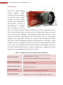
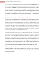
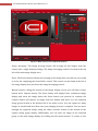
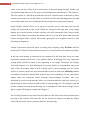
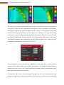
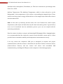
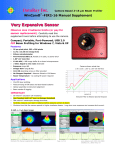
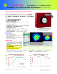
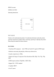
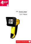
Jan. 27, 2012
Erfan Haghighi
ICI 7640 Infrared Camera
User Manual v 1.0
http://www.infraredcamerasinc.com/
ETH Zurich
CHN E 50.2, Universitatstrasse 16
Tel: 044 633 61 57
E-mail: [email protected]
2
ICI 7640 Infrared Camera: User Manual v 1.0
Table of Contents
Introduction………………………………………………….…………………………………………………………. 3
Quick User Guide for Camera Installation and Running ……………………………………………... 4
List of Tables
Table 1: Technical specifications of ICI 7640 Infrared Camera ………………………………….... 3
List of Figures
Figure 1: Main menu screen of IR Flash software ………………………………………………………. 5
Figure 2: The effect of NUC; (a) before Touch-Up and (b) after Touch-Up …………………… 7
Figure 3: Emissivity Correction dialog box ……………………………………………………………...… 7
3
ICI 7640 Infrared Camera: User Manual v 1.0
Introduction
ICI 7640 is a high resolution
thermal
imaging
camera
produced by Infrared Cameras
Cameras,
Inc. (ICI). This camera is a high
resolution and high sensitive
infrared camera equipped by a
microbolometer
icrobolometer detector. A
microbolometer
icrobolometer is a specific
type of bolometer used as a
detector in a thermal camera collecting the light in the 7.5 to 14 spectral band.
This spectral band provides a better penetration through smoke, smog, dust, water
vapor etc. because the wavelength is much longer than visible light in the 0.4 to 0.7 spectral band which in turn makes the ICI 7640 Infrared Camera an ideal thermal
imaging tool for applications including very sensitive temperature gradients.
gradients Unlike
other types of infrared detecting equipment, microbolometers do not require cooling
leading to low power consumption relative to cooled detector thermal imagers.
imagers ICI 7640
requires only 1 watt of power via USB connection. Despite such advantages, it should be
noted that microbolometer cannot be used for multispectral or high-speed
high
infrared
applications. Some highlights of the camera are as follow:
Table 1: Technical specifications of ICI 7640 Infrared Camera
- Detector Type: Microbolometer 640 480 UPFA VOX
Detector Specification
- Spectral Response: 8 12 - Resolution: 640 480 Pixels (Pixel Size: 25 25 )
- Thermal Time Constant: 14 Electronics and Data Rate
- Frame Rate: Up to 50 fps
- Thermal Sensitivity: 38 NETD (Measured Average)
Performance Specification
- Accuracy: 2 oC or 2 %
- Sensor Cooling: Not required
Camera Specification
- Typical Power: <1watts supplied through USB 2.0
- Weight: 127.6 without lens (148 with 25 lens)
Physical Specification
- Dimensions: 2.1" 3.2" 0.5 (53 81
13)
4
ICI 7640 Infrared Camera: User Manual v 1.0
ICI 7640 has been supplied with two software packages including ICI SDK version 3.7
which contains camera calibration files and camera driver files with which the camera
can be accessed and IR Flash as a professional thermal image analysis software package
allowing for radiometric image analysis of imagery captured by the IR camera. In
addition, there is one main connector and mating cable supplied as part of the Infrared
Cameras, Inc. camera system package. That cable is a standard USB 2.0 cable and must
be connected to the back plate of the camera unit before operation. In the following, a
quick guide for the installation and running the camera will be presented.
Quick User Guide for Camera Installation and Running
The data signal and communications is accomplished via the USB 2.0 port on the host
computer. There is one main connector and mating cable supplied as part of the
Infrared Cameras, Inc. camera system package. That cable is a standard USB 2.0 cable
and must be connected to the back plate of the camera unit before operation. It should
be noted that the camera drivers and IR Flash software have to be installed on the
computer, as well. When the installation is done, the program will be completely
installed and a note will appear telling you that the installation is complete. Hit any key
and you are ready to begin running the IR Flash program.
The main operating screen referred to as the Main Menu Screen is the first permanent
screen that appears when entering the program and all user activities will be originated
there (Figure 1). The Main Menu and Control Bar options are organized to break the
program into several logical functional groups. First note that before a complete menu
presentation is available, you must load an image into the software system or have the
camera running in live video mode. Once the camera is plugged into the USB port on the
computer this live video should be started. To load an image simply select the LOAD
option from the File Main Menu selection and make a file choice. The following is a
listing of some features found in IR Flash as you might find them on the main screen:
IR Colormap: The Color Palette section allows you to completely control the color
palette by which the current image is displayed, saved, and printed. The Color palette
selection control is a drop down menu located to the top and right of the image display
area as shown in Figure 1.
5
ICI 7640 Infrared Camera: User Manual v 1.0
Figure 1: Main menu screen of IR Flash software
Image Averaging: The Image Average button will average all the images from the
camera into a single displayed image. The Image Averaging control is located at the top
left of the main image display area.
Zoom: The Zoom function allows the zooming of the image data currently on screen and
is set by the employing the Zoom Slider control. This control can be found at the left of
the image display area just below the Image Averaging control.
Manual Capture: Along the bottom of the Image display screen you will find a Pause
button and a Capture button. The Pause button will simply Pause continuous image
display and show the image where the Pause button was pressed. In contrast, the
Capture button will capture an image from live display and move it to the captured
image group located at the bottom left of the main screen. You can capture as many
images as needed and save them once your imaging activity is complete. You can move
through the captured images using the slider controls located to the bottom of the
capture image group display. Additionally, you can move an image in the captured
group to the main image display by clicking the left mouse button. To return to live
6
ICI 7640 Infrared Camera: User Manual v 1.0
video, select the Live Video Icon at the bottom of the main image display. Finally, you
can export image data to two file types by selecting Export sub-menu via “File>Export”.
The first option is a MS Excel spread sheet file at a resolution that is allowed by Excel
and the second one is a CSV file which is an ASCII text file with the image placed in 480
rows of data with each row containing 640 data temperature data points (pixels).
Image Display Control: There are a group of controls used to fine-tune the way the
images are presented on the screen which are located at the right side of the image
display area. At the bottom of these controls is an AGC (Automatic Gain Control) radio
button. If this button is marked, the display will occur in the AGC mode otherwise, the
Center and Span Slider controls will activate giving the user complete control of how
this image is displayed.
Further information about IR image recording and analyzing using IR Flash could be
found in the “IR Flash Technical Manual version 1.0” documented on the software package.
In the case that camera is connected to the computer for the first time, there are some
important settings which have to be adjusted before IR imaging. The very important
setting which should be done at the beginning is the Image Touch-Up. The Imager
Touch-Up function is a Non-Uniformity Correction (NUC) to accommodate long term
drift of the electronics. What is NUC actually does is just averaging over the whole
surface to remove stripes we have basically due to the lens reflection. IR Flash provides
the ability to perform a manual NUC without the loss of sensitivity. To use this feature
simply make the sub-menu choice through “Camera>Image Touchup” and, once
indicated by an on-screen message, hold a very uniform and non-reflective surface (i.e.,
black body) in front of the lens and hit OK on that message box. The Image Touch-Up
will be complete as soon as the message box is disappeared. The effect of Image TouchUp on a typical IR imagery is depicted in Figure 2.
The Touch-Up function saves the Touch-Up data in a file and will be used at subsequent
boot-up of the camera. This data file can be deleted by simply selecting the Delete
Touch-Up sub-menu choice (Camera>Delete Touchup Data).
7
ICI 7640 Infrared Camera: User Manual v 1.0
(a)
(b)
Figure 2: The effect of NUC; (a) before Touch-Up and (b) after Touch-Up
The next step would be adjusting object parameters. Note that accuracy of temperature
conversion is typically more dependent on the physics of the scene than on the detailed
calibration/temperature model provided with the software. These physical properties
include emissivity and reflection of the target, the transmission in the intervening
atmosphere, and the background/foreground temperature within the scene and could
be adjusted making the sub-menu choice via “Temperatures>Emissivity Correction”.
The dialog box shown below allows the user the ability to offset some of this error by
defining these parameters as accurate as practical.
Figure 3: Emissivity Correction dialog box
Target Emissivity: You are provided the capability to select any value of surface optical
property of the target surface you consider appropriate to the analysis being performed.
Simply move the cursor to the Target Emissivity field and click the mouse button. Once
done enter the value from 1.0 to 100.0.
Transmission: This value is the percentage of energy loss due to the transmission of the
energy from the target surface to the camera. This loss can be a result of any intervening
8
ICI 7640 Infrared Camera: User Manual v 1.0
medium such as atmosphere, IR windows, etc. This loss is entered as a percentage value
from 1.0 to 100.0.
Ambient Temperature: The Ambient Temperature, which is often referred to as the
Background, is the temperature of the surfaces surrounding the imaged object. These
surfaces are those whose energy will hit the face of the imaged object and reflect from it
into the camera FOV.
Note: As the value of emissivity becomes lower, the error between the actual surface
temperature of the object and that shown by the camera becomes greater. A great deal of
error can be introduced into the calculation process if you are not careful with the
emissivity specification.
Now the camera is ready to a proper and meaningful IR imaging. Before imaging begins,
it is recommended that the camera be turned on and allowed to warm up for a short
period of time to maximize stability and temperature measurement accuracy.
If for any reason the computer’s USB port is disrupted at anytime and proper
communications with the camera is disturbed, hit the Reset Camera sub-menu choice
(Camera>Reset Camera) and the camera will reboot and reestablish USB
communication, providing the USB port on the computer is functioning properly.