1
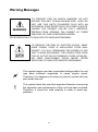
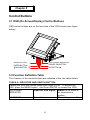
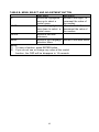
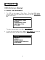
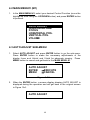
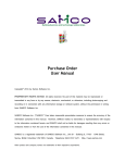
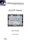
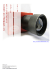
USER’S MANUAL POS 112 SERIES 12.1” TFT LCD Monitor 48200480 (December 2001 / Rev. 1.2) POS 112 User’s Manual This Manual was written for installation purposes. There are basic guidelines for front desk users operating this machine. The POS 112 User’s Manual is also available in the manufacturer website. The user can access this online in the internet. 1. Bookmarks The words and phrases showing on the left side of this screen are the bookmarks (subject of an operation) covering all topics in this manual. 2. Choosing a topic Select and find any desired topic by using the scroll bar next to the bookmarks. Click a bookmark to jump instantly to its topic that you wish to read. (If you wish, you can also increase the size of the bookmark area by dragging the dividing bar to the right.) 3. Magnifying the Page display Select and use the Zoom tools to magnify or reduce the page display. 4. Finding a term Click the Find button if you want to search for a particular term. (However, using the bookmarks is usually quicker.) ® Complete online documentation for Acrobat Reader is located in the Help ® directory for Acrobat Reader. To view *.pdf files, click on . i COPYRIGHT All rights reserved. The information contained in this manual (guide) has been validated and reviewed for accuracy. No patent liability is assumed with respect to the use of the information contained herein. While every precaution has been taken in the preparation of this guide, the Manufacturer assumes no responsibility for errors or omissions. No part of this publication may be reproduced, stored in a retrieval system, or transmitted in any form or by any means, electronic, mechanical, photocopying, recording, or otherwise, without the prior written permission of Manufacturer. TRADEMARK ® ® ® Intel , Pentium and MMX are registered trademarks of Intel Corporation. ® ® Microsoft and Windows are registered trademarks of Microsoft Corporation. EloTouch is the registered trademark of Elo TouchSystems ® . General Notice: Other products and company names used herein are for identification purposes only and may be trademarks of their respective companies. POS 112 are registered trademarks of Manufacturer. NOTICE The contents of this manual are subject to change without notice. Copyright by Manufacturer. (December 2001, Rev. 1.2) Part no. 48200480 ii FCC COMPLIANCE STATEMENT FOR AMERICAN USERS This equipment has been tested and found to comply with the limits for a Class A digital device, pursuant to Part 15 of the FCC Rules. These limits are designed to provide reasonable protection against harmful interference when the equipment is operated in a commercial environment. This equipment generates, uses, and can radiate radio frequency energy and, if not installed and used in accordance with the instruction manual, may cause harmful interference to radio communications. Operation of this equipment in a residential area is likely to cause harmful interference, in which case the user will be required to correct the interference at his own expense. WARNING The connection of a non-shielded interface cable to this product will invalidate the FCC Verification of this device and may cause interference levels which exceed the limits established by the FCC for this equipment. You are cautioned that changes or modifications not expressly approved by the party responsible for compliance could void your authority to operate the equipment. If necessary, the user should contact the dealer or an experienced radio/television technician for additional suggestions. The user may find the following booklet, prepared by the Federal Communications Commission, helpful: “ How to Identify and Resolve Radio-TV Interference Problems.“ This booklet is available from the U.S. Government Printing Office, Washington, D.C., 20402, Stock No. 004-000-00345-4. CANADIAN DEPARTMENT OF COMMUNICATIONS COMPLIANCE STATEMENT FOR CANADIAN USERS DOC: This Class A digital apparatus meets all requirements of the Canadian Interference-Causing Equipment Regulations. iii Warning Messages TO PREVENT FIRE OR SHOCK HAZARDS, DO NOT EXPOSE THIS UNIT TO RAIN OR MOISTURE. ALSO, DO NOT USE THIS UNIT'S POLARIZED PLUG WITH AN EXTENSION CORD RECEPTACLE OR OTHER OUTLETS UNLESS THE PRONGS CAN BE FULLY INSERTED. WARNING REFRAIN FROM OPENING THE CABINET AS THERE ARE HIGH VOLTAGE COMPONENTS INSIDE. REFER SERVICING TO QUALIFIED TECHNICIAN PERSONNEL. TO REDUCE THE RISK OF ELECTRIC SHOCK, MAKE SURE POWER CORD IS UNPLUGGED FROM WALL SOCKET. TO FULLY DISENGAGE THE POWER TO THE UNIT, PLEASE DISCONNECT THE POWER CORD FROM THE AC OUTLET.DO NOT REMOVE COVER (OR BACK). NO USER SERVICEABLE PARTS INSIDE. REFER SERVICING TO QUALIFIED SERVICE PERSONNEL. ~ ! This symbol warns user that uninsulated voltage within the unit may have sufficient magnitude to cause electric shock. Therefore, it is dangerous to make any kind of contact with any part inside this unit. This symbol alerts the user that important literature concerning the operation and maintenance of this unit has been included. Therefore, it should be read carefully in order to avoid any problems. vi Contents Chapter 1 1.1 1.2 1.3 1.4 1.5 Chapter 2 2.1 2.2 2.3 2.4 2.5 2.6 2.7 2.8 1 2 3 4 4 Getting Started Setup. . . . . . . . . . . . . . . . . . . . . . . . . . . . . . . . . . . . . . . . . . . . . 5 Precautions for Setup. . . . . . . . . . . . . . . . . . . . . . . . . . . . . . . . 5 Unpacking POS 112. . . . . . . . . . . . . . . . . . . . . . . . . . . . . . . . . 7 Installing the MCR Module (option) . . . . . . . . . . . . . . . . . . . . . 9 Quick Start. . . . . . . . . . . . . . . . . . . . . . . . . . . . . . . . . . . . . . . . 10 Adjustable View Angle. . . . . . . . . . . . . . . . . . . . . . . . . . . . . . . . 13 Mounting the LCD monitor. . . . . . . . . . . . . . . . . . . . . . . . . . . . . 13 Installation the Customer Pole Display Module (option) … … … … . 1 4 Chapter 3 3.1 3.2 Introduction Introduction. . . . . . . . . . . . . . . . . . . . . . . . . . . . . . . . . . . . . . . . Hardware Outlook – Front View. . . . . . . . . . . . . . . . . . . . . . . . Hardware Outlook – Rear View. . . . . . . . . . . . . . . . . . . . . . . . . Hardware Outlook – Option Module View. . . . . . . . . . . . . . . . . Handling Guidelines. . . . . . . . . . . . . . . . . . . . . . . . . . . . . . . . . Control Buttons OSD (On-Screen Display) Control Buttons. . . . . . . . . . . . . . . . 15 Function Definition Table. . . . . . . . . . . . . . . . . . . . . . . . . . . . . . 15 Chapter 4 OSD 4.1 4.2 4.3 4.4 4.5 4.6 4.7 4.8 4.9 4.10 4.11 4.12 4.13 4.14 4.15 About the Main menus. . . . . . . . . . . . . . . . . . . . . . . . . . . . . . . . 17 Main Menu #1 (M1). . . . . . . . . . . . . . . . . . . .. . . . . . . . . . . . . . . 18 Auto Adjust Sub-menu . .. . . . . . . . . . . . . . . .. . . . .. . . . . . . . . . 18 Horizontal Size . . . . . . . . . . . . . . . . . . . . . . . . . . . . . . . . . . . . 19 Focus Sub-menu. . . . . . . . . . . . . . . . . . . . . . . . . . . . . . . . . . . . 20 Horizontal Pos.Sub-menu. . . . . . . . . . . . . . . . . . . . . . . . . . . . . . 21 Vertical Pos. Sub-menu. . . . . . . . . . . . . . . . . . . . . .. . . . . . . . . . 22 Volume Sub-menu. . . . . . . . . . . . . . . . . . . . . . . . . . . . . . . . . . . 23 Main Menu #2 (M2) . . .. . . . . . . . . . . . . . . . . . . . . . . . . . . . . . 24 Color Sub-menu . .. .. . . . . . . . . . . . . . . . . . . . . . . . . . . . . . 25 Recall Sub-menu . . .. . . . . . . . . . . . . . . . . . . . . . . . . . . . . . . . . 26 Video Sub-menu . . .. . . . . . . . . . . . . . . . . . . . . . . . . . . . . . . . 27 Brightness Sub-menu . . . . . . .. . . . . . . . . . . . . . . . . . . . . . . . 28 Language Sub-menu . . .. . . . . . . . . . . . . . . . . . . . . . . . . . . 29 DOS Mode Sub-menu . . .. . . . . .. . . . . . . . . . . . . . . . . . . . . . 30 vi Chapter 5 Proper Use 5.1 Safety Precautions. . . . . . . . . . . . . . . . . . . . . . . . . . . . . . . . . . . 5.2 Maintenance Conditions. . . . . . . . . . . . . . . . . . . . . . . . . . . . . . . 5.3 Healthy Tips Considerations. . . . . . . . . . . . . . . . . . . . . . . . . . . . 5.4 Ergonomics Concern . . . . . . . . . . . . . . . . . . . . . . . . . . . . . . . . . 31 32 33 34 Chapter 6 Specification 6.1 Monitor Specifications. . . . . . . . . . . . . . . . . . . . . . . . . . . . . . . . . 35 Chapter 7 Troubleshooting 7.1 Troubleshooting . . . . . . . . . . . . . . . . . . . . . . . . . . . . . . . . . . . . 36 Appendix A Glossary . . . . . . . . . . . . . . . . . . . . . . . . . . . . . 38 Appendix B LCD Panel Display . . . . . . . . . . . . . . . . . . 40 Appendix C Touchscreen Technology . . . . . . . . . . . 43 vi Chapter 1 Introduction 1.1 Introduction The POS 112 touchscreen monitor offers the fabulous image quality in a 12.1” monitor screen with the most advanced touchscreen from the world’s leading provider of touch technology. The POS 112 touchscreen monitor system comes with a card reader (MCR) for retail application (MCR is an abbreviation of Magnetic Card Reader). Th e POS 112 touchscreen monitor is well-suited for applications utilizing touchscreen interface in industries covering retail Point-of-Sale, hospitality, interactive kiosks, information, medical, and other industrial environment. Point-of-Sale is widely used in environments covering hospitals, schools, tourist destination and any retail locations. The POS 112 monitor has a viewing angle from 0° to 60°, that is best suited for front desk operators. Setup is fairly easy and automatic for the image size and position. The POS 112 had no pixel defects, but there were noticeable dark areas along the bottom edge and upper-right corner – does not affect the viewing angle in most LCD Display Panel. The automatic settings required some small adjustments to eliminate jitter. Color performance is smoother in the dark shades, making this panel better at displaying images with shadows. Text and video image quality are good. It has an appealing offer for retail locations that allows point-to-point services. Our standard POS 112 touchscreen monitor utilizes the resistive touch technology that allows gloved hand interface, as well as operation in an environment where dust and moisture are present. Therefore, this technology is ideally suited for restaurant and Point-Of-Sale applications. The POS 112 touchscreen monitor has it’s purpose of combining technology with meeting demands of online user’s in different corner of retail business transaction. Today, the touchscreen has been transformed the early complication in PC into a more user-friendly environment by replacing the robust computer keyboard and mouse. With the touchscreen technology, people with little or no computer experience can instantly work with complex software programs, without even being aware they 're doing it. And computers can go to work in places where a keyboard or mouse would too cumbersome, fragile, or impractical. 1 The POS 112 touchscreen monitor is actually the world’s most economical PC Retail System that is equipped with (1)Touchscreen and (2)Magnetic Card Reader. MCR is sometimes known as MSR that stands for Magnetic Stripe Reader, and can be refer to as smart card reader that is best suited for Country club membership. Easily and ready for on-site maintenance with an external connection of keyboard and a second VGA monitor, without moving the system out of it’s location. Note: For more info about Elo Touchscreen, please refer to Elo website, http://www.elotouch.com/. The MCR (Magnetic Card Reader) unit and Customer Pole Display (VFD) are tested and supply to the customer at your request. They are removed during transportation and can be connected by the user following the direction as indicated in Chapter 2 Setup, section 2.4. Installing a MCR Module, section 2.8 installing a Customer Pole Display Module. 1.2 Hardware Outlook – Front View The Illustration shown below defines the part names of this product. Touch Screen LCD Monitor Magnetic Card Reader 1 Watt Speaker 1Watt Speaker Menu Button Power LED Enter Button Power Button Adjust Down Button Adjust Up Button Front View 2 1.3 Hardware Outlook – Rear View Looking at the Base unit of the POS 112 LCD Monitor, you can find the following connectors available for connection to your PC system. VGA SERIAL-A SERIAL-B K/B IN K/B OUT AUDIO-IN Rear View Connectors Assignment Name of Connector 1. VGA For connection to External VGA Monitor 2. SERIAL-A Touchscreen 3. SERIAL-B 4. K/B IN Magnetic Card Reader (RS-232C type interface) Magnetic Card Reader (PS/2 type interface) 5. K/B OUT External Keyboard 5. AUDIO-IN For Speaker(s) use only Note: When connecting to a PC system, attach the VGA cable to VGA connector, then connect SERIAL-A to either one of COM1~COM4 of the PC system. To connect to COM5/6, please check the system BIOS before connection. 3 1.4 Hardware Outlook – Option Module View In some cases, user can purchase our barebone hardware system with the exclusion MCR module. In case of future requirement, the MCR and Customer Pole Display can be sold as an option. And you are advised not to do the installation alone with proper technical training. Contact your dealer for authorized technician support. MCR Module Customer Pole Display 1.5 Handling Guidelines Warning and Precaution The notes on the precautions in this manual are identified by the level of their importance. Definitions are listed below. F WARNING This note provides the information that must be observed to prevent harm to the user (though such harm is not life-threatening). ê CAUTION This note provides information that must be observed to prevent damage to the equipment or loss of data. ! NOTE This note provides an important information and useful tips on handling the equipment. 4 Chapter 2 Getting Started 2.1 Setup This chapter explains on how to set up your hardware. For adjustment of display, please see the next chapter for On-Screen Display (OSD). 2.2 Precautions for Setup This section describes the important steps when setting up the POS 112. In addition to the above, observation on the warning instructions and precautions are necessary at each work stage. These instructions are given with an explanation. ê CAUTION 1. Be sure to turn off the power of all equipment including the POS 112 and it’s peripherals before setup. Otherwise, the peripherals units may be damaged during setup. 2. Before setup, be sure to discharge the static electricity on your body. Defects may result on the product if you do not allow static electricity to discharge. Find and touch your body (hand) to a grounded metal surface to allow static electricity to discharge. 3. Do not touch the connectors with your fingers, to prevent the dirt residue from causing malfunction. 5 F WARNING 1. Do not attempt to repair this product by yourself. n Improper repair can be dangerous. 2. Do not disassemble or modify this product. n Tampering with this product may result in injury, fire, or electric shock. 3. Do not insert or disconnect the power cord plug with wet hands. n Doing this may result in severe shock. 4. Do not allow foreign objects to fall into this product. n Penetration of foreign objects may lead to fire or shock. 5. Do not place multiple loads on the power outlet (wall outlet). n Overloading the outlet may lead to fire. 6. Do not spills water or other liquid subject into this product. It happens, turn off the power switch of the System Unit and unplug the power cable immediately. n Continuing usage may lead to fire or shock. 7. Always supply power directly from a standard domestic power outlet. 8. Handle the power cable with care without scratching the outer protective rubber insulation. Do not place the cable under a heavy object. Neither the Manufacturer nor his Affiliates shall be liable to the purchaser of this product for damages, losses, costs, or expenses incurred as a result of accident, misuse, abuse of this product, unauthorized modifications, repairs, or alterations of this product or failure without strictly complying with Manufacturer's operating and maintenance instructions. 6 2.3 Unpacking POS 112 1. Open the transport carton box and take out your POS 112 monitor unit. Check if the unit is properly secure in the plastic bag and clutch with two PE foam subjects . 2. Check the contents of the carton box: l l l l l l l 3. POS 112 – 12.1” TFT LCD Monitor unit Power Cord x1 VGA Cable x1 RS232 Serial Cable x1 (excluded when ordering without touch panel ) User’s Manual CD Driver Bank Audio cable The carton box should contain the following: ← Installation Guide ↑ POS 112 Hardware system → CD Driver Bank ↓Cables VGA Cable Power Cord RS232 Serial cable x 1 Audio in Cable 7 4. Check the glass surface of the LCD panel display on the POS 112 is sealed with a protective film. Note : Remember to save your original box and packing material to transport or ship the monitor. Standard accessory bag Name of Accessory 1. Installation Guide Q’ty Length 1 2. CD Driver Bank 1 3. Power cord 1 4. VGA cable 1 *5. RS232C Serial cable 1 From 180 cm 3-pin Outlet Connector cable 90 cm 15-pin D-sub connector cable 90 cm To 3-pin Inlet Connector 15-pin D-sub connector 9-pin D-sub 9-pin D-sub connector. connector Flat cable 6. Audio cable 1 90 cm 3C male plug cable 3C male plug connector *excluded serial cable when ordering without touch panel Option 1: Keyboard-in MCR accessory kit Name of Accessory 1. Magnetic Card Reader 2. PS/2 cable Q’ty Length 1 -- 1 90 cm From To 3-Tracks/PS/2 type 6-pin Mini-Din 6-pin Mini- Din connector. connector cable Note : The MCR kit can be order separately and installed at the Dealer site. Option 2: Serial-in MCR accessory kit Name of Accessory 1. Magnetic Card Reader 2. RS232C Serial cable Q’ty Length From 1 -3-Tracks/D-Sub type To 1 90 cm 9-pin D-sub 9-pin D-sub connector. connector Flat cable Note : The MCR kit can be order separately and installed at the Dealer site. Option 3: Customer Pole Display accessory kit Name of Accessory 5. Q’ty Length 1. Customer Pole Display 1 2. cable 1 From To -50 cm RJ-45(10-P) Flat Cable 9-pin D-sub connector Now you are ready to install your LCD monitor to the PC system. 8 2.4 Installing the MCR Module (option) 2.4.1 Installing the MCR Module The LCD module and touchscreen are equipped with an interface for a connection to a Magnetic Card Reader (MCR). Mount the MCR module by following the procedure described below. 1. Open the MCR module on the package and check it. MCR Module (option) 2. Connect the MCR module to the right side of LCD module and lock it using two screws. Lock screws 2.4.2 Removing an MCR module: To remove the MCR module, reverse the installation steps. ! NOTE: When you remove the screws and then want to fix them again, first turn off the power. 9 2.5 Quick Start To attach your POS112 LCD monitor to your PC system, follow these instructions: 1. Turn off the power of your computer. 2. Choose the appropriate type of VGA cable for the desired PC system for the PC :Connect the 15-pin high density D-SUB connector of the appropriate signal cable to the connector of the display card in your system (Figure 2.5A). Tighten all screws. 3. Attach and connect the 15-pin mini D-SUB of the VGA cable and the AC Adapter cable. NOTE: Incorrect cable connections may result in irregular operation, damage the LCD module and shorten the module’s life. 4. Connect one end of the power cord to the AC Adapter and the other end to the power outlet (Figure 2.5B). Figure 2.5A 10 5. Turn on the power of the monitor (Figure 2.5B). and the computer. Power Button Figure 2.5B 6. Refer to your CD Driver bank for Touch installation; look for the EloTouch Driver and install this at the System under Control Panel Icon (in Add new hardware). You may also refer to the Elo website --http://www.elotouch.com/. NOTE: If you have any problems, please refer to the Troubleshooting section of this User’s Manual. 11 ê CAUTION 1. Be sure to check that your power adapter meets the relevant safety standards and includes a PE terminal (power-system ground terminal). 2. Be sure to check that this equipment is set on a firm flat horizontal surface. Otherwise, the product may break or cause injury when it falls. 3. Be sure to check that all the front and back covers is secure properly after installing the peripheral options. 4. Do not attempt to use the product in locations that are subject to high humidity or dust levels. Excessive humidity and dust can cause this product to damage, to cause fire or shock. 5. Do not place heavy objects on top of this product. The product may collapse or slip to the side and fall, causing breakage and possible injury. 6. Do not drop, bump or subject this product to strong vibration or impact. 7. For safety reasons, please unplug this product when you leave it unattended or unused for an extended period of time. 12 2.6 Adjustable View Angle Grasp both sides of the monitor screen with your hands and adjust it by tilting it upwards as desired (See Figure Below). Your hands on both edges Pulling it upwards Note: There is a Tilt-raising mechanism that locks on as you release the monitor screen downwards after you have stop raising it upwards. 2.7 Mounting the LCD monitor The monitor can be mounted either on top of the working table or atop a cash drawer in retail POS application depending on it’s purpose of use. Cash Drawer Flat Working Table 1. 2. 3. Be sure that the LCD monitor is placed on a flat table or a cash drawer (use in retail application). The edges of the monitor must not exceed the surface of sitting. This is to prevent from falling off and causing damage to the monitor. Check all cables are connected properly before use. Now you have the monitor ready for use. 13 2.8 Installation Customer Pole Display Module (option) Following procedure explain how to install Customer Pole display to POS 112 LCD monitor. 1. (1a.)Remove Pole Display cover from POS 112 system unit by fingers. (1b.) Set Pole Display Stud onto POS112 base by using two screws. Fig. 1a. 2. Fig. 1b. (2a.)Unscrew two adjustment nubs of the Pole Display module. (2b Install the flat cable with RJ-45 end across the Pole Stud of POS112 system unit and the Pole Display Tube. You can use two tubes or just one of them according to the height of your desire. Fig. 2a. 3. Fig. 2b (3a.)Connect the flat cable RJ-45 end to the Pole Display module. (3b) Set the Pole Display module and the tube(s) onto the Pole stud of POS112 system unit. (3c.) Connect the Pole Display DB9M cable connector to COM2 of POS112 system. Fig. 3a. Fig. 3b. 3c. 14 Chapter 3 Control Buttons 3.1 OSD (On-ScreenDisplay) Control Buttons OSD control buttons are on the front side of the LCD monitor (see figure below). MENU BUTTON ENTER BUTTON DOWN BUTTON ▼ 6 LED POWER INDICATOR POWER ON BUTTON UP BUTTON ▲ 3.2 Function Definition Table The Function of the control buttons are indicated in the two tables below TABLE A: INDICATOR AND SWITCH BUTTON: Viewing the front side control panel from Right to Left. To access the OSD, press the MENU button. And Press ENTER to exceed the OSD. LED POWER Green for VGA signal . Amber for no video or INDICATOR no connection to system. POWER-ON To turn the power on. To turn the power off 15 TABLE B: MENU SELECT AND ADJUSTMENT BUTTON Main Menu Sub-Menu UP Moves the highlighted Moves to the Right , to area up to select a increment the value of control menu. the number. DOWN Moves the highlighted Moves to the Left, to area down to select a decrement the value of control menu.. the number. ENTER Moves to the next sub-menu MENU Moves to the Language Moves to the Main Menu selection Menu NOTE: (1) To save a function, press ENTER button. (2) If you do not use or change any value of the control function, the OSD will be disappear in 16 seconds. 16 Chapter 4 OSD (On-Screen Display) 4.1 ABOUT THE MAIN MENUs 1. The OSD has two pages of Main Menu. Press the MENU button once to bring up the first page menu and enter to M1 (MAIN MENU #1)as shown below. AUTO ADJUST HORIZONTAL SIZE FOCUS HORIZONTAL POS. VERTICAL POS. VOLUME The above screen display is the M1 or MAIN MENU #1. 2. To enter the second page menu, M2 or MAIN MENU #2, press the Menu button twice (see the screen display diagram below). COLOR RECALL VIDEO BRIGHTNESS LANGUAGE: ENGLISH DOS MODE 17 4.2 MAIN MENU#1 (M1) 1. In the MAIN MENU #1, select your desired Control Function (move the highlighted area using the UP/DOWN button) and press ENTER button to proceed. AUTO ADJUST HORIZONTAL SIZE FOCUS HORIZONTAL POS. VERTICAL POS. VOLUME 4.3 AUTO ADJUST SUB-MENU 1. Select AUTO ADJUST and press ENTER button to go the sub-menu. Press ENTER button to make the necessary adjustments of the display focus and H-total and V-total for adequate viewing. Press MENU button to cancel and get back to the MAIN MENU #1. AUTO ADJUST ENTER EXECUTE MENU CANCEL Figure 1-AA 2. When the ENTER button, a screen display showing AUTO ADJUST is displayed during the operation and will get back to the original screen in Figure 1AA. AUTO ADJUST 18 3. When the operation is completed, another screen display showing COMPLETE will be shown for 3 seconds and disappear. COMPLETE 4.4 HORIZONTAL SIZE SUB-MENU 1. In the MAIN MENU #1, you may choose to select the next function – HORIZONTAL SIZE, by moving the UP/DOWN buttons. and press ENTER button to proceed. AUTO ADJUST HORIZONTAL SIZE FOCUS HORIZONTAL POS. VERTICAL POS. VOLUME 2. In the sub-menu of the HORIZONTAL SIZE function, make the necessary adjustment by pressing the UP/DOWN button to decrease/increase the size; DOWN button for NARROW mode and UP button for WIDE mode respectively. HORIZONTAL SIZE NARROW 34 WIDE After making the change, press the ENTER button to go back the MAIN MENU#1. 19 4.5 FOCUS SUB-MENU 1. In the MAIN MENU #1, you may choose to select another function – FOCUS, by moving the UP/DOWN buttons and press ENTER button to proceed. AUTO ADJUST HORIZONTAL SIZE FOCUS HORIZONTAL POS. VERTICAL POS. VOLUME 2. In the sub-menu of the FOCUS function, make the necessary adjustment by pressing the UP/DOWN button to decrease/increase the focus of the image. FOCUS ÕÕÕÕÕÕÕÕÕÕÕÕÕÕÕÕ, (6) NOTE: The focus is made fine to improves the image stability. 3. After making the change, press the ENTER button to go back the MAIN MENU#1. 20 4.6 HORIZONTAL POSITION SUB-MENU 1. In the MAIN MENU#1, you may choose to select the next function – HORIZONTAL POS., by moving the UP/DOWN buttons. And press ENTER button to proceed. AUTO ADJUST HORIZONTAL SIZE FOCUS HORIZONTAL POS. VERTICAL POS. VOLUME 2. In the sub-menu of the HORIZONTAL POS. function, make the necessary adjustment by pressing the UP/DOWN button to SHIFT the screen display from RIGHT to LEFT for better viewing at the centerpoint of your vision. HORIZONTAL POS. LEFT 34 RIGHT NOTE: The HORIZONTAL POS. controls Horizontal Image Position within the display area of the LCD. After making the change, press the ENTER button to go back the MAIN MENU#1. 21 4.7 VERTICAL POSITION SUB-MENU 1. In the MAIN MENU#1, you may choose to select the next function – VERTICAL POS., by moving the UP/DOWN buttons. And press ENTER button to proceed. AUTO ADJUST HORIZONTAL SIZE FOCUS HORIZONTAL POS. VERTICAL POS. VOLUME 2. In the sub-menu of the VERTICAL POS. function, make the necessary adjustment by pressing the UP/DOWN button to SHIFT the screen display UP and DOWN LEFT for better viewing at the centerpoint of your vision. VERT. POSITION DOWN Ÿ UP NOTE: The VERTICAL POS. controls Vertical Image Position within the display area of the LCD. 3. After making the change, press the ENTER button to go back the MAIN MENU#1. 22 4.8 VOLUME SUB-MENU 1. In the MAIN MENU#1, you may choose to select the next function – VOLUME, by moving the UP/DOWN buttons. And press ENTER button to proceed. AUTO ADJUST HORIZONTAL SIZE FOCUS HORIZONTAL POS. VERTICAL POS. VOLUME 2. In the sub-menu of the VOLUME function, make the necessary adjustment by pressing the UP/DOWN button to increase or decrease the sound of the volume. VOLUME ( 31) 3. After making the adjustment, press the ENTER button to go back the MAIN MENU#1. Depress ENTER button to save the current changes and move out of the OSD Menu. i Information While the display is capable of other resolutions (as with all flat panel displays), it is a fixed matrix of pixels and best used at its native resolution – 800 x 600. For further information, please refer to your display card or system manual. 23 4.9 MAIN MENU #2 (M2) 1. Press the MENU button twice to proceed to the second page menu M2. Below is the MAIN MENU #2 that you selected. Select COLOR and press ENTER button. COLOR RECALL VIDEO BRIGHTNESS LANGUAGE: ENGLISH DOS MODE 4.10 COLOR SUB-MENU 1. When COLOR menu is selected, a screen display showing – COLOR AUTOCONTRAST DEFAULT USER R ŸŸŸŸŸŸŸŸŸŸŸŸŸŸ½ USER G ŸŸŸŸŸŸŸŸŸŸŸŸŸŸŸ USER B ŸŸŸŸŸŸŸŸŸŸŸŸŸŸŸ, 2. When you choose AUTOCONTRAST by depressing the ENTER button, a screen display will be shown to make the changes. AUTOCONTRAST ENTER EXECUTE MENU CANCEL 24 3. Select ENTER for AUTOCONTRAST execution on the R-G-B color. Otherwise, select MENU to cancel and default execution, and get back to the previous screen display as shown in Figure 2-AC. COLOR AUTOCONTRAST DEFAULT USER R ŸŸŸŸŸŸŸŸŸŸŸŸŸŸŸŸŸ, USER G ŸŸŸŸŸŸŸŸŸŸŸŸŸŸŸŸŸŸŸ USER B ŸŸŸŸŸŸŸŸŸŸŸŸŸŸŸŸŸŸ, Figure 2-AC 4. In the COLOR sub-menu, you may also choose to make an individual separate adjustment for R-G-B by moving the UP/DOWN button, to any USER R, USER -G or USER B like the screen display as shown in the next page – COLOR AUTO CONTRAST DEFAULT USER R ŸŸŸŸŸŸŸŸŸŸŸŸŸŸŸŸŸŸŸŸ USER G ŸŸŸŸŸŸŸŸŸŸŸŸŸŸŸŸŸŸŸŸ, USER B ŸŸŸŸŸŸŸŸŸŸŸŸŸŸŸŸŸŸŸŸŸŸŸ 25 5. Same thing is done for USER G (Green color) and USER B (Blue color). Adjust to the desired COLOR and press ENTER button. Move the cursor to your right using UP button to Increments, and DOWN button to your left for decrements Notes for the following functions – AUTOCONTRAST: Adjust the image displayed for non-standard video inputs. CONTRAST: Adjusts the image brightness in relation to the background. R,G,B: Increases or decreases Red, Green or Blue color depending upon which is selected. The change in color will appear on screen and the direction (increase or decrease) will be shown by the bars. 6. To quit or get back to the MAIN MENU #2, move the highlighted area to DEFAULT, and press ENTER button. COLOR AUTO CONTRAST DEFAULT USER R ŸŸŸŸŸŸŸŸŸŸŸŸŸŸŸŸŸŸ, USER G ŸŸŸŸŸŸŸŸŸŸŸŸŸŸŸŸŸŸ, USER B ŸŸŸŸŸŸŸŸŸŸŸŸŸŸŸŸŸŸ 7. Shown below is the screen display of the MAIN MENU #2: COLOR RECALL VIDEO BRIGHTNESS LANGUAGE: ENGLISH DOS MODE 26 4.11 RECALL SUB-MENU 1. Move the highlighted area down to select RECALL function, press ENTER button to proceed to the next second sub-menu. COLOR RECALL VIDEO BRIGHTNESS LANGUAGE: ENGLISH DOS MODE 2. In the sub-menu of RECALL function, press ENTER button to EXECUTE and get back to the previous settings and setup before making any changes. RECALL ENTER MENU EXECUTE CANCEL Press MENU button to CANCEL the RECALL function, and get back the MAIN MENU#2. 4.12 VIDEO SUB-MENU 1. Move the highlighted area down to select VIDEO MODE function, press ENTER button to proceed to the next second sub-menu. COLOR RECALL VIDEO BRIGHTNESS LANGUAGE: ENGLISH DOS MODE 27 2. In the sub-menu of the VIDEO function, press ENTER button to check the display setting information. VERT. SYNC 56.4HZ HOR. SYNC 35.2KHZ VERT. POLARITY P HOR. POLARITY P RESOLUTION 800X600 4.Press MENU button to go back to MAIN MENU #2 screen display. 4.13 BRIGHTNESS SUB-MENU 1. Move the highlighted area down to next function to select BRIGHTNESS function, press ENTER button to proceed to the next second sub-menu. COLOR RECALL VIDEO BRIGHTNESS LANGUAGE: ENGLISH DOS MODE 28 2. In the sub-menu of the BRIGHTNESS function, move the cursor to your right using UP button to increments, and DOWN button to your left for decrements. BRIGHTNESS ½½½½½½½½½½½½½½½½ ( 18 ) Press ENTER button once to save the current changes and adjustment. Press MENU button for the second time, and leave the MAIN MENU #2. NOTE: BRIGHTNESS – is set to adjust the overall image and background screen brightness. 4.14 LANGUAGE SUB-MENU 1. Move the highlighted area down to select LANGUAGE function, press ENTER button to proceed to the next second sub-menu. COLOR RECALL VIDEO BRIGHTNESS LANGUAGE: ENGLISH DOS MODE 2. Using UP/ DOWN button to select your desired language. Press ENTER button to save the change, and leave the MAIN MENU #2. 29 4.15 DOS MODE SUB-MENU 1. You may choose to select and to move the highlighted area down to select DOS MODE function, press ENTER button to proceed to the next second sub-menu. COLOR RECALL VIDEO BRIGHTNESS LANGUAGE: ENGLISH DOS MODE 3. The sub-menu of the DOS MODE function can be executed in VGA resolution 640*400 and 720*400. move the cursor using UP button to select GRAPHIC mode or DOWN button for TEXT mode. DOS MODE GRAPHIC TEXT Press the enter button to go save your selection. Press MENU button for the second time, and go back to MAIN MENU #2. 30 Chapter 5 Proper Use 5.1 Safety Precautions Safety precaution must be strictly taken into account before doing any repair or maintenance. To ensure threaten and hazard to human body, be sure to contact your supplier for authorized technician support. WARNING n n n n n n n n FOR OPTIMUM PERFORMANCE, PLEASE NOTE THE FOLLOWING INSTRUCTION AND SETUP NOTES BEFORE USING THE POS 112 LCD COLOR MONITOR. NEVER OPEN THE COVER OF YOUR MONITOR BY ALL MEANS. There are no user serviceable parts inside the monitor. Opening the covers may expose you to dangerous shock hazards or other risks. Contact your supplier for authorized servicing technician. Do not place the monitor on a slope or any unstable surface or cart, the monitor may fall to cause serious damage. Do not spill any form of liquids on the surface of the monitor or it’s cabinet. Prevent use of monitor near the water. Do not insert foreign objects into the cabinet slots, to prevent from touching dangerous voltage pins, which can be harmful to the human body with electric shock. When this happens, you monitor is subjected to equipment failure. Do not place any heavy objects on the power cord. Damage to the cord may cause shock or fire. Do not block the ventilated openings in order to allow adequate ventilation for heat dissipation by the LCD monitor. Do not put anything on top of monitor. Do not place the LCD monitor near a radiator or other heat sources. When operating the POS 112 LCD monitor with its AC100~240V universal power supply, use a power supply cord that matches the power supply voltage of the AC power outlet being used. The power supply cord must comply with the safety standards of your country. In UK, use a BS-approved power cord with molded plug having a black (SA) fuse installed for use with this monitor. If a power cord is not supplied with this monitor, please contact your supplier. 31 n n n n Use the supplier’s AC Power Adapter. Do not place any objects on the connecting pins of the Adapter. Do not use the Adapter outdoors. The LCD monitor should be installed close to a power outlet which is easily accessible. The power cable connector is the primary means of detaching the system from the power supply. Handle with care when transporting. Save the packaging for transporting. To dispose the LCD monitor, please check and follow the bylaws of your local municipality. Please take note that the LCD monitor has a fluorescent tube inside that contains mercury. 5.2 Maintenance Conditions Unplug your monitor immediately from the wall outlet when you encountered the following conditions – n n n n n The power supply cord or plug is damaged. The LCD monitor has been exposed to rain or water. The LCD monitor has been dropped or the cabinet is damaged. The LCD monitor does not operate normally by following operating instructions. The ventilated holes of the LCD monitor has been subjected to the entry of fallen foreign objects or spilled liquid. NOTE: Refer the servicing to an authorized technician. 32 5.3 Healthy Tips Considerations ADEQUATE SITTING POSTURE, PROPER ADJUSTMENT AND CORRECT PLACEMENT OF THE MONITOR CAN REDUCE EYE, SHOULDER AND NECK FATIGUE. CHECK THE FOLLOWING STEPS WHEN YOU POSITION THE MONITOR: n For optimum performance, allow the LCD monitor to warm-up for 20 minutes. n Adjust the monitor height so that your eyes should look slightly downward when viewing the middle of the screen. (the top of the screen is slightly below eye Good posture level). Straight posture n Position your monitor no closer than 16 inches and no further away than 28 inches from your eyes. The optimal distance is 21 inches. n Rest your eyes periodically by focusing on an object at least 20 feet away. Blink often. n Position the monitor at a 90°angle to windows and other light sources to minimize glare and reflections. Adjust the monitor tilt so that ceiling lights do not reflect on your screen. n If reflected light makes it hard for you to see your screen, use an anti-glare filter. n Clean the LCD monitor surface with a lint-free, non-abrasive cloth. Avoid using any cleaning solution or glass cleaner! n Adjust the monitor’s brightness and contrast controls to enhance readability. n Use a document holder placed close to the screen. n Position whatever you are looking at most of the time (the screen or reference material) directly in front of you to minimize turning your head while you are typing. n Avoid displaying fixed patterns on the monitor for long periods of time to avoid image persistence (after-image effects). n Get regular eye checkups. 33 5.4 Ergonomics Concern For maximum ergonomics benefits, we recommend you to follow the procedure as stated below: n Adjust the Brightness until the background raster disappears n Do not set the contrast control to its maximum setting n Do not use primary color blue on a dark background, as it is difficult to see and may produce eye fatigue to insufficient contrast n Use the preset Size and Position n Use the preset Color Setting n Use non-interlaced signals with a vertical refresh rate ( 60-75Hz ). 34 Chapter 6 Specifications 6.1. POS112 Technical Specification Key Feature POS112 LCD Panel POS112L 12.1” TFT (liquid crystal display) LCD Panel Display Anti-glare Non-glare 180cd/ m 2 up 100cd / m 2 up TTL LVDS Touch Panel 12.1” Resistive Viewing Angle 0~60° Synchronization Range Horizontal: 24.8KHz to 60KHz Vertical 56.2Hz to 75Hz Resolutions supported 720 x 400 VGA Text 640 x 400 VGA Text 640 x 480 at 60Hz to 75Hz 800 x 600 at 56Hz to 75Hz I/O connectors VGA: 1 x 15-pin D-SUB female VGA connector Serial Port: 2 x 9-pin D-SUB female connector (for Touch screen & Card Reader) Audio In: 3-pin Line in PS/2 Keyboard 1 x 6-pin Mini-DIN PS/2 Keyboard connector Panel Controls Buttons Power, Menu, Enter, <Enter> Button is used for function Up, Down selection, while <Up> & <Down> buttons for adjustment purposes. Speaker 2x 1Watts @ 8-ohm stereo speaker Option Magnetic Card Reader 3 Track Serial type 3 Track Keyboard type Customer Pole Display LCD type VFD type Power Supply AC 90~240V, 50/60Hz, DC Output: 35W, 12V @ 3A Dimensions Measurement: 363 mm (W) x 286 mm (H) x 195 mm(D) 14.3 inches (W) x 11.3 inches (H) x 7.7 inches (D) Height Adjustment: 55 mm / 2.2 inches Weight Environmental Considerations Type Surface Brightness Interface Type Operating Temp.: Humidity : Altitude: Storage Temp.: Humidity : Altitude: 4.5 Kg. / 9.9 lbs. 5°C to +35°C / 41°F to 95F ° 30% to 80% 0 to 10,000 Feet -10°C to +60°C / 14°F to 140°F 10% to 85% 0 to 45,000Feet Remark::The technical specifications are subject to change without notice 35 Chapter 7 Troubleshooting 7.1 Troubleshooting No picture display n Check if the VGA signal cable is connected to the display card of the computer. n Check if the display card should be completely seated in its slot. n Check if the Power Button and computer power switch is ON position. n Check to make sure that a supported mode has been selected on the display card or system being used. (Please consult the display card or system manual to change graphics mode.) n Check the monitor and your display card with respect to compatibility and recommended settings. n Check the signal cable connector for bent or pushed-in pins. The monitor does not light n Check if the Power LED indicator is green. n Check if the Power button is in the ON position and power cord should be connected. n Make certain the computer is not in a power-saving mode (touch the keyboard or mouse). This mode is detected when the Power LED is amber color. No Power n Check if the Power button of the LCD monitor is responding by turning On/Off for a couple of times. n Unplug the power cord of the monitor from the AC outlet to turn off and reset the monitor, or simultaneously press the RESET and Power Unstable Image, poor or swimming focus n Check if the VGA signal cable is completely attached to the computer. n Use the OSD controls adjust the image display by increasing or decreasing the FOCUS control. Settings may need to be re-adjusted to attain adequate focus, use the Auto Adjust OSD. n Check the compatibility of the monitor and your display card with respect the recommended signal timings. n If your text is garbled, change the video mode to non-interlace and use 60Hz refresh rate. 36 Poor Display image size n Use the OSD controls to increase or decrease the Horizontal Size. n Make sure to check that a supported mode and signal timing has been selected on the display card or system being used. (Please refer to your display card or system manual if you intend to change the graphics mode or refresh rate.) Poor resolution display n Proceed to the OSD menu and check if the appropriate display resolution is properly selected. n buttons. Image persistence Image persistence happens when a “ghost” of an image remains on the screen even after the monitor has been turned off. Unlike the CRT monitors, LCD monitors’s image persistence is not permanent. If an image was on the monitor for one hour and a “ghost” of that image remains, the monitor should be turned off for one hour to erase the image. The supplier recommends that all personal display devices to use a screen saver at regular intervals whenever the screen is idle. 37 Appendix A Glossary LCD: Shorthand for color “Liquid Crystal Display”, the LCD uses the liquid crystals and polarizers to manipulate light. Some LCD panels use two polarizers with the same alignment so that a charge applied to a liquid crystal cell results in light that’s blocked because it’s twisted. There are two methods used to apply charges to liquid crystal cells. The Passive matrix use only a relatively few electrodes arranged as strips along the liquid crystal layer and rely on timing to make sure the correct cells are charged. The charges in passive matrix cells fade quickly, causing the colors to look faded. The Active matrix displays, such have individual transistors for each of the cells. The individual transistors provide a more precise and stronger charge, creating more-vivid colors. But active matrix is more expensive to produce because about 80 percent of the displays are currently rejected due to malfunctioning transistors. Pixel: Shorthand for “picture elements”, pixels are small dots of colored light that a monitor uses to compose an image. Each pixel actually is a group of three illuminated phosphors: red, green, and blue. For most part, your eye interprets each pixel as a bright dot. Most monitors can display in several pixels-per-inch (ppi) modes: 640x480, 800x600,1024x768, 1280x1024, and more. Dot Pitch: The gray space between the phosphor pixels that create a monitor’s image is call the dot pitch. A higher dot pitch means there’s more gray space between dots, yielding a fuzzier image that’s harder on the eyes. Color Depth: Also known as bit depth, simply means the number of colors that the video card can generate and display on-screen (most can display at more than one bit depth). n 4-bit (16 colors): Most video can handle more than 16 colors today, and in fact, Windows 95 doesn’t look too great with only 16 colors. Only a couple of years ago, most laptop systems only offered a 16-color display. n 8-bit (256 colors): Even though most systems are capable of displaying more colors now, 256 is enough for most computing tasks. n 16-bit (65,536 or 64K colors): If you’re planning to use newer edutainment CD-ROMs or dabble in graphics,16-bit color looks great. The 16-bit color is also called high color (some adapter also offer 15-bit depth – 32,768 or 32K colors). n 24-bit (16,777,216 or 16.8M colors): For professionals and other color connoisseurs, this is the best display possible. It’s so good, it’s also referred to as true color. VGA and SVGA: Video cards some times are labeled according to industry standard names. VGA (Video Graphics Array) cards handle up to 640x480 resolution and 256 colors. SVGA (Super VGA) displays handle resolutions of at least 800x600 and up to 256 colors 38 Touchscreen:The first touchscreen was created by adding a transparent surface to a touch-sensitive graphics digitizer and sizing it to fit a computer monitor. The purpose was to increase the speed data could be entered into a computer. Today, the touchscreen has been transformed into a more user-friendly and environmentally robust replacement for the computer keyboard and mouse. Because of that, touch is changing the world. With a touchscreen, people with little or no computer experience can instantly work with complex software programs, without even being aware they're doing it. And computers can go to work. Base Stand: Allows the users to adjust the monitor to the position that best fits their application; the wide screen Landscape orientation and adjustable viewing angle makes it perfect to work at changing shifts for different height of personnel. Wider Compatibility: The POS 112 LCD monitor is analog VGA signal, so it does not require special analog to digital display or interface cards but can accept RGB input directly. Reduced Footprint: The POS 112 LCD monitor is an ideal solution for environments requiring superior image quality but with size and weight limitations. The monitor’s small footprint and low weight allow it to be moved or transported easily from one location to another. OSD (On-Screen Display): Allow you to quickly and easily adjust all elements of your screen image via simple to use on-screen menus. Plug and Play: The Microsoft solution with the Windows 95/98/2000 operating system facilitates setup and installation by allowing the monitor to send its capabilities (such as screen size and resolutions supported) directly to your computer, automatically optimizing display performance. Power Management System: Provides innovative power-saving methods that allow the monitor to shift to a lower power consumption level when on but not in use, saving two-thirds of your monitor energy costs, reducing emissions and lowering the air conditioning costs of the workplace. Multiple Frequency Technology: Automatically adjusts monitor to the display card’s scanning frequency, thus displaying the resolution required. VESA Standard Mounting Interface: Allows users to connect their MultiSync monitor to any VESA standard third party mounting arm or bracket. Allows for the monitor to be mounted on a wall or an arm using any third party compliant device. Copyright 2000 by the Manufacturer 39 Appendix B LCD Panel Display Liquid Crystal Displays (LCDs) are categorized as non- emissive display devices, in that respect, they do not produce any form of light like a Cathode Ray Tube (CRT). LCDs either pass or block light that is reflected from an external light source or provided by a back/side lighting system. There are two modes of operation for LCDs during the absence of an electric field (applied Power); a mode describes the transmittance state of the liquid crystal elements. Normal White mode: the display is white or clear and allows light to pass through and Normal Black Mode: the display is dark and all light is diffused. Virtually all displays in production for PC/Workstation use are normal white mode to optimize contrast and speed. A dot matrix LCD display works is as follows: A twisted nematic (TN) LC display consists of two polarizers, two pieces of glass, some form of switching element or electrode to define pixels, and driver Integrated Circuits (ICs) to address the rows and columns of pixels. To define a pixel (or subpixel element for a color display), a rectangle is constructed out of Indium Tin Oxide -- a semi-transparent metal oxide (ITO) and charge is applied to this area in order to change the orientation of the LC material ( change from a white pixel to a dark pixel). Polarizers Polarizers are an integral part of a LCD display, possessing the unique property of only passing light if it is oriented in a specific (oriented) direction. To utilize this phenomena in TN LC displays, the bottom polarizer orients incoming light in one direction. The oriented light passes through the LC material and is either unaltered or "bent" 90 degrees. Depending on the orientation of the top polarizer, this light will either pass through or be diffused. If the light is diffused, it will appear as a dark area. Figure 3 is a simple illustration of the sequence of events that occur when light passes through a simple twisted nematic LC display. Passive and Active Matrix Displays Addressing and color technology describes the method employed to transfer charge (data or the display image) from the outside world to the display. Unlike a CRT, which is just a surface of phosphors scanned with a beam of electrons in a vacuum, a liquid crystal display is an array of conductors with metal (or metal like) lines running in both horizontal and vertical directions. For the case of a CRT, the electrons travel through a resistance free medium (vacuum) and deliver a clear consistent signal. The charge traveling through the metal lines of a LCD matrix is affected by the properties of the metal. As a result, the magnitude and waveform of the applied charge can vary from one end of the display to the other. This variation imposes limitations on display quality and capabilities. Active matrix displays can cost twice as much as an equivalent passive matrix display and add more than $1000 to the cost of a notebook form-factor computer. However, active matrix displays produce a stunning and bright image without 40 ghosting or artifacts that rivals the quality of CRTs. Contrast is defined as the ratio of black to white, more simply put, how black is black when next to a white or clear pixel. In terms of numbers, passive matrix LCDs are usually able to produce a contrast ratio of approximately 13 - 20:1; in real terms you get a set of different grays and blues but no true blacks. Color filter works by absorbing specific wavelengths of light and only passing light of a certain wavelengths (In other words, a red filter will remove all wavelengths of light except for red -- thus it looks red !). White light is made up of a spectrum of wavelengths, so it can yield the red, green, and blue for displays. However, when filtering out the unwanted wavelengths, the overall brightness is reduced. Pixel is described as one element on a display screen. For a monochrome screen this is an adequate description. However a color pixel is actually made up of three subpixels: a red, green, and blue pixel. This is sometimes called a pixel triad. Therefore care must be taken in describing pixels. In terms of this document, a pixel is the entire element consisting of red, green, and blue sub- elements. A subpixel consists of the individual red, green, or blue elements. Gray scales for LC displays are alway s calculated as a function of subpixels. Understanding Digital Color Pixels 4 Bits, 8 Bits, 16 Bits, 24 Bits Just how many colors can they actually generate? Digital video divides the number of colors or gray scales into a distinct number of points. Based on these "POINTS" the system can generate a fixed number of colors or gray scales. Manufacturers tend to play games with numbers, so sometimes it is very difficult to understand "BIT" color talk. First of all, the bit system is based on the binary system so: 1 Bit color, which is 2 raised to the first power is 2. In other words a black & white display where the pixel has a state of being either on or off. This can currently be extended to 24 bits which (at 2 to the 24 power) yields more than 16 million gray scales. 41 Analog video Unlike digital or bit based video analog video is based on a continuous flow of data. The wave form can be thought of as a continuous wave of points with the distance between points so small that it is impossible to differentiate between them. In other words, it can theoretically provide an infinite number of gray scales. VGA is an analog system and VGA CRTs are analog displays. The advantage of an analog display is that when you upgrade your video card and drivers to handle more colors, your existing monitor should be able to operate with the extended color ranges. NEC makes an analog XVGA TFT LCD, but due to power handling requirements, it is not suitable for battery based portable computers. Why are TFT Color Displays Expensive? There are numerous reasons for this. As discussed above, displays with large numbers of defective pixels can not be sold and as a result, yield is usually thought to be the major problem. In reality, one should be aware that the largest cost of TFT displays are the materials utilized for production. Since Japanese manufacturers have not standardized the size of displays yet, each manufacturer has specific material needs (glass, holders for machines, robots, and etc.). This fact alone keeps display prices extremely high since material and machine suppliers can not make standard parts for an entire industry at this time. Basic Principles of TFT Operation For all intensive purposes, a TFT can simply be considered a switch; when selected (on) it al lows charge to flow through it and when off it acts as an barrier preventing or at least restricting the flow of charge. As mentioned earlier, a TFT is a MOS FET device or a Metal Oxide Semiconductor Field Effect Transistor. The gate line can be considered the "switch" of the transistor, with this you turn it on, partially on, or off. The Source and drain are the entrance and exit, respectively, for the charge you want to pass through the switch. In the case of a display, this is the charge that you want to appear on the pixel. A MOS FET that fits this description (you turn it on)is called an enhancement device. When a positive charge is placed on the gate line, electrons (or negatively charged particles) will begin to collect in the area above the gate, on the other side of the Silicon Nitride (SiNx) in the a-Si. When the charge on the gate is increased to a certain point, called the VT or threshold voltage, enough electrons will have collected in the a-Si to change it from an insulator to a conductor. In other words, you build up a channel of electrons, so if there are electrons at the source (high) and nothing at the drain (low), the electrons will begin to move through the electron filled channel until the charge is the same at both sides or you turn the transistor off. The result is a charging of the pixel and a change in the state of the liquid crystals. The unique aspect of this device is the nonlinear characteristics after the TFT passes through Vt. It exponentially moves to a conduction state (usually 6 to 8 orders of magnitude) and makes it very easy to turn a TFT on or off around the Vt value. 42 Appendix C Touchscreen Technology Touchscreen: The first touchscreen was created by adding a transparent surface to a touch-sensitive graphics digitizer and sizing it to fit a computer monitor. The purpose was to increase the speed data could be entered into a computer. With a touchscreen, people with little or no computer experience can instantly work with complex software programs, without even being aware they're doing it. And computers can go to work A touchscreen is the simplest, most direct way for a person to interact with a computer. Though it is a relatively new technology — brought to market in the 1970s by Elo TouchSystems — the basic way users interact with a touchscreen is age-old: You point to what you want. It’s intuitive for virtually every child and adult in the world today. How Does touchscreen system Works? Most of the technologies discussed here operate on the principle of dividing the screen image area into a predetermined grid (dependent upon screen size and resolution capabilities). Touching one of the quadrants, of the menu selection, causing a subroutine to execute in the same manner as typing the command at the prompt line or you would with a mouse. There are Five basic elements make up a complete touchscreen system: n The touchscreen itself. n A computer (typically a PC) whose display is fitted with the touchscreen. n A controller card, which drives the touchscreen and converts each touch into coordinates. n A software driver program, which communicates between the controller card and the computer’s operating system. n Application-development software, which enables developers of touch programs to build their own applications and/or customize existing touch applications. Companies in a broad cross-section of industries have successfully harnessed the power of a touchscreen for a wide variety of applications. Airlines use them to simulate aircraft cockpits and train their pilots to fly. Realtors use them to put full-color images of homes for sale a fingertip away from home buyers. Greeting card companies use them to let customers create their own one-of-a-kind cards. Restaurants use them to simplify their point-of-sale terminals. Medical schools us e them to teach student nurses how to respond to crisis situations. Touch is used in areas like industrial environments, In hospitals, In retail locations, At tourist destinations and In schools. 43 Who is Purchasing Touchscreens? Original equipment manufacturers (OEMs) is a diverse group of customers (the largest group), purchases touchscreens to simplify computers and speed access to information for users of their programs. Many OEMs recognize the value in eliminating keyboards from their customers’ ins tallations and replacing them with a more intuitive and user-friendly touchscreen interface. OEMs develop touch-based applications in a range of environments, including hospitals, restaurants, factories, gaming establishments, and public facilities such as malls and tourist centers. Value-Added Resellers (VARs), along with Systems Integrators (SIs) such as IBM, DEC, Apple, and EDS, also purchase touchscreens as part of the systems they design and install for their customers. In many cases, the added value a VAR or SI delivers lies in utilizing the best touchscreen interface available for a given solution or environment (primarily because they want to simplify the man-machine interface. ) Large companies also purchase touchscreens as part of the information-technology solutions they develop in-house. For example, many large financial institutions make use of touchscreens at the trading desk, and major retailers like Macy’s and J.C. Penny Co. have invested in touchscreens for various in-store applications. What are the basic components used in touchscreen? There are five basic components associated with touch technology. 1. Touch Sensor: Capacitive, Resistive, SAW, WAV, etc. 2. Monitor: Either Cathode Ray Tube (CRT), LCD or Plasma on which the sensor can be fitted. 3. Controller: Which enables the sensor to work like any other peripheral. 4. Software Drive: Which allows the controller and the computer-operating system to communicate and helps the controller recognize input. 5. A computer (usually a PC) which is interfaced to the touch panel and will run the selected option for the enduser when accessed. Of course, a software application is needed which will enable you to develop new or customize existing touch applications to meet specific applications. SUMMARY: The Power of Touchscreen Regardless of the industry or application, the essential benefits touchscreen technology provides remain unchanged: n Touchscreens enable people to use computers instantly, without any training whatsoever. n Touchscreens virtually eliminate operator errors because users select from clearly defined menus. n Touchscreens eliminate keyboards and mice, which many find intimidating and cumbersome to use. 44 n n n Touchscreens are rugged enough to stand up to harsh environments where keyboards and mice often get damaged. Touchscreens provide fast access to any and all types of digital media, with no text- bound interface getting in the way. Touchscreens ensure that no space— on the desktop or elsewhere— is wasted, as the input device is completely integrated into the monitor. 45 Declaration of the Manufacturer We hereby certify that the color monitor POS 112 LA-nnnnaaa-1 are in compliance with Council Directive 73/23/EEC: - EN 60950 Council Directive 89/336/EEC: - EN 55022 - EN 55024 - EN 61000-3-2 - EN 61000-3-3 and marked with FLYTECH TECHNOLOGY CO., LTD. 2F, No. 68, Jang-Shu Road, Hsi-Chih City, Taipei County, Taiwan, R.O.C. 221 46