1
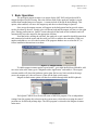
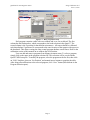
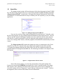
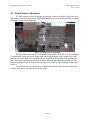
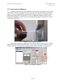
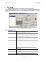
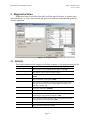
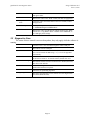
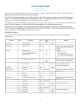
Quad-Pole Magnet Actuator
User’s Manual
Integral Solutions Int'l
– Version 1.1.3 –
June 11, 2010
Phone: (408) 653-0300
Fax: (408) 653-0309
Copyright ©2010 Integral Solutions Int'l
All rights reserved
Integral Solutions Int'l
3000 Olcott St
Santa Clara, CA 95054
Web: http://www.us-isi.com/
E-mail: [email protected]
While every effort has been made to verify the accuracy of the information contained in this publication, this publication may contain technical
and/or typographical errors. Please contact Integral Solutions Int’l to report any errors in this publication.
Quad-Pole Z-Axis Magnet Actuator
Integral Solutions Int’l
June 11, 2010
Contents
1
BASIC OPERATION ................................................................................................................................ 3
1.1
1.2
2
DATA FILES ............................................................................................................................................ 5
RELATED DOCUMENTATION ................................................................................................................... 6
INSTALLATION ....................................................................................................................................... 7
2.1
2.2
2.3
2.4
3
REQUIREMENTS ...................................................................................................................................... 7
ARRIVAL CHECKLIST .............................................................................................................................. 7
CONNECTIONS ........................................................................................................................................ 7
CONFIGURING SOFTWARE ...................................................................................................................... 8
ALIGNMENT & CALIBRATION ........................................................................................................... 9
3.1
3.2
3.3
3.4
4
X ALIGNMENT ........................................................................................................................................ 9
Y ALIGNMENT ...................................................................................................................................... 10
Z LIMIT SENSORS ADJUSTMENT ........................................................................................................... 11
ZERO POSITION CALIBRATION .............................................................................................................. 12
USER MENU ............................................................................................................................................ 13
4.1
4.2
4.3
4.4
5
PROGRAM SELECTION .......................................................................................................................... 13
MANUAL MOVES .................................................................................................................................. 14
ZERO POINT CALIBRATION ................................................................................................................... 14
COMPUTER SETTINGS ........................................................................................................................... 14
DIAGNOSTICS MENU........................................................................................................................... 15
5.1
5.2
6
EEPROM ............................................................................................................................................. 15
DIAGNOSTICS PANE .............................................................................................................................. 16
LIMITED WARRANTY ......................................................................................................................... 17
6.1
6.2
6.3
6.4
6.5
LIMITED WARRANTY ............................................................................................................................ 17
OTHER LIMITS ...................................................................................................................................... 17
EXCLUSIVE OBLIGATION ...................................................................................................................... 17
OTHER STATEMENTS ............................................................................................................................ 17
ENTIRE OBLIGATION ............................................................................................................................ 17
Page 2
Quad-Pole Z-Axis Magnet Actuator
Integral Solutions Int’l
June 11, 2010
1 Basic Operation
The quad-pole magnet actuator is an option for the QST-2002 and quad-pole HGA
magnet designed for HSA testing. Since the uniform field on the quad-pole magnet is much
smaller than standard transverse magnet – it cannot include all heads on the headstack. This
option, when enabled, will move the magnet up and down on head change in Quasi97.
Once set up the magnet actuator will operate in the background and no special actions
need to be taken by the user. Simply select a different head and the magnet will move to the right
place. During production test, Quasi97 iterates through all the heads on the headstack and will
automatically move the magnet to the appropriate location.
Note that before starting the software, the quad-pole z-axis controller should be turned on
and connected to both the motor and the serial port. How to address the controller (COM port
number and address, as well as the location of the program database are saved on the PC, so
follow installation instructions to set those.
Figure 1-1 – Add-Ins Selection
To enable magnet actuator option, open Quasi97, go to Add-InsÆSelected Modules, add
new item in the table, then type in “MagnetActuator.Application” and enable it. The magnet
actuator module will detect the hardware option, then find reverse limit switch on the stage
(move the magnet up!), then will move 0.5mm off the limit switch sensor.
Magnet Actuator menu option will then be available through Add-InsÆPeripherals
Figure 1-2 – Peripherals
Each Quasi97 MDS file will store the name of the HSA program. This is independent
settings from the preamp chip selection in the system menu, which allows reusing the same Z
position sets for different preamp chips. The HSA program is selected in the Magnet Actuator
main menu.
Page 3
Quad-Pole Z-Axis Magnet Actuator
Integral Solutions Int’l
June 11, 2010
Figure 1-3 – HSA program Selection
Each program contains a table with two columns and a row for each head. The first
column has the head number, which corresponds to the head selection in the Quasi97. The
second column is the Z position for that head in micrometers. All testers should be calibrated
such that absolute Z position of 0 corresponds to the same location of the magnet with respect to
the headstack. This allows reusing the same central program database on all testers. Refer to the
calibration section of this manual on to calibrate the Zero Position.
User can add and remove programs from Magnet Actuator menu. To select a program,
simply click on the name in the program selection list. This selection will be saved with the
Quasi97 MDS setup file. To modify the program, select the program on the list first, then click
on “Edit” checkbox, then use “Set Position” and manual moves buttons to populate the table.
After doing all modifications to the selected program, click “Save” button (blue diskette in the
Program Selection pane).
Page 4
Quad-Pole Z-Axis Magnet Actuator
Integral Solutions Int’l
June 11, 2010
1.1 Data Files
The magnet actuator option will store the name of the selected program in Quasi97 MDS
file. The name of the program refers to a set of positions defined in another database (by default
“MagnetActuatorDB.xml”, located in the C:\Program Files\Integral Solutions Int’l\Side Field).
This database is in xml format and can easily be edited by the user separately, by any text editing
application.
Figure 1-4 – Editing the MagnetActuatorDB.xml
User can also switch to using centralized database file on the network. To do this, create
the file on the network (or copy existing magnetactuatordb.xml), then on the tester PC, click on
“Browse for DB” button in the Magnet Actuator user menu, and select the file on the network.
Once the file is loaded, you should see all of the programs in the program selection list. Next
Click “Save Settings (INI)” button, so that the program will load this file automatically next time
it starts.
The MagnetActuator.INI contains the settings necessary to communicate to the Z-axis
controller box. The file is located in the same folder as the magnetActuator.dll (by default
C:\Program Files\Integral Solutions Int’l\Side Field). This file also contains the path to the
program database file (magnetactuatorDB.xml). The following screenshot is an example of INI
file contents.
Figure 1-5 – MagnetActuator.INI file contents
Some of the motor settings, as well as the serial number of the option and the Zero
Position are stored in the EEPROM in the Quad-Pole Z-Axis Controller module. This means
that computer can be substituted and Zero Point position does not need to be recalibrated. To
view these settings click on “Diagnostics” menu, and type in the password “Quasi97”. Refer to
the diagnostics menu section of this manual for more information.
Page 5
Quad-Pole Z-Axis Magnet Actuator
Integral Solutions Int’l
June 11, 2010
1.2 Related Documentation
Quasi97 Software
User’s Manual
Contains detailed description of all menus in Quasi97 software,
along with procedures on how to set up test parameters, log data,
and run the QST in production and engineering modes.
QST External Modules
User’s Manual
Description of additional tests provided with the QST and Quasi97
software.
Quad-Pole Magnet
Option.pdf
Contains specific on the operation of the quad-pole magnet.
Page 6
Quad-Pole Z-Axis Magnet Actuator
Integral Solutions Int’l
June 11, 2010
2 Installation
2.1 Requirements
•
•
•
115VAC
1 USB port on the PC
QST-2002
2.2 Arrival Checklist
1. Check that the magnet actuator stage with the motor is included in the package (if
shipped together with quad-pole magnet option – the magnet will be attached to
the actuator).
2. Check that USB and AC power cables for the Z-Axis Controller are included in
the package.
2.3 Connections
Z-Axis Controller
USB
To computer (digital IO)
SubD-15
To the motor
AC Power
To 115VAC power outlet
Page 7
Quad-Pole Z-Axis Magnet Actuator
Integral Solutions Int’l
June 11, 2010
2.4 Configuring Software
1. Install Quad-Pole Magnet Actuator option software. (This is separate installation
from Quasi97)
2. Plug in the USB cable to the computer. When prompted to install driver, point device
manager to c:\Program Files\Integral Solutions Int’l\Side Field\ USB485 Driver.
If no prompt appears after plugging in the USB from the Z-axis controller box, go to
Control PanelÆSystemÆHardwareÆDevice Manager, find a device with the
exclamation point, right click and select “Update Driver”. Then show it to the
USB485 folder. After driver is finished, you will see additional COM port in the
device manager - note the com port number.
3. Start Quasi97, open any MDS setup file, go to Add-InsÆSelected modules and add
“MagnetActuator.Application”. Then close the menu. You may encounter errors
during this step.
4. Go to Add-InsÆPeripheralsÆMagnet Actuator. In the lower right corner of the
menu, select appropriate COM port (from Step #2). Then click “Save Settings (INI)”
button.
Figure 2-1 – COM Port Selection
5. Reopen the same setup file, and when prompted click “Yes” to save changes.
6. Check the Magnet Actuator menu and ensure that “Hardware Flag” is not red.
7. By default the software will refer to the MagnetActuatorDB.xml file located in the
same folder as the magnetactuator.dll. However, if desired, user can set up the
software such that it looks up the program from centralized network location. To do
this in the Magnet Actuator menu, click “Brows for DB” and select the xml file on
the network. Once finished, click “Save Settings (INI)” button.
Page 8
Quad-Pole Z-Axis Magnet Actuator
Integral Solutions Int’l
June 11, 2010
3 Alignment & Calibration
3.1 X Alignment
If this option replaces standard (transverse) magnet, then user must mount a special
adaptor on the carriage, because the location of the poles on the 4-pole magnet is further away.
Figure 3-1 – Tooling Adaptor for the Quad-Pole Magnet
For different length headstacks (distance from the pin to the head), user needs to readjust
the hard stop on QST-2002, such that the heads come inside the pole area.
Figure 3-2 – X Alignment
Page 9
Quad-Pole Z-Axis Magnet Actuator
Integral Solutions Int’l
June 11, 2010
3.2 Y Alignment
The Y position of the headstack may also differ for different program. To adjust it, use
the 4 screws holding the quad-pole stage on the qst-2002 base plate. When properly adjusted, the
heads will be right in the center of the magnet gap.
Figure 3-3 – Y Alignment (front and back)
Page 10
Quad-Pole Z-Axis Magnet Actuator
Integral Solutions Int’l
June 11, 2010
3.3 Z Limit Sensors Adjustment
The limit sensors are used to stop the stage before it runs out of stroke. The top (reverse)
limit sensor is also used for homing. When changing the reverse limit sensor position, user needs
to redo the Zero position calibration.
Figure 3-4 – Z limit sensors adjustment
The limit sensor indicators are located on the main menu, next to the Z+Z- arrow buttons.
To adjust these, loosen the screws on the limit sensor flag as shown on the picture above and
manually move the stage to the end of the stroke (at least 0.5mm shy of the stage reaching the
end). Then secure the limit sensor flag at the point where the limit indicator just turns on. The
limit has small hysteresis, so slowly move the flag from “OFF” to “ON”, and only at that point
secure it.
As verification, move 1000um away from the limit and then back and ensure that limit
activates first (before reaching the end of the stage).
Page 11
Quad-Pole Z-Axis Magnet Actuator
Integral Solutions Int’l
June 11, 2010
3.4 Zero Position Calibration
When the software starts, it will find home (reverse limit sensor). However the position
of this limit is not precise enough to be able to reuse the same sets of positions across several
testers. In order to enable using the same positions across several testers, the magnet actuator
option has a setting called “Zero Position”. This is a calibration parameter, which is set by
mounting 0.25inch bar on 0.5inch spacer, and centering the magnet such that the bar is in the
center of the magnet gap.
Figure 3-5 - Zero Position Calibration
Mount the bar as shown in the picture above and then use the manual move Z+ and Zbuttons to move the magnet such that the bar is in the center of the gap. At that point click on
“Set Zero Position”. You will notice that the position counter would show 0 at that point.
Figure 3-6 – Zero Position Alignment
Page 12
Quad-Pole Z-Axis Magnet Actuator
Integral Solutions Int’l
June 11, 2010
4 User Menu
Magnet Actuator user menu (or main menu) is accessible through AddInsÆPeripheralsÆMagnet Actuator <SN>. This menu is for selecting the HSA program for the
currently open MDS setup file, and can be used for setting up different programs or for manual
moves.
Figure 4-1 – Magnet Actuator User Menu
4.1 Program Selection
Program List
Use to select a program for the currently opened MDS setup file.
Also use this if you need to edit the program.
“Edit Program”
Will enable the controls so that user can edit currently selected
program. User can then change the name of the program through
the textbox just below the “Edit Program” checkbox. Once finished
editing the program, click on “Save” button.
Heads
This shows how many head positions are set up in this program (or
how many rows there are in the table). To change number of heads,
click “Change” button next to it.
Head Position
table
The first column shows the head number and the second the
position in um. The cursor on the left side of the table allows you to
see which positions you are currently modifying (for set position, or
move To buttons.
Set Position
Will set the position to be whatever the current position of the Z
stage is, for the currently selected row in the Head Position Table.
Move To
Will move to the position shown in the selected row in the Head
Position Table.
Save Button
Will save the program and uncheck the “Edit” checkbox.
Add
Will ask user to type in a new name for the program, then add a
copy of the currently selected program with a new name.
Remove
Will remove the currently selected program from the database.
Page 13
Quad-Pole Z-Axis Magnet Actuator
Integral Solutions Int’l
June 11, 2010
4.2 Manual Moves
Hardware Status
If this square is gray, then hardware is operating normally. Red
indicates that hardware is either not detected, or failed at some
point. The software can detect power off conditions, so if the power
was interrupted, the software needs to be restarted. To do this,
simply reopen the MDS file in Quasi97.
Step
The jog step in um to use when clicking on the “Z+” and “Z-“
buttons.
Current Position
This is normalized position of the Z stage, in um. Note that this is
based on the Zero Position setting.
Find Home
Will move the stage all the way to the top limit and then back
0.5mm. There is no need to do this, unless the motor coupling slips
or the motor missteps (due to low power or obstacle in the travel
path).
Move To Zero
Moves the stage to Zero Point position.
Z+
Will move the magnet UP the amount indicated in the “Step”
textbox. Will not move if the top limit sensor is ON.
Z-
Will move the magnet DOWN the amount indicated in the “Step”
textbox. Will not move if the bottom limit sensor is ON.
STOP
Will cancel any “Move” commands in progress (such as if homing
cannot be completed).
Limits
In real time shows the status of limit sensors. Use these to adjust the
limit sensor positions.
4.3 Zero Point Calibration
Set Zero Point
Click this button only after you align the magnet with the stage (as
indicated in earlier sections of this manual).
4.4 Computer Settings
These pane contains are the settings saved on the computer, in the magnetactuator.ini file.
Port #
This is the COM port number, where to look for Z axis controller.
Actuator Address
The address should be set to 1.
Browse for DB
Allows user to select a different XML database for looking up HSA
programs.
Save Settings (INI)
Saves the settings in this pane to the magnetactuator.ini file.
Page 14
Quad-Pole Z-Axis Magnet Actuator
Integral Solutions Int’l
June 11, 2010
5 Diagnostics Menu
Diagnostics menu is accessible from the User Menu (top left corner). It contains some
motor parameters, as well as zero position and some tests useful for troubleshooting problems
with the equipment.
Figure 5-1 - Diagnostics Menu
5.1 EEPROM
These pane contains are the settings saved on the computer, in the magnetactuator.ini file.
Running Current
The current in % to be applied during the move. [100]
Holding Current
The current in % to be applied when the motor is idle [10]
Micro Stepping J
The number of micro-steps in a full step. [32]
O Value
The parameter that helps to reduce audible motor oscillations.
[1480]
Serial Number
The serial number of the option. [0000]
EEPROM Version
The software version that was used to program the eeprom. Older
software versions will recognize bigger number and will not run
with newer settings. [1]
Velocity
Velocity in uSteps/Sec. [100000]
Home Velocity
Velocity used during homing in uSteps/Sec. [100000]
Acceleration
Acceleration used during normal moves. (This setting multiplied by
6000 will give uSteps/Sec2 acceleration). [100]
Home Acceleration
Acceleration used during homing. (This setting multiplied by 6000
will give uSteps/Sec2 acceleration). [100]
Steps / um
The conversion factor from steps to um. [3.2]
Zero Position
The zero position setting (in um) [0]
Page 15
Quad-Pole Z-Axis Magnet Actuator
Integral Solutions Int’l
June 11, 2010
Write
Stores the values (that are in the “Write” column) to the EEPROM
and applies them.
Read
Restores the values to the “Read” column, but does not apply them.
Copy Read To
Write
Copies the values from read column to the write column, but does
not apply them.
INI Backup
Backs up the eeprom contents (write column) to the
“\..\EEPROMS\MagnetActEEPROM.ini”.
INI Restore
Restores the values from the INI file and puts them into the “Read”
column. Use “Copy Read to Write” and then “Write EEPROM” to
save and apply these settings.
5.2 Diagnostics Pane
The status of these controls is not saved anywhere; they only apply while the software is
running.
Connect
Connects to the z-axis controller through the enable COM port.
Disconnect
Disconnects from the COM port
SEND
Will send the command to the controller (shown above in the text
box). Do not include the addressing (“/1”), as it will be appended
automatically.
Track COM
Will trace the communication on the COM port and put the contents
in the list box besides it. To clear the textbox, double-click on it.
Test Positioning
Will start the test that will move from Point A to Point B, then wait,
then move back and wait.
Random
Instead of moving to “From” and “To”, will move to some random
position between these two points.
Abort
Aborts the test positioning algorithm.
Ignore QST Events
Will ignore the Head Select event (will not move the magnet when
user selects different head).
Page 16
Quad-Pole Z-Axis Magnet Actuator
Integral Solutions Int’l
June 11, 2010
6 Limited Warranty
Integral Solutions Int'l, a California Corporation, having its principal place of business at
3000 Olcott St, Santa Clara, CA 95054 ("Manufacturer") warrants its Quasi-Static Tester model
QST-2002 products (the "Products") as follows:
6.1
Limited Warranty
Manufacturer warrants that the Products sold hereunder will be free from defects in material and workmanship
for a period of six (6) months from the date of purchase. If the Products do not conform to this Limited Warranty
during the warranty period (as herein above specified), Buyer shall notify Manufacturer in writing of the claimed
defects and demonstrate to Manufacturer satisfaction that said defects are covered by this Limited Warranty. If the
defects are properly reported to Manufacturer within the warranty period, and the defects are of such type and nature
as to be covered by this warranty, Manufacturer shall, at its own expense, furnish replacement Products or, at
Manufacturer's option, replacement parts for the defective Products. Shipping and installation of the replacement
Products or replacement parts shall be at Buyer's expense.
6.2
Other Limits
THE FOREGOING IS IN LIEU OF ALL OTHER WARRANTIES, EXPRESS OR IMPLIED,
INCLUDING BUT NOT LIMITED TO THE IMPLIED WARRANTIES OF MERCHANTABILITY AND
FITNESS FOR A PARTICULAR PURPOSE. Manufacturer does not warrant against damages or defects arising
out of improper or abnormal use of handling of the Products; against defects or damages arising from improper
installation (where installation is by persons other than Manufacturer), against defects in products or components not
manufactured by Manufacturer, or against damages resulting from such non-Manufacturer made products or
components. Manufacturer passes on to Buyer the warranty it received (if any) from the maker thereof of such nonManufacturer made products or components. This warranty also does not apply to Products upon which repairs
have been affected or attempted by persons other than pursuant to written authorization by Manufacturer.
6.3
Exclusive Obligation
THIS WARRANTY IS EXCLUSIVE. The sole and exclusive obligation of Manufacturer shall be to
repair or replace the defective Products in the manner and for the period provided above. Manufacturer shall not
have any other obligation with respect to the Products or any part thereof, whether based on contract, tort, strict
liability or otherwise. Under no circumstances, whether based on this Limited Warranty or otherwise, shall
Manufacturer be liable for incidental, special, or consequential damages.
6.4
Other Statements
Manufacturer's employees or representatives' ORAL OR OTHER WRITTEN STATEMENTS DO NOT
CONSTITUTE WARRANTIES, shall not be relied upon by Buyer, and are not a part of the contract for sale or this
limited warranty.
6.5
Entire Obligation
This Limited Warranty states the entire obligation of Manufacturer with respect to the Products. If any part
of this Limited Warranty is determined to be void or illegal, the remainder shall remain in full force and effect.
Page 17