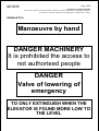
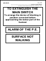
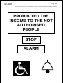
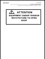
1
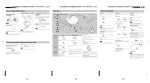
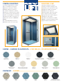
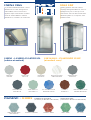
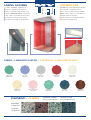
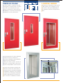
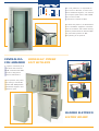
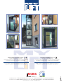
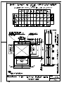
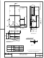
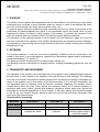
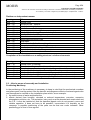
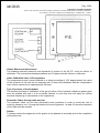
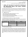
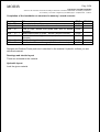
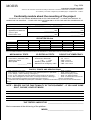
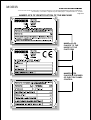
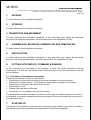
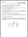
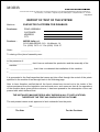
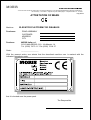
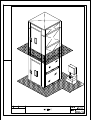
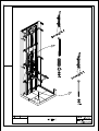
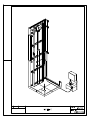
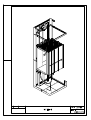
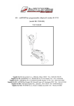
PIATTAFORME ELEVATRICI OLEODINAMICHE HYDRAULIC LIFTING PLATFORMS MY LIFT è la piattaforma elevatrice ideale per l'abbattimento delle barriere architettoniche, consentendo di migliorare la qualità della vita perché facilita la mobilità' non solo di persone anziane o disabili. E' conveniente perche' i costi di acquisto e di esercizio sono contenuti, e' elegante e personalizzabile perche', oltre alla ricca dotazione di serie, sono disponibili numerosi colori, accessori e combinazioni. Ogni MY LIFT e' fornito di pulsanti braille e corrimano e particolare attenzione viene riservata alle dotazioni di sicurezza di serie e in opzione. MY LIFT is the hydraulic lifting platform ideal for removing architectonic barriers, allowing quality of life to be improved as it aids mobility, not just for the elderly or disabled. Profitable because purchase and maintenance costs are low, it is stylish and adaptable because apart from the comprehensive standard equipment, a variety of colours, accessories and combinations are available. Each MY LIFT is supplied with Braille push buttons and handrail and special care is reserved to safety devices, standard and an option. MY LIFT, disponibile nella versione per utenti disabili e nella versione PE per villette unifamiliari, é la risposta su misura per il superamento di barriere architettoniche, in linea con le specifiche necessità dell’utilizzatore. La sua installazione non richiede grandi interventi strutturali, garantisce la massima sicurezza, utilizzando le tecnologie più avanzate ad un costo decisamente contenuto. Ogni piattaforma MY LIFT é un esemplare unico, personalizzata in base alle misure ed ai rilievi del luogo di installazione. L’elevatore si integra gradevolmente con l’ambiente, armonizzandosi con l’arredamento. MY LIFT, available in the type for disabled people and in PE type for onefamily houses, the tailor-made answer for overcoming the architectural barriers, according with the specifications needed by the user. Its installation does not require great structural interventions; it grants the maximum safety, using the most advanced technologies, at a decidedly controlled cost. Each MY LIFT platform is a unique specimen, personalized according to measures and characteristics of the installation site. The elevator integrates easily with the environment, harmonizing with the furniture. CABINA ELECTRA ELECTRA CAR I numerosi abbinamenti di colori, oltre a soddisfare le esigenze dell'utente, rendono la cabina ELECTRA brillante e luminosa. La cabina è realizzata in lamiera plastificata, i pavimenti sono vinilici con granuli di quarzo, illuminazione al neon a controsoffitto o con faretti annegati nel cielino. Le finiture di cabina sono di serie in SIMILINOX F12PPS. La cabina ELECTRA può essere realizzata anche con acciai inox. The great number of colours couplings, besides satisfying the requests by our customers, make ELECTRA car brilliant and bright. ELECTRA car is made from plasticized plate, floors are made from vinyl with quartz granules, lighting with neon under ceiling or spotlights in the ceiling. Car finish, as standard, is in INOX F12PPS; on request stainless steels may be used to make the car. CABINE - LAMIERA PLASTIFICATA • CAR WALLS - PLASTICIZED PLATE AZZURRO B1 LIGHT BLUE B1 SABBIA A3 SAND A3 SIMILINOX F12 PPS INOX F12 PPS BIANCO A1 WHITE A1 BIANCO ANTICO DT29 SMA ANCIENT WHITE DT29 SMA BLU STELLATO B41 SMM STARRY BLUE B41 SMM CREMA G1 CREAM G1 GRIGIO ANTRACITE N4 DARK GREY N4 GRIGIO CHIARO N1 LIGHT GREY N1 VERDE CHIARO V14 LIGHT GREEN V14 PAVIMENTI • FLOORS SABBIA SAND GRIGIO GREY BLU BLUE VERDE GREEN NERO BLACK GOMMA NERA A BOLLE BLACK RUBBER, BUBBLES CABINA VEGA VEGA CAR La posizione dell’illuminazione e nuovi abbinamenti di colori distinguono la cabina VEGA; neon o faretti sono applicati sopra la bottoniera di cabina. Anche la cabina VEGA è in lamiera plastificata o, a richiesta, in acciaio inox. Lighting position and new colours couplings distinguish VEGA car; neon or spotlights are put on the top of car push button. This car also is made from plasticized plate or, on request, from stainless steel. CABINE - LAMIERA PLASTIFICATA (cabina standard) GRIGIO PPS1 GREY PPS1 ROSSO F3 SM RED F3 SM GRIGIO SCURO N21 DARK GREY N21 GRIGIO-AZZURRO CHIARO LIGHT GREY-BLUE AVORIO PPS15 IVORY PPS15 VERDE CHIARO V 14 LIGHT GREEN V 14 PAVIMENTI • FLOORS CAR WALLS - PLASTICIZED PLATE (standard cars) BIANCO VENATO PPS13 VEINED WHITE PPS13 BLU SPAZZOLATO PPS30 BRUSHED BLUE PPS30 SIMILINOX F12 PPS INOX F12 PPS CUOIO DP 4 LEATHER DP 4 VERDE SPAZZOLATO PPS29 BRUSHED GREEN PPS29 PAVIMENTI IN LINOLEUM LINOLEUM FLOORS (standard per MY LIFT e MY LIFT PE) (standard for MY LIFT and MY LIFT PE) ANTRACITE • DARK GREY MARRONE • BROWN VERDE • GREEN BLU • BLUE CABINA ANTARES ANTARES CAR La cabina ANTARES, raffinata ed elegante, è realizzata in laminato plastico. Le finiture della cabina sono di serie in SIMILINOX F12PPS, a richiesta in altri colori o materiali come l’acciaio inox. Possono essere richiesti altri colori diversi da quelli in campionario. ANTARES car, distinguished and stylish, is made from laminated plastic. The car has a standard finish in INOX F12PPS, other colours or materials as stainless steel on request. Further colours are available besides those in the sample case. CABINE - LAMINATO PLASTICO • CAR WALLS - LAMINATED PLASTIC VERDE 2408 GREEN 2408 BLU 2421 BLUE 2421 AVORIO 2525 IVORY 2525 GRIGIO 2401 GREY 2401 ROSA ANTICO 2569 PINK 2569 PAVIMENTI • FLOORS DISPONIBILI A RICHIESTA AVAILABLE ON REQUEST ROSSO 2201 RED 2201 VERDE 2539 GREEN 2539 PAVIMENTI GRANITO (solo per MY LIFT PE) BIANCO 1907 WHITE 1907 BLU 2202 BLUE 2202 GRANITE FLOORS (only for MY LIFT PE) RADICA 1835 BRIER 1835 PORTE DI PIANO LANDING DOORS Le porte di piano, in lamiera d'acciaio, antiruggine o verniciata RAL o rivestite in acciaio, sono disponibili in ampia gamma di dimensioni, cieche (normali o REI 60-120) o con finestra di dimensioni variabili fino al vetro panoramico. Landing doors, steel plate made, primed or RAL painted, are available in many dimensions, blind (also REI 60-120) or with different windows until panoramic glass. La porta panoramica con anta in alluminio e telaio in acciaio e' sinonimo di robustezza, flessibilita' nell'installazione, eleganza in ogni ambiente. Il telaio puo' essere grezzo, rivestito in alluminio o verniciato RAL come l'anta. La porta e' disponibile in tutte le misure. The door with panoramic window with aluminium shutter and steel frame is synonymous with sturdiness, flexibility of installation, elegance in any setting. the frame can be unfinished, aluminiumcoated or RAL-painted to match the door. The door is available in all sizes. Per chi la preferisce, e' disponibile la porta tutta in alluminio; di serie viene fornita anodizzata argento, con chiusura a scomparsa (nelle misure 750 e 800 mm) e fermo a 90°. In opzione la verniciatura RAL. For those who prefer it, an all-aluminium door is available; supplied in anodized silver as standard, with hidden locking feature (measurements 750 and 800 mm) and fixed position at 90°. RAL painting is an optional. CENTRALINA CON ARMADIO HYDRAULIC POWER UNIT WITH BOX In opzione, l'armadio per la centralina nella versione HL/AR, verniciato RAL 7032, garantisce eleganza e massima silenziosita'. As an optional, the power unit casing in the HL/AR version, RAL 7032 painted, guarantees elegance and maximum quiet. QUADRO ELETTRICO ELETRIC BOARD PIATTAFORME ELEVATRICI MYLIFT ® LIFTING PLATFORMS MYLIFT ® Ai sensi delle Direttive Comunitarie 89/392/CEE-89/336/CEE-92/91/CEE-73/23/CEE-93/96/CEE-93/42/CEE e successive integrazioni e modifiche e a ISO 9386-1. According to the EC Directives 89/392/CEE-89/336/CEE-92/91/CEE-73/23/CEE-93/96/CEE-93/42/CEE and following supplements and modifications and ISO 9386-1. LE FOTO, I DISEGNI E I COLORI HANNO VALORE INDICATIVO E NON VINCOLANTE. MORIS ITALIA SI RISERVA DI APPORTARE MODIFICHE SENZA PREAVVISO. LE FOTO, I DISEGNI E I COLORI HANNO VALORE INDICATIVO E NON VINCOLANTE. MORIS ITALIA SI RISERVA DI APPORTARE MODIFICHE SENZA PREAVVISO. MORIS MORIS italia s.r.l. Via Mazzini, 51 • 21023 MALGESSO (VA) • Italy • Tel. 0039-0332787011 • Fax 0039-0332706437 Via Como, 15 • 21020 MONVALLE (VA) • Italy • Tel. 0039-0332799024 • Fax 0039-0332798028 www.moris.it • e-mail: [email protected] DESK SWITCHBOARD C 224 690 858 9 198 * * 40 380 ø * 0946/I-... C DET. X 40 1493 635 0946/S A 770 B 50 740 A B SECTION C-C SCREW TCEI M8x15 NR 4 WASHER ø 9 STANDARD OPEN DOORS DX/SX DET. X TANK PATTERN A B HL/300 355 405 HL/420 475 525 FIGURE N° GROSS WEIGHT Kg 0946/S 30 0946/I-300 80 0946/S 30 0946/I-420 90 *- OIL PIPES AND ELECTRIC CABLES OUTPUT PAINTING RAL 7032 (ORANGE PEEL) CABINET ASSEMBLY FOR TANKS: AR/HL 9681-IN DATE 01/02 DWG NR. 9681 MORIS italia s.r.l. Machine Hydraulic Reducer Special Systems Via Mazzini, 14 - 21023 MALGESSO (VA) - ITALIA Tel. (0332) 78 70 11 - Fax (0332) 70 64 37 HANDBOOK FOR THE INSTALLATION AND THE MAINTENANCE - OF THE FITTER ELEVATOR PLATFORM FOR DISABLE WARNINGS The present manual is destined to the fitter of the platform. Before installing or carrying out actions of maintenance of the platform to read with attention the present document and the manual customer it leave integrating of the present document. The parts, which are not closely linked to these instructions, are only for information and clarifications. After the installation you must deliver the documentation of the case following the next information. ELEVATOR PLATFORM FOR DISABLE - this is the user manual of construction according to attachment V of directive 89/392/CEE and following modifications - do not destroy - do not alter - integrate only with added pages - compilation date 13.06.00 MORIS Pag. 2/24 ELEVATOR PLATFORM FOR DISABLE - This is the user manual of construction according to attachment V of directive 89/392/CEE and following modifications - do not destroy - do not alter - integrate only with added pages - compilation date 13.06.00 - INDEX: a. Characteristics of the machine p. 03 b. Card of technical data p. 04 c. Definition of the terms used p. 04 01. Packing p. 05 02. Storage p. 05 03. Transport and movement p. 05 04. Assemblage, mounting, dismantling and remounting p. 06 05. Installation p. 08 06. Normal use and particular functioning (foreseen and reasonable predictable). Incorrect and unforeseen use. Malfunction, fault, damage. Individual machine protection. p. 17 07. Cleaning and spare parts p. 18 08. Setting and calibration p. 18 09. Maintenance, inspections and checks, reparation p. 18 10. Control of corrected installation and relative documentation p. 19 11. Attached tables p. 20 Module of conformity of the assembly to the plan p. 22 12. Annotations and recommendation p. 23 Attached: • Outline power pack to unifilar • Hydraulic outline of the system • Total design of the system and Tables of assembly (you see detail directory) • Elevator platforms for disables: Documentation of the platform and handbook customer instructions for the use (documentation to deliver to the completed customer the assembly and the control) MORIS Pag. 3/24 ELEVATOR PLATFORM FOR DISABLE - This is the user manual of construction according to attachment V of directive 89/392/CEE and following modifications - do not destroy - do not alter - integrate only with added pages - compilation date 13.06.00 - a. CHARACTERISTICS OF THE MACHINE The elevator platforms, described in this handbook, are constructed to art rule in order to allow the overcoming of an uneven to the persons with reduced or prevented mobility. These elevator platforms are concurred in via alternative to lift in the participation of adaptation or in order exceeding contained differences of quota in the private buildings in construction or restructure, let alone in the external spaces whose plans have been introduced after the 11 day August 1989. Said platforms they are constituted from a mobile structure, bringing the cargo platform that it slides on two fixed guides on a wall of a closed space that can be constructed in whichever resistant material and must guarantee the protection of the system from the atmospheric agents. The constructor cannot be considered responsible for eventual damages caused from use and/or improper, erroneous and not reasonable installation and/or maintenance that must be carried out following the prescription of which to the present held document account of the norms of good technique. The elevator platforms for disable are composed substantially by: • Hydraulic piston. • Hydraulic power pack. • Electric panel control. • Cabin lacking in doors. • Doors to the plans. • Guides and eventually rammer. The elevator platforms for disable are equipped of: • Apparatus parachute that timely blocks the platform on the guides in the case verified the slackening or the breach also of one single rope. • Device of emergency against the fast reduction of the cabin. • Device of electromechanical control of emergency of the doors against the opening of the doors in cabin absence. • Device of alarm in cabin. • Automatic or manual device for the reduction of emergency. • Lamp to low tension for the lighting system of the cabin. This elevator platform is in compliance with the following dispositions of law: • Directive Machines 89/392/CEE and following modifications and completions: 91/368/CEE, 93/44/CEE and 93/68/CEE incorporate with the 24 D.P.R. of July 1996 n. 459. • Low directive Tension 73/23/CEE and following modifications and completions: 93/68/CEE incorporate from Law 18 October 1997 n. 791. • Directive Electromagnetic Compatibility 89/336/CEE and following modifications and completions: 93/31/CEE incorporate with D.L. 4th Decembers 1992 n. 476. • Explanatory circular of 14 April 1997 n°157296, for the application of the presidential decree 24 July 1996, n°459, to the freight elevators and the elevator platforms for disable. • Norma ISO 9386-1 elevator Platforms for persons with reduced mobility. • Directive Medical Apparatus 93/42/CEE incorporate with D. Lgs. n. 46/97. MORIS Pag. 4/24 ELEVATOR PLATFORM FOR DISABLE - This is the user manual of construction according to attachment V of directive 89/392/CEE and following modifications - do not destroy - do not alter - integrate only with added pages - compilation date 13.06.00 - b. CARD OF TECHNICAL DATA OF THE PLATFORM On the base of the type of system to which they make service, the elevator platforms come realised on measure in the within of the following dimensions and characteristics: DESCRIPTION Abilities persons Capacity with cabin Speed Traction Stopped Accesses to the cabin Useful race Manoeuvre Feeding Motor power Dimensions of hydraulic power pack Dimensions of picture power pack Standard head Dimensions of footrest Cabin Doors of plan VALUE One person with mobility reduced more a companion 250 Kg 6 m/min In ransom 2:1 From 2 to 4 Until 4 Until 12,70 mt. Present man with emergency 230 V single phase - 400 V three phase Max. 1,8 kW single phase - max. 2,2 kW three phase 600 x 420 x 650 mm 600 x 550 x 220 mm 2550 mm To demand (cabin max 1100 x 1400 mm) Constructed in sheet as plastic, with bottom in Linoleum or rubber to bubbles, illuminated through one lamp to neon embedded in appropriate lamp on the ceiling To a clapper to not visible, half-automatic hinges, with windows in glass, antirust paint job, apparatus mechanic of closing, shock-absorber, external big handle in aluminium Noise emitted by the machine The level of continuous acoustic pressure advised A in the workplace by the operator is usually under 70db. Conformity system power pack The system power pack of the machine is in compliance with norms CEI EN 60204-1 and CEI 44-5. Relative conformity to the Electromagnetic Compatibility The machine is in compliance with the Directive Electromagnetic Compatibility 89/336/CEE and following integration 92/31/CEE and D.L. n°476 of the 04,12,1992. c. DEFINITION OF THE TERMS UTILISED Refer to norm UNI EN 292 for definitions of the terms utilised in this manual. MORIS Pag. 5/24 ELEVATOR PLATFORM FOR DISABLE - This is the user manual of construction according to attachment V of directive 89/392/CEE and following modifications - do not destroy - do not alter - integrate only with added pages - compilation date 13.06.00 - 1. PACKING The closet comes supplied both assembled that not assembled in its members in some packs composed from one base in wood (footrest) and from means in order to immobilise the necks you mail on the footrest (iron hoop, thermo-shrink nylon, etc). To remove thermo-reduction protecting nylon eventually and the iron hoop; to the inside of the protections of plastic/cardboard the parts of not assembled closet are found. After to have unpacked the closet you have to verify integrity of the content. To contact the company in the case the material was not consistent and not to proceed except different indication. The elements of the packing (footrest of wood, plastic nail, belt fasteners, bags, etc.) they do not have to be left to the capacity of the children because they are potential sources of danger. The elements of the packing moreover go stored and placed to refusal following the enforced dispositions of law. 2. STORAGE The elevator platform, in case do not come immediately installed, must be conserved to the inside of them pack in a dry atmosphere, repaired from atmospheric agents and to temperature comprised between 0 °C and 40 °C. The packing must be far placed from sources of heat, flames, etc. The packing must be maintained in a straight position, avoiding overlapping packs one over the other. 3. TRANSPORT AND MOVEMENT The transport of the machine not assembled from the supplier to the installation place happens through truck, or with means of the supplier or through society of road haulage. The drainage from the truck and the movement of packs integral must be carried out through transpallets (to cargo of the supplier) and in the respect of the enforced norm. If it is not had transpallets, the not assembled parts of machine must by hand be unloaded, unpacking the machine and to unload directly from the truck. Some pieces are excessive heavy for a manual transport, in particular steel doors, piston, guides and hydraulic telephone power pack must second be enlivened the enforced dispositions of law in matter. In any case pieces with advanced weight to the 30 kg. are marked through adhesive label and go second enlivened demanded how much from the enforced norm. Characteristics of packing MACHINE Gross weight Dimensions Contained FOOTREST 1 FOOTREST 2 Kg M Panels, mounting, crosspieces, doors FOOTREST 3 Kg M Piston, guides, kit hydraulic Kg M Hydraulic power pack, electrical panel control, electrical material MORIS Pag. 6/24 ELEVATOR PLATFORM FOR DISABLE - This is the user manual of construction according to attachment V of directive 89/392/CEE and following modifications - do not destroy - do not alter - integrate only with added pages - compilation date 13.06.00 - 4. ASSEMBLAGE, MOUNTING, DISMANTLING AND REMOUNTING The assemblage of the members, the mounting, the dismantling and the eventual remounting, in other place, of the platform, must follow the passages previewed in the attached explanatory tables to the manual present. The tables, to which it makes reference re-produce the operations to carry out, are tidy for table number and are completion part of the present instructions. Remember that every operation on the structure or the members of the platform must perfectly be executed from staff authorised acquaintance of all the relative criteria to the norms of good technical norm and that companies the final document of conformity second the previewed technical detailed lists. On the supply of the instructions of continuation supplied the fitter will have to supply to the assembly of the platform. The tables BASE come used for the indication of the assembly sequences. Moreover, beyond to following the prescription, they always go respected the enforced norms and laws in the installation country. Platform on independent frame: Held account: - of the Tav.0894/01 table that represents the general sight of the platform and as the same one will be introduced to the end of the assembly the fitter will choose with particular cures the location of the hydraulic telephone power pack in such way that the position of same the not constrictions in some way income and the escape from the platform. The choice must be carried out of time in time to second of the requirements - - of the Tav.0894/02 table (seen structural metallic – rammer) that it will contain and support the platform. The structure will be composed from four foot straight or mounting reinforced they give of the hardening crosspieces (the distance must be adapted and to allow the disembarkation of the passengers to the pre-established levels) that they act as or from I reinforce and that they guarantee the rigidity of the plan. The fitter will be organised in order to begin the assembly of the structure. The assembly of the platform will have moreover to be put into effect from the fitter second the described sequence of continuation: Tav.0894/02-1: - for the implantation of the base of the platform to mounting through lives bolted in the indicated positions; - for the implantation to earth the platform through lives to pressure; Tav.0894/02-2: - for the implantation between they of mounting with the crosspieces and to the assemblage of the elements carrying lateral with the crosspieces. Moreover in the angular node the lateral auctions that come fixed through lives to the carrying structure and to the node converge. Particular it must be placed in merit to the lives to use. MORIS Pag. 7/24 ELEVATOR PLATFORM FOR DISABLE - This is the user manual of construction according to attachment V of directive 89/392/CEE and following modifications - do not destroy - do not alter - integrate only with added pages - compilation date 13.06.00 - Tav.0894-03 for the implantation of the rope of the arched one and the guides, the piston and the advanced ransom (exploded details to the successive ones that they follow): - Tav.0894/03-1 connection and implantation of the guides and the arched /cylinder. The members of the guides go fixed between they with lives bolted like from the outline (inferior part), while the piston goes fixed with one little square bolted to the structure. In the advanced part there is the implantation of the guides to the structure and the implantation arched /cylinder happens with one screw bolted to the cylinder - Tav.0894/03-2 implantation of the connection of the guides to the rope. The rope it comes mounted around to the piston through bolted lives. The bolt guides come berthed to earth in the indicated way. Tav.0894/04 for the total assembly of the arched one lend particular attention for: - the coupling back that works from anchorage plate; - the two elements carrying connected with one square to the platform door cabin; - the platform door cabin; - the detail on like mounting the dial foot of fine race. The ulterior indications are considered moreover following: Tav.0894/04-01 relative detail to the connection of the arched one. To the support chassis door cabin the anchorage plate goes fixed. The chassis is composed from two mounting connected with a square to the profile of support of the chassis on which then the cabin will be mounted. They come then mounted the two crosspieces of hardening and I reinforce of the profiles door cabin. Tav.0894/05: for the assembly of ropes. Given to the characteristics of the platform ropes the connections come fixed to the chassis door cabin (are particular and second guarantee part of the amortisation) and to rope the indications of which to the table. Tav.0894/06: for the implantation of the platform of the wall of the cabin side guides after to have coupled ropes by means of: - connection of the chassis where you can put inside the cabin - implantation of the parades side guides and the platform where you can put inside the cabin. Moreover the containing wall the guides goes berthed is in the inferior part that in the advanced part. The platform comes instead bolted to the profiles door cabin. Moreover on the supply of the Tav.0894/06-1 to fix the side walls of the cabin. The sidewalls of the cabin are composed from rectangular panels that must together be bolted and that they constitute the wall. The external walls are joined with a profile of reinforce like evidenced in figure. For last it comes then mounted the handrail inside. Tav.0894/07: for the completion of the assembly of the platform with the implantation of the advanced hat of the fixed structure with bolts. This general table previews exploded of the lateral closings and the zone the door contained in while in the Tav.0894/07-01 the lateral closings and the zone are evidenced in detail door. Tav.0894/08 - Tav.0894/09: for place of the feeding of the telephone power pack / piston and the cable power pack. MORIS Pag. 8/24 ELEVATOR PLATFORM FOR DISABLE - This is the user manual of construction according to attachment V of directive 89/392/CEE and following modifications - do not destroy - do not alter - integrate only with added pages - compilation date 13.06.00 - Completion of the installation on structure in masonry / armed concrete. For the completion of the assembly of the platform on structure as over indicated the fitter will have to proceed like of indicated continuation: Tav.0894/10 for the definition of the general conditions of assembly. It is specified moreover that also in such case particular cure in the choice of the location of the hydraulic telephone power pack will have to be placed that does not have dangerous for people that uses the platform. Tav.0894/11 for the corrected definition of the skeleton of the tower in walling/C.A. The holes in order to allow to the income and the escape the platform must be of the previewed dimensions. Tav.0894/12 for the general insertion of the structure in presence of one opening in masonry C.A.). The platform will have to be inserted to the inside of the structure and the connections will have to be those of the three successive ones exploded. - - - Tav.0894/12-1 for the details of the connection and the implantation of the guides and the arched/cylinder. The members of the guides must be fixed between they with lives bolted as from the outline (inferior part), while the piston will have to be fixed with one little square bolted to the structure. In the advanced part there is the implantation of the guides to the structure and the implantation arched/cylinder happens with a screw bolted to the cylinder as evidenced from the design - all it then comes fixed on the walling structure through lives to pressure to second use the instructions given from the manufacturers in the technical documentation linked (depth of implantation - conditions regarding the characteristics of the walls - carrying capacity - etc) Tav.0894/12-2 for the details of the connection guides to rope and to the walling structure. The rope it comes mounted around to the piston through bolted lives. The bolted guides must be berthed to earth in the indicated way Tav.0894/12-3 for the details of the implantation of the connection of the guides to the rope. The rope she comes mounted around to the piston through bolted lives. The bolted guides come berthed to earth in the indicated way. Tav.0894/13 for the detail of the anchorage particular of the door through a dowel to pressure to place you must follow the instructions given from the supplier 5. INSTALLATION 5.1. - Designs for the sequence of installation The installation must second be carried out the instructions of which to point 4 held account of the outline of tables of indicated continuation (tables BAS serve for the sequence of the assembled). MORIS Pag. 9/24 ELEVATOR PLATFORM FOR DISABLE - This is the user manual of construction according to attachment V of directive 89/392/CEE and following modifications - do not destroy - do not alter - integrate only with added pages - compilation date 13.06.00 - Platform on independent rammer Drawing 0894 – 01 0894 – 02 0894 – 02 – 1 0894 – 02 – 2 0894 – 03 0894 – 03 – 1 0894 – 03 – 2 0894 – 04 0894 – 04 – 1 0894 – 05 0894 – 06 0894 – 07 0894 – 07 – 1 0894 – 08 0894 – 09 Title General view Structural view – rammer Details for linking the base Details for mounted linking View rope – arched and guides Details of links about guides arched / cylinder Details of links about the guide rope View of structured arched Details about structural links Card ropes Platform and wall of cabin – side guide General view with hat assembling Details about lateral locking and about the doors area Layout about electrical exchange and piston Layout about electric cable Completion of the installation on a walling structure / reinforced concrete Drawing 0894 – 10 0894 – 11 0894 – 12 0894 – 12 – 1 0894 – 12 – 2 0894 – 12 – 3 0894 – 13 Title General view (in walling) View about walling tower and / or reinforced concrete View about rope, arcade and guides (walling and / or reinforced concrete Details of links about guides – arcade (reinforced concrete) Details of links about guide connected to rope (reinforced concrete) Details of links about guide arcade (walling) Details about the anchorage door (walling and reinforced concrete) 5.2. - Ulterior norms of assembly and installation Positioning Machinery In the positioning of the machinery is necessary to keep in mind that the mechanical members and power pack must be protect from the harmful and dangerous effects of external agents who can themselves be verified on the installation place which, as an example: 1. the solid income of water and bodies the 2. effects derived from humidity, elevated or reduced temperature, corrosion, excessive atmospheric pollution, etc. The protection (vain race) must be planned and constructed and the P.E. it must be installed so that the specified agents over do not prevent a sure and reliable operation. It does not have to be possible I accumulate it of humidity on the raceways. A possible positioning of the parts can be that one under indicated. Other positioning go of time in time agreed. MORIS Pag. 10/24 ELEVATOR PLATFORM FOR DISABLE - This is the user manual of construction according to attachment V of directive 89/392/CEE and following modifications - do not destroy - do not alter - integrate only with added pages - compilation date 13.06.00 - Values Games and unevenness The distance between protection and threshold of income of the 20 P.E. must be inferior to millimetre. The unevenness between platform and 10 plans must be inferior to millimetre. Value Calibration Valve of Overpressure The overpressure valve comes calibrate to a value exceeding of 10% approximately the value of the pressure of full load (as an example with 23 bars the calibration with the overpressure valve comes carried out to approximately 26 bars). Type of process of lead sulphate The several positions of calibration of the group valves of the hydraulic telephone power pack must be marked with use it of a not delete varnish, in such way that can easy be verified eventual tampering or intervention on the regulations. Protection Tubes through walls and not The hydraulic tubes do not have adequately been protected in order to avoid the risk of crushing, abrasion, etc. Curving with beams too much tightened - at least 10 times the diameter of the tube must be avoided. Guides To always control the alignment of the guides in the phases of assembly and to the completion of the same one. MORIS Pag. 11/24 ELEVATOR PLATFORM FOR DISABLE - This is the user manual of construction according to attachment V of directive 89/392/CEE and following modifications - do not destroy - do not alter - integrate only with added pages - compilation date 13.06.00 - Prescription for Electrician 1. To do an adapted system of grounding. 2. To install in the computer room a power pack with feeding to 230/250 V alternated with interrupting differential and magneto-thermo. 3. The lighting system on the surface of the landing of the footrest and on the device of commando must be controlled from an adjacent switch to measure the 50 P.E. and light does not have to be inferior to on their surface. 4. Sufficient lighting system of the computer room must be guaranteed one. 5. Must be installed of the taken power pack of escape on the picture of the computer room, on the bottom ditch of the P.E. and on the landing of disembarkation of the P.E. in proximity of the doors of the same one. 6. To accurately control the positions of the extra-race. Threshold and Ramp If the platform is planned for stopping to a level situated to of over of the surface of the landing inferior, going in such a way to constitute a 15 unevenness that exceeds the millimetre, then the system of one ramp of plan must be equipped. Such ramp it must have a not advanced inclination to: - 1:4 on a vertical rising until 50 millimetre - 1:6 on a vertical rising until 100 millimetre - 1:12 on a vertical rising beyond 100 millimetres. 5.3. - Trusts and warnings to place in the p.e. It is necessary to expose on the platform of the warnings bringing like minimum the following information: a) the nominal capacity in kilograms and the maximum number of transported persons; b) the name of the constructor, the number of series and the year of installation. The device of emergency alarm must be of yellow colour and must be marked with a symbol to bell shape. The device of arrest of emergency of which to point 1.9.2.3 (of norm 9386) must be of red colour and must be marked from word STOP. A symbol of disable person to every income must be exposed. The height of such symbol must be at least 50 millimetres. In the external part of doors, trap doors etc that it gives approached the machinery must apply one bringing nameplate the following words: DANGER - MACHINERY It is prohibited the access to persons not authorised On the body machine they must be brought back of the instructions detailed for the manual manoeuvre of emergency. MORIS Pag. 12/24 ELEVATOR PLATFORM FOR DISABLE - This is the user manual of construction according to attachment V of directive 89/392/CEE and following modifications - do not destroy - do not alter - integrate only with added pages - compilation date 13.06.00 - In the case of systems with hydraulic transmission, nameplate must be applied one next to the valve of manual lowering: DANGER Valve of lowering of emergency The switch for the feeding main power pack of the elevator must have a mark. In the case of P.E. with hydraulic transmission, the switch must be marked with the following words: TO ONLY EXTINGUISH WHEN THE ELEVATOR IS FOUND CLOSE TO LOW LEVEL In the income to the below part of the platform to the entry point, must be applied to a bringing nameplate the instructions for a sure use of the device of specified mechanical blocking to point 1.5.3, as an example: TO EXTINGUISH the MAIN SWITCH To arrange the device of blocking in position corrected before approaching the below part of the footrest. The alarm beacon of which to point 1.9.2.4.1 it must bring the following words: ALARM OF THE P.E. The not usable of the ceiling must be marked with a vertical trust indicating SURFACE NOT WALKING To the outside and the inside of the power pack to place: ATTENTION EQUIPMENT UNDER TENSION WITH PICTURE TO OPEN SHOP MORIS Pag. 13/24 ELEVATOR PLATFORM FOR DISABLE - This is the user manual of construction according to attachment V of directive 89/392/CEE and following modifications - do not destroy - do not alter - integrate only with added pages - compilation date 13.06.00 - SEGNALETICA Manoeuvre by hand (To place close to the little valve of drainage of the pressure) DANGER MACHINERY It is prohibited the access to not authorised people DANGER Valve of lowering of emergency TO ONLY EXTINGUISH WHEN THE ELEVATOR IS FOUND MORE LOW TO THE LEVEL MORIS Pag. 14/24 ELEVATOR PLATFORM FOR DISABLE - This is the user manual of construction according to attachment V of directive 89/392/CEE and following modifications - do not destroy - do not alter - integrate only with added pages - compilation date 13.06.00 - TO EXTINGUISH THE MAIN SWITCH To arrange the device of blocking in position corrected before approaching the below part of the footrest ALARM OF THE P.E. SURFACE NOT WALKING MORIS Pag. 15/24 ELEVATOR PLATFORM FOR DISABLE - This is the user manual of construction according to attachment V of directive 89/392/CEE and following modifications - do not destroy - do not alter - integrate only with added pages - compilation date 13.06.00 - PROHIBITED THE INCOME TO THE NOT AUTHORISED PEOPLE STOP ALARM MORIS Pag. 16/24 ELEVATOR PLATFORM FOR DISABLE - This is the user manual of construction according to attachment V of directive 89/392/CEE and following modifications - do not destroy - do not alter - integrate only with added pages - compilation date 13.06.00 - ATTENTION EQUIPMENT UNDER TENSION WITH PICTURE TO OPEN SHOP MORIS Pag. 17/24 ELEVATOR PLATFORM FOR DISABLE - This is the user manual of construction according to attachment V of directive 89/392/CEE and following modifications - do not destroy - do not alter - integrate only with added pages - compilation date 13.06.00 - 6. NORMAL USES AND PARTICULAR FUNCTIONING (FORESEEN AND REASONABLY FORESEEABLE). ANOMALOUS AND UNFORESEEN USE. MALFUNCTION, BREAKS AND DAMAGE. INDIVIDUAL PROTECTION APPARATUS The described elevator platforms in this handbook are used, like described to the paragraph " a", in order to allow the overcoming of an unevenness to the persons with reduced or prevented mobility. Every other use is improper and can therefore involve of the dangers. The constructor cannot be considered responsible for eventual damages caused from improper, erroneous uses and not reasonable. 6.1. - Things not to do • • • • • • Not to exceed the maximum number of persons from the platform Not to exceed the maximum capacity of the platform. Not to use the platform in order to transport objects. Not to force the opening of the door during the operation. Out of service not to put the installed devices of emergency from the constructor. To only use the platform for the concurred uses. 6.2. - Most frequent inconveniences: causes and remedies Premised that the greater part of the operation defects is taken place for a use not corrected of the platform, some possible not good functioning are indicated in the following table that they can verify and the provisions to take for erase them. DISADVANTAGE Block of the elevator Platform POSSIBLE CAUSES Door not sluice well Lack tension Out of order power pack. Power pack breakdown hand-touch REMEDY To verify the closing of the door To rearm general switch To call the qualified staff for the repair. or To verify and to repair the power pack 6.3. - Reduction manoeuver by hand In case of interruption of the feeding power pack a device for the automatic reduction to the inferior next plan of the platform is present. In case operation of this device automatic rifle is not possible to carry out the manual reduction of the platform pressing the red push-button of the manual discharge valve mail in the premises machines after to have removed tension to the system power pack. Lend the maximum attention to the operation since there are persons to edge of the platform. The persons to the inside of the platform can remain in contact with the external staff through the starting device life-voice pressing the appropriate push-button in cabin. MORIS Pag. 18/24 ELEVATOR PLATFORM FOR DISABLE - This is the user manual of construction according to attachment V of directive 89/392/CEE and following modifications - do not destroy - do not alter - integrate only with added pages - compilation date 13.06.00 - 7. CLEANING AND CHANGING PARTS The relative table to the periodic maintenance is looked at. The change of parts of the platform must be executed from authorised staff and be brought back in the paragraph " Registry of the maintenance " of the installation handbook. In necessity case, to contact the constructor. 8. SETTING AND CALIBRATION The regulation of the machine must be carried out solo from qualified staff. 9. MAINTENANCE, INSPECTIONS AND CHECKS, REPAIRS One to regulate maintenance of the elevator increases to the duration and the emergency of operation. Every two years periodic verification from part of an Italian Organism of certification, designated from the owner must however be carried out one For the operations of maintenance of the platform a copy of the module of the verifications brought back in the paragraph must be used " Module of the periodic verifications " of the user manual The operations of maintenance of the platform must be executed from authorised staff and be brought back in the paragraph " Registry of the maintenance " on the installation handbook. In necessity case, to contact the constructor. 11.1 - Periodic maintenance The advised cadences of periodic maintenance, that they must be executed from characterised staff, are of continuation brought back. FREQUENCY OPERATIONS GIVE TO EXECUTE GROUP GIVES TO CONTROL CONTROL Complete machine 3 months To verify the general state of usury Safety Micro Electric panel Hydraulic piston and piping Hydraulic power pack Electric Motor 3 months To verify the correct operation 3 months To verify the correct operation You see specific documentation attached. You see specific documentation attached. You see specific documentation attached. MORIS Pag. 19/24 ELEVATOR PLATFORM FOR DISABLE - This is the user manual of construction according to attachment V of directive 89/392/CEE and following modifications - do not destroy - do not alter - integrate only with added pages - compilation date 13.06.00 - 10. CONTROL OF CORRECT INSTALLATION AND LINKED DOCUMETNS After the complete installation second how much previewed from the present document the fitter must: • to verify the correct installation of the platform using the module of conformity to the plan in attached. If the control does not give positive outcome not to start the platform and to inform the MORIS. To only start the platform after positive outcome of the held test account of the ulterior dispositions of circular law ministry in merit on the controls • to compile the documentation all the relative documentation to the platform likes of indicated continuation and putting into effect the relative distribution of the case. Title document Number of copy compiled by fitter Original to the customer that must conserve it linked to the present manual COPY Fitter MORIS YES YES 3 YES 1. Declaration CE of relative conformity to system 3 YES YES YES 2. Nameplate of identification of system 1 YES NO NO 3. Manual customer for the corrected use of the elevator platform for disable 4. Module of control, certifications, declarations and reports First YES NO NO Module of periodic verification of 2 NO YES YES the Oral platform of test of the system Report of taken observation and To define every time with MORIS in delivery of the system Attestation of mark To define every time with MORIS 5. Attached of which to the manual customer Outline power pack to unifilar 2 YES YES NO Outline hydraulic 2 YES YES NO Outline complete Design 2 YES YES NO Certified of type CE 1 YES NO NO Characteristic examination and / 2 YES YES NO or design and / or declarations hydraulic piston and pipages Note / / / / / / / / / / MORIS Pag. 20/24 ELEVATOR PLATFORM FOR DISABLE - This is the user manual of construction according to attachment V of directive 89/392/CEE and following modifications - do not destroy - do not alter - integrate only with added pages - compilation date 13.06.00 - Number of copy compiled by fitter Original to the customer that must conserve it linked to the present manual 2 YES COPY Fitter MORIS YES NO 2 YES YES NO / 2 YES YES NO / 6. Attached of which to the present document Designs of assembly 1 NO Module of conformity to the plan 2 NO in attached YES YES NO YES / 1 Title document Characteristics and/or design and/or declarations hydraulic power pack Manual Electric motor for the installation and the maintenance of the fitter after assembly Manual for the installation and the maintenance of the fitter after assembly Note / NOTE: 1. To deliver the platform only if there is the formal Moris’s consensus. 11. ATTACHED TABLES Platform on independent rammer Drawing 894/BAS 1 894/BAS 2 894/BAS 3 894/BAS 4 0894 – 01 0894 – 02 0894 – 02 – 1 0894 – 02 – 2 0894 – 03 0894 – 03 – 1 0894 – 03 – 2 0894 – 04 0894 – 04 – 1 0894 – 05 0894 – 06 0894 – 07 0894 – 07 – 1 0894 – 08 0894 – 09 Title Layout about sequence of mounting Layout about mounting Layout about mounting Layout about mounting General view Structural view – rammer Details about linking base Details about mounting linking Views about rope – arcade and guide Details links about guides arcade / cylinder Details about links connected guide rope Structural view about the arcade Details about structural links Layout ropes Platform and cabin walls – side guide General view with mounting hat Details lateral doors and around the door Layout electric power pack / piston Layout electric cable EDIZ. 01/99 01/99 01/99 01/99 01/99 01/99 01/99 01/99 01/99 01/99 01/99 01/99 01/99 01/99 01/99 01/99 01/99 01/99 01/99 YES/NO MORIS Pag. 21/24 ELEVATOR PLATFORM FOR DISABLE - This is the user manual of construction according to attachment V of directive 89/392/CEE and following modifications - do not destroy - do not alter - integrate only with added pages - compilation date 13.06.00 - Completion of the installation on structure in masonry / armed concrete. Drawing 0894 – 10 0894 – 11 0894 – 12 0894 – 12 – 1 0894 – 12 – 2 0894 – 12 – 3 0894 – 13 Title General view (in wall) View of the tower in wall and / or armed concrete View of rope, arcade and guide (wall and /or armed concrete) Details about links of guide – arcade (armed concrete) Details about links of guide and rope (wall and /or armed concrete) Details about guide and arcade (wall) Details about door anchorage (wall armed concrete) EDIZ. 01/99 01/99 01/99 YES/NO 01/99 01/99 01/99 01/99 Designs and Outlines Power pack are in attached to the material. Hydraulic outlines you see delivered material. Drawings and electric layout There are enclosed to the material Hydraulic layout Look the given material MORIS Pag. 22/24 ELEVATOR PLATFORM FOR DISABLE - This is the user manual of construction according to attachment V of directive 89/392/CEE and following modifications - do not destroy - do not alter - integrate only with added pages - compilation date 13.06.00 - Conformity module about the mounting of the project TO VERIFY THE FOLLOWING INFORMATION AFTER THE MOUNTING – TO SEND THIS MODULE TO MORIS FOR THE CONTROL – TO DELIVER THE PLATFORM ONLY AFTER THE WRITTEN CONSENSUS OF MORIS Voltage F.M. ___________ V; SAFETY APPARATUS • - Block apparatus • - Apparatus of Parachute • - Doors of plan • - Extra inferior race Light ___________ V DISTANZE NEL VANO Cabin in extra-run in the top Cabin door – room max ____________ mm ____________ mm Cabin threshold - max level Distance between the anchorage ____________ mm ____________ mm ISOLATION IN ohm Earth Alarm Signal Light of cabin Motor Manoeuvre Manoeuvre Motor Light of cabin Signals Alarm P.S.: The isolation between motor and earth must be over 500.000 ohm, all the others must be over 250.000 ohm. MECHANICAL TESTS ELECTRICAL TESTS • - Intervention block doors • - Operation alarm • - Intervention parachute cabin - Intervention differential • - Slackening chains • - F.M. • - Light • - Max. Speed • - Efficiency earth system ___________ m/sec • - Manoeuvre of emergency cabin CIRCUITS OF EMERCENCY • - STOP Push – button of arrest of cabin • - FC Extra run • - PRC Parachute • - CPE External doors • - CBP Block of doors PLATES, TRUSTS AND VERIFICATIONS • -Plate " Manoeuvre by hand " • - Plate of capacity • -Trust " Danger - machinery: the access to the authorised persons is prohibited "” • - Plate " Alarm of the P.E. " • - Trust " Danger - valve of lowering of emergency " • - Outlines emergency circuits • - Trust " To only extinguish when the elevator is found more low to the level " • - Plate " not walking Surface” • - Trust " Not to extinguish the main switch: to arrange the device of blocking in • - Plate " Prohibited the income to the position corrected before approaching the below part of the footrest "” persons not authorised " • - Verification that the telephone power pack is installed in a premises closed with only concurred access the authorised persons NOTE – RELIEFS ON THE FUNCTIONALITY OF THE EQUIPMENT – IF YOU HAVE SOME DOUT, PLEASE, CONTACT MORIS THE TESTER / INSPECTOR ___________________________________ Moris consensus at the delivering of the platform: MORIS ___________________________________ MORIS Pag. 23/24 ELEVATOR PLATFORM FOR DISABLE - This is the user manual of construction according to attachment V of directive 89/392/CEE and following modifications - do not destroy - do not alter - integrate only with added pages - compilation date 13.06.00 - 12. ANNOTATIONS AND RECOMMENDATIONS If thought necessary and always following formal agreement with the following MORIS recommendations to the customer. MORIS Pag. 24/24 ELEVATOR PLATFORM FOR DISABLE - This is the user manual of construction according to attachment V of directive 89/392/CEE and following modifications - do not destroy - do not alter - integrate only with added pages - compilation date 13.06.00 - MORIS italia s.r.l. Machine Hydraulic Reducer Special Systems Via Mazzini, 14 - 21023 MALGESSO (VA) - ITALIA Tel. (0332) 78 70 11 - Fax (0332) 70 64 37 MORIS italia VUO 0achine +ydraulic 5educer 6pecial 6ystems 9LD0D]]LQL0$/*(662 9$ ,7$/,$ 7HO )D[ (/(9$7253/$7)2506)25',6$%/(6 '2&80(17$7,212)7+(3/$7)250 0$18$/&86720(5 ,16758&7,216)257+(86( 6XFKGRFXPHQWFRQVWLWXWHVSDUWRIWKHWHFKQLFDOLVVXHSUHYLHZHGIURPWKHGLUHFWLYH \DUGVIXUQLVKLQFDVHWKHSODWIRUPKDVEHHQUHDOLVHGXQGHUVXFKFRQGLWLRQ ZRUNZLWK JHQLXVSDUW :$51,1* %HIRUHXVLQJWKHPDFKLQHWRUHDGZLWKDWWHQWLRQWKHPDQXDOSUHVHQW7RKROGGHSRVLWHG WKHPDQXDOSUHVHQWLQSUHVVHGRIWKHFRPSXWHUURRPDQGWKHHOHFWULFSDQHOFRQWURO (/(9$7253/$7)250)25',6$%/(6 - this is the user manual of construction according to attachment V of directive 89/392/CEE and following modifications - do not destroy - do not alter - integrate only with added pages - compilation date rev. 13.06.00 MORIS (/(9$7253/$7)250)25',6$%/(6 - this is the user manual of construction according to attachment V of directive 89/392/CEE and following modifications - do not destroy - do not alter - integrate only with added pages - compilation date rev. 13.06.00 Pag 2/23 'HDU&XVWRPHU ,QWKDQNLQJ\RXIRUKDYLQJFKRVHQD0RULVLWDOLDSURGXFWZH KDYH WKH SOHDVXUH RI SUHVHQWLQJ \RX WKLV XVHU PDQXDO ZLWK WKH DLP RI DOORZLQJ\RXWRXVHRXUSURGXFWPRUHVXFFHVVIXOO\LQ\RXUZRUN :HLQYLWH\RXWRFDUHIXOO\UHDGWKHUHFRPPHQGDWLRQVFDUULHG LQ WKH IROORZLQJ SDJHV DQG WR PDNH WKH PDQXDO DYDLODEOH WR SHUVRQQHO RFFXSLHGZLWKPDQDJHPHQWDQGPDLQWHQDQFH 0RULVLWDOLDLVDW\RXUVHUYLFHIRUDOOSRVVLEOHFODULILFDWLRQVWKDW \RXPD\QHHGDVPXFKLQWKHLQLWLDOSKDVHVRIPDFKLQHXVHDVODWHU :KHQHYHURUGLQDU\DQGH[WUDRUGLQDU\PDLQWHQDQFHRSHUDWLRQVDUH QHFHVVDU\ 0RULV ,WDOLD ZLOO PDNH DYDLODEOH LWV RZQ SHUVRQQHO LQ RUGHU WR RIIHU \RXDVVLVWDQFHDQGDQ\VSDUHSDUWVQHFHVVDU\ 0RULV,WDOLD MORIS (/(9$7253/$7)250)25',6$%/(6 - this is the user manual of construction according to attachment V of directive 89/392/CEE and following modifications - do not destroy - do not alter - integrate only with added pages - compilation date rev. 13.06.00 Pag 3/23 86(5¶60$18$/,1'(; This manual regards the machine, which corresponds to Invoice No. It is made up of the following documents: 1. statement of conformity in respect of the machine. 2. Identification nameplate of the machine. 3. Comprehensive user manual relative to the elevator platform for disables 4. Module of control, certifications, declarations and reports < >. Module of periodic verification of the platform < >. Report of test of the system < >. Report of observation and taken in delivery of the system < >. Attestation of mark. 5. Attached < >. Layout of electrical power pack to unifilar (to see the manual of installation). < >. Layout hydraulic (to see the manual of installation). < >. Total design (to see the manual of installation). < >. Certified of examination type CE < >. Characteristic and / or design and / or declarations hydraulic piston and pipages < >. Characteristic and / or design and / or declarations hydraulic telephone power pack < >. Characteristic and / or declarations Manual Electric motor < >. Manual for the installation and the maintenance of the fitter after the assembly Note: This documentation regards exclusively the delivery carried out by us and is delivered in a single copy. Please use it with the subsequent warnings: - Before using the machine read with attention the present document. - Keep in secure place. - Do not destroy. - Do not alter. If necessary contact the manufacturing company. MORIS (/(9$7253/$7)250)25',6$%/(6 - this is the user manual of construction according to attachment V of directive 89/392/CEE and following modifications - do not destroy - do not alter - integrate only with added pages - compilation date rev. 13.06.00 Pag 4/23 67$7(0(172)&21)250,7<7<3($ The company 0RULV,WDOLDVUO,with the head office in Via Mazzini, 14, Malgesso (VA), as Manufacturer of that indicated below: 0RGHO 7\SH 1XPEHU 7+(0$&+,1( &21)2506727+( • • • • • • 'LUHFWLYH 0DFKLQHV &(( DQG IROORZLQJ PRGLILFDWLRQV DQG FRPSOHWLRQV &(( &((DQG&((LQFRUSRUDWHZLWKWKH'35RI-XO\Q /RZ GLUHFWLYH 7HQVLRQ &(( DQG IROORZLQJ PRGLILFDWLRQV DQG FRPSOHWLRQV &(( LQFRUSRUDWHIURP/DZ2FWREHUQ 'LUHFWLYH (OHFWURPDJQHWLF &RPSDWLELOLW\ &(( DQG IROORZLQJ PRGLILFDWLRQV DQG FRPSOHWLRQV&((LQFRUSRUDWHZLWK'/'HFHPEHUVQ 1RUPD,62(OHYDWRU3ODWIRUPVIRUSHUVRQVZLWKUHGXFHGPRELOLW\ ([SODQDWRU\FLUFXODURI$SULOQIRUWKHDSSOLFDWLRQRIWKHSUHVLGHQWLDOGHFUHH -XO\QWRWKHIUHLJKWHOHYDWRUVDQGWKHHOHYDWRUSODWIRUPVIRUGLVDEOHV 'LUHFWLYH0HGLFDO$SSDUDWXV&((LQFRUSRUDWHZLWK'/JVQ &HUWLILFDWHRIH[DPLQDWLRQ&(RIW\SH &HUWLILFDWLRQQ *LYHQE\ RI ,7$/&(57QRWLILHGRUJDQLVPQ It is made present moreover that: • such system does not have to be put in service: • • before that the system power pack of the stable one in which will be installed has been declared in compliance with the dispositions of Norma CEI 64/8 and Law 46 of the 05.03.1990 and following modifications and completions. • It has not been put into effect how much demanded the circular of 14 April 1997 n° 15 72 96. The technical pamphlet is available to the competent authority The Responsible Malgesso, MORIS (/(9$7253/$7)250)25',6$%/(6 - this is the user manual of construction according to attachment V of directive 89/392/CEE and following modifications - do not destroy - do not alter - integrate only with added pages - compilation date rev. 13.06.00 Pag 5/23 1$0(3/$7(2),'(17,),&$7,212)7+(0$&+,1( 1$0(3/$7(6 3/$&('727+( ,16,'(2)7+( 3/$7)250 1$0(3/$7(6 3/$&(',135(66(' 2)(/(&75,&3$1(/ &21752/ MORIS (/(9$7253/$7)250)25',6$%/(6 - this is the user manual of construction according to attachment V of directive 89/392/CEE and following modifications - do not destroy - do not alter - integrate only with added pages - compilation date rev. 13.06.00 Pag 6/23 ,1'(; a. Characteristics of the machine p. 07 b. Card of technical data p. 08 c. Definition of the terms used p. 08 01. Packing p. 09 02. Storage p. 09 03. Transport and movement p. 09 04. Assemblage, mounting, dismantling and remounting p. 09 05. Installation p. 09 06. Putting into service. Testing, command and running p. 09 07. Starting p. 09 08. Normal use and particular functioning (foreseen and reasonable predictable). Incorrect and unforeseen use. Malfunction, fault, damage. Individual machine protection. p. 10 09. Cleaning and spare parts p. 11 10. Setting and calibration p. 11 11. Maintenance, inspections and checks, reparation p. 11 12. Dismantling - putting out of service p. 12 13. Demolition, decontamination, differentiated subdivision of materials and disposal p. 12 14. Instructions for emergency situations p. 13 15. Maintenance registre p. 14 16. Annotations p. 16 MORIS (/(9$7253/$7)250)25',6$%/(6 - this is the user manual of construction according to attachment V of directive 89/392/CEE and following modifications - do not destroy - do not alter - integrate only with added pages - compilation date rev. 13.06.00 Pag 7/23 D &+$5$&7(5,67,&62)7+(0$&+,1( 'HVFULSWLRQRIPDFKLQH The elevator platforms, described in this handbook, are constructed to art rule in order to allow the overcoming of an uneven to the persons with reduced or prevented mobility. Such elevator platforms are concurred in via alternative to lift in the participation of adaptation or in order exceeding contained differences of quota in the private buildings in construction or restructure, let alone in the external spaces whose plans have been introduced after the 11 day August 1989. Said platforms they are constituted from a mobile structure, bringing the cargo platform that it slides on two fixed guides on a wall of a closed space that can be constructed in whichever resistant material and must guarantee the protection of the system from the atmospheric agents. The elevator platforms for disables are composed substantially by: • Hydraulic piston. • Hydraulic power pack. • Electric panel control. • Cabin lacking in doors. • Doors to the plans. • Guides and eventually rammer The elevator platforms for disables are equipped of: • Apparatus parachute that timely blocks the platform on the guides in the case verified the slackening or the breach also of one single rope. • Device of emergency against the fast reduction of the cabin. • Device of electromechanical control of emergency of the doors against the opening of the doors in cabin absence. • Device of alarm in cabin. • Automatic or manual device for the reduction of emergency. • Lamp to low tension for the lighting system of the cabin. • • • • • • E 7KLVHOHYDWRUSODWIRUPLVLQFRPSOLDQFHZLWKWKHIROORZLQJGLVSRVLWLRQVRIODZ Directive Machines 89/392/CEE and following modifications and completions: 91/368/CEE, 93/44/CEE and 93/68/CEE incorporate with the 24 D.P.R. of July 1996 n. 459. Low directive Tension 73/23/CEE and following modifications and completions: 93/68/CEE incorporate from Law 18 October 1997 n. 791. Directive Electromagnetic Compatibility 89/336/CEE and following modifications and completions: 93/31/CEE incorporate with D.L. 4 Decembers 1992 n. 476. Explanatory circular of 14 April 1997 n°157296, for the application of the presidential decree 24 July 1996, n°459, to the freight elevators and the elevator platforms for disables. Norma ISO 9386-1 elevator Platforms for people with reduced mobility. Directive Medical Apparatus 93/42/CEE incorporate with D. Lgs. n. 46/97. &$5'2)7(&+1,&$/'$7$2)7+(3/$7)250 MORIS (/(9$7253/$7)250)25',6$%/(6 - this is the user manual of construction according to attachment V of directive 89/392/CEE and following modifications - do not destroy - do not alter - integrate only with added pages - compilation date rev. 13.06.00 Pag 8/23 On the base of the type of system to which they make service, the elevator platforms come realised on measure in the within of the following dimensions and characteristics: '(6&5,37,21 $ELOLWLHVSHUVRQV &DSDFLW\ZLWKFDELQ 6SHHG 7UDFWLRQ 6WRSSHG $FFHVVHVWRWKHFDELQ 8VHIXOUDFH 0DQRHXYUH )HHGLQJ 0RWRUSRZHU 'LPHQVLRQVRIK\GUDXOLFSRZHU SDFN 'LPHQVLRQVRISLFWXUHHOHFWULFDO ZRUNHU 6WDQGDUGKHDG 'LPHQVLRQVRIIRRWUHVW &DELQ 'RRUVRISODQ 9$/8( One person with mobility reduced more a companion 250 Kg 6 m/min In ransom 2:1 From 2 to 4 Until 4 Until 12,70 mt. Present man with emergency 230 V single phase - 400 V three phase Max. 1,8 kW single phase - max. 2,2 kW three phase 600 x 420 x 650 mm 600 x 550 x 220 mm 2550 mm To demand (cabin max 1100 x 1400 mm) Constructed in sheet as plastic, with bottom in Linoleum or rubber to bubbles, illuminated through one lamp to neon embedded in appropriate lamp on the ceiling To clapper to not visible, half-automatic hinges, with windows in glass, antirust paint job, apparatus mechanic of closing, shock-absorber, external big handle in aluminium 1RLVHHPLWWHGE\WKHPDFKLQH The level of continuous acoustic pressure advised A in the workplace by the operator is usually under 70db. &RQIRUPLW\V\VWHPSRZHUSDFN The system power pack of the machine is in compliance with norms CEI EN 60204-1 and CEI 44-5. 5HODWLYHFRQIRUPLW\WRWKH(OHFWURPDJQHWLF&RPSDWLELOLW\ The machine is in compliance with the Directive Electromagnetic Compatibility 89/336/CEE and following integration 92/31/CEE and D.L. n°476 of the 04,12,1992. F '(),1,7,212)7+(7(50687,/,6(' Refer to norm UNI EN 292 for definitions of the terms utilised in this manual. MORIS (/(9$7253/$7)250)25',6$%/(6 - this is the user manual of construction according to attachment V of directive 89/392/CEE and following modifications - do not destroy - do not alter - integrate only with added pages - compilation date rev. 13.06.00 Pag 9/23 3$&.,1* To make reference the installation handbook. 6725$*( To make reference the installation handbook. 75$1632576$1'029(0(17 To make reference the installation handbook. In any case they must always be respected, beyond to following the prescription, the enforced norms in the installation country. $66(0%/$*(02817,1*',60$17/,1*$1'5(02817,1* To make reference the installation handbook. ,167$//$7,21 To make reference the installation handbook. In any case they must always be respected, beyond to following the prescription, the enforced norms in the installation country. 3877,1*,1726(59,&(&200$1' 5811,1* At the moment of the first starter of the machine, to verify the correct operation of all the commandos; if in fact the connections of the motor had been inverts the commandos they will turn out altered. 'HVFULSWLRQRIWKHPDQXDOFRPPDQGRV Observing the buttons of cabin can be noticed: • Push buttons of plan (with the number of the plan indicated on the push-button). • Push-button of alarm (yellow). Push-button of arrest cabin (to shape of red fungus). Observing the buttons of plan they can be noticed: • Push buttons of call. • Present light bulb cabin to the plan. • Push-button of I send back to the pre-chosen plan. The push-buttons of call of the cabin and plan are of the type to constant pressure, for which it is necessary to maintain pressed the same push-button until when the cabin has not arrived to the pre-chosen plan. 67$57,1*83 The starter of the machine is carried out then carrying the grip handle of the picture in position 1 and operating with the commandos like described to the previous paragraph. MORIS (/(9$7253/$7)250)25',6$%/(6 - this is the user manual of construction according to attachment V of directive 89/392/CEE and following modifications - do not destroy - do not alter - integrate only with added pages - compilation date rev. 13.06.00 Pag 10/23 1250$/ 86( $1' 3$57,&8/$5 )81&7,21,1* )25(6((1 $1' 5($621$%/<)25(6(($%/( $120$/286$1'81)25(6((186( 0$/)81&7,21 %5($.6 $1' '$0$*( ,1',9,'8$/ 3527(&7,21 $33$5$786 The described elevator platforms in this handbook are used, like described to the paragraph " A ", in order to allow the overcoming of an unevenness to the persons with reduced or prevented mobility. Every other use is improper and can therefore involve of the dangers. The constructor cannot be considered responsible for eventual damages caused from improper, erroneous uses and not reasonable. • • • • • • 7KLQJVQRWWRGR Not to exceed the maximum number of persons from the platform Not to exceed the maximum capacity of the platform. Not to use the platform in order to transport objects. Not to force the opening of the door during the operation. Out of service not to put the installed devices of emergency from the constructor. To only use the platform for the concurred uses. 0RVWIUHTXHQWLQFRQYHQLHQFHVFDXVHVDQGUHPHGLHV Premised that the greater part of the operation defects is taken place for a use not corrected of the platform, some possible not good functioning are indicated in the following table that they can verify and the provisions to take for erase them. ',6$'9$17$*( Block of the elevator Platform 3266,%/(&$86(6 Door not sluice well Lack tension Out of order electrical worker. 5(0('< To verify the closing of the door To rearm general switch To call the qualified staff for the repair. 0RVWIUHTXHQWLQFRQYHQLHQFHVFDXVHVDQGUHPHGLHV The constructor has supplied to reduce the dangers that can be born because of a not correct use of the machine installing on it the following apparatus of protection: • Apparatus parachute that timely blocks the platform on the guides in the case verified the slackening or the breach also of one single chain. • Device of emergency against the fast reduction of the cabin. • Device of electromechanical control of emergency of the doors against the opening of the doors in cabin absence. • Device of alarm in cabin. • Automatic/manual device for the reduction of emergency. • Lamp to low tension for the lighting system of the cabin. MORIS (/(9$7253/$7)250)25',6$%/(6 - this is the user manual of construction according to attachment V of directive 89/392/CEE and following modifications - do not destroy - do not alter - integrate only with added pages - compilation date rev. 13.06.00 Pag 11/23 'HVFULSWLRQRISRVVLEOHGDQJHUVIURPWKHPHDVXUHVRIVDIHW\DGRSWHG The not eliminable dangers from the measures of emergency adopted from the constructor can be caused solo from a use not corrected of the machine or from a lacked respect, from part of the user, the described norms of emergency in this handbook. ±0DQRHXYUHRIKDQGGHVFHQW In case of interruption of the feeding power pack a device for the automatic reduction to the inferior next plan of the platform is present. In case operation of this device automatic rifle is not possible to carry out the manual reduction of the platform pressing the red push-button of the manual discharge valve mail in the premises machines after to have removed tension to the system electrical worker. Lend the maximum attention to the operation since there are persons to edge of the platform. The persons to the inside of the platform can remain in contact with the external staff through the starting device life-voice pressing the appropriate push-button in cabin. &/($1,1*$1'&+$1*,1*3$576 The relative table to the periodic maintenance is looked at. Moreover to maintain always the level of the oil to the inside of the indications of which to the little rod and only using the oil indicated in the hydraulic telephone power pack. The change of parts of the platform must be executed from authorised staff and be brought back in the paragraph " Registry of the maintenance " of the installation handbook. In necessity case, to contact the constructor. 6(77,1*$1'&$/,%5$7,21 The regulation of the machine must be carried out solo from qualified staff. 0$,17(1$1&(,163(&7,216$1'&+(&.65(3$,56 A regular maintenance of the elevator increases its duration and reduces the emergency of operation. Every two years periodic verification from part of an Italian Organism of certification, designated from the owner must however be carried out one (circular 14/04/1997 n° 15 72 96). For the operations of maintenance of the platform a copy of the module of the verifications brought back in the paragraph must be used " Module of the periodic verifications " of the installation handbook and such module to the same handbook must be enclosed. The operations of maintenance of the platform must be executed from authorised staff and be brought back in the paragraph " Registry of the maintenance " on the installation handbook. In necessity case, to contact the constructor. MORIS (/(9$7253/$7)250)25',6$%/(6 - this is the user manual of construction according to attachment V of directive 89/392/CEE and following modifications - do not destroy - do not alter - integrate only with added pages - compilation date rev. 13.06.00 Pag 12/23 3HULRGLFPDLQWHQDQFH The advised cadences of periodic maintenance, that they must be executed from characterised staff, are of continuation brought back. )5(48(1&< 23(5$7,216*,9(72(;(&87( *5283*,9(672&21752/ &21752/ Complete machine 3 months To verify the general state of usury Safety Micro Electric panel Hydraulic piston and piping Hydraulic power pack Electric Motor 3 months To verify the correct operation 3 months To verify the correct operation You see specific documentation attached. You see specific documentation attached. You see specific documentation attached. 1RWRUGLQDU\LQWHUYHQWLRQ They are of repair member or and those operations substitution more of the elevator that of norm only become necessary after years of good operation, and that they do not alter the characteristics of the machine. In case of substantial modifications, the constructor cannot be considered responsible for eventual dangers that could rebel. ±UHSRUWSHULRGLFYHULILFDWLRQV The periodic verifications over indicated and those of which to the module in attached they must be written on the same one, be signed from the executor and indicated in the index of the maintenance operations. ',60$17/,1*3877,1*2872)6(59,&( In case it is not decided to use more the machine, or some its part, must outside be proceeded to the dismantling and the putting service of the same one. Such operation must be carried out following the enforced norms. '(02/,7,21'(&217$0,1$7,21',))(5(17,$7('68%',9,6,21 2)0$7(5,$/6$1'',6326$/ In case the machine, or leaves of it, has been put service outside, must be rendered its innocuous leaves susceptible to cause whichever danger. The constituent materials the machine, that subordinates to a differentiated subdivision go, is: • steel • plastic • rubber • conductors system power pack • oil of the motor and the hydraulic circuit All the aforesaid operations, and the final disposal, must however always are carried out respecting the enforced dispositions of law in matter. MORIS (/(9$7253/$7)250)25',6$%/(6 - this is the user manual of construction according to attachment V of directive 89/392/CEE and following modifications - do not destroy - do not alter - integrate only with added pages - compilation date rev. 13.06.00 Pag 13/23 ,16758&7,216)257+(6,78$7,2162)(0(5*(1&< ,QWHUUXSWLRQRIWKHIHHGLQJSRZHUSDFN In case of interruption of the feeding power packit is possible to carry out the reduction of the platform as indicated to paragraph 8.5 of the manual present. ±$QWLILUHW\SHRIPHDQVWRXVH In fire case to operate following the enforced norm and how much eventually prescribed from the National Fire Departments of competence. It is better to use consistent extinguishers to powder to the enforced norm. :DUQLQJVRQWKHSRVVLEOHHPLVVLRQRIKDUPIXOVXEVWDQFHV In fire case, some you leave of the machine (plastic and system electrical worker), burning, can emit toxic gases. To protect from such situation, making reference to the enforced norms in matter. :DUQLQJVIRUUHGXFWLRQE\KDQG As already said in the point the 8.5 manual reduction of the platform it goes carried out manually pressing the situated manual discharge valve in the placed hydraulic telephone power pack in pressed of the computer room. The all lend maximum attention because there are persons to edge. press HYDRAULIC POWER PACK MORIS (/(9$7253/$7)250)25',6$%/(6 - this is the user manual of construction according to attachment V of directive 89/392/CEE and following modifications - do not destroy - do not alter - integrate only with added pages - compilation date rev. 13.06.00 Pag 14/23 5(*,67(52)0$,17(1$1&( 'DWH &RPSRQHQWV 2SHUDWLRQVDQGDQQRWDWLRQV 6LJQHG MORIS (/(9$7253/$7)250)25',6$%/(6 - this is the user manual of construction according to attachment V of directive 89/392/CEE and following modifications - do not destroy - do not alter - integrate only with added pages - compilation date rev. 13.06.00 Pag 15/23 'DWH &RPSRQHQWV 2SHUDWLRQVDQGDQQRWDWLRQV 6LJQHG MORIS (/(9$7253/$7)250)25',6$%/(6 - this is the user manual of construction according to attachment V of directive 89/392/CEE and following modifications - do not destroy - do not alter - integrate only with added pages - compilation date rev. 13.06.00 Pag 16/23 $1127$7,216 MORIS (/(9$7253/$7)250)25',6$%/(6 - this is the user manual of construction according to attachment V of directive 89/392/CEE and following modifications - do not destroy - do not alter - integrate only with added pages - compilation date rev. 13.06.00 Pag 17/23 MORIS (/(9$7253/$7)250)25',6$%/(6 - this is the user manual of construction according to attachment V of directive 89/392/CEE and following modifications - do not destroy - do not alter - integrate only with added pages - compilation date rev. 13.06.00 Pag 18/23 Module for periodic verification 'DWHRIWKHRSHUDWLRQRISHULRGLF YHULILFDWLRQ H[HFXWHGWKH\JLYH (0(5*(1&<'(9,&(6 287&20( TEST TO CARRY OUT POSITIVE ,17(59(17,2172&$55<287 NEGATIVE - Apparatus of block - Parachute - Doors of plan - - Extra inferior race ,62/$7,21,1RK0 Earth Alarm Signalling Light cabin Motor Manoeuvre Manoeuvre Motor Light cabin Signalling Alarm P.S.: The isolation for the motor and Earth must be over 500.000 ohm, the other entire one must be over a 250.000 ohm. 0(&+$1,&$/7(676 TEST TO CARRY OUT 287&20( POSITIVE ,17(59(17,2172&$55<287 NEGATIVE - Intervention block doors - Parachute Participation cabin - Slackening chains - max speed ___________ m/sec. 7(676(/(&75,&$/:25.(56 TEST TO CARRY OUT - OPERATION ALARM -INTERVENTION DIFFERENTIAL - F.M. - Light - - Efficiency earth system - Manoeuvre of emergency cabin 287&20( POSITIVE NEGATIVE ,17(59(17,2172&$55<287 MORIS (/(9$7253/$7)250)25',6$%/(6 - this is the user manual of construction according to attachment V of directive 89/392/CEE and following modifications - do not destroy - do not alter - integrate only with added pages - compilation date rev. 13.06.00 Pag 19/23 &,5&8,762)(0(5*(1&< TEST TO CARRY OUT 2XWFRPH POSITIVE 3$57,&,3$7,216*,9(72&$55< 287 NEGATIVE - STOP (Push-button of arrest in cabin) - FC (Extra run) - PRC (Parachute) - CPE (External doors) - CBP (Block of doors) 3/$7(6758676$1'9(5,),&$7,216 PRESENT YES TO RESTORE NO Plate " Manoeuvre by hand " - Trust " Danger - machinery: the access to the authorised persons is prohibited "” - Trust " Danger - valve of lowering of emergency " - Trust " To only extinguish when the elevator is found more low to the level " - Trust " Not to extinguish the main switch: to arrange the device of blocking in position corrected before approaching the below part of the footrest "” - Plate " Alarm of the P.E. " - Plate " not walking Surface - Plate " Prohibited the income to the persons not authorised " - Plate of capacity - Layouts emergency circuits - Verification that the telephone power pack is installed in a premises closed with only concurred access the authorised persons 127(65(/,()6217+()81&7,21$/,7<2)7+((48,30(17 7KHYHULILHUBBBBBBBBBBBBBBBBBBBBBBBBBBBBBBB MORIS (/(9$7253/$7)250)25',6$%/(6 - this is the user manual of construction according to attachment V of directive 89/392/CEE and following modifications - do not destroy - do not alter - integrate only with added pages - compilation date rev. 13.06.00 Pag 20/23 5(32572)7(672)7+(6<67(0 Machine: (/(9$7253/$7)250)25',6$%/(6 3XUFKDVHU ZONE ASSEMBLY CUSTOMER ADDRESS CITY 3URGXFHU Order: 025,6,WDOLDVUO 21023 MALGESSO (VA) - Via Mazzini, 14 Tel. (0332) 78 70 11 - Fax (0332) 70 64 37 _________________ To closing of the jobs of assembly near: ________________________________________________________________________ to the presence of: • ____________________, that it has co-ordinated the production and the assembly of the machine • . ____________________ , that it has co-ordinated the installation of the machine. • _________________________________________________________________________ It is proceeded to the final inspection that comes put into effect through the control of the points specified in the module of test brought back in the following page. After to have therefore verified that all the found values have turned out to the inside of the values previewed from the legislation and enforced norm, and moreover that all the operations of the machine have given positive outcome, it has been passed to the subscription of the oral present with which declares that: 7+(,167$//('0$&+,1(5(*8/$5/<:25.6,1$//,76$33/,&$7,216 7+(5()25(7+(7(67+$6*,9(1326,7,9(287&20( The oral present comes read, approved of and underwrite from the parts. ___________________, the _______________. 7KHILWWHU )RUWKH3XUFKDVH MORIS (/(9$7253/$7)250)25',6$%/(6 - this is the user manual of construction according to attachment V of directive 89/392/CEE and following modifications - do not destroy - do not alter - integrate only with added pages - compilation date rev. 13.06.00 Pag 21/23 5(32572)7$.(1$6&(57$,10(17$1',1'(/,9(5<2)7+( 0$&+,1(5< (/(9$7253/$7)250)25',6$%/(6 Machine: 3XUFKDVHU ZONE ASSEMBLY CUSTOMER ADDRESS CITY 3URGXFHU 025,6,WDOLDVUO 21023 MALGESSO (VA) - Via Mazzini, 14 Tel. (0332) 78 70 11 - Fax (0332) 70 64 37 Order: _________________ With the presence of the following gentlemen: • ______________________, that it has co-ordinated the production and the assembly of the machine • . ____________________, that it has co-ordinated the installation of the machine • _______________________________________________________________________ • They state that the machine is consistent to the order and has been realised following the enforced norm. • They take action that has been given a practical demonstration to the purchaser approximately the operation of the elevator platform for disables and that it they have been supplied exhausting instructions on its use sure. • They take action that the machine comes taken in delivery from the Purchase. • ___________________, the _______________. 7KHILWWHU )RUWKH3XUFKDVH MORIS (/(9$7253/$7)250)25',6$%/(6 - this is the user manual of construction according to attachment V of directive 89/392/CEE and following modifications - do not destroy - do not alter - integrate only with added pages - compilation date rev. 13.06.00 Pag 22/23 $77(67$7,212)0$5. Machine: 3XUFKDVHU (/(9$7253/$7)250)25',6$%/(6 ZONE ASSEMBLY CUSTOMER ADDRESS CITY 3URGXFHU 025,6,WDOLDVUO 21023 MALGESSO (VA) - Via Mazzini, 14 Tel. (0332) 78 70 11 - Fax (0332) 70 64 37 Order: _________________ With the present action one attests that the described machine over is marked with the indicated nameplate under: that it is located near the power pack. The Responsible MORIS (/(9$7253/$7)250)25',6$%/(6 - this is the user manual of construction according to attachment V of directive 89/392/CEE and following modifications - do not destroy - do not alter - integrate only with added pages - compilation date rev. 13.06.00 Pag 23/23 MORIS italia VUO 0achine +ydraulic 5educer 6pecial 6ystems 9LD0D]]LQL0$/*(662 9$ ,7$/,$ 7HO )D[


![User's Manual AH-160M Series [Hardware & Software]](http://vs1.manualzilla.com/store/data/006866992_1-bebe17d6e04075ac71fce0bfab0e4653-150x150.png)