1
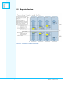
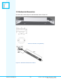
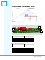
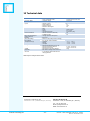
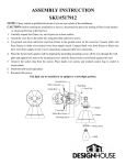
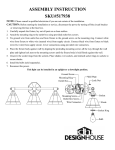
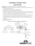
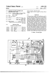
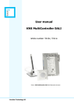
User’s Manual KNX MultiLight Dali (ML-D) Article number: 44002 Picture: KNX MultiLight products function Technology AS Table of Contents 1 THE KNX MULTILIGHT DALI ............................................................. 3 2 INTRODUCTION ................................................................................ 3 3 KNX MULTILIGHT DALI START-UP AND GENERAL FUNCTIONS ....... 5 4 GENERAL FUNCTIONS AND INTEGRATION WITH A USER PANEL .... 6 5 MOVEMENT AND LUX LEVEL DETECTION ......................................... 6 5.1 MOVEMENT SENSOR .......................................................................................................... 6 6 CONSTANT LIGHT CONTROLLER ....................................................... 8 6.1 CONSTANT LIGHT CONTROLLER OUTPUT ............................................................................. 8 6.2 MINIMUM DIMMING LEVEL AND TURN-OFF .......................................................................... 9 6.3 ACTIVATION OF CONSTANT LIGHT CONTROLLER .................................................................. 9 7 DALI ................................................................................................ 10 8 THERMOSTAT .................................................................................. 12 8.1 REGULATOR FUNCTIONALITY ............................................................................................ 12 8.2 OPERATIONAL MODES ...................................................................................................... 13 8.3 PARAMETERS ................................................................................................................... 13 8.4 LOCAL TEMPERATURE ADJUSTMENT .................................................................................. 16 8.5 REGULATOR FUNCTION .................................................................................................... 17 8.6 PI REGULATOR................................................................................................................ 18 9 LOGIC .............................................................................................. 20 9.1 PARAMETER .................................................................................................................... 20 10 BINARY INPUTS .............................................................................. 20 10.1 PARAMETER .................................................................................................................. 20 11 MECHANICAL DIMENSIONS............................................................ 23 11.1 DETECTION AREA MOVEMENT SENSOR (ML-M) .............................................................. 24 11.2 CONNECTOR PINOUT ..................................................................................................... 24 ................................................................................................................................................ 24 12 LAMP INTEGRATION AND WIRING DIAGRAM ............................... 25 12.1 DIAGRAM FOR DALI BROADCAST SINGLE EVG ............................................................... 25 12.2 DIAGRAM FOR DALI BROADCAST UPLIGHT AND DOWNLIGHT .......................................... 26 12.3 DIAGRAM FOR GROUP 0 AND 1 UPLIGHT AND DOWNLIGHT EVG ...................................... 26 13 TECHNICAL DATA ............................................................................ 27 function Technology AS -2- Manual – KNX MultiLight Dali Art.no. 44002 Doc.no. D-TS-ML-D-00 1 The KNX MultiLight Dali KNX MultiLight Dali is a room controller designed to be mounted inside lamps. The main functions of the KNX MultiLight Dali are: Controlling heating and cooling via KNX objects Controlling lighting through an embedded DALI master Local sensor input for movement, lux, temperature and user panel Digital input for pull-cord For programming and configuration: see chapters 3 to 10. For wiring and installation instructions: see chapter 12. For technical data: see chapter 13. 2 Introduction KNX MultiLight Dali is designed to be an efficient room controller system for office and commercial buildings. The core of the KNX MultiLight Dali is a demand controlled twostep temperature regulator for separate cooling- and heating control, temperature sensor and movement sensor. The functionality of the product can be configured and connected to the rest of the KNX automation system by using the ETS Engineering Tool Software (see www.knx.org) Example 1 – Heating regulator: The KNX MultiLight Dali can be configured as a two-step heating regulator. The regulator has one temperature set-point for a room that is occupied, and another temperature setpoint for a room that is vacant. Let us say the temperature set-point for an occupied room is 22°C, and the set-point for the vacant room is set to 19°C. The movement detector mounted in the lamp will detect a person walking into the room. The set-point will be raised from 19°C in standby mode (vacant) to 22°C in comfort mode (occupied). The thermostat output can be linked to external actuators for electrical heat cables, thermo shunts, fan-coils and other KNX products. Example 2 – Lighting: The KNX MultiLight Dali can control luminaires through the DALI light control interface based on daylight. So, when a person walks into the room and the temperature set-point is changed from standby to comfort mode, the light will also be turned on and the constant light regulator will keep the light level at the configured lux-level. The set-point for the constant light regulator can either be changed by parameters with the ETS Tool Software or by switch and dim objects (digital input from the pull-cord or other KNX switches). The MultiLight will learn the new lux-setpoint and control the light accordingly. function Technology AS -3- Manual – KNX MultiLight Dali Art.no. 44002 Doc.no. D-TS-ML-D-00 Example 3 – Ventilation: The KNX MultiLight Dali can control ventilation by KNX objects for the office space based on the movement detector and the temperature regulator. The ventilation can be reduced to a minimum when the room is vacant and the controller is in standby mode. The ventilation system will be asked to increase the ventilation when a person enters the room. The ventilation system will usually have a cooling effect for the room because of lower air temperature in the supplied air. The cooling regulator of the KNX MultiLight can trigger the need for extra ventilation based on the room temperature. Figure 1 - KNX MultiLight Dali user panel function Technology AS -4- Manual – KNX MultiLight Dali Art.no. 44002 Doc.no. D-TS-ML-D-00 3 KNX MultiLight Dali start-up and general functions KNX MultiLight Dali can be configured by using the ETS Tool Software. The product database file for KNX MultiLight Dali can be downloaded from http://www.functiontechnology.com/MultiLight. Documentation for the parameters, objects and example configurations can be found in the chapters below. The MultiLight can be set in programming mode either by pressing the programming button on the MultiLight unit, or by pressing the switch behind the movement sensor lens. See Figure 2 for the different ways to enter programming mode. Use a small circular object like a paper clip or a bare KNX copper wire to reach the programming button on the movement sensor. Figure 2 - Programming mode buttons The red programming LED on the control panel and behind the movement sensor lens will be lit when the KNX MultiLight is in programming mode. The programming LED will blink when the MultiLight is not programmed (un-programmed node). The node will check communication with movement detector, temperature sensor and DALI interface. If communication has failed, the object “Device self-test status” will be set to “1”. When the error situation is cleared, the “Device self-test status” object changes its value to “0”. The start-up functionality for a unit that has not been programmed with ETS includes: 1. Walk-in test for motion detection with the red LED behind the motion sensor lens 2. Binary input will have switch and dim functionality for the connected DALI lamps Note: The KNX node includes basic functionality listed above for test and commissioning purposes that will be removed after the first ETS download. function Technology AS -5- Manual – KNX MultiLight Dali Art.no. 44002 Doc.no. D-TS-ML-D-00 4 General functions and integration with a user panel The status of the KNX MultiLight is shown by the object “Self-Test status”. For normal operational nodes this status object is low. If the Dali interface, movement- or temperature sensor does not respond, the “Self-Test status” is set high. The object can be configured to be sent cyclically [1 to 24 hours]. Figure 3 – General parameter window The KNX MultiLight can be configured with or without motion- and temperature sensors. The temperature regulator can still be activated based on external temperature object even without a temperature sensor connected to the unit (see Figure 3). PIR sensitivity can be adjusted from 20 to 100, where 20 is the highest sensitivity. This parameter is set to 30 by default, and should not be set lower than this value without testing for false detection. 5 Movement and LUX level detection 5.1 Movement sensor The combined movement and LUX level (brightness) sensor is connected to the MultiLight Dali KNX node through an 8-wire cable. The parameter “Activation of local movement” in the General tab has to be enabled before the movement channel parameter windows appear. There are 4 channels available based on the movement detector. Each channel can be configured with recovery time, cyclic sending and configuration for start and end of detection. There is also an object for blocking the movement channel, and the option to send a value at start and/or end of detection. function Technology AS -6- Manual – KNX MultiLight Dali Art.no. 44002 Doc.no. D-TS-ML-D-00 Figure 4 - Movement sensor parameter window The movement channels can be configured individually with: 1. Recovery time for detection from 1 to 255 minutes. The recovery time specifies the time between the last detected movement and when the object is set low. 2. Cyclic sending ON commands of "Movement chX: Switch” object can be enabled or disabled. The cycle time can be between 1 and 255 minutes. 0 disables the function. 3. Reaction start of detection 4. Reaction end of detection 5. Enable or disable movement blocking object (see object description) 6. Transmit value for start and end of detection (enables a movement value) 7. Movement Ch 1 can be configured as a master (i.e. the write flag is enabled for the switch object) The lux measurement from the movement sensor is read-enabled as object 41 “Const.Light Controller: Current value (lux)”. Movement Ch1 switch object can be triggered by communication objects, as well as the local movement sensor, when the “Master function for switch object” is enabled. 5.1.1 Cyclic sending If the value of cyclic sending is lower than the recovery time, the sensor will not send any cyclic ON telegrams. If the two values are the same, the sensor sends one cyclic sending right before the recovery time elapses. The cyclic sending time will not be affected by a re-trigged recovery time. function Technology AS -7- Manual – KNX MultiLight Dali Art.no. 44002 Doc.no. D-TS-ML-D-00 6 Constant light controller The constant light controller will use the LUX level measurement from the movement sensor and will control the dimming value of the lamps either by output object or the internal DALI interface. The constant light controller will change the dimming value based on the “step size in %” and “step size in seconds” parameters. The default value of 3% dim value change in 5 seconds should fit most lighting systems. If long delay is expected from dim value update to actual change in light level, then lower the step size in % and increase the step size in seconds. 6.1 Constant light controller output The output will not change as long as the current lux level is within the “input hysteresis for constant light control” which is default at 50 lux. This means that the output will be changed + or – 3% if the measured value is lower than 650 lux or higher than 750 lux for a set-point of 700 lux. The output from the constant light regulator can be set via parameter to: - Communication object (“By object”) - DALI interface group 0 (“DALI Group 0”) - DALI interface group 0 and 1 (“DALI Group 0 and 1”) - DALI interface Broadcast (“DALI Broadcast”) If the output of the constant light controller is configured as “By object”, then the DALI groups that should be constant light controlled must be linked manually by group addresses. If the output of the constant light controller is configured as “DALI Broadcast”, then all connected DALI lamps will follow the output value from the constant light controller. 6.1.1 Output with offset Two objects appear when the constant light controller output type “By object” is selected; the output value object and the output value with offset object. The output value with offset can control a group of lamps with a 0 to 50% higher dimming value than the main group of lamps. Typically, the main group of lamps would be closest to the façade, and the group of lamps controlled with the output value with offset would be the lamps farthest away from the façade. The option to have an offset between two DALI groups is also possible when “Dali Group 0 and 1” is the chosen output from the constant light controller. Typically, in a classroom the row of lights closest to the windows (DALI Group 0) will be dimmed down, and the row of lamps farthest away from the windows (DALI Group 1) will have a higher dimming value based on the offset parameter. function Technology AS -8- Manual – KNX MultiLight Dali Art.no. 44002 Doc.no. D-TS-ML-D-00 6.2 Minimum dimming level and turn-off The minimum dimming level can be set to a value in percent to prevent low dimming values. The parameter “Standby/minimum level for controller in %” will both act as this minimum dimming level as well as the standby dim level after the presence object (or internal sensor) has been switched off. The parameter “Time in standby and delay before turning off light” will determine when the lamp will be turned off. It can be unpleasant for the user of a room to experience constant light control where the lamp is turned off completely. It is therefore possible to set both minimum dimming level, time delay at minimum level and disabling of turn-off from the constant light regulator. 6.3 Activation of constant light controller The constant light controller can be activated either by communication object or by “Movement Ch 1” (settable via the parameter “Presence activation of controller”). The controller can be disabled by linking one or more of the three disable objects (object 44-46). The constant light controller will be disabled until the presence activation is set to false, either by object or by movement ch 1. It is possible to re-configure the disable objects to work as set-point changers. When the “Local lux adjustment by dimming or value” parameter is set, object 44-45 will adjust the light level either by dimming or by value and make the constant light regulator learn the new lux level. The new level will be stored until the device has lost bus power. Figure 5 – Constant light controller parameter window function Technology AS -9- Manual – KNX MultiLight Dali Art.no. 44002 Doc.no. D-TS-ML-D-00 6.3.1 LUX calibration The lux level object, “Const.Light Controller: Current value (lux)”, can be calibrated by writing to the object. The raw lux value will be subtracted from the written value and stored permanently in EEPROM/flash. Both raw values and the resulting calibrated values are shown in Figure 6. The pink line is the raw value (V) from the sensor, the blue line is the wanted value (W) set by the user. The calibration factor is: C=1-(V-W)/V = W/V If the raw value V=1000, and the object is updated with 800, then the calibration factor will be: c=1-(1000-800)/1000=0.8. See the graph in Figure 6. The formula for calculating the lux is: Lux=c*V Figure 6 - Raw and calibrated lux values The calibration factor is set to 1 and the raw value is used if “0” is written to the “Current value (lux)” object. The object should be set to 0 to clear the current calibration before re-calibrating the lux level. The lux level calibration is limited to 2 times the raw lux level, so the calibration is limited to 2000 if the raw lux level is 1000. 7 DALI The KNX MultiLight has a built-in DALI gateway that uses DALI broadcast can be commands to control the lamps. The benefit of broadcast-mode is that there is no need for addressing the individual DALI lamps. It is possible to use up to four DALI groups (group 0 to 3) for individual control. The DALI lamps must be assigned to group 0 to 3 with an external DALI programming interface in order to use the group addressing mode. function Technology AS - 10 - Manual – KNX MultiLight Dali Art.no. 44002 Doc.no. D-TS-ML-D-00 Figure 7 – DALI interface parameters The DALI interface can be configured with start-up dimming value, switch on/off permissions, dimming time, minimum- and maximum dimming values. function Technology AS - 11 - Manual – KNX MultiLight Dali Art.no. 44002 Doc.no. D-TS-ML-D-00 8 Thermostat 8.1 Regulator functionality The thermostat can control both heating- and cooling systems either by automatic switching between heating and cooling mode, or controlled by object. The regulator outputs can be configured either as ON/OFF control or continuous (0-100%) based on a PI regulator. Regulator capability: Four modes of operation: comfort, standby, night and frost/heat protection On/off or 0-100% control for heating and cooling system Combined heating- and cooling regulator with automatic or manual switch-over Additional heating or cooling stage with on/off control Automatic transmission of the regulator outputs on change or cyclic every 40. Minutes. Room temperature measurement from the user panel or movement sensor The temperature sensor can be calibrated (+/- 12.6K) in steps of 0.1 K with ETS parameter The temperature sensor can be internal calibrated (+/-1.5K) from the user panel The actual temperature and the set-point temperature can be sent to the bus on change or cyclically Feedback from the regulator if heating or cooling mode is active Set-point values: The base temperature set-point is defined in parameter (“Base setpoint in ºC”) and is shown by object “Thermostat – Base setpoint”. This object can also be configured for write access (selectable to be stored in permanent memory or not) The working regulator set-point is shown by the object “Thermostat – Actual setpoint”. The base setpoint is only settable to whole degrees (eg. 21 or 22 °C) Parameters for heating and cooling temperature set-points for standby and night mode Set-points for the additional heating/cooling stage are derived from the values from the basic stage with an additional stage offset Setpoint value shifting (local adjustment +/-3K) by local operation on the user panel or by object. The step size is 0.5K The reduced or increased temperatures for standby and night mode are settable in steps of 0.1K Frost/heat protection: frost protection set to 10 ºC (not adjustable) and heat protection set to 35 ºC (not adjustable) function Technology AS - 12 - Manual – KNX MultiLight Dali Art.no. 44002 Doc.no. D-TS-ML-D-00 8.2 Operational modes The KNX MultiLight has 4 operational modes; Comfort, Stand-by, Night and Frost/heat protection. The active mode is either selected based on the three 1.bit objects "Comfort Mode", "Night Mode" and "Frost/heat protect" or based on the “Thermostat: Operation mode HVAC”. The table below shows which mode is active based on the status of these three objects (X = don’t care). Table 1 – Resulting regulator modes Comfort Mode Standby Night Mode Frost/heat protect 8.3 Comfort Mode (obj. 9) 1 0 0 X Night Mode (obj. 10) X 0 1 X Frost/ heat (obj. 11) 0 0 0 1 Operation mode object value (obj. 12) 1 2 3 4 Parameters 8.3.1 Comfort mode The thermostat is using the “Base setpoint in ºC” as the regulator set-point for the heating regulator in comfort mode. The heating regulator starts to heat if the actual temperature falls below the base setpoint minus the parameter value for “Low hysteresis in 0.1K". The heating regulator will turn off the heat when the actual temperature rises above the base setpoint. The regulator will turn off the heat at 21.0 ºC with the parameter settings shown in Figure 8 The cooling system will turn on at the temperature "Base setpoint in ºC" + "Deadzone between heating and cooling in 0.1K" + "High hysteresis in 0.1K". The cooling system will be turned off when the temperature falls below the base set-point + deadzone. The cooling system will be turned off at 21.0 + 2.0 = 23ºC with the parameter settings shown Figure 8. Figure 8 - Thermostat settings function Technology AS - 13 - Manual – KNX MultiLight Dali Art.no. 44002 Doc.no. D-TS-ML-D-00 It is the value from the object "Actual setpoint" that the regulator uses as the temperature set-point. The “Actual setpoint” will change depending on the “Base setpoint”, the active mode, if the regulator is in heating- or cooling mode and the local temperature adjustment. 8.3.2 Standby mode The regulator goes to standby mode if the three communication objects "Comfort Mode", "Night Mode" and "Frost/heat protect" are low. The "Actual setpoint" in this mode will be set to "Base setpoint" + "Reduced Heating in standby mode". The "Actual setpoint" is set to: 21ºC + (-1.0ºC) = 20ºC for the parameter settings shown in Figure 8. For the cooling system in standby mode the "Actual setpoint" is set 1 degree higher than in comfort mode: 21ºC + 2ºC + 1ºC = 24ºC The user panel LED indication for the local temperature adjustment will be turned off when the regulator goes into standby mode. The LED indication for the active heating- and cooling system will still be active. 8.3.3 Night mode The regulator will go to night mode if only the “Night Mode” object is set high. The temperature setpoint for the heating and cooling systems will change according to the parameters "Reduced Heating in Night mode" and "Increased cooling in Night mode". For the heating system the “Actual setpoint” is set to: 21ºC + (-3.0ºC) = 18ºC with the parameters shown in Figure 8. For the cooling system the "Actual setpoint" will be: 21ºC + 2ºC + 3ºC = 26ºC The user panel LED indication for the local temperature adjustment will be turned off when the regulator goes into night mode. The LED indication for the active heating- and cooling system will still be active. 8.3.4 Frost/Heat protection The Frost/Heat protection regulator mode will set fixed temperature setpoints for the heating and cooling regulators. The heating system is turned on if the temperature falls below 10ºC – 0.5ºC hysteresis. The heating system is turned off if the temperature goes above 10ºC. The cooling system will turn on if the temperature goes above 35ºC + 0.5ºC hysteresis and will turn off again when the temperature goes below 35ºC. The user panel LED indication for the local temperature adjustment will be turned off when the regulator goes into Frost/heat protection mode. The LED indication for the heating- and cooling system alternates between heating and cooling every second. function Technology AS - 14 - Manual – KNX MultiLight Dali Art.no. 44002 Doc.no. D-TS-ML-D-00 8.3.5 Basic heating and cooling stage See the description of the different regulator modes in chapters 8.3.1 to 8.3.4. 8.3.6 Additional heating and cooling stage The KNX MultiLight can control an additional heating and/or cooling system with ON/OFF control. The temperature limits for the additional heating- and cooling systems can be defined by parameters, see Figure 9 and Figure 10. The additional heating stage will be turned on if the room temperature has dropped 2ºC below the parameter settings in the thermostat parameter window, see Figure 8. The hysteresis for the additional heating stage is fixed to +0.5ºC. The additional heating stage will turn on if the temperature falls below 21ºC - 2.0ºC = 19ºC and turn off at 21ºC - 2.0ºC + 0.5ºC = 19.5ºC in comfort mode according to the parameter settings shown in Figure 8 and Figure 9. Figure 9 - Heating parameter windows Figure 10 - Cooling parameter windows The additional cooling stage will be turned on bases on the stage offset from basic to additional stage, see Figure 10. The additional stage cooling will turn on if the temperature rises above 23ºC + 2.0ºC = 25ºC for comfort mode (see parameters Figure 8). The additional stage will turn off at 23ºC + 2.0ºC - 0.5ºC = 24.5ºC function Technology AS - 15 - Manual – KNX MultiLight Dali Art.no. 44002 Doc.no. D-TS-ML-D-00 8.4 Local temperature adjustment The temperature set-point can be adjusted both by the communication object “Thermostat: Local adjustment of temp offset" (obj. 8) and by the user panel. The local adjustment object can adjust the actual temperature set-point by +/-10ºC. The user panel temperature adjustment can maximum be +/-3ºC. The adjustment done on the panel will update the local adjustment of temperature communication object. The heating system will be turn on at 20.5ºC - 3ºC = 17.5ºC and off at 18.0ºC in comfort mode with the parameters shown in Figure 8. The cooling system will be turned on at 21ºC - 3ºC + 2ºC + 0.5ºC = 20.5ºC and Off if the temperature drops below 20.0ºC. The temperature sensor includes a filtering algorithm that will eliminate temperature rise after the user panel has been touched. The temperature measurement will remain unchanged for 3 to 8 minutes after the buttons on the user panel has been operated. It is possible to limit the temperature adjustment up or down, for example to +3 to -1C, +1.5C to -0.5C and +0.5 to -0C. The LED indicating +3 to -3 on the user panel will still show the full scale, so the user will not notice the limitation. If the panel is removed, all regulator outputs will be set to “0” one time, and the actual temperature is send 0ºC. The “Self test” object will indicate the error and will be transmitted as “1”. function Technology AS - 16 - Manual – KNX MultiLight Dali Art.no. 44002 Doc.no. D-TS-ML-D-00 8.5 Regulator function Figure 11 - Asymmetric regulator functionality function Technology AS - 17 - Manual – KNX MultiLight Dali Art.no. 44002 Doc.no. D-TS-ML-D-00 8.6 PI Regulator The KNX MultiLight thermostat can control heating and cooling systems with Pulse-WithModulation. The communication object for the PWM control value output is a 1.byte 0100% of the type DPT5.001. The control value will automatically be transmitted every 40 minutes and can also be transmitted when the value has changed a specific percentage, see Figure 12. Figure 12 - Heating PI-regulator The PI-regulator is configured with a proportional factor (K p) and a reset time (Ti). The equation for the regulator output is shown in (3). The integration of the error for each regulator evaluation is substituted by the step number (30 second increments) multiplied with the last error function: e(n)∙n divided by the time constant, see equation (3) The proportional factor Kp : KP 1 (1) proportional _ range The error function e(n): e(n) = set_point - actual_temperature (2) The regulator output equation: e(n) n n u (n) K P e(n) K P e(n) 1 (3) 2 TI 2 TI function Technology AS - 18 - Manual – KNX MultiLight Dali Art.no. 44002 Doc.no. D-TS-ML-D-00 Example: The regulator function (3) is evaluated every half minute with the parameters for Electric heating (4K/100min) and a constant error function of e(n)=set_pointactual_temp=23-21=2. The calculated output is shown in equation (4), where n is the number of half minute intervals: u ( n) 1 n (4) (23 21) 1 4 2 100 The graph for the regulator output is shown in Figure 13. The time factor, n, will be set to 0 when the error function, e(n) becomes 0 or less. The regulator output is capped to maximum 1.0, which is equivalent to 100% for the control value communication object. Regulator output (Kp=0.25, Ti=100, e(n)=2) Regulator output 1,2 1 0,8 0,6 Serie1 0,4 0,2 0 1 21 41 61 81 Time(min) 101 121 Figure 13 - Regulator output for constant e(n)=2 function Technology AS - 19 - Manual – KNX MultiLight Dali Art.no. 44002 Doc.no. D-TS-ML-D-00 9 Logic The KNX MultiLight includes three logic functions: Logic AND/OR, 1 byte comparator and timer function. 9.1 Parameter Figure 14 – Parameters for the logic module 9.1.1 Logic AND/OR The logic function AND or OR can be enabled by parameter. The output object will be updated based on the state for the two inputs. 9.1.2 Comparator The one byte comparator will update the output object with a value based on the chosen parameter function (highest, lowest or average) and the last value for the two input objects. 9.1.3 Timer function The timer works as a staircase function with a reset time both settable in parameters (in minutes) and also changeable via communication object. When the “Staircase timer logic: In/out” is set, the timer will start and the object will be set to false after the timer duration has elapsed. 10 Binary inputs 10.1 Parameter KNX MultiLight has one digital input that can be used as a simple switch, dimming switch or shutter control switch. The simple switch can be either configured as on, off or toggle. Detection of short and long switch operation will be determined for dimming- and shutter switch. 10.1.1 Switch Switch functionality where the object is high or low depending on the detection of rising or falling edge for the input. function Technology AS - 20 - Manual – KNX MultiLight Dali Art.no. 44002 Doc.no. D-TS-ML-D-00 Parameter choices for the Switch-function: Rising edge – On Rising edge – Off Rising edge – Toggle Rising edge – On, Falling edge – Off Rising edge – Off, Falling edge – On 10.1.2 Dimming Light dimming functionality with one communication object for "Short operation – Switch” and one for "Long operation - dimming". Parameter choices for the dimming-function: Reaction short operation: "Off", "On" or "Toggle" Reaction long operation: "Dim darker", "Dim brighter" or "Dim brighter /darker" Please note that the action for long operation is locked to “Toggle” if the reaction for short operation is “Toggle” function Technology AS - 21 - Manual – KNX MultiLight Dali Art.no. 44002 Doc.no. D-TS-ML-D-00 10.1.3 Shutter Shutter control with one object for "Short operation - stop/step" and one object for "Long operation - up/down". Parameter choices for the shutter control: Reaction short operation: "Stop/up", "Stop/down" or "Stop/toggle up/down" Reaction long operation: "Up", "Down" or "Toggle up/down" Please note that the action for long operation is locked to "Toggle up/down" if the reaction for short operation is "Stop/toggle up/down". function Technology AS - 22 - Manual – KNX MultiLight Dali Art.no. 44002 Doc.no. D-TS-ML-D-00 11 Mechanical dimensions The KNX node is shown Figure 15 and Movement sensor in Figure 16. Figure 15 - Mechanical dimensions of ML-K in mm (HxWxL: 22 x W 30 x L 185) Figure 16 - Mechanical dimensions of ML-M in mm (Ø31x21) Figure 17- Mechanical dimensions of ML-P function Technology AS - 23 - Manual – KNX MultiLight Dali Art.no. 44002 Doc.no. D-TS-ML-D-00 11.1 Detection area movement sensor (ML-M) 11.2 Connector pinout J1 J2 J5 J4 Table 2 – 6p Wago connector for mains, DALI and digital input (J2) Signal Line Neutral Digital input signal Digital input common DALI DALI + Pin number 1 2 3 4 5 6 Table 3 – 2pin Wago connector (J1) Signal KNX KNX + Pin number 1 2 Table 4 – 4pin Molex connector (two paralel connectors J4 and J5) Signal +3.7V 0-V Com +20V function Technology AS Pin number 1 2 3 4 - 24 - Manual – KNX MultiLight Dali Art.no. 44002 Doc.no. D-TS-ML-D-00 12 Lamp integration and wiring diagram The KNX MultiLight Dali is designed to fit inside ceiling suspended fluorescent light fixtures with one to four EVGs. Typical wiring configurations are shown in chapter 12.1 and 12.3. The EVGs can be of any DALI enabled type, usually ranging from single 35W to double 80W outputs, with DA+ and DA- connection. Examples EVGs: Philips HF-R TD 214-35 TL5, Osram QTi DALI 2x35/49/80 DIM, Tridonic PCA Excite and ECO series. Wire size from 0.5 to 1.5 mm2 can be connected to the quick connect terminals of the KNX MultiLight. Remove 9-10 mm of the wire insulation. 12.1 Diagram for DALI Broadcast single EVG L N L N DA + DA - PE KNX + KNX - KNX Cable/ double insulated L N Inp.1 COM DA DA + KNX - Black + Red Local sensor Pull-switch User panel function Technology AS - 25 - Manual – KNX MultiLight Dali Art.no. 44002 Doc.no. D-TS-ML-D-00 12.2 Diagram for DALI Broadcast uplight and downlight LL NN EVG EVG22 DALI DALIBROADCAST BROADCAST DA DA++ DA DA- LL NN L L N N EVG EVG11 DALI DALIBROADCAST BROADCAST DA DA++ DA DA- - PE PE KNX + KNX + KNX KNX - KNX KNXCable/ Cable/double doubleinsulated insulated LL NN Inp.1 Inp.1 COM COM DA DA- DA DA++ Pull-switch Pull-switch - Black KNX Red KNX +- +Black Red Local Local sensor sensor Userpanel panel User 12.3 Diagram for group 0 and 1 uplight and downlight EVG IFIFBALLAST BALLASTNOT NOTADRESSED ADRESSEDFROM FROM FACTORY, FACTORY,TERMINAL TERMINALFOR FORDALI DALITOOL TOOL NEEDED NEEDEDFOR FORSYSTEM SYSTEMINTEGRATOR INTEGRATOR LL NN EVG EVG22UPLIGHT UPLIGHT DALI DALIGROUP GROUPNO NO"1" "1" DA DA++ DA DA- - DA + DA + DA DA - LL NN L L N N EVG EVG11DOWNLIGHT DOWNLIGHT DALI DALIGROUP GROUPNO NO"0" "0" DA DA++ DA DA- - PE PE KNX + KNX + KNX KNX - KNX KNXCable/ Cable/double doubleinsulated insulated LL NN Inp.1 Inp.1 COM COM DA DA- DA DA++ Pull-switch Pull-switch - Black KNX Red KNX +- +Black Red Local Local sensor sensor Userpanel panel User function Technology AS - 26 - Manual – KNX MultiLight Dali Art.no. 44002 Doc.no. D-TS-ML-D-00 13 Technical data Power KNX Power AC Mains Inputs Connections Movement detector EIB / KNX operating and display elements Housing EIB / KNX voltage DALI voltage Temperature range Design Weight Approvals CE mark - Operating voltage, KNX Power consumption, KNX Operating voltage Power consumption (standby) Number of inputs Polling voltage Un Sensing current In Maximum cable lengths KNX Inputs Wiring Connection of sensor Detector area at floor (diameter) Installation height Through separate control panel - IP20, PVC SELV 29 V DC (safety extra low voltage) ELV 16V DC (basic insulation) Operation Storage Transport Dimensions KNX Node (H x W x D) Dimension Movement detector Dimension User panel KNX node and movement detector EIB / KNX according to EN 50 090-2-2 In accordance with the EMC and low voltage guidelines. 21...30 V DC, Normally 10mA, Peak 17mA 230V 50Hz 0.5VA 1 3V 1mA 2m Quick connect Quick connect 2 0,5-1,5 mm 4-pole micro plug 4m 2m – 5 °C ... + 55 °C – 25 °C ... + 65°C – 25 °C ... + 65 °C 22 x 30 x 185 mm 21 mm x Ø=31 mm 154 mm x Ø=14 mm 400g Data subject to change without notice Producer: Distributor: Function Technology AS kanalveien 117b | N-5068 Bergen | Norway function Products AS kanalveien 117b | N-5059 Bergen | Norway Tel: +47 55 38 50 80 Email: [email protected] WEB: www.function.no function Technology AS - 27 - Manual – KNX MultiLight Dali Art.no. 44002 Doc.no. D-TS-ML-D-00