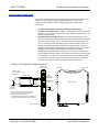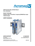
1
USB Programmable, DIN-Rail Mount, Thin Temperature Transmitter, Two-Wire Model TT233-0600, Isolated T/C & mV Input USER’S MANUAL ACROMAG INCORPORATED 30765 South Wixom Road Wixom, MI 48393-7037 U.S.A. Tel: (248) 295-0880 Fax: (248) 624-9234 email: [email protected] Copyright 2012-2013, Acromag, Inc., Printed in the USA. Data and specifications are subject to change without notice. 8500-934C Model TT233-0600 Two-Wire Thermocouple/mV Transmitter w/USB Table of Contents GETTING STARTED DESCRIPTION ....................................................................................................... 4 Key Features ........................................................................................................................4 Application ..........................................................................................................................4 Mechanical Dimensions .......................................................................................................5 DIN Rail Mounting & Removal ..............................................................................................5 ELECTRICAL CONNECTIONS ............................................................................ 6 Sensor Input Connections ....................................................................................................7 Output/Power Connections .................................................................................................8 Earth Ground Connections ................................................................................................. 10 USB Connections................................................................................................................ 11 CONFIGURATION SOFTWARE ...................................................................... 12 Quick Overview ................................................................................................................. 12 TECHNICAL REFERENCE OPERATION STEP-BY-STEP .......................................................................... 14 Connections....................................................................................................................... 14 Configuration..................................................................................................................... 16 Calibration ......................................................................................................................... 20 Input Calibration ......................................................................................................................... 21 Output Calibration ...................................................................................................................... 21 TRef Calibration........................................................................................................................... 22 Restore Factory Calibration ........................................................................................................ 22 Other Configuration Controls ............................................................................................. 22 BLOCK DIAGRAM ............................................................................................. 24 How It Works ..................................................................................................................... 24 Acromag, Inc. Tel: 248-295-0880 -2- -2http://www.acromag.com http://www.acromag.com Model TT233-0600 Two-Wire Thermocouple/mV Transmitter w/USB TROUBLESHOOTING ....................................................................................... 25 Diagnostics Table ............................................................................................................... 25 Service & Repair Assistance ............................................................................................... 27 ACCESSORIES .................................................................................................... 28 Software Interface Package................................................................................................ 28 USB Isolator ....................................................................................................................... 28 USB A-B Cable .................................................................................................................... 28 USB A-mini B Cable ............................................................................................................ 28 SPECIFICATIONS .............................................................................................. 29 Model Number .................................................................................................................. 29 Input ................................................................................................................................. 29 Output............................................................................................................................... 31 USB Interface ..................................................................................................................... 32 Enclosure & Physical .......................................................................................................... 33 Environmental ................................................................................................................... 33 Agency Approvals .............................................................................................................. 34 Reliability Prediction .......................................................................................................... 34 Configuration Controls ....................................................................................................... 34 REVISION HISTORY ......................................................................................... 35 All trademarks are the property of their respective owners. IMPORTANT SAFETY CONSIDERATIONS You must consider the possible negative effects of power, wiring, component, sensor, or software failure in the design of any type of control or monitoring system. This is very important where property loss or human life is involved. It is important that you perform satisfactory overall system design and it is agreed between you and Acromag, that this is your responsibility. The information of this manual may change without notice. Acromag makes no warranty of any kind with regard to this material, including, but not limited to, the implied warranties of merchantability and fitness for a particular purpose. Further, Acromag assumes no responsibility for any errors that may appear in this manual and makes no commitment to update, or keep current, the information contained in this manual. No part of this manual may be copied or reproduced in any form without the prior written consent of Acromag, Inc. For additional information on these devices and related topics, please visit our web site at www.acromag.com and download our whitepaper 8500-904, Introduction to Two-Wire Transmitters. Also see 8500-926, Minimizing Error in Thermocouple Transmitter Connections. Acromag, Inc. Tel: 248-295-0880 -3- -3http://www.acromag.com http://www.acromag.com Model TT233-0600 Two-Wire Thermocouple/mV Transmitter w/USB GETTING STARTED DESCRIPTION Symbols on equipment: ! Means “Refer to User’s Manual (this manual) for additional information”. The TT233-0600 is an ANSI/ISA Type II transmitter designed to interface with a thermocouple sensor (Type J, K, T, R. S, B, E, N), or millivoltage (±100mV) input source, isolate the input signal, and modulate a 4-20mA current signal to drive a two-wire current loop. This unit is setup and calibrated using configuration software and a USB connection to Windows-based PC’s (Windows XP and later versions only). The unit provides an adjustable input range, degrees F or C selection, T/C linearization, input isolation, break detection, variable input filter, and cold-junction compensation. Key Features Digitally setup and calibrated w/ Windows software via USB. Thin 12.5mm wide enclosure for high-density DIN-rail mounting. High measurement accuracy and linearity. T/C Type J, K, T, R, S, B, E, N, or ±100mV input support. T/C inputs are linearized with respect to temperature. T/C inputs include accurate Cold Junction Compensation. Supports both Celsius and Fahrenheit temperature units. Adjustable input ranges. Extra output connections support Sink or Source output wiring. Variable Input Filter Adjustment. Normal or Reverse Acting output. Up-scale or down-scale lead-break/burnout detection. Convenient non-polarized two-wire current loop powered. Namur compliant loop current. Wide ambient temperature operation. Hardened For Harsh Environments. CE Approved. UL/cUL Class 1, Division 2 Approved. Application This transmitter is designed for high-density mounting on 35mm T-type DIN rails. This model isolates its input signal and can mate with grounded or non-grounded thermocouples. It provides an output current linearized to the T/C sensor temperature. Optionally, it supports a ±100mV input range and will drive an output current linear to the sensor millivoltage. The output signal is transmitted via a two-wire, 4-20mA current loop. Two-wire current signals can be transmitted over long distances with high noise immunity. Sensor lead-break detection and the inherent 4mA live-zero output offers convenient I/O fault detection, should an input or output wire break. Extra connections at the output allow it to be optionally wired for a “sourced” 4-20mA output configuration (see Output/Power Connections). Acromag, Inc. Tel: 248-295-0880 -4- -4http://www.acromag.com http://www.acromag.com Model TT233-0600 Two-Wire Thermocouple/mV Transmitter w/USB Mechanical Dimensions 99.0 (3.90) Units may be mounted to 35mm “T” type DIN rail (35mm, type EN50022), and side-by-side on 0.5inch centers. WARNING: IEC Safety Standards may require that this device be mounted within an approved metal enclosure or sub-system, particularly for applications with exposure to voltages greater than or equal to 75VDC or 50VAC. 12.5 (0.50) 114.5 (4.51) DIMENSIONS ARE IN MILLIMETERS (INCHES) DIN Rail Mounting & Removal Refer to the following figure for attaching and removing a unit from the DIN rail. A spring loaded DIN clip is located on the input side bottom. The opposite rounded edge at the bottom of the output side allows you to tilt the unit upward to lift it from the rail while prying the spring clip back with a screwdriver. To attach the module to T-type DIN rail, angle the top of the unit towards the rail and place the top groove of the module over the upper lip of the DIN rail. Firmly push the unit downward towards the rail until it snaps into place. To remove it from the DIN rail, first separate the input terminal blocks from the bottom side of the module to create a clearance to the DIN mounting area. You can use a screwdriver to pry the pluggable terminals out of their sockets. Next, while holding the module in place from above, insert a screwdriver into the lower path of the bottom of the module to the DIN rail clip and use it as a lever to force the DIN rail spring clip down while pulling the bottom of the module outward until it disengages from the rail. Then simply lift it from the rail. Acromag, Inc. Tel: 248-295-0880 -5- -5http://www.acromag.com http://www.acromag.com Model TT233-0600 Two-Wire Thermocouple/mV Transmitter w/USB TT2XX MODULE DIN RAIL MOUNTING AND REMOVAL TILT MODULE UPWARD TOWARDS RAIL AND HOOK ONTO UPPER LIP OF RAIL. ROTATE MODULE DOWNWARD TO ENGAGE SPRING CLIP ONTO LOWER LIP OF RAIL. (OUTPUT SIDE) TOP 35mm DIN Rail TT2XX MODULE T-Rail SPRING CLIP BOTTOM (INPUT SIDE) SCREWDRIVER SLOT FOR REMOVAL FROM "T" TYPE DIN RAIL USE SCREWDRIVER TO REMOVE MODULE FROM RAIL AS SHOWN ELECTRICAL CONNECTIONS ! WARNING – EXPLOSION HAZARD – Do not disconnect equipment unless power has been removed or the area is known to be non-hazardous. WARNING – EXPLOSION HAZARD – Substitution of any components may impair suitability for Class I, Division 2. WARNING – EXPLOSION HAZARD – The area must be known to be non-hazardous before servicing/replacing the unit and before installing. Wire terminals can accommodate 14-26 AWG solid or stranded wire. Input wiring may be shielded or unshielded type. Ideally, output wires should be shielded twisted pair. Terminals are pluggable and can be removed from their sockets by prying outward from the top with a screwdriver blade. This model includes optional input cable shield and earth ground termination points at TB2, just below input terminal block TB1. Strip back wire insulation 0.25-inch on each lead and insert the wire ends into the cage clamp connector of the terminal block. Use a screwdriver to tighten the screw by turning it in a clockwise direction to secure the wire (0.50.6Nm torque). Since common mode voltages can exist on signal wiring, adequate wire insulation should be used and proper wiring practices followed. As a rule, output wires are normally separated from input wiring for safety, as well as for low noise pickup. Acromag, Inc. Tel: 248-295-0880 -6- -6http://www.acromag.com http://www.acromag.com Model TT233-0600 Two-Wire Thermocouple/mV Transmitter w/USB Sensor Input Connections Sensor wires are wired directly to transmitter input terminals at the bottom of the module, or the left side (the spring-loaded DIN clip side), as shown in the connection drawing below. Observe proper polarity when making input connections. Transmitter Input signal is isolated from the output/power signal. T/C inputs use input terminals “+” and “-“. The positive input is on the left and labeled “+”, and the negative input is to its right. Observe proper polarity. See connection figure below. Input Cable Shield Terminals “G” and “S” – For best performance, you can connect an input cable shield and earth ground at terminal block TB2 just below the input terminals of TB1. The “G” terminal is for connecting earth ground. The “S” terminal is used for terminating an input cable shield or its drain wire. The use of shielded input cable terminated in this way will help to improve transient input protection and minimize noise in noisy environments. DO NOT CONNECT TO THE SHIELD CONNECTIONS IF YOUR SHIELD IS ALREADY GROUNDED AT THE OTHER END. Internally, the “S” terminal connects to one end of a 3300pF isolation capacitor whose other end connects to the G terminal for earth ground. The Earth ground connection here is fully isolated from the rest of the internal circuit. Input circuit common also shunts to this ground terminal via an isolation capacitor for improved transient protection. MODEL TT233-0600 INPUT SENSOR WIRING BOTTOM VIEW (INPUT SIDE) INPUT SIDE THERMOCOUPLE TYPE J, K, T, E, R, S, B, OR N OUTPUT SIDE TB1 OR MILLIVOLT SHIELDED CABLE INPUT +/- + 1 2 3 4 - INPUT TERMINALS (UPPER LEVEL) 2 - S SHIELD 4 OPTIONAL EARTH GROUND (SEE NOTE 1) 1 + OPTIONAL SHIELD GROUND TB2 G S SHIELD/GROUND TERMINALS MODEL TT233-0600 G 3 CONNECT EARTH GROUND HERE NOTE 1: DO NOT GROUND THE INPUT SENSOR IF UNIT IS CONNECTED TO A GROUNDED PC WITHOUT USING A USB ISOLATOR. THE EARTH GROUND CONNECTION AT TERMINAL 3 IS ISOLATED FROM THE INPUT AND OUTPUT CIRCUITS. DIN RAIL SPRING CLIP DIN RAIL SPRING CLIP Acromag, Inc. Tel: 248-295-0880 -7- -7http://www.acromag.com http://www.acromag.com Model TT233-0600 Two-Wire Thermocouple/mV Transmitter w/USB Output/Power Connections This transmitter has an ANSI/ISA Type 2 output in which the unit’s power and output signal share the same two leads, and the transmitter output has a floating connection with respect to earth ground. Connect a DC power supply and load in series in the two-wire loop as shown below. Output connections are not polarized. The output + and – designations are for reference only with current input to Output+ and returned via Output- (current sinking). Loop supply voltage should be from 12-32V DC with the minimum voltage level adjusted to supply over-range current to the load, plus 11V minimum across the transmitter, plus any transmission line drop. Variations in power supply voltage between the minimum required and 32V maximum, has negligible effect on transmitter accuracy. Variations in load resistance has negligible effect on output accuracy, as long as the loop supply voltage is set accordingly. Note the traditional placement of earth ground in the current loop. The transmitter output floats off this ground by the voltage drop in the load resistance and lead-wire. MODEL TT233-0600 OUTPUT/POWER WIRING TRADITIONAL LOOP-POWERED "SINKING OUTPUT" CONNECTIONS INPUT SIDE TOP VIEW (OUTPUT SIDE) OUTPUT SIDE THIS TRANSMITTER IS CURRENT LOOP POWERED TB3 TB3 OUTPUT TERMINALS (UPPER LEVEL) I 5 - 6 + 5 - TB4 MODEL TT233-0600 + 6 7 8 7 8 C C OPT "C" TERMINALS ARE COMMON (SEE OPT TB4 WIRING) 4-20mA SHIELDED TWISTED PAIR + - + - I I + R LOAD DC SUPPLY (12-32V) EARTH GROUND NOTE: OUTPUT TERMINALS ARE NOT POLARIZED AND PLUS & MINUS LABELS ARE FOR REFERENCE ONLY. OPTIONAL WIRING TERMINALS C ARE HELD IN COMMON AND USED FOR "SOURCING" LOOP WIRING. SEE OPTIONAL OUTPUT WIRING DIAGRAM. The traditional loop-powered “sinking” output connections are shown above. Shielded twisted-pair wiring is often used at the output to connect the longest distance between the field transmitter and the remote receiver as shown. The output of this transmitter fluctuates relative to earth ground by the voltage drop in the load and connection wire. This makes it flexible in the way it connects to various “Receiver” devices. Acromag, Inc. Tel: 248-295-0880 -8- -8http://www.acromag.com http://www.acromag.com Model TT233-0600 Two-Wire Thermocouple/mV Transmitter w/USB In most installations, the loop power supply will be local to either the transmitter, or local to the remote receiver. Common receiver devices include the input channel of a Programmable Logic Controller (PLC), a Distributed Control System (DCS), or a panel meter. Some receivers already provide excitation for the transmitter loop and these are referred to as “sourcing inputs”. Other receivers that do not provide the excitation are referred to as “sinking” inputs, and these will require that a separate power supply connect within the loop. These types of receivers are depicted below: Output/Power Connections… MODEL TT233-0600 OUTPUT WIRING COMMON TWO-WIRE TRANSMITTER CONNECTION TO "SOURCING" AND "SINKING" INPUT RECEIVERS "SINKING OUTPUT" CONNECTIONS WITH POWER LOCAL TO THE RECEIVER Two-Wire Output Connections to the Input Card of a Distributed Control System or Programmable Logic Controller. INPUT SIDE TOP VIEW (OUTPUT SIDE) OUTPUT SIDE 24VDC POWER SUPPLY I TB3 TB3 OUTPUT TERMINALS 5 - 6 + TB4 TB4 MODEL TT233-0600 COMMON TERMINALS 7 + LOOP+ I 6 LOOP- I 5 - TWISTED PAIR + DCS/PLC SOURCING INPUT CARD P 24VDC + - + 8 + - + I + RCV C C 24VDC DCS/PLC SINKING INPUT CARD OR - + - RCV - SOURCING INPUT RECEIVER SINKING INPUT RECEIVER The 24V DC Excitation is Provided by the Card The 24V DC Excitation is Provided by a Separate Power Supply WARNING: For compliance to applicable safety and performance standards, the use of twisted pair output wiring is recommended. Failure to adhere to sound wiring and grounding practices as instructed may compromise safety, performance, and possibly damage the unit. TIP - Ripple & Noise: Power supply ripple at 60Hz/120Hz is normally reduced at the load by the transmitter, but additional filtering at the load can reduce this ripple further. For large 60Hz supply ripple, connect an external 1uF or larger capacitor directly across the load to reduce excessive ripple. For sensitive applications with high-speed acquisition at the load, high frequency noise may be reduced significantly by placing a 0.1uF capacitor directly across the load, as close to the load as possible. TIP - Inductive Loads: If the two-wire current loop includes a highly inductive load (such as an I/P current-to-pressure transducer), this may reduce output stability. In this case, place a 0.1uF capacitor directly across the inductive load and this will typically cure the problem. Acromag, Inc. Tel: 248-295-0880 -9- -9http://www.acromag.com http://www.acromag.com Model TT233-0600 Output/Power Connections… Two-Wire Thermocouple/mV Transmitter w/USB This model includes two extra terminal connections at TB4 marked “C” which provide a convenient wiring point for a “sourcing” wiring variation as shown below. Internally, these two terminals are connected in common with each other and do not connect to the internal circuit. Use of these terminals in your wiring scheme allows you to connect external power local to the transmitter and form a “sourcing” entity from this “sinking” output as shown. LOCAL 24VDC POWER SUPPLY + + - 24VDC INPUT SIDE - MODEL TT233-0600 OPTIONAL OUTPUT WIRING OUTPUT SIDE 5 TB3 6 TB3 OUTPUT TERMINALS (UPPER LEVEL) - + I LOOP+ LOOP- REMOTE RECEIVER/LOAD I MODEL TT233-0600 TB4 C C + Twisted Pair TB4 R LOAD C C OPT TERMINALS ARE COMMON I I - OPTIONAL COMMON CONNECTIONS WITH LOCAL EXTERNAL 3-WIRE POWER FOR A SOURCING OUTPUT. Earth Ground Connections This housing is plastic and does not require an earth ground connection, except where the optional input cable shield is terminated on the unit. The input cable shield connection is shunted to the earth ground applied at the “G” terminal via an internal isolation capacitor. This internal circuitry is electrically isolated from this earth ground connection, but capacitively coupled to it via an isolation capacitor for increased transient protection. If the transmitter is mounted in a metal housing, a ground wire connection is typically required and you should connect that metal housing’s ground terminal (green screw) to earth ground using suitable wire per applicable codes. See the Output/Power connections and note the traditional position of earth ground for the two-wire output current loop. Earth ground is normally applied at the output loop power minus terminal and in common with the loop load or loop receiver minus. The Type II transmitter output terminals have a floating connection relative to this earth ground. Acromag, Inc. Tel: 248-295-0880 - 10 - Respect the traditional earth ground of a two-wire current loop and avoid other inadvertent connections to earth ground (except input shield ground), which drive ground loops and negatively affect operation. A USB isolator is recommended when configuring or calibrating a unit to avoid the ground loop that occurs if your input signal is also earth grounded (A PC commonly earth grounds its USB port and this makes contact with both the USB signal and shield ground which is held in common to the input circuit ground of this transmitter). - 10 http://www.acromag.com http://www.acromag.com Model TT233-0600 Two-Wire Thermocouple/mV Transmitter w/USB USB Connections This transmitter is setup, configured, & calibrated via configuration software that runs on a Windows-based PC connected to the unit via USB (Windows XP or later required). Refer to the following drawing to connect your PC or laptop to the transmitter for the purpose of reconfiguration and calibration using this software. TT SERIES USB TRANSMITTER CONNECTIONS USED FOR CONFIGURATION AND CALIBRATION OF THE TRANSMITTER IN A SAFE OR ORDINARY LOCATION PERSONAL COMPUTER RUNNING WINDOWS OS MODEL TT2XX TRANSMITTER HOST PC RUNNING ACROMAG CONFIGURATION SOFTWARE USB MiniB MALE CABLE Model 4001-113 USB MiniB Socket (Front-Panel of Module) Note: Output/Power to Transmitter must be applied before USB connection (See Output/Power Connections). TO HOST USB PORT USB-ISOLATOR (RECOMMENDED) USB-A MALE 1 METER CABLE CABLE Model 4001-112 USB-B MALE Refer to Configuration Software Kit, Model TTC-SIP, which includes: 1 ea, Model 4001-113 USB Cable 1 ea, Model 4001-112 USB Cable 1 ea, Model USB-ISOLATOR 1 ea, Model TT-CONFIG CDROM Software ! WARNING: The intent of mating USB with this transmitter is so that it can be conveniently setup and calibrated in a safe area, then installed in the field which may be in a hazardous area. Do not attempt to connect a PC or laptop to this unit while installed in a hazardous area, as USB energy levels could ignite explosive gases or particles in the air. LED POWER RESET CONNECTION USB-A MALE MODEL NO. - USB-ISOLATOR USB Signal Isolation is Recommended and Required when connected to a grounded input – Input and USB connections are isolated from the output of this model. USB Isolation is recommended for safety and noise suppression reasons, but required when the input signal happens to be grounded (i.e. when non-insulated or grounded probes are used). You may use Acromag model USB-ISOLATOR to isolate your USB port, or another USB isolator that supports USB Full Speed operation (12Mbps). Recalibration Requires USB and Loop Power – Power is drawn from both the current loop, and USB during calibration. Otherwise, USB power alone is sufficient to change setup parameters. IMPORTANT: USB logic signals to the transmitter are referenced to the potential of the input ground. This ground is held in common with USB ground and USB shield ground. Thus, an isolator is required when the input signal is grounded and the unit is connected to the USB port of an earth-grounded PC. You could avoid the use of an isolator if a battery powered laptop PC was used to connect to the transmitter, and the laptop has no other earth ground connection, either directly or indirectly via connected peripheral devices. Acromag, Inc. Tel: 248-295-0880 - 11 - R Acromag THE LEADER IN INDUSTRIAL I/O PC CONNECT HOST USB SERIAL PORT CONNECTOR AT BACK OF PC DEVICE CONNECT HOST USB - 11 http://www.acromag.com http://www.acromag.com Model TT233-0600 Two-Wire Thermocouple/mV Transmitter w/USB CONFIGURATION SOFTWARE Quick Overview This transmitter can only be configured and calibrated via its Configuration Software and a USB connection to your PC or laptop. The configuration software can be downloaded free of charge from our web site at www.acromag.com. This software is also included on a CDROM bundled with the Configuration Kit TTC-SIP (see Accessories section). For this model, look for program TT233Config.exe. The software is compatible with XP or later versions of the Windows operating system. The configuration software screen for this model is shown at left. The configuration screen is divided into five sections as follows: USB Interface, Configuration, Test, Calibration, and the Message Bar and controls at the bottom of the screen. Additionally, there is a Reset button, a button to restore the unit to the factory default state, and a button to exit the program. A short description of each of these groups follows. For a detailed explanation, see Operation Step-By-Step in the Technical Reference section of this manual. HELP – You can press F1 for Help on a selected or highlighted field or control. You can also click the [?] button in the upper-right hand corner of the screen and then click to point to a field or control to get a Help message pertaining to the item you pointed to. Initialize USB Interface (First Connect to Unit Here) Scans for connected transmitters and allows you to selectively open communications with them. The software automatically scans for connected transmitters when it is booted. Devices Found: You can select a connected transmitter and open communications with it from the Device Found pull-down menu. Click to highlight a transmitter and click “Open” to open communications with it. Open/Close Button: Click this button to open or close communication with the selected transmitter listed in the Devices Found field. Displays the model number (Product Name/serial), Manufacturer, and Serial Number of the connected/selected transmitter. Device connection status messages are also indicated in the System Message Window at the bottom of the screen. Configuration Area (Next Configure the Unit Here) Optionally retrieve the current configuration of the connected unit with “Get Config From Unit” button. Input Type: Set the Input Type, J, K, T, E, R, S, B, N, or ±100mV. Break Control: Set the break detection direction (Up or Down). Filter Control: Set the level of filtering to be applied to the input signal, High, Medium, Low, or None. Acromag, Inc. Tel: 248-295-0880 - 12 - - 12 http://www.acromag.com http://www.acromag.com Model TT233-0600 Quick Overview… You can click on “File” in the upper left hand corner to open a previously saved file, save your own file, or print out your configuration. You can refer to the Operation Step-By-Step section of the Technical Reference portion of this manual for a more detailed description of every control described here. Two-Wire Thermocouple/mV Transmitter w/USB CJC Control: Select if the CJC is used (On or Off). I/O Scaling: Select the input range endpoints to scale to the 4 to 20mA output range endpoints. You can swap signals for reverse-acting output. Degrees C or Degrees F: Set the native units to degrees Fahrenheit or Celsius. Click “Send Config To Unit” to write your configuration after making selections. Use the controls of the Configuration section to select an input type, the break direction, filter level, CJC on/off, input range scaling, and degrees Celsius or Fahrenheit. Click “Send Config To Unit” to write your changes to the unit after making your selections. Test Input Area (Validate Your Operation Here) Polling Toggle & Input Display Field: This button will toggle polling of the input on/off and display the input level in the adjacent field. Validate operation of your unit by reading its input signal here. Calibration Area (Only As Needed if Recalibration is Required) (See Operation Step-By-Step for Procedure) Input: This section calibrates the selected input range. Output: This section calibrates the 4 to 20mA output. TRef: This section calibrates the cold-junction temperature reference for cold junction compensation of the T/C. Restore Factory Calibration Button: This button will restore only the original factory calibration to the unit. Note that this will not reset any of the configuration settings. This section is used to calibrate the input, output, and CJC temperature sensor of the unit, as needed. Your unit has already been factory calibrated. Instructions on how to calibrate the unit is detailed in the Operation Step-By-Step section of the Technical Reference portion of this manual. Message Bar (Bottom of Screen) Displays the Fault Status of your transmitter input signal. Displays prompt instructions during calibration. The system message bar at the bottom of the screen will display & repeat prompt instructions as you step through calibration. It also displays diagnostic messages (see Operation Step-By-Step for specific messages). Other Options (In Case of Trouble) Reset TT233: This button will reset the TT233 unit. Restore to Out of Box Condition: This button will restore ALL configuration settings and calibration to their original factory settings. You can click the “Restore Factory Settings” button if you ever miscalibrate or misconfigure a transmitter in such a way that its operation appears erratic. For detailed configuration and calibration procedures, see the Operation Step-ByStep section of the Technical Reference on page 14 of this manual. Acromag, Inc. Tel: 248-295-0880 - 13 - - 13 http://www.acromag.com http://www.acromag.com Model TT233-0600 Two-Wire Thermocouple/mV Transmitter w/USB TECHNICAL REFERENCE OPERATION STEP-BY-STEP Connections IMPORTANT: Do not connect the transmitter to your PC via USB without also booting the configuration software. Connection to USB is intended as a temporary connection for the purpose of setup and reconfiguration only. If you connect to USB but do not boot the configuration, the output DAC will hold its last programmed value as the unit’s microcontroller awaits initialization via the host running configuration software. This section of the manual will walk you through the Connection-ConfigurationValidation process step-by-step. It also covers recalibration if needed. But before you attempt to configure/calibrate this transmitter, make the following connections: Note: Your input source and output meter must be accurate beyond the unit specifications, or better than ±0.1%. A good rule of thumb is that your equipment source accuracy should be four times better than the rated accuracy you are trying to achieve with this transmitter. 1. Connect Input: Refer to Sensor Input Connections of page 6 and connect a precision voltage source or thermocouple calibrator to the input as required and observe proper polarity. This must be adjustable over the range desired for zero and full-scale. For voltage input, use a voltage source with an output impedance of 100 or less. In the absence of a thermocouple calibrator, a convenient method of configuring the TC input would be to use a precision mV source with the module’s CJC set to OFF. Using this method allows the mV source to be wired directly to the input T/C terminals using copper wires. The module’s cold junction compensation is turned off and the mV values applied to the input are the equivalent thermoelectric voltages that correspond to the minimum and maximum temperatures of your desired input range specific to each T/C type. Refer to the table of the following page for a list of thermocouple voltages at specific temperatures. After setting zero and full-scale in this manner, the CJC switch should be returned back to the ON position to enable cold junction compensation when actually connecting to the unit with thermocouple wire. 2. Connect Output/Power: Refer to Output/Power Connections of pages 7-9 and wire an output current loop to the transmitter as illustrated. You need to measure the output current accurately in order to calibrate the unit. You could connect a current meter in series in this loop to read the loop current directly (not recommended). Alternatively, you could simply connect a voltmeter across a series connected precision load resistor in the loop, then accurately read the output current as a function of the IR voltage drop produced in this resistor (recommended). Be sure to power the loop with a voltage that minimally must be greater than the 11V required by the transmitter, plus the IR drop of the wiring and terminals, plus the IR drop in the load. To compute the IR drop, use a current level that considers the over-scale current (~24mA). Loop Power Supply Voltage: Make sure your voltage is at least 11V plus 0.020*load_resistance. Ideally, it should be great enough to drive the overrange alarm current of 24mA into your load (i.e. ≥ 11V+ 0.024*Rload, assuming line drop is negligible and the maximum possible over-range current). Apply power to the transmitter output loop and always power the loop before connecting to USB. You cannot calibrate the unit without loop power applied. Acromag, Inc. Tel: 248-295-0880 - 14 - - 14 http://www.acromag.com http://www.acromag.com Model TT233-0600 Connections… Two-Wire Thermocouple/mV Transmitter w/USB 3. Connect to PC via USB: Refer to USB Connections of page 10 and connect the transmitter to the PC using the USB isolator and cables provided in Configuration Kit TTC-SIP. You may omit the isolator if you are using a battery powered laptop/PC to connect to the unit, or if your input source is not already grounded. Now that you have wired the unit, applied power, and connected the unit to USB, you can execute the Configuration Software TT233Config.exe to begin reconfiguration of your unit (software is only compatible with XP or later versions of the Windows operating system). Thermocouple milliVoltage Versus Temperature (Per National Institute of Standards and Technology (NIST/ITS-90) Thermocouple Tables) TEMP Thermoelectric Voltage In milliVolts (With Reference Junction at 0C) C J K T E R S - 260 ---6.232 ----- 250 -----6.180 ------- 230 -----6.007 ------- 210 -8.095 ---5.753 ------- 200 -7.890 -5.891 -5.603 -8.825 ----- 150 -6.500 -4.913 -4.648 -7.279 ----- 100 -4.633 -3.554 -3.379 -5.237 ----- 50 -2.431 -1.889 -1.819 -2.787 -0.226 -0.236 0 0.000 0.000 0.000 0.000 0.000 0.000 + 50 2.585 2.023 2.036 3.048 0.296 0.299 + 100 5.269 4.096 4.279 6.319 0.647 0.646 + 150 8.010 6.138 6.704 9.789 1.041 1.029 + 200 10.779 8.138 9.288 13.421 1.469 1.441 + 250 13.555 10.153 12.013 17.181 1.923 1.874 + 260 14.110 10.561 12.574 17.945 2.017 1.962 + 300 16.327 12.209 14.862 21.036 2.401 2.323 + 350 19.090 14.293 17.819 24.964 2.896 2.786 + 390 21.297 15.975 20.255 28.146 3.304 3.164 + 400 21.848 16.397 20.872 28.946 3.408 3.259 + 450 24.610 18.516 --32.965 3.933 3.742 + 500 27.393 20.644 --37.005 4.471 4.233 + 550 30.216 22.776 --41.053 5.021 4.732 + 600 33.102 24.905 --45.093 5.583 5.239 + 650 36.071 27.025 --49.116 6.157 5.753 + 700 39.132 29.129 --53.112 6.743 6.275 + 760 42.919 31.628 --57.870 7.461 6.913 + 800 --33.275 --61.017 7.950 7.345 + 900 --37.326 --68.787 9.205 8.449 + 950 --39.314 --72.603 9.850 9.014 +1000 --41.276 --76.373 10.506 9.587 +1200 --48.828 ----13.228 11.951 +1300 --52.410 ----14.629 13.159 +1372 --54.886 ----15.645 14.033 +1400 --------16.040 14.373 +1600 --------18.849 16.777 +1700 --------20.222 17.947 +1750 --------20.877 18.503 +1768 --------21.101 18.693 +1800 ------------+1820 ------------- B ----------------------------0.317 0.431 0.596 0.746 0.787 1.002 1.242 1.505 1.792 2.101 2.431 2.854 3.154 3.957 4.387 4.834 6.786 7.848 8.642 8.956 11.263 12.433 13.014 13.223 13.591 13.820 N -----4.226 -4.083 -3.990 -3.336 -2.407 -1.269 0.000 1.340 2.774 4.302 5.913 7.597 7.941 9.341 11.136 12.603 12.974 14.848 16.748 18.672 20.613 22.556 24.527 26.883 28.455 32.371 34.319 36.256 43.846 47.513 ----------------- Note (Table): Shaded cells refer to the calibration range end points used to calibrate the T/C type for this model. Bold column entries refer to the nominal T/C input range end points of this model. Acromag, Inc. Tel: 248-295-0880 - 15 - - 15 http://www.acromag.com http://www.acromag.com Model TT233-0600 Two-Wire Thermocouple/mV Transmitter w/USB Configuration Note that without a device already connected via USB, the System Status window at the bottom of the screen prompts you to “Connect a TT233 to a USB port”. After executing the Acromag Configuration software for this model, a screen similar to the following will appear if you have not already connected to your transmitter via USB (note some fields are faded out under these conditions): After you connect a transmitter to the USB port, the software will automatically detect it and the screen will change similar to the one at left. You can click the “Open” button to open a device for reconfiguration. Note that with a device already connected via USB, the System Status window prompts you to “Select a device from the drop down box above and click Open”. Acromag, Inc. Tel: 248-295-0880 - 16 - - 16 http://www.acromag.com http://www.acromag.com Model TT233-0600 Configuration… HELP – You can press F1 for Help on a selected or highlighted field or control. You can also click the [?] button in the upper-right hand corner of the screen and click to point to a field or control to get a Help message pertaining to the item you pointed to. Two-Wire Thermocouple/mV Transmitter w/USB At this point, you can select a device from the “Devices Found” field pull-down menu by clicking on it, then clicking the “Open” button to connect to the device for the purpose of configuration or test (use the serial number to discern a particular transmitter). The screen should then appear similar to the one shown below. Note that “No error encountered while reading configuration” is displayed in the System Message Window at the lower left corner of the screen. Additionally, the device Product Name field displays the Model, the Manufacturer field displays “Acromag, Inc.”, and the Serial field displays this model’s serial number. Additionally, most of the other fields and controls are not faded out and await your input. If more than one transmitter was connected via USB through a hub, you can discern which transmitter to open by referring to the product’s unique serial number appended to the Product Name. If your intent was to open a different transmitter on the hub, then you simply “Close” the current connection and use the Devices Found scroll bar to select another transmitter (discern by serial number), then click “Open” to open it for communication. If you break the USB connection to a transmitter, the software will display the following: Acromag, Inc. Tel: 248-295-0880 - 17 - - 17 http://www.acromag.com http://www.acromag.com Model TT233-0600 Configuration… HELP – You can press F1 for Help on a selected or highlighted field or control. You can also click the [?] button in the upper-right hand corner of the screen and click to point to a field or control to get a Help message pertaining to the item you pointed to. Two-Wire Thermocouple/mV Transmitter w/USB After clicking “OK”, the software closes the connection and the screen returns back to its initial state, prior to connecting a module to USB. When you reconnect the USB cable, you will have to click “Open” to reopen communication with the transmitter. If you have more than one transmitter connected via a hub, then you will have to use the Device Name scroll bar to first select a transmitter (discern unit by serial number), and then click “Open” to open communication with it. Note that if you intend to Test or Calibrate any elements of this transmitter, you should already have loop power connected to the transmitter before you execute this software. At this point, the connected transmitter is ready for reconfiguration and the appropriate configuration fields become active and await your input. (Optional) To see the current configuration of a connected unit before making changes, click “Get Config From Unit” of the Configuration controls section. Note the message bar at the bottom of the screen and it should display a message like “No error encountered while reading configuration” Select the Input Type (T/C Type J, K, T, R, S, E, B, N, or ±100mVDC)… If you select any T/C type, your output will be linear with respect to sensor temperature, not sensor millivolts. If you select “100mV”, the output current will be linear with respect to input voltage, not temperature, and no special TC linearization will be performed. Note that “100mV” represents ±100mV range capability. Select Upscale or Downscale Lead Break Detection… Upon sensor burnout or a broken sensor lead, you can select “Downscale” to send the output current to its down-scale limit (~3.5mA), or “Upscale” to send the output current to the over-scale limit (~24mA). You can usually discern, a lead break or open sensor from an over-range or under-range input signal by noting its current level. Note that outputs can be reverse acting, but in this case, upscale remains ~24mA, and downscale still corresponds to a current level ~3.5mA. Select a Filter Control Level (None, Low, Medium, or High)… In addition to the analog filters of this unit, it has the capability of applying digital filtering. You can select the amount of filtering as None, Low, Medium, or High. Increased filtering is useful to help minimize the negative effects of noisy input signals, but will increase the response time of the unit. Note the approximate response times indicated next to each filter level. Acromag, Inc. Tel: 248-295-0880 - 18 - - 18 http://www.acromag.com http://www.acromag.com Model TT233-0600 Configuration… HELP – You can press F1 for Help on a selected or highlighted field or control. You can also click the [?] button in the upper-right hand corner of the screen and click to point to a field or control to get a Help message pertaining to the item you pointed to. Two-Wire Thermocouple/mV Transmitter w/USB Turn Cold Junction Compensation (CJC) On, or Off… This model embeds a very accurate temperature sensor in the plastic around the input + and – terminals in order to cold-junction compensate the thermocouple signal wires. To explain, the voltage measured from the T/C reflects the difference in temperature between each end. Thus, in order to discern the actual temperature being sensed, it is necessary to know the temperature at the other end, and this is usually referred to as the Cold Junction. Further, the connection between the thermocouple and the copper terminals of the cold junction introduces additional thermocouples into the circuit. However, because these errant thermocouples that occur at the junctions of the ± terminals are close together and at identical temperatures, their effect on the principal measurement cancels out of the derivation. Still to keep error to a minimum, you should still avoid any environmental or installation effects that could drive a difference in temperature between the ± input terminals. For example, touching one terminal and not the other, wiring different wire gages on each terminal, etc. You normally turn CJC On via this control for making T/C measurements, but you can elect to turn it off temporarily, if you wish to calibrate the T/C input using a voltage source that connects to the module via copper wires (as opposed to the specific wire materials of various thermocouple types). Note: CJC temperature values are only resolved to 0.1°C using the internal lookup tables for the T/C type. As such, units configured for small input spans may appear less accurate with CJC ON, as ±0.1°C becomes a greater percentage of a smaller span. Keep this in mind when resolving measurements with short spans and high gains. Set the I/O Scaling (You can set this up to be Reverse Acting too)… This control is used to map your input range, or a portion of your input range, to the nominal 4mA (0%) and 20mA (100%) output range endpoints. Refer to the specifications to determine the full input range capability of the various input types. Then select valid input range endpoints to map to 4mA and to 20mA. Note that it is possible to exchange the order of these value assignments in order to define a reverse-acting output signal. You need to select the input temperature or millivoltage that is to correspond to 4mA of output signal and type this value into the corresponding field for 4mA output. You also need to do this for the 20mA output endpoint. Note: The effective input resolution does not rescale itself for input spans smaller than the nominal input range. That is, input resolution diminishes proportionally as you reduce the input span by selecting smaller input ranges than nominal (see Specifications section for nominal ranges and resolution). Note that some under-range and over-range is built-into the unit, as the output can swing as low as 3.5mA, and as high as 24mA. Actual endpoint limits will vary slightly between units. Acromag, Inc. Tel: 248-295-0880 - 19 - - 19 http://www.acromag.com http://www.acromag.com Model TT233-0600 Configuration… HELP – You can press F1 for Help on a selected or highlighted field or control. You can also click the [?] button in the upper-right hand corner of the screen and click to point to a field or control to get a Help message pertaining to the item you pointed to. Two-Wire Thermocouple/mV Transmitter w/USB If the input zero and full-scale points are chosen too close together (span too small), resolution is diminished and the performance will be degraded. A minimum effective span of 10mV is recommended to achieve rated performance. Pick your range values carefully, as you may have to precisely drive the corresponding input signal values for zero and full-scale in order to calibrate your input range later (if needed). (Optional) Test Your Input to Validate Your Configuration… The Test Input area of your screen is useful to view your continuously variable input measurement in the field adjacent to the Start/Stop Polling button. Simply click the “Start Polling” toggle button, and the input will be repeatedly polled and displayed in the adjacent field. Click this button again to turn polling off. Note that if CJC is ON, and your input signal is at 0°C (0.000mV), the temperature value displayed will be equivalent to the ambient temperature at the input terminals (i.e. your cold junction). You can get a feel for how stable your CJC temperature is by observing this value while shorting the input. You should turn polling off while trying to calibrate the unit, or changing its configuration. Calibration Optional Calibration of Input, Output, and Tref… This section is used to optionally calibrate the input, output, and/or cold junction temperature reference of the unit. Your unit has already been factory calibrated and you should only attempt to recalibrate a unit if needed, and only if you have very accurate equipment to accomplish calibration. You can begin calibration of any of these three stages by clicking the corresponding “Instructions” button and following the on-screen prompts. Note that the button text will change according to the step. Each calibration is a separate interactive process in which the software prompts you to apply input signals and then measure the corresponding output current. For example, it will first prompt you to apply the zero input signal, then measure and record the corresponding zero output signal current. Second, it does the same for the full-scale input signal and the corresponding full-scale output current signal. Note that as the input span is reduced, resolution also diminishes. The Configuration Software will usually let you know when you need to adjust your desired range limits as you enter them. CAUTION: Input signal levels outside of the nominal input range of the unit will not be accepted for configuration of zero or full-scale. Since not all input levels can be validated during field programming, connecting or entering incorrect signals will produce an undesired output response. Acromag, Inc. Tel: 248-295-0880 - 20 - - 20 http://www.acromag.com http://www.acromag.com Model TT233-0600 Two-Wire Thermocouple/mV Transmitter w/USB Input Calibration Use this procedure to calibrate the selected input range. 1. 2. 3. 4. 5. 6. 7. 8. Turn off CJC. Select your Input Type and click the “Send Config” button. Click on the Calibration-Input “Instructions” button. Click on the “Zero” button. Input the required voltage displayed in the pop-up box and click “OK”. Click on the “Full Scale” button. Input the required voltage displayed in the pop-up box and click “OK”. Repeat steps 2-6 until all required input ranges have been calibrated. Note that some ranges are calibrated coincidentally. For example, Type K and Type N are calibrated by calibrating Type J. Type R and Type S are calibrated by calibrating by calibrating Type T. Input Calibration Values For Supported Input Ranges Available INPUT CALIBRATION POINTS Input Ranges LOW CALIBRATION HIGH CALIBRATION POINT POINT (Cal Lo) (Cal Hi) Type J TC 0.0 (0.000mV) 700.0 (39.130mV) Type K TC 0.0 (0.000mV) 1300.0 (52.410mV) Type N TC 0.0 (0.000mV) 1200.0 (43.846mV) Type T TC 0.0 (0.000mV) 390.0 (20.255mV) Type R TC 0.0 (0.000mV) 1700.0 (20.222mV) Type S TC 0.0 (0.000mV) 1700.0 (17.947mV) Type E TC 0.0 (0.000mV) 950.0 (72.603mV) Type B TC 260 (0.317mV) 1700 (12.433mV) -100.000 mVDC 100.000 mVDC 100 mVDC Output Calibration Use this procedure to calibrate the 4-20mA output range endpoints 1. 2. 3. 4. 5. 6. Turn off CJC. Select your Input Type and click the “Send Config” button. Click on the Calibration-Output “Instructions” button. Click on the “Zero” button. Input the required voltage displayed in the pop-up box and click “OK”. Click on the “Full Scale” button. 7. Input the required voltage displayed in the pop-up box and click “OK”. Acromag, Inc. Tel: 248-295-0880 - 21 - - 21 http://www.acromag.com http://www.acromag.com Model TT233-0600 Two-Wire Thermocouple/mV Transmitter w/USB TRef Calibration Use this procedure to calibrate the TRef Cold Junction Compensation. 1. 2. 3. 4. 5. First, calibrate the TC Type J input range as shown above. Set the output to zero level (4mA). Connect a TC Type J ice point reference to the device input terminals. Click on the “Tref-Cal” button. In the pop-up box, click “OK”. Restore Factory Calibration If you make an error in recalibration, such that the unit has degraded performance, you can click the “Restore Factory Calibration” button to restore the unit to its original factory calibration. Doing so will not change or restore any configuration settings, only the supported range calibrations. You should only click the “Restore Factory Calibration” button if you miscalibrate or misconfigure a transmitter in such a way that its operation appears erratic. Other Configuration Controls Reset TT23x Button You can use “Reset TT23x” to reset the transmitter and cause it to revert to its power-up conditions (e.g. equivalent to a power-on reset). This might be useful if you encounter erratic operation. Return to Out-of-Box Condition You can use this button to restore the transmitter configuration to the original factory state (see Specifications Reference Test Conditions). This control provides a potential recovery path should the configuration ever become corrupted during recalibration, perhaps due to miscalibration. For example, if during calibration you break the USB connection before completing calibration, a memory transfer checksum value could be corrupted and this would inhibit normal operation. Alternately, this button can be used as a sanitation tool to restore the unit to its initial configuration. Note that the “Restore Factory Calibration” control of Calibration just affects the calibration of the unit, different from this control which sends the unit to its initial factory configuration and calibration. This button will restore ALL configuration settings and calibration to the their original factory settings. Acromag, Inc. Tel: 248-295-0880 - 22 - - 22 http://www.acromag.com http://www.acromag.com Model TT233-0600 OtherConfiguration Controls… Two-Wire Thermocouple/mV Transmitter w/USB Message Bar The system message bar at the bottom of the screen will display & repeat prompt instructions as you step through calibration. It also displays diagnostic messages. For example: “No devices found” “Connect a TT23x to a USB port.” “Select a device from the drop down box above.” “Unable to read from the device.” “Interface Configured” “Sending configuration, this takes several seconds.” “Error encountered while sending configuration.” “No error encountered while sending configuration.” “Getting configuration, this takes several seconds.” “Error encountered while reading configuration.” “No error encountered while reading configuration.” “No error encountered on read of input.” “Error encountered on read of input.” “Calibrating input zero, this takes several seconds.” “Error occurred during calibration, try again.” “Calibration successful.” “Calibration cancelled.” “Calibrating input full scale, this takes several seconds.” “Calibrating output zero, this takes several seconds.” “Calibrating output full scale, this takes several seconds.” “Restoring factory calibration.” “Error occurred during calibration restore, try again.” “Restore successful” “Restore cancelled” “Restoring to “Out-of-Box” condition.” “Error occurred during restore, try again.” ”Out-of-Box restore successful.” ”Out-of-Box restore cancelled.” “Resetting TT23x.” “Reset complete.” Acromag, Inc. Tel: 248-295-0880 - 23 - - 23 http://www.acromag.com http://www.acromag.com Model TT233-0600 Two-Wire Thermocouple/mV Transmitter w/USB BLOCK DIAGRAM ISOLATED OUTPUT 3.0V TT233-0600 SIMPLIFIED SCHEMATIC (FILTERING AND DETAIL OMITTED FOR CLARITY) +2.5V +2.5V LDO +2.5V 3.3V 12-36V LDO REG MICROCONTROLLER T/C or mV INPUT PULL+ 3.0V EXCITATION 20M MUX 1 16-BIT DAC TB1 IN+ INPUT FILTER T/C BUFFERS TB2 S 20M 3300pF 250V 20 DIGITAL FILTER INPUT BIAS G LOOP+ ~ 16-BIT DAC 24-BIT A/D 2 IN- 3 EARTH TWO-WIRE OUTPUT 12-36VDC COUNTER CJC TEMP SENSOR 4 SHIELD TB3 + 6 3.0V PGA INTERNAL REFERENCE TMP SENSOR 1000pF 250V POLARITY PROTECTION TRI-STATE BUFFERS NV MEMORY THERE ARE NO INTERNAL CONNECTIONS TO C TERMINALS SPI & RESET PULL- 4-20 mA I 3.0V 3.0V +5V +3.3V LDO EARTH GROUND RLOAD LOOP- 5 C 8 TB4 C ISOLATED GROUND +5V + ~ OSCILLATOR 100K 1.25V - C CONNECTIONS ARE USED FOR OPTIONAL SOURCED WIRING CONNECTIONS 7 ISOLATED FLYBACK CONVERTER +2.5V 3.3V OSC LEVEL USB PORT MICROCONTROLLER 2 (USB-TO-SPI CONVERTER) SHIFTERS BUFFERS ISOLATED OUTPUT How It Works - Unit is Loop Powered - Input is Isolated - Input is Differential - Output/Power Terminals are Not Polarized - Input circuit ground is common to USB ground. - USB powers a portion of the input when connected. - Shield Earth Ground is isolated from circuit. This transmitter uses a microcontroller with an embedded multiplexer and highresolution A/D to convert the input signal to a serial digital pulse stream that is then isolated via a pulse transformer and transmitted to a current-loop DAC. Power for the isolated input side of the circuit is provided via an isolated flyback converter that operates in parallel with the output loop. Another microcontroller of the circuit is used to convert the external USB signals to an internal SPI bus signal during reconfiguration. Setup involves selecting the input type (T/C or mV), upscale or downscale break detection, turning CJC on or off as desired, selecting a filter level, and scaling the input range endpoints to 4mA and 20mA at the output. A cold junction compensation temperature sensor is located in the plastic that surrounds the input terminals. Output scaling can also be done in reverse to produce a reverse acting output signal. The maximum over-range output signal is approximately 24mA, the under-range signal is 3.3mA. Refer to the block diagram above to gain a better understanding of how this transmitter works. The input/USB and output/power circuits are isolated from each other. The USB port ground is common to the input circuit ground. The USB port ground of most PC’s is also common to the USB cable shield and earth ground. Input sensors could be grounded or ungrounded. For this reason, it is recommended that USB signals be isolated when connected to a PC to prevent a ground loop from occurring between the PC earth ground and a grounded input sensor, which would have the negative affect of pulling the input bias supply to ground. Acromag, Inc. Tel: 248-295-0880 - 24 - - 24 http://www.acromag.com http://www.acromag.com Model TT233-0600 Two-Wire Thermocouple/mV Transmitter w/USB TROUBLESHOOTING Diagnostics Table Before attempting repair or replacement, be sure that all installation and configuration procedures have been followed and that the unit is wired properly. Verify that power is applied to the loop and that your loop power supply voltage is sufficient to supply over-scale current into the load (MIN 0.020*Rload), plus 11V at the unit terminals, plus any line drop. If your problem still exists after checking your wiring and reviewing this information, or if other evidence points to another problem with the unit, an effective and convenient fault diagnosis method is to exchange the questionable unit with a known good unit. Acromag’s Application Engineers can provide further technical assistance if required. Repair services are also available from Acromag. Acromag, Inc. Tel: 248-295-0880 - 25 - POSSIBLE FIX POSSIBLE CAUSE Cannot Communicate with Transmitter via USB… A missing USB Isolator could Without USB isolation, a ground loop is cause a ground loop between a created between a grounded input source grounded input sensor and and the earth ground of the PC USB port. For earth ground at the connected this reason and for increased safety and Personal Computer’s USB port. noise immunity, it’s best to connect to USB via a USB isolator. Otherwise, use a battery powered laptop to configure the transmitter which does not normally earth ground its USB port. Cannot Calibrate The Output… Loop power ON to the unit? Unit requires a loop power connection, even when connected to USB if you are calibrating. The loop power supply should also be present before connecting to USB. Software Fails to Scan/Detect Transmitter… Bad USB Connection Recheck USB Cable Connection USB has not enumerated the Use the reset button on the Acromag USB device. isolator to trigger enumeration of the transmitter, or simply unplug/re-plug the USB cable to the transmitter. Communication or power was Close the current connection with the interrupted while USB was software, re-scan the transmitter, then select connected and the and re-open the transmitter for configuration software was communication (or simply exit the running. Configuration software and reboot it). Output Erratic, Not operational, or at Wrong Value… Missing USB isolation with Even though the input is isolated from the grounded input signal source. output, if your input sensor is grounded, then connecting USB to the transmitter will drive a ground loop between your input and earth ground at the PC (this drives the 1.25V input bias to connect to input ground). Use USB signal isolation, or alternatively, you can connect to a battery-powered laptop/PC, which does not earth ground its USB connection. Otherwise… Verify loop power and voltage level. Ideally, your supply voltage must be adequate to provide 11V to the transmitter, plus the IR drop in the load, plus the IR drop in the lead wires, and all at max loop current (24mA). - 25 http://www.acromag.com http://www.acromag.com Model TT233-0600 Diagnostics Table… Two-Wire Thermocouple/mV Transmitter w/USB Acromag, Inc. Tel: 248-295-0880 - 26 - POSSIBLE FIX POSSIBLE CAUSE For input step, output appears to make 2 steps to reach its final value… For a step change in the input, When you step the input signal, it takes two the A/D needs 2 input samples samples for the A/D to charge up to its final to charge to its final level. value, and this is evident when using a scope to examine the output transition in response to a step change at the input, which appears to make two steps to arrive at its final level. Output shifts off-range when you connect USB… Indicative of a ground fault Only connect to the unit via isolated USB if between earth ground at the your input sensor is grounded. You can PC and earth ground applied at connect without USB isolation if the input the input sensor, which causes signal is not already grounded. the 1.25V input bias to connect to input ground. Output goes to Over-Range (24mA) or Under-Range Limit (3.5mA)… This indicates that either the Check the input signal with respect to range input signal is out of range, or a and reduce or increase as required to drive sensor lead has broken and the output current within its linear operating caused lead break detection to range. A fully upscale or down-scale signal is send the output to its upscale normally driven by a sensor fault, such as an or downscale limit. It can also open sensor or broken sensor lead, and this occur due to contention behavior follows the break control setting. between earth ground at the Also check the wiring of your input sensor. If PC USB port and the input you are not isolating USB, check for a ground sensor if a USB isolator is not loop between a grounded T/C and earth used. ground of the PC USB port. Unit fails to operate or exhibits an output shift… Is USB isolation not being used Isolated models are intended for use with with a grounded sensor? ungrounded or grounded sensors, but you can only connect to grounded sensors if the USB signals are isolated. The input is normally biased 1.25V off input ground to allow negative signals, and a grounded probe could drive this bias to earth ground without an isolated USB connection. Unit drives a low current, but fails to drive current at/near/above 20mA… Loop supply voltage is too low Check power voltage level. Make sure it is at to support a full-scale or overleast 11V plus 0.020*Rload. If the range current level through the transmission distance is long, then it must loop load. have additional voltage to support the IR drop in the wire. Ideally, the voltage should be able to drive the load at the 24mA maximum upscale output current. Output holds last value when I connect USB… Unit is awaiting initialization Boot the configuration software to regain via its configuration software operation. The USB port is intended for used to set it up and configure setup and configuration of the module and it it. should not be left connected to USB without also booting the software. - 26 http://www.acromag.com http://www.acromag.com Model TT233-0600 Diagnostics Table… Two-Wire Thermocouple/mV Transmitter w/USB POSSIBLE FIX POSSIBLE CAUSE Cannot Calibrate Input Channel… Is input wired properly? Check that input is wired to +/- input terminals using correct polarity. Cannot Calibrate Tref… Is unit failing Tref calibration Make sure that unit is set for 4mA output. If with the software? you just calibrated the output, the unit is left at full-scale and you have to set it back to zero (4mA) before calibrating Tref. Service & Repair Assistance This unit contains solid-state components and requires no maintenance, except for periodic cleaning and transmitter configuration parameter (zero and full-scale) verification. The enclosure is not meant to be opened for access and can be damaged easily if snapped apart. Thus, it is highly recommended that a non-functioning transmitter be returned to Acromag for repair or replacement. Acromag has automated test equipment that thoroughly checks and calibrates the performance of each transmitter, and can restore firmware. Please refer to Acromag’s Service Policy and Warranty Bulletins, or contact Acromag for complete details on how to obtain repair or replacement. Acromag, Inc. Tel: 248-295-0880 - 27 - - 27 http://www.acromag.com http://www.acromag.com Model TT233-0600 Two-Wire Thermocouple/mV Transmitter w/USB ACCESSORIES Software Interface Package Software Interface Package/Configuration Kit – Order TTC-SIP USB Signal Isolator USB A-B Cable 4001-112 USB A-mini B Cable 4001-113 Configuration Software CDROM 5040-944 This kit contains all the essential elements for configuring TT230 & TT330 family Transmitters. Isolation is recommended for USB port connections to these transmitters and will block a potential ground loop between your PC and a grounded current loop. A software CDROM is included that contains the Windows software used to program the transmitter. USB Isolator USB Isolator – Order USB-ISOLATOR USB Signal Isolator USB A-B Cable 4001-112 Instructions 8500-900 This kit contains a USB isolator and a 1M USB A-B cable for connection to a PC. This isolator and cable are also included in TTC-SIP (see above). USB A-B Cable USB A-B Cable – Order 4001-112 USB A-B Cable 4001-112 This is a 1 meter, USB A-B replacement cable for connection between your PC and the USB isolator. It is normally included with the TTC-SIP Software Interface Package and also with the isolator model USB-ISOLATOR. USB A-mini B Cable USB A-mini B Cable – Order 4001-113 USB A-mini B Cable 4001-113 This is a 1 meter, USB A-miniB replacement cable for connection between the USB isolator and the TT230 transmitter. It is normally included in TTCSIP. Note that software for all TT Series models is available free of charge, online at www.acromag.com. Acromag, Inc. Tel: 248-295-0880 - 28 - - 28 http://www.acromag.com http://www.acromag.com Model TT233-0600 Two-Wire Thermocouple/mV Transmitter w/USB SPECIFICATIONS Model Number Model TT233-0600 Signal Transmitter Isolated T/C Input Two-Wire Loop-Powered CE Approved UL/cUL Class 1, Division 2 approvals Custom calibration to your specifications can be added as a separate line item at time of purchase. The TT233 model prefix denotes an isolated thermocouple input type of the DIN-Rail Mounted Series 230 “Thin Transmitter” family. The “-0600” model suffix denotes a two-wire loop powered unit with CE and UL/cUL Class 1, Division 2 Approvals. Optional factory calibration to your own specifications is ordered as a separate line item at time of purchase, and on a per unit basis. Factory calibration will require the specification of input type (J, K, T, E, R, S, B, N, or ±100mV), input range Zero (mV or °C), Input range Full-Scale, and Sensor Fault Direction (Upscale or Downscale). You can also specify a normal or reverse acting output, a filter level (none, low, medium, or high), and whether CJC is ON or OFF. You can obtain form 8500-858 for specifying this calibration from our web site at www.acromag.com. Standard models without adding custom factory configuration/calibration are calibrated by default to reference test conditions for T/C Type J, with 0°C to 200°C input mapped to a normal acting 4 to 20mA at the output, upscale fault detection, and CJC ON. Recalibration of any model will require use of the TTC-SIP configuration kit, ordered separately (see Accessories). Models can be mounted on standard “T” type DIN rail. Input Reference Test Conditions: TC Type J with a 10mV minimum span (e.g. Type J with 200C span), or ±100mV range with a 10mV minimum calibrated span; Output 420mA; Ambient = 25C; Power Supply = 24VDC; R-load = 250Ω. Input & Accuracy: Configurable for native input types/ranges shown in Table 1 below. Unit provides T/C linearization, T/C Cold-Junction Compensation (CJC), and lead break detection. Table 1: Range/Accuracy T/C T/C Material J K T R S E B N mV Acromag, Inc. Tel: 248-295-0880 - 29 - ISA/ANSI Color C Temp Range Typical1 Accuracy +Iron,-Constantan +Chromel,-Alumel +Copper, -Constantan +Pt/13%Rh, -Constantan +Pt/10%Rh, -Constantan +Chromel,-Constantan +Pt/10%Rh, -Pt/6%Rh +Nicrosil, -NISIL White/Red Yellow/Black Blue/Red Black/Red -210 to +760C -200 to +1372C -260 to +400C - 50 to +1768C 0.5C 0.5C 0.5C 1.0C Black/Red - 50 to +1768C 1.0C Purple/Red Gray/Red Orange/Red NA NA -200 to +1000C +260 to 1820C -230 to -170C; -170 to +1300C ±100mV 0.5C 1.0C 1.0C 0.5C ±0.05% ±0.1% Max - 29 http://www.acromag.com http://www.acromag.com Model TT233-0600 Two-Wire Thermocouple/mV Transmitter w/USB 1 Note (Table 1): Accuracy is ±0.1% of the full-scale span, typical, or per table 1 specification, whichever is greater. 2 Note (Table 1): Accuracy is given with CJC switched off. CJC uncertainty should be combined with the uncertainty numbers of Table 1 to determine a potential overall inaccuracy. Relative inaccuracy with CJC enabled may increase by as much as 0.5C during the post power-on warm-up period, but will be 0.2C typical after nearing thermal equilibrium in about ten minutes. Input CJC Reference Accuracy (T/C Inputs Only): Factory calibrated to ±0.1°C at 25°C. CJC accuracy over the full operating temperature range will be ±1.0°C. Note (CJC): Cold Junction Compensation may be switched off to permit the direct connection of a mV source via copper wires to the input to simplify calibration. Otherwise a hand-held calibrator may be used. For best results, allow the module to reach thermal equilibrium and warm up for 10 minutes prior to calibrating CJC. During calibration, physically position the module the same as its field application. Input is normally calibrated with CJC OFF, and CJC calibration is done separately. Input Linearization (T/C Inputs): Within 0.25C of the NIST tables. Input Analog to Digital Converter (A/D): Input utilizes 16-bit - conversion normalized to a bipolar range count of ±20000. Input Zero and Full-Scale Adjustment: Input range endpoints are selectable over the full range indicated in Table 1 for each type. Input Zero and Full-Scale must be within range and will be mapped to 4mA and 20mA at the output. Your input resolution is reduced and error is magnified as your programmed input range is reduced. Nominal rated ±0.1% error assumes a minimum input span of 10mV. Input Resolution: T/C Input uses 16-bit bipolar conversion with 0mV corresponding to 32768. Resolution is further normalized to a bipolar range count of ±20000. Your effective resolution is constrained by your input range, its corresponding gain, and normalization. An indication of relative input resolution can be seen by noting the number of parts between the calibration low and high points shown in Table 2: Input… Table 2: Input Resolution Per Calibration Range Input Range Effective Resolution Bet Cal LO/ Cal HI ±20000 or 1 part in 40000 for -100mV to +100mV 100mV DC T/C Type J, -210 to +760°C 1 part in 17096 for 0-700°C (0.000 to 39.130mV) T/C Type K, -200 to +1372°C 1 part in 22893 for 0-1300°C (0.000 to 52.398mV) T/C Type T, -260 to +400°C 1 part in 17696 for 0-390°C (0.000 to 20.252mV) T/C Type R, - 50 to +1768°C 1 part in 17664 for 0-1700°C (0.000 to 20.215mV) T/C Type S, - 50 to +1768°C 1 part in 15678 for 0-1700°C (0.000 to 17.942mV) T/C Type E, -200 to +1000°C 1 part in 15858 for 0-950°C (0.000 to 72.593mV) T/C Type B, +260 to 1820°C 1 part in 21162 for 0-1700°C (0.317 to 12.426mV) T/C Type N, -230 to +1300°C 1 part in 19152 for 0-1200°C (0.000 to 43.836mV) CJC Sensor 1 part in 13653 for 25.0°C to 125.0°C (Internal Use Range) (0.375V to 0.875V) Your resolution will be proportionally diminished as you reduce the input range. The effective input-to-output resolution of your transmitter will be the lowest resolution of either the input A/D conversion (less than or equal to 1 part in 40000, Table 2), or the temperature resolution of 0.1°C applied to TC inputs (from the internal TC lookup tables). The output DAC resolution is always greater at 1 part in 54613 for 420mA and will never be the limiting factor. In most cases, your resolution will be dominated by the 0.1°C temperature resolution for thermocouple inputs. Acromag, Inc. Tel: 248-295-0880 - 30 - - 30 http://www.acromag.com http://www.acromag.com Model TT233-0600 Two-Wire Thermocouple/mV Transmitter w/USB Input Common Mode Noise Rejection: 155dB at 60Hz w/100 ohm input unbalance, typical. Input Lead Break Detection: Can be selected for Upscale or Downscale open sensor or lead break detection. Upscale limit is 24mA, downscale limit is less than 3.7mA. IMPORTANT: Calibration should be done with the break detection already set as required by the application, as changing it will affect the current calibration slightly. Input Bias Current: ±125nA typical (TC break detect current). Input Over-Voltage Protection: Bipolar Transient Voltage Suppressers (TVS), ±5.6V clamp level typical. Also includes differential input diode clamping, capacitive filtering, and series resistance. Input Conversion Rate: See Output Response Time. Input Filter Bandwidth: Normal mode filtering, plus digital filtering within the - ADC. Bandwidth (-3dB) varies with digital filter selection as follows: 4Hz w/No Filter, 1.2Hz Low Filter, 0.98Hz Medium Filter, and 0.33Hz High Filter. Input… Output Output Range: 4 to 20mA DC nominal range, with under-range capability down to 3.5mA, and over-range capability up to 24mA. Upscale and downscale limits are 24mA and 3.3mA (DAC error) or 3.5mA (downscale break) respectively. The output signal is linear with respect to input temperature in degrees Celsius (T/C inputs), or voltage (±100mV input). Output Accuracy: Better than 0.1% of span or 0.01mV typical, whichever is greater, assuming 10mV minimum input spans and a 16mA output span. Relative accuracy varies with calibrated input and output span. Refer to Table 1 for relative I/O accuracy referred to the input for different input types. Accuracy includes the combined effects of repeatability, terminal point conformity, and linearization, but does not include sensor error. Output Ripple/Noise: Less than 0.1% of output span. Note – High Speed Acquisition: Additional filtering at the load is recommended for sensitive applications with high-speed acquisition rates. High frequency noise may be reduced or eliminated by placing a 0.1uF capacitor directly across the load. For excessive 60Hz supply ripple, a 1uF or larger capacitor is recommended at the load. Output Ambient Temperature Effect: The combined effect of zero and span drift over temperature is better than ±0.008% of span per C (80ppm/C) over the full ambient temperature range for reference test conditions (see Input Specifications). Output DAC Resolution: Output DAC is 16-bit and its output current is approximated via the expression (programmed_count/65536)*24mA. The min loop current is 3.34mA, typical, which is approximated via a DAC program count of 9120. Likewise, 4mA corresponds to a count value of ~10923, and 20mA to ~54613. Thus, for the 420mA output range, we have an output resolution of 54613-10923, or 1 part in 43690. The output resolution is always greater than the input resolution on this model and the effective I/O resolution of this unit will be the lowest resolution of the input, or the 0.1°C temperature resolution of T/C inputs. Acromag, Inc. Tel: 248-295-0880 - 31 - - 31 http://www.acromag.com http://www.acromag.com Model TT233-0600 Two-Wire Thermocouple/mV Transmitter w/USB Output Response Time: For an input step change driving 4 to 20mA into a 250 load with a 24V loop power supply, the response time varies with the digital filter level as follows: Output… FILTER LEVEL No Digital Filtering Low Filter Medium Filter High Filter RESPONSE TIME (TYPICAL) 104ms 380ms 760ms 960ms Output Power Supply: 12-32V DC SELV (Safety Extra Low Voltage), 24mA maximum. The supply voltage across the transmitter must not exceed 36V, even with a shorted load. The supply voltage level must be chosen to provide a minimum of full-scale current to the load (0.020*R typical), plus 11V minimum to the transmitter terminals, plus any line drop. Ideally, your supply should drive over-scale current levels up to 24mA into load. Reverse polarity protection is included as output terminals are not polarized. The ± output polarity labels on the enclosure are for reference only. CAUTION: Do not exceed 36VDC peak to avoid damage to the unit. Terminal voltage above 11V minimum must be maintained across the unit during operation. Output Power Supply Effect: Less than 0.001% of output span effect per volt DC of supply change. Output Compliance and Load Resistance Equation: 11V minimum, transmitter. Unit will drive 13V typical to the load with a 24V loop supply and 20mA loop current (650Ω), assuming negligible line drop. Compute Rload (Max) = (Vsupply - 11V)/0.020A for 20mA full-scale output current. If you need to drive over-scale current of 24mA, adjust the 0.020A denominator of this expression to 0.024A. Refer to the following table: Vsupply Volts 12V 18V 24V 32V Max Rload w/20mA & No Line Drop 50Ω 350Ω 650Ω 1050Ω Output Load Resistance Effect: Less than 0.005% of output span effect for a 100 change in load resistance. USB Interface ! Includes a USB socket for temporary connection to a PC or laptop for the purpose of setup and reconfiguration. USB isolation is required when connected to a grounded input sensor or driver (see note at right). During reconfiguration and calibration, the transmitter receives power from both the USB port and the output loop. Both power sources must be present to calibrate the unit. CAUTION: Do not attempt to connect USB in a hazardous environment. Transmitter should be setup and configured in a safe environment only. Data Rate: USB v1.1 full-speed only, at 12Mbps. Up to 32K commands per second. USB 2.0 compatible. Transient Protection: Adds transient voltage protection on USB power & data lines. Inrush Current Limiting: Includes series inrush current limiting at USB power. Cable Length/Connection Distance: 5.0 meters maximum. Driver: No special drivers required. Uses the built-in USB Human Interface Device (HID) drivers of the Windows Operating System (Windows XP or later versions only). Acromag, Inc. Tel: 248-295-0880 - 32 - - 32 http://www.acromag.com http://www.acromag.com Model TT233-0600 USB Interface… Two-Wire Thermocouple/mV Transmitter w/USB USB Connector: 5-pin, Mini USB B-type socket, Molex 67503-1020. PIN DEFINITION 1 +5V Power (Includes Inrush Current Limiting) 2 Differential Data (+) 3 Differential Data (-) 4 NC – Not Connected 51 Power Ground (Connects to Signal Ground via ferrite bead) SHLD1 Signal Ground (Connects directly to Signal Ground) 1 Note: Most Host Personal Computers (except battery powered laptops) will connect earth ground to the USB shield and signal ground. IMPORTANT – USB Isolation is recommended: The input of this transmitter is isolated from its output and can be connected to grounded or un-grounded input sensors. However, the transmitter’s input circuit ground is connected in common to the USB power/signal ground and shield ground. This will make a connection to earth ground at the PC when directly connected to the USB port of a Personal Computer without the use of an isolator. Failure to connect USB without isolation would connect the 1.25 input bias supply to input ground if the sensor was also earth grounded. This will interfere with operation and cause the output to shift. For this reason, USB isolation is strongly recommended when connecting to a PC. Otherwise, in the absence of USB isolation, and when connected to a grounded input sensor, a battery powered laptop could be used to connect to the unit, as the laptop does not normally connect to earth ground. Enclosure & Physical General purpose plastic enclosure for mounting on 35mm “T-type” DIN rail. Dimensions: Width = 12.5mm (0.5 inches), Length = 114.5mm (4.51 inches), Depth = 99.0mm (3.90 inches). Refer to Mechanical Dimensions drawing. I/O Connectors: Removable plug-in type terminal blocks rated for 12A/250V; AWG #26-12, stranded or solid copper wire. Program Connector: USB Mini B-type, 5-pin. See USB Interface. Case Material: Self-extinguishing polyamide, UL94 V-0 rated, color light gray. General purpose NEMA Type 1 enclosure. Circuit Board: Military grade fire-retardant epoxy glass per IPC-4101/98 with humiseal conformal coating. DIN-Rail Mounting: Unit is normally mounted to 35x15mm, T-type DIN rails. Refer to the DIN Rail Mounting & Removal section for more details. Shipping Weight: 0.5 pounds (0.22 Kg) packed. Environmental These limits represent the minimum requirements of the applicable standard, but this product has typically been tested to comply with higher standards in some cases. Operating Temperature: -40C to +80C (-40F to +176F). Storage Temperature: -40C to +85C (-40F to +185F). Relative Humidity: 5 to 95%, non-condensing. Isolation: Input/USB and the output/power circuits are isolated from each other for common-mode voltages up to 250VAC, or 354V DC off DC power ground, on a continuous basis (will withstand 1500VAC dielectric strength test for one minute without breakdown). Complies with test requirements of ANSI/ISA-82.01-1988 for voltage rating specified. Acromag, Inc. Tel: 248-295-0880 - 33 - - 33 http://www.acromag.com http://www.acromag.com Model TT233-0600 Two-Wire Thermocouple/mV Transmitter w/USB Environmental… 1) 2) 3) 4) 5) 1) 2) 3) Installation Category: Suitable for installation in a Pollution Degree 2 environment with an Installation Category (Over-voltage Category) II rating per IEC 1010-1 (1990). Shock & Vibration Immunity: Unit rated to 5g Random Vibration, 5-500Hz, in 3 axis at 2 hours/axis per IEC60068-2-64; Mechanical Shock to 50g, 3ms, with 3 half-sine shock pulses in each direction along 3 axis (18 shocks), and 30g, 11ms, with 3 halfsine shock pulses in each direction along 3 axis (18 shocks), per IEC60068-2-27. Electromagnetic Compatibility (EMC) Minimum Immunity per BS EN 61000-6-1: Electrostatic Discharge Immunity (ESD), per IEC 61000-4-2. Radiated Field Immunity (RFI), per IEC 61000-4-3. Electrical Fast Transient Immunity (EFT), per IEC 61000-4-4. Surge Immunity, per IEC 61000-4-5. Conducted RF Immunity (CRFI), per IEC 61000-4-6. This is a Class B Product with Emissions per BS EN 61000-6-3: Enclosure Port, per CISPR 16. Low Voltage AC Mains Port, per CISPR 14, 16. DC Power Port, per CISPR 16. Telecom / Network Port, per CISPR 22. Agency Approvals Safety Approvals: UL Listed (USA & Canada). Hazardous Locations – Class I, Division 2, Groups A, B, C, D Hazardous Location or Nonhazardous Locations only. These devices are open-type devices that are to be installed in an enclosure suitable for the environment. Consult Factory. Electromagnetic Compatibility (EMC): CE marked, per EMC Directive 2004/108/EC. Consult factory. Reliability Prediction MTBF (Mean Time Between Failure): MTBF in hours using MIL-HDBK-217F, FN2. Per MIL-HDBK-217, Ground Benign, Controlled, GBGC Temperature 25°C 40°C MTBF (Hours) 1,619,617 hrs 1,081,725 hrs MTBF (Years) 184.9 years 123.5 years Failure Rate (FIT) 645 924 Configuration Controls Refer to Operation Step-By-Step in the Technical Reference section of this manual for detailed information on available software control of this model. Software Configuration Only via USB This transmitter drives an analog output current proportional to a sensor input based on the differential voltage measurement across the sensor. No switches or potentiometers are used to make adjustments to this transmitter. Its behavior as an isolated signal amplifier/transducer is determined via programmed variables set using a temporary USB connection to a host computer or laptop running a Windowscompatible configuration software program specific to the transmitter model. This software provides the framework for digital control of all configuration parameters and this information is stored in non-volatile memory. Acromag, Inc. Tel: 248-295-0880 - 34 - - 34 http://www.acromag.com http://www.acromag.com Model TT233-0600 Two-Wire Thermocouple/mV Transmitter w/USB Revision History The following table show the revision history for this document: Release Date Version EGR/DOC 08-FEB-12 A BC/KLK 26-JULY-13 B CAP/ARP Description of Revision Initial Acromag release. Added UL Mark to this model (removed pending), refer to ECN #13G017 for additional information. Added note to USB connections drawing, refer to ECN #13F005 for additional information. 16-DEC-13 C Acromag, Inc. Tel: 248-295-0880 - 35 - JEB/ARP Updated MTBF Numbers. Removed P.O. Box from address. - 35 http://www.acromag.com http://www.acromag.com