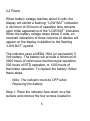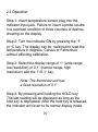
1
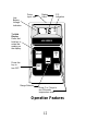
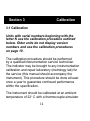
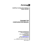
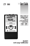
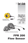
User’s Guide
MADE IN
305.4 °F
®
450 AET
THERMOCOUPLE THERMOMETER
TYPE E
Shop online at
ON
°F
HOLD
www.omega.com
e-mail: [email protected]
1°
0.1°
ON
OFF
°C
TEMPERATURE INDICATOR
450 SERIES
Digital Thermometers
OMEGAnet ® On-Line Service
www.omega.com
Internet e-mail
[email protected]
Servicing North America:
USA:
ISO 9001
Certified
Canada:
One Omega Drive, Box 4047
Stamford CT 06907-0047
Tel: (203) 359-1660
e-mail: [email protected]
976 Bergar
Laval (Quebec) H7L 5A1, Canada
Tel: (514) 856-6928
e-mail: [email protected]
FAX: (203) 359-7700
FAX: (514) 856-6886
For immediate technical or application assistance:
USA and
Canada:
Mexico:
Sales Service: 1-800-826-6342 / 1-800-TC-OMEGA®
Customer Service: 1-800-622-2378 / 1-800-622-BEST®
Engineering Service: 1-800-872-9436 / 1-800-USA-WHEN®
TELEX: 996404 EASYLINK: 62968934 CABLE: OMEGA
En Espan˜ol: (001) 203-359-7803
FAX: (001) 203-359-780
e-mail: [email protected]
[email protected]
Servicing Europe:
Benelux:
Postbus 8034, 1180 LA Amstelveen
The Netherlands
Tel: +31 (0)20 3472121 FAX: +31 (0)20 6434643
Toll Free in Benelux: 0800 0993344
e-mail: [email protected]
Czech Republic:
Frystatska 184, 733 01 Karvina´, Czech Republic
Tel: +420 (0)59 6311899 FAX: +420 (0)59 6311114
Toll Free: 0800-1-66342
e-mail: [email protected]
France:
11, rue Jacques Cartier
78280 Guyancourt, France
Tel: +33 (0)1 61 37 2900 FAX: +33 (0)1 30 57 5427
Toll Free in France: 0800 466 342
e-mail: [email protected]
Germany/Austria:
Daimlerstrasse 26, D-75392
Deckenpfronn, Germany
Tel: +49 (0)7056 9398-0
FAX: +49 (0)7056 9398-29
Toll Free in Germany: 0800 639 7678
e-mail: [email protected]
United Kingdom: ISO 9002 Certified
One Omega Drive
River Bend Technology Centre
Northbank, Irlam, Manchester
M44 5BD United Kingdom
Tel: +44 (0)161 777 6611
FAX: +44 (0)161 777 6622
Toll Free in United Kingdom:0800-488-488
e-mail: [email protected]
It is the policy of OMEGA to comply with all worldwide safety and EMC/EMI regulations that apply.
OMEGA is constantly pursuing certification of its products to the European New Approach
Directives. OMEGA will add the CE mark to every appropriate device upon certification.
The information contained in this document is believed to be correct, but OMEGA Engineering,
Inc. accepts no liability for any errors it contains, and reserves the right to alter specifications
without notice. WARNING: These products are not designed for use in, and should not be used
for, human applications.
RETURN REQUESTS/INQUIRIES
Direct all warranty and repair requests/inquiries to the OMEGA Customer Service
Department. BEFORE RETURNING ANY PRODUCT(S) TO OMEGA, PURCHASER
MUST OBTAIN AN AUTHORIZED RETURN (AR) NUMBER FROM OMEGA’S
CUSTOMER SERVICE DEPARTMENT (IN ORDER TO AVOID PROCESSING DELAYS).
The assigned AR number should then be marked on the outside of the return
package and on any correspondence.
The purchaser is responsible for shipping charges, freight, insurance and proper
packaging to prevent breakage in transit.
FOR WARRANTY RETURNS, please
have the following information
available BEFORE contacting OMEGA:
1. Purchase Order number under which
the product was PURCHASED,
2. Model and serial number of the
product under warranty, and
3. Repair instructions and/or specific
problems relative to the product.
FOR NON-WARRANTY REPAIRS, consult
OMEGA for current repair charges. Have the
following information available BEFORE contacting OMEGA:
1. Purchase Order number to cover the COST
of the repair,
2. Model and serial number of the product, and
3. Repair instructions and/or specific problems
relative to the product.
OMEGA’s policy is to make running changes, not model changes, whenever an improvement is possible. This affords our customers the latest in technology and engineering.
OMEGA is a registered trademark of OMEGA ENGINEERING, INC.
© Copyright 2003 OMEGA ENGINEERING, INC. All rights reserved. This document may not
be copied, photocopied, reproduced, translated, or reduced to any electronic medium or
machine-readable form, in whole or in part, without the prior written consent of OMEGA
ENGINEERING, INC.
Table of Contents
Section 1: Description
1.1 General Description……………2
1.2 Physical Description…………...3
1.3 Unpacking……………………… 3
1.4 Specification…………………… 4
Section 2: Operation
2.1 Principles of Operation………...7
2.2 Power…………………………… 8
2.3 Operation……………………….10
2.4 Maintenance……………………13
Section 3: Calibration
3.1 Calibration………………………14
Section 1
Description
1.1 General Description
Your hand-held, battery operated digital
temperature indicator is configured for compatibility
with one of five temperature transducers, J,K,E,T
RTD and Thermister.
Each of the configurations linearizes the analog
output from the transducer to produce a stable and
accurate digital temperature display. Plug-in type
input connectors are used for the transducer input
to provide quick connect and disconnect capability.
The indicator functions are controlled by the keyboard. The liquid crystal display exhibits the value
of the measurement, degrees Fahrenheit or Celsius,
and the low battery voltage indication.
The use of advanced digital design techniques
give the indicator extremely accurate readings and
exceptionally long battery life.
2
1.2 Physical Description
The indicator measures 45 mm (1.8 inches) in
Height, 85 mm (3.3 inches) in width, and 145 mm
(5.7 inches) in length. Weight is 230 grams (8.0
ounces). The case is constructed of high impact
plastic.
1.3 Unpacking
The indicator is supplied with the battery installed.
A quick electrical test should be performed to verify
that the indicator is operative. See 2.3 in Section 2
for operating instructions.
Contact our Instrument Repair Department
immediately if any problems are observed after
checking out operation of the unit.
3
Specifications
Display:
Liquid crystal display, 7.6 mm (0.3 in.) digit
Height
Operating temperature:
0 to 50°C (32 to 122°F) 0 to 75% Relative
Humidity
Storage Temperature:
-20 to 70°C (-4 to 158°F)
Battery:
NEDA 1604, 9 Volt
Battery Life:
Thermocouple-2000 hours minimum
Platinum RTD-500 hours minimum
Thermistor- 1200 hours minimum
NMRR:
50 dB @ 50±1 Hz, 0.1° range
35 dB @ 50±1 Hz or 60±1Hz, 1° range
CMRR:
140 dB @ 50±1 Hz, 0.1° range
120 dB @ 50±1 Hz or 60±1Hz, 1° range
4
Maximum Common Mode Voltage:
1000VAC(RMS), ±2000V Peak
Accuracy at 22°C (72°F)
1° range:
±0.8°C±0.1% rdg
±1.5°F±0.1% rdg
±0.25°C±0.1% rdg
±.45°F±0.1% rdg
0.1° range:
Stability with time:
90 days:
1 year:
add ±0.05% rdg.
add ± 0.1% rdg.
Stability with temperature:
Thermocouple:
zero: ±0.03°C/°C
span: ±0.02% rdg/°C (max)
reference junction tracking ±1.0°C (±1.8°F)
from 5°C to 45°C (41°F to 113°F)
Platinum RTD: ±0.02°C, ±0.01% rdg/°C
Thermistor: positive- ±0.02°C/°C
negative-±0.04°C/°C
5
450 Range Table
Type
K
Type
J
Type
E
Type
T
-189 C to +1372 C
-308 F to +2501 F
-139.8 C to +203.7 C
-219.7 F to +398.7 F
-194 C to +1200 C
-318 F to +2192 F
-117.4 C to +203.5 C
-179.4 F to +398.7 F
-212 C to +1000 C
-351 F to +1832 F
-137.2 C to +203.5 C
-215.0 F to +398.4 F
-217 C to +400 C
-360 F to +752 F
-148.2 C to +203.9 C
-234.8 F to +399.0 F
-233 C to +904 C
-388 F to +1660 F
-102.9 C to +203.5 C
-153.2 F to +398.3 F
-25.7 C to +103.2 C
-14.4 F to +217.8 F
1
0.1
1
0.1
1
0.1
1
0.1
1
RTD
0.1
Thermister
0.1
6
Section 2
Operation
2.1 Principles of Operation
The temperature indicator uses two ICs to digitize
and display the analog input signal.
One IC performs the conversion of the analog
input to the digital equivalent via 24 bit deltasigma analog to digital converter. Battery voltage
is also monitored by this IC and a thermistor
supplies the reference junction correction signal.
The other IC receives input from the analog
to digital converter, linearizes and drives the
LCD display. Front panel buttons are also
monitored.
7
2.2 Power
When battery voltage reaches about 6 volts, the
display will exhibit a flashing: “LOW BAT” indication.
A minimum of 20 hours of operation time remains
upon initial appearance of the “LOW BAT” indication.
When the battery voltage drops below 5 volts, an
overload indications of three columns of dashes will
appear on the display in addition to the flashing
“LOW BAT” symbol.
The indicator uses a NEDA 1604 (or equivalent) 9
Volt battery. The battery will provide a minimum of
2000 hours of continuous thermocouple operation,
500 hours of RTD operation, or 1200 hours of
thermistor operation. To replace the battery, follow
these steps.
Note: The indicator must be OFF when
Replacing the battery.
Step 1: Place the indicator face down on a flat
surface and remove the four screws located in
8
the recesses or each corner of the case bottom.
Step 2: Carefully pull the case halves straight
apart so as not to damage the internal connectors.
Step 3. Install the new battery. Close the case and
reinstall the four screws.
9
2.3 Operation
Step 1: Insert temperature sensor plug into the
indicator input jack. Failure to insert a probe results
in a overload condition of three columns of dashes
showing on the display.
Step 2: Turn the indicator ON by pressing the °F
or °C key. The display can be switched to read the
temperature in degrees Celsius or Fahrenheit
without affecting calibration.
Step 3: Select the display range of 1° (wide range,
low resolution) or 0.1° (narrow range, high
resolution) with the 1°/0.1° key.
Note: The thermistor unit has
a fixed resolution of 0.1°.
Step 4: By pressing and holding the HOLD key,
The last reading will be displayed as long as the
hold key is depressed. After the hold key is released,
the indicator will revert to its normal display mode.
10
Step 5: Observe and or record the temperature
value.
Step 6: Turn instrument off by pressing the OFF
key.
11
Low
Battery
Voltage
Indication
Probe
Input Jack
Display
Value
F/C
Indication
F
C
To Hold
Display
Press and
hold key to
retain last
reading on
the display.
450 SERIES
ON
F
.
HOLD
1
0.1
Press this
key to
turn OFF
ON
C
.
OFF
Range Selector
Press C or F keys to
turn ON and/or
temperature scale
Operation Features
12
2.4 Maintenance
Normal maintenance of the indicator consists of
occasional cleaning with a soft, damp cloth,
replacement of the battery as required, and
calibration as outlined in Section 3.
13
Section 3
Calibration
3.1 Calibration
Units with serial numbers beginning with the
letter N use the calibration procedure outlined
below. Older units do not display version
numbers and use the calibration procedures
on page 19 .
The calibration procedure should be performed
by a qualified instrumentation service technician.
The indicator may be brought to any instrumentation
calibration and repair laboratory (metrology lab) for
the service (this manual should accompany the
instrument). This procedure should be done at least
once a year to guarantee continued performance
within the specification.
The instrument should be calibrated at an ambient
temperature of 22° C with a thermocouple simulator
14
with a minimum accuracy of ±0.1 degree
Fahrenheit or ±0.2 degree Centigrade.
Step 1. Ensure the unit is turned off. Connect the
output of the thermocouple simulator to the input
of
the
indicator
using
the
appropriate
thermocouple wire. Set the simulator output to 0°C
Step 2. Locate the calibration switch on the back
of the case labeled “Zero”. Remove the black
button. Using a small screw drive or flat end of the
trimmer pot, press the cal switch once. The display
should read version and then switch to ambient
temperature; press the switch one more time. The
display should indicate .0.0 °C
Step 3. Press the switch one more time, the
display should read max calibration temperature
(for K type: 13.2.0, for J type: 9.6.0, for T type:
3.5.0, and for E type: 9.5.0) Now, set the simulator
output to display temperature as show in table
below.
15
NOTE: If you want to cancel the calibration
mode press OFF button in front of the unit.
For T/C type
K set simulator @ 1320 °C
J set simulator @ 960 °C
T set simulator @ 350 °C
E set simulator @ 950 °C
Press the switch one more time and wait for a few
seconds until display switches to 0.0 set simulator
to 0°C. Press switch one more time. Unit should
shut-off.
Step 4. Now, turn the unit on from front panel.
Make sure the unit in degree C mode. Verify that
the unit is within specification throughout its range.
Step 5. If unit does not meet specification as 0°C
then repeat calibration procedure,
Instead of setting simulator as 0°C, set it at the
temperature indicated by the unit in measurement
mode as 0°C. For example in measure mode, unit
may display .2°C with simulator as 0°C. During
16
calibration procedure, set simulator at .2°C instead
of 0 °C. Repeat the calibration procedure again.
Step 6. Verify calibration once finished.
17
Ra
Rb
Rc
GND
Ref J
+IN
-1.23V
+3.7V
10
2
5
1
6
3
8
9
4
7
Ra - Full Scale Adj.
Rb Zero Adj.
Rc +Full Scale Adj.
18
Calibration- Thermocouple Type K, J and
T
and E
Equipment List
•
•
•
•
4 ½ digit voltmeter
Voltage Calibrator:
Resolution, 1uV; accuracy ±0.01% (±2uV)
Ice Bath, 0.00 °C ± 0.05°C
Jumper lead terminated in mini-clips
For optimum results, the calibration should be
performed with an ambient temperature from 20°
24°C (68° to 75°F). Refer to the figure on the
previous page for the locations of all testpoints
and adjustments.
a.
Turn the indicator ON by pressing the °C key.
b.
For types K, J, E and T units only, switch
the indicator to the 0.1° range.
19
c.
d.
Remove the bottom case of the indicator.
Adjust the voltage calibrator for an output of
0.000mV and connect the minus lead from the
calibrator to “GND” and the positive lead
from the calibrator to “;+IN”, on the indicator
printed circuit board.
e.
Disable the reference junction by jumpering
together the “REF J” and “GND” testpoints,
using a jumper lead terminated in mini-clips.
f.
Adjust Rb for an indicator display of 0.0°C.
g.
Connect the DVM LO lead to “GND”, on the
indicator printed circuit board.
h.
Using HI lead of DVM, measure voltage
at the “-1.23V” testpoint: disregarding
polarity indication, record the voltage.
i.
Move the DVM HI lead to the “3.7V”
testpoint and record the voltage (disregard
20
polrity).
j.
The voltage measured at the “3.7V” testpoint should be 3.007 times larger than
the voltage measured at the “-1.23V” testpoint. Adjust Rc (which varies the +3.7V
line to attain the proper ratio.
k.
Switch the indicator to the 1° range.
l.
Adjust the voltage calibrator for an output of
+53.782mV for type K; +57.942mV for type J;
+75.983mV for type E; +18.824mV for type T;
m. Adjust Ra for an indicator display of +995°C
for type E, or 1000°C for type J, or +1340°C
for type K, or +367°C for type T.
n.
Reassemble the indicator.
o.
Perform the zero calibration.
21
Calibration- Thermistor Type
Equipment List
•
•
•
•
4 ½ digit voltmeter
Precision decade box:
Resolution, 0.01 ohm ; accuracy ±0.02%
Ice Bath, 0.00 °C ± 0.05°C
Electro Scientific Industries DB-62 or
equivalent
a.
Turn the indicator ON by pressing the °C key.
b.
Remove the bottom case of the indicator.
c.
Connect a precision resistance box to the
terminals on the phone input jack; set the
resistance box to 7,280 ohms.
d.
Connect the DVM LO lead to “GND”, on the
indicator printed circuit board.
e.
Using HI lead of DVM, measure voltage
22
at the “-1.23V” testpoint: disregarding
polarity indication, record the voltage.
f.
Move the DVM HI lead to the “3.7V”
testpoint and record the voltage (disregard
polarity).
g.
The voltage measured at the “3.7V” testpoint should be 3.007 times larger than
the voltage measured at the “-1.23V” testpoint. Adjust Rc (which varies the +3.7V
line to attain the proper ratio.
h.
Adjust Rb for an indicator display of 0.2°C.
i.
Set the resistance box to 148.4 ohms.
j.
Adjust Ra for an indicator display of +101.0°C.
k.
Reassemble the indicator.
l.
Perform the zero calibration
23
Calibration- Platinum RTD
Equipment List
•
•
•
•
•
4 ½ digit voltmeter
Precision decade box:
Resolution, 0.01 ohm ; accuracy ±0.02%
Ice Bath, 0.00 °C ± 0.05°C
Electro Scientific Industries DB-62 or
equivalent
a.
Turn the indicator ON by pressing the °C key.
b.
Remove the bottom case of the indicator.
c.
Connect a precision resistance box to the
terminals on the RTD input jack and set the
resistance box to 100.04 ohms.
d.
Using HI lead of DVM, measure voltage
at the “-1.23V” testpoint: disregarding
polarity indication, record the voltage.
24
e.
Move the DVM HI lead to the “3.7V”
testpoint and record the voltage (disregard
polrity).
f.
The voltage measured at the “3.7V” testpoint should be 3.007 times larger than
the voltage measured at the “-1.23V” testpoint. Adjust Rc (which varies the +3.7V
line to attain the proper ratio.
g.
Adjust Rb for an indicator display of 32.2°F.
h.
Adjust Ra for an indicator display of +196.0°C.
i.
Reassemble the indicator.
Perform the zero calibration
25
Zero Calibration
a.
Turn the indicator on by pressing the °C
key.
b.
Set the indicator to the 0.1° range.
c.
Connect the ice bath probe to the indicator
Input jack.
d.
Place the probe in a stable ice bath (0.00C
±0.05°C and adjust the ZERO pot (Rb)
located beneath the plug on the rear case
for an indicator display of 0.0°C.
e.
Replace the rubber plug.
Calibration is complete.
26
WARRANTY/DISCLAIMER
OMEGA ENGINEERING, INC. warrants this unit to be free of defects in materials and
workmanship for a period of 13 months from date of purchase. OMEGA’s Warranty
adds an additional one (1) month grace period to the normal one (1) year product
warranty to cover handling and shipping time. This ensures that OMEGA’s customers
receive maximum coverage on each product.
If the unit malfunctions, it must be returned to the factory for evaluation. OMEGA’s
Customer Service Department will issue an Authorized Return (AR) number immediately upon phone or written request. Upon examination by OMEGA, if the unit is found to
be defective, it will be repaired or replaced at no charge. OMEGA’s WARRANTY does not
apply to defects resulting from any action of the purchaser, including but not limited to
mishandling, improper interfacing, operation outside of design limits, improper repair, or
unauthorized modification. This WARRANTY is VOID if the unit shows evidence of having
been tampered with or shows evidence of having been damaged as a result of excessive
corrosion; or current, heat, moisture or vibration; improper specification; misapplication;
misuse or other operating conditions outside of OMEGA’s control. Components which
wear are not warranted, including but not limited to contact points, fuses, and triacs.
OMEGA is pleased to offer suggestions on the use of its various products.
However, OMEGA neither assumes responsibility for any omissions or errors
nor assumes liability for any damages that result from the use of its products
in accordance with information provided by OMEGA, either verbal or written.
OMEGA warrants only that the parts manufactured by it will be as specified
and free of defects. OMEGA MAKES NO OTHER WARRANTIES OR
REPRESENTATIONS OF ANY KIND WHATSOEVER, EXPRESS OR IMPLIED,
EXCEPT THAT OF TITLE, AND ALL IMPLIED WARRANTIES INCLUDING ANY
WARRANTY OF MERCHANTABILITY AND FITNESS FOR A PARTICULAR
PURPOSE ARE HEREBY DISCLAIMED. LIMITATION OF LIABILITY: The
remedies of purchaser set forth herein are exclusive, and the total liability of
OMEGA with respect to this order, whether based on contract, warranty,
negligence, indemnification, strict liability or otherwise, shall not exceed the
purchase price of the component upon which liability is based. In no event
shall OMEGA be liable for consequential, incidental or special damages.
CONDITIONS: Equipment sold by OMEGA is not intended to be used, nor shall it be
used: (1) as a “Basic Component” under 10 CFR 21 (NRC), used in or with any nuclear
installation or activity; or (2) in medical applications or used on humans. Should any
Product(s) be used in or with any nuclear installation or activity, medical application,
used on humans, or misused in any way, OMEGA assumes no responsibility as set
forth in our basic WARRANTY/ DISCLAIMER language, and, additionally, purchaser will
indemnify OMEGA and hold OMEGA harmless from any liability or damage
whatsoever arising out of the use of the Product(s) in such a manner.
Where Do I Find Everything I Need for
Process Measurement and Control?
OMEGA…Of Course!
Shop online at www.omega.com
TEMPERATURE
Thermocouple, RTD & Thermistor
Probes, Connectors, Panels &
Assemblies
Wire: Thermocouple, RTD &
Thermistor
Calibrators & Ice Point References
Recorders, Controllers & Process Monitors
Infrared Pyrometers
PRESSURE, STRAIN
AND FORCE
Transducers & Strain Gages
Load Cells & Pressure Gages
Displacement Transducers
Instrumentation & Accessories
FLOW/LEVEL
Rotameters, Gas Mass Flowmeters
& Flow Computers
Air Velocity Indicators
Turbine/Paddlewheel Systems
Totalizers & Batch Controllers
pH/CONDUCTIVITY
pH Electrodes, Testers & Accessories
Benchtop/Laboratory Meters
Controllers, Calibrators, Simulators
& Pumps
Industrial pH & Conductivity
Equipment
DATA ACQUISITION
Data Acquisition &
Engineering Software
Communications-Based
Acquisition Systems
Plug-in Cards for Apple, IBM
& Compatibles
Datalogging Systems
Recorders, Printers & Plotters
HEATERS
Heating Cable
Cartridge & Strip Heaters
Immersion & Band Heaters
Flexible Heaters
Laboratory Heaters
ENVIRONMENTAL
MONITORING AND CONTROL
Metering & Control Instrumentation
Refractometers
Pumps & Tubing
Air, Soil & Water Monitors
Industrial Water & Wastewater
Treatment
pH, Conductivity & Dissolved
Oxygen Instruments
M0099/0603