1
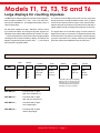
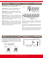
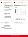
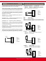
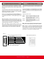
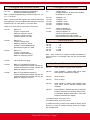
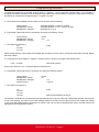
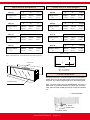
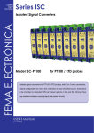
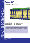
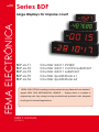
Series BDF
Large
Displays
FEMA ELECTRÓNICA
Large Displays for impulse count
BDF-xx-T1
BDF-xx-T2
BDF-xx-T3
BDF-xx-T5
BDF-xx-T6
Counter add + inhibit
Counter add + control substract
Counter add + substract
Counter quadrature x1
Counter quadrature x4
IDEAL SOLUTION for reading counting values at long distances from standard
signals NPN, PNP, MECHANICAL, NAMUR, ... Display direct or scalable to
engineering units Very strong housing and electrically protected units, designed
for all type of industrial applications.
USER’S Manual
(1275r01)
User’s Manual BDF-xx-T1, T2, T3, T5 and T6
Models T1, T2, T3, T5 and T6
Large displays for counting impulses
The BDF series of large displays for impulse counting applications is made of models «T1», «T2» , «T3», «T5» and «T6».
All units are available in 4 and 6 digits format with 57mm or
100mm digit height.
All units have negative led sign, «RESET» function active
by mechanical contact, and recognize impulse signals from
standard sensors NPN, PNP, Mechanical Contact, Encoder,
... Counted impulses are scaled with internal programmable
«Scaling Factors» before loaded on display. This allows the
display of engineering units (meters, liters, ... ). The decimal
point position is programmable.
The mechanical of the BDF instruments is a very strong and
sturdy aluminium housing anodized in black color, for panel
mount, and for wall mount as an option. The front lens is antirreflexive and is firmly inserted on the aluminium profile with a
rubber gasket around, providing IP65 protection on the front.
The signal wires are connected to plug-in screw clamps for
higher security of the connections, accessible at the rear side
of the instrument. The power is connected to a 3 terminal plug
(2 power connections and 1 earth) containing an integrated
protection fuse and an additional fuse as spare part.
Order reference
Model
Size
BDF
-
24
-24
-44
-26
-46
-
T3
-T1
-T2
-T3
-T5
-T6
Power
-
0
-0 (230 Vac)
-1 (115 Vac)
-6 (24 Vdc
isolated)
Color
-
R
-Red
-Green
-
Others
Adjust
Sensor
---
1imp=+1
NPN
1imp=+1
1imp=3
1imp=1.5
...
NPN
PNP
Namur
Contact
...
-65 (IP65)*
-(empty)
(check for
availability)
* the IP65 option uses a completely
different type of housing from the
indicated in this documentation.
Check the BDF IP65 housing documentation for more information.
Sizes
SIZE BDF-24 - Instrument with 4 digits
digit 57mm height (2,3’’)
SIZE BDF-44 - Instrument with 4 digits
digit 100 mm height (4,0’’)
SIZE BDF-26 .- Instrument with 6 digits
57mm digit height
SIZE BDF-46 .- Instrument with 6 digits
100mm digit height
FEMA ELECTRÓNICA - Page 2
User’s Manual BDF-xx-T1, T2, T3, T5 and T6
Models
Front view
MODEL BDF-xx-T1 .- Counter ADD with INHIBIT function
when connecting «Input2» to a logical «0» signal.
A
B
Negative sign
MODEL BDF-xx-T2 .- Counter ADD with SUBSTRACT function when connecting «Input2» to a logical «0» signal.
MODEL BDF-xx-T3 .- Counter ADD and SUBSTRACT with
independent inputs. ADD impulses on «Input1» and SUBSTRACT impulses on «Input2»
MODEL BDF-xx-T5 .- Counter for quadrature signals
(typical from bidirectional encoder) with automatic ADD/
SUBSTRACT depending on phase differences between
signals «A» and «B» (encoder turning clockwise or counterclockwise). 1 full cyle is 1 impulse.
MODEL BDF-xx-T6 .- Counter for quadrature signals
(typical from bidirectional encoder) with automatic ADD/
SUBSTRACT depending on phase differences between
signals «A» and «B» (encoder turning clockwise or counterclockwise). 1 full cyle is 4 impulses.
D
Negative sign
Decimal point selectable
Decimal point selectable
The BDF Counter units are available in 4 and 6 digits format.
All digits are 7 segment LED type with decimal point, negative
sign and red color
Leds «B» and «D» are lighted when the unit is being reprogrammed through the «Programming Terminal» on the rear
cover
Digits «A» are only available in units with 4 digits. These small
digits will light only when the unit is being reprogrammed
through the «Programming Terminal» on the rear cover.
Power supply connections
The power connector allows one terminal for earth and two
power terminals. Internal fuse is integrated on the connector
and an additional fuse is available as a spare part. The value
of the fuses depends on the power supply, and is according
to rule IEC127/2
230 Vac - 200 mA fuse time-lag
115 Vac - 400 mA fuse time-lag
24 Vdc - 350 mA fuse fast
Powered
230 Vac (115 Vac optional)
Powered
24 Vdc Isolated
+
Rear view
Programming Terminal
Terminal for input
impulses and control
-
Fuse
FEMA ELECTRÓNICA - Page 3
Power
(includes fuse)
User’s Manual BDF-xx-T1, T2, T3, T5 and T6
General specifications
DISPLAY
4 or 6 digits in red color
7 segment Led
reading from -9999 to 9999 in 4 digits
reading from -999999 to 999999 in 6 digits
decimal point selectable
digit 57 mm (2,3”) in BDF-24 and BDF-26
digit 100 mm (4,0”) in BDF-44 and BDF-46
antirreflexive front filter
IP65 front protection
SENSORS
NPN Vmax on terminals +28Vdc
PNP Vmax on terminals +28Vdc
NamurVmax on terminals +28Vdc
mechanical contact
Pick-up
Internal jumpers
The instrument can select two levels of trigger for different
NPN, PNP and NAMUR sensors, different types of input signals and two levels of filters. To access the selection jumpers,
unscrew the rear side cover and locate the «Control Board»
with the selection jumpers.
«Control board»
PICK-UP
150 mVpp sensibility
100 mV hysteresis
26,5 KOhms Impedance
60Hz
Vmax ±50Vdc
Note - Sensor type is jumper selectable
FREQUENCY model «T1» maximum 10 KHz
model «T2» maximum 10 KHz
model «T3» maximum 4 KHz
model «T5» maximum 5 KHz
model «T6» maximum 2,5 KHz
Vexc
+15 Vdc (±20%, 100mA)
ENVIRONMENTAL DATA
Working Temp. 0/+50ºC (32/122 ºF)
Storage Temp. -20/+85°C (-4/185ºF)
Rel. Humidity 0 to 85% non condensated
HOUSING
extruded aluminium
anodized in black color
for panel mount (optional wall mount)
POWER SUPPLY
standard 230 Vac 50/60 Hz
(optional 115 Vac 50/60 Hz)
(optional 24 Vdc isolated)
* Trigger levels for NPN, PNP, NAMUR
Trigger Level «LOW» .- Jumper H,G Closed
Logical Level «1»>3.75 Vdc
Logical Level «0»<1.50 Vdc
Trigger Level «HIGH» .- Jumpers H,G Open
Logical Level «1»>7.50 Vdc
Logical Level «0»<5.50 Vdc
* Antirrebound filter .- Jumpers J,K
Closed - Open-
Antirrebound filters at < 100 Hz
Antirrebound filters at < 10 KHz
Note .- Use filters at <100Hz for inputs type mechanical contact, in order to
filter rebounds on the contact.
CONSUMPTION
6 VA in series BDF-24 and BDF-26
12 VA in series BDF-44 and BDF-46
FEMA ELECTRÓNICA - Page 4
User’s Manual BDF-xx-T1, T2, T3, T5 and T6
Connections terminal
The input signal is connected to the 5 pole plug-in screw
terminal at the rear side cover of the instrument.
Terminal «B» provides a +15 Vdc (maximum 100 mA) signal
to power-up sensors and transducers. Do not use this terminal
to power sensors and transducers that need higher current.
Sensor type selection and connection
MECHANICAL CONTACT
Jumpers ADF
«INPUT1» terminal «C» (Signal) and «A» (Common)
«INPUT2» terminal «D» (Signal) and «A» (Common)
Note - close internal jumpers J,K. See section 6
The 2 inputs of the instrument are connected to terminals
«C» (Input1) and «D» (Input2). The function for «Input2» is
dependent on the model.
Model BDF-xx-T1 .- «Input2» is INHIBIT function, when connected to a logical «0» state
Model BDF-xx-T2 .- «Input2» activates SUBSTRACT function when connected to a logical «0» state
Model BDF-xx-T3 .- Impulses at «Input2» SUBSTRACT
E
RESET
D
«INPUT2»
C
«INPUT1»
B
Vexc
A
COMMON
NPN Jumpers ADF
PNP Jumpers ABCDF
«INPUT1» terminal «C» (Signal), «A» (Com) and «B» (Vexc)
«INPUT2» terminal «D» (Signal), «A» (Com) and «B» (Vexc)
Model BDF-xx-T5 .- «Input1» and «Input2» are associated
to signals «A» and «B» of quadrature signals (typical signal
from bidirectional encoder)
Model BDF-xx-T6 .- «Input1» and «Input2» are associated
to signals «A» and «B» of quadrature signals (typical signal
from bidirectional encoder)
Signal 2
Signal 1
+15 Vdc
0 Vdc
All BDF Counter units have «RESET» function by mechanical contact on the rear side of the instrument. Connection
is done betwen terminals «E» (Reset) and «A» (Common).
+15 Vdc
0 Vdc
E
RESET
D
«INPUT2»
C
«INPUT1»
B
Vexc
A
COMMON
PICKUP Jumpers AE
«INPUT1» terminal C (Signal) and A (Common)
«INPUT2» not connected
RESET
E
RESET
D
«INPUT2»
C
«INPUT1»
B
Vexc
A
COMMON
Señal1
0 Vdc
E
RESET
D
«INPUT2»
C
«INPUT1»
B
Vexc
A
COMMON
NAMUR Jumpers BCDF
«INPUT1» terminal B (Vexc) and C (Signal)
«INPUT2» terminal B (Vexc) and D (Signal)
Signal 2
Signal 1
+8V2
FEMA ELECTRÓNICA - Page 5
+8V2
E
RESET
D
«INPUT2»
C
«INPUT1»
B
Vexc
A
COMMON
User’s Manual BDF-xx-T1, T2, T3, T5 and T6
Programming the instrument
Programming codes
The BDF Counter instruments are configured by programming codes that activate internal «scale factors», decimal
points, and other elements which scale the signal counted
on display.
The programming codes are made of 2 digits identifying the
code, and a third digit identifying the value assigned to the
code.
The programming of these codes is done through the 15 pin
SUB-D connector at the rear side of the instrument. A «KBD
Programming Keyboard» is needed, or the connections
shown in Figure 1 need to be set-up.
Buttons «1» to «6» introduce the numerical characters 1, 2,
3, 4, 5 and 6 on display, button «#» executes «ENTER» on
the displayed code. Button «*» adds negative sign in some
codes.
Note - When KBD (or contacts indicated in Figure 1) are connected to the BDF, the point placed under the negative sign
will light. This led must be «on» during the reprogramming
of the unit (if the led is not lightning, but the led on top of the
negative sign lights, then press «*» to switch leds).
Note - When KBD (or contacts indicated in Figure 1) are
connected to the BDF Ratemeter with 4 digits, the 2 small 7
segment displays on top left part will light. These digits are
needed to program some codes which are 6 digit codes.
Code «41» with value «1» is represented as «41 1#». Button
«#» acts as a validation of the code and value entered. If this
button is not pressed, the unit will not validate the new value.
EXAMPLE
Introducing code «41 1#»
Press 4 Press 1 Press 2 Press # Number 4 appears on display, to the left
Number 1 appears on display, to the left
The current value for code 41 appears to
the right (it can be 1 or 2)
Number 2 appears on display, to the right
replacing the previous value
Validates the code and the value entered
(in this case 41 1)
Note .- After 6 seconds without introducing data, the instrument will cancel the programming code without validation.
Note .- Codes «1», «2» and «3» are special codes composed
by only 1 digit. The value is a 6 digit numerical value and will
load on display as soon as the code is pressed. The way to
modify this value is to modify each digit value independently
by pressing 1 to 6 and then # to validate the whole.
Figure 1
Function of the programming terminal pins
9
10
11
12
13
14
15
1
2
3
4
5
6
7
8
Pin 1 common
Pin 9
Pin 2
Pin 10
Pin 3
Pin 11
Pin 4
Pin 12
Pin 5
KBD programming keyboard
button «*»
button «6»
button «5»
button «4»
button «3»
button «2»
button «1»
button «# (ENTER)»
Pins 6, 13 and 14 shortcircuited
Pin 7, 8 and 15 leave open
FEMA ELECTRÓNICA - Page 6
User’s Manual BDF-xx-T1, T2, T3, T5 and T6
Configure the counter model
«41 -1#»
Resets the instrument configuration.
Activates the default parameters
Note - To place the negative sign, introduce codes «4», «1»,
«1», «*» and «#»
Note .- The led under the negative sign must be ON during
the programming. If it is not lightning and the led on top of the
negative sign is on, then press «*» to swtich leds.
Codes «43» select the type of counter to be active
«43 1#»
BDF-xx-T1
«Input1» impulse input
Maximum frequency 9 KHz
«Input2» control for inhibit
Inhibits at logical «0» state
«43 2#»
BDF-xx-T2
«Input1» impulse input
Maximum frequency 9 KHz
«Input2» control Add/Substract
Substracts at logical «0» state
«43 3#»
BDF-xx-T3
«Input1» impulse Add
«Input2» impulse Substract
Maximum frequency 5 KHz
«43 4#»
this code does not apply
«43 5#»
BDF-xx-T5 (quadrature signal x1)
«Input1» bidirectional encoder channel «A»
«Input2» bidirectional encoder channel «B»
Maximum frequency 4,5 KHz
«43 6#»
BDF-xx-T6 (quadrature signal x4)
«Input1» bidirectional encoder channel «A»
«Input2» bidirectional encoder channel «B»
Maximum frequency 4,5 KHz
Configure the multipliers
«3»
«45
«45
«45
«45
«45
«Scale Factor»
multiplier between «0.0000» and «5.9999»
By default it is «1.0000»
1#»
2#»
3#»
4#»
5#»
«44 1#»
«44 2#»
«Multiplier» x1
«multiplier» x0.1
«multiplier» x0.01
«multiplier» x0.001
«multiplier» x0.0001
«flange multiplier» x1
Counts on down flange
«flange multiplier» x2
Counts on down and up flanges
Not compatible with code «43 6E»
Reduces maximum frequencies to half
Decimal point
«46
«46
«46
«46
«46
1#
2#
3#
4#
5#
0
»
0.0
» 0.00
» 0.000
»0.0000
Note - same codes but in negative, enable visualization of
zeros to the left.. For example code «46 -2E» will visualize
00000.0
Functions with reset and alarms
«56 1E»
Press «RESET», display loads «000000»
«56 2E»
Press «RESET» , display loads «AL2» value
and impulses substract from display
«56 3E»
Does not apply
«56 4E»
Does not apply
«56 5E»
Press «RESET», display loads «000000» and
when «AL2» value is reached, display loads
«000000»
«56 6E»
Press «RESET», display loads «AL2» value and
impulses substract from display. When reaching «000000» displays loads «AL2» value, and
impulses substract from display
«1»Displays value of memory «AL1»
«2»Displays value of memory «AL2»
To modify the memory values once loaded on display, press
buttons 1,2,3,4,5,6 to modify each digit. Press «#» to apply
the modified value.
FEMA ELECTRÓNICA - Page 7
User’s Manual BDF-xx-T1, T2, T3, T5 and T6
Default parameters
«41 1#»
«42 3#»
«43 1#»
«44 1#»
«45 1#»
«46 1#»
«61 4#»
«62 1#»
«63 1#»
«64 4#»
«65 1#»
«51 2#»
«52 3#»
«53»
«54 3#»
«55»
«56 1#»
«66 1#»
«1»
«2»
«3»
Default
Default
«Input1» input, «Input2» inhibit
«Flanges multiplier» x1
«Multiplier» x1
No decimal point
Default
Default
Default
Default
Default
«AL1» and «AL2» assigned to counter
Default
Default
Default
Default
Normal reset
Default
500
value for memory «AL1»
1000
value for memory «AL2»
1.0000 «scale factor»
Limit on the internal counter
The BDF Counter instruments work with a 23 bit internal
counter, allowing a maximum of 8.388.608 impulses to be
counted (more than 8 million impulses). If this value is exceeded the sign led will activate and the counting will be substracting from the display. Do a «RESET» and the counter will
recover normal functionality. Also internal memory «AL2» can
be programmed to release a «RESET» automatically when
a predefined value on display is reached (code «56 5E»).
FEMA ELECTRÓNICA - Page 8
User’s Manual BDF-xx-T1, T2, T3, T5 and T6
Programming example
The default programming for the BDF Counter units is 1 impulse = 1, this means each impulse adds +1 to the display. If
changing this relation is needed, then the programming codes need to be accessed to change the scale factors of the unit.
We take as an example the reprogramming to 1 impulse = 0,2785.
a.- The scale factors available and the values we can activate are the following :
«Scale Factor»
«Multiplication Factor»
«Multiplication Flanges»
selectable between -5.9999 to +5.9999
selectable between x1, x0.1, x0.001, x0.0001
selectable at x1 or x2
b.- To generate a total scale factor of 0,2785 we can assign the following values :
«Scale Factor» = 2,785
«Multiplication Factor»
= x0.1
«Multiplication Flanges» = x1
c.- The codes to program are :
«3»
«45 2#»
«44 1#»
2,785
With this programming, each impulse received will add +0,2785 on memory. When 10 impulses have been received, display
will show «0002».
d.- To program the same relation 1 impulse = 0,2785 but with 1 decimal, we program the following way :
1 imp = +0,2785 with reading XXX.X
which is the same as 1 imp = 2,785 and light the decimal point :
e.- To generate a total scale factor of 2,785 we can assign the following values :
«Scale Factor» = 2,785
«Multiplication Factor»
= x1
«Multiplication Flanges» = x1
«Decimal Point»
= XXX.X
c.- The codes to program are :
«3»
«45 2#»
«44 1#»
«46 2#»
2,785
Decimal point lightning at XXX.X
The possible combinations of scale factors and decimal points are very big. Take into consideration that the decimal point
is only a led lightning, but it will not move the readings neither to the left nor to the right, and it will not multiply the reading
in any case. Start always defining parameter «3» which is the only one able to define precise values, and then look for the
appropriate fixed multiplication factors.
FEMA ELECTRÓNICA - Page 9
User’s Manual BDF-xx-T1, T2, T3, T5 and T6
Mechanical dimensions
Size 24
4 digits 57mm (2’’)
Size 44
4 digits 100mm
(4’’)
Size 26
6 digits 57mm (2’’)
Size 46
6 digits 100mm
(4’’)
A
B
C
264mm 120mm (10,40’’)
(4,75’’)
A
B
B
384mm 120mm (15,12’’)
(4,75’’)
A
B
668mm 180mm (27,10’’)
(7,09’’)
4 digits 57mm (2’’)
4 digits 100mm (4’’)
(4,41’’)
D
6 digits 57mm (2’’)
Size 46
E
376mm 112mm (14,80’’)
(4,40’’)
(4,41’’)
E
472mm 172mm (18,58’’)
(6,77’’)
Size 26
112mm
112mm
D
(4,41’’)
E
256mm 112mm (10,07’’)
(4,40’’)
Size 44
112mm
C
D
(4,41’’)
C
Size 24
112mm
C
480mm 180mm (18,90’’)
(7,09’’)
A
Panel cut-out and weights
D
6 digits 100mm (4’’)
E
680mm 172mm (36,77’’)
(6,77’’)
weight
2.3 Kg
(5 lbs)
weight
5.0 Kg
(11 lbs)
weight
2.7 Kg
(6 lbs)
weight
5.7 Kg
(12,5 lbs)
PANEL CUT-OUT
Note .- add 27mm to the «C» dimension for the power supply plug
E
Rear cover
D
C
B
Panel width
Max. 14 mm (0,55’’)
Min. 2,5 mm (0,10’’)
Panel installation
A
Antirreflexive filter
Introduce instrument «1» into the panel cut-out and place the
fixation piece «3» on each side. Place screw «2» through fixation piece «3» until it presses the panel «4» and is firmly fixed.
Note - The front of the instrument is sealed IP65. To have the
same level of protection between the panel and the instrument, place a rubber profile (squared or round) as indicated
«5».
1- Instrument BDF
2- Screw
3- Fixation tool
4- Panel
5- Rubber profile
FEMA ELECTRÓNICA - Page 10
User’s Manual BDF-xx-T1, T2, T3, T5 and T6
Warranty
CE Declaration of conformity
All instruments are warranted against all manufacturing
defects for a period of 24 MONTHS from the shipment date.
This warranty does not apply in case of misuse, accident or
manipulation by non-authorized personnel. In case of malfunction get in contact with your local provider to arrange for
repair. Within the warranty period and after examination by
the manufacturer, the unit will be repaired or substituted when
found to be defective. The scope of this warranty is limited to
the repair cost of the instrument, not being the manufacturer
eligible for responsibility on additional damages or costs.
Manufacturer FEMA ELECTRÓNICA, S.A.
Altimira 14 - Pol. Ind. Santiga
E08210 - Barberà del Vallès
BARCELONA - SPAIN
www.fema.es - [email protected]
Series- Models
BDF-24 y BDF-44
T1, T2, T3, T5 and T6
The manufacturer declares that the instruments indicated
comply with the directives and rules indicated below.
Directive of electromagnetic compatibility 2004/108/CEE
Directive of low voltage 73/23/CEE
Security rules
Emission rules
Immunity rules
61010-1
50081-2
50082-1
NOTE .- During an electromagnetic disturbance (10V/m) it is permitted a worst case error of 1% of
the A/D range. The instrument will recover automatically its functionality when the disturbance stops,
without need of the operator to reset or restart.
Barberà del Vallès October 2009
Daniel Juncà - Quality Manager
Precautions on installation
INSTALLATION PRECAUTIONS.- The installation and
operation of this instrument must be done by qualified
operators. This instrument DOES NOT have power switch
and will start to operate as soon as the power supply is
connected. The instrument has an internal protection fuse, according to
IEC-127/2, and is located inside the power-supply connector. The values are
Fuse 200 mA Time Lag (for 230 Vac power)
Fuse 400 mA Time Lag (for 115 Vac power)
Fuse 350 mA Fast (for 24 Vdc power)
When the instrument is used to control machines or processes where the
personnel or the process can be damaged, the appropriate security elements must be added to the system in order to protect the operator and /
or the system.
SAFETY PRESCRIPTIONS.- This instrument has been designed and verified according to the UNE-20553 rules and is delivered in perfect
conditions of operation. This manual contains the adequate information for the electrical installation. Before starting operations for
connections, readjustment, substitution, maintenance, repair, etc,
the instrument must be unplugged from the power supply. The instrument
must be installed in places with good ventilation to avoid excessive heating,
and far from sources of electrical noise or magnetic field generators, such as
power relays, electrical motors, speed controls, etc... The instrument can not
be installed in open places. Do not use until the installation is finished. The
instrument is designed to be mounted on a metallic panel with the adequate
protections. DO NOT clean the front lens with abrasive products (such as
solvents, alcohol, etc) use a clean and water humid rag. Do not expose the
instrument to excessive moisture. DO NOT operate the unit in the presence
of flammable gases or fumes.
EXCITATION VOLTAGE Vexc.Instruments BDF-xx-32 and BDF-xx-36 supply an excitation voltage of 10 to
24 Vdc (50mA) to power transducers, available between terminals A and C.
Do NOT connect these terminals to an external power supply, permanent
damages may result on both instruments.
POWER SUPPLY .- Connect the Power Supply to the terminals indicated in
this manual. Verify that the voltage and frequency of the
power supply is according to the voltage and frequency
values indicated in the label attached to the unit. DO
NOT connect the instrument to power lines which are
overloaded, or power lines with loads working in ON/OFF cycles, or with
inductive loads.
SIGNAL WIRING .- Information to consider relating the wiring of the sensors, probes, transducers, etc. The wires can act as antennas and introduce
electrical noise from the environment into the signal wires, specially if the
wires are close to noise sources or electromagnetic sources. There are
several rules generally known which should be taken into consideration
for the wiring :
a.- DO NOT install impulse, control or signal wires together in the same
conduits as the wires connected to power lines, connected to CC or AC
engines, electromagnets, ...
b.- When using shielded wires, connect the shield to the common of the
instrument, and leave not-connected the probe side
c.- The wires of impulse, control and signal should be placed in places
far away from switches, transformers, control relays, etc...
IN CASE OF FIRE
1.- Disconnect the unit from the power supply.
2.- Give the alarm according to the local rules.
3.- Switch off all the air conditioning devices.
4.- Attack the fire with carbonic snow, do not use water
in any case.
WARNING : In closed areas do not use systems with vaporized liquids.
FEMA ELECTRÓNICA - Page 11
other products
Panel Meters
Standard 96x48mm
Panel Meters
Small 72x36 mm
Panel Meters
Miniature 48x24 mm
Large Displays
60 & 100 mm digit
Signal Converters
& Isolators
Panel Meters
Standard 96x48mm
www.fema.es
ELECTRONIC INSTRUMENTATION FOR INDUSTRY
FEMA ELECTRÓNICA, S.A.
Altimira 14 - Pol. Ind. Santiga
E08210 Barberà del Vallès
BARCELONA - SPAIN
Tel. (+34) 93.729.6004- www.fema.es
Fax (+34) 93.729.6003- [email protected]