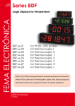
1
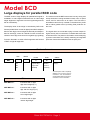
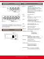
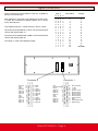
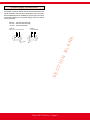
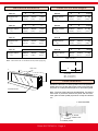
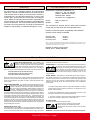
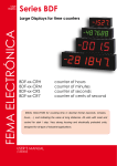
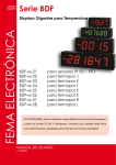
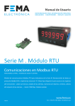
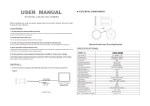
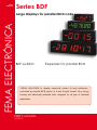
Series BDF
Large
Displays
FEMA ELECTRÓNICA
Large Displays for parallel BCD code
BDF-xx-BCD
Repeater for parallel BCD
IDEAL SOLUTION to display numerical values at long distances,
controlled by parallel BCD signal, in 4 and 6 digits format. Very strong
housing and electrically protected units, designed for all type of industrial
applications.
USER’S Manual
(1279r01)
User’s Manual BDF-xx-BCD
Model BCD
Large displays for parallel BCD code
The BDF series of large displays for parallel BCD signal is
available in 4 and 6 digits format with 57mm or 100mm digit
height. Digits are 7 segments in red color (optional green led,
ask for information).
The display value of each digit is controlled by BCD code.
Several parallel lines control all digits (lines ABCD independent for each digit). Control to light the decimal point independent for each digit, control for «HOLD» function to block the
refresh of each digit, and control for negative sign (polarity)
Function «BLANK» to switch-off all segments and function
«TEST» to light all segments.
The mechanical of the BDF instruments is a very strong and
sturdy aluminium housing anodized in black color, for panel
mount, and for wall mount as an option. The front lens is
antirreflexive and is firmly inserted on the aluminium profile
with a rubber gasket around, providing IP65 protection on
the front.
The signal wires are connected to plug-in screw clamps for
higher security of the connections, accessible at the rear side
of the instrument. The power is connected to a 3 terminal plug
(2 power connections and 1 earth) containing an integrated
protection fuse and an additional fuse as spare part.
Order reference
Model
Size
BDF
-
24
-24
-44
-26
-46
-
BCD
-BCD
Power
-
0
-0 (230 Vac)
-1 (115 Vac)
-6 (24 Vdc
isolated)
Others
Color
-
R
-Red
-Green
-
---65 (IP65)*
-(empty)
(check for
availability)
* the IP65 option uses a completely
different type of housing from the
indicated in this documentation.
Check the BDF IP65 housing documentation for more information.
Sizes
SIZE BDF-24 - Instrument with 4 digits
digit 57mm height (2,3’’)
SIZE BDF-44 - Instrument with 4 digits
digit 100 mm height (4,0’’)
SIZE BDF-26 .- Instrument with 6 digits
57mm digit height
SIZE BDF-46 .- Instrument with 6 digits
100mm digit height
FEMA ELECTRÓNICA - Page 2
User’s Manual BDF-xx-BCD
Front view
General specifications
Digit 1
Negative sign
Selectable decimal point
Digit 1
Negative sign
Selectable decimal point
Instruments BDF for parallel BCD code are available in 4 or
6 digits format. Digits are led type 7 segments, with decimal
point and negative sign.
Rear view
DISPLAY
4 or 6 digits in red color
7 segment Led
reading from -9999 to 9999 in 4 digits
reading from -999999 to 999999 in 6 digits
decimal point selectable
digit 57 mm (2,3”) in BDF-24 and BDF-26
digit 100 mm (4,0”) in BDF-44 and BDF-46
antirreflexive front filter
IP65 front protection
DATA
parallel BCD code
LOGIC
positive
logical level «1» >4,3 Vdc (max. 40 Vdc)
logical level «0» <1,1 Vdc.
HOLD
«HOLD» active in logical state «1».
independent for each digit
independent for the negative sign
in level «0» reading updates continuously
TEST
active in logical state «0».
lights all segments «-8.8.8.8.8.8.»
BLANK
active in logical state «0»
lights-off all segments
NEGATIVE
negative sign active in logical sate «0»
with independent «HOLD» control
CONSUMPTION BY CHANNEL
4 mA at 24 Vdc
1,5 mA at 12 Vdc
150 µA at 5 Vdc
Connector 2
ENVIRONMENTAL DATA
Working Temp. 0/+50ºC (32/122 ºF)
Storage Temp. -20/+85°C (-4/185ºF)
Rel. Humidity 0 to 85% non condensated
Connector 1 Power
(includes fuse)
HOUSING
extruded aluminium
anodized in black color
for panel mount (optional wall mount)
POWER SUPPLY
standard 230 Vac 50/60 Hz
(optional 115 Vac 50/60 Hz)
(optional 24 Vdc isolated)
CONSUMPTION
6 VA in series BDF-24 and BDF-26
12 VA in series BDF-44 and BDF-46
FEMA ELECTRÓNICA - Page 3
User’s Manual BDF-xx-BCD
Signal connections
Signal connections at male SUB-D connector available at
the rear of the instrument.
Digit X
D C B A
Each digit has 4 connection lines (ABCD) for its BCD code,
1 «Hold» line controlling the display update, and 1 control
for the decimal point.
The negative sign has 1 control line and 1 line for «Hold».
Connection lines identified as «+5Vdc» can be used as fixed
controls with logical state «1».
Connection lines identified with «GND» can be used as fixed
controls with logical state «0».
The «Digit 1» is the Least Significant Digit.
0
0
0
0
0
0
0
0
1
1
1
1
1
1
1
1
0
0
0
0
1
1
1
1
0
0
0
0
1
1
1
1
0
0
1
1
0
0
1
1
0
0
1
1
0
0
1
1
0
1
0
1
0
1
0
1
0
1
0
1
0
1
0
1
13
12
11
10
9
8
7
6
5
4
3
2
1
25
24
23
22
21
20
19
18
17
16
15
14
Blank
Test
Hold 4
Digit 4-D
Digit 4-C
Digit 4-B
Digit 4-A
Gnd
Hold 3
Digit 3-D
Digit 3-C
Digit 3-B
Display
0
1
2
3
4
5
6
7
8
9
10
11
12
13
14
15
0
1
2
3
4
5
6
7
8
9
A
b
C
d
E
«BLANK»
Connector 1
Connector 2
Digit 3-A
Gnd
Hold 2
Digit 2-D
Digit 2-C
Digit 2-B
Digit 2-A
Gnd
Hold 1
Digit 1-D
Digit 1-C
Digit 1-B
Digit 1-A
BCD Value
Gnd
13
Not connected12
Hold 6
11
Digit 6-D
10
Digit 6-C
9
Digit 6-B
8
Digit 6-A
7
Gnd
6
Hold 5
5
Digit 5-D
4
Digit 5-C
3
Digit 5-B
2
Digit 5-A
1
FEMA ELECTRÓNICA - Page 4
25
24
23
22
21
20
19
18
17
16
15
14
Not connected
+5 Vdc
+5 Vdc
Decimal 1 point
Decimal point 2
Decimal point 3
Decimal point 4
Decimal point 5
Decimal point 6
GND
Hold Negative sign
Negative sign
User’s Manual BDF-xx-BCD
Power supply connections
The power connector allows one terminal for earth and two
power terminals. Internal fuse is integrated on the connector
and an additional fuse is available as a spare part. The value
of the fuses depends on the power supply, and is according
to rule IEC127/2
230 Vac - 200 mA fuse time-lag
115 Vac - 400 mA fuse time-lag
24 Vdc - 350 mA fuse fast
Powered
230 Vac (115 Vac optional)
Powered
24 Vdc Isolated
-
AN
K
+
SE
CT
IO
N
BL
Fuse
FEMA ELECTRÓNICA - Page 5
User’s Manual BDF-xx-BCD
Mechanical dimensions
Size 24
4 digits 57mm (2’’)
Size 44
4 digits 100mm
(4’’)
Size 26
6 digits 57mm (2’’)
Size 46
6 digits 100mm
(4’’)
A
B
C
264mm 120mm (10,40’’)
(4,75’’)
A
B
B
384mm 120mm (15,12’’)
(4,75’’)
A
B
668mm 180mm (27,10’’)
(7,09’’)
4 digits 57mm (2’’)
4 digits 100mm (4’’)
(4,41’’)
D
6 digits 57mm (2’’)
Size 46
E
376mm 112mm (14,80’’)
(4,40’’)
(4,41’’)
E
472mm 172mm (18,58’’)
(6,77’’)
Size 26
112mm
112mm
D
(4,41’’)
E
256mm 112mm (10,07’’)
(4,40’’)
Size 44
112mm
C
D
(4,41’’)
C
Size 24
112mm
C
480mm 180mm (18,90’’)
(7,09’’)
A
Panel cut-out and weights
D
6 digits 100mm (4’’)
E
680mm 172mm (36,77’’)
(6,77’’)
weight
2.3 Kg
(5 lbs)
weight
5.0 Kg
(11 lbs)
weight
2.7 Kg
(6 lbs)
weight
5.7 Kg
(12,5 lbs)
PANEL CUT-OUT
Note .- add 27mm to the «C» dimension for the power supply plug
E
Rear cover
D
C
B
Panel width
Max. 14 mm (0,55’’)
Min. 2,5 mm (0,10’’)
Panel installation
A
Antirreflexive filter
Introduce instrument «1» into the panel cut-out and place the
fixation piece «3» on each side. Place screw «2» through fixation piece «3» until it presses the panel «4» and is firmly fixed.
Note - The front of the instrument is sealed IP65. To have the
same level of protection between the panel and the instrument, place a rubber profile (squared or round) as indicated
«5».
1- Instrument BDF
2- Screw
3- Fixation tool
4- Panel
5- Rubber profile
FEMA ELECTRÓNICA - Page 6
User’s Manual BDF-xx-BCD
Warranty
CE Declaration of conformity
All instruments are warranted against all manufacturing
defects for a period of 24 MONTHS from the shipment date.
This warranty does not apply in case of misuse, accident or
manipulation by non-authorized personnel. In case of malfunction get in contact with your local provider to arrange for
repair. Within the warranty period and after examination by
the manufacturer, the unit will be repaired or substituted when
found to be defective. The scope of this warranty is limited to
the repair cost of the instrument, not being the manufacturer
eligible for responsibility on additional damages or costs.
Manufacturer FEMA ELECTRÓNICA, S.A.
Altimira 14 - Pol. Ind. Santiga
E08210 - Barberà del Vallès
BARCELONA - SPAIN
www.fema.es - [email protected]
Series- Models
BDF-24 y BDF-44
BCD
The manufacturer declares that the instruments indicated
comply with the directives and rules indicated below.
Directive of electromagnetic compatibility 2004/108/CEE
Directive of low voltage 73/23/CEE
Security rules
Emission rules
Immunity rules
61010-1
50081-2
50082-1
NOTE .- During an electromagnetic disturbance (10V/m) it is permitted a worst case error of 1% of
the A/D range. The instrument will recover automatically its functionality when the disturbance stops,
without need of the operator to reset or restart.
Barberà del Vallès October 2009
Daniel Juncà - Quality Manager
Precautions on installation
INSTALLATION PRECAUTIONS.- The installation and
operation of this instrument must be done by qualified
operators. This instrument DOES NOT have power switch
and will start to operate as soon as the power supply is
connected. The instrument has an internal protection fuse, according to
IEC-127/2, and is located inside the power-supply connector. The values are
Fuse 200 mA Time Lag (for 230 Vac power)
Fuse 400 mA Time Lag (for 115 Vac power)
Fuse 350 mA Fast (for 24 Vdc power)
When the instrument is used to control machines or processes where the
personnel or the process can be damaged, the appropriate security elements must be added to the system in order to protect the operator and /
or the system.
SAFETY PRESCRIPTIONS.- This instrument has been designed and verified according to the UNE-20553 rules and is delivered in perfect
conditions of operation. This manual contains the adequate information for the electrical installation. Before starting operations for
connections, readjustment, substitution, maintenance, repair, etc,
the instrument must be unplugged from the power supply. The instrument
must be installed in places with good ventilation to avoid excessive heating,
and far from sources of electrical noise or magnetic field generators, such as
power relays, electrical motors, speed controls, etc... The instrument can not
be installed in open places. Do not use until the installation is finished. The
instrument is designed to be mounted on a metallic panel with the adequate
protections. DO NOT clean the front lens with abrasive products (such as
solvents, alcohol, etc) use a clean and water humid rag. Do not expose the
instrument to excessive moisture. DO NOT operate the unit in the presence
of flammable gases or fumes.
EXCITATION VOLTAGE Vexc.Instruments BDF-xx-32 and BDF-xx-36 supply an excitation voltage of 10 to
24 Vdc (50mA) to power transducers, available between terminals A and C.
Do NOT connect these terminals to an external power supply, permanent
damages may result on both instruments.
POWER SUPPLY .- Connect the Power Supply to the terminals indicated in
this manual. Verify that the voltage and frequency of the
power supply is according to the voltage and frequency
values indicated in the label attached to the unit. DO
NOT connect the instrument to power lines which are
overloaded, or power lines with loads working in ON/OFF cycles, or with
inductive loads.
SIGNAL WIRING .- Information to consider relating the wiring of the sensors, probes, transducers, etc. The wires can act as antennas and introduce
electrical noise from the environment into the signal wires, specially if the
wires are close to noise sources or electromagnetic sources. There are
several rules generally known which should be taken into consideration
for the wiring :
a.- DO NOT install impulse, control or signal wires together in the same
conduits as the wires connected to power lines, connected to CC or AC
engines, electromagnets, ...
b.- When using shielded wires, connect the shield to the common of the
instrument, and leave not-connected the probe side
c.- The wires of impulse, control and signal should be placed in places
far away from switches, transformers, control relays, etc...
IN CASE OF FIRE
1.- Disconnect the unit from the power supply.
2.- Give the alarm according to the local rules.
3.- Switch off all the air conditioning devices.
4.- Attack the fire with carbonic snow, do not use water
in any case.
WARNING : In closed areas do not use systems with vaporized liquids.
FEMA ELECTRÓNICA - Page 7
other products
Panel Meters
Standard 96x48mm
Panel Meters
Small 72x36 mm
Panel Meters
Miniature 48x24 mm
Large Displays
60 & 100 mm digit
Signal Converters
& Isolators
Panel Meters
Standard 96x48mm
www.fema.es
ELECTRONIC INSTRUMENTATION FOR INDUSTRY
FEMA ELECTRÓNICA, S.A.
Altimira 14 - Pol. Ind. Santiga
E08210 Barberà del Vallès
BARCELONA - SPAIN
Tel. (+34) 93.729.6004- www.fema.es
Fax (+34) 93.729.6003- [email protected]