1
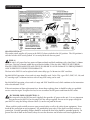
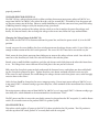
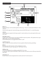
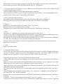
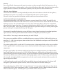
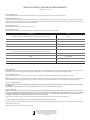
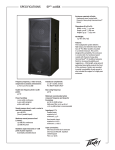
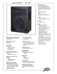
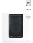
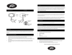
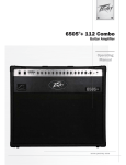
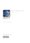
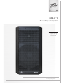
DM 112 ™ Powered Speaker System Operating Manual www.peavey.com FCC/ICES Compliancy Statement This device complies with Part 15 of the FCC rules and Industry Canada license‐exempt RSS Standard(s). Operation is subject to the following two conditions: (1) this device may not cause harmful interference, and (2) this device must accept any interference received, that may cause undesired operation. Le présent appareil est conforme aux CNR d’lndustrie Canada applicables aux appareils radio exempts de licence. L’exploitation est autorisée aux deux conditions suivantes: (1) I’appareil ne doit pas produire de brouillage, et (2) I’utilisateur de I’appareil doit accepter tout brouillage radioélectrique subi, même si le brouillage est susceptible d’en compromettre le fonctionnement. Warning: Changes or modifications to the equipment not approved by Peavey Electronics Corp. can void the user’s authority to use the equipment. Note – This equipment has been tested and found to comply with the limits for a Class B digital device, pursuant to Part 15 of the FCC Rules. These limits are designed to provide reasonable protection against harmful interference in a residential installation. This equipment generates, uses, and can radiate radio frequency energy and, if not installed and used in accordance with the instructions, may cause harmful interference to radio communications. However, there is no guarantee that interference will not occur in a particular installation. If this equipment does cause harmful interference to radio or television reception, which can be determined by turning the equipment off and on, the user is encouraged to try and correct the interference by one or more of the following measures. Reorient or relocate the receiving antenna. Increase the separation between the equipment and receiver. Connect the equipment into an outlet on a circuit different from that to which the receiver is connected. Consult the dealer or an experienced radio/TV technician for help. Caution The equipment complies with FCC radiation exposure limits set forth for an uncontrolled environment. ENGLISH Introduction Thank you for purchasing the powered Peavey® DM™ 112 powered speaker system. The DM™112 features a reliable bi-amped power section that provides a total of 660 Watts of peak available dynamic power with signal compression to prevent audible overload. The analog power amplifiers and linear power supply are coupled with a DSP based crossover and EQ. The LCD display and EQ presets along with other operating parameters are accessed via a one-knob selector. The DM™112 provides a balanced input via a combination jack that accepts balanced TRS 1/4 inch input as well as a balanced XLR input. There is a balanced Thru output via a Male XLR. There is an adjustable Gain control as well as a combination LED indicator that lights when power is on and changes color when the “soft-limiting” compression circuit is activated. Features * * * * * * * * * * * * * * * * * * Two-way bi-amplified analog amp powered speaker system 12” heavy-duty woofer DX™14 compression driver, with 1.4 inch titanium diaphragm 410 watts peak woofer power, 250 watts peak tweeter power DSP processing is 64 bit double-precision DSP I/O is at 96 kHz and 24 bits, with low-jitter, professional grade components Dynamic bass boost function Fan cooled for maximum reliability Patented Quadratic Throat Waveguide™ technology, 110 by 80 degree coverage Input is via a combo female XLR and 1/4” TRS phone jack with balanced input A Mic/Line switch provides for two different gain settings Thru output is via a male XLR jack Multiple Factory Preset EQ settings for the DSP crossover system User Preset EQ storage provisions allow storing custom presets for later recall Rugged plastic injection-molded trapezoidal enclosure Cabinet has dual rear corner angled sides for floor monitor use. Full-coverage perforated steel grille, with powder coat finish Pole mount molded-in for 1 3/8” diameter poles Description The DM™112 is a two-way sound reinforcement system based on a heavy-duty 12” woofer and a DX™14 titanium diaphragm dynamic compression driver mounted on a 110 by 80 degree coverage Quadratic Throat Waveguide™. It’s contemporary appearance coupled with exceptional performance offer an highly desirable combination. The light yet durable injection-molded plastic enclosure with molded-in stand mount cup eases portable use for live music or PA sound. The trapezoidal cabinet has three handles for ease of portability, and two extra angled sections on either side to allow use as a floor monitor. A full length black powder coated perforated steel grille provides system protection and a professional appearance. The heavy-duty 12” woofer has a warm punchy sound for plenty of bass. The DX™14 compression driver tweeter is coupled to a Quadratic Throat™ constant directivity waveguide, covered under US patent #6,059,069 with smooth, even response, low distortion and good high frequency dispersion. Advanced Digital Signal Processing (A.D.S.P.) provides the crossover function, driver limiting, as well as the driver EQ to enable the speaker system to provide an accurate and neutral sound for any type of music. The DSP processing uses 64 bit double-precision to insure accurate and transparent sound processing, and the input/ output sections use a 96 kHz sampling rate at 24 bits for maximum fidelity. Low-jitter clocking and professional grade components insure the sound quality is superb. An extremely flexible system of user presets and adjustments is implemented in the speaker system’s DSP computing core, and accessible via the rotary push-to-select knob and the LCD display. A total of 32 presets is available, with Factory presets made available, and room for user presets to be stored in memory, that are based off of the Factory presets as starting points. User adjustments include: bass and treble tone controls, polarity, and signal delay, all of which can be saved under a User preset that is named with up to 16 alpha-numeric characters. Thus, once a preferred set-up has been determined for a particular venue or typical use, these settings can be saved and recalled easily. The DM™112 speaker system power amplifiers providing the bi-amplification are low-distortion ultra-reliable fan-cooled units providing a total of 660W peak available dynamic power for the system. There is 410 W peak available dynamic power for the woofer, and 250 W peak available dynamic power for the tweeter. The power supply for both amps is a linear type for good reliability coupled with low cost. Both amplifiers feature sophisticated signal compression, which virtually eliminates audible power amplifier clipping. Cooling is provided via a low-noise fan, for reliable operation under any conditions. A built-in dynamic bass boost function provides the maximum amount of bass in such a small package. Input is via a combo female XLR and 1/4” TRS phone jack with balanced input to the DSP preamp/EQ electronics, and a Gain control. A Mic/Line switch allows for use of a microphone via the extra gain available when in the “Mic” position. A Thru output has a male XLR jack. This output allows linking of additional speaker systems, or feed of the signal to a powered subwoofer, etc. Applications The Peavey DM™112 has a variety of applications such as sound reinforcement, public address, side fill system, karaoke or musical playback. A typical signal source for the line-level inputs of the Peavey DM™112 would be a sound reinforcement mixing console (mixer) or the output from a CD player, MP3 player or tape deck. A dynamic microphone can be connected directly via the XLR input and used when the Mic/Line switch in placed into the “Mic” position as well. LOWER REAR PANEL BOTTOM OF REAR PANEL 1 4 2 3 ON-OFF SWITCH (1) This rocker switch supplies AC power to the DM™115 when switched to the ON position. The ON position is with the left side of the switch pushed FUSE (1)“in” or nearly flush with the rear panel. The unit is AC power line fuse protected from overloads and fault conditions with FUSE (2) a slow-blow 5 x 20mm 250V fuse. This fuse is located within the cap of the fuse The unit is AC power If line fuse protected fault BE conditions with a slow-blow 5 x 20mm holder. the fuse fails,from THEoverloads FUSE and MUST REPLACED WITH THE SAME 250V fuse. This fuse is located within the cap of the fuse holder. If the fuse fails, THE FUSE MUST BE RETYPE AND VALUE IN ORDER TO AVOID DAMAGE TO THE EQUIPMENT AND PLACED WITH THE SAME TYPE AND VALUE IN ORDER TO AVOID DAMAGE TO THE EQUIPMENT TO PREVENT VOIDING THE WARRANTY! AND TO PREVENT VOIDING THE WARRANTY! The fuse in the DM™112 can be replaced with a time-delay type 5 x 20 mm size The fuse in the DM™112 can be replaced with a time-delay type 5 x 20 mm size 250V rated fuse. 250V rated fuse. For 100-120VAC operation, a fuse rated at 4 amps should be used. In the USA, types GDC, GMC, 215, 218, and For fuserating rated amps should be used. In the USA, 477 cartridge-style 5 x100-120VAC 20 mm size fusesoperation, with a 4 ampa250V canatbe5used. types GDC, GMC, 215, 218, and 477 cartridge-style 5 x 20 mm size fuses with a For 220-240VAC5operation, a fuserating rated at 2 amps and 250V should be used, which conforms to the internationamp 250V can be used. al fuse classification “T2AL”. For 220-240VAC operation, a fuse rated at 2.5 amps and 250V should be used, If the unit continues to blow replacement fuses, do not keep replacing them, it should"T2.5 be taken to a qualified which conforms to the international fuse classification 15AL". service center for repair. To replace the fuse, be sure to remove the IEC power cord from the IEC socket. If the unit continues to blow replacement fuses, do not keep replacing them, it IEC POWER CORD CONNECTION (3) should a qualified center for repair. This receptacle is for be the taken IEC linetocord (supplied) service that provides AC power to the unit. It is very important that you ensure the DM™112 has the proper AC line voltage supplied. You can set the proper voltage for To the replace fuse,switch be sure remove the IECunit. power cord from the IEC socket. your DM™112 using Voltagethe Selector (3) ontothe rear panel of the Please read this guide carefully to ensure your personal safety as well as the safety of your equipment. Never break off the ground pin on any equipment. It is provided for your safety. If the outlet used does not have a IEC POWER CORD CONNECTION (2) ground pin, a suitable grounding adapter should be used and the third wire should be grounded properly. To This receptacle is always for thebeIEC cord (supplied) that provides AC power prevent the risk of shock or fire hazard, sure line that the mixer and all other associated equipment are to the unit. It is very important that you ensure the DM™112 has the proper AC line properly grounded. VOLTAGE SELECTOR SWITCH (4) The DM™112 has a voltage selector switch to allow switching between an input power voltage of 120VAC to a range from 220VAC to 240VAC, all at either 50 or 60 cycles per second (Hz). It should be set to the proper voltage for your country out of the box. However, world conditions are such that some areas have power line voltages differing from the voltage used by the majority of any given locale. Be sure to check the position of the voltage selector switch to see that it matches the power line voltage used locally. If it does not match, then to change the voltage to the correct one, follow the steps outlined below. Changing the Voltage Range of the DM™112 First, make sure the DM™112 is disconnected from the power line, and that the power switch (4) is in the OFF position. Second, unscrew the screws holding the clear switch protector on the voltage selector switch (3) just a little, just enough to allow rotation of the clear switch protector. The screws DO NOT need to be unscrewed very far. Third, rotate the clear plastic protector about 90 degrees to uncover the voltage selector switch. One side of the cover has a slot; the other just a hole. The side with the hole is the side that pivots. Fourth, using a small flat blade screwdriver, push the red selector switch slide plate to the other side from where it was. The voltage that is now visible on the red slide plate is the one you have selected. Fifth, rotate the clear plastic protector back underneath the loosened screws, and tighten one down while holding the clear plastic protector in place. Tighten the other screw down, and make sure both screws are tight. If the screws are over-tightened, this could damage the voltage selector switch clear plastic cover, so do not apply excessive force to the screws! Sixth, the fuse should be changed to the correct amperage rating. For an input power voltage of 120VAC, use a 4 amp rated, 250V 5 x 20 mm cartridge type time-delay fuse, which conforms to the international fuse classification “T4AL”. For an input power voltage range of from 220VAC to 240VAC, use a 2 amp rated, 250V 5 x 20 mm cartridge type time-delay fuse, which conforms to the international fuse classification “T2AL”. The IEC power cord that is correct for your locale can now be plugged into the IEC receptacle (2), and the Power switch (4) activated to turn on the powered DM™112 speaker system. ON-OFF SWITCH (4) This rocker switch supplies AC power to the DM™112 when switched to the ON position. The ON position is with the top side of the switch pushed “in” or nearly flush with the rear panel. UPPER REAR PANEL 11 6 12 7 8 9 5 10 INPUT (5) The line-level input is of the medium impedance balanced type. The jack is a combo female XLR and 1/4" TRS connector. Sensitivity of this input is 0.39 volts for full output, when the MIC/LINE switch (7) is in the LINE position GAIN (6) Controls the gain or output level of the input signal. It is used to directly set the system output level for a given input signal. MIC/LINE switch (7) Switches between LINE level gain (out position) and MIC level gain (in position). MIC position increases gain 20 dB to allow use of most dynamic microphones. NOTE: Phantom power is not supplied on the INPUT (5) jacks Gnd LIFT switch (8) Allows the shield to be disconnected from the chassis ground to alleviate hum from ground loops LED (9) Illuminates green when the power switch is on and power is present It turns Red when the power amp engages the “Soft Limiting” circuitry. THRU jack (10) This jack is intended for the use of linking multiple DM™112’s in a line or to provide a feed to a powered subwoofer, or other electronics that needs to receive a full range version of the input signal. LCD Display (11) Provides a menu read-out manipulated and activated by the Push-To-Select button (12) UPPER REAR PANEL Push-To-Select button (12) Rotary knob that allow the user to select and choose menu options on the LCD display screen (11). Pushing the button in till it detents makes a menu choice. OPERATING INSTRUCTIONS Cautions The unit must be disconnected from the AC power source before any work is done on it. Refer all servicing to qualified service personnel. The back plate can become hot to the touch. Do not block or cover the fan or the exhaust louvers from ventilation. There must be a minimum of 4” of space behind the fan. Do not allow the airflow to be become blocked by objects such as curtains or drapes, thermal building insulation, etc. It is recommended that the rear of the DM™112 not be placed in a closed space or a space that has no fresh, cool airflow. Be sure to keep the microphone away from the front of the speaker after connecting it to the input, and while setting the microphone level, or very loud feedback will occur! Damage to the system is likely if this occurs! DO NOT connect the inputs of the DM™112 to the output of a power amplifier. The inputs are meant to be driven from a line-level strength signal. DO NOT remove the protective metal grille. WARNING! The DM™112 is very efficient and powerful! This sound system can permanently damage hearing! Use extreme care setting the overall maximum loudness! The apparent sound level of the DM™112 can be deceiving due to its clear, clean sound output. The lack of distortion or obvious distress can make the sound level seem much lower than it actually is. This system is capable of SPL in excess of 124 dB at 1 M from the speaker! Connecting AC Power To The DM™112 The DM™112 comes with an 6-foot IEC connection AC power cord. If you are using an extension cord or power strip with this powered speaker, make sure it is of good quality and of a sufficient current capacity to maintain safety and maximize the power output capability of the DM™112. For maximum undistorted output, do not connect any other device to the same extension cord that the DM™112 is connected to. Do not exceed the rated current capacity of the extension cord with the sum total of all units connected to it. When first plugging in the AC cord, make sure the power switch is in the Off position, and then turn it On only once the power cord has been connected. Built-in muting will engage when the proper sequence of steps is taken. Use of the DM™112 with a Speaker Stand The DM™112 has a stand mount cup molded-in so that the system can be stand mounted on a standard 1 3/8” (36mm) diameter stand pole. When using stands or poles, be sure to follow these precautions: A. Check the stand or pole specs to make sure that it can support the weight of the DM™112 (35 lbs./15.9 kg), and observe all safety precautions stated by the stand manufacturer, including the maximum height the stand is rated for. B. Always place the stand on a flat, level and stable surface, and be sure to fully extend the stand legs as per the stand manufacturer’s instructions. C. Try to make sure that the stand legs are oriented for the least danger of tripping to those in the vicinity of the stand. Never block a doorway or hallway with the legs of a stand. D. Try to route cables so that people will not trip over them, or tip the speaker over. Use of duct tape, cable channels or guards, or other appropriate tie-down/cover –up devices should be carefully considered and implemented. E. When installing or de-installing the speaker on the stand, it is a good practice to have a helper if possible, it can be hard to “thread the needle” and mate the stand cup to the stand pole while holding the DM™112 speaker system at arm’s length. It is also helpful if someone holds the speaker stand and pole down while the DM™112 is removed from the stand pole, this prevents the DM™112 from pulling the pole up with it. F. When using stands outdoors, never attach banners or flags to the stands or the DM™112 speaker system, strong winds may cause the speaker to blow over. If there is a possibility of windy conditions, then it may be prudent to consider weighting or locking down the stand legs to prevent the DM™112 speaker system from being blown over. Connecting a Signal to the DM™112 There are a variety of ways to input a signal to the DM™112. The input (5) provides either a balanced mic- or line-level input, allowing the use of a 1/4" TRS (ring-tip-sleeve) type phone plug or a male XLR plug. Do not connect cables to the jacks while the unit is ON and the Level knob is turned up! While a standard single-ended 1/4" phone plug-equipped cable will work well and the balanced input circuitry will provide some interference rejection, a balanced cable using either the balanced TRS 1/4" phone plug or the XLR plug will provide superior interference rejection and performance. Sometimes, with difficult interference problems, it will be helpful to lift the shield ground ( Pin #1 of an XLR) of a balanced cable at the DM™112 end. Check any input changes carefully, always turning the Level control down before plugging and unplugging cables, or lifting the ground. Use of high quality, premium cables is recommended for the DM™112, as these usually have better shielding and materials and will provide greater long-term reliability. The best option is a shielded balanced cable no longer than necessary to reach the DM™112. It is usually a good idea to leave some slack at the input to the DM™112 and also to tape the cables down or run them under a cable guard to avoid anyone tripping over them or pulling the DM™112 over when stand mounted.. Level Control Adjustment The DM™112 is equipped with a Gain control (6) on the input to facilitate use in many different applications. With the Gain control adjusted fully clockwise, gain is at maximum and the input sensitivity is 0.39 V RMS for full-rated output with the line level position of the Mic/Line Switch (7). When driving the DM™112 from a mixer, it may be advantageous to reduce the input sensitivity by turning the Gain control to the halfway point. The DM™112 will now more closely match a typical power amp. If the mixing board indicates clipping of its output signals, then all of the DM™112 power capability is not being utilized cleanly. Clipping the signal before it gets to the DM™112 is not optimal. Reduce the mixer output level and turn up the Gain control on the DM™112. The amplifiers in the DM™112 are equipped with “Soft Limiting” circuitry and the LED indicator will show when DM™112 DDT™ has engaged. If the sound seems heavily compressed, check these indicators; if it is blinking RED more than occasionally, then the drive level from the mixer (or the Gain control on the DM™112) needs to be reduced. When first turning on the sound system, switch on all upstream electronics first, then the DM™112 with its Gain control fully counterclockwise (all the way down). Begin checking levels with the mixer output level controls all the way down, and bring them up slowly with the DM™112 Gain control set to the desired setting (one-third way up recommended to start). It is not good practice to turn the Gain control on the DM™112 all the way up and then try to control level only from the mixer, this approach would tend to pick up excess noise. Best practice would be to run a “hot” signal from the mixer down the cable to the DM™112, and then turn the DM™112 Gain control up only as much as necessary to reach full desired output. With this approach, it is necessary to verify the mixer output is not clipping. Disconnecting AC Power to the DM™112 We recommend that the Power switch (3) be used to turn the unit off first, and then the AC power cord can be removed, this minimizes stress to the power amplifiers and the transducers from turn-off transients. The power switch has an arc suppression capacitor to help during turn-off, and tends to make a clean disconnect from the AC power, while the power cord IEC connector can make intermittent contact before finally becoming fully disconnected, e.g., as when wiggling the cord. EQ Preset Management – RECALL and SAVE Presets Upon turn-on, the DM™112 loads the DSP firmware into memory, and after about 5 seconds, loads the last previously used preset, including any custom changes, into the DSP. The message " Recall preset " appears in the LCD display along the top line, while the second line displays the name of the preset loaded. These will display for approximately 16 to 25 seconds, then if no action is taken, the model designator and number will display on the top line, and the currently loaded preset will display on the second line. If the user desires to go to one of the other menu choices while the message " Recall preset " appears in the LCD display, then simply rotate the "Push-to-Select" knob to access the other menu choices. Those choices are: 1. Recall Preset 2. Delay 3. Polarity 4. Bass 5. Treble 6. Save Preset Once the desired menu choice is displayed, push in the "Push-to-Select" knob. If the default LCD message display is present (e.g. DM 112 and 01: EDM ), then push in the "Push-to-Select" knob to bring up the menu, which will display the first choice of " Recall preset ". 1. If you have selected " Recall preset " to select a different preset, then push the "Push-to-Select" knob to be able to rotate through the preset choices. An arrow symbol will appear at the left hand margin on the second line. You can now rotate the "Push-to-Select" knob to access the other preset choices. Once the desired Preset is displayed, push the "Push-to-Select" knob in and it will be loaded 2 Delay - adjustable from 0 to 15 msec. Rotate knob to adjust the delay amount, push to select the chosen delay amount and engage it. The delay will be stored, and the menu will revert back to the " Recall Preset " message line. 3. Polarity Rotate the "Push-to-Select" knob to select either " Direct " or " Inverse ". Push the "Push-to-Select" knob in to save the change. The Polarity will be stored, and the menu will revert back to the " Recall Preset " message line. 4. Bass This allows a +/- 6 dB boost or cut tied to a hinge point set by the current preset. Each preset has a different hinge point for the Bass and Treble, so experimentation with the different presets in conjunction with the tone controls will yield a wide variety of available EQ curves. Rotate the "Push-to-Select" knob to choose the amount of boost or cut in 1/2 dB increments from + 6 dB down to - 6 dB. These tone changes occur on top of an existing factory EQ preset. Push the "Push-to-Select" knob in, and the tone setting will be stored, and the menu will revert back to the " Recall Preset " message line. 5. Treble Same as for the Bass menu. 6. Saving Your Menu Changes Once all menu items have been selected or changed, and the LCD screen has reverted to the menu default message, the " Recall Preset " option, you can then rotate the knob to select the “ Save Preset “ option, and save the modified set of preset parameters using a name of your choice (limit 16 characters total). If you selected " Save Preset ", then the LCD display now shows the label " EDIT NAME " on the first line and a blinking cursor at the first position of the naming field on the 2nd line in the LCD. Rotate the "Push-to-Select" knob to select the alphanumeric character desired. Up to 16 characters can be used for the name. Push the "Push-to-Select" knob to enter the first selected character. After the first character is entered, the blinking cursor will move to the next character in the line, where up to 16 alphanumeric characters can be entered. The "Push-to-Select" knob will have to be pushed 16 times to get to the end of this portion of the " Save Preset " process. Once all the characters are entered, a message asking “ Save, are you sure? ” will display, rotate the "Push-to-Select" knob till the “ Yes ” answer is bracketed. Push the "Push-to-Select" knob and the preset will be stored, and the menu will revert back to the " Save Preset " menu line. If you select “ Cancel ”, then the menu will revert to the " Save Preset " option. At that point, you can rotate the "Push-to-Select" knob and select another menu choice, or start the “ Save Preset ” process over again. You can save a Factory Preset without any changes, and just re-name it, but it must be saved in one of the User Preset locations (11 thru 32). The Factory Presets in locations 01 through 10 are permanently saved at those locations The saved preset is one of the Factory Presets with the added menu item changes on top of that original factory preset, and what is saved is the current set of DSP parameters. These added menu item changes would include: Delay, Polarity, Bass and Treble changes. If no action is taken for approximately 16 to 25 seconds, then the model designator and number will display on the top line, and the currently loaded preset on the second line. To access the menu items 1 through 6, you will need to push the "Push-to-Select" knob in. Note that if the changes to a Factory Preset are not saved using the full procedure as outlined in step 6, then even though the DM™112 will retain the preset and changes for use with the next power-up, if ANY Preset is recalled, then those settings that were in the unit at that time will be lost. If the LCD menu locks up or otherwise becomes non-responsive, try waiting for about 30 seconds, and see if it becomes responsive again. However, if it does not, then power the unit off, wait 10 seconds, and turn it back on again to re-start the unit from scratch. This will reset the DSP menu. Note that any actions taken to alter the menu settings for the Delay, Polarity, Bass or Treble before those changes were properly saved will be lost, and you will need to start over again. TROUBLESHOOTING No Output at All First, make sure the unit has AC power and is turned ON. Make sure the LED on the power amp module is illuminated. If not, make certain the ON/OFF switch (4) is in the ON position and check the IEC power cord connection (2) by ensuring it is fully engaged and seated. Make certain the AC line cord is plugged into a working AC outlet. Finally, check the fuse (1). (See the Rear Panel: FUSE section, for safety instructions.) Once assured your unit is getting AC power, check that the DM™112 is getting a signal. Temporarily disconnect the cable running to its inputs and connect it to some other device capable of reproducing the signal (i.e., a power amp and speaker). If this produces a signal, make sure that all Level controls being used have been turned up to a satisfactory level (one-third to halfway). If the DM™112 has been subjected to direct sunlight or excessive heat, the built-in thermal protection may have been triggered. If so, turn off the DM™112 and let it cool for a sufficient amount of time. If there is still no output, contact your authorized Peavey dealer or the Peavey International Service Center. Hum or Buzz If the DM™112 is producing a hum or buzz, this can be AC outlet related. Try plugging the DM™112 into a different AC outlet. Sometimes, if a different circuit (breaker) is used for the mixer and for the DM™112, it can cause hum problems. Unless it is not practical, it is best to use the same wall outlet (breaker) to supply power to both the mixer and the powered speaker. Ensure that shielded cables have been used to route the signal to the DM™112’s input. If speaker cables with 1/4" plugs are used as input cables instead of shielded cables, they will be prone to hum or buzz. Hum may be ground loop related. It may be helpful to lift the shield ground (Pin #1) on a balanced cable at the DM™112 end. Check any input changes carefully by first turning down the Level control, before plugging and unplugging cables, or lifting the shield ground at the speaker end. Check to make sure light dimmers are not on the same circuit as the DM™112, the mixer or any source devices. If light dimmers are used, then it may be necessary to turn them full ON or full OFF to eliminate or reduce hum. This is a typical AC wiring/light dimmer interference problem, not a design flaw of the DM™112. The third wire (ground plug) on the AC plug should NEVER be removed or broken off, as this is a potential safety hazard. Distorted or Fuzzy Sound First, ensure the mixer (signal source) is not clipping or being overdriven. Make sure the Level (6) control on the DM™112 has not been set too low. Check that the input plug is fully seated in the input jack on the rear panel of the DM™112. Ensure that a power amp has not been plugged into the input jack of the DM™112. If an extension cord is being used to provide the AC power to the unit, insure that it is of sufficient current capacity and that it is not also being used to supply power to any other device. The DM™112 has built-in EQ to smooth and extend the natural response of the speakers. If excessive additional bass boost or HF boost have been added externally to the DM™112, it could cause premature overload at high SPL. Reduce the amount of any external (mixer, rack) EQ and see if that clears up the distortion. Finally, realize that even though the DM™112 is a powerful and high output unit, it does ultimately have limits, and it may need additional powered units (or a subwoofer) to provide enough sound output or coverage. In this case, try turning the mixer levels down a little to see if that clears things up. If, after checking all the things listed to check and anything else you can think of to check safely, and the system still exhibits problems, carefully note all conditions and check with your Peavey dealer for advice. Care and Maintenance Your DM™112 is a sturdy and durable product and will provide years of reliable use if properly cared for. Use common sense and read the safety warnings to avoid hazardous operating conditions. The unit must be disconnected from the AC power source before any work is done on it. Refer all servicing to qualified service personnel. Sunlight/Heat Avoid prolonged exposure to direct sunlight, as this may cause the unit to overheat and thermally shut off. Excessively hot operating conditions can also cause a thermal shutdown. Do not store in extremely hot or cold conditions or extremely high humidity. Always allow unit to come to room temperature before use. Cleaning Never clean the DM™112 while plugged in or turned ON! When the unit has been fully disconnected from AC power sources, use a dry cloth to remove soil or other dirt. Never use strong solvents on the DM™112, as they could damage the cabinet. Do not allow ANY fluids to drip inside the DM™112. Touchup For an overall finish enhancement and protective coating, use gloves to apply a plastic finish protector, such as Armor-All® protectant or a similar product, to the surface of the plastic cabinet only. Note that the cabinet will be slippery after these treatments; rub them down vigorously with a dry, lint-free cloth to minimize this. Check for Secure Hardware After the first few months of use and periodically thereafter, check the hardware of the DM™112 for tightness, including the rear panel screws and the screws that hold the baffle and rear cabinet together. The unit is subject to a great deal of vibration, and this could cause them to loosen with use. Architectural and Engineering Specifications The powered loudspeaker system shall have a frequency response from 68 Hz to 19 kHz. The peak SPL with inaudible distortion shall reach 124 dB with music as a source, when measured at a distance of 1M and driven to full output capacity. The system shall utilize a 12” heavy-duty woofer and a Peavey® DX™14 1.4” titanium diaphragm dynamic compression driver. The nominal radiation pattern shall be 110° in the horizontal plane, and 80° in the vertical plane. Axis of the vertical main polar lobe is angled down 10 degrees, resulting in the angular pattern with respect to straight ahead being +30, -50 degrees. The powered, bi-amplified loudspeaker system shall have an input channel consisting of a medium impedance input connector consisting of one combo female XLR and 1/4” TRS phone jack on the rear panel. There shall be a Thru (output) connector consisting of a male XLR jack. The system power amplifiers shall have an unfiltered frequency response of 20 Hz to 20 kHz which deviates no more than +1, -3 dB up to rated power, hum and noise better than 90 dB below rated power, and THD and IMD typically of less than 0.7%. The woofer amplifier shall be capable of 125W continuous into a 4 ohm nominal load, and the tweeter amplifier shall be capable of 80 W continuous output into a 8 ohm load, and both shall incorporate independent signal compression. The input signal shall be electronically divided into high frequencies and low frequencies by a Linkwitz-Riley fourth order slope line-level crossover at 3.1 kHz. The low frequencies shall be processed to provide bass boost, subsonic filtering and overall response shaping, and the high frequencies shall be equalized for response-shaping. The enclosure shall be constructed of injection-molded polypropylene with a UL flame rating, and reinforcing ribs internally. A handgrip shall be incorporated on each side near the woofer and towards the rear, and on the top rear edge of the cabinet. A full-length powder-coated metal grille shall be provided for horn and woofer protection. The cabinet shall incorporate a pole mount for speaker stand use, four tall sturdy rubber feet for floor standing use. The outside dimensions shall be: 25.30” (64.3 cm) tall x 14.38” (36.6 cm) wide x 14.00” (35.6 cm) deep, and the weight shall be 35 lbs. Power requirements shall be: 170 Watts nominal, 120 VAC, 50/60 Hz Domestic and 220240 VAC, 50/60 Hz (Export). The loudspeaker system shall be called a Peavey® DM™112 SPECIFICATIONS Frequency Response: 68 Hz to 19 kHz, +/- 6 dB, anechoic environment Usable Low Frequency limit (-10 dB point anechoic): 55 Hz Nominal sensitivity (1W @1M, swept sine input in anechoic environment): 96 dB (average) Maximum Sound Pressure Level (1 meter): 124 dB SPL peak with music Radiation Angle measured at -6 dB point of polar response: Nominal: 110 degrees horizontal X 80 degrees vertical (Axis of the vertical main polar lobe is angled down 10 degrees, resulting in the angular pattern with respect to straight ahead being +30, -50 degrees) Transducer Complement: Heavy-duty 12” woofer with 1 1/2” voice coil & 32 oz. magnet DX™14 1.4” titanium diaphragm dynamic compression driver Box Tuning Frequency: 52 Hz Electroacoustic crossover frequency: 3,100 Hz Crossover type: Internal Electronic DSP based two-way crossover with driver EQ, level matching, bass boost, limiting and subsonic filtering. Crossover Slopes: Linkwitz-Riley 24 dB/octave (4th order) low pass, 24dB/octave (4th order) high pass, both with driver EQ incorporated. Input Connections: One combo female XLR / 1/4" phone jack providing balanced line-level operation from the 1 / 4” jack section, and the XLR section. Output Connections: One male XLR jack. The Thru jack is intended for the use of linking multiple DM™112‘s in a line or to provide a feed to a powered subwoofer, or other electronics that needs to receive a full range version of the input signal. Enclosure Materials & Finish: Black polypropylene plastic with textured surface, black powder-coated perforated full-coverage grille. Mounting provisions: Four rubber feet provide vibration free floor or stage use, and a molded-in stand mounting cup is on the bottom. Unit is not designed to be flown overhead Overall Dimensions ( H x W x D ) 25.3”H x 14.38”W x 14.00”D 643 mm x 366 mm x 356 mm Weight: 35 lbs. (15.9 kg) ELECTRONICS AND AMPLIFIER SPECIFICATIONS: Internal power amplifiers (@120 VAC line): Total of 660 watts peak dynamic power Woofer - 410 watts peak dynamic power Continuous Power: 125 watts @ less than 1% distortion Tweeter - 250 watts peak dynamic power Continuous Power: 80 watts @ less than 1% distortion. Electronic Input Impedance (Nominal): Line: 10 k ohms balanced (XLR or 1/4") Mic: 10 k ohms balanced (XLR) No phantom power available. Input Sensitivity for Full Output (Level full CW): 0.39 V RMS (Switch in LINE position) Input Overload Point (Switch in LINE position): +17 dBV Infrasonic filter protection: 36 dB/octave roll-off Nominal Amplifier Frequency Response: +1, -3 dB from 20 Hz to 20 kHz Hum and Noise: Greater than 90 dB below rated power THD and IM: Typically less than 0.7 % Power requirements of Peavey DM™112 System: Nominal 170 Watts, 120 VAC 60 Hz Fuse Type For 120 VAC USE: International fuse classification T4AL 250V. In the USA, types GDC, GMC, 215, 218, and 477 cartridge-style 5 x 20 mm size fuses with a 4 amp 250V rating can be used. For 220-240VAC USE: International fuse classification T2AL 250V . This is a cartridge style 5 x 20 mm size time-delay fuse with a 2 amp 250V rating. PEAVEY ELECTRONICS CORPORATION LIMITED WARRANTY Effective Date: 11/01/2011 What This Warranty Covers Your Peavey Warranty covers defects in material and workmanship in Peavey products purchased and serviced in the U.S.A. and Canada. What This Warranty Does Not Cover The Warranty does not cover: (1) damage caused by accident, misuse, abuse, improper installation or operation, rental, product modification or neglect; (2) damage occurring during shipment; (3) damage caused by repair or service performed by persons not authorized by Peavey; (4) products on which the serial number has been altered, defaced or removed; (5) products not purchased from an Authorized Peavey Dealer. Who This Warranty Protects This Warranty protects only the original purchaser of the product. How Long This Warranty Lasts The Warranty begins on the date of purchase by the original retail purchaser. The duration of the Warranty is as follows: Product Category Duration Guitars/Basses, Amplifiers, Preamplifiers, Mixers, Electronic Crossovers and Equalizers 2 years Drums 2 years Enclosures 3 years Digital Effect Devices and Keyboards and MIDI Controllers 1 years Microphones 2 years Speaker Components (incl. Speakers, Baskets, Drivers, Diaphragm Replacement Kits and Passive Crossovers) 1 year Tubes and Meters 90 Days Cables Limited Lifetime AmpKit Link, Xport, Rockmaster Series, Strum’n Fun, RetroFire, GT & BT Series Amps 1 year Marvel Jr. Guitar 90 Days What Peavey Will Do We will repair or replace (at Peavey’s discretion) products covered by Warranty at no charge for labor or materials. If the product or component must be shipped to Peavey for Warranty service, the consumer must pay initial shipping charges. If the repairs are covered by Warranty, Peavey will pay the return shipping charges. How To Get Warranty Service (1) Take the defective item and your sales receipt or other proof of date of purchase to your Authorized Peavey Dealer or Authorized Peavey Service Center. OR (2) Ship the defective item, prepaid, to Peavey Electronics Corporation, International Service Center, 412 Highway 11 & 80 East, Meridian, MS 39301. Include a detailed description of the problem, together with a copy of your sales receipt or other proof of date of purchase as evidence of Warranty coverage. Also provide a complete return address. Limitation of Implied Warranties ANY IMPLIED WARRANTIES, INCLUDING WARRANTIES OF MERCHANTABILITY AND FITNESS FOR A PARTICULAR PURPOSE, ARE LIMITED IN DURATION TO THE LENGTH OF THIS WARRANTY. Some states do not allow limitations on how long an implied Warranty lasts, so the above limitation may not apply to you. Exclusions of Damages PEAVEY’S LIABILITY FOR ANY DEFECTIVE PRODUCT IS LIMITED TO THE REPAIR OR REPLACEMENT OF THE PRODUCT, AT PEAVEY’S OPTION. IF WE ELECT TO REPLACE THE PRODUCT, THE REPLACEMENT MAY BE A RECONDITIONED UNIT. PEAVEY SHALL NOT BE LIABLE FOR DAMAGES BASED ON INCONVENIENCE, LOSS OF USE, LOST PROFITS, LOST SAVINGS, DAMAGE TO ANY OTHER EQUIPMENT OR OTHER ITEMS AT THE SITE OF USE, OR ANY OTHER DAMAGES WHETHER INCIDENTAL, CONSEQUENTIAL OR OTHERWISE, EVEN IF PEAVEY HAS BEEN ADVISED OF THE POSSIBILITY OF SUCH DAMAGES. Some states do not allow the exclusion or limitation of incidental or consequential damages, so the above limitation may not apply to you. This Warranty gives you specific legal rights, and you may also have other rights which vary from state to state. If you have any questions about this Warranty or services received or if you need assistance in locating an Authorized Service Center, please contact the Peavey International Service Center at (601) 483-5365. Features and specifications are subject to change without notice. Logo referenced in Directive 2002/96/EC Annex IV (OJ(L)37/38,13.02.03 and defined in EN 50419: 2005 The bar is the symbol for marking of new waste and is applied only to equipment manufactured after 13 August 2005 U.S. customer warranty registration. Logo referenced in Directive 2002/96/EC Annex IV (OJ(L)37/38,13.02.03 and defined in EN 50419: 2005 The bar is the symbol for marking of new waste and is applied only to equipment manufactured after 13 August 2005 FROM: Place Postage Here Peavey Electronics Corporation Attn: Warranty Department PO Box 1150 Meridian, Ms 39305