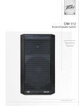
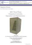
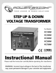
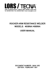
1
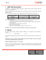
UMBPS15N
BPS1-5N
High Voltage Bench Power Supply
This document supersedes all previous specifications. Photek accept no responsibility for
damage incurred if the customer does not follow the procedures outlined in this manual.
Photek Ltd
26 Castleham Road
St Leonards-on-Sea
East Sussex
United Kingdom
TN38 9NS
Telephone
Facsimile
E-mail:
+44 1424 850555
+44 1424 850051
[email protected]
Issue 5
13th August 2012
1
Manual No
Issue:
Date:
Author:
UMBPS15N
5
13-8-2012
P Simpson
UMBPS15N
Contents
1
BPS1-5N DESCRIPTION
3
2
SAFETY:-
3
3
OPERATING INSTRUCTIONS
4
4
FRONT PANEL DESCRIPTION
5
4.1
Power Switch
5
4.2
Interlocks 1 & 2 Switches
5
4.3
HT On Switch
6
4.4
Adjust Voltage Control
6
4.5
Display
6
5
REAR PANEL DESCRIPTION
7
5.1
IEC Mains Inlet
7
5.2
HT Output Connector
7
5.3
GND Terminal
8
5.4
Interlock & Power Output
8
5.5
Interlock Inputs
9
5.6
DC Power Output Fuses
9
6
HIGH VOLTAGE CONNECTION NOTES:-
10
7
SPECIFICATIONS
11
8
ITEMS SUPPLIED
12
2
Manual No
Issue:
Date:
Author:
UMBPS15N
5
13-8-2012
P Simpson
UMBPS15N
1 BPS1-5N Description
The BPS1 is a. mains powered high voltage power supply unit with a universal input which will
operate between 90-260V a.c..
There is one high voltage output which may be used to power a detector fitted with a potential
divider network.
This unit contains one negative power supply module with the following specifications:High Voltage Output
Maximum
-5kV
Output Current Maximum
Full Load Ripple
1mA
500mV
Features of this unit are:• Variable high voltage output with 10V resolution display (±5V) .
• dv/dt power up feature to control the output with ‘ramp up’ function when the unit is
first switched on.
• Output Short Circuit and Flash-over protection.
• Two user interlock functions.
• Three fused low voltage power outputs (+12V,+5V,-12V)
The BPS-1 does not provide any image acquisition or image processing functions.
2 Safety:The high voltage module contained within the BPS-1 has a maximum current capability as
follows:• V1
(-5kV module)
1mA
The maximum output energy that can be delivered by this module is limited to 4 joules for user
safety,
Warning:- If a large capacitive load is connected across the output, the energy stored by
this external capacitor may exceed this limit.
Energy Stored By Capacitor = ½ CV2 joules
In order to avoid any corona discharge: - Under no circumstances should a high voltage output
be run at a voltage higher than 5kV in air without some insulation material encapsulating the
high voltage connection.
3
Manual No
Issue:
Date:
Author:
UMBPS15N
5
13-8-2012
P Simpson
UMBPS15N
3 Operating Instructions
1. The BPS1 high voltage output must be connected to the device before application of power
to this unit.
2. Ensure the HT On switch is off (the pushbutton switch protrudes from the front panel when
the HT is off).
3. Set the Adjust Voltage potentiometer to minimum before applying power to this unit
(minimum output voltage is when the potentiometer control is fully counter-clockwise).
4. The power may now be turned ‘On’.
5. Enable any interlocks required and ensure that they are satisfied.
6. The high voltage may now be turned on by pressing the ‘HT On’ switch, the high voltage
will then increase linearly over approximately 6 seconds. (If either or both interlocks are
utilised these must be satisfied before the high voltage will enable).
7. The Adjust Voltage potentiometer may now be slowly rotated clockwise to the desired
output voltage. The set value can be monitored on the display.
8. The unit may now be operated at this level without further adjustment of the Adjust Voltage
control unless a gain modification is required.
9. To power down the high voltage the ‘HT On’ switch may be pressed. The high voltage
output will switch off immediately.
10. Set the Adjust Voltage potentiometer to minimum before the power to the BPS1 is turned
‘Off’.
4
Manual No
Issue:
Date:
Author:
UMBPS15N
5
13-8-2012
P Simpson
UMBPS15N
4 Front Panel Description
The front panel of the BPS1 is illustrated below: -
4.1 Power Switch
The illuminated power on/off switch will illuminate ‘Red’ when the unit is switched ‘On’.
The neon illuminator in this switch is driven directly from the input mains supply and if the
input mains supply voltage is below 100V ac this neon may appear to flash, this in no way
affects the operation of the BPS unit.
4.2 Interlocks 1 & 2 Switches
These are 2 latching pushbutton switches which allow the user to enable the 2 interlock inputs
which may be utilised by the customer to provide safety over-ride functions for the system.
Interlocks can be enabled individually or together by depressing the required interlocks’
pushbutton switch. When an interlock is enabled the interlock switch will illuminate red. If
either interlock is enabled but not satisfied the HT output will be disabled and an audible tone
will be emitted. If an interlock activates while the ‘HT On’ is enabled the high voltage output
will be immediately disabled until the interlock is once again satisfied.
5
Manual No
Issue:
Date:
Author:
UMBPS15N
5
13-8-2012
P Simpson
UMBPS15N
4.3 HT On Switch
This is a latching pushbutton switch which will illuminate green when the output is enabled and
On. If an interlock activates while the high voltage output is “ON” the will immediately be
disabled, the green “HT On” illumination will extinguish and an audible tone will be emitted.
4.4 Adjust Voltage Control
This is a multi-turn potentiometer which is used to set the output of the BPS1 unit The voltage
set by this control may be monitored on the display.
4.5 Display
This is a 3.5 digit LCD display with an integrated backlight facility. The output voltage is
displayed in kV units i.e. -5.00 = -5kV. The least significant digit is 10V, the accuracy of the
display is therefore ±5V absolute.
6
Manual No
Issue:
Date:
Author:
UMBPS15N
5
13-8-2012
P Simpson
UMBPS15N
5 Rear Panel Description
The rear panel of the BPS1 is illustrated below: -
5.1 IEC Mains Inlet
The mains input for this unit is via a fused IEC inlet. This unit accepts any a.c. mains voltage
between 90V and 250V, either 50Hz or 60Hz.
For voltages below 120Vac a 2.5A fuse should be fitted and for voltages in the range 220V or
higher a 1.5A fuse should be fitted.
This fuse compartment has the capacity to store 1 spare fuse, fuses are 5x20mm (dia. x length).
5.2 HT Output Connector
The HT Output high voltage connector fitted to the BPS1 is an SHV BNC socket rated at 12kV
d.c. The SHV BNC High Voltage connector pin assignment and voltages supplied are as
follows: HT Output
Function
Output Voltage
Center
High Voltage Output
0V to -5000V
Shield
0V
0V
7
Manual No
Issue:
Date:
Author:
UMBPS15N
5
13-8-2012
P Simpson
UMBPS15N
5.3 GND Terminal
This is an M5 terminal binding post which may be utlised as an easy access 0V/Earth connection
for test and measurement or for system earth bonding.
Under no circumstances should this be used as a 0V power return connection for the high
voltage or the low voltage outputs from this unit. The high voltage return is the screen of the
SHV connector and the low voltage 0V return connections are located in the 25-way D
Connector.
5.4 Interlock & Power Output
This is a 25-Way D-type Socket which provides 3 low voltage power supplies for external
peripheral units and the interlock input connections.
This may be utilised to provide power for units used in conjunction with the BPS1 unit such as
gate units and pre-amplifier modules or interlock interface circuitry.
Each power output is available on 2 pins of the connector as detailed in the table below and there
are multiple 0V connections available to allow for several units to be powered with individual
power and ground connections for each unit.
The output pinouts for this connector are detailed below: Pin Number
Output Voltage
Maximum Current
5 to 10 (Inclusive)
18 to 25 (Inclusive)
1 & 14
0V
+12V
1A
2 & 15
+5V
2A
3 & 16
-12V
0.25A
11
Interlock 1 Input
12
Interlock 2 Input
4,13
Not Connected
-
8
Manual No
Issue:
Date:
Author:
UMBPS15N
5
13-8-2012
P Simpson
UMBPS15N
5.5 Interlock Inputs
The BPS1 has 2 interlock inputs which may be used together or individually. When used
together the interlocks observe a logical OR function to disable the high voltage output i.e. if
either interlock is enabled and not satisfied the high voltage output will be turned off.
Each interlock is enabled individually by its related interlock switch located on the front panel of
the BPS1. These switches are latching pushbutton switches which incorporate red illumination to
indicate when an interlock is enabled.
When an interlock is enabled and not satisfied the BPS unit will disable the high voltage output
and emit an audible tone until either all interlocks are satisfied or the unsatisfied interlock is
disabled. This audible tone will be emitted even if the high voltage is not enabled.
Each interlock input is an active low input which requires a 0V connection to satisfy the internal
logic and allow the high voltage to be enabled. An internal pull-up resistor ensures that if the
interlock is enabled but the interlock input is open circuit the interlock will be unsatisfied and
the high voltage will be disabled, an audible tone will be emitted to indicate an unsatisfied
interlock.
The ‘Interlock and Power Output’ 25-way D connector socket is the interlock interface input for
the BPS unit. Please Refer to section 5.4 for pinout information.
5.6 DC Power Output Fuses
These are the three 5x20mm internal fuses for the low voltage power outputs. The output voltage
and fuse rating of each output is indicated above the fuse holder and is detailed in the Table in
the “Interlock and Power Output” section of this manual.
The combined current utilised by peripheral units must not exceed the rated output of the power
supply being utilised.
If the rated power output is exceeded the internal functions of the BPS unit may be
compromised, under no circumstances should fuses higher than the rated value be fitted into this
unit.
9
Manual No
Issue:
Date:
Author:
UMBPS15N
5
13-8-2012
P Simpson
UMBPS15N
6 High Voltage Connection Notes:All High Voltage connections must be made before applying power to this unit.
The connector supplied with this unit is an 12kV rated high voltage SHV BNC connector. Care
should be taken to ensure that correct connections have been made before power is applied to
this unit.
For Photek supplied systems all high voltage connectors will be supplied with the system.
Any user terminated connections must be carried out with adequate precautions to ensure safety
of both user and equipment
The following precautions should be observed for connections made by the user: 1. All wires must have an adequate voltage rating for the high voltage that they will
carry.
2. All wires utilised in a vacuum chamber must be suitable for this application.
3. All wires should be continuous and connected to the SHV BNC plug at one end and
the Channel plate detector or appropriately rated connector at the other end. These
wires should not be ‘wired inline’, i.e. joined.
4. Mechanical strength of connections should be ensured with adequate strain relief to
ensure reliable operation and extended life of the connections.
5. Connections should be insulated with suitable insulation material, such as heatshrinkable insulation tubing or a suitable silicon compound may be used to
encapsulate the connections.
10
Manual No
Issue:
Date:
Author:
UMBPS15N
5
13-8-2012
P Simpson
UMBPS15N
7 Specifications
Mechanical:
BPS1 Size:
155 x 100 x 230mm (Maximum Extents)
BPS1 Weight:
≈1.5Kg
Panel Colour:
Umbra Grey (RAL7022)
Case Colour:
Pebble Grey
(RAL7032)
Bezel Colour:
Stone Grey
(RAL7030)
Electrical:
Supply Voltage :
Universal 90-260V 50/60Hz
FuseRating Required:
100V/110V/120V
2.5Amp
220V/230V/240V
1.5Amp
HT Output Voltage
0V to –5kV
HT Output Current Maximum
2mA
Maximum Ripple on Full Load
500mV
11
Manual No
Issue:
Date:
Author:
UMBPS15N
5
13-8-2012
P Simpson
UMBPS15N
8 Items Supplied
The following Items are deliverable with the BPS1-5N system:Item
No.
Description
Quantity
1
BPS1-5N Bench Power Supply
1
2
2m SHV to SHV BNC Cable
1
3
2m IEC Mains Lead with a moulded
plug (US, UK or European Plug)
1
4
BPS1-5N User Manual
1
© Photek Ltd. August 2012
Any unauthorised adjustment or modification to this unit will void all warrantees and will only be supported
at Photeks discretion.
Photek reserves the right to ammend general information contained in this manual without prior notice.
12
Manual No
Issue:
Date:
Author:
UMBPS15N
5
13-8-2012
P Simpson