1
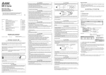
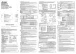
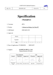
2. To prevent fire, note the following
General-Purpose AC Servo
Install the servo amplifier, servo motor and regenerative resistor on incombustible material. Installing
them directly or close to combustibles will lead to a fire.
Always connect a magnetic contactor (MC) between the main circuit power supply and L1, L2, of the
servo amplifier, and configure the wiring to be able to shut down the power supply on the side of the
servo amplifier’s power supply. If a magnetic contactor (MC) is not connected, continuous flow of a
large current may cause a fire when the servo amplifier malfunctions.
When a regenerative resistor is used, use an alarm signal to switch main power off. Otherwise, a
regenerative transistor fault or the like may overheat the regenerative resistor, causing a fire.
Provide adequate protection to prevent screws and other conductive matter, oil and other combustible
matter from entering the servo amplifier and servo motor.
Always connect a molded-case circuit breaker to the power supply of the servo amplifier.
C Series
MR-C A
MR-C A1
Instructions and Cautions for
Safe Use of AC Servos
If this is the first time for you to use the MELSERVO-C Series, the optionally
available MR-C A Instruction Manual is required. Always purchase them and
use the MELSERVO-C Series safely.
CAUTION
Country/Region
Sales office
Tel/Fax
USA
Mitsubishi Electric Automation Inc.
500 Corporate Woods Parkway, Vernon Hills, IL 60061, USA
Tel :+1-847-478-2100
Fax :+1-847-478-0327
Germany
Mitsubishi Electric Europe B.V. German Branch
Gothaer Strasse 8, D-40880 Ratingen, Germany
Tel :+49-2102-486-0
Fax :+49-2102-486-1120
Mitsubishi Electric Europe B.V. Italian Branch
Viale Colleoni 7
1-20041 Agrate Brianza (Milano), Italy
Tel :+39-39-60531
Fax :+39-39-6053312
China
Mitsubishi Electric Automation (China) Ltd.
4F Zhi Fu Plazz, No. 80 Xin Chang Road
Shanghai 200003, China
Tel :+86-21-6120-0808
Fax :+86-21-6121-2444
Taiwan
Setsuyo Enterprise Co., Ltd.
6F, No.105 Wu-Kung 3rd Rd, Wu-Ku Hsiang, Taipei Hsine, Taiwan
Tel :+886-2-2299-2499
Fax :+886-2-2299-2509
Korea
Mitsubishi Electric Automation Korea Co., Ltd.
3F, 1480-6, Gayang-dong, Gangseo-gu, Seoul
157-200, Korea
Tel :+82-2-3660-9552
Fax :+82-2-3664-8372
Singapore
Mitsubishi Electric Asia Pte, Ltd.
307 Alexandra Road #05-01/02,
Mitsubishi Electric Building Singapore 159943
Tel :+65-6470-2460
Fax :+65-6476-7439
Italy
Do not connect AC power directly to the servo motor. Otherwise, a fault may occur.
The surge absorbing diode installed to the DC relay for control output should be fitted in the specified
direction. Otherwise, the emergency stop and other protective circuits may not operate.
Servo amplifier
Only the voltage specified in the instruction manual should be applied to each terminal, Otherwise,
a burst, damage, etc. may occur.
Connect the terminals correctly to prevent a burst, damage, etc.
Ensure that polarity ( , ) is correct. Otherwise, a burst, damage, etc. may occur.
During power-on or for some time after power-off, do not touch or close a parts (cable etc.) to the
servo amplifier heat sink, regenerative resistor, servo motor, etc. Their temperatures may be high
and you may get burnt or a parts may damaged.
During operation, never touch the rotating parts of the servo motor. Doing so can cause injury.
SG
V+
ALM
PF
ALM
PF
RA
RA
CAUTION
Transport the products correctly according to their mass.
Stacking in excess of the specified number of products is not allowed.
Do not carry the servo motor by the cables, shaft or encoder.
Install the servo amplifier in a load-bearing place in accordance with the instruction manual.
Do not climb or stand on servo equipment. Do not put heavy objects on equipment.
The servo amplifier and servo motor must be installed in the specified direction.
Leave specified clearances between the servo amplifier and control enclosure walls or other
equipment.
Do not install or operate the servo amplifier and servo motor which has been damaged or has any
parts missing.
Do not block intake and exhaust areas of the servo amplifier. Doing so may cause faults.
Do not drop or strike servo amplifier or servo motor. Isolate from all impact loads.
Store or use the servo amplifier and servo motor under the following environmental conditions.
Item
IB(NA)67279-M(1306)MEE
This guide uses recycled paper.
Specifications are subject to change without notice.
Printed in Japan
Ambient
temperature
Ambient
humidity
n Safety Instructions n
Operation
Storage
Operation
Storage
Ambience
(Please read the instructions carefully before using the equipment.)
Install, and peruse all this guide and attached documents before the drive and maintenance and the check.
After that, use these correctly. Use it after it is skilled of the knowledge of the equipment, information on
safety, and all of notes.
In this guide, the safety instruction levels are classified into "WARNING" and "CAUTION".
WARNING
Indicates that incorrect handling may cause hazardous conditions, resulting in
death or severe injury.
CAUTION
Indicates that incorrect handling may cause hazardous conditions, resulting in
medium or slight injury to personnel or may cause
physical damage.
Note that the CAUTION level may lead to a serious consequence according to conditions. Please follow
the instructions of both levels because they are important to personnel safety.
What must not be done and what must be done are indicated by the following diagrammatic symbols.
Altitude
(Note)
Vibration
Environment
Servo amplifier
Servo motor
0 to 55 (non-freezing)
0 to 40 (non-freezing)
32 to 131 (non-freezing)
32 to 104 (non-freezing)
20 to 65 (non-freezing)
15 to 70 (non-freezing)
4 to 149 (non-freezing)
5 to 158 (non-freezing)
80 RH or less
90 RH or less
(non-condensing)
(non-condensing)
90 RH or less (non-condensing)
Indoors (no direct sunlight) Free from corrosive gas, flammable gas,
oil mist, dust and dirt
Max. 1000m (3280 ft) above sea level
[m/s2]
5.9 or less
X Y : 19.6
19.4 or less
X Y : 64
[ft/s2]
[
[
[
[
]
]
]
]
(2) Wiring
: Indicates what must not be done. For example, "No Fire" is indicated by
: Indicates what must be done. For example, grounding is indicated by
.
.
In this guide, instructions at a lower level than the above, instructions for other functions, and so on are
classified into "POINT".
After reading this guide, always keep it accessible to the operator.
1. To prevent electric shock, note the following
WARNING
Before wiring or inspection, turn off the power and wait for 15 minutes or more until the charge lamp
turns off. Otherwise, an electric shock may occur. In addition, always confirm from the front of the
servo amplifier, whether the charge lamp is off or not.
Connect the servo amplifier and servo motor to ground.
Any person who is involved in wiring and inspection should be fully competent to do the work.
Do not attempt to wire the servo amplifier and servo motor until they have been installed. Otherwise,
you may get an electric shock.
Operate the switches with dry hand to prevent an electric shock.
The cables should not be damaged, stressed loaded, or pinched. Otherwise, you may get an electric
shock.
To avoid an electric shock, insulate the connections of the power supply terminals.
CAUTION
Wire the equipment correctly and securely. Otherwise, the servo motor may operate unexpectedly.
Do not install a power capacitor, surge killer or radio noise filter (FR-BIF option) between the servo
motor and servo amplifier.
Connect the wires to the correct phase terminals (U, V, W) of the servo amplifier and servo motor.
Otherwise, the servo motor does not operate properly.
Connect the servo motor power terminal (U, V, W) to the servo motor power input terminal (U, V, W)
directly. Do not let a magnetic contactor, etc. intervene.
Servo amplifier
U
V
W
Servo motor
U
V
W
Servo amplifier
U
M
V
W
U
V
W
Servo motor
M
The year and month of manufacture
Model
Capacity
Applicable power supply
Rated output current
Serial number
KC certification number
CAUTION
CAUTION
Contacts must be opened when the servo-on (SON)
Circuit must be opened
signal, the malfunction (ALM) signal, or the electromagnetic during emergency stop
brake interlock (MBR) signal turns off.
switch.
Servo motor
Hardware special specification
Blank or 2 to 5 digit alphanumeric
(RJ, ED, PX, RU, RZ, etc.)
Power supply
Symbol
Power supply
None 1-phase 200 to 230VAC
1-phase 100 to 120VAC
1
2. COMPLIANCE WITH CE MARKING
2.1 What is CE marking?
(1) EMC directive
The EMC directive applies to the servo units alone. This servo is designed to comply with the
EMC directive. The EMC directive also applies the servo-incorporated machines and equipment.
This requires the EMC filters to be used with the servo-incorporated machines and equipment to
comply with the EMC directive. For specific EMC directive conforming methods, refer to the EMC
Installation Guidelines (IB(NA)67310).
(2) Low voltage directive
The low voltage directive applies also to servo units alone. This servo is designed to comply with
the low voltage directive.
2.2 For compliance
RA
U
Software special specification
Blank, Sn, or Un
(n=00 to 999)
Series name
Adjustment servo motor
Symbol Adjustment servo motor
10
HC-PQ033 053 13
HC-PQ23
20
HC-PQ43
40
The CE marking is mandatory and must be affixed to specific products placed on the European Union.
When a product conforms to the requirements, the CE marking must be affixed to the product. The
CE marking also applies to machines and equipment incorporating servos. When you need a copy of
Declaration of Conformity of CE marking, contact your local sales office.
When it is assumed that a hazardous condition may take place at the occur due to a power failure or a
product fault, use a servo motor with electromagnetic brake or an external brake mechanism for the
purpose of prevention.
Configure a circuit so that the electromagnetic brake activates with the external emergency stop switch
at the same time.
B
Country of origin
(2) Model code
The following describes what each block of a model name indicates. Note that not all the
combinations of the symbols exist.
Provide an external emergency stop circuit to ensure that operation can be stopped and power
switched off immediately.
Any person who is involved in disassembly and repair should be fully competent to do the work.
Before resetting an alarm, make sure that the run signal of the servo amplifier is off to prevent an
accident. A sudden restart is made if an alarm is reset with the run signal on.
Do not modify the equipment.
Use a noise filter, etc. to minimize the influence of electromagnetic interference, which may be caused
by electronic equipment used near the servo amplifier.
Use the servo amplifier with the specified servo motor.
The electromagnetic brake on the servo motor is designed to hold the motor shaft and should not be
used for ordinary braking.
For such reasons as service life and mechanical structure (e.g. where a ball screw and the servo motor
are coupled via a timing belt), the electromagnetic brake may not hold the motor shaft. To ensure
safety, install a stopper on the machine side.
Burning or breaking a servo amplifier may cause a toxic gas. Do not burn or break a servo amplifier.
SON
Securely attach the servo motor to the machine. If attach insecurely, the servo motor may come off
during operation.
The servo motor with reduction gear must be installed in the specified direction to prevent oil leakage.
Take safety measures, e.g. provide covers, to prevent accidental access to the rotating parts of the
servo motor during operation.
Never hit the servo motor or shaft, especially when coupling the servo motor to the machine. The
encoder may become faulty.
Do not subject the servo motor shaft to more than the permissible load. Otherwise, the shaft may
break.
When the equipment has been stored for an extended period of time, contact your local sales
office.
When treating the servo amplifier, be careful about the edged parts such as the corners of the servo
amplifier.
The servo amplifier must be installed in the metal cabinet (control box).
When fumigants that contain halogen materials such as fluorine, chlorine, bromine, and iodine are
used for disinfecting and protecting wooden packaging from insects, they cause malfunction when
entering our products. Please take necessary precautions to ensure that remaining materials from
fumigant do not enter our products, or treat packaging with methods other than fumigation (heat
method). Additionally, disinfect and protect wood from insects before packing products.
(1) Rating plate
CAUTION
Note. Except the servo motor with reduction gear.
1
1.3 Model code definition
Before operation, check the parameter settings. Improper settings may cause some machines to
perform unexpected operation.
The parameter settings must not be changed excessively. Operation will be instable.
(5) Corrective actions
HEAD OFFICE: TOKYO BLDG MARUNOUCHI TOKYO 100-8310
Quantity
1
1
Note. IEC/EN standard-, UL/cUL standard-compliant models.
(3) Test run adjustment
The following instructions should also be fully noted. Incorrect handling may cause a fault, injury, electric
shock, etc.
(1) Transportation and installation
Contents
Servo amplifier
(Note) Protective earth (PE) terminals
MELSERVO-C Series
Instructions and Cautions for Safe Use of AC Servos
(This guide)
SG
V+
(4) Usage
4. Additional instructions
After unpacking, check the rating plate to confirm that the servo amplifier you received are as you
ordered.
Servo amplifier
When the cable is not tightened enough to the terminal block (connector), the cable or terminal block
(connector) may generate heat because of the poor contact. Be sure to tighten the cable with
specified torque.
3. To prevent injury, note the following
M
1.2 Contents of the packing
CAUTION
CAUTION
24VDC
Electromagnetic brake
When any alarm has occurred, eliminate its cause, ensure safety, and deactivate the alarm before
restarting operation.
When power is restored after an instantaneous power failure, keep away from the machine because
the machine may be restarted suddenly (design the machine so that it is secured against hazard if
restarted).
Be sure to perform an appearance inspection of every unit before installation. In addition, have a
final performance inspection on the entire machine/system, and keep the inspection record.
(1) Servo amplifiers and servo motors used
Use the servo amplifiers and servo motors which comply with the IEC/EN standard-compliant
model.
Servo amplifier
:MR-C10A-UE to MR-C40A-UE
Servo motor
:HC-PQ (produced in and after February, 2001)
HC-PQ -UE
(2) Structure
Control box
Reinforced
insulating type
(6) Maintenance, inspection and parts replacement
CAUTION
With age, the electrolytic capacitor of the servo amplifier will deteriorate. To prevent a secondary
accident due to a fault, it is recommended to replace the electrolytic capacitor every 10 years when
used in general environment.
Please contact your local sales office.
(7) General instruction
To illustrate details, the equipment in the diagrams of this guide and instruction manual may have
been drawn without covers and safety guards. When the equipment is operated, the covers and safety
guards must be installed as specified. Operation must be performed in accordance with this guide and
instruction manual.
n DISPOSAL OF WASTE n
Please dispose a servo amplifier, battery (primary battery) and other options according to your local laws
and regulations.
1. INTRODUCTION
1.1 Introduction to the manuals
If this is the first time for you to use the MELSERVO-C Series the optionally available MR-C A
Instruction Manual is required. Please read all carefully to use the MELSERVO-C Series safely.
Reinforced
insulating
transformer Molded-case
circuit breaker
MCCB
Magnetic
contactor
MC
24VDC
power
supply
Servo
amplifier
Servo
motor
M
(4) Power supply
(a) Operate the servo amplifier to meet the requirements of the overvoltage category II set forth in
EN 60664-1. For this purpose, a reinforced insulating transformer conforming to the EN
Standard should be used in the power input section.
(b) For the interface power supply, use a 24VDC power supply with reinforced insulation on I/O
terminals.
(5) Grounding
(a) To prevent an electric shock, the protective earth (PE) terminal (marked ) of the servo
amplifier must be connected to the protective earth (PE) of the control box.
(b) Do not connect two ground cables to the same protective earth (PE) terminal. Always connect
cables to the terminals one-to-one.
(4) Flange
Mount the servo motor on a flange which has the following size or produces an equivalent or
higher heat dissipation effect.
Flange size [mm(in)]
150 150 6
(5.91 5.91 0.24)
250 250 6
(9.84 9.84 0.24)
250 250 12
(9.84 9.84 0.47)
PE terminal
(c) If an earth leakage circuit breaker is used, always earth the protective earth (PE) terminal of
the servo amplifier to prevent an electric shock.
(6) Wiring and Installation
(a) The wires to be connected to the terminal block of the servo amplifier must have crimping
terminals provided with insulating tubes to prevent contact with adjacent terminals.
Crimping terminal
Insulating tube
Wire
(b) Connect the power leads of the HC-PQ series servo motor to the servo amplifier using a
fixed terminal block. Do not connect cables directly.
1000
033 053 13
23
Servo amplifier
Discharge time (min)
MR-C10A(1), 20A(1), 40A
3
Molded-case
circuit breaker
Servo amplifier
MR-C10A
MR-C20A
MR-C10A1
MR-C20A1
MR-C40A
(8) Performing EMC tests
When EMC tests are run on a machine/device into which the servo amplifier has been installed, it
must conform to the electromagnetic compatibility (immunity/emission) standards after it has
satisfied the operating environment/electrical equipment specifications. For the other EMC
directive guidelines on the servo amplifier, refer to the EMC Installation Guidelines
(IB(NA)67310).
- MR-C Series are not intended to be used on a low-voltage public network which supplies
domestic premises;
- radio frequency interference is expected if used on such a network.
The installer shall provide a guide for Installation and use, including recommended mitigation
devices.
3. CONFORMANCE WITH UL/cUL STANDARD
This servo amplifier complies with UL 508C and CSA C22.2 No.14 standard.
Refer to section 1.3 (2) for the servo amplifier model names described in the tables and figures.
(1) Servo amplifier and servo motor used
Use the servo amplifiers and servo motors which comply with UL/cUL standardcompliant model.
Servo amplifier
:MR-C10A-UE to MR-C40A-UE
Servo motor
:HC-PQ (producted in and after february, 2001)
HC-PQ -UE
Use a pair of the servo amplifier and servo motor listed below.
Servo amplifier
MR-C10A (1)
MR-C20A (1)
MR-C40A
(3) Short-circuit current rating (SCCR)
Suitable For Use On A Circuit Capable Of Delivering Not More Than 100 kA rms Symmetrical
Amperes, 500 Volts Maximum.
K5
10
AC250
(Note 1) Wire [mm2]
(Note 3)
P C
U V W
0.75(AWG18)
(Note 2)
0.75(AWG18)
Electromagnetic
brake
0.75(AWG18)
1.25(AWG16)
Table: Recommended Crimping Terminals
Crimping terminal
1.25-2
Applicable tool
YHT-2210
Manufacturer name
Japan Solderless Terminals
(9) Terminal block tightening torque
Terminal block
Main circuit terminal block (TE)
Protective earth (PE) terminal
Terminal screw: M4
Tightening torque [N m] ([lb in])
0.49 to 0.785
(4.34 to 6.95)
1.275
(11.3)
(10)Overload Protection Characteristics
An electronic thermal relay is built in the servo amplifier to protect the servo motor, servo
amplifier and servo motor power line from overloads. The operation characteristics of the
electronic thermal relay are shown below. It is recommended to use an unbalanced
torque-generated machine, such as a vertical motion shaft, so that unbalanced torque is not more
than 70 of the rated torque.
Servo amplifier MR-C series have servo motor overload protection. (The motor full load current is
115 rated current.)
We will repair any failure or defect hereinafter referred to as "failure" in our FA equipment hereinafter referred to as the
"Product" arisen during warranty period at no charge due to causes for which we are responsible through the distributor from
which you purchased the Product or our service provider. However, we will charge the actual cost of dispatching our engineer
for an on-site repair work on request by customer in Japan or overseas countries. We are not responsible for any on-site
readjustment and/or trial run that may be required after a defective unit are repaired or replaced.
1
100
200 250
[Term]
The term of warranty for Product is twelve (12) months after your purchase or delivery of the Product to a place designated by
you or eighteen (18) months from the date of manufacture whichever comes first (“Warranty Period”). Warranty period for
repaired Product cannot exceed beyond the original warranty period before any repair work.
[Limitations]
4. INSPECTION
WARNING
Before starting maintenance and/or inspection, turn off the power and wait
for 15 minutes or more until the charge lamp turns off. Otherwise, an
electric shock may occur. In addition, always confirm from the front of the
servo amplifier whether the charge lamp is off or not.
Any person who is involved in inspection should be fully competent to do
the work. Otherwise, you may get an electric shock. For repair and parts
replacement, contact your safes representative.
CAUTION
Do not perform insulation resistance test on the servo amplifier as
damage may result.
Do not disassemble and/or repair the equipment on customer side.
(1) Inspection
It is recommended to make the following checks periodically.
(a) Check for loose terminal block screws. Retighten any loose screws.
(b) Check the servo motor bearings, brake section, etc. for unusual noise.
(c) Check the cables and the like for scratches and cracks. Perform periodic inspection according to
operating conditions.
(d) Check the servo motor shaft and coupling for misalignment.
(2) Life
The following parts must be changed periodically as listed below. If any part is found faulty, it
must be changed immediately even when it has not yet reached the end of its life, which depends
on the operating method and environmental conditions.
For use in the atmosphere having much oil mist, dust, etc., clean and inspect every three months.
For parts replacement, please contact your sales representative.
Part name
Servo
amplifier
Smoothing capacitor
Servo
motor
Bearings
Encoder
V ring
Standard life
10 years
20,000 to 30,000 hours
20,000 to 30,000 hours
5,000 hours
In operation
10
In servo lock
10
100
200
300
Load ratio [ ]
400420
1000
In operation
10
In servo lock
1
0
100
200
Load ratio [ ]
Name
Indication
Name
Board error
35
12
Memory error 1
20
Encoder error
37
Parameter error
14
Watch dog
30
Regenerative error
50
Over load
52
Error excessive
Memory error 2
31
Over speed
Motor combination
32
Over current
error
33
Over voltage
Command pulse error
EEP-ROM life
The number of write times to the EEP-ROM, which stores parameter settings, etc., is limited to
100,000. If the total number of the following operations exceeds 100,000, the servo amplifier may fail
when the EEP-ROM reaches the end of its useful life.
Writing to the EEP-ROM due to parameter setting changes.
(b) For HC-PQ23
100
Indication
17
16
0
Name
Under voltage
15
1
300320
(3) Even during the term of warranty, the repair cost will be charged on you in the following cases;
(i) : a failure caused by your improper storing or handling, carelessness or negligence, etc., and a failure caused by your
hardware or software problem
(ii) : a failure caused by any alteration, etc. to the Product made on your side without our approval
(iii) : a failure which may be regarded as avoidable, if your equipment in which the Product is incorporated is equipped with
a safety device required by applicable laws and has any function or structure considered to be indispensable
according to a common sense in the industry
(iv) : a failure which may be regarded as avoidable if consumable parts designated in the instruction manual, etc. are duly
maintained and replaced
(v) : any replacement of consumable parts (battery, fan, smoothing capacitor, etc.)
(vi) : a failure caused by external factors such as inevitable accidents, including without limitation fire and abnormal
fluctuation of voltage, and acts of God, including without limitation earthquake, lightning and natural disasters
(vii) : a failure generated by an unforeseeable cause with a scientific technology that was not available at the time of the
shipment of the Product from our company
(viii) : any other failures which we are not responsible for or which you acknowledge we are not responsible for
2. Term of warranty after the stop of production
(1) We may accept the repair at charge for another seven (7) years after the production of the product is discontinued. The
announcement of the stop of production for each model can be seen in our Sales and Service, etc.
(2) Please note that the Product (including its spare parts) cannot be ordered after its stop of production.
3. Service in overseas countries
Our regional FA Center in overseas countries will accept the repair work of the Product. However, the terms and conditions of
the repair work may differ depending on each FA Center. Please ask your local FA center for details.
4. Exclusion of responsibility for compensation against loss of opportunity, secondary loss, etc.
Whether under or after the term of warranty, we assume no responsibility for any damages arisen from causes for which we
are not responsible, any losses of opportunity and/or profit incurred by you due to a failure of the Product, any damages,
secondary damages or compensation for accidents arisen under a specific circumstance that are foreseen or unforeseen by
our company, any damages to products other than the Product, and also compensation for any replacement work,
readjustment, start-up test run of local machines and the Product and any other operations conducted by you.
6. Application and use of the Product
(a) Smoothing capacitor
Affected by ripple currents, etc. and deteriorates in characteristic. The life of the capacitor
greatly depends on ambient temperature and operating conditions. The capacitor will reach
the end of its life in 10 years of continuous operation in normal air-conditioned environment
(surrounding air temperature of 40 (104 ) or less).
(b) Servo motor bearings
When the servo motor is run at rated speed under rated load, change the bearings in 20,000 to
30,000 hours as a guideline. This differs on the operating conditions. The bearings must also
be changed if unusual noise or vibration is found during inspection.
(c) Servo motor V ring
Must be changed in 5,000 hours of operation at rated speed as a guideline. This differs on the
operating conditions. These parts must also be changed if oil leakage, etc. is found during
inspection.
Indication
100
(2) This limited warranty applies only when the condition, method, environment, etc. of use are in compliance with the terms
and conditions and instructions that are set forth in the instruction manual and user manual for the Product and the caution
label affixed to the Product.
Specifications listed in our catalogs, manuals or technical documents may be changed without notice.
5. ALARMS
1000
(1) You are requested to conduct an initial failure diagnosis by yourself, as a general rule. It can also be carried out by us or our
service company upon your request and the actual cost will be charged.
However, it will not be charged if we are responsible for the cause of the failure.
5. Change of Product specifications
(a) For HC-PQ033 to 13
Servo motor
HC-PQ033
HC-PQ053
HC-PQ13
HC-PQ23
HC-PQ43
(2) Installation
The MR-C series have been approved as the products which have been installed in the
electrical enclosure. The minimum enclosure size is based on 150 of each MR-J3 combination.
And also, design the enclosure so that the ambient temperature in the enclosure is 55˚C
(131˚F ) or less. The servo amplifier must be installed in the metal cabinet. For environment,
the units should be used in open type (UL 50) and overvoltage category II or lower. The servo
amplifier needs to be installed at or below of pollution degree 2. For connection, use copper
wires.
Voltage [V]
Note 1. The wires are based on 600V vinyl wires. The wires (U, V, W) in the table assume that the distance
between servo motor and servo amplifier is not more than 30m(98.4feet).
2. Before wiring, twist the wires for connection of the regenerative option (P, C).
3. Crimping terminals and crimping tools are required for the protective earth (PE) on the servo
motor side. Refer to the recommended crimping terminals table for the crimping terminals and
crimping tools.
Operation time[s]
(7) Peripheral devices, options
(a) Use the molded-case circuit breaker and magnetic contactor models which are EN
Standard-compliant products given in the MR-C A Instruction Manual.
(b) The sizes of the wires given in the MR-C A Instruction Manual meet the following
conditions. For use in any other conditions, follow Table 5 and Annex C of EN 60204-1.
Ambient temperature : 40 (104 )
Sheath
: PVC (polyvinyl chloride)
Installation on wall surface or open cable tray
(c) Use the EMC filter for noise reduction.
Fuse
Current [A]
(8) Selection example of wires
To comply with the UL/cUL Standard, use UL-approved copper wires rated at 60/75
(140/167 ) for wiring.
0.75(AWG18)
1. Warranty period and coverage
(11)Over-temperature protection for motor
Motor Over temperature sensing is not provided by the drive.
(7) About wiring protection
For installation in United States, branch circuit protection must be provided, in accordance with
the National Electrical Code and any applicable local codes.
For installation in Canada, branch circuit protection must be provided, in accordance with the
Canada Electrical Code and any applicable provincial codes.
MR-C10A
MR-C20A
MR-C10A1
MR-C20A1
MR-C40A
Warranty
10 In servo lock
Load ratio [ ]
NF30
type 10A
(Note 3)
L1 L2
In
operation
0
Class
NF30
type 5A
Operation time[s]
Terminal block
This product complies with the Radio Wave Law (KC mark). Please note the following to use the
product.
이 기기는 업무용 (A급) 전자파적합기기로서 판 매자 또는 사용자는 이 점을 주의하시기 바라며,
가정외의 지역에서 사용하는 것을 목적으 로 합니다.
(The product is for business use (Class A) and meets the electromagnetic compatibility
requirements. The seller and the user must note the above point, and use the product in a place
except for home.)
100
43
(5) Capacitor discharge time
The capacitor discharge time is as follows.To ensure safety, do not touch the charging section for
15 minutes after power-off.
Servo amplifier
(c) Use the servo motor side power connector which complies with the EN Standard.
The EN Standard-compliant power connector sets are available as options.
(d) The servo amplifier must be installed in the metal cabinet (control box).
South Korea compliance
10000
Servo motor (HC-PQ)
(6) Options, peripheral devices
Use the UL/cUL Standard-compliant products.
Use the following molded-case circuit breaker and fuse.
PE terminal
(c) For HC-PQ43
Operation time[s]
(3) Environment
Operate the servo amplifier at pollution degree 2 or 1 set forth in EN 60664-1. For this purpose,
install the servo amplifier in a control box which is protected against water, oil, carbon, dust, dirt,
etc. (IP54).
(1) For the use of our General-Purpose AC Servo, its applications should be those that may not result in a serious damage
even if any failure or malfunction occurs in General-Purpose AC Servo, and a backup or fail-safe function should operate
on an external system to General-Purpose AC Servo when any failure or malfunction occurs.
(2) Our General-Purpose AC Servo is designed and manufactured as a general purpose product for use at general industries.
Therefore, applications substantially influential on the public interest for such as atomic power plants and other power
plants of electric power companies, and also which require a special quality assurance system, including applications for
railway companies and government or public offices are not recommended, and we assume no responsibility for any
failure caused by these applications when used.
In addition, applications which may be substantially influential to human lives or properties for such as airlines, medical
treatments, railway service, incineration and fuel systems, man-operated material handling equipment, entertainment
machines, safety machines, etc. are not recommended, and we assume no responsibility for any failure caused by these
applications when used.
We will review the acceptability of the abovementioned applications, if you agree not to require a specific quality for a
specific application. Please contact us for consultation.