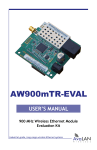
1
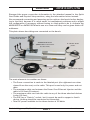
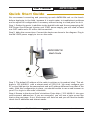
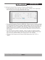
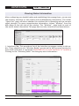
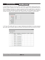
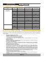
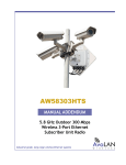
AW58103HTS
AW58103HTM
Manual ADDENDUM
5.8 GHz Outdoor 100 Mbps
Wireless 3-Port Ethernet
Subscriber Unit and Mesh Node Radios
Industrial-grade, long-range wireless Ethernet systems
AvaLAN
W
I
R
E
L
E
S
S
AW58103HTS, HTM
Addendum
Thank you for your purchase of this member of the 5.8 GHz Outdoor 100 Mbps family
of wireless Ethernet radios.
The AW58103HTS is a radio with a dual flat panel high gain directional antenna and a
built in 802.3af Power Over Ethernet 3-port switch. This allows you to place a wireless Ethernet drop at a location and provide power and data connections for up to
three Ethernet devices. 48 VDC power is provided to the three devices via unused
wires in their data cables. Multiple AW58103HTS radios can serve as a Subscriber
Units (clients) in conjunction with an AW58100HTA. Except for the power and data
distribution provided by the switch, the AW58103HTS is functionally identical to the
AW58100HTS. For configuration and testing information, refer to the AW58100HTS
manual attached to this Addendum.
In similar fashion, the AW58103HTM is a radio that is functionally identical to the
AW58100HTM Mesh Node with the addition of the 802.3af POE switch. For configuration and testing information, refer to the AW58100HTS manual attached to this
Addendum.
The AW58103HTS includes:
•
•
•
•
The AW58103HTM includes:
(1) AW58103HTS Subscriber Unit Radio
(1) Heavy Duty Pole-mount Bracket
(1) Power Over Ethernet Injector
(1) 48 VDC 0.5A Power Supply
•
•
•
•
(1) AW58100HTM Mesh Node Radio
(1) Heavy Duty Pole-mount Bracket
(1) Power Over Ethernet Injector
(1) 48 VDC 0.5A Power Supply
If you have any questions when configuring your AvaLAN system, the best place to
get answers is to visit www.avalanwireless.com. You will also find the latest updates
there. If more assistance is needed, send email to [email protected].
To speak to a live technician, please call technical support at the number below
during normal business hours.
© 2012 by AvaLAN Wireless Systems Inc. All rights reserved.
Revision 07.23.2012
125A Castle Drive
Madison, AL 35758
Sales: (866) 533-6216
Technical Support: (650) 384-0000
Customer Service: (650) 641-3011
Fax: (650) 249-3591
Technical Support (650) 384-0000
PAGE 2
www.avalanwireless.com
Addendum
AW58103HTS, HTM
Disregard the power connection information in the attached manual in the Quick
Start Guide and Physical Setup sections, using the information below instead.
We recommend connecting and powering up the units on the bench before deploying in the field, because it is much easier to troubleshoot problems and to adjust
the configuration if necessary without having to climb poles to do it. Activate the
AW58103HTS or AW58103HTM units one at a time until they can be given distinct IP
addresses.
This photo shows how things are connected on the bench:
Power and Data Outputs
to Ethernet Devices
AW58103HTM Shown
(AW58103HTS Connections
are the same)
To 120 VAC 60 Hz
power
Power Input
to Radio
POE
48 VDC Power Supply
The main elements to consider are these:
• The Power connection is made to the labeled port (the rightmost one when
viewed from the rear) on the radio. This port is used only for power and not
data.
• The maximum cable run between the Power Over Ethernet Injector and the
radio is 100 feet (30 meters).
• The maximum cable run from the radio to any of the three attached devices
is also 100 feet.
• The POE has a “Data In” socket, but it cannot be used to support a fourth
device. Nothing should be connected to this socket.
• Total DC power available to the three devices is 25 Watts.
Technical Support (650) 384-0000
PAGE 3
www.avalanwireless.com
AW58103HTS, HTM
Addendum
Notes
Limited Warranty
This product is warranted to the original purchaser for normal use for a period of 360 days from the date
of purchase. If a defect covered under this warranty occurs, AvaLAN will repair or replace the defective
part, at its option, at no cost. This warranty does not cover defects resulting from misuse or modification
of the product.
Technical Support (650) 384-0000
PAGE 4
www.avalanwireless.com
AW58100HTM
User’s Manual
5.8 GHz Outdoor 100 Mbps
Wireless Ethernet Mesh Node
Industrial-grade, long-range wireless Ethernet systems
AvaLAN
W
I
R
E
L
E
S
S
AW58100HTM
User’s Manual
Thank you for your purchase of this member of the 5.8 GHz Outdoor 100 Mbps family
of wireless Ethernet radios.
The AW58100HTM is a mesh node radio. It features dual omnidirectional antennas
and may be used in sets to create a high speed, line-of-sight multipoint-to-multipoint network with 1 Watt EIRP and up to 100 Mbps RF data rate via the latest MIMO
technology.
The AW58100HTM includes:
• (1) AW58100HTM Outdoor 100 Mbps Wireless Ethernet Mesh Node Radio
• (1) Heavy Duty Pole-mount Bracket
• (1) AW-POE Power Over Ethernet Injector
• (1) AW-12VPS 12VDC 0.5A Power Supply
Table of Contents
Quick Start Guide . . . . . . . . . . . . . . . . . . . . . . . . . . . . . . . . . . .
3
Physical Setup . . . . . . . . . . . . . . . . . . . . . . . . . . . . . . . . . . . . .
5
Digital Configuration . . . . . . . . . . . . . . . . . . . . . . . . . . . . . . . . . . . . .
5
Connecting To The Radio . . . . . . . . . . . . . . . . . . . . . . . . . . . . . . . . . . . . .
6
Changing the Configuration - Step By Step . . . . . . . . . . . . . . . . . . .
7
Viewing Status Information . . . . . . . . . . . . . . . . . . . . . . . . . . . . . .
10
Advanced Diagnostic Tools . . . . . . . . . . . . . . . . . . . . . . . . . . . . .
12
Frequency Channels . . . . . . . . . . . . . . . . . . . . . . . . . . . . . . . . . . . . .
16
Warranty and FCC Information . . . . . . . . . . . . . . . . . . . . . . . . . . . .
16
If you have any questions when configuring your AvaLAN system, the best place to
get answers is to visit www.avalanwireless.com. You will also find the latest updates
there. If more assistance is needed, send email to [email protected].
To speak to a live technician, please call technical support at the number below
during normal business hours.
© 2012 by AvaLAN Wireless Systems Inc. All rights reserved.
Revision 07.23.2012
125A Castle Drive
Madison, AL 35758
Sales: (866) 533-6216
Technical Support: (650) 384-0000
Customer Service: (650) 641-3011
Fax: (650) 249-3591
Technical Support (650) 384-0000
PAGE 2
www.avalanwireless.com
User’s Manual
AW58100HTM
Quick Start Guide
We recommend connecting and powering up each AW58100M unit on the bench
before deploying in the field, because it is much easier to troubleshoot problems
and to adjust the configuration if necessary without having to climb poles to do it.
Step 1. Gather the parts: In addition to the AvaLAN radio and the accompanying AWPOE Power Over Ethernet Injector and 12VDC power supply, you will need at least
one CAT5 cable and a PC with a LAN connection.
Step 2. Make the connections: Connect the devices as shown in the diagram. Plug in
the AW-12VPS power supply to turn on the radio.
AW58100HTM
Mesh Node
Step 3. The default IP address of the radio is written on its product label. This address is 192.168.88.11 with a subnet mask of 255.0.0.0. You must configure your
PC’s wired LAN port to the same subnet and an IP address different from that of the
radio. With this configuration in place, you should be able to use a web browser on
your PC to log in to the radio’s interface.
Step 4. Browse to the Access Point’s interface: Enter http://192.168.88.11 into your
web browser’s address bar. If you are successful, you will see a login screen like
that on the next page. If not, the browser will time out and you will need to double
check the IP addresses and subnet masks.
Technical Support (650) 384-0000
PAGE 3
www.avalanwireless.com
AW58100HTM
User’s Manual
click
Step 5. Log In to the radio: The default login name is “admin” and the password is
“password.” If your login is successful, you should see the “Quick Set” page similar
to this:
(You may need to scroll around in the page to see all the elements, particularly if
you have a lower resolution monitor or are using Firefox as your browser.)
Step 6. To determine if your wireless mesh network is functioning correctly, you will
need to give each AW58100HTM Mesh Node a unique IP address. There is a box near
the upper right corner of the “Quick Set” page that displays the current value and
allows you to change it. A special notation is used for this entry: Use /x at the end
of the IP Address to specify the subnet mask: /8 for 255.0.0.0, /16 for 255.255.0.0,
/24 for 255.255.255.0 and /32 for 255.255.255.255. Enter a new IP Address and
subnet making sure you will be able to browse to the new address with your computer. Also, make sure that the new IP address is unique on your LAN subnet. Click
the “Apply Configuration” button to make the change. Nothing appears to happen,
but you have been disconnected and will need to browse to the new IP Address to
login again.
Step 7. Repeat the above steps for each Mesh Node in your network, giving them
each a unique IP address. You may wish at the same time to perform the other
Digital Configuration steps beginning on Page 5. Each radio must have a unique IP
address with the other configuration parameters set alike.
Utilizing state of the art MIMO technology, the AW58100HTM achieves very high data
rate through a combination of dual spacial streams and higher level OFDM modulation.
Technical Support (650) 384-0000
PAGE 4
www.avalanwireless.com
User’s Manual
AW58100HTM
The default RF configuration provides a 20 MHz channel bandwidth with 5 selectable
non-overlapping channels to choose from. When configured and mounted, the radios operate as a fully-connected peer-to-peer wireless network with automatic path
routing and self-healing.
Physical Setup
1. The factory default digital configuration may be used, except that each radio
must be given a unique IP address as described in the Quick Start Guide. You may
want to perform the procedures in the next section before mounting the radios in
their final locations. Particularly if data security is important, you will likely want
to change passwords and encryption keys. If RF interference sources are present,
you may want to change the channel frequency or bandwidth.
2. Mount each unit securely using the mounting brackets provided or other means
as necessary.
3. The units have two omnidirectional antennas to provide dual RF streams for higher data rates. Each Mesh Node radio needs to be located with no more than a 1/2
mile line-of-sight path to whichever other Mesh Nodes it is intended to link with.
4. Power is provided to the units by means of their Ethernet cables, allowing the
power supplies to be located at convenient locations. The included power-over-Ethernet injectors (POE) provide the means for adding DC power to unused wires in the
cable (pins 4,5 negative and 7,8 positive). The POE male RJ-45 connector may be
plugged into your network router or, at a remote site, your remote data source such
as a camera. The female RJ-45 sockets on the POE should be connected via your LAN
cable to the AvaLAN radio. Then the AW-12VPS power supply is connected to the P5
socket on the POE and plugged into a 120 VAC source. Each radio is provided with a
cable clamping device that allows an RJ45 plug on the cable to pass through and can
be tightened down around the cable to provide a weatherproof seal.
Digital Configuration
These five configuration elements must be set for each radio:
1.IP address/subnet mask
2.User password
3.SSID (Service Set Identifier)
4.Encryption pass phrase
5.Frequency Channel
For a set of Mesh Nodes in a network, the IP addresses must be different and all other
configuration parameters must be the same. The following pages will give you step by
step instructions for changing these configuration elements.
Technical Support (650) 384-0000
PAGE 5
www.avalanwireless.com
AW58100HTM
User’s Manual
Connecting to the radio
1. Digital configuration is done by means of the radio’s built in browser interface.
The unit should be powered on and connected at least temporarily to a network
containing a computer that can run a conventional web browser.
2. Using your web browser, connect to the radio as described in the Quick Start
Guide found earlier in this manual.
3. The initial screen after a successful login is “Quick Set”:
4. Each screen provides a menu on the left to navigate from
section to section. The menu looks like this when sections are
expanded:
In addition, many screens “drill down” when an area within the
screen is clicked.
In the upper right of the screen is a label that tells you the version of the web interface. If the version number is not the same
as shown below, you might want to visit www.avalanwireless.com
to see if a newer version of this manual exists before proceeding
further.
You are cautioned not to use the “back” button on your browser to attempt to
move back to earlier screens. If you do, you will be logged out and will need to
login again.
Technical Support (650) 384-0000
PAGE 6
www.avalanwireless.com
User’s Manual
AW58100HTM
Changing The Configuration - Step by Step
Please remember that if you change the IP Address or User Password and forget
their new values, you have locked yourself out of the browser interface. Recovery
can be a time-consuming process and will require the help of AvaLAN Technical
Support. If you are changing parameters over the RF link (we do not recommend
this), be sure to make the remote changes first because the link will be broken if
the SSIDs or Security Pass Phrases do not agree.
1. Setting the IP Address and subnet mask:
• On the Main Menu at the left side of the browser window, click “IP
Addressing”, then click “Set IP/subnet.”
• The current IP Address is shown. Click it to bring up the page that allows you
to change it.
• A special notation is used for this entry: Use /x at the end of the IP Address
to specify the subnet mask: /8 for 255.0.0.0, /16 for 255.255.0.0, /24 for
255.255.255.0 and /32 for 255.255.255.255. Enter a new IP Address and subnet making sure you will be able to browse to the new address with your computer. Also, make sure that the new IP address is unique on your LAN subnet.
• Click “Apply.” Nothing appears to happen, but you have been disconnected
and will need to browse to the new IP Address to login again. Note that the IP
Address is also visible and may be changed on the “Quick Set” screen.
2. Setting the User Password:
• On the Main Menu at the left side of the browser window, click “System”,
then click “Password.”
• Enter the old password and the new password twice in the boxes indicated.
• Click the “Change” button.
• Log out and log back in to test.
Technical Support (650) 384-0000
PAGE 7
www.avalanwireless.com
AW58100HTM
User’s Manual
3. Setting the SSID:
• On the Main Menu at the left side of the browser window, click “Wireless.”
Then click anywhere in the “Wireless_Radio” row to bring up the “Interface
<Wireless_Radio>” page.
• The second line down in the content table shows the current SSID and provides a text box to change it. Change the SSID to a new value of your choice
and click “OK” or “Apply.”
• You will need to browse to the radio’s IP Address and login again after the
change.
4. Setting the Encryption Pass Phrase:
• On the same page as above for setting the SSID, a box is provided for entering
the Encryption Key.
Technical Support (650) 384-0000
PAGE 8
www.avalanwireless.com
User’s Manual
AW58100HTM
5. Setting the Access Point Frequency Channel and Bandwidth:
• On the Main Menu at the left side of the browser window, click “Quick Set.”
This returns you to the page presented after login.
• The default Frequency Channel is 5805 MHz. There are more choices available
in the dropdown list than are legal or appropriate for this set of products. Do
not change the “Band” dropdown box setting. Please choose from among the
frequencies shown in the table on the last page of this manual. Make sure
that you choose channels for mesh networks operating in proximity that do
not overlap.
• The default Channel Width is 20 MHz, which provides the highest possible
data rate. More range can be achieved at the expense of data rate by choosing a narrower Channel Width. Your choices are 5, 10 or 20 MHz.
• Change to the Frequency and Channel Width desired and click “OK” or
“Apply.”
Technical Support (650) 384-0000
PAGE 9
www.avalanwireless.com
AW58100HTM
User’s Manual
Viewing Status Information
After configuring your AvaLAN radios and establishing links among them, you can use
the browser interface to view status and troubleshooting Information. The initial
“Quick Set” page will show whether the wireless link is operating and the current
signal strength. For more comprehensive information, choose “Wireless” from the
Main Menu at the left side of the window. The “Wireless” page leads to most of
the useful status information.This page has two tabs, Interfaces and Associations.
1. Interfaces Tab: This provides a list of the interface processes running in this radio. There should be one “Wireless_Radio” process and a WDS process running for
each mesh node that is connected. (CAUTION! Do not click the little “D” buttons.)
Clicking on the “Wireless_Radio” line brings up more information:
Technical Support (650) 384-0000
PAGE 10
www.avalanwireless.com
User’s Manual
AW58100HTM
This page displays the current RF frequency, the SSID, current transmission rates,
amount of data sent and received since last reboot, drops and errors. Also shown
are graphs of megabits per second and packets per second during the last five minutes or so. The graphs are well labeled and auto-scale to fit the data. After viewing
the status, you may leave the page by clicking “Cancel” or by using the Main Menu.
(If you click “OK” or “Apply”, the process will restart and briefly interrupt the data
flow.
Back on the “Wireless” page, you can click on a WDS process line to see similar
information about traffic with just that particular radio.
2. Associations Tab: This provides a list of radios that are connected, showing their
MAC addresses, how long the connection has been up, seconds since last activity,
Transmit and receive signal strength in dBm and the transmit and receive data rate
in use.
Clicking on the white text line brings up detailed status of the remote radio:
This screen is a very tall window with several interesting sections shown on the
next page. The top “General” section shows information that may be useful if you
contact AvaLAN Technical Support.
The “Signal” section shows transmit and receive signal strength overall and by individual MIMO channel.
The “Statistics” section shows the link transmit and receive rates.
Technical Support (650) 384-0000
PAGE 11
www.avalanwireless.com
AW58100HTM
User’s Manual
Advanced Diagnostic Tools
You may want to contact AvaLAN Technical Support for more guidance before using
the additional tools described in this section.
The radio’s browser interface unlocks some additional features if you login as
an advanced user instead of the standard user described earlier in this manual.
From the browser initial login page, if you enter a user name of “adv_user” with
a password of “passw0rd” (a zero replacing the “o”), you will see and be able to
do anything the standard user (user name “admin”) can do, plus some additional
tasks. Obviously, you can change the password for “adv_user” and may want to do
so for security purposes.
Technical Support (650) 384-0000
PAGE 12
www.avalanwireless.com
User’s Manual
AW58100HTM
When you log in as the advanced user, the navigation menu
looks like this. There are three new tabs:
• Files - Lists the files associated with the web interface of
the radio. This information may be useful when contacting
AvaLAN Technical Support. You are cautioned not to delete or alter these files without instructions from AvaLAN
Technical Support. (It is very easy to render your radio inoperative by doing so.)
• Tools - Four different diagnostic tools are provided here to
facilitate troubleshooting and performance optimization.
• WinBox - Downloads a simple finder utility that can be used on Windowscompatible PCs to locate AW58100 family products on your LAN.
Tools:
1. Bandwidth Test: This is a tool that will generate a high volume of traffic for a
particular radio link and produce a graph of the data rate achieved. The test can
only be performed from one radio to another over the wireless link, so enter the IP
address of the remote radio you wish to exchange data with. You can also specify
the protocol, tcp or udp, and the packet size and data direction.
Technical Support (650) 384-0000
PAGE 13
www.avalanwireless.com
AW58100HTM
User’s Manual
2. Flood Ping: This tool can be used to generate a continuous string of ping commands to any IP address the radio can see on its subnet. Ping uses ICMP (Internet
Control Message Protocol) to request a packet from the target device, waits for a
return and then immediately sends another request. You can specify the IP address
to ping, the packet count, packet size in bytes and the timeout in milliseconds.
3. IP Scan: The radio will scan a range of addresses (by default, its entire subnet)
and report back the MAC address and other information about each device it finds.
Technical Support (650) 384-0000
PAGE 14
www.avalanwireless.com
User’s Manual
AW58100HTM
4. Ping: This tool is like the normal Internet ping command and is less disruptive of
network traffic than Flood Ping. A request is sent and the time needed for a reply
is measured. After an interval, the process is repeated. By default, continuous ping
requests are send until you click “Stop.” Or you can specify a count, much like the
ping command used in the Windows or Unix command line.
6. WinBox: Clicking this tab will cause your browser to download a utility for installation on your PC (Windows win32 compatibility only). It may be possible to run it
on Linux or MAC OSX by using a Windows emulator such as Wine. By clicking the
discovery button labeled “...”, any AvaLAN AW58100 family products on your LAN
will be reported. (You may also see other devices as well if they respond to the CDP
protocol used by the utility.) The popup window will show the IP address of each
radio and will facilitate logging in if you have lost or forgotten these addresses.
This utility has some powerful features that can totally disrupt the functioning of
your product. You are not encouraged to experiment or you may need to rely upon
AvaLAN Technical Support to restore proper functionality.
Technical Support (650) 384-0000
PAGE 15
www.avalanwireless.com
AW58100HTM
User’s Manual
Frequency Channels
Frequency
Band
802.11a
Upper Band
(FCC specifies
for Outdoor use)
ISM Band
Frequency
MHz
5730
5735
5740
5745
5750
5755
5760
5765
5770
5775
5780
5785
5790
5795
5800
5805
5810
5815
5820
5825
5830
5835
5845
Non-overlapping
20 MHz Bandwidth
Non-overlapping
10 MHz Bandwidth
OK
OK
OK
OK
OK
OK
OK
OK
OK
OK
OK - Default
OK
OK
OK
OK
OK
Non-overlapping
5 MHz Bandwidth
OK
OK
OK
OK
OK
OK
OK
OK
OK
OK
OK
OK
OK
OK
OK
OK
OK
OK
OK
OK
OK
OK
OK
Limited Warranty
This product is warranted to the original purchaser for normal use for a period of 360 days from the date
of purchase. If a defect covered under this warranty occurs, AvaLAN will repair or replace the defective
part, at its option, at no cost. This warranty does not cover defects resulting from misuse or modification
of the product.
Technical Support (650) 384-0000
PAGE 16
www.avalanwireless.com