1
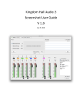
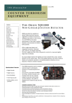
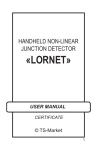
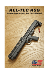
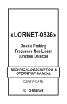
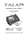
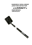
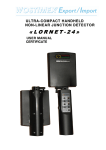
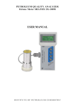
NR-2000 User Manual CONTENTS 1 Application 2 2 Description 4 3 Technical data 5 4 Principle of operation 6 5 Design 7 5.1 Accessories 11 5.2 Packing 13 5.3 NR-2000 usage condition and restrictions 14 5.4 Getting started 15 5.5 NR-2000 workability test 16 5.6 NR-2000 operation 17 Operation termination and packing 19 6.1 Battery charging 20 13 Shipping and storage 22 14 Certificate of acceptance 22 15 Warranty 23 6 This Manual is intended for explanation “NR-2000” Non-linear Junction Detector design & principle of operation as well as directions for its use. For proper equipment use study this Manual in depth. 1 NR-2000 User Manual NR-2000 application NR-2000 Non-linear Junction Detector is intended for searching concealed electronics like eavesdropping installations, Remote Controlled Improvised Explosive Devices (RC IED) and etc. as well as other items that contain semi-conductor elements. NOTE: NR-2000 can detect typical targets in every operational mode: active, stand-by or even switched-off. NR-2000 typical targets: Radio-mikes Microphone amplifiers Wired mikes Video & audio recorders SIM cards Fig. 1 NR-2000 Non-linear Junction Detector Electronic timing devices Devices with infrared (IR) or ultrasonic data & control channel Remote controlled improvised explosive devices 2 NR-2000 User Manual NR-2000 possible application fields - Crime scene investigation for hard evidence of explosive terrorism that contains any electronic components and its remains: triggers, communication facilities and etc.). - Searching for Improvised Explosive Device (IED) that contains electronic components in typical urban environment. NOTE 1: In practice NR-2000 is immune to interfering signals typical to urban conditions. NOTE 2: The IED detection range is comparable with that of an ‘Eagle’ NLJD – Russian standard tool for field operations: 7-10 meters. NOTE 3: Fortunate combination of significant detection range with low radiation level and practical immunity to unban interference guarantee NR2000 operator from spontaneous IED triggering. - Various premise investigation for mobile phones and SIM-cards hidden in domestic articles. NOTE: NR-2000 ensures mobile phones and SIM-cards detection in moist environment and light construction materials up to the distance of 1m and 0.5m respectively. - Searching for eavesdropping devices concealed in light building structures, furniture and various home appliances as well as their reliable localization. NOTE 1: NR-2000 can easily detect targets in building structures behind their reinforcement elements (steel grid and etc.) NOTE2: NR-2000 provides its operator with an opportunity to discriminate between industrial electronic elements and metal-to-metal contacts, so called ‘corrosion diodes’. Thus, NR-2000 NLJD represents a comprehensive multi-purpose tool with mid-power output and outstanding searching ability and rate. 3 NR-2000 User Manual Description NR-2000 is supplied as detecting set (see Table 1 below). 3 8 10 6 9 2 7 4 1 5 Fig. 2 NR-900EM complete set Table 1 1 2 3 4 5 6 7 8 9 10 Main Unit (transceiver) with Antenna module and Control unit Soshine 18650 rechargeable cell Headphones ‘Mini Maglite’ torch Forearm support Shoulder belt (not shown) Charger Imitator (test unit) Carry bag Soshine AC power adapter Soshine car adapter User Manual (not shown) 4 1 4 1 1 1 1 1 1 1 1 1 NR-2000 User Manual Technical data Table 2 Scale ‘2’ readings under following conditions: - standard test unit detection range - 1±0.05m - min output & min received signal attenuation Probing signal maximal pulse power Probing signal output attenuation Receiver input signal attenuation Indication Operational condition: - operational temperature range - temperature limits - relative humidity (under +25C) Power supply Continuous operation time - searching mode - 20K Weight: - Main unit (transceiver) with battery - Complete set in carry bag 5 At least 30dB Not less 17 W 8 steps 1.5dB each 4 steps 10dB Audio & LED display +5C…+40C 20C…+50C Not more 85±3% 2xLi-Ion Rechargeable cells Not less 4h Not less 1.5h 2.2kg 5.5kg NR-2000 User Manual Principle of operation NR-2000 detector represents a portable device that consists of antenna system, probing signal transmitter and 2 receivers tuned to the double & triple frequencies of the emitted signal. Mono-harmonic probing signal emitted by transmitter is converted by nonlinear elements (industrial semi-conductor or corrosion metal-oxide-metal structure) to poly-harmonic one and re-radiated into an ambient space. The probing signal level is adjusted by the detector Control unit. 2F 3F F Fig.3 NR-2000 principal of operation Re-radiated the 2-nd & the 3-rd harmonic of the probing signal are received and processed by above-mentioned receivers. Control unit is used to switch over them. The received signals levels are displayed by two bar-graph scales: ‘2’ (red) & ‘3’ (green) respectively. Furthermore, at the same time tonal acoustic signal is reproduced by the headphones. The tonal signal level corresponds to that of the received electric signals. Volume control is adjusted by ‘SND’ button of the Control unit. At that a corresponding bar-graph scale is switched over for sound level indication for one sec. The received signal level can be adjusted by Control unit with appropriate LED confirmation. 20K-mode activated by Control unit is used for revealed target identification. This auxiliary mode allows operator to detect probable probing signal amplitude modulation. 6 NR-2000 User Manual Design NR-2000 Main unit consist of antenna module, probing signal transmitter unit, two receivers, telescopic bar and control unit with LED display (fig.2). 3 4 7 2 1 8 5 9 6 Fig.4 NR-2000 Main unit design 10 1. 2. 3. 4. 5. 6. 7. 8. 9. 10. Antenna module Antenna module joint Telescopic bar with level-locks Control unit with display Grip Battery compartment Handle Torch Forearm support Headphones Telescopic bar length can be adjusted by means of 2 level-locks . UHF cables pass through the telescopic bar. They are permanently fixed to the antenna module and transceiver unit. The unique ‘Bullpup’ design provides NR-2000 ergonomic advantages in any possible application. 7 NR-2000 User Manual 1 NR-2000 antenna module is fasten to the tip of 3-elbou telescopic bar (fig. 3). Its elevation can be fixed in a wanted position by a joint with a holder screw (item 1). Fig.5 Antenna elevation adjustment Forearm support is attached to main unit body with a spring lock (fig. 4, item L). L In addition forearm support is used also as electric torch bracket. Fig.6 Forearm support with a torch For better operator convenient NR-2000 main unit is equipped with shoulder belt and forearm support: - the belt over an operator shoulder; - support over an operator forearm. USEFUL HINT: NR-2000 main unit in operating position is supported by the grip in a manner similar to ‘bull-pup’ design rifle handling. 8 NR-2000 User Manual Headphone connection jack is on the back side of the main unit housing (fig. 5). Fig.7 NR-2000 headphone connection Battery compartment (two Li-Ion rechargeable cells) with a chamber hatch are located in the bottom part of the NR-2000 grip (fig. 7) Fig. 8 NR-2000 battery compartment 9 NR-2000 User Manual NR-2000 control unit (fig. 7) in essence consists of LED display for representing acting operational mode and received signals level as well as control board with 9 non-fastening buttons that are used for adjusting and altering operational modes. Control unit is placed on antenna system bar and are permanently coupled to the Main unit ((see also fig. 2). 1. Power ON/OFF button 2. Probing signal ON/OFF 3. 20K mode activation switch 4. 2-nd & 3-rd harmonic switch over button with 1 confirmation LED 5. Headphone volume control 2 6. Probing signal output level scale 10 3 7. Output level adjustment button 4 8. Received signal attenuation 9. Attenuator scale 10. Received signal LED bar- 5 graph indicator (2-nd & 3-rd 9 harmonics) 6 8 Fig. 9 NR-2000 control unit with LED display 10 NR-2000 User Manual Accessories NR-900EMS power supple is provided by the battery of two Li-Ion rechargeable cells. Cell rated voltage is 3.7V with 2800mAh element capacity. Fig. 10 Soshine 18650 For battery charging Soshine SC-S1 max charger (supplied) is used 1– Soshine SC-S1 max charger unit 2 – Soshine DС 12V car adapter 3 – Soshine AC power adapter 1 2 3 Fig. 11 Soshine SC-S1 charger package 11 NR-2000 User Manual Soshine AC adapter allows to charge the battery from the mains 100 – 240 V, 50/60 Hz. In case of another AC adapter in a supplied set – check its parameters referring the label on AC adapter body. Soshine DС 12V car adapter is intended for battery charging from the motocar 12V DC net. Imitator (test unit) is intended for NR-2000 workability control (fig.10). Fig. 12 NR-2000 Imitator (test unit) It represents HF semi-conductor diode (2D521A - in accordance with Russian classification) in a solid plastic body 14 x 165 mm. Mini-Maglite torch is intended for detection area lighting (if necessary). The torch is powered by two AA cells. The forearm support is equipped with a special clamp to fasten the torch. Fig. 13 Mini-Maglite torch 12 NR-2000 User Manual Packing Complete set of NR-2000 equipment is packed into a dedicated shockproof carry bag (fig.12). The bag is made of a durable synthetic fabric, has rigid frame and soft inserts. Handy grips and a shoulder strap make its transportation easy and comfortable. Fig. 14 NR-2000 in a carry bag 13 NR-2000 User Manual NR-2000 operation NR-2000 usage condition and restrictions After long-term exposure to a low temperature keep the detector packed in a standard packing at least 2 hours for evening up its temperature with the environment. Operating NR-2000 keeps corresponding safety measures Safety precautions for the open RF emitters: - Do not direct NR-2000 antenna to the human from the distance less than one meter. - Avoid prolonged presence of personnel in a main lobe of NR-2000 antenna diagram. NOTE: Probing signal power density at the distance of 1 meter along the maximum of NR-2000 antenna directional radiation pattern does not exceed Russian State Standard 12.1.006-84 (Russian State Sanitary Norm) for UHF-equipment serviceman under continuous 8-hours operation. 14 NR-2000 User Manual Getting started Unpack NR-2000 detecting set. Connect headphones to the corresponding jack on the main unit body. Install two AA-cells into the battery compartment. Pay attention their polarity referring the engraving on the main unit side panel near the battery compartment. Close the battery compartment hatch. Fig. 15 How to install batteries Press button to switch on NR-2000 detector. At that the following mode is activated: - Transmitter is OFF; - Receivers are ON to control noise surrounding. - Headphones are coupled to the 2-nd harmonic receiver output. - Input signals attenuation is in -10 dB state; - Volume control is in the mid-position. Use ATT button to adjust maximum receiver sensitivity. Direct Antenna module to various directions switching over 2-nd & 3-rd receivers outputs to evaluate the interference environments. In case of a certain noise chose the antenna direction with no noise in the headphones. 15 NR-2000 User Manual NR-2000 workability test Press 20K button to switch off 20K mode Press TX button to activate probing signal transmitter Use PWR button to adjust the minimum probing signal output Point out NR-2000 antenna module to standard imitator (test unit) from the 0.4m distance (fig. 14) Fig. 16 NR-2000 workability test 250Hz tonal audio signal will be head in the headphones confirmed by 2-nd harmonic bar-graph LED indication. Move imitator in various directions noting LED bar-graph indication of control unit obtaining full scale indication for the 2-nd harmonic. Then use ATT+ button to engage successive step of input attenuator. Make sure that every stroke corresponds to an adequate attenuator activation and 2-nd harmonic indication declination. Press PWR+ button to boost probing signal output level. Make sure that every stroke corresponds to an adequate PWR scale increment and 2-nd harmonic indication gain. Switch off the detector USERFUL HINT: In case of battery discharge 2-nd & 3-rd LED bar-graph scales are lit by turns NR-2000 detector is suitable for operation 16 NR-2000 User Manual NR-2000 Operation WARNING: NR-2000 detector is a high-sensitive radio electronic device. Before operation, please, make sure to remove all semiconductorcontaining items from your clothing and munitions. Switch on and check its operability according to NR-2000 workability test section. Carry out target search under maximum (if possible) probing signal output and highest receiver sensitivity. That will ensure the maximum detection range. Acting transmitter output and receiver sensitivity level are defined by existing interference environment right on spot of a searching operation. ] Fig.17 Antenna system scanning diagram In general, the noise surroundings are formed by UHF external signals and non-linear targets that could not be eliminated or removed from the area. Scan antenna module along the examined surface. Once the tone signal of ~250 Hz becomes audible in the headphones, localize the response signal based on the maximum audio level in headphones. To do this alter antenna module position and orientation, variate the probing signal emitted power with PWR (▲,▼) buttons, and change the receiver sensitivity with ATT (▲,▼) buttons. Use SND button to switch over receiver outputs to compare second and third harmonic levels and to identify the source of the response signal. If the second harmonic signal level is considerably higher than that of the third one, it is highly probable that there are certain industrial semiconductor components within the detection area. If the third harmonic signal level substantially exceeds the second harmonic level, a corrosive nonlinear scatterer is the most likely to be the source of the response signal. 17 NR-2000 User Manual 20K mode is used to identify a detected object. Natural corrosive nonlinear scatterer (two metal items divided by oxide layer) has an unstable junction. Under mechanical impact (tap) in close vicinity of detected nonlinear junction Operator will hear a wheeze and cracks in the headphones that corresponds to above mentioned impact. 1 A man-made target (device, gear and etc.) has more stable junctions and produce a weak respond to mechanical impact. Active devices, for instance, clockwork produce a regular signal without any external impact. NOTE: its highly recommended switch over Detector to 20K mode when receiver signal level achieves 20 dB because of this mode lower detection capacity. USEFUL HINT: 1. For better Operator convenience one can adjust telescopic bar length. To do so, release the level-lock (see fig 2, item 3). 2. To alter antenna module elevation loose holder screw (see fig. 3 & 17, item 1). Fig.18 NR-2000 antenna module elevation Tighten mounting elements after detector hardware readjustment 18 NR-2000 User Manual Operation termination and packing When operation is over – press button to switch off NR-2000 detector. Remove rechargeable cells from battery compartment, fold the telescopic bar, disconnect headphones and put Detector into carry bag referring fig. 16-18. Put charger package, power supply elements, torch, imitator and forearm support into the carrier bag's pocket. Close the pocket (see fig.15). Put Main unit, headphones and shoulder belt into the middle compartment of the carry bag (see fig.16). Put the instruction manual into the pocket on the carry bag cover. Close the bag cover and zip up the bag. Fasten handy grips with Velcro fastener (see fig. 17). Fig.19-21 NR-2000 packing order 19 NR-2000 User Manual Battery charging Soshine SC-S1 max charger is intended for rechargeable cells charging. 1 – LED charging channel indication 2 – Adapter connection socket 3 – Soshine 18650 2800mAh Li-Ion rechargeable cells 3 Fig. 22 Soshine SC-S1 max charger with four cells inserted for charging. 1 2 Charging order Insert 2 or 4 cells into Soshine charger chamber (if necessary slide ‘minus’ spring contact) Pay special attention to cell polarity referring indication on the charger chamber. Couple AC power adapter or DC 12V car adapter to the socket. Connect AC power adapter to the mains (100-240V, 50/60 Hz) or car adapter to a corresponding cigarette lighter socket. After switching on the power the charger will check every charging channel operability and initiate the charging mode. Charging time for Soshine 18650 2800mAh Li-Ion rechargeable cells with Soshine SC-S1 max charger :4h for 2 cells and 8h - for 4 cells. After battery charging completion unplug AC adapter from the mains and then from the charger. NOTE: The battery (cells) can be unplugged from the charger during any charging stage without any failure to the battery or the charger itself. 20 NR-2000 User Manual Charging mode LED indication (see table 3) Table 3 Charging process status LED light mode 4 x LEDs light up ‘red’ then switch over to ‘green’ Charger workability self -test Defective or cells of a wrong type are installed ( Ni-Mh, Ni-Cd and etc.) Alter ‘green’ to ‘red’ back and forth Charging mode start Red 80%-90% charge is obtained Blinking green Fully charged Green Cell’s wrong polarity Dead Charger operation precautionary measures Do not try to charge primary cells! That can initiate an explosion and provoke the fire. Refer inscription on the cell body. Do not block vent holes on the bottom of the charger housing. Don’t place it on a soft, surface (carpet, blanket, seat covering and etc.). Charger is intended for indoor use only. Protect it from moisture and perspiration water. Do not switch on the charger and/or power adapters with the obvious presence of moisture inside the device. Do not try to disassemble or modify the device. Do not use it as a surrogate power source for a certain gadget. The device terminals are intended for charging appropriate cells only. Charger is an electronic device with high frequency circuits and violent operating current. The wrong operation could cause an electrical shock. Do not leave the charger and/or AC power adapter coupled to the mains unattended for a long time. In spite of several protection circuits used in the charger scheme there is a certain probability of abnormal mode that will cause the fire 21 NR-2000 User Manual Shipping and storage NR-900EM can be shipped in a standard packing in a passenger cabin by any kind of transport. Prevent the device in standard packing from shock and vibration. Store packed device under the temperature from +5 up to +40C and relative humidity no more than 80 % under +25C Certificate of Acceptance Non-linear Junction Detector NR-2000 works No _____________ is in conformity with main technical parameters and is accepted for use. Seller _______________ Date ________________ 22 NR-2000 User Manual Warranty Warranty period for NR-2000 is 12 months from the date of sale. Manufacturer guarantees normal functioning of the device on the assumption of the following all requirements of this Manual by the User and in case of malfunction within the Warranty period Manufacturer will repair the device free of charge. Customer complaints are not accepted and warranty maintenance do not cover the following cases: 1. Mechanical damage of the device’s units or parts. 2. Traces of independent unauthorized repair and/or warranty sealing damage. 3. The device’s Works number mismatches to that mentioned in a Certificate of Acceptance NOTE 1: Warranty period does not cover the battery. NOTE 2: Post-warranty service is accomplished under separate order 23 NR-2000 User Manual FOR NOTES _________________________________ _________________________________ _________________________________ _________________________________ _________________________________ _________________________________ _________________________________ _________________________________ _________________________________ _________________________________ _________________________________ _________________________________ _________________________________ 24